WO2017142059A1 - Cartridge for water purifier, and water purifier - Google Patents
Cartridge for water purifier, and water purifier Download PDFInfo
- Publication number
- WO2017142059A1 WO2017142059A1 PCT/JP2017/005860 JP2017005860W WO2017142059A1 WO 2017142059 A1 WO2017142059 A1 WO 2017142059A1 JP 2017005860 W JP2017005860 W JP 2017005860W WO 2017142059 A1 WO2017142059 A1 WO 2017142059A1
- Authority
- WO
- WIPO (PCT)
- Prior art keywords
- water purifier
- filter medium
- outer cylinder
- inner cylinder
- adhesive
- Prior art date
Links
- XLYOFNOQVPJJNP-UHFFFAOYSA-N water Substances O XLYOFNOQVPJJNP-UHFFFAOYSA-N 0.000 title claims abstract description 168
- 230000000903 blocking effect Effects 0.000 claims abstract description 55
- 239000012510 hollow fiber Substances 0.000 claims description 66
- 239000012528 membrane Substances 0.000 claims description 66
- 239000000853 adhesive Substances 0.000 claims description 60
- 230000001070 adhesive effect Effects 0.000 claims description 60
- 239000004745 nonwoven fabric Substances 0.000 claims description 32
- 238000011049 filling Methods 0.000 claims description 27
- 230000002093 peripheral effect Effects 0.000 claims description 23
- 239000004831 Hot glue Substances 0.000 claims description 21
- 229920002635 polyurethane Polymers 0.000 claims description 13
- 239000004814 polyurethane Substances 0.000 claims description 13
- 239000013464 silicone adhesive Substances 0.000 claims description 11
- 239000006260 foam Substances 0.000 claims description 9
- 239000000463 material Substances 0.000 abstract description 28
- OKTJSMMVPCPJKN-UHFFFAOYSA-N Carbon Chemical compound [C] OKTJSMMVPCPJKN-UHFFFAOYSA-N 0.000 description 39
- 238000001914 filtration Methods 0.000 description 19
- 238000000034 method Methods 0.000 description 18
- 238000011144 upstream manufacturing Methods 0.000 description 16
- -1 polypropylene Polymers 0.000 description 15
- 238000004519 manufacturing process Methods 0.000 description 13
- 238000005266 casting Methods 0.000 description 11
- 239000008213 purified water Substances 0.000 description 11
- 239000008399 tap water Substances 0.000 description 10
- 235000020679 tap water Nutrition 0.000 description 10
- POIUWJQBRNEFGX-XAMSXPGMSA-N cathelicidin Chemical compound C([C@@H](C(=O)N[C@@H](CCCNC(N)=N)C(=O)N[C@@H](CCCCN)C(=O)N[C@@H](CO)C(=O)N[C@@H](CCCCN)C(=O)N[C@@H](CCC(O)=O)C(=O)N[C@@H](CCCCN)C(=O)N[C@@H]([C@@H](C)CC)C(=O)NCC(=O)N[C@@H](CCCCN)C(=O)N[C@@H](CCC(O)=O)C(=O)N[C@@H](CC=1C=CC=CC=1)C(=O)N[C@@H](CCCCN)C(=O)N[C@@H](CCCNC(N)=N)C(=O)N[C@@H]([C@@H](C)CC)C(=O)N[C@@H](C(C)C)C(=O)N[C@@H](CCC(N)=O)C(=O)N[C@@H](CCCNC(N)=N)C(=O)N[C@@H]([C@@H](C)CC)C(=O)N[C@@H](CCCCN)C(=O)N[C@@H](CC(O)=O)C(=O)N[C@@H](CC=1C=CC=CC=1)C(=O)N[C@@H](CC(C)C)C(=O)N[C@@H](CCCNC(N)=N)C(=O)N[C@@H](CC(N)=O)C(=O)N[C@@H](CC(C)C)C(=O)N[C@@H](C(C)C)C(=O)N1[C@@H](CCC1)C(=O)N[C@@H](CCCNC(N)=N)C(=O)N[C@@H]([C@@H](C)O)C(=O)N[C@@H](CCC(O)=O)C(=O)N[C@@H](CO)C(O)=O)NC(=O)[C@H](CC=1C=CC=CC=1)NC(=O)[C@H](CC(O)=O)NC(=O)CNC(=O)[C@H](CC(C)C)NC(=O)[C@@H](N)CC(C)C)C1=CC=CC=C1 POIUWJQBRNEFGX-XAMSXPGMSA-N 0.000 description 9
- 241000894006 Bacteria Species 0.000 description 8
- HEDRZPFGACZZDS-UHFFFAOYSA-N Chloroform Chemical compound ClC(Cl)Cl HEDRZPFGACZZDS-UHFFFAOYSA-N 0.000 description 8
- 239000004743 Polypropylene Substances 0.000 description 8
- 229920001155 polypropylene Polymers 0.000 description 8
- 229920005989 resin Polymers 0.000 description 7
- 239000011347 resin Substances 0.000 description 7
- 239000004698 Polyethylene Substances 0.000 description 6
- 150000001336 alkenes Chemical class 0.000 description 6
- 239000004744 fabric Substances 0.000 description 6
- JRZJOMJEPLMPRA-UHFFFAOYSA-N olefin Natural products CCCCCCCC=C JRZJOMJEPLMPRA-UHFFFAOYSA-N 0.000 description 6
- 229920000573 polyethylene Polymers 0.000 description 6
- 229920000098 polyolefin Polymers 0.000 description 6
- 229920000122 acrylonitrile butadiene styrene Polymers 0.000 description 5
- 238000005520 cutting process Methods 0.000 description 5
- 230000001681 protective effect Effects 0.000 description 5
- 239000000126 substance Substances 0.000 description 5
- XEEYBQQBJWHFJM-UHFFFAOYSA-N Iron Chemical compound [Fe] XEEYBQQBJWHFJM-UHFFFAOYSA-N 0.000 description 4
- 239000011230 binding agent Substances 0.000 description 4
- 239000003795 chemical substances by application Substances 0.000 description 4
- 238000003466 welding Methods 0.000 description 4
- 239000004793 Polystyrene Substances 0.000 description 3
- NIXOWILDQLNWCW-UHFFFAOYSA-N acrylic acid group Chemical group C(C=C)(=O)O NIXOWILDQLNWCW-UHFFFAOYSA-N 0.000 description 3
- 230000000694 effects Effects 0.000 description 3
- 150000002500 ions Chemical class 0.000 description 3
- 239000007788 liquid Substances 0.000 description 3
- 238000000465 moulding Methods 0.000 description 3
- 229920002492 poly(sulfone) Polymers 0.000 description 3
- 229920002223 polystyrene Polymers 0.000 description 3
- 238000004382 potting Methods 0.000 description 3
- GNKTZDSRQHMHLZ-UHFFFAOYSA-N [Si].[Si].[Si].[Ti].[Ti].[Ti].[Ti].[Ti] Chemical compound [Si].[Si].[Si].[Ti].[Ti].[Ti].[Ti].[Ti] GNKTZDSRQHMHLZ-UHFFFAOYSA-N 0.000 description 2
- XECAHXYUAAWDEL-UHFFFAOYSA-N acrylonitrile butadiene styrene Chemical compound C=CC=C.C=CC#N.C=CC1=CC=CC=C1 XECAHXYUAAWDEL-UHFFFAOYSA-N 0.000 description 2
- 239000004676 acrylonitrile butadiene styrene Substances 0.000 description 2
- 229920006127 amorphous resin Polymers 0.000 description 2
- 239000011324 bead Substances 0.000 description 2
- 238000005452 bending Methods 0.000 description 2
- 238000000071 blow moulding Methods 0.000 description 2
- 238000010586 diagram Methods 0.000 description 2
- 238000009826 distribution Methods 0.000 description 2
- 239000005038 ethylene vinyl acetate Substances 0.000 description 2
- 239000000835 fiber Substances 0.000 description 2
- 238000010438 heat treatment Methods 0.000 description 2
- 229910052742 iron Inorganic materials 0.000 description 2
- 229920001200 poly(ethylene-vinyl acetate) Polymers 0.000 description 2
- 239000011148 porous material Substances 0.000 description 2
- 239000000843 powder Substances 0.000 description 2
- 238000003825 pressing Methods 0.000 description 2
- 238000004804 winding Methods 0.000 description 2
- 230000037303 wrinkles Effects 0.000 description 2
- ZAMOUSCENKQFHK-UHFFFAOYSA-N Chlorine atom Chemical compound [Cl] ZAMOUSCENKQFHK-UHFFFAOYSA-N 0.000 description 1
- JOYRKODLDBILNP-UHFFFAOYSA-N Ethyl urethane Chemical compound CCOC(N)=O JOYRKODLDBILNP-UHFFFAOYSA-N 0.000 description 1
- 229920000877 Melamine resin Polymers 0.000 description 1
- 229930182556 Polyacetal Natural products 0.000 description 1
- 239000004695 Polyether sulfone Substances 0.000 description 1
- XUIMIQQOPSSXEZ-UHFFFAOYSA-N Silicon Chemical compound [Si] XUIMIQQOPSSXEZ-UHFFFAOYSA-N 0.000 description 1
- GWEVSGVZZGPLCZ-UHFFFAOYSA-N Titan oxide Chemical compound O=[Ti]=O GWEVSGVZZGPLCZ-UHFFFAOYSA-N 0.000 description 1
- 229910000323 aluminium silicate Inorganic materials 0.000 description 1
- 230000004071 biological effect Effects 0.000 description 1
- 230000015572 biosynthetic process Effects 0.000 description 1
- 238000005119 centrifugation Methods 0.000 description 1
- 229910052801 chlorine Inorganic materials 0.000 description 1
- 239000000460 chlorine Substances 0.000 description 1
- 239000011248 coating agent Substances 0.000 description 1
- 238000000576 coating method Methods 0.000 description 1
- 230000000052 comparative effect Effects 0.000 description 1
- 230000006835 compression Effects 0.000 description 1
- 238000007906 compression Methods 0.000 description 1
- 230000000994 depressogenic effect Effects 0.000 description 1
- HNPSIPDUKPIQMN-UHFFFAOYSA-N dioxosilane;oxo(oxoalumanyloxy)alumane Chemical compound O=[Si]=O.O=[Al]O[Al]=O HNPSIPDUKPIQMN-UHFFFAOYSA-N 0.000 description 1
- 238000007599 discharging Methods 0.000 description 1
- 238000005516 engineering process Methods 0.000 description 1
- 239000003822 epoxy resin Substances 0.000 description 1
- 239000010419 fine particle Substances 0.000 description 1
- 239000012530 fluid Substances 0.000 description 1
- 230000002209 hydrophobic effect Effects 0.000 description 1
- JDSHMPZPIAZGSV-UHFFFAOYSA-N melamine Chemical compound NC1=NC(N)=NC(N)=N1 JDSHMPZPIAZGSV-UHFFFAOYSA-N 0.000 description 1
- 238000002156 mixing Methods 0.000 description 1
- 238000012986 modification Methods 0.000 description 1
- 230000004048 modification Effects 0.000 description 1
- 239000002245 particle Substances 0.000 description 1
- 229920002239 polyacrylonitrile Polymers 0.000 description 1
- 239000004417 polycarbonate Substances 0.000 description 1
- 229920000515 polycarbonate Polymers 0.000 description 1
- 229920000647 polyepoxide Polymers 0.000 description 1
- 229920006393 polyether sulfone Polymers 0.000 description 1
- 229920000139 polyethylene terephthalate Polymers 0.000 description 1
- 239000005020 polyethylene terephthalate Substances 0.000 description 1
- 229920006324 polyoxymethylene Polymers 0.000 description 1
- 229920012287 polyphenylene sulfone Polymers 0.000 description 1
- 238000000746 purification Methods 0.000 description 1
- 230000005855 radiation Effects 0.000 description 1
- 229910052710 silicon Inorganic materials 0.000 description 1
- 239000010703 silicon Substances 0.000 description 1
- 229920005992 thermoplastic resin Polymers 0.000 description 1
- OGIDPMRJRNCKJF-UHFFFAOYSA-N titanium oxide Inorganic materials [Ti]=O OGIDPMRJRNCKJF-UHFFFAOYSA-N 0.000 description 1
Images


Classifications
-
- B—PERFORMING OPERATIONS; TRANSPORTING
- B01—PHYSICAL OR CHEMICAL PROCESSES OR APPARATUS IN GENERAL
- B01D—SEPARATION
- B01D63/00—Apparatus in general for separation processes using semi-permeable membranes
- B01D63/02—Hollow fibre modules
- B01D63/024—Hollow fibre modules with a single potted end
- B01D63/0241—Hollow fibre modules with a single potted end being U-shaped
-
- B—PERFORMING OPERATIONS; TRANSPORTING
- B01—PHYSICAL OR CHEMICAL PROCESSES OR APPARATUS IN GENERAL
- B01D—SEPARATION
- B01D63/00—Apparatus in general for separation processes using semi-permeable membranes
- B01D63/02—Hollow fibre modules
- B01D63/024—Hollow fibre modules with a single potted end
-
- B—PERFORMING OPERATIONS; TRANSPORTING
- B01—PHYSICAL OR CHEMICAL PROCESSES OR APPARATUS IN GENERAL
- B01D—SEPARATION
- B01D63/00—Apparatus in general for separation processes using semi-permeable membranes
- B01D63/02—Hollow fibre modules
- B01D63/031—Two or more types of hollow fibres within one bundle or within one potting or tube-sheet
-
- C—CHEMISTRY; METALLURGY
- C02—TREATMENT OF WATER, WASTE WATER, SEWAGE, OR SLUDGE
- C02F—TREATMENT OF WATER, WASTE WATER, SEWAGE, OR SLUDGE
- C02F1/00—Treatment of water, waste water, or sewage
- C02F1/001—Processes for the treatment of water whereby the filtration technique is of importance
- C02F1/003—Processes for the treatment of water whereby the filtration technique is of importance using household-type filters for producing potable water, e.g. pitchers, bottles, faucet mounted devices
-
- C—CHEMISTRY; METALLURGY
- C02—TREATMENT OF WATER, WASTE WATER, SEWAGE, OR SLUDGE
- C02F—TREATMENT OF WATER, WASTE WATER, SEWAGE, OR SLUDGE
- C02F1/00—Treatment of water, waste water, or sewage
- C02F1/28—Treatment of water, waste water, or sewage by sorption
-
- C—CHEMISTRY; METALLURGY
- C02—TREATMENT OF WATER, WASTE WATER, SEWAGE, OR SLUDGE
- C02F—TREATMENT OF WATER, WASTE WATER, SEWAGE, OR SLUDGE
- C02F1/00—Treatment of water, waste water, or sewage
- C02F1/28—Treatment of water, waste water, or sewage by sorption
- C02F1/283—Treatment of water, waste water, or sewage by sorption using coal, charred products, or inorganic mixtures containing them
-
- C—CHEMISTRY; METALLURGY
- C02—TREATMENT OF WATER, WASTE WATER, SEWAGE, OR SLUDGE
- C02F—TREATMENT OF WATER, WASTE WATER, SEWAGE, OR SLUDGE
- C02F1/00—Treatment of water, waste water, or sewage
- C02F1/44—Treatment of water, waste water, or sewage by dialysis, osmosis or reverse osmosis
-
- C—CHEMISTRY; METALLURGY
- C02—TREATMENT OF WATER, WASTE WATER, SEWAGE, OR SLUDGE
- C02F—TREATMENT OF WATER, WASTE WATER, SEWAGE, OR SLUDGE
- C02F1/00—Treatment of water, waste water, or sewage
- C02F1/44—Treatment of water, waste water, or sewage by dialysis, osmosis or reverse osmosis
- C02F1/444—Treatment of water, waste water, or sewage by dialysis, osmosis or reverse osmosis by ultrafiltration or microfiltration
-
- E—FIXED CONSTRUCTIONS
- E03—WATER SUPPLY; SEWERAGE
- E03C—DOMESTIC PLUMBING INSTALLATIONS FOR FRESH WATER OR WASTE WATER; SINKS
- E03C1/00—Domestic plumbing installations for fresh water or waste water; Sinks
- E03C1/02—Plumbing installations for fresh water
- E03C1/10—Devices for preventing contamination of drinking-water pipes, e.g. means for aerating self-closing flushing valves
-
- B—PERFORMING OPERATIONS; TRANSPORTING
- B01—PHYSICAL OR CHEMICAL PROCESSES OR APPARATUS IN GENERAL
- B01D—SEPARATION
- B01D2311/00—Details relating to membrane separation process operations and control
- B01D2311/26—Further operations combined with membrane separation processes
- B01D2311/2626—Absorption or adsorption
-
- B—PERFORMING OPERATIONS; TRANSPORTING
- B01—PHYSICAL OR CHEMICAL PROCESSES OR APPARATUS IN GENERAL
- B01D—SEPARATION
- B01D2313/00—Details relating to membrane modules or apparatus
- B01D2313/20—Specific housing
-
- B—PERFORMING OPERATIONS; TRANSPORTING
- B01—PHYSICAL OR CHEMICAL PROCESSES OR APPARATUS IN GENERAL
- B01D—SEPARATION
- B01D2313/00—Details relating to membrane modules or apparatus
- B01D2313/44—Cartridge types
-
- B—PERFORMING OPERATIONS; TRANSPORTING
- B01—PHYSICAL OR CHEMICAL PROCESSES OR APPARATUS IN GENERAL
- B01D—SEPARATION
- B01D35/00—Filtering devices having features not specifically covered by groups B01D24/00 - B01D33/00, or for applications not specifically covered by groups B01D24/00 - B01D33/00; Auxiliary devices for filtration; Filter housing constructions
- B01D35/02—Filters adapted for location in special places, e.g. pipe-lines, pumps, stop-cocks
- B01D35/04—Plug, tap, or cock filters filtering elements mounted in or on a faucet
-
- B—PERFORMING OPERATIONS; TRANSPORTING
- B01—PHYSICAL OR CHEMICAL PROCESSES OR APPARATUS IN GENERAL
- B01J—CHEMICAL OR PHYSICAL PROCESSES, e.g. CATALYSIS OR COLLOID CHEMISTRY; THEIR RELEVANT APPARATUS
- B01J20/00—Solid sorbent compositions or filter aid compositions; Sorbents for chromatography; Processes for preparing, regenerating or reactivating thereof
- B01J20/28—Solid sorbent compositions or filter aid compositions; Sorbents for chromatography; Processes for preparing, regenerating or reactivating thereof characterised by their form or physical properties
- B01J20/28014—Solid sorbent compositions or filter aid compositions; Sorbents for chromatography; Processes for preparing, regenerating or reactivating thereof characterised by their form or physical properties characterised by their form
- B01J20/28028—Particles immobilised within fibres or filaments
-
- C—CHEMISTRY; METALLURGY
- C02—TREATMENT OF WATER, WASTE WATER, SEWAGE, OR SLUDGE
- C02F—TREATMENT OF WATER, WASTE WATER, SEWAGE, OR SLUDGE
- C02F2201/00—Apparatus for treatment of water, waste water or sewage
- C02F2201/002—Construction details of the apparatus
- C02F2201/006—Cartridges
-
- C—CHEMISTRY; METALLURGY
- C02—TREATMENT OF WATER, WASTE WATER, SEWAGE, OR SLUDGE
- C02F—TREATMENT OF WATER, WASTE WATER, SEWAGE, OR SLUDGE
- C02F2307/00—Location of water treatment or water treatment device
- C02F2307/06—Mounted on or being part of a faucet, shower handle or showerhead
-
- E—FIXED CONSTRUCTIONS
- E03—WATER SUPPLY; SEWERAGE
- E03C—DOMESTIC PLUMBING INSTALLATIONS FOR FRESH WATER OR WASTE WATER; SINKS
- E03C1/00—Domestic plumbing installations for fresh water or waste water; Sinks
- E03C1/02—Plumbing installations for fresh water
- E03C1/04—Water-basin installations specially adapted to wash-basins or baths
- E03C1/0404—Constructional or functional features of the spout
Definitions
- the present invention relates to a water purifier cartridge for purifying tap water and a water purifier incorporating the water purifier cartridge.
- water purifiers that purify tap water include faucet direct-coupled water purifiers that are directly connected to the outlets of taps and under-sink types that are installed under sinks.
- the number of water purifiers with built-in faucets that incorporate water purifier cartridges (hereinafter also referred to as cartridges) is increasing. Since there is no need to attach a separate body to the outlet of the faucet, it is preferable in appearance, and there is an advantage that it is not necessary to go under the sink when replacing the cartridge, so that it can be easily replaced.
- the shower head which is a discharge port, can switch between purified water and raw water, and some can switch between DC water and shower water.
- a cartridge of a water purifier with a built-in faucet there is a cartridge in which a hollow fiber membrane module is disposed on the downstream side of an activated carbon molded body as disclosed in Patent Document 1, for example.
- the activated carbon molded body used in this cartridge it is necessary to add a binder in addition to the activated carbon when molding the activated carbon, and there is a problem that the amount of activated carbon is reduced in order to mold to a predetermined volume. . That is, the filtration capacity corresponding to the volume of the activated carbon molded body cannot be exhibited. If the cartridge is made larger, the life can be extended. However, there has been a problem that the faucet containing the cartridge becomes larger, making it difficult to use in the kitchen.
- activated carbon in which an annular space (activated carbon filling portion) between an outer cylinder and an inner cylinder made of a single nonwoven fabric is filled with granular activated carbon and closed with a closing member.
- a cartridge provided with a section. Since the activated carbon part used for this cartridge does not contain a binder, it can exhibit a filtration capacity corresponding to the volume of the activated carbon filling part.
- the activated carbon filling portion is filled with granular activated carbon and closed with a closing member, and the end of the outer cylinder is bent inward at the edge of the closing member by an iron or the like, and closed. It is pressed and fixed to the upper surface of the member.
- a problem is found that wrinkles are inevitably generated at the end of the outer cylinder pressed against and fixed to the upper surface of the closing member, and granular activated carbon leaks from the wrinkles.
- the outer cylinder is significantly longer than the inner cylinder, there is also a problem that the granular activated carbon filled in the portions having different lengths between the outer cylinder and the inner cylinder cannot be effectively used.
- the present invention can increase the filling amount per unit space of the granular filter medium, can exhibit a filtering ability corresponding to the volume of the granular filter medium, and prevents the granular filter medium from leaking.
- An object of the present invention is to provide a water purifier cartridge that is small and has a long life, and a water purifier.
- the water purifier cartridge of the present invention comprises a granular filter medium, an inner cylinder that supports the granular filter medium from the inside, passes the water without passing through the granular filter medium, supports the granular filter medium from the outside, and passes the granular filter medium through it.
- An outer cylinder through which water passes a cap member that connects one end of the inner cylinder and one end of the outer cylinder and communicates with the inner diameter side flow path, an inner cylinder blocking member that closes the other end of the inner cylinder, A cylinder closing member and an end adhesive that bonds and fixes the outer cylinder, and the inner cylinder closing member, the outer cylinder, and the end adhesive are integrated to close the opening of the other end of the outer cylinder. It is characterized by that.
- the inner cylinder closing member is in contact with the inner peripheral surface of the outer cylinder and has a filling port for the particulate filter medium.
- a filter medium blocking auxiliary member that blocks the filling port, and the inner cylinder blocking member, the filter medium blocking auxiliary member, the outer cylinder, and the end adhesive are integrated so as to block the opening surface at the other end of the outer cylinder. It is preferable that
- the filter medium blockage assisting member is a foam.
- the end adhesive is a hot melt adhesive.
- the end adhesive is a polyurethane adhesive.
- the end adhesive is preferably a silicone adhesive.
- a hollow fiber membrane bundle bundled in a U-shape, and a hollow fiber membrane case that houses the hollow fiber membrane bundle and fixes the hollow fiber membrane at one end, and the other end of the hollow fiber membrane case and a cap member Are preferably connected in a liquid-tight manner.
- the inner cylinder is a non-woven fabric.
- the outer cylinder is preferably a nonwoven fabric, and the thickness of the nonwoven fabric constituting the outer cylinder is preferably 0.5 to 1 mm.
- the water purifier cartridge is preferably a faucet built-in water purifier cartridge.
- the cartridge for a water purifier with a built-in faucet is disposed in a state where it can be attached to and detached from the water purifier with a built-in faucet.
- the water purifier cartridge is disposed in a state where it can be attached to and detached from the water purifier.
- the granular filter medium, the inner cylinder that supports the granular filter medium from the inside passes the water without passing the granular filter medium
- the outer cylinder that supports the granular filter medium from the outside and passes the water without passing the granular filter medium A cap member that connects one end of the inner cylinder and one end of the outer cylinder and has an opening communicating with the inner cylinder, an inner cylinder blocking member that closes the other end of the inner cylinder, and an inner cylinder blocking member and the outer cylinder
- the inner cylinder closing member, the outer cylinder, and the end adhesive are integrated so as to close the opening surface of the other end of the outer cylinder.
- the inner cylinder blocking member, the outer cylinder, and the end adhesive are integrated so as to block the granular filter medium, thereby preventing the granular filter medium from leaking from the water purifier cartridge.
- the end adhesive used for the water purifier cartridge of the present invention has fluidity when manufactured (particularly, when the end adhesive is applied to the opening of the other end of the outer cylinder), and thereafter Since it is hardened and loses fluidity, the end adhesive material having fluidity can firmly fill the gap formed between the inner cylinder closing member and the outer cylinder, and the inner cylinder closing member, the outer cylinder, and This is because the end adhesive is integrated and closes the opening surface of the other end of the outer cylinder, so that leakage of the particulate filter medium from the annular space can be prevented after the end adhesive is cured.
- the filter medium filling portion is filled with the powder filter medium, it is not necessary to add a binder for forming the filter medium, so that a filtration capacity corresponding to the volume of the filter medium can be exhibited.
- the granular filter medium can be filled with the central axes of the outer cylinder and the inner cylinder aligned. Since the radial width of the cartridge for water purifier in the annular space formed by the outer cylinder and the inner cylinder becomes uniform and the flow of water becomes uniform, the filtering ability of the granular filter medium can be sufficiently exhibited.
- It has a filter medium blocking auxiliary member that blocks the filling port, and the inner cylinder blocking member, the filter medium blocking auxiliary member, the outer cylinder, and the end adhesive are integrated so as to block the opening surface at the other end of the outer cylinder. Then, it can prevent more reliably that the granular filter medium with which the annular space was filled leaks out of the annular space.
- the filter medium blockage auxiliary member is a foam
- the irregularities at the top of the granular filter medium can be absorbed, and a space for pouring the end adhesive can be secured. It can be in close contact with the outer cylinder without gaps, can prevent the end adhesive from flowing into the granular filter medium, and at the same time contributes to preventing leakage of the granular filter medium.
- the end adhesive is a hot melt adhesive, polyurethane adhesive, or silicone adhesive, it has better fluidity at the time of manufacture (when applying liquid to the opening at the other end of the outer cylinder) It can be spread without leaving, and the leakage of the particulate filter medium can be surely prevented. Since it loses fluidity after curing and has sufficient strength, leakage of the particulate filter medium can be reliably prevented both when the water purifier cartridge is mounted and when it is used.
- Some hot-melt adhesives, polyurethane adhesives, and silicone adhesives are suitable as water contact members for water purifiers that do not elute harmful substances even when in contact with water, ensuring the safety of purified water.
- a hollow fiber membrane bundle bundled in a U-shape, and a hollow fiber membrane case that houses the hollow fiber membrane bundle and fixes the hollow fiber membrane at one end, and the other end of the hollow fiber membrane case and the cap member are liquid-tight Even if the bacteria enter the activated carbon and grow for some reason, the bacteria can be captured by the hollow fiber membrane during passage of water, and the bacteria do not enter the purified water.
- the thickness of the inner cylinder and the outer cylinder can be reduced, and the filling amount of the granular filter medium can be sufficiently increased.
- the thickness of the non-woven fabric of the outer cylinder is 0.5 to 1 mm, the filling amount of the granular filter medium can be maximized, and the shape can be firmly maintained against the water flow resistance.
- the above-mentioned water purifier cartridge is a faucet built-in water purifier cartridge or a water faucet built-in water purifier that can be attached and detached, the effect of being small and having a long life can be further exhibited.
- FIG. 1 is a longitudinal sectional conceptual view showing an example of a water purifier cartridge in the present invention.
- FIG. 2 is a partial enlarged view on the upstream side of a longitudinal sectional conceptual diagram showing an example of a water purifier cartridge in the present invention.
- FIG. 3 is a partially cutaway conceptual cross-sectional view showing an example of a state in which the water purifier cartridge according to the present invention is built in a faucet.
- FIG. 4 is a perspective conceptual view of an embodiment of an intermediate cap (cap member) included in the water purifier cartridge according to the present invention as viewed from the upstream side.
- FIG. 5 is a perspective conceptual view of an embodiment of an intermediate cap (cap member) provided in the water purifier cartridge according to the present invention as viewed from the downstream side.
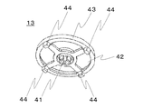
- FIG. 6 is a perspective conceptual view of one embodiment of the correction cap (inner cylinder blocking member) provided in the water purifier cartridge according to the present invention as viewed from the upstream side.
- FIG. 7 is a perspective conceptual view of one embodiment of the correction cap (inner cylinder blocking member) provided in the water purifier cartridge according to the present invention as viewed from the downstream side.
- FIG. 8 is a perspective conceptual view of an embodiment of the filter medium closing ring (filter medium blocking auxiliary member) provided in the water purifier cartridge according to the present invention as viewed from the upstream side.
- FIG. 1 is a schematic longitudinal sectional view showing an example of a water purifier cartridge according to the present invention
- FIG. 2 is a partially enlarged view of the upstream side of the water purifier cartridge shown in FIG.
- FIG. 3 is a partially cutaway cross-sectional view showing an example of a state in which the water purifier cartridge according to the present invention is attached to the water purifier.
- the water purifier cartridge 1 includes an end adhesive 11, a filter medium blocking ring (filter medium blocking auxiliary member) 12, a correction cap (inner cylinder blocking member) 13, an outer cylinder 14, and an inner cylinder from the upstream side. 15, an intermediate cap (cap member) 16, a hollow fiber membrane module 17, a connection cap 18, and an outlet cap 19 are arranged in this order, and these members are connected to other members.
- An annular space 20 surrounded by the filter medium closing ring 12, the outer cylinder 14, the inner cylinder 15, and the intermediate cap 16 is densely filled with the granular filter medium 21.
- the outer cylinder 14 has a cylindrical shape, and the opening is adjusted so that the particulate filter medium 21 does not pass and water passes. Those having an opening of 20 to 50 ⁇ m can be preferably used.
- a non-woven fabric obtained by cutting a non-woven fabric of polyolefin-based heat-bonding fiber into a cylindrical shape by winding the non-woven fabric a plurality of times around a heated shaft and cutting it into a predetermined length may be inexpensive. However, it is not limited to this.
- An olefin-based material such as polypropylene may be melted and formed into a cylindrical shape by blow molding.
- a non-woven fabric or mesh cloth may be welded or bonded to a cylindrical resin molded body having an opening on the outer peripheral surface.
- the outer cylinder 14 is a nonwoven fabric. Since the outer cylinder is a non-woven fabric, the outer cylinder is thinner than the case where the outer cylinder has a mesh member fixed to the inner peripheral surface of the outer case having a side opening, and the size of the cartridge for the water purifier is smaller. Can be filled with more granular filter media.
- the thickness of the outer cylinder 14 formed of non-woven fabric is preferably 0.5 to 1 mm.
- the thickness is less than 0.5 mm, there is a problem that the granular filter medium 21 is swelled by being filled or depressed due to water flow resistance during water flow. If the thickness exceeds 1 mm, the outer diameter of the cartridge is limited, and the cartridge protrudes to the inner diameter side. If the thickness is 0.5 to 1 mm, it will not swell or sink, and the filling amount of the particulate filter medium 21 will not be inappropriately reduced.
- the downstream end (one end) of the outer cylinder 14 is firmly bonded to the intermediate cap (cap member) 16 with a hot-melt adhesive.
- a hot-melt adhesive it is not limited to this.
- a polyurethane adhesive or a silicone adhesive may be used instead of the hot melt adhesive.
- the upstream end portion (the other end) of the outer cylinder 14 is integrally sealed with an end adhesive 11 that is a hot-melt adhesive. That is, on the other end side of the outer cylinder 14, the correction cap (inner cylinder blocking member) 13, the filter medium blocking ring (filter medium blocking auxiliary member) 12, the outer cylinder 14, and the end adhesive 11 are disposed integrally. In addition, the particulate filter medium 21 is closed by arranging the end adhesive 11 so as to cover the entire opening surface of the other end of the outer cylinder 14. In the embodiment of the present invention shown in FIG.
- the present invention is not limited to the above embodiment. Therefore, as another embodiment, the entire opening surface of the other end of the outer cylinder is not covered with the end adhesive, and the inner cylinder blocking member disposed in the opening of the outer cylinder and the other end of the outer cylinder.
- an end adhesive is disposed so as to close a boundary (gap) formed by the three members of the filter medium blockage assisting member, and the granular filter medium is blocked to prevent leakage.
- the force for fixing each member is further improved, and the manufacturing process can be further simplified, as shown in FIG. It is preferable that the entire opening surface of the other end is covered with the end adhesive 11.
- the hot melt adhesive has high fluidity at the time of manufacture (at the time of coating liquid to the opening at the other end of the outer cylinder), and has a high effect of filling the gap. Since the hardness becomes sufficiently high after curing, leakage of the particulate filter medium can be surely prevented both when the water purifier cartridge is mounted and when it is used.
- the bonding of the upstream end portion of the outer cylinder 14 is not limited to the hot melt adhesive. A polyurethane adhesive or a silicone adhesive may be used.
- the inner cylinder 15 is also cylindrical like the outer cylinder 14, and the opening is adjusted so that the particulate filter medium 21 does not pass and water passes.
- Those having an opening of 20 to 50 ⁇ m can be preferably used.
- a non-woven fabric obtained by cutting a non-woven fabric of polyolefin-based heat-bonding fiber into a cylindrical shape by winding the non-woven fabric a plurality of times around a heated shaft and cutting it into a predetermined length may be inexpensive. However, it is not limited to this.
- An olefin-based material such as polypropylene may be melted and formed into a cylindrical shape by blow molding.
- a non-woven fabric or mesh cloth may be welded or bonded to a cylindrical resin molded body having an opening on the outer peripheral surface.
- the inner cylinder 15 is preferably a nonwoven fabric. Since the inner cylinder is a non-woven fabric, the inner cylinder is thinner than the case where the inner cylinder has a mesh member fixed to the inner peripheral surface of the inner case having a side opening, and the size of the cartridge for the water purifier is smaller. Can be filled with more granular filter media.
- the thickness of the inner cylinder 15 formed of non-woven fabric is preferably 0.5 to 2 mm. If the thickness is less than 0.5 mm, there will be a problem of sinking due to water flow resistance and pressure loss of the granular filter medium during water flow. If the thickness exceeds 2 mm, it will protrude to the inner diameter side, and the amount of the particulate filter medium 21 filled will be reduced. If the thickness is 0.5 to 2 mm, there is no depression, and the filling amount of the granular filter medium 21 is not inappropriately reduced.
- the downstream end (one end) of the inner cylinder 15 is fixed to the inner rib 34 of the intermediate cap (cap member) 16 by fitting.
- the particulate filter medium does not leak, and the fit is such that an axis alignment operation described later is possible.
- a closed cylindrical portion 41 of a correction cap (inner cylinder closing member) 13 to be described later is fitted into an upstream end portion (the other end) of the inner cylinder 15, and the granular filter medium 21 is disposed on the inner diameter side flow path of the inner cylinder 15. 22 is not entered.
- the granular filter medium 21 is composed of granular activated carbon and a granular ion exchanger.
- a granular activated carbon a plurality of activated carbons having different specific surface areas, pore size distributions, and particle size distributions are mixed at a predetermined ratio to optimize the filtration capacity and pressure loss. Of course, a single activated carbon that is not mixed may be used. Needless to say, this is superior in terms of cost.
- a granulated titanium silicate powder is used as the granular ion exchanger for removing soluble lead. However, it is not limited to this. In addition to titanium silicate, lead ions can be efficiently removed by using granular or powdery aluminosilicate and titanium oxide.
- FIG. 4 is a perspective conceptual view of an embodiment of the intermediate cap (cap member) 16 provided in the water purifier cartridge 1 according to the present invention as viewed from the upstream side
- FIG. 5 is an intermediate cap (cap member) shown in FIG. It is the isometric view conceptual diagram which looked at 16 from the downstream.
- the intermediate cap 16 has a disk shape having an opening 32 in the center, and an outer rib 33 is erected at a portion connected to the outer cylinder 14, and an inner rib 34 having a notch is erected at a portion connected to the inner cylinder 15.
- the outer rib 33 has a thickness of 0.3 to 1.5 mm and a height of 1 to 4 mm, and serves to align the central axes of the outer cylinder 14 and the intermediate cap 16.
- the inner diameter of the outer rib 33 is substantially the same as the outer diameter of the outer cylinder 14 and also serves to prevent the hot melt adhesive 31 from protruding to the outside and solidifying.
- An opening 32 is disposed on the inner diameter side of the inner rib 34.
- the inner diameter of the inner rib 34 is substantially the same as the outer diameter of the inner cylinder 15, and the inner cylinder 15 is fixed to the inner rib 34 by fitting.
- the inner rib 34 and the inner cylinder 15 are fitted so that the granular filter medium does not leak and the shaft alignment operation described later is possible. Thereby, the inner diameter side flow path 22 and the opening 32 of the inner cylinder 15 communicate with each other. That is, a flow path from the granular filter medium 21 to the hollow fiber membrane module 17 is secured.
- a groove 35 having a width of 1 to 2 mm and a depth of 0.5 to 1 mm is formed in a portion where the outer cylinder 14 of the intermediate cap 16 (cap member) is connected. Since the outer cylinder 14 is inserted and cured after accumulating the hot melt adhesive in the groove 35, the intermediate cap 16 and the outer cylinder 14 have a high adhesive force.
- a baffle plate 37 supported by four column portions 36 having a height of 1 to 4 mm is provided on the hollow fiber membrane module side of the opening 32.
- the baffle plate 37 has a flat plate shape, a thickness of 1 to 2 mm, and a cross-section substantially the same shape as the opening 32, and protects the hollow fiber membrane bundle 51 from the water ejected from the opening 32.
- the number of column portions 36 may be two, three, or five or more.
- the baffle plate 37 may be bowl-shaped, and if it is bowl-shaped, the jet can be firmly received, and the effect of protecting the hollow fiber membrane bundle 51 is enhanced.
- a welding cylindrical portion 38 is erected on the surface of the intermediate cap 16 (cap member) connected to the hollow fiber membrane module 17.
- the step provided on the outer peripheral side of the welded cylindrical portion 38 is engaged with a step provided on the casing 50 described later so that there is no rattling.
- the intermediate cap 16 and the casing 50 are welded by applying vibration energy while applying pressure by applying a horn of an ultrasonic welder from the intermediate cap 16 side.
- any method such as a bad joint method, a step joint method, a shear joint method, and a bead joint method may be used, and there is no particular limitation, but a shear joint method having excellent water tightness and air tightness is most suitable.
- the material of the intermediate cap 16 is preferably an amorphous resin having good affinity with the adhesive, and ABS (acrylonitrile butadiene styrene) resin and polystyrene are preferable in consideration of safety.
- FIG. 6 shows a perspective conceptual view of one embodiment of the correction cap (inner cylinder blocking member) 13 of the water purifier cartridge 1 according to the present invention as seen from the upstream side
- FIG. 7 shows the correction cap shown in FIG.
- occlusion member) 13 shows the perspective conceptual view which looked at from the downstream.
- the straightening cap 13 is a disk-shaped member having four granular filter medium filling ports 42 on the radiation, and a closed cylindrical portion 41 protrudes toward the downstream side at the center.
- the outer diameter of the ring-shaped part 43 formed with the same central axis as the closed cylindrical part 41 is substantially the same as the inner diameter of the outer cylinder 14.
- the outer cylinder 14 is not expanded and the outer diameter of the cartridge does not increase, and this obstructs the formation of the raw water flow path formed by the inner wall of the housing for housing the water purifier cartridge and the outer wall of the water purifier cartridge.
- the ring-shaped portion 43 is provided with a plurality of guide convex portions 44. Even if the outer diameter of the ring-shaped part 43 is substantially the same as the inner diameter of the outer cylinder 14, the guide convex part 44 is inserted into the outer cylinder 14 first and guided, so that the correction cap (inner cylinder blocking member) 13 is provided on the outer cylinder 14. Can be inserted easily.
- the straightening cap (inner cylinder blocking member) 13 is fitted into the upstream end of the inner cylinder 15 so that the particulate filter medium 21 does not enter the inner diameter side flow path 22 of the inner cylinder 15.
- the ring-shaped portion 43 coaxial with the closed cylindrical portion 41 is in contact with the inner peripheral surface of the inner tube 15 and the inner peripheral surface of the outer tube 14, so that the center axes of the outer tube 14 and the inner tube 15 inevitably. Therefore, the width of the annular space formed by the outer cylinder 14 and the inner cylinder 15 is uniform.
- the granular filter medium can be filled from the four filling ports 42. Since the radial width of the annular space formed by the outer cylinder 14 and the inner cylinder 15 becomes uniform, the flow of water becomes uniform, so that the filtering ability of the granular filter medium can be sufficiently exhibited.
- the straightening cap (inner cylinder blocking member) 13 is provided with a ring-shaped recess 45 into which a filter medium blocking ring (filter medium blocking auxiliary member) 12 described later can be mounted. If the particulate filter medium 21 is filled up to or slightly beyond the lower surface of the ring-shaped recess 45 and the filter medium closing ring 12 is mounted, the filter medium blocking ring is accommodated while being slightly deformed, and is downstream of the ring-shaped recess 45. Does not have unnecessary space.
- an amorphous resin having good affinity with the adhesive is preferable, and ABS resin and polystyrene are preferable in consideration of safety.
- the correction cap is in a state where the correction cap (inner cylinder blocking member) is attached to the other end of the inner cylinder, the outer edge of which is in contact with the inner peripheral surface of the outer cylinder, and the granular filter medium.
- it may be a form that does not have a filling port, a gap is formed between the outer edge and the inner peripheral surface of the outer cylinder in a state where the correction cap (inner cylinder closing member) is attached to the other end of the inner cylinder. In the state where the correction cap (inner cylinder closing member) is attached to the other end of the inner cylinder as shown in FIG.
- the outer edge is in contact with the inner peripheral surface of the outer cylinder, and the particulate filter medium It is preferable to have a form having a filling port.
- the central axes of the outer cylinder and the inner cylinder substantially coincide, the radial width of the water purifier cartridge in the annular space formed by the outer cylinder and the inner cylinder becomes uniform, and the particulate filter medium is filled.
- the correction cap inner cylinder closing member
- the outer edge is in contact with the inner peripheral surface of the outer cylinder and has a filling port for the particulate filter medium.
- the water purifier cartridge has a filter medium blocking auxiliary member that blocks the gap (opening), and the opening surface of the other end of the outer cylinder is integrated with the inner cylinder blocking member, the filter medium blocking auxiliary member, the outer cylinder, and the end adhesive. It is preferable from the viewpoint that the particulate filter medium can be more reliably prevented from leaking from the annular space.
- the correction cap inner cylinder closing member
- its outer edge is in contact with the inner peripheral surface of the outer cylinder and has a filling port for granular filter media.
- the water purifier cartridge has a filter medium closing auxiliary member that closes the filling port, and the opening surface of the other end of the outer cylinder is integrated with the inner cylinder blocking member, the filter medium blocking auxiliary member, the outer cylinder, and the end adhesive. It is preferable from the viewpoint that the particulate filter medium can be more reliably prevented from leaking from the annular space.
- FIG. 8 is a conceptual perspective view of one form of the filter medium blocking ring (filter medium blocking auxiliary member) 12 of the water purifier cartridge 1 as viewed from the upstream side.
- the filter medium closing ring 12 has a ring shape and is inserted into the ring-shaped recess 45 while being compressed.
- the material is a cross-linked polyolefin foam, and its expansion ratio is preferably 5 to 50 times. If the expansion ratio is 5 to 50 times, it can be easily deformed by compression. As described above, even if the granular filter medium 21 is filled so as to slightly exceed the lower surface of the ring-shaped recess 45, or even if the top of the granular filter medium 21 is uneven, the filter medium blocking ring 12 can be accommodated while being slightly deformed.
- the foam is not limited to polyolefin, but may be urethane foam, silicon foam, acrylic foam, melamine sponge, EVA (ethylene-vinyl acetate copolymer resin) foam.
- a modified olefin-based hot melt adhesive is used for the end adhesive 11.
- the water purifier cartridge 1 When the water purifier cartridge 1 is manufactured, it is melted by heating and used with fluidity.
- the granular filter medium 21 is filled from the filling port 42 of the correction cap (inner cylinder blocking member) 13, and the filter medium blocking ring (filter medium blocking auxiliary member) 12 is inserted into the ring-shaped recess 45 of the correction cap 13.
- a modified olefin-based hot melt adhesive is poured from the upstream end opening. When the temperature lowers and hardens, the end adhesive 11 loses fluidity, and the end adhesive 11 simultaneously bonds and integrates the outer cylinder 14, the correction cap 13, and the filter medium closing ring 12.
- the entire opening surface of the upstream end (the other end) of the outer cylinder 14 is integrally closed, so that the particulate filter medium 21 does not leak.
- the end adhesive 11 which is a modified olefin-based hot melt adhesive has a sufficiently high hardness after curing, it is not deformed when the water purifier cartridge is mounted or used, and leakage of the particulate filter medium is prevented. It can be surely prevented.
- the end adhesive 11 which is a modified olefin hot-melt adhesive is inexpensive and cures quickly, so that the waiting time for curing is short. Since the material is cheap and the production efficiency is good, the manufacturing cost can be reduced.
- the end adhesive 11 is not limited to a hot melt adhesive.
- Polyurethane adhesives and silicone adhesives can also be suitably used. Since neither of them needs to be heated, there is no need to manufacture an adhesive heating device, and the capital investment cost can be reduced.
- the one-pack type silicone adhesive has a high viscosity and can be easily applied with a spatula, so that the adhesive does not drip and stains the desk or floor at the manufacturing site.
- Hot melt adhesives, polyurethane adhesives, and silicone adhesives are all suitable as water contact members for water purifiers that do not elute harmful substances even when in contact with water, and can ensure the safety of purified water.
- the polyurethane adhesive is more preferably a two-component mixed polyurethane adhesive
- the silicone adhesive is a one-component silicone adhesive. It is more preferable.
- the hollow fiber membrane module 17 is composed of a casing (hollow fiber membrane case) 50, a hollow fiber membrane bundle 51, a casting material (potting material) 52, and a protective net 53 as shown in FIG. It is preferable that the cartridge 1 for water purifiers of this invention is equipped with the hollow fiber membrane module 17 like one form example of the cartridge for water purifiers of this invention shown in FIG. By providing a hollow fiber membrane module that can remove fine particles, bacteria, etc., even if bacteria enter the particulate filter medium for any reason and grow, bacteria can flow out to the downstream side of the hollow fiber membrane module. It is suppressed.
- the casing 50 is a hollow fiber membrane case that houses the hollow fiber membrane and fixes the hollow fiber membrane at one end thereof.
- a hollow fiber membrane bundle 51 obtained by bending a hollow fiber membrane into a U-shape is stored so that the bent side of the hollow fiber membrane bundle faces the intermediate cap (cap member) 16.
- the end of the hollow fiber membrane bundle is sealed and fixed at the end of the casing 50 by a casting material 52 filled between the hollow fiber membranes and between the hollow fiber membrane and the casing 50.
- the hollow fiber membrane is opened toward the connection cap 18 by partially cutting and removing the casting material 52.
- a part of the inner peripheral surface of the casing 50 is subjected to a graining process to prevent the casting material 52 from being peeled off from the casing 50.
- a graining process to prevent the casting material 52 from being peeled off from the casing 50.
- the casing 50 has a cylindrical shape, and a step that engages with a connection cap 18 to be described later is provided on the outer peripheral side of the end portion sealed and fixed by the casting material 52, and the intermediate cap (described above) is provided on the outer peripheral side of the other end. A step to be engaged with the (cap member) 16 is formed.
- a hydrophilized polysulfone hollow fiber membrane is used as the hollow fiber membrane bundle 51.
- Polysulfone is excellent in biological properties, heat resistance, chemical resistance and the like, and is preferable for water purifier applications.
- a hollow fiber membrane of polyacrylonitrile, polyphenylenesulfone, polyethersulfone, polyethylene, or polypropylene may be used. You may combine multiple types of hollow fiber membranes from which materials differ. If a hollow fiber membrane made of hydrophobic polyethylene or polypropylene is inserted, air mixed in water can be discharged efficiently.
- the hollow fiber membrane preferably has a pore diameter of 0.3 ⁇ m or less.
- the hollow fiber membrane preferably has an outer diameter of ⁇ 250 to 500 ⁇ m, an inner diameter of ⁇ 100 to 340 ⁇ m, and a film thickness of 50 to 100 ⁇ m.
- a hollow fiber membrane having dimensions in the above range can have sufficient strength. . Therefore, it does not break in the process of bending into a U-shape or the process of pushing into the casing 50 in the manufacture of the hollow fiber membrane module.
- a protective net 53 is covered around the hollow fiber membrane bundle 51. If used in an area where the tap water pressure is extremely high, the baffle plate 37 alone cannot sufficiently suppress the water flow, and the hollow fiber membrane may be pushed downstream, and may be cut or bent. However, since the hollow fiber membrane bundle 51 is covered with the protective net 53, the shape of the hollow fiber membrane bundle 51 is not disturbed. This prevents the hollow fiber membrane from being cut off and becoming turbid and reducing the filtration performance.
- thermoplastic resin such as polyethylene terephthalate, polypropylene, or polyethylene is inexpensive and preferable, and the form may be a woven or knitted fabric such as a mesh cloth other than the nonwoven fabric.
- the casting material (potting material) 52 is a two-component mixed type in which a fluid main agent and a curing agent are mixed and cured, and polyurethane, epoxy resin, or the like can be used as appropriate. What is necessary is just to solidify them by the centrifugation method or the stationary method.
- connection cap 18 is connected to one end of the hollow fiber membrane module 17.
- the connection cap 18 and the casing 50 are welded by applying vibration energy while applying pressure by applying a horn of an ultrasonic welding machine.
- a welding method any method such as a bad joint method, a step joint method, a shear joint method, and a bead joint method may be used, and there is no particular limitation, but a shear joint method having excellent water tightness and air tightness is most suitable.
- the other end of the connection cap 18 is connected to an outlet cap 19 described later.
- the outlet cap 19 has a cylindrical shape whose outer diameter and inner diameter change in the center, and is connected to the connection cap 18 on the inner peripheral side of one end of the thicker one.
- a purified water outlet 62 opens at the other end of the narrower side, and an O-ring 63 is mounted in an annular groove near the tip. Since the outlet cap 19 is connected to a member on the downstream side of the purified water via the O-ring 63, the purified water and raw water (for example, tap water that has not been purified) are not mixed.
- ABS resin, polyacetal, polycarbonate, and polystyrene which have high dimensional accuracy in molding, can be used, but it is preferable to use relatively soft polyethylene or polypropylene.
- polyethylene or polypropylene it is easy to forcibly remove the mold in the undercut portion, and the mold production cost is low.
- polyethylene and polypropylene are relatively soft, they can be easily fitted in production, and productivity is improved.
- the water purifier cartridge 1 having the above configuration is suitably used as a cartridge built in a faucet built-in water purifier as shown in FIG.
- a flow path switching valve is incorporated in the head 71 of the water purifier with built-in faucet so that it can be switched between a purified water state for purifying tap water and a raw water state for discharging tap water as it is.
- tap water flows into the outer peripheral side of the water purifier cartridge 1 and first passes through the outer cylinder 14, the granular filter medium 21, and the inner cylinder 15 in this order. At this time, free residual chlorine in tap water is decomposed, and at the same time, volatile organic substances in tap water are adsorbed and removed. Since the particulate filter medium 21 is not added with a binder for molding, a filtration capacity corresponding to the volume of the particulate filter medium can be exhibited.
- the inner cylinder blocking member is in contact with the inner peripheral surface of the outer cylinder and the central axes of the outer cylinder and the inner cylinder are aligned, the width of the annular space formed by the outer cylinder and the inner cylinder becomes uniform, and the flow of water Since it becomes uniform, the filtration capacity of the granular filter medium can be sufficiently exhibited. Since the lengths of the outer cylinder and the inner cylinder do not change greatly, there is no problem that the granular activated carbon filled in the portions having different lengths is not effectively used.
- the thickness of the inner cylinder and the outer cylinder is sufficiently thin, and the filling amount of the granular filter medium is sufficiently large, so that a high filtering ability can be exhibited.
- water passes through the inner diameter side flow path 22 of the inner cylinder 15 and the opening 32 of the intermediate cap 16 and reaches the hollow fiber membrane bundle 51. Since the water flowing into the casing 50 from the inner diameter side flow path 22 hits the baffle plate 37 at this time, the momentum of the water is reduced. Water flows from the outer diameter side to the inner diameter side of the hollow fiber membrane, and turbidity and bacteria in tap water are captured by the hollow fiber membrane.
- the purified water that has passed through the hollow fiber membrane sequentially passes through the connection cap 18 and the outlet cap 19, passes through the flow path switching valve of the head 71, and is discharged from the faucet as purified water. The user can obtain delicious and safe purified water.
- the end adhesive has fluidity at the time of manufacture (when the liquid is applied to the opening at the other end of the outer cylinder), and a gap is firmly formed at the boundary between the inner cylinder blocking member, the filter medium blocking auxiliary member, and the outer cylinder. Since it can be buried and later hardened and loses its fluidity, the leakage of the particulate filter medium is surely prevented. Therefore, it is possible to reliably prevent the leakage of the granular filter medium even when it is mounted and when it is used.
- the water purifier cartridge of the present invention is compact, it is particularly suitable for a water purifier with a built-in faucet.
- the faucet built-in type water purifier is mounted with a water purifier cartridge in a detachable state.
- the water purifier cartridge of the present invention can be used for a water purifier other than a water purifier with a built-in faucet, and a water purifier other than a water purifier with a built-in faucet is mounted in a state where the water purifier cartridge is detachable. Is.
- Example 1 A non-woven fabric similar to the outer cylinder having an outer diameter of 8 mm and a thickness of 1 mm is used for the inner cylinder.
- One end of the outer cylinder was bonded to the intermediate cap of the hollow fiber membrane module, and one end of the inner cylinder was fitted.
- a correction cap was attached to the opening at the other end of the outer cylinder.
- the distance from the ring-shaped recess of the straightening cap to the intermediate cap was 71 mm, and 46.6 mL of granular filter medium was filled.
- 0.8 mL of the melted hot melt adhesive was poured into the opening at the other end of the outer cylinder and cured.
- Aron Melt manufactured by Toagosei Co., Ltd. was used.
- the granular filter medium did not leak out when the water purifier cartridge was mounted or when water was passed.
- a chloroform filtration ability test was conducted at a filtration flow rate of 2 L / min based on Japanese Industrial Standards JIS S 3201: 2010, it was 1240 L that reached a removal rate of 80%.
- Example 2 A non-woven fabric similar to the outer cylinder having an outer diameter of 8 mm and a thickness of 1 mm is used for the inner cylinder.
- One end of the outer cylinder was bonded to the intermediate cap of the hollow fiber membrane module, and one end of the inner cylinder was fitted.
- a correction cap was attached to the opening at the other end of the outer cylinder.
- the distance from the ring-shaped recess of the straightening cap to the intermediate cap was 71 mm, and 46.6 mL of granular filter medium was filled.
- the granular filter medium did not leak out when the water purifier cartridge was mounted or when water was passed.
- a chloroform filtration ability test was conducted at a filtration flow rate of 2 L / min based on Japanese Industrial Standards JIS S 3201: 2010, the removal rate reached 80%, which was 1240 L.
- an outer cylinder an ABS resin molded part having an outer diameter of 30.5 mm and an inner diameter of 28.5 is wound with a polyolefin-based non-woven fabric having a thickness of 0.2 mm.
- a resin molded part was used in which a polyolefin nonwoven fabric having a thickness of 0.2 mm was wound.
- Each molded part has an opening on the side.
- One end of the outer cylinder was bonded to the intermediate cap of the hollow fiber membrane module, and one end of the inner cylinder was fitted. Next, a correction cap was attached to the opening at the other end of the outer cylinder.
- the distance from the ring-shaped dent of the straightening cap to the intermediate cap was 71 mm, and 39.5 mL of granular filter medium was filled. After covering the filter medium closing ring, 0.8 mL of the melted hot melt adhesive was poured and cured.
- As the hot melt adhesive Aron Melt manufactured by Toagosei Co., Ltd. was used.
- the granular filter medium did not leak out when the water purifier cartridge was mounted or when water was passed.
- a chloroform filtration ability test was conducted at a filtration flow rate of 2 L / min based on Japanese Industrial Standard JIS S 3201: 2010, it was 970 L that reached a removal rate of 80%.
- a non-woven fabric similar to the outer cylinder having an outer diameter of 8 mm and a thickness of 1 mm is used for the inner cylinder.
- One end of the outer cylinder was bonded to the intermediate cap of the hollow fiber membrane module, and one end of the inner cylinder was fitted.
- a first closing member that closes only the inner cylinder is attached, and 47.1 mL of the granular filter medium is filled.
- the second closing member is attached, the other end of the outer cylinder is attached to the edge of the second closing member. Folded inward and heated with an iron, the other end of the outer cylinder was pressed against the upper surface of the second closing member and fixed.
- the upstream surface of the first closing member and the downstream surface of the second closing member were 10 mm apart.
- the present invention can be applied to water purifiers such as a faucet built-in water purifier, a faucet direct-coupled water purifier, a stationary water purifier, a pot water purifier, and an undersink water purifier, but is not limited thereto.
- water purifiers such as a faucet built-in water purifier, a faucet direct-coupled water purifier, a stationary water purifier, a pot water purifier, and an undersink water purifier, but is not limited thereto.
Abstract
A cartridge for a water purifier according to the present invention has: a granular filter medium; an inner cylinder that supports the granular filter medium from inside, and does not allow the granular filter medium to pass through but allows water to pass through; an outer cylinder that supports the granular filter medium from outside, and does not allow the granular filter medium to pass through but allows water to pass through; a cap member that connects one end of the inner cylinder to one end of the outer cylinder, and that has an opening connected with an inner diameter side flow path; an inner cylinder blocking member that blocks the other end of the inner cylinder; and an end portion adhesion material for adhering and fixing the inner cylinder blocking member and the outer cylinder, wherein the inner cylinder blocking member, the outer cylinder, and the end portion adhesion material are arranged so as to integrally block the granular filter medium.
Description
本発明は、水道水を浄化する浄水器用カートリッジと、浄水器用カートリッジを内蔵する浄水器に関する。
The present invention relates to a water purifier cartridge for purifying tap water and a water purifier incorporating the water purifier cartridge.
従来、水道水を浄化する浄水器としては、水道水栓の吐出口に直結する蛇口直結型浄水器や、シンクの下に設置するアンダーシンク型などがあるが、近年、水道水栓のシャワーヘッドに浄水器用カートリッジ(以下、カートリッジともいう。)を内蔵する水栓内蔵型浄水器が増加している。水栓の吐出口に別体を取り付ける必要が無いので外観上好ましく、カートリッジを交換する際にシンクの下にもぐり込む必要が無いので交換が容易にできる長所がある。吐出口であるシャワーヘッドは浄水と原水の切換が可能としてあり、それぞれ直流水とシャワー水に切換可能なものもある。
Conventionally, water purifiers that purify tap water include faucet direct-coupled water purifiers that are directly connected to the outlets of taps and under-sink types that are installed under sinks. The number of water purifiers with built-in faucets that incorporate water purifier cartridges (hereinafter also referred to as cartridges) is increasing. Since there is no need to attach a separate body to the outlet of the faucet, it is preferable in appearance, and there is an advantage that it is not necessary to go under the sink when replacing the cartridge, so that it can be easily replaced. The shower head, which is a discharge port, can switch between purified water and raw water, and some can switch between DC water and shower water.
水栓内蔵型浄水器のカートリッジとしては、例えば特許文献1に示されるような、活性炭成形体の下流側に中空糸膜モジュールを配設したものがある。しかしながら、このカートリッジに用いられている活性炭成形体では活性炭を成形するときに活性炭以外にバインダーを加える必要があり、所定の体積に成形するために活性炭の量が減ってしまうという問題点があった。すなわち活性炭成形体の体積に見合う濾過能力を発揮できない。カートリッジを大きくすれば寿命を延ばすことができるが、カートリッジを内蔵する水栓が大きくなり、キッチンで使いにくくなるという問題点があった。
As a cartridge of a water purifier with a built-in faucet, there is a cartridge in which a hollow fiber membrane module is disposed on the downstream side of an activated carbon molded body as disclosed in Patent Document 1, for example. However, in the activated carbon molded body used in this cartridge, it is necessary to add a binder in addition to the activated carbon when molding the activated carbon, and there is a problem that the amount of activated carbon is reduced in order to mold to a predetermined volume. . That is, the filtration capacity corresponding to the volume of the activated carbon molded body cannot be exhibited. If the cartridge is made larger, the life can be extended. However, there has been a problem that the faucet containing the cartridge becomes larger, making it difficult to use in the kitchen.
これに対して、例えば特許文献2に示されるような、不織布単体からなる外筒と内筒の間の環状空間(活性炭充填部)に粒状の活性炭を充填して閉塞部材で閉塞してなる活性炭部を備えるカートリッジがある。このカートリッジに用いられる活性炭部はバインダーを含まないので活性炭充填部の体積に見合う濾過能力が発揮できる。
On the other hand, as shown in Patent Document 2, for example, activated carbon in which an annular space (activated carbon filling portion) between an outer cylinder and an inner cylinder made of a single nonwoven fabric is filled with granular activated carbon and closed with a closing member. There is a cartridge provided with a section. Since the activated carbon part used for this cartridge does not contain a binder, it can exhibit a filtration capacity corresponding to the volume of the activated carbon filling part.
特許文献2に示されるカートリッジでは、活性炭充填部に粒状活性炭を充填して閉塞部材で閉塞し、さらに、アイロンなどによって外筒の端部が閉塞部材の縁部で内方に折曲され、閉塞部材の上面に押し付けられ固定されている。しかし、このような形態では、閉塞部材の上面に押し付けられ固定されている外筒の端部に必然的にしわが入ってしまい、上記しわから粒状活性炭が漏れるとの課題が見出される。また、外筒が内筒よりも大幅に長いため、外筒と内筒とで長さが異なる部分に充填された粒状活性炭が有効利用されないという課題も見出される。本発明は、従来の技術における上記の問題点に鑑み、粒状濾材の単位空間当たりの充填量を増やすことができ、粒状濾材の体積に見合う濾過能力が発揮できるとともに、粒状濾材が漏れるのを防ぐことができる、小型で長寿命な浄水器用カートリッジと、浄水器を提供することにある。
In the cartridge shown in Patent Document 2, the activated carbon filling portion is filled with granular activated carbon and closed with a closing member, and the end of the outer cylinder is bent inward at the edge of the closing member by an iron or the like, and closed. It is pressed and fixed to the upper surface of the member. However, in such a form, a problem is found that wrinkles are inevitably generated at the end of the outer cylinder pressed against and fixed to the upper surface of the closing member, and granular activated carbon leaks from the wrinkles. In addition, since the outer cylinder is significantly longer than the inner cylinder, there is also a problem that the granular activated carbon filled in the portions having different lengths between the outer cylinder and the inner cylinder cannot be effectively used. In view of the above-mentioned problems in the conventional technology, the present invention can increase the filling amount per unit space of the granular filter medium, can exhibit a filtering ability corresponding to the volume of the granular filter medium, and prevents the granular filter medium from leaking. An object of the present invention is to provide a water purifier cartridge that is small and has a long life, and a water purifier.
上記の目的を達成するため、本発明の浄水器用カートリッジは、粒状濾材と、粒状濾材を内側から支え、粒状濾材を通さず水を通す内筒と、粒状濾材を外側から支え、粒状濾材を通さず水を通す外筒と、内筒の一端と外筒の一端を連結し、内径側流路と連通する開口を有するキャップ部材と、内筒の他端を閉塞する内筒閉塞部材と、内筒閉塞部材および外筒を接着固定する端部接着材と、を有し、内筒閉塞部材、外筒および端部接着材が一体となり外筒の他端の開口面を閉塞するように配設されたことを特徴とするものである。
In order to achieve the above object, the water purifier cartridge of the present invention comprises a granular filter medium, an inner cylinder that supports the granular filter medium from the inside, passes the water without passing through the granular filter medium, supports the granular filter medium from the outside, and passes the granular filter medium through it. An outer cylinder through which water passes, a cap member that connects one end of the inner cylinder and one end of the outer cylinder and communicates with the inner diameter side flow path, an inner cylinder blocking member that closes the other end of the inner cylinder, A cylinder closing member and an end adhesive that bonds and fixes the outer cylinder, and the inner cylinder closing member, the outer cylinder, and the end adhesive are integrated to close the opening of the other end of the outer cylinder. It is characterized by that.
ここで、内筒閉塞部材が外筒の内周面と接し、かつ粒状濾材の充填口を有することが好ましい。
Here, it is preferable that the inner cylinder closing member is in contact with the inner peripheral surface of the outer cylinder and has a filling port for the particulate filter medium.
また、充填口を閉塞する濾材閉塞補助部材を有し、内筒閉塞部材、濾材閉塞補助部材、外筒および端部接着材が一体となり外筒の他端の開口面を閉塞するように配設されていることが好ましい。
Also, it has a filter medium blocking auxiliary member that blocks the filling port, and the inner cylinder blocking member, the filter medium blocking auxiliary member, the outer cylinder, and the end adhesive are integrated so as to block the opening surface at the other end of the outer cylinder. It is preferable that
また、濾材閉塞補助部材が発泡体であることが好ましい。
Moreover, it is preferable that the filter medium blockage assisting member is a foam.
また、端部接着材がホットメルト接着材であることが好ましい。
Further, it is preferable that the end adhesive is a hot melt adhesive.
また、端部接着材がポリウレタン接着材であることが好ましい。
Further, it is preferable that the end adhesive is a polyurethane adhesive.
また、端部接着材はシリコーン接着材であることが好ましい。
Also, the end adhesive is preferably a silicone adhesive.
また、U字状に束ねた中空糸膜束と、中空糸膜束を収納し、一端で中空糸膜を固定する中空糸膜ケースとをさらに有し、中空糸膜ケースの他端とキャップ部材とが液密に連結されていることが好ましい。
And a hollow fiber membrane bundle bundled in a U-shape, and a hollow fiber membrane case that houses the hollow fiber membrane bundle and fixes the hollow fiber membrane at one end, and the other end of the hollow fiber membrane case and a cap member Are preferably connected in a liquid-tight manner.
また、内筒が不織布であることが好ましい。
Moreover, it is preferable that the inner cylinder is a non-woven fabric.
また、外筒が不織布であることが好ましく、この外筒を構成する不織布の厚さが0.5~1mmであることが好ましい。
The outer cylinder is preferably a nonwoven fabric, and the thickness of the nonwoven fabric constituting the outer cylinder is preferably 0.5 to 1 mm.
また、上記の浄水器用カートリッジが水栓内蔵型浄水器用カートリッジであることが好ましい。
In addition, the water purifier cartridge is preferably a faucet built-in water purifier cartridge.
また、上記の水栓内蔵型浄水器用カートリッジは水栓内蔵型浄水器に着脱可能な状態で配設されるものであることも好ましい。
In addition, it is also preferable that the cartridge for a water purifier with a built-in faucet is disposed in a state where it can be attached to and detached from the water purifier with a built-in faucet.
また、上記の浄水器用カートリッジは浄水器に着脱可能な状態で配設されるものであることも好ましい。
In addition, it is also preferable that the water purifier cartridge is disposed in a state where it can be attached to and detached from the water purifier.
本発明の浄水器用カートリッジによれば、粒状濾材と、粒状濾材を内側から支え、粒状濾材を通さず水を通す内筒と、粒状濾材を外側から支え、粒状濾材を通さず水を通す外筒と、内筒の一端と外筒の一端を連結し、内筒と連通する開口を有するキャップ部材と、内筒の他端を閉塞する内筒閉塞部材と、内筒閉塞部材および外筒を接着固定する端部接着材と、を有し、内筒閉塞部材、外筒および端部接着材が一体となり外筒の他端の開口面を閉塞するように配設されている。ここで、上記のとおり内筒閉塞部材、外筒および端部接着材が一体となり粒状濾材を閉塞するように配設されていることで、浄水器用カートリッジからの粒状濾材の漏れを防ぐことができる。これは、本発明の浄水器用カートリッジに用いられる端部接着材が製造時(特に、端部接着材の外筒の他端の開口部への塗液時)に流動性を有し、その後に硬化して流動性を失うものであるため、流動性を有する端部接着材がしっかりと内筒閉塞部材および外筒の間に生じた隙間を埋めることができ、内筒閉塞部材、外筒および端部接着材が一体となり外筒の他端の開口面を閉塞するため、端部接着材の硬化後に環状空間からの粒状濾材の漏れを防ぐことができるためである。また、本発明の浄水器用カートリッジにおいては、粉体濾材を濾材充填部に充填し用いているため、濾材の成形のためのバインダーを加える必要が無いので濾材の体積に見合う濾過能力が発揮できる。
According to the cartridge for water purifier of the present invention, the granular filter medium, the inner cylinder that supports the granular filter medium from the inside, passes the water without passing the granular filter medium, and the outer cylinder that supports the granular filter medium from the outside and passes the water without passing the granular filter medium A cap member that connects one end of the inner cylinder and one end of the outer cylinder and has an opening communicating with the inner cylinder, an inner cylinder blocking member that closes the other end of the inner cylinder, and an inner cylinder blocking member and the outer cylinder The inner cylinder closing member, the outer cylinder, and the end adhesive are integrated so as to close the opening surface of the other end of the outer cylinder. Here, as described above, the inner cylinder blocking member, the outer cylinder, and the end adhesive are integrated so as to block the granular filter medium, thereby preventing the granular filter medium from leaking from the water purifier cartridge. . This is because the end adhesive used for the water purifier cartridge of the present invention has fluidity when manufactured (particularly, when the end adhesive is applied to the opening of the other end of the outer cylinder), and thereafter Since it is hardened and loses fluidity, the end adhesive material having fluidity can firmly fill the gap formed between the inner cylinder closing member and the outer cylinder, and the inner cylinder closing member, the outer cylinder, and This is because the end adhesive is integrated and closes the opening surface of the other end of the outer cylinder, so that leakage of the particulate filter medium from the annular space can be prevented after the end adhesive is cured. Moreover, in the water purifier cartridge of the present invention, since the filter medium filling portion is filled with the powder filter medium, it is not necessary to add a binder for forming the filter medium, so that a filtration capacity corresponding to the volume of the filter medium can be exhibited.
内筒閉塞部材が外筒の内周面と接し、かつ粒状濾材の充填口を有すれば、外筒と内筒の中心軸が合った状態で粒状濾材を充填できる。外筒と内筒で形成される環状空間の浄水器用カートリッジの径方向の幅が均一になり、水の流れが均一になることから、粒状濾材の濾過能力が十分に発揮できる。
If the inner cylinder blocking member is in contact with the inner peripheral surface of the outer cylinder and has a filling port for the granular filter medium, the granular filter medium can be filled with the central axes of the outer cylinder and the inner cylinder aligned. Since the radial width of the cartridge for water purifier in the annular space formed by the outer cylinder and the inner cylinder becomes uniform and the flow of water becomes uniform, the filtering ability of the granular filter medium can be sufficiently exhibited.
充填口を閉塞する濾材閉塞補助部材を有し、内筒閉塞部材、濾材閉塞補助部材、外筒および端部接着材が一体となり外筒の他端の開口面を閉塞するように配設されていれば、環状空間に充填された粒状濾材が環状空間外に漏れ出すのを、より確実に防ぐことができる。
It has a filter medium blocking auxiliary member that blocks the filling port, and the inner cylinder blocking member, the filter medium blocking auxiliary member, the outer cylinder, and the end adhesive are integrated so as to block the opening surface at the other end of the outer cylinder. Then, it can prevent more reliably that the granular filter medium with which the annular space was filled leaks out of the annular space.
濾材閉塞補助部材が発泡体であれば、粒状濾材の充填最上部の凹凸を吸収でき、端部接着材を流し込む空間を確保することができる。外筒と隙間無く密着でき、端部接着材が粒状濾材に流入するのを防ぐことができ、同時に粒状濾材の漏れを防ぐことにも寄与する。
If the filter medium blockage auxiliary member is a foam, the irregularities at the top of the granular filter medium can be absorbed, and a space for pouring the end adhesive can be secured. It can be in close contact with the outer cylinder without gaps, can prevent the end adhesive from flowing into the granular filter medium, and at the same time contributes to preventing leakage of the granular filter medium.
端部接着材がホットメルト接着材、ポリウレタン接着材、またはシリコーン接着材であれば、製造時(外筒の他端の開口部への塗液時)により優れた流動性を有するので、隙間を残さず行き渡らせることができ、粒状濾材の漏れを確実に防ぐことができる。硬化後には流動性を失って十分な強度を有するので、浄水器用カートリッジの装着時及び使用時のいずれにおいても粒状濾材の漏れを確実に防ぐことができる。ホットメルト接着材、ポリウレタン接着材、シリコーン接着材には、水に接しても有害物質が溶出しない、浄水器の接水部材として適したものがあり、浄水の安全性が確保できる。
If the end adhesive is a hot melt adhesive, polyurethane adhesive, or silicone adhesive, it has better fluidity at the time of manufacture (when applying liquid to the opening at the other end of the outer cylinder) It can be spread without leaving, and the leakage of the particulate filter medium can be surely prevented. Since it loses fluidity after curing and has sufficient strength, leakage of the particulate filter medium can be reliably prevented both when the water purifier cartridge is mounted and when it is used. Some hot-melt adhesives, polyurethane adhesives, and silicone adhesives are suitable as water contact members for water purifiers that do not elute harmful substances even when in contact with water, ensuring the safety of purified water.
U字状に束ねた中空糸膜束と、中空糸膜束を収納し、一端で中空糸膜を固定する中空糸膜ケースとをさらに備え、中空糸膜ケースの他端とキャップ部材を液密に連結すれば、何らかの原因で細菌が活性炭に入り込んで増殖したとしても、通水時には細菌を中空糸膜で捕捉することができ、浄水に細菌が入ることはない。
A hollow fiber membrane bundle bundled in a U-shape, and a hollow fiber membrane case that houses the hollow fiber membrane bundle and fixes the hollow fiber membrane at one end, and the other end of the hollow fiber membrane case and the cap member are liquid-tight Even if the bacteria enter the activated carbon and grow for some reason, the bacteria can be captured by the hollow fiber membrane during passage of water, and the bacteria do not enter the purified water.
内筒および外筒が、それぞれ不織布であれば、内筒と外筒の厚さを薄くすることができ、粒状濾材の充填量を十分に大きくできる。特に外筒の不織布の厚さが0.5~1mmであれば、粒状濾材の充填量を最大にでき、通水抵抗に対してもしっかりと形状を維持できる。
If the inner cylinder and the outer cylinder are each non-woven fabric, the thickness of the inner cylinder and the outer cylinder can be reduced, and the filling amount of the granular filter medium can be sufficiently increased. In particular, if the thickness of the non-woven fabric of the outer cylinder is 0.5 to 1 mm, the filling amount of the granular filter medium can be maximized, and the shape can be firmly maintained against the water flow resistance.
上記の浄水器用カートリッジが水栓内蔵型浄水器用カートリッジや、それが着脱可能な水栓内蔵型浄水器であれば、小型で長寿命であるという効果を、より発揮できる。
If the above-mentioned water purifier cartridge is a faucet built-in water purifier cartridge or a water faucet built-in water purifier that can be attached and detached, the effect of being small and having a long life can be further exhibited.
上記の浄水器用カートリッジが着脱可能な浄水器であれば、使用者は美味しくて安全な浄水を得ることができる。
If the above water purifier cartridge is removable, the user can obtain delicious and safe water purifier.
本発明における浄水器用カートリッジの一実施形態を図面に基づいて説明する。
An embodiment of a water purifier cartridge according to the present invention will be described with reference to the drawings.
図1は、本発明における浄水器用カートリッジの一例を示した縦断面概念図であり、図2は、図1に示す浄水器用カートリッジの上流側の部分拡大図である。また、図3は、本発明における浄水器用カートリッジを浄水器に取り付けた状態の一例を示す一部切り欠き断面図である。
FIG. 1 is a schematic longitudinal sectional view showing an example of a water purifier cartridge according to the present invention, and FIG. 2 is a partially enlarged view of the upstream side of the water purifier cartridge shown in FIG. FIG. 3 is a partially cutaway cross-sectional view showing an example of a state in which the water purifier cartridge according to the present invention is attached to the water purifier.
図1に示すように、浄水器用カートリッジ1は、上流側から、端部接着材11、濾材閉塞リング(濾材閉塞補助部材)12、矯正キャップ(内筒閉塞部材)13、外筒14、内筒15、中間キャップ(キャップ部材)16、中空糸膜モジュール17、接続キャップ18、出口キャップ19の順に配設されてなり、これらの部材は他の部材と連結した構造になっている。濾材閉塞リング12、外筒14、内筒15、中間キャップ16で囲まれた環状空間20に、粒状濾材21が密に充填されている。
As shown in FIG. 1, the water purifier cartridge 1 includes an end adhesive 11, a filter medium blocking ring (filter medium blocking auxiliary member) 12, a correction cap (inner cylinder blocking member) 13, an outer cylinder 14, and an inner cylinder from the upstream side. 15, an intermediate cap (cap member) 16, a hollow fiber membrane module 17, a connection cap 18, and an outlet cap 19 are arranged in this order, and these members are connected to other members. An annular space 20 surrounded by the filter medium closing ring 12, the outer cylinder 14, the inner cylinder 15, and the intermediate cap 16 is densely filled with the granular filter medium 21.
外筒14は円筒形であり、粒状濾材21は通さず、水は通すように目開きを調整してある。目開きが20~50μmのものが好適に使用できる。ポリオレフィン系熱融着繊維の不織布を原料として、この不織布を加熱した軸に複数回巻いて円筒形状に成形したものを、所定の長さに切断した不織布が、安価で良い。ただし、それに限定されない。ポリプロピレンなどのオレフィン系材料を溶融してブロー成形により円筒形に成形したものでもよい。外周面に開口を有する円筒形の樹脂成形体に、不織布やメッシュクロスを溶着あるいは接着したものでもよく、開口を有する円筒形の樹脂成形体を成形する際に、不織布やメッシュクロスをインサートしてもよい。外筒14は不織布であることが好ましい。外筒が不織布であることで、外筒が側面開口を有する外ケースの内周面に網目状部材が固定されたものである場合に比べ、外筒の厚みが薄くなり、浄水器用カートリッジのサイズが同じであっても、より多くの粒状濾材を充填することができる。
The outer cylinder 14 has a cylindrical shape, and the opening is adjusted so that the particulate filter medium 21 does not pass and water passes. Those having an opening of 20 to 50 μm can be preferably used. A non-woven fabric obtained by cutting a non-woven fabric of polyolefin-based heat-bonding fiber into a cylindrical shape by winding the non-woven fabric a plurality of times around a heated shaft and cutting it into a predetermined length may be inexpensive. However, it is not limited to this. An olefin-based material such as polypropylene may be melted and formed into a cylindrical shape by blow molding. A non-woven fabric or mesh cloth may be welded or bonded to a cylindrical resin molded body having an opening on the outer peripheral surface. When forming a cylindrical resin molded body having an opening, a non-woven fabric or mesh cloth is inserted. Also good. It is preferable that the outer cylinder 14 is a nonwoven fabric. Since the outer cylinder is a non-woven fabric, the outer cylinder is thinner than the case where the outer cylinder has a mesh member fixed to the inner peripheral surface of the outer case having a side opening, and the size of the cartridge for the water purifier is smaller. Can be filled with more granular filter media.
不織布で成形した外筒14の厚さは0.5~1mmが良い。厚さが0.5mm未満であると粒状濾材21を充填することによって膨らんだり、通水時に通水抵抗によって陥没したりする不具合が生じる。厚さが1mmを超えると、カートリッジの外径に制約があることから、内径側にせり出すことになり、粒状濾材21の充填量を減らしてしまう。厚さが0.5~1mmであれば、膨らむことも陥没することも無く、粒状濾材21の充填量を不適切に減らしてしまうことも無い。
The thickness of the outer cylinder 14 formed of non-woven fabric is preferably 0.5 to 1 mm. When the thickness is less than 0.5 mm, there is a problem that the granular filter medium 21 is swelled by being filled or depressed due to water flow resistance during water flow. If the thickness exceeds 1 mm, the outer diameter of the cartridge is limited, and the cartridge protrudes to the inner diameter side. If the thickness is 0.5 to 1 mm, it will not swell or sink, and the filling amount of the particulate filter medium 21 will not be inappropriately reduced.
外筒14の下流側の端部(一端)は、ホットメルト接着材により中間キャップ(キャップ部材)16と強固に接着されている。ただし、それに限定されない。ホットメルト接着材に替えてポリウレタン接着材やシリコーン接着材を用いてもよい。
The downstream end (one end) of the outer cylinder 14 is firmly bonded to the intermediate cap (cap member) 16 with a hot-melt adhesive. However, it is not limited to this. A polyurethane adhesive or a silicone adhesive may be used instead of the hot melt adhesive.
外筒14の上流側の端部(他端)は、ホットメルト接着材である端部接着材11により全開口面が一体的に封止されている。すなわち、外筒14の他端側では、矯正キャップ(内筒閉塞部材)13、濾材閉塞リング(濾材閉塞補助部材)12、外筒14および端部接着材11が一体となるように配設されており、かつ、上記の端部接着材11が外筒14の他端の開口面全体を覆うように配設されることで粒状濾材21は閉塞される。また、図1に示す本発明の一形態例では、外筒14の他端の開口面全体が端部接着材11により覆われているが、内筒閉塞部材、濾材閉塞補助部材、外筒および端部接着材が一体となり粒状濾材が閉塞されるようになっていれば、上記の形態例に限定されることはない。よって、他の形態例としては、外筒の他端の開口面全体が端部接着材により覆われておらず、外筒ならびに外筒の他端の開口部に配設された内筒閉塞部材および濾材閉塞補助部材の3つの部材により形成される境界(隙間)を閉塞するように端部接着材が配設され、粒状濾材が閉塞され漏れ出ないようになっているもの等が挙げられる。なお、より高度に粒状濾材を閉塞することができ、各部材を固定する力がより向上し、さらに製造工程をより簡易なものとできるとの観点からは、図1で示すごとく外筒14の他端の開口面全体が端部接着材11により覆われている形態であることが好ましい。また、ホットメルト接着材は製造時(外筒の他端の開口部への塗液時)の流動性が高く、隙間を埋める効果が高い。硬化後に硬度が十分に高くなるので、浄水器用カートリッジの装着時においても使用時においても粒状濾材の漏れを確実に防ぐことができる。ただし、外筒14の上流側の端部の接着は、ホットメルト接着材に限定されない。ポリウレタン接着材やシリコーン接着材を用いてもよい。
The upstream end portion (the other end) of the outer cylinder 14 is integrally sealed with an end adhesive 11 that is a hot-melt adhesive. That is, on the other end side of the outer cylinder 14, the correction cap (inner cylinder blocking member) 13, the filter medium blocking ring (filter medium blocking auxiliary member) 12, the outer cylinder 14, and the end adhesive 11 are disposed integrally. In addition, the particulate filter medium 21 is closed by arranging the end adhesive 11 so as to cover the entire opening surface of the other end of the outer cylinder 14. In the embodiment of the present invention shown in FIG. 1, the entire opening surface of the other end of the outer cylinder 14 is covered with the end adhesive 11, but the inner cylinder blocking member, the filter medium blocking auxiliary member, the outer cylinder, As long as the end adhesive is integrated and the particulate filter medium is blocked, the present invention is not limited to the above embodiment. Therefore, as another embodiment, the entire opening surface of the other end of the outer cylinder is not covered with the end adhesive, and the inner cylinder blocking member disposed in the opening of the outer cylinder and the other end of the outer cylinder. In addition, an end adhesive is disposed so as to close a boundary (gap) formed by the three members of the filter medium blockage assisting member, and the granular filter medium is blocked to prevent leakage. In addition, from the viewpoint that the granular filter medium can be closed more highly, the force for fixing each member is further improved, and the manufacturing process can be further simplified, as shown in FIG. It is preferable that the entire opening surface of the other end is covered with the end adhesive 11. Moreover, the hot melt adhesive has high fluidity at the time of manufacture (at the time of coating liquid to the opening at the other end of the outer cylinder), and has a high effect of filling the gap. Since the hardness becomes sufficiently high after curing, leakage of the particulate filter medium can be surely prevented both when the water purifier cartridge is mounted and when it is used. However, the bonding of the upstream end portion of the outer cylinder 14 is not limited to the hot melt adhesive. A polyurethane adhesive or a silicone adhesive may be used.
また、内筒15も外筒14と同様に円筒形であり、粒状濾材21は通さず、水は通すように目開きを調整してある。目開きが20~50μmのものが好適に使用できる。ポリオレフィン系熱融着繊維の不織布を原料として、この不織布を加熱した軸に複数回巻いて円筒形状に成形したものを、所定の長さに切断した不織布が、安価で良い。ただし、それに限定されない。ポリプロピレンなどのオレフィン系材料を溶融してブロー成形により円筒形に成形したものでもよい。外周面に開口を有する円筒形の樹脂成形体に、不織布やメッシュクロスを溶着あるいは接着したものでもよく、開口を有する円筒形の樹脂成形体を成形する際に、不織布やメッシュクロスをインサートしてもよい。内筒15は不織布であることが好ましい。内筒が不織布であることで、内筒が側面開口を有する内ケースの内周面に網目状部材が固定されたものである場合に比べ、内筒の厚みが薄くなり、浄水器用カートリッジのサイズが同じであっても、より多くの粒状濾材を充填することができる。
Moreover, the inner cylinder 15 is also cylindrical like the outer cylinder 14, and the opening is adjusted so that the particulate filter medium 21 does not pass and water passes. Those having an opening of 20 to 50 μm can be preferably used. A non-woven fabric obtained by cutting a non-woven fabric of polyolefin-based heat-bonding fiber into a cylindrical shape by winding the non-woven fabric a plurality of times around a heated shaft and cutting it into a predetermined length may be inexpensive. However, it is not limited to this. An olefin-based material such as polypropylene may be melted and formed into a cylindrical shape by blow molding. A non-woven fabric or mesh cloth may be welded or bonded to a cylindrical resin molded body having an opening on the outer peripheral surface. When forming a cylindrical resin molded body having an opening, a non-woven fabric or mesh cloth is inserted. Also good. The inner cylinder 15 is preferably a nonwoven fabric. Since the inner cylinder is a non-woven fabric, the inner cylinder is thinner than the case where the inner cylinder has a mesh member fixed to the inner peripheral surface of the inner case having a side opening, and the size of the cartridge for the water purifier is smaller. Can be filled with more granular filter media.
不織布で成形した内筒15の厚さは0.5~2mmが良い。厚さが0.5mm未満であると、通水時に通水抵抗および粒状濾材の圧力損失によって陥没する不具合が生じる。厚さが2mmを超えると、内径側にせり出すことになり、粒状濾材21の充填量を減らしてしまう。厚さが0.5~2mmであれば陥没することは無く、粒状濾材21の充填量を不適切に減らしてしまうことも無い。
The thickness of the inner cylinder 15 formed of non-woven fabric is preferably 0.5 to 2 mm. If the thickness is less than 0.5 mm, there will be a problem of sinking due to water flow resistance and pressure loss of the granular filter medium during water flow. If the thickness exceeds 2 mm, it will protrude to the inner diameter side, and the amount of the particulate filter medium 21 filled will be reduced. If the thickness is 0.5 to 2 mm, there is no depression, and the filling amount of the granular filter medium 21 is not inappropriately reduced.
内筒15の下流側の端部(一端)は、中間キャップ(キャップ部材)16の内リブ34に嵌め合いにより固定されている。粒状濾材が漏れず、後述の軸芯合わせ作業が可能な程度の嵌め合いになっている。
The downstream end (one end) of the inner cylinder 15 is fixed to the inner rib 34 of the intermediate cap (cap member) 16 by fitting. The particulate filter medium does not leak, and the fit is such that an axis alignment operation described later is possible.
内筒15の上流側の端部(他端)には、後述する矯正キャップ(内筒閉塞部材)13の閉塞円筒部41が嵌め込まれていて、粒状濾材21が内筒15の内径側流路22に入らないようになっている。
A closed cylindrical portion 41 of a correction cap (inner cylinder closing member) 13 to be described later is fitted into an upstream end portion (the other end) of the inner cylinder 15, and the granular filter medium 21 is disposed on the inner diameter side flow path of the inner cylinder 15. 22 is not entered.
粒状濾材21は粒状活性炭と粒状イオン交換体とから成る。粒状活性炭としては、比表面積、細孔径分布、粒度分布が異なる複数の活性炭を所定の割合で混合して、濾過能力と圧力損失を最適化している。もちろん混合していない単体の活性炭を用いてもよい。そのほうがコスト的に優位であることは言うまでもない。溶解性鉛を除去するための粒状イオン交換体としては、粉状のチタンケイ酸塩を造粒したものを使用している。ただし、それに限定されない。チタンケイ酸塩以外に、粒状または粉状のアルミノケイ酸塩、酸化チタンを使用しても、効率良く鉛イオンを除去することができる。
The granular filter medium 21 is composed of granular activated carbon and a granular ion exchanger. As the granular activated carbon, a plurality of activated carbons having different specific surface areas, pore size distributions, and particle size distributions are mixed at a predetermined ratio to optimize the filtration capacity and pressure loss. Of course, a single activated carbon that is not mixed may be used. Needless to say, this is superior in terms of cost. As the granular ion exchanger for removing soluble lead, a granulated titanium silicate powder is used. However, it is not limited to this. In addition to titanium silicate, lead ions can be efficiently removed by using granular or powdery aluminosilicate and titanium oxide.
図4は、本発明における浄水器用カートリッジ1が備える中間キャップ(キャップ部材)16の一形態例を上流側から見た斜視概念図であり、図5は、図4に示す中間キャップ(キャップ部材)16を下流側から見た斜視概念図である。中間キャップ16は中央に開口32を有する円盤状で、外筒14と連結する部分には外リブ33、内筒15と連結する部分には切欠を有する内リブ34が立設されている。外リブ33は厚さが0.3~1.5mm、高さが1~4mmであり、外筒14と中間キャップ16の中心軸を合わせる役目を果たしている。外リブ33の内径は外筒14の外径とほぼ同じであり、ホットメルト接着材31が外部にはみ出して固まるのを防ぐ役割も果たしている。内リブ34の内径側に開口32が配設されている。内リブ34の内径は、内筒15の外径とほぼ同じであり、内リブ34に内筒15が嵌め合いにより固定されている。内リブ34と内筒15の嵌め合いは、粒状濾材が漏れず、後述の軸芯合わせ作業が可能な程度の嵌め合いになっている。これにより、内筒15の内径側流路22と開口32が連通する。すなわち粒状濾材21から中空糸膜モジュール17への流路を確保しているのである。
FIG. 4 is a perspective conceptual view of an embodiment of the intermediate cap (cap member) 16 provided in the water purifier cartridge 1 according to the present invention as viewed from the upstream side, and FIG. 5 is an intermediate cap (cap member) shown in FIG. It is the isometric view conceptual diagram which looked at 16 from the downstream. The intermediate cap 16 has a disk shape having an opening 32 in the center, and an outer rib 33 is erected at a portion connected to the outer cylinder 14, and an inner rib 34 having a notch is erected at a portion connected to the inner cylinder 15. The outer rib 33 has a thickness of 0.3 to 1.5 mm and a height of 1 to 4 mm, and serves to align the central axes of the outer cylinder 14 and the intermediate cap 16. The inner diameter of the outer rib 33 is substantially the same as the outer diameter of the outer cylinder 14 and also serves to prevent the hot melt adhesive 31 from protruding to the outside and solidifying. An opening 32 is disposed on the inner diameter side of the inner rib 34. The inner diameter of the inner rib 34 is substantially the same as the outer diameter of the inner cylinder 15, and the inner cylinder 15 is fixed to the inner rib 34 by fitting. The inner rib 34 and the inner cylinder 15 are fitted so that the granular filter medium does not leak and the shaft alignment operation described later is possible. Thereby, the inner diameter side flow path 22 and the opening 32 of the inner cylinder 15 communicate with each other. That is, a flow path from the granular filter medium 21 to the hollow fiber membrane module 17 is secured.
中間キャップ16(キャップ部材)の外筒14を連結する部分には、幅1~2mm、深さ0.5~1mmの溝35が形成されている。溝35にホットメルト接着材を溜めてから外筒14を挿入して硬化させるので、中間キャップ16と外筒14とは高い接着力を有する。
A groove 35 having a width of 1 to 2 mm and a depth of 0.5 to 1 mm is formed in a portion where the outer cylinder 14 of the intermediate cap 16 (cap member) is connected. Since the outer cylinder 14 is inserted and cured after accumulating the hot melt adhesive in the groove 35, the intermediate cap 16 and the outer cylinder 14 have a high adhesive force.
開口32の中空糸膜モジュール側には、高さ1~4mmの4本の柱部36によって支持された邪魔板37が設けられている。邪魔板37は平板状で、厚さ1~2mm、断面が開口32とほぼ同形状であり、開口32から噴出する水から中空糸膜束51を保護している。柱部36は2本でも3本でもよく、5本以上でもよい。邪魔板37はお椀状であってもよく、お椀状であれば噴流をしっかりと受け止めることができ、中空糸膜束51を保護する効果は高まる。
A baffle plate 37 supported by four column portions 36 having a height of 1 to 4 mm is provided on the hollow fiber membrane module side of the opening 32. The baffle plate 37 has a flat plate shape, a thickness of 1 to 2 mm, and a cross-section substantially the same shape as the opening 32, and protects the hollow fiber membrane bundle 51 from the water ejected from the opening 32. The number of column portions 36 may be two, three, or five or more. The baffle plate 37 may be bowl-shaped, and if it is bowl-shaped, the jet can be firmly received, and the effect of protecting the hollow fiber membrane bundle 51 is enhanced.
中間キャップ16(キャップ部材)の中空糸膜モジュール17と連結する面には、溶着円筒部38が立設されている。溶着円筒部38の外周側に設けた段差は、後述のケーシング50に設けた段差と、がたつきが無いように係合するようになっている。係合させた状態で、中間キャップ16側から超音波溶着機のホーンを当てて、加圧しながら振動エネルギーを与えることで、中間キャップ16とケーシング50が溶着する。溶着方式としては、バッドジョイント方式、ステップジョイント方式、シェアジョイント方式、ビードジョイント方式など、いずれの方式でもよく、特に限定されないが、水密性、気密性に優れるシェアジョイント方式が最も適している。
A welding cylindrical portion 38 is erected on the surface of the intermediate cap 16 (cap member) connected to the hollow fiber membrane module 17. The step provided on the outer peripheral side of the welded cylindrical portion 38 is engaged with a step provided on the casing 50 described later so that there is no rattling. In the engaged state, the intermediate cap 16 and the casing 50 are welded by applying vibration energy while applying pressure by applying a horn of an ultrasonic welder from the intermediate cap 16 side. As a welding method, any method such as a bad joint method, a step joint method, a shear joint method, and a bead joint method may be used, and there is no particular limitation, but a shear joint method having excellent water tightness and air tightness is most suitable.
中間キャップ16(キャップ部材)の材料としては、接着材との親和性が良い非晶性樹脂が好ましく、安全性を加味するとABS(アクリロニトリル・ブタジエン・スチレン)樹脂やポリスチレンが好ましい。
The material of the intermediate cap 16 (cap member) is preferably an amorphous resin having good affinity with the adhesive, and ABS (acrylonitrile butadiene styrene) resin and polystyrene are preferable in consideration of safety.
図6は、本発明における浄水器用カートリッジ1の矯正キャップ(内筒閉塞部材)13の一形態例を上流側から見た斜視概念図を示すものであり、図7は、図6に示す矯正キャップ(内筒閉塞部材)13を下流側から見た斜視概念図を示すものである。矯正キャップ13は、放射上に4つの粒状濾材充填口42を有する円盤状部材であり、中央には、下流側に向いて閉塞円筒部41が突出している。閉塞円筒部41と同じ中心軸で形成されるリング状部43の外径は、外筒14の内径とほぼ同じとしている。よって外筒14を押し広げてカートリッジの外径が大きくなることはなく、浄水器用カートリッジを収納する筐体の内壁と浄水器用カートリッジの外壁とで形成される原水流路の形成の妨げになることもない。
FIG. 6 shows a perspective conceptual view of one embodiment of the correction cap (inner cylinder blocking member) 13 of the water purifier cartridge 1 according to the present invention as seen from the upstream side, and FIG. 7 shows the correction cap shown in FIG. The (inner cylinder obstruction | occlusion member) 13 shows the perspective conceptual view which looked at from the downstream. The straightening cap 13 is a disk-shaped member having four granular filter medium filling ports 42 on the radiation, and a closed cylindrical portion 41 protrudes toward the downstream side at the center. The outer diameter of the ring-shaped part 43 formed with the same central axis as the closed cylindrical part 41 is substantially the same as the inner diameter of the outer cylinder 14. Therefore, the outer cylinder 14 is not expanded and the outer diameter of the cartridge does not increase, and this obstructs the formation of the raw water flow path formed by the inner wall of the housing for housing the water purifier cartridge and the outer wall of the water purifier cartridge. Nor.
リング状部43には案内凸部44が複数設けられている。リング状部43の外径が外筒14の内径とほぼ同じでも、案内凸部44が先に外筒14に挿入されて案内するために、外筒14に矯正キャップ(内筒閉塞部材)13を容易に挿入することができる。
The ring-shaped portion 43 is provided with a plurality of guide convex portions 44. Even if the outer diameter of the ring-shaped part 43 is substantially the same as the inner diameter of the outer cylinder 14, the guide convex part 44 is inserted into the outer cylinder 14 first and guided, so that the correction cap (inner cylinder blocking member) 13 is provided on the outer cylinder 14. Can be inserted easily.
矯正キャップ(内筒閉塞部材)13は、内筒15の上流側の端部に嵌め込まれていて、粒状濾材21が内筒15の内径側流路22に入らないようになっている。同時に、閉塞円筒部41と同軸のリング状部43が、それぞれ内筒15の内周面と外筒14の内周面に接しているので、必然的に外筒14と内筒15の中心軸が合い、外筒14と内筒15で形成される環状空間の幅が均一になっている。外筒14と内筒15の中心軸が合った状態で、4つの充填口42から粒状濾材を充填できる。外筒14と内筒15で形成される環状空間の径方向の幅が均一になるので、水の流れが均一になることから、粒状濾材の濾過能力が十分に発揮できる。
The straightening cap (inner cylinder blocking member) 13 is fitted into the upstream end of the inner cylinder 15 so that the particulate filter medium 21 does not enter the inner diameter side flow path 22 of the inner cylinder 15. At the same time, the ring-shaped portion 43 coaxial with the closed cylindrical portion 41 is in contact with the inner peripheral surface of the inner tube 15 and the inner peripheral surface of the outer tube 14, so that the center axes of the outer tube 14 and the inner tube 15 inevitably. Therefore, the width of the annular space formed by the outer cylinder 14 and the inner cylinder 15 is uniform. In the state where the central axes of the outer cylinder 14 and the inner cylinder 15 are aligned, the granular filter medium can be filled from the four filling ports 42. Since the radial width of the annular space formed by the outer cylinder 14 and the inner cylinder 15 becomes uniform, the flow of water becomes uniform, so that the filtering ability of the granular filter medium can be sufficiently exhibited.
矯正キャップ(内筒閉塞部材)13には、後述の濾材閉塞リング(濾材閉塞補助部材)12が装着可能なリング状凹み45が設けられている。粒状濾材21を、リング状凹み45の下面ちょうどまで、あるいは下面を若干越えるように充填し、濾材閉塞リング12を装着すれば、濾材閉塞リングが若干変形しながら収まり、リング状凹み45より下流側には不要な空間ができない。
The straightening cap (inner cylinder blocking member) 13 is provided with a ring-shaped recess 45 into which a filter medium blocking ring (filter medium blocking auxiliary member) 12 described later can be mounted. If the particulate filter medium 21 is filled up to or slightly beyond the lower surface of the ring-shaped recess 45 and the filter medium closing ring 12 is mounted, the filter medium blocking ring is accommodated while being slightly deformed, and is downstream of the ring-shaped recess 45. Does not have unnecessary space.
矯正キャップ(内筒閉塞部材)13の材料としては、接着材との親和性が良い非晶性樹脂が好ましく、安全性を加味するとABS樹脂やポリスチレンが好ましい。
As the material of the straightening cap (inner cylinder closing member) 13, an amorphous resin having good affinity with the adhesive is preferable, and ABS resin and polystyrene are preferable in consideration of safety.
また、矯正キャップ(内筒閉塞部材)は、矯正キャップ(内筒閉塞部材)が内筒の他端に装着された状態で、その外縁が外筒の内周面と接し、かつ、粒状濾材の充填口を有しない形態であってもよいが、矯正キャップ(内筒閉塞部材)が内筒の他端に装着された状態で、その外縁と外筒の内周面との間に隙間が生じる形態であるか、もしくは、図1に示されるごとく矯正キャップ(内筒閉塞部材)が内筒の他端に装着された状態で、その外縁が外筒の内周面と接し、かつ、粒状濾材の充填口を有する形態であることが好ましい。矯正キャップ(内筒閉塞部材)を上記の2つの形態のいずれかとすることで、浄水器用カートリッジの製造工程において、矯正キャップ(内筒閉塞部材)で内筒の他端を閉塞した後に矯正キャップ(内筒閉塞部材)の外縁と内筒の内周面との隙間や、粒状濾材の充填口から粒状濾材を環状空間に充填することができ、内筒の内側の内径側流路に粒状濾材が侵入するのを防ぐことができる。また、上記のとおり、外筒と内筒の中心軸が略一致し、外筒と内筒で形成される環状空間の浄水器用カートリッジの径方向の幅が均一になり、粒状濾材が充填された環状空間の水の流れが均一になるとの観点から、矯正キャップ(内筒閉塞部材)は、上記の2つの形態のなかでも、矯正キャップ(内筒閉塞部材)が内筒の他端に装着された状態で、その外縁が外筒の内周面と接し、かつ、粒状濾材の充填口を有する形態であることがより好ましい。また、矯正キャップ(内筒閉塞部材)が内筒の他端に装着された状態で、その外縁と外筒の内周面との間に隙間(開口部)が生じる形態である場合には、浄水器用カートリッジは上記の隙間(開口部)を閉塞する濾材閉塞補助部材を有し、外筒の他端の開口面が内筒閉塞部材、濾材閉塞補助部材、外筒および端部接着材が一体となったものによって閉塞されていることが、環状空間からの粒状濾材の漏れをより確実に防ぐことができるとの観点から好ましい。また、矯正キャップ(内筒閉塞部材)が内筒の他端に装着された状態で、その外縁が外筒の内周面と接し、かつ、粒状濾材の充填口を有する形態である場合には、浄水器用カートリッジは上記の充填口を閉塞する濾材閉塞補助部材を有し、外筒の他端の開口面が内筒閉塞部材、濾材閉塞補助部材、外筒および端部接着材が一体となったものによって閉塞されていることが、環状空間からの粒状濾材の漏れをより確実に防ぐことができるとの観点から好ましい。
Further, the correction cap (inner cylinder blocking member) is in a state where the correction cap (inner cylinder blocking member) is attached to the other end of the inner cylinder, the outer edge of which is in contact with the inner peripheral surface of the outer cylinder, and the granular filter medium. Although it may be a form that does not have a filling port, a gap is formed between the outer edge and the inner peripheral surface of the outer cylinder in a state where the correction cap (inner cylinder closing member) is attached to the other end of the inner cylinder. In the state where the correction cap (inner cylinder closing member) is attached to the other end of the inner cylinder as shown in FIG. 1, the outer edge is in contact with the inner peripheral surface of the outer cylinder, and the particulate filter medium It is preferable to have a form having a filling port. By making the correction cap (inner cylinder blocking member) one of the above two forms, in the manufacturing process of the cartridge for water purifier, the correction cap (inner cylinder blocking member) is closed after the other end of the inner cylinder is closed ( The granular filter medium can be filled into the annular space from the gap between the outer edge of the inner cylinder closing member) and the inner peripheral surface of the inner cylinder, or from the filling port of the granular filter medium. Intrusion can be prevented. Further, as described above, the central axes of the outer cylinder and the inner cylinder substantially coincide, the radial width of the water purifier cartridge in the annular space formed by the outer cylinder and the inner cylinder becomes uniform, and the particulate filter medium is filled. From the viewpoint that the flow of water in the annular space becomes uniform, the correction cap (inner cylinder closing member) is mounted on the other end of the inner cylinder among the above two forms. More preferably, the outer edge is in contact with the inner peripheral surface of the outer cylinder and has a filling port for the particulate filter medium. In addition, when the correction cap (inner cylinder closing member) is attached to the other end of the inner cylinder, a gap (opening) is formed between the outer edge and the inner peripheral surface of the outer cylinder. The water purifier cartridge has a filter medium blocking auxiliary member that blocks the gap (opening), and the opening surface of the other end of the outer cylinder is integrated with the inner cylinder blocking member, the filter medium blocking auxiliary member, the outer cylinder, and the end adhesive. It is preferable from the viewpoint that the particulate filter medium can be more reliably prevented from leaking from the annular space. Also, when the correction cap (inner cylinder closing member) is attached to the other end of the inner cylinder, its outer edge is in contact with the inner peripheral surface of the outer cylinder and has a filling port for granular filter media. The water purifier cartridge has a filter medium closing auxiliary member that closes the filling port, and the opening surface of the other end of the outer cylinder is integrated with the inner cylinder blocking member, the filter medium blocking auxiliary member, the outer cylinder, and the end adhesive. It is preferable from the viewpoint that the particulate filter medium can be more reliably prevented from leaking from the annular space.
図8は、浄水器用カートリッジ1の濾材閉塞リング(濾材閉塞補助部材)12の一形態を上流側から見た斜視概念図である。濾材閉塞リング12はリング状で、前述のリング状凹み45に圧縮しながら挿入されている。材料は架橋ポリオレフィン発泡体であり、その発泡倍率は5~50倍が好ましく、発泡倍率が5~50倍であれば圧縮により容易に変形することができる。前述のとおり粒状濾材21を、リング状凹み45の下面を若干越えるように充填しても、粒状濾材21の充填最上部に凹凸があっても、濾材閉塞リング12を若干変形させながら収めることができ、リング状凹み45より下流側には不要な空間ができない。しかも濾材閉塞リングの上面の位置は変わらないため、端部接着材を流し込む空間を確保することができる。発泡体はポリオレフィンに限定されず、ウレタンフォーム、シリコンフォーム、アクリルフォーム、メラミンスポンジ、EVA(エチレン-酢酸ビニル共重合樹脂)フォームでもよい。
FIG. 8 is a conceptual perspective view of one form of the filter medium blocking ring (filter medium blocking auxiliary member) 12 of the water purifier cartridge 1 as viewed from the upstream side. The filter medium closing ring 12 has a ring shape and is inserted into the ring-shaped recess 45 while being compressed. The material is a cross-linked polyolefin foam, and its expansion ratio is preferably 5 to 50 times. If the expansion ratio is 5 to 50 times, it can be easily deformed by compression. As described above, even if the granular filter medium 21 is filled so as to slightly exceed the lower surface of the ring-shaped recess 45, or even if the top of the granular filter medium 21 is uneven, the filter medium blocking ring 12 can be accommodated while being slightly deformed. It is possible to create an unnecessary space downstream from the ring-shaped recess 45. And since the position of the upper surface of a filter medium obstruction | occlusion ring does not change, the space which pours an edge part adhesive material can be ensured. The foam is not limited to polyolefin, but may be urethane foam, silicon foam, acrylic foam, melamine sponge, EVA (ethylene-vinyl acetate copolymer resin) foam.
端部接着材11には、変成オレフィン系ホットメルト接着材を用いる。浄水器用カートリッジ1の製造時に加熱により溶融させ、流動性をもたせて使用する。矯正キャップ(内筒閉塞部材)13の充填口42から粒状濾材21を充填し、濾材閉塞リング(濾材閉塞補助部材)12を矯正キャップ13のリング状凹み45に挿入した状態で、外筒14の上流側の端部開口から変成オレフィン系ホットメルト接着材を流し込む。温度が下がって硬化すると、端部接着材11は流動性を失い、この端部接着材11は、外筒14と矯正キャップ13と濾材閉塞リング12を同時に接着して一体化する。図1に示す本発明の浄水器用カートリッジの形態例においては外筒14の上流側の端部(他端)の全開口面が一体的に閉塞されるので、粒状濾材21が漏れることはない。また、変成オレフィン系ホットメルト接着材である端部接着材11は硬化後の硬度が十分に高いので、浄水器用カートリッジの装着時においても使用時においても変形することが無く、粒状濾材の漏れを確実に防ぐことができる。さらに、変成オレフィン系ホットメルト接着材である端部接着材11は安価であり、硬化が速いので硬化を待つ時間が短くて済む。材料が安く、生産効率が良いので、製造コストを下げることができる。
A modified olefin-based hot melt adhesive is used for the end adhesive 11. When the water purifier cartridge 1 is manufactured, it is melted by heating and used with fluidity. The granular filter medium 21 is filled from the filling port 42 of the correction cap (inner cylinder blocking member) 13, and the filter medium blocking ring (filter medium blocking auxiliary member) 12 is inserted into the ring-shaped recess 45 of the correction cap 13. A modified olefin-based hot melt adhesive is poured from the upstream end opening. When the temperature lowers and hardens, the end adhesive 11 loses fluidity, and the end adhesive 11 simultaneously bonds and integrates the outer cylinder 14, the correction cap 13, and the filter medium closing ring 12. In the embodiment of the water purifier cartridge of the present invention shown in FIG. 1, the entire opening surface of the upstream end (the other end) of the outer cylinder 14 is integrally closed, so that the particulate filter medium 21 does not leak. Moreover, since the end adhesive 11 which is a modified olefin-based hot melt adhesive has a sufficiently high hardness after curing, it is not deformed when the water purifier cartridge is mounted or used, and leakage of the particulate filter medium is prevented. It can be surely prevented. Furthermore, the end adhesive 11 which is a modified olefin hot-melt adhesive is inexpensive and cures quickly, so that the waiting time for curing is short. Since the material is cheap and the production efficiency is good, the manufacturing cost can be reduced.
ただし、端部接着材11は、ホットメルト接着材に限定されない。ポリウレタン接着材やシリコーン接着材も好適に使用できる。いずれも加熱する必要が無いため、接着材加熱装置を製作する必要が無く、設備投資費用を抑えることができる。1液型シリコーン接着材は粘度が高く、へらで容易に塗布することができ、接着材が垂れて製造現場の机や床を汚すことが少ない。ホットメルト接着材、ポリウレタン接着材、シリコーン接着材は、いずれも、水に接しても有害物質が溶出しない、浄水器の接水部材として適したものがあり、浄水の安全性が確保できる。また、浄水器用カートリッジの製造時における取り扱い性にもより優れるとの観点から、ポリウレタン接着材は2液混合型ポリウレタン接着材であることがより好ましく、シリコーン接着材は1液型シリコーン接着材であることがより好ましい。
However, the end adhesive 11 is not limited to a hot melt adhesive. Polyurethane adhesives and silicone adhesives can also be suitably used. Since neither of them needs to be heated, there is no need to manufacture an adhesive heating device, and the capital investment cost can be reduced. The one-pack type silicone adhesive has a high viscosity and can be easily applied with a spatula, so that the adhesive does not drip and stains the desk or floor at the manufacturing site. Hot melt adhesives, polyurethane adhesives, and silicone adhesives are all suitable as water contact members for water purifiers that do not elute harmful substances even when in contact with water, and can ensure the safety of purified water. Further, from the viewpoint of better handling at the time of manufacturing the water purifier cartridge, the polyurethane adhesive is more preferably a two-component mixed polyurethane adhesive, and the silicone adhesive is a one-component silicone adhesive. It is more preferable.
中空糸膜モジュール17は、図1に示したように、ケーシング(中空糸膜ケース)50、中空糸膜束51、注型材(ポッティング材)52、保護ネット53とで構成される。本発明の浄水器用カートリッジ1は、図1に示す本発明の浄水器用カートリッジの一形態例のごとく中空糸膜モジュール17を備えることが好ましい。微粒子や細菌などを除去できる中空糸膜モジュールを備えることで、万が一、何らかの原因で細菌が粒状濾材に入り込んで増殖したとしても、中空糸膜モジュールよりも下流側に細菌が流出することが大幅に抑制される。
The hollow fiber membrane module 17 is composed of a casing (hollow fiber membrane case) 50, a hollow fiber membrane bundle 51, a casting material (potting material) 52, and a protective net 53 as shown in FIG. It is preferable that the cartridge 1 for water purifiers of this invention is equipped with the hollow fiber membrane module 17 like one form example of the cartridge for water purifiers of this invention shown in FIG. By providing a hollow fiber membrane module that can remove fine particles, bacteria, etc., even if bacteria enter the particulate filter medium for any reason and grow, bacteria can flow out to the downstream side of the hollow fiber membrane module. It is suppressed.
ケーシング50は、中空糸膜を収納し、かつ、その一端で中空糸膜を固定する中空糸膜ケースである。ケーシング(中空糸膜ケース)50の内部には、中空糸膜をU字状に折り曲げた中空糸膜束51が、中空糸膜束の屈曲側が中間キャップ(キャップ部材)16と対向するように収納されている。そして、中空糸膜束の端部は、ケーシング50の端部にて、各中空糸膜間および中空糸膜とケーシング50との間に充填された注型材52により封止固定されている。注型材52を一部切断除去することにより、中空糸膜は、接続キャップ18に向かって開口している。
The casing 50 is a hollow fiber membrane case that houses the hollow fiber membrane and fixes the hollow fiber membrane at one end thereof. Inside the casing (hollow fiber membrane case) 50, a hollow fiber membrane bundle 51 obtained by bending a hollow fiber membrane into a U-shape is stored so that the bent side of the hollow fiber membrane bundle faces the intermediate cap (cap member) 16. Has been. The end of the hollow fiber membrane bundle is sealed and fixed at the end of the casing 50 by a casting material 52 filled between the hollow fiber membranes and between the hollow fiber membrane and the casing 50. The hollow fiber membrane is opened toward the connection cap 18 by partially cutting and removing the casting material 52.
ケーシング50の内周面の一部にはシボ加工を施してあり、注型材52のケーシング50からの剥離を防いでいる。通水時には、注型材52に水圧による荷重が加わるが、シボの凹凸に沿って注型材52に凹凸が形成されているので、凹凸同士が引っかかることから、注型材52がケーシング50から剥離・脱落することはない。
A part of the inner peripheral surface of the casing 50 is subjected to a graining process to prevent the casting material 52 from being peeled off from the casing 50. When water flows, a load due to water pressure is applied to the casting material 52. However, since the casting material 52 is uneven along the embossed unevenness, the unevenness is caught between the casting material 52, so that the casting material 52 is peeled off from the casing 50. Never do.
ケーシング50は円筒形で、注型材52によって封止固定された端部の外周側には、後述の接続キャップ18と係合する段差が設けられ、他端の外周側には前述の中間キャップ(キャップ部材)16と係合する段差が形成されている。
The casing 50 has a cylindrical shape, and a step that engages with a connection cap 18 to be described later is provided on the outer peripheral side of the end portion sealed and fixed by the casting material 52, and the intermediate cap (described above) is provided on the outer peripheral side of the other end. A step to be engaged with the (cap member) 16 is formed.
中空糸膜束51としては、親水化したポリスルホン中空糸膜を用いている。ポリスルホンは生物学的特性、耐熱性、耐薬品性等に優れていて、浄水器用途として好ましい。ポリスルホン以外に、ポリアクリルニトリル、ポリフェニレンスルホン、ポリエーテルスルホン、ポリエチレン、ポリプロピレンの中空糸膜を用いても差し支えない。材料が異なる複数種類の中空糸膜を組み合わせてもよい。疎水性のポリエチレンやポリプロピレンの中空糸膜を入れれば、水に混入した空気を効率良く排出することができる。細菌を捕捉するためには、中空糸膜の孔径が0.3μm以下であることが好ましい。中空糸膜の外径はφ250~500μm、内径はφ100~340μm、膜厚は50~100μmであることが好ましく、前記範囲の寸法を有する中空糸膜であれば、十分な強度を有することができる。よって、中空糸膜モジュールの製造におけるU字状に折り曲げる工程や、ケーシング50に押し込む工程で切れることはない。
As the hollow fiber membrane bundle 51, a hydrophilized polysulfone hollow fiber membrane is used. Polysulfone is excellent in biological properties, heat resistance, chemical resistance and the like, and is preferable for water purifier applications. In addition to polysulfone, a hollow fiber membrane of polyacrylonitrile, polyphenylenesulfone, polyethersulfone, polyethylene, or polypropylene may be used. You may combine multiple types of hollow fiber membranes from which materials differ. If a hollow fiber membrane made of hydrophobic polyethylene or polypropylene is inserted, air mixed in water can be discharged efficiently. In order to capture bacteria, the hollow fiber membrane preferably has a pore diameter of 0.3 μm or less. The hollow fiber membrane preferably has an outer diameter of φ250 to 500 μm, an inner diameter of φ100 to 340 μm, and a film thickness of 50 to 100 μm. A hollow fiber membrane having dimensions in the above range can have sufficient strength. . Therefore, it does not break in the process of bending into a U-shape or the process of pushing into the casing 50 in the manufacture of the hollow fiber membrane module.
中空糸膜束51の周囲には保護ネット53を覆いかぶせてあることが好ましい。水道水圧が極端に高い地域で使用されると、前述の邪魔板37だけでは水流が十分に抑えきれず、中空糸膜が下流側に押し込まれ、切れたり曲がったりすることがある。しかしながら、保護ネット53で中空糸膜束51を覆っているので、中空糸膜束51の形状が乱れることがない。中空糸膜が切れて濁り濾過性能が低下することを防止している。
It is preferable that a protective net 53 is covered around the hollow fiber membrane bundle 51. If used in an area where the tap water pressure is extremely high, the baffle plate 37 alone cannot sufficiently suppress the water flow, and the hollow fiber membrane may be pushed downstream, and may be cut or bent. However, since the hollow fiber membrane bundle 51 is covered with the protective net 53, the shape of the hollow fiber membrane bundle 51 is not disturbed. This prevents the hollow fiber membrane from being cut off and becoming turbid and reducing the filtration performance.
保護ネット53の材料としては、ポリエチレンテレフタレート、ポリプロピレン、ポリエチレンなどの熱可塑性樹脂が安価で好ましく、形態としては、不織布以外のメッシュクロスなどの織編物であってもよい。
As the material of the protective net 53, a thermoplastic resin such as polyethylene terephthalate, polypropylene, or polyethylene is inexpensive and preferable, and the form may be a woven or knitted fabric such as a mesh cloth other than the nonwoven fabric.
注型材(ポッティング材)52としては、流動性を有する主剤と硬化剤を混合して硬化させる2液混合型で、ポリウレタンやエポキシ樹脂などを適宜用いることができる。それらを遠心法や静置法などによって固化させればよい。
The casting material (potting material) 52 is a two-component mixed type in which a fluid main agent and a curing agent are mixed and cured, and polyurethane, epoxy resin, or the like can be used as appropriate. What is necessary is just to solidify them by the centrifugation method or the stationary method.
中空糸膜モジュール17の一端には接続キャップ18が連結されている。接続キャップ18をケーシング50とがたつきが無いように係合させた状態で、超音波溶着機のホーンを当てて加圧しながら振動エネルギーを与えることで、接続キャップ18とケーシング50を溶着させている。溶着方式としては、バッドジョイント方式、ステップジョイント方式、シェアジョイント方式、ビードジョイント方式など、いずれの方式でもよく、特に限定されないが、水密性、気密性に優れるシェアジョイント方式が最も適している。接続キャップ18の他端は後述の出口キャップ19と連結されている。
A connection cap 18 is connected to one end of the hollow fiber membrane module 17. In a state where the connection cap 18 is engaged with the casing 50 so that there is no rattling, the connection cap 18 and the casing 50 are welded by applying vibration energy while applying pressure by applying a horn of an ultrasonic welding machine. Yes. As a welding method, any method such as a bad joint method, a step joint method, a shear joint method, and a bead joint method may be used, and there is no particular limitation, but a shear joint method having excellent water tightness and air tightness is most suitable. The other end of the connection cap 18 is connected to an outlet cap 19 described later.
出口キャップ19は、外径と内径が中央で変わる円筒形であり、太いほうの一端の内周側で接続キャップ18と連結する。細いほうの他端においては浄水出口62が開口し、その先端近傍の環状溝にOリング63が装着されている。出口キャップ19を、Oリング63を介して浄水下流側の部材と接続しているので、浄水と、原水(例えば、浄化していない水道水)とが混ざることがない。
The outlet cap 19 has a cylindrical shape whose outer diameter and inner diameter change in the center, and is connected to the connection cap 18 on the inner peripheral side of one end of the thicker one. A purified water outlet 62 opens at the other end of the narrower side, and an O-ring 63 is mounted in an annular groove near the tip. Since the outlet cap 19 is connected to a member on the downstream side of the purified water via the O-ring 63, the purified water and raw water (for example, tap water that has not been purified) are not mixed.
出口キャップ19の材料としては、成形での寸法精度が高いABS樹脂、ポリアセタール、ポリカーボネート、ポリスチレンも使用できるが、比較的柔らかいポリエチレンあるいはポリプロピレンを用いるのが好ましい。ポリエチレンやポリプロピレンであれば、アンダーカット部分の金型の無理抜きが容易であり、金型製作費が安価となる。また、ポリエチレンやポリプロピレンは比較的柔らかいので、製造でのはめ込みが容易であり、生産性が向上する。
As the material of the outlet cap 19, ABS resin, polyacetal, polycarbonate, and polystyrene, which have high dimensional accuracy in molding, can be used, but it is preferable to use relatively soft polyethylene or polypropylene. In the case of polyethylene or polypropylene, it is easy to forcibly remove the mold in the undercut portion, and the mold production cost is low. Moreover, since polyethylene and polypropylene are relatively soft, they can be easily fitted in production, and productivity is improved.
上記のような構成を有する浄水器用カートリッジ1は、図3に示すように、水栓内蔵型浄水器に内蔵するカートリッジとして好適に用いられる。水栓内蔵型浄水器の頭部71には流路切換弁が組み込まれていて、水道水を浄化する浄水状態と、水道水をそのまま吐出する原水状態とに切り換えられるようになっている。
The water purifier cartridge 1 having the above configuration is suitably used as a cartridge built in a faucet built-in water purifier as shown in FIG. A flow path switching valve is incorporated in the head 71 of the water purifier with built-in faucet so that it can be switched between a purified water state for purifying tap water and a raw water state for discharging tap water as it is.
流路切換弁を浄水状態にして水栓を開くと、水道水は浄水器用カートリッジ1の外周側に流入し、まず外筒14、粒状濾材21、内筒15の順に通過する。このとき水道水中の遊離残留塩素が分解され、同時に水道水中の揮発性有機物が吸着除去される。粒状濾材21には成形のためのバインダーが加わっていないので粒状濾材の体積に見合う濾過能力が発揮できる。内筒閉塞部材が外筒の内周面と接し、外筒と内筒の中心軸が合っているので、外筒と内筒で形成される環状空間の幅が均一になり、水の流れが均一になることから、粒状濾材の濾過能力が十分に発揮できる。外筒と内筒の長さが大きく変わらないので、長さが異なる部分に充填された粒状活性炭が有効利用されないという不具合は生じない。内筒と外筒に不織布単体を用いているので、内筒と外筒の厚さが十分に薄く、粒状濾材の充填量が十分に大きいので、高い濾過能力を発揮できる。
When the channel selector valve is in a purified state and the faucet is opened, tap water flows into the outer peripheral side of the water purifier cartridge 1 and first passes through the outer cylinder 14, the granular filter medium 21, and the inner cylinder 15 in this order. At this time, free residual chlorine in tap water is decomposed, and at the same time, volatile organic substances in tap water are adsorbed and removed. Since the particulate filter medium 21 is not added with a binder for molding, a filtration capacity corresponding to the volume of the particulate filter medium can be exhibited. Since the inner cylinder blocking member is in contact with the inner peripheral surface of the outer cylinder and the central axes of the outer cylinder and the inner cylinder are aligned, the width of the annular space formed by the outer cylinder and the inner cylinder becomes uniform, and the flow of water Since it becomes uniform, the filtration capacity of the granular filter medium can be sufficiently exhibited. Since the lengths of the outer cylinder and the inner cylinder do not change greatly, there is no problem that the granular activated carbon filled in the portions having different lengths is not effectively used. Since the nonwoven fabric alone is used for the inner cylinder and the outer cylinder, the thickness of the inner cylinder and the outer cylinder is sufficiently thin, and the filling amount of the granular filter medium is sufficiently large, so that a high filtering ability can be exhibited.
次に水は内筒15の内径側流路22、中間キャップ16の開口32を通過して、中空糸膜束51に到達する。内径側流路22からケーシング50内部に流れ込む水は、このとき邪魔板37に一度当たるため、水の勢いが緩和される。水は中空糸膜の外径側から内径側に流れ、水道水中の濁質や細菌が中空糸膜に捕捉される。中空糸膜を通過した浄水は、接続キャップ18、出口キャップ19を順に通過し、頭部71の流路切換弁を経て、浄水として水栓から吐出される。使用者は美味しくて安全な浄水を得ることができる。
Next, water passes through the inner diameter side flow path 22 of the inner cylinder 15 and the opening 32 of the intermediate cap 16 and reaches the hollow fiber membrane bundle 51. Since the water flowing into the casing 50 from the inner diameter side flow path 22 hits the baffle plate 37 at this time, the momentum of the water is reduced. Water flows from the outer diameter side to the inner diameter side of the hollow fiber membrane, and turbidity and bacteria in tap water are captured by the hollow fiber membrane. The purified water that has passed through the hollow fiber membrane sequentially passes through the connection cap 18 and the outlet cap 19, passes through the flow path switching valve of the head 71, and is discharged from the faucet as purified water. The user can obtain delicious and safe purified water.
端部接着材は製造時(外筒の他端の開口部への塗液時)には流動性を有し、内筒閉塞部材および濾材閉塞補助部材ならびに外筒の境界において、しっかりと隙間を埋めることができ、後に硬化して流動性を失うので、粒状濾材の漏れを確実に防いでいる。それゆえ、装着時においても使用時においても粒状濾材の漏れを確実に防ぐことができる。
The end adhesive has fluidity at the time of manufacture (when the liquid is applied to the opening at the other end of the outer cylinder), and a gap is firmly formed at the boundary between the inner cylinder blocking member, the filter medium blocking auxiliary member, and the outer cylinder. Since it can be buried and later hardened and loses its fluidity, the leakage of the particulate filter medium is surely prevented. Therefore, it is possible to reliably prevent the leakage of the granular filter medium even when it is mounted and when it is used.
本発明の浄水器用カートリッジはコンパクトであるため水栓内蔵型の浄水器に特に好適に用いられる。ここで、上記の水栓内蔵型の浄水器は、浄水器用カートリッジを着脱可能な状態で搭載するものである。また、本発明の浄水器用カートリッジは水栓内蔵型の浄水器以外の浄水器にも用いることができ、水栓内蔵型の浄水器以外の浄水器も浄水器用カートリッジを着脱可能な状態で搭載するものである。
Since the water purifier cartridge of the present invention is compact, it is particularly suitable for a water purifier with a built-in faucet. Here, the faucet built-in type water purifier is mounted with a water purifier cartridge in a detachable state. Moreover, the water purifier cartridge of the present invention can be used for a water purifier other than a water purifier with a built-in faucet, and a water purifier other than a water purifier with a built-in faucet is mounted in a state where the water purifier cartridge is detachable. Is.
<実施例1>
外筒に、内径30mm、厚さ0.7mmの、ポリオレフィン系熱融着繊維不織布を加熱成形したものを用い、内筒に、外径8mm、厚さ1mmの、外筒と同様の不織布を用い、中空糸膜モジュールの中間キャップに外筒の一端を接着し、内筒の一端を嵌入させた。次に矯正キャップを外筒の他端の開口部に装着した。矯正キャップのリング状凹みから中間キャップまでの距離は71mmであり、粒状濾材を46.6mL充填した。濾材閉塞リングを被せた後、溶融させたホットメルト接着材を外筒の他端の開口部に0.8mL流し込み、硬化させた。ホットメルト接着材には、東亞合成株式会社製のアロンメルトを使用した。 <Example 1>
A non-woven fabric similar to the outer cylinder having an outer diameter of 8 mm and a thickness of 1 mm is used for the inner cylinder. One end of the outer cylinder was bonded to the intermediate cap of the hollow fiber membrane module, and one end of the inner cylinder was fitted. Next, a correction cap was attached to the opening at the other end of the outer cylinder. The distance from the ring-shaped recess of the straightening cap to the intermediate cap was 71 mm, and 46.6 mL of granular filter medium was filled. After covering the filter medium blocking ring, 0.8 mL of the melted hot melt adhesive was poured into the opening at the other end of the outer cylinder and cured. As the hot melt adhesive, Aron Melt manufactured by Toagosei Co., Ltd. was used.
上記によって構成された浄水器用カートリッジから、浄水器用カートリッジの装着時においても通水時においても粒状濾材が漏れ出ることはなかった。日本工業規格JIS S 3201:2010に基づき、濾過流量2L/分でクロロホルム濾過能力試験を行ったところ、除去率80%に達したのが1240Lだった。
From the water purifier cartridge constructed as described above, the granular filter medium did not leak out when the water purifier cartridge was mounted or when water was passed. When a chloroform filtration ability test was conducted at a filtration flow rate of 2 L / min based on Japanese Industrial Standards JIS S 3201: 2010, it was 1240 L that reached a removal rate of 80%.
<実施例2>
外筒に、内径30mm、厚さ0.7mmの、ポリオレフィン系熱融着繊維不織布を加熱成形したものを用い、内筒に、外径8mm、厚さ1mmの、外筒と同様の不織布を用い、中空糸膜モジュールの中間キャップに外筒の一端を接着し、内筒の一端を嵌入させた。次に矯正キャップを外筒の他端の開口部に装着した。矯正キャップのリング状凹みから中間キャップまでの距離は71mmであり、粒状濾材を46.6mL充填した。濾材閉塞リングを被せた後、主剤と硬化剤を混合した直後の2液硬化型ポリウレタン接着材を外筒の他端の開口部に0.8mL流し込み、硬化させた。2液硬化型ポリウレタン接着材には、三洋化成工業株式会社製のポリメディカを使用した。 <Example 2>
A non-woven fabric similar to the outer cylinder having an outer diameter of 8 mm and a thickness of 1 mm is used for the inner cylinder. One end of the outer cylinder was bonded to the intermediate cap of the hollow fiber membrane module, and one end of the inner cylinder was fitted. Next, a correction cap was attached to the opening at the other end of the outer cylinder. The distance from the ring-shaped recess of the straightening cap to the intermediate cap was 71 mm, and 46.6 mL of granular filter medium was filled. After covering the filter medium blocking ring, 0.8 mL of the two-component curable polyurethane adhesive immediately after mixing the main agent and the curing agent was poured into the opening at the other end of the outer cylinder and cured. Polymedica manufactured by Sanyo Chemical Industries, Ltd. was used as the two-component curable polyurethane adhesive.
上記によって構成された浄水器用カートリッジから、浄水器用カートリッジの装着時においても通水時においても粒状濾材が漏れ出ることはなかった。日本工業規格JIS S 3201:2010に基づき、濾過流量2L/分でクロロホルム濾過能力試験を行ったところ、除去率80%に達したのは1240Lだった。
From the water purifier cartridge constructed as described above, the granular filter medium did not leak out when the water purifier cartridge was mounted or when water was passed. When a chloroform filtration ability test was conducted at a filtration flow rate of 2 L / min based on Japanese Industrial Standards JIS S 3201: 2010, the removal rate reached 80%, which was 1240 L.
<実施例3>
外筒として、外径30.5mm、内径28.5のABS樹脂成形部品に、厚さ0.2mmのポリオレフィン系不織布を巻き付けたものを使用し、内筒として、外径9mm、内径6mmのABS樹脂成形部品に、厚さ0.2mmのポリオレフィン系不織布を巻き付けたものを使用した。成形部品はいずれも側面に開口を有している。中空糸膜モジュールの中間キャップに外筒の一端を接着し、内筒の一端を嵌入させた。次に矯正キャップを外筒の他端の開口部に装着した。矯正キャップのリング状凹みから中間キャップまでの距離は71mmであり、粒状濾材を39.5mL充填した。濾材閉塞リングを被せた後、溶融させたホットメルト接着材を0.8mL流し込み、硬化させた。ホットメルト接着材には、東亞合成株式会社製のアロンメルトを使用した。 <Example 3>
As an outer cylinder, an ABS resin molded part having an outer diameter of 30.5 mm and an inner diameter of 28.5 is wound with a polyolefin-based non-woven fabric having a thickness of 0.2 mm. A resin molded part was used in which a polyolefin nonwoven fabric having a thickness of 0.2 mm was wound. Each molded part has an opening on the side. One end of the outer cylinder was bonded to the intermediate cap of the hollow fiber membrane module, and one end of the inner cylinder was fitted. Next, a correction cap was attached to the opening at the other end of the outer cylinder. The distance from the ring-shaped dent of the straightening cap to the intermediate cap was 71 mm, and 39.5 mL of granular filter medium was filled. After covering the filter medium closing ring, 0.8 mL of the melted hot melt adhesive was poured and cured. As the hot melt adhesive, Aron Melt manufactured by Toagosei Co., Ltd. was used.
上記によって構成された浄水器用カートリッジから、浄水器用カートリッジの装着時においても通水時においても粒状濾材が漏れ出ることはなかった。日本工業規格JIS S 3201:2010に基づき、濾過流量2L/分でクロロホルム濾過能力試験を行ったところ、除去率80%に達したのは970Lだった。
From the water purifier cartridge constructed as described above, the granular filter medium did not leak out when the water purifier cartridge was mounted or when water was passed. When a chloroform filtration ability test was conducted at a filtration flow rate of 2 L / min based on Japanese Industrial Standard JIS S 3201: 2010, it was 970 L that reached a removal rate of 80%.
<比較例1>
外筒に、内径30mm、厚さ0.7mmの、ポリオレフィン系熱融着繊維不織布を加熱成形したものを用い、内筒に、外径8mm、厚さ1mmの、外筒と同様の不織布を用い、中空糸膜モジュールの中間キャップに外筒の一端を接着し、内筒の一端を嵌入させた。内筒だけを閉塞する第1閉塞部材を装着し、粒状濾材を47.1mL充填してから、第2閉塞部材を装着してから、外筒の他端部を第2閉塞部材の縁部で内方に折り曲げてアイロンで熱を加え、外筒の他端部が第2閉塞部材の上面に押し付けられ固定された形態とした。第1閉塞部材の上流側の面と、第2閉塞部材の下流側の面は10mm離れていた。 <Comparative Example 1>
A non-woven fabric similar to the outer cylinder having an outer diameter of 8 mm and a thickness of 1 mm is used for the inner cylinder. One end of the outer cylinder was bonded to the intermediate cap of the hollow fiber membrane module, and one end of the inner cylinder was fitted. A first closing member that closes only the inner cylinder is attached, and 47.1 mL of the granular filter medium is filled. Then, after the second closing member is attached, the other end of the outer cylinder is attached to the edge of the second closing member. Folded inward and heated with an iron, the other end of the outer cylinder was pressed against the upper surface of the second closing member and fixed. The upstream surface of the first closing member and the downstream surface of the second closing member were 10 mm apart.
上記によって構成された浄水器用カートリッジからは、装着時において、少量ではあるが粒状濾材が漏れ出た。日本工業規格JIS S 3201:2010に基づき、濾過流量2L/分でクロロホルム濾過能力試験を行ったところ、除去率80%に達したのが1007Lだった。
From the water purifier cartridge constructed as described above, a small amount of granular filter medium leaked out when installed. Based on the Japanese Industrial Standard JIS S 3201: 2010, a chloroform filtration ability test was conducted at a filtration flow rate of 2 L / min. As a result, 1007 L reached a removal rate of 80%.
本発明を詳細にまた特定の実施態様を参照して説明したが、本発明の精神と範囲を逸脱することなく様々な変更や修正を加えることができることは当業者にとって明らかである。本出願は、2016年2月19日出願の日本特許出願(特願2016-029882)に基づくものであり、その内容はここに参照として取り込まれる。
Although the present invention has been described in detail and with reference to specific embodiments, it will be apparent to those skilled in the art that various changes and modifications can be made without departing from the spirit and scope of the invention. This application is based on a Japanese patent application (Japanese Patent Application No. 2016-029882) filed on Feb. 19, 2016, the contents of which are incorporated herein by reference.
本発明は、水栓内蔵型浄水器、蛇口直結型浄水器、据置型浄水器、ポット型浄水器、アンダーシンク型浄水器など浄水器全般に応用できるが、これらに限定されるものではない。
The present invention can be applied to water purifiers such as a faucet built-in water purifier, a faucet direct-coupled water purifier, a stationary water purifier, a pot water purifier, and an undersink water purifier, but is not limited thereto.
1 浄水器用カートリッジ
11 端部接着材
12 濾材閉塞リング(濾材閉塞補助部材)
13 矯正キャップ(内筒閉塞部材)
14 外筒
15 内筒
16 中間キャップ(キャップ部材)
17 中空糸膜モジュール
18 接続キャップ
19 出口キャップ
20 環状空間
21 粒状濾材
22 内径側流路
32 開口
33 外リブ
34 内リブ
35 溝
36 柱部
37 邪魔板
38 溶着円筒部
41 閉塞円筒部
42 充填口
43 リング状部
44 案内凸部
45 リング状凹み
50 ケーシング(中空糸膜ケース)
51 中空糸膜束
52 注型材(ポッティング材)
53 保護ネット
62 浄水出口
63 Oリング
71 頭部 DESCRIPTION OFSYMBOLS 1 Water purifier cartridge 11 End part adhesive material 12 Filter medium obstruction | occlusion ring (filter medium obstruction | occlusion auxiliary member)
13 Straightening cap (inner cylinder blocking member)
14Outer cylinder 15 Inner cylinder 16 Intermediate cap (cap member)
17 hollowfiber membrane module 18 connection cap 19 outlet cap 20 annular space 21 granular filter medium 22 inner diameter side flow path 32 opening 33 outer rib 34 inner rib 35 groove 36 column part 37 baffle plate 38 welded cylindrical part 41 closed cylindrical part 42 filling port 43 Ring-shaped portion 44 Guide convex portion 45 Ring-shaped recess 50 Casing (hollow fiber membrane case)
51 Hollowfiber membrane bundle 52 Casting material (potting material)
53 Protective net 62 Water purification outlet 63 O-ring 71 Head
11 端部接着材
12 濾材閉塞リング(濾材閉塞補助部材)
13 矯正キャップ(内筒閉塞部材)
14 外筒
15 内筒
16 中間キャップ(キャップ部材)
17 中空糸膜モジュール
18 接続キャップ
19 出口キャップ
20 環状空間
21 粒状濾材
22 内径側流路
32 開口
33 外リブ
34 内リブ
35 溝
36 柱部
37 邪魔板
38 溶着円筒部
41 閉塞円筒部
42 充填口
43 リング状部
44 案内凸部
45 リング状凹み
50 ケーシング(中空糸膜ケース)
51 中空糸膜束
52 注型材(ポッティング材)
53 保護ネット
62 浄水出口
63 Oリング
71 頭部 DESCRIPTION OF
13 Straightening cap (inner cylinder blocking member)
14
17 hollow
51 Hollow
53 Protective net 62 Water purification outlet 63 O-
Claims (14)
- 粒状濾材と、
前記粒状濾材を内側から支え、前記粒状濾材を通さず水を通す内筒と、
前記粒状濾材を外側から支え、前記粒状濾材を通さず水を通す外筒と、
前記内筒の一端と前記外筒の一端を連結し、前記内筒の内側の内径側流路と連通する開口を有するキャップ部材と、
前記内筒の他端を閉塞する内筒閉塞部材と、
前記内筒閉塞部材および前記外筒を接着固定する端部接着材と、を有し、
前記内筒閉塞部材、前記外筒および前記端部接着材が一体となり前記外筒の他端の開口面を閉塞するように配設された浄水器用カートリッジ。 Granular filter media,
An inner cylinder that supports the granular filter medium from the inside, and passes water without passing through the granular filter medium;
An outer cylinder that supports the granular filter medium from the outside and passes water without passing through the granular filter medium;
A cap member that connects one end of the inner cylinder and one end of the outer cylinder, and has an opening that communicates with the inner diameter side flow path inside the inner cylinder;
An inner cylinder closing member for closing the other end of the inner cylinder;
And an end adhesive for adhering and fixing the inner cylinder closing member and the outer cylinder,
The water purifier cartridge, wherein the inner cylinder closing member, the outer cylinder, and the end adhesive are integrated so as to close the opening of the other end of the outer cylinder. - 前記内筒閉塞部材が前記外筒の内周面と接し、かつ前記粒状濾材の充填口を有する、請求項1に記載の浄水器用カートリッジ。 The water purifier cartridge according to claim 1, wherein the inner cylinder closing member is in contact with an inner peripheral surface of the outer cylinder and has a filling port for the granular filter medium.
- 前記充填口を閉塞する濾材閉塞補助部材を有し、
前記内筒閉塞部材、前記濾材閉塞補助部材、前記外筒および前記端部接着材が一体となり前記外筒の他端の開口面を閉塞するように配設された、請求項2に記載の浄水器用カートリッジ。 Having a filter medium closing auxiliary member for closing the filling port;
The water purifier according to claim 2, wherein the inner cylinder closing member, the filter medium closing auxiliary member, the outer cylinder, and the end adhesive are integrally disposed so as to close the opening surface of the other end of the outer cylinder. A dexterous cartridge. - 前記濾材閉塞補助部材が発泡体である、請求項3に記載の浄水器用カートリッジ。 The water purifier cartridge according to claim 3, wherein the filter medium blocking auxiliary member is a foam.
- 前記端部接着材がホットメルト接着材である、請求項1~4のいずれか1項に記載の浄水器用カートリッジ。 The water purifier cartridge according to any one of claims 1 to 4, wherein the end adhesive is a hot melt adhesive.
- 前記端部接着材がポリウレタン接着材である、請求項1~4のいずれか1項に記載の浄水器用カートリッジ。 The water purifier cartridge according to any one of claims 1 to 4, wherein the end adhesive is a polyurethane adhesive.
- 前記端部接着材がシリコーン接着材である、請求項1~4のいずれか1項に記載の浄水器用カートリッジ。 The water purifier cartridge according to any one of claims 1 to 4, wherein the end adhesive is a silicone adhesive.
- U字状に束ねた中空糸膜束と、
前記中空糸膜束を収納し、その一端で中空糸膜を固定する中空糸膜ケースと、をさらに有し、
前記中空糸膜ケースの他端と前記キャップ部材とが液密に連結された、請求項1~7のいずれか1項に記載の浄水器用カートリッジ。 Hollow fiber membrane bundles bundled in a U-shape;
A hollow fiber membrane case that houses the hollow fiber membrane bundle and fixes the hollow fiber membrane at one end thereof; and
The water purifier cartridge according to any one of claims 1 to 7, wherein the other end of the hollow fiber membrane case and the cap member are liquid-tightly connected. - 前記内筒が不織布である、請求項1~8のいずれか1項に記載の浄水器用カートリッジ。 The water purifier cartridge according to any one of claims 1 to 8, wherein the inner cylinder is a non-woven fabric.
- 前記外筒が不織布である、請求項1~9のいずれか1項に記載の浄水器用カートリッジ。 The water purifier cartridge according to any one of claims 1 to 9, wherein the outer cylinder is a non-woven fabric.
- 前記外筒を構成する不織布の厚みが0.5~1mmである、請求項10に記載の浄水器用カートリッジ。 The water purifier cartridge according to claim 10, wherein the thickness of the nonwoven fabric constituting the outer cylinder is 0.5 to 1 mm.
- 請求項1~11のいずれか1項に記載の浄水器用カートリッジを備えた水栓内蔵型浄水器用カートリッジ。 A faucet built-in type water purifier cartridge comprising the water purifier cartridge according to any one of claims 1 to 11.
- 請求項12に記載の水栓内蔵型浄水器用カートリッジが着脱可能に配設された水栓内蔵型浄水器。 A faucet built-in water purifier in which the faucet built-in water purifier cartridge according to claim 12 is detachably disposed.
- 請求項1~11のいずれか1項に記載の浄水器用カートリッジが着脱可能に配設された浄水器。 A water purifier in which the water purifier cartridge according to any one of claims 1 to 11 is detachably disposed.
Priority Applications (3)
| Application Number | Priority Date | Filing Date | Title |
|---|---|---|---|
| JP2017511814A JPWO2017142059A1 (en) | 2016-02-19 | 2017-02-17 | Water purifier cartridge and water purifier |
| CN201790000594.3U CN209081475U (en) | 2016-02-19 | 2017-02-17 | Filtering cartridge for water purifier and water purifier |
| US15/999,801 US20190176089A1 (en) | 2016-02-19 | 2017-02-17 | Cartridge for water purifier, and water purifier |
Applications Claiming Priority (2)
| Application Number | Priority Date | Filing Date | Title |
|---|---|---|---|
| JP2016-029882 | 2016-02-19 | ||
| JP2016029882 | 2016-02-19 |
Publications (1)
| Publication Number | Publication Date |
|---|---|
| WO2017142059A1 true WO2017142059A1 (en) | 2017-08-24 |
Family
ID=59625196
Family Applications (1)
| Application Number | Title | Priority Date | Filing Date |
|---|---|---|---|
| PCT/JP2017/005860 WO2017142059A1 (en) | 2016-02-19 | 2017-02-17 | Cartridge for water purifier, and water purifier |
Country Status (4)
| Country | Link |
|---|---|
| US (1) | US20190176089A1 (en) |
| JP (1) | JPWO2017142059A1 (en) |
| CN (1) | CN209081475U (en) |
| WO (1) | WO2017142059A1 (en) |
Cited By (1)
| Publication number | Priority date | Publication date | Assignee | Title |
|---|---|---|---|---|
| JP2020131098A (en) * | 2019-02-18 | 2020-08-31 | 株式会社タカギ | Cap member for water purifier cartridge |
Citations (4)
| Publication number | Priority date | Publication date | Assignee | Title |
|---|---|---|---|---|
| JPS5492061U (en) * | 1977-12-12 | 1979-06-29 | ||
| JPH0474588U (en) * | 1990-11-02 | 1992-06-30 | ||
| JP2004000956A (en) * | 2002-04-22 | 2004-01-08 | Kitz Corp | Water purification cartridge having built-in tap |
| JP2006346619A (en) * | 2005-06-17 | 2006-12-28 | Yamaha Motor Co Ltd | Water cleaner |
Family Cites Families (2)
| Publication number | Priority date | Publication date | Assignee | Title |
|---|---|---|---|---|
| US5908553A (en) * | 1996-12-06 | 1999-06-01 | Reid; Roger P. | Water purifier with adjustable volume in dwell passage |
| NZ520231A (en) * | 2001-08-08 | 2003-11-28 | Tyk Corp | Water purifier with sintered activated carbon/ceramic filter block |
-
2017
- 2017-02-17 CN CN201790000594.3U patent/CN209081475U/en active Active
- 2017-02-17 US US15/999,801 patent/US20190176089A1/en not_active Abandoned
- 2017-02-17 JP JP2017511814A patent/JPWO2017142059A1/en active Pending
- 2017-02-17 WO PCT/JP2017/005860 patent/WO2017142059A1/en active Application Filing
Patent Citations (4)
| Publication number | Priority date | Publication date | Assignee | Title |
|---|---|---|---|---|
| JPS5492061U (en) * | 1977-12-12 | 1979-06-29 | ||
| JPH0474588U (en) * | 1990-11-02 | 1992-06-30 | ||
| JP2004000956A (en) * | 2002-04-22 | 2004-01-08 | Kitz Corp | Water purification cartridge having built-in tap |
| JP2006346619A (en) * | 2005-06-17 | 2006-12-28 | Yamaha Motor Co Ltd | Water cleaner |
Cited By (2)
| Publication number | Priority date | Publication date | Assignee | Title |
|---|---|---|---|---|
| JP2020131098A (en) * | 2019-02-18 | 2020-08-31 | 株式会社タカギ | Cap member for water purifier cartridge |
| JP7162342B2 (en) | 2019-02-18 | 2022-10-28 | 株式会社タカギ | Cap member for water purifier cartridge |
Also Published As
| Publication number | Publication date |
|---|---|
| CN209081475U (en) | 2019-07-09 |
| US20190176089A1 (en) | 2019-06-13 |
| JPWO2017142059A1 (en) | 2018-12-13 |
Similar Documents
| Publication | Publication Date | Title |
|---|---|---|
| JP6131478B2 (en) | Water purifier cartridge | |
| WO2014196567A1 (en) | Cartridge for water purifier and water purifier | |
| JP5724239B2 (en) | Water purifier cartridge and water purifier | |
| WO2016056594A1 (en) | Water purifier | |
| EP3392201B1 (en) | Method of manufacturing a cartridge for a fluid treatment system and corresponding cartridge | |
| JP7140239B2 (en) | Filter cartridge for water purifier | |
| JP6679976B2 (en) | Manufacturing method of water purification cartridge | |
| JP6354564B2 (en) | Water purifier cartridge, water purifier filter and water purifier | |
| WO2017142059A1 (en) | Cartridge for water purifier, and water purifier | |
| CN109982974B (en) | Water purifier, water purifier holder, and water purifier cartridge | |
| JP2006015199A (en) | Water purifying cartridge built into faucet | |
| JP6863272B2 (en) | Water purification cartridge | |
| JP6447239B2 (en) | Water purification cartridge | |
| JP6641839B2 (en) | Water purification cartridge | |
| WO2018100997A1 (en) | Water purifier, water purifier holder, and water purifier filter cartridge | |
| JP7442402B2 (en) | water purifier membrane module | |
| JP6186021B2 (en) | Water purification cartridge and faucet | |
| JP5081749B2 (en) | Water purifier cartridge | |
| JP3324792B2 (en) | Water purifier | |
| JP2008136933A (en) | Water purification cartridge |
Legal Events
| Date | Code | Title | Description |
|---|---|---|---|
| ENP | Entry into the national phase |
Ref document number: 2017511814 Country of ref document: JP Kind code of ref document: A |
|
| 121 | Ep: the epo has been informed by wipo that ep was designated in this application |
Ref document number: 17753314 Country of ref document: EP Kind code of ref document: A1 |
|
| NENP | Non-entry into the national phase |
Ref country code: DE |
|
| 122 | Ep: pct application non-entry in european phase |
Ref document number: 17753314 Country of ref document: EP Kind code of ref document: A1 |