JP5081749B2 - Water purifier cartridge - Google Patents
Water purifier cartridge Download PDFInfo
- Publication number
- JP5081749B2 JP5081749B2 JP2008182433A JP2008182433A JP5081749B2 JP 5081749 B2 JP5081749 B2 JP 5081749B2 JP 2008182433 A JP2008182433 A JP 2008182433A JP 2008182433 A JP2008182433 A JP 2008182433A JP 5081749 B2 JP5081749 B2 JP 5081749B2
- Authority
- JP
- Japan
- Prior art keywords
- water
- water purifier
- filter medium
- cartridge
- main body
- Prior art date
- Legal status (The legal status is an assumption and is not a legal conclusion. Google has not performed a legal analysis and makes no representation as to the accuracy of the status listed.)
- Expired - Fee Related
Links
Images


Description
本発明は、水道水やその他の原水中に含まれる塩素や臭気原因物質、有害物質等を除去することにより、おいしく安全な水を供給するための浄水器用カートリッジに関するものである。 The present invention relates to a water purifier cartridge for supplying delicious and safe water by removing chlorine, odor-causing substances, harmful substances, etc. contained in tap water and other raw water.
安全な水を供給するために、水道水には殺菌用の塩素添加が義務付けられている。そのために、水道水が雑菌により汚染される懸念は少ないものの、カルキ臭により水の味は損なわれてしまう。また、この塩素と水道水中に含まれるフミン質などの有機物質と反応することにより、発ガン性を有するトリハロメタンが水道水中に生成されることも確認されている。そして、近年の河川、湖沼の汚染等により、これらを原水とする水道水中には、2―メチルイソボルネオールのようなカビ臭原因物質が微量成分として含まれていることも確認されている。 In order to supply safe water, tap water is obliged to add sterilizing chlorine. For this reason, although there is little concern that tap water is contaminated by various germs, the taste of water is impaired by the odor of lime. It has also been confirmed that carcinogenic trihalomethane is produced in tap water by reacting with chlorine and organic substances such as humic substances contained in tap water. And due to pollution of rivers and lakes in recent years, it has been confirmed that tap water using these as raw water contains a mold odor-causing substance such as 2-methylisoborneol as a trace component.
また水道水の配水に使用される配管に鉛管が使用されている場合、水道水の滞留、pH等により鉛管より溶解性の鉛が溶出し、この鉛を摂取した場合、人の健康を害することが分かってきた。これらの水の味を損ねる物質、有機物質及び有害物質等を除去するための浄水器が広く使用されている(例えば、特許文献1参照)。 In addition, when lead pipes are used in pipes used to distribute tap water, soluble lead elutes from the lead pipes due to stagnation of the tap water, pH, etc., and if this lead is ingested, human health may be impaired. I understand. Water purifiers for removing these substances that impair the taste of water, organic substances and harmful substances are widely used (see, for example, Patent Document 1).
また、この他にも、多様な形態の浄水器が使用されている。 In addition, various types of water purifiers are used.
図7は、従来の浄水器用カートリッジの断面図である。原水は、図中矢印に示すように、入水部103より供給され、粒状濾過材107が入水部103側に移動するのを防止するための部材であり、水は通過させるが粒状濾過材107は通過させないように構成された目皿105を通った後、粒状濾過材107の中を通過する。その後、粒状濾過材107の圧力損失によって、水は集水管108の根元部108a付近を通過、中空糸膜モジュール106を通過した後、浄化された濾過水が出水部104から得られる。
FIG. 7 is a cross-sectional view of a conventional water purifier cartridge. As shown by the arrows in the figure, the raw water is supplied from the
図8は、従来の浄水器用カートリッジの別の例を示す断面図である。このカートリッジは、中子上蓋216に中空糸膜モジュール206、プレフィルタ217を取りつけ、その間に粒状濾過材207を詰め中子下蓋218によって密封されたものを、上蓋215に取り付け、本体容器201によって密封されている。原水は、入水部203より供給され、プレフィルタ217と本体容器201の間に設けられた隙間を通過した後、プレフィルタ217の内側に配置した中空糸膜モジュール206方向に向かって流れ、浄化された濾過水が出水部204から得られる。
FIG. 8 is a cross-sectional view showing another example of a conventional water purifier cartridge. In this cartridge, a hollow
図9は、従来の浄水器用カートリッジのもう一つ別の例を示す断面図である。このカートリッジは、外部スペーサ309に集水管308を取り付け、その間に粒状濾過材307を詰め濾過材押さえ板320を入れ、さらに不織布322を入れた後、外部スペーサ蓋321によって密封したものに、中空糸膜モジュール306を取り付け、これらを本体容器301に挿入し、底蓋302を装着したものからなっている。原水は、入水部303より供給され、外部スペーサ309の下部より、底蓋302と外部スペーサ309の間に設けられた隙間を通過した後、外部スペーサ309側面周辺部より、粒状濾過材307、集水管308を通過し、浄化された濾過水が出水部304から得られる。
しかしながら、図7に示した従来例では、集水管108の根元部108a付近の粒状濾過材107まで圧力損失によって水が通過しづらく、粒状濾過材107を満遍なく有効利用することができず、目的とする除去性能が得られなかったり、不必要にカートリッジ形状が大きくなったりする不具合が生じる。
However, in the conventional example shown in FIG. 7, it is difficult for water to pass through to the
また、図8に示した従来例では、中空糸膜モジュール根元部219付近の粒状濾過材207は有効に利用されることが無く、目的とする除去性能を得るための粒状濾過材207を不必要に使用しなければならず、工業生産的に不利である。不必要である中空糸膜モジュール根元部219付近の粒状濾過材7を無くしてしまうと、この個所に集中して水が流れ、いわゆるショートパス現象を引き起こし、目的とする除去性能が得られない。そして、この構造に起因して、プレフィルタ217の内側に配置した中空糸膜モジュール206との距離を均一にすることは極めて困難であるため、ここでもショートパス現象により粒状濾過材207を有効に利用することができない。また、構造が複雑であるため、製造工数及び部材点数が多くコストがかかり工業生産的に不利である。
Further, in the conventional example shown in FIG. 8, the
また、図9に示した従来例においても、集水管根元部308a付近の粒状濾過材307は有効に利用されることが無く、目的とする除去性能を得るための粒状濾過材307を不必要に使用しなければならず、工業生産的に不利である。この集水管根元部308a付近の粒状濾過材307を極力有効に利用するために、濾過材押さえ板320及び粒状濾過材307のばらつきを吸収するための不織布22を入れることでばらつき防止を図っているが、構造が複雑であるため、製造工数及び部材点数が多くコストがかかり工業生産的に不利である。
In the conventional example shown in FIG. 9 as well, the
また、粒状の濾過材を使用した浄水器の場合、浄水器用カートリッジのコンパクト化及び除去性能の向上の要求により、高除去性能の物が望まれており、そのため比表面積の大きい、水との接触時間が長い、粒径の小さな濾過材が使用されてきている。 In addition, in the case of a water purifier using a granular filter medium, a product with high removal performance is desired due to the demand for compactness of the cartridge for water purifier and improvement of removal performance. Therefore, contact with water with a large specific surface area is desired. Filter media with long particle sizes and small particle sizes have been used.
しかしながら、高除去性能を求めるため、濾過材の粒径を小さくしていくと、水の圧力損失が増大し、流量低下を招いてしまう。流量低下を招かないためには、濾過材粒度を大きくして、量を増やす方法が挙げられるが、これでは浄水器用カートリッジが大きくなってしまう問題が生じてしまう。 However, if the particle size of the filter medium is reduced to obtain high removal performance, the pressure loss of water increases and the flow rate decreases. In order not to cause a decrease in the flow rate, there is a method of increasing the amount of the filter medium and increasing the amount, but this causes a problem that the water purifier cartridge becomes large.
また、水の流入する濾過材部の断面積を大きくとることにより、流量低下を招かない方法も挙げられるが、これでも径方向に浄水器用カートリッジが大きくなってしまう問題が生じてしまう。 In addition, there is a method in which the flow rate is not reduced by increasing the cross-sectional area of the filter material portion into which water flows, but this still causes a problem that the cartridge for the water purifier becomes large in the radial direction.
本願発明は、上記の問題を解決するためになされたものであり、簡便な構成で、粒状濾過層の有効利用とコンパクトな浄水器用カートリッジを提供することを目的とする。 This invention is made | formed in order to solve said problem, and it aims at providing the effective use of a granular filtration layer and a compact cartridge for water purifiers with a simple structure.
上記目的を達成するため、本発明の浄水器用カートリッジは、本体容器に濾過材を備えてなる浄水器用カートリッジにおいて、前記濾過材の一部を通過した流体の流れを、少なくとも2以上の流れに分流させる分流手段を有し、前記分流手段は、前記分流手段の外周面と前記本体容器の内壁面との間に、分流された流体が通過可能な間隙を形成していることを特徴とする。 In order to achieve the above object, the water purifier cartridge of the present invention is a water purifier cartridge comprising a main body container provided with a filter medium , and the flow of fluid that has passed through a part of the filter medium is divided into at least two or more flows . It has a shunt means for the shunt means, between the outer peripheral surface and the inner wall surface of the main body container of the shunt means and Rukoto diverted fluid to form a can pass gap.
上記の通りの本発明の浄水器用カートリッジは、分流手段により、濾過材を通過する流体の流れを少なくとも2方向以上に分流させることによって、流量低下を招かずに、濾過材全体を満遍なく有効利用させることができる。 The cartridge for water purifier of the present invention as described above allows the entire filter medium to be effectively used evenly without causing a decrease in the flow rate by diverting the flow of the fluid passing through the filter medium in at least two directions by the diversion means. be able to.
また、外周面には、間隙を通過した流体が、内部に保持されている濾過材へと流入可能な流入開口部が形成されているものであってもよい。この場合、流体を分流手段の外周面と本体容器の内壁面との間の間隙へと一旦分流させ、分流した流体を、外周面に形成された流入開口部から濾過材へと流入させることで、濾過材全体を満遍なく有効利用することができる。 Further, on the outer peripheral surface, the fluid passing through the gap, may be one inlet opening which can flow into the filtering material held therein is formed. In this case, the fluid is once divided into the gap between the outer peripheral surface of the diverting means and the inner wall surface of the main body container, and the diverted fluid is allowed to flow into the filter medium from the inflow opening formed in the outer peripheral surface. The entire filter medium can be effectively used evenly.
また、本発明の浄水器用カートリッジは、分流手段内の濾過材を通過してきた流体を本体容器内に収納されている中空糸膜モジュールへと流入させる流入手段を分流手段内に有するものであってもよい。 Further, the water purifier cartridge of the present invention has an inflow means in the diversion means for allowing the fluid that has passed through the filter medium in the diversion means to flow into the hollow fiber membrane module housed in the main body container. Also good.
また、本発明の浄水器用カートリッジは、少なくとも分流手段の外周面および内周面のいずれか一方に、繊維交錯させて形成されたメッシュが配置されているものであってもよく、さらには、メッシュと分流手段とが一体成形されているものであってもよい。 Further, the water purifier cartridge of the present invention may be one in which a mesh formed by interlacing fibers is disposed on at least one of the outer peripheral surface and the inner peripheral surface of the flow dividing means. And the flow dividing means may be integrally formed.
また、本発明の浄水器用カートリッジは、少なくとも流入手段の外周面および内周面のいずれか一方に、繊維交錯させて形成されたメッシュが配置されているものであってもよく、さらには、メッシュと流入手段とが一体成形されているものであってもよい。 Further, the cartridge for water purifier of the present invention may be one in which a mesh formed by interlacing fibers is disposed on at least one of the outer peripheral surface and the inner peripheral surface of the inflow means. And the inflow means may be integrally formed.
また、本発明の浄水器用カートリッジは、濾過材が粒状材からなるものであってもよいし、粒状材と繊維状材との混合物からなるものであってもよいし、あるいは、濾過材が繊維状材からなるものであってもよい。また、濾過材が粒状材の場合、粒状材は成形体であってもよい。 In the water purifier cartridge of the present invention, the filtering material may be made of a granular material, or may be made of a mixture of a granular material and a fibrous material, or the filtering material is a fiber. It may be made of a material. Further, when the filter medium is a granular material, the granular material may be a molded body.
本発明によると、筒状の本体容器に濾過材を配した浄水器用カートリッジにおいて、濾過材を通過する流体の流れを、少なくとも2方向以上に分流させることによって、濾過材全体を満遍なく有効利用しながら流量低下を招かない。 According to the present invention, in the water purifier cartridge in which the filter medium is arranged in the cylindrical main body container, the flow of the fluid passing through the filter medium is divided into at least two directions, while effectively using the entire filter medium uniformly. The flow rate does not decrease.
次に、本発明の実施の形態について図面を参照して説明する。
(第1の実施形態)
図1は、本実施形態の浄水器用カートリッジの一実施形態を示す断面図である。
Next, embodiments of the present invention will be described with reference to the drawings.
(First embodiment)
FIG. 1 is a cross-sectional view showing an embodiment of the water purifier cartridge of the present embodiment.
本体容器1の一端面側に浄化すべき原水の流入口である入水部3、および浄化された濾過水が排出される出水部4が設けられており、他端面側には底蓋2がOリングでシールされて着脱可能に装着されている。
A main body container 1 is provided with a
本体容器1内には、粒状濾過材7の入水部3側への移動を防止し、かつ、水は通過させるが粒状濾過材7は通過させないように構成された部材である目皿5と、本体容器1の内壁面1aとの間に間隙1bを形成し、粒状濾過材7を保持する外部スペーサ9と、中空糸膜モジュール6を保持する保持容器6aと、外部スペーサ9内の粒状濾過材7を通過した水を集水し、保持容器6aへと流入させる集水管8とが設けられている。
In the main body container 1, a
図2に本実施形態の外部スペーサの側面図を、図3および図4に本体容器に装着された状態の外部スペーサ近傍の一部拡大図をそれぞれ示す。なお、図3の外部スペーサは、図2のA−A線における断面を、また、図4は、図2のB−B線における断面を示している。 FIG. 2 is a side view of the external spacer of the present embodiment, and FIGS. 3 and 4 are partially enlarged views of the vicinity of the external spacer in a state where it is mounted on the main body container. 3 shows a cross section taken along the line AA in FIG. 2, and FIG. 4 shows a cross section taken along the line BB in FIG.
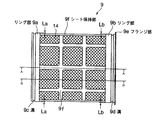
本体容器1への装着方向に窄まるテーパを有する略円筒形状の外部スペーサ9は、その両端にOリングを装着可能な溝9c、9dがそれぞれ形成されたリング部9a、9bと、このリング部9a、9bに対して一体的に形成されたシート保持部9fと、シート保持部9fに接着あるいは融着された、水は通過させるが粒状濾過材7は通過させないシート14とを有する。
The substantially cylindrical
シート保持部9fの外径は、リング部9a、9bに比べて小さくなっており、外部スペーサ9を本体容器1に装着した際、リング部9a側でシート保持部9fの外周と本体容器1の内壁面1aとの間に隙間Laの間隙1bが形成され、一方、リング部9b側で隙間Lbの間隙1bが形成される。なお、隙間La、Lbは同じであってもよいし、あるいは、必要に応じて異なる値とするものであってもよい。なお、これら隙間La、Lbは本体容器1の内壁面1aからシート保持部9fの外周までの距離であり、本体容器1の内壁面1aからシート14の表面までの距離は、図4に示すように概ねLcとなる。
The outer diameter of the
外部スペーサ9は、本体容器1に装着される際、リング部9bの端部に形成されたフランジ部9eが本体容器1の端面1cに当接して位置決めされる。外部スペーサ9は、本体容器1に装着されると、リング部9a、9bが本体容器1の内壁面1aに内接し、溝9c、9dに取り付けられたOリングによりリング部9a、9bと内壁面1aとの間は密封される。
When the
この浄水器の製造工程において、一方が開放した筒状の本体容器1の開放部側を上にし、目皿5、中空糸膜モジュール6、集水管8、外部スペーサ9を挿入した状態で、本体容器1の開放上部から粒状濾過材7を投入充填する。本体容器1の形状は必ずしも限定はされず、例えば多角柱状や円錐台状等の形状とすることも可能であるが、円筒形状とすると、耐圧性や成形性が向上し、かつ外部スペーサ9から集水管8の距離が等しく取れるのでより好ましい。
In the manufacturing process of this water purifier, with the open side of the cylindrical main body container 1 opened on one side facing up, the
本体容器1と底蓋2との結合方法は必ずしも限定はされず、両部材に穴を開けてボルトを通して結合する方法等を用いることができるが、両部材に雄ネジ/雌ネジを形成して嵌合する方法が、部品点数を少なくできるため好ましい。何れの結合方法であっても、粒状濾過材7のネジ部噛み込みによる嵌合不良を防止するために、粒状濾過材7を投入後、その上部に不織布12を載せた上で底蓋2を嵌合させることが好ましい。
The method of connecting the main body container 1 and the
次に、以上のような構成の本実施形態の浄水器における水の流れ方について説明する。 Next, how water flows in the water purifier of the present embodiment having the above-described configuration will be described.
まず、原水は、入水部3より供給され、目皿5を通った後、粒状濾過材7の中を通過する。
First, raw water is supplied from the
その後、図5の粒状濾過材を流れる水の拡大断面図で示すように、外部スペーサ入口部9gまで通過してきた水は、粒状濾過材7の粒径及び外部スペーサ入口部9g開口面積に起因する圧力抵抗によって、外部スペーサ9内の粒状濾過材7を流れる内層流10と外部スペーサ9と本体容器1との間に設けられた間隙1bを通過した後、再び外部スペーサ9内の粒状濾過材7を流れる外層流11に分流される。
Thereafter, as shown in the enlarged cross-sectional view of the water flowing through the granular filter material in FIG. 5, the water that has passed to the outer
分流された内層流10と外層流11は、本体容器1の同心中央部に設けられた集水管8を通過した後、中空糸膜モジュール6を通過し、浄化された濾過水が出水部4から得られる。
The separated inner
このように原水を、外部スペーサ入口部9gにて内層流10と外層流11に分流することにより、外部スペーサ内部の粒状濾過材7を流れる水は、外部スペーサ入口部9gから集水管根元部8aの間には内層流10が流れ、集水管8の中央部から集水管端部8bの間にかけては外層流11が流れ込むことによって、粒状濾過材7は満遍なく有効利用され、水の味を損ねる物質、有機物質及び有害物質等の除去性能を高めることができる。
In this way, by dividing the raw water into the inner
内層流10と外層流11に分流の効果は、本体容器1の配置方向には制限されず、垂直、水平及び斜め方向の何れの場合でも効果がある。また垂直方向の場合において、原水が入水部3より供給される際、原水の流れる方向が垂直上方向であっても垂直下方向の何れであっても効果がある。
The effect of the diversion of the inner
原水を、外部スペーサ入口部9gにて内層流10と外層流11に分流を引き起こされるの要因の一つとして挙げられるのは、粒状濾過材7の粒径によってである。粒状濾過材7の粒径は、#20〜#200メッシュの範囲であればよく、#30〜#180メッシュの範囲が好ましく、#40〜150メッシュの範囲がより好ましい。
One of the factors that cause the raw water to be split into the inner
本発明の浄水器に用いられる、外部スペーサ9と本体容器1との間に設けられた隙間を作るためのシート14は、メッシュ、接着または融着した繊維状シート、不織布、フェルトなどが例示でき、望ましいのは、メッシュ、接着または融着した繊維状シート、不織布が挙げられる。
Examples of the
本発明の浄水器に用いられる粒状濾過材7としては、粉末状活性炭、粒状活性炭、分子吸着樹脂、ゼオライト、モレキュラーシーブ、キレート樹脂、イオン交換樹脂、亜硫酸カルシウム、コーラルサンド、麦飯石、医王石、トルマリンなどが例示でき、これらのうちの1種、あるいは2種以上を用いて使用する方法が挙げられる。望ましくは、粉末状活性炭、粒状活性炭、ゼオライト、モレキュラーシーブ、イオン交換樹脂、亜硫酸カルシウム、これらのうちの1種、あるいは2種以上を用いることで、特に望ましいのは、粉末状活性炭、粒状活性炭を用いる場合である。
As the
この中空糸膜を使用する場合、中空糸膜モジュール6の素材としては特に制限はないが、セルロース系、ポリオレフィン(ポリエチレン、ポリプロピレン)系、ポリビニリデンフロライド(PVDF)、ポリビニルアルコール系、エチレン・ビニルアルコール共重合体、ポリエーテル系、ポリメタクリル酸メチル(PMMA)系、ポリスルフォン系、ポリアクリロニトリル系、ポリ四弗化エチレン(PTFE)系、ポリカーボネイト系、ポリエステル系、ポリアミド系、芳香族ポリアミド系等の各種材料が挙げられる。望ましくは、ポリオレフィン(ポリエチレン、ポリプロピレン)系、ポリビニリデンフロライド(PVDF)を用いることができ、特に望ましくは、ポリオレフィン(ポリエチレン、ポリプロピレン)系を用いる場合である。
When this hollow fiber membrane is used, the material of the hollow
本発明の浄水器を構成する本体容器は、コスト、成形加工性を考慮すると、ABS樹脂、AS樹脂、PP樹脂、PE樹脂、ポリカーボネイト樹脂等のプラスチックで構成することが好ましい。肉厚は、耐圧性を考慮し3mm以上が好ましい。
(第2の実施形態)
図6に本実施形態の浄水器用カートリッジの側断面図を示す。
The main body container constituting the water purifier of the present invention is preferably made of a plastic such as ABS resin, AS resin, PP resin, PE resin, polycarbonate resin, etc. in consideration of cost and moldability. The wall thickness is preferably 3 mm or more in consideration of pressure resistance.
(Second Embodiment)
FIG. 6 shows a side sectional view of the water purifier cartridge of the present embodiment.
本実施形態の浄水器用カートリッジは、水の味を損ねる物質、有機物質及び有害物質等の除去性能を高める目的として、粒状濾過材7の前段に成型状濾過材13が配置されている。なお、本実施形態の浄水器用カートリッジは、成型状濾過材13が設けられた以外の構成は、第1の実施形態で説明した浄水器用カートリッジと同じである。よって、以下の説明では第1の実施形態と同じ符号を用いるものとする。
In the cartridge for water purifier of the present embodiment, the molded filter medium 13 is disposed in front of the
成型状濾過材13は、粉末活性炭、粒状活性炭、繊維状活性炭、イオン交換繊維、ゼオライト、モレキュラーシーブ、キレート樹脂、イオン交換樹脂、亜硫酸カルシウム、コーラルサンド、麦飯石、医王石、トルマリンなどが例示でき、これらのうちの1種、あるいは2種以上を用いて成型し使用する方法が挙げられる。 Examples of the molded filter medium 13 include powdered activated carbon, granular activated carbon, fibrous activated carbon, ion exchange fiber, zeolite, molecular sieve, chelate resin, ion exchange resin, calcium sulfite, coral sand, oat stone, Io stone, tourmaline, and the like. , And a method of molding and using one or more of these.
望ましくは、粉末活性炭、粒状活性炭、繊維状活性炭、イオン交換繊維、ゼオライト、モレキュラーシーブ、キレート樹脂、イオン交換樹脂、亜硫酸カルシウム、これらのうちの1種、あるいは2種以上を用いて成型し使用することで、特に望ましいのは、粉末活性炭、粒状活性炭、繊維状活性炭、イオン交換繊維である。 Desirably, powdered activated carbon, granular activated carbon, fibrous activated carbon, ion exchange fiber, zeolite, molecular sieve, chelate resin, ion exchange resin, calcium sulfite, one or more of these are used. Particularly desirable are powdered activated carbon, granular activated carbon, fibrous activated carbon, and ion exchange fiber.
本実施形態においても、第1の実施形態と同様に、水は内層流10と外層流11とに分流され、粒状濾過材7は満遍なく有効利用され、水の味を損ねる物質、有機物質及び有害物質等の除去性能を高めることができる。
Also in the present embodiment, as in the first embodiment, water is divided into the inner
1 本体容器
1a 内壁面
1b 間隙
1c 端面
2 底蓋
3 入水部
4 出水部
5 目皿
6 中空糸膜モジュール
6a 保持容器
7 粒状濾過材
8 集水管
8a 集水管根元部
8b 集水管端部
9 外部スペーサ
9a、9b リング部
9c、9d 溝
9e フランジ部
9f シート保持部
9g 外部スペーサ入口部
10 内層流
11 外層流
12 不織布
13 成型状濾過材
14 シート
22 不織布
DESCRIPTION OF SYMBOLS 1 Main body container 1a
Claims (11)
前記濾過材の一部を通過した流体の流れを、少なくとも2以上の流れに分流させる分流手段を有し、前記分流手段は、前記分流手段の外周面と前記本体容器の内壁面との間に、分流された流体が通過可能な間隙を形成していることを特徴とする浄水器用カートリッジ。 In the cartridge for the water purifier comprising the filter medium in the main body container,
The flow of fluid passing through a portion of the filtration media, have a shunt means for diverting at least two or more streams, said shunt means, between the outer peripheral surface and the inner wall surface of the main body container of the shunt means , water purifier cartridges, wherein Rukoto diverted fluid to form a can pass gap.
Priority Applications (1)
| Application Number | Priority Date | Filing Date | Title |
|---|---|---|---|
| JP2008182433A JP5081749B2 (en) | 2008-07-14 | 2008-07-14 | Water purifier cartridge |
Applications Claiming Priority (1)
| Application Number | Priority Date | Filing Date | Title |
|---|---|---|---|
| JP2008182433A JP5081749B2 (en) | 2008-07-14 | 2008-07-14 | Water purifier cartridge |
Related Parent Applications (1)
| Application Number | Title | Priority Date | Filing Date |
|---|---|---|---|
| JP2002287563A Division JP4299522B2 (en) | 2002-09-30 | 2002-09-30 | Water purifier cartridge and water purifier |
Publications (2)
| Publication Number | Publication Date |
|---|---|
| JP2008279449A JP2008279449A (en) | 2008-11-20 |
| JP5081749B2 true JP5081749B2 (en) | 2012-11-28 |
Family
ID=40140719
Family Applications (1)
| Application Number | Title | Priority Date | Filing Date |
|---|---|---|---|
| JP2008182433A Expired - Fee Related JP5081749B2 (en) | 2008-07-14 | 2008-07-14 | Water purifier cartridge |
Country Status (1)
| Country | Link |
|---|---|
| JP (1) | JP5081749B2 (en) |
Families Citing this family (1)
| Publication number | Priority date | Publication date | Assignee | Title |
|---|---|---|---|---|
| CN101935113B (en) * | 2010-09-26 | 2012-05-30 | 武汉理工大学 | Method and device thereof for treating cascade adsorbed water by radiating lateral and vertical flows |
Family Cites Families (2)
| Publication number | Priority date | Publication date | Assignee | Title |
|---|---|---|---|---|
| JPH0739863A (en) * | 1993-07-31 | 1995-02-10 | A C M:Kk | Water purifier |
| JP2001353486A (en) * | 2000-06-13 | 2001-12-25 | Matsushita Electric Ind Co Ltd | Water cleaning cartridge |
-
2008
- 2008-07-14 JP JP2008182433A patent/JP5081749B2/en not_active Expired - Fee Related
Also Published As
| Publication number | Publication date |
|---|---|
| JP2008279449A (en) | 2008-11-20 |
Similar Documents
| Publication | Publication Date | Title |
|---|---|---|
| CA2350292C (en) | Water purifying apparatus | |
| RU2596747C2 (en) | Cartridge for purifying water and water treatment plant | |
| JP5999453B2 (en) | Water purification cartridge | |
| CN102105211B (en) | Filtration system having fluid couplings | |
| KR101088862B1 (en) | Combination Filter for Water Purifier | |
| KR101912869B1 (en) | Integrated uf-sediment filter for water purification | |
| JPWO2013089246A1 (en) | Purification system and filter | |
| WO2013039194A1 (en) | Cartridge for water purifier | |
| JP4299522B2 (en) | Water purifier cartridge and water purifier | |
| WO2011159196A1 (en) | Filter module and device for purifying a liquid | |
| JP5081749B2 (en) | Water purifier cartridge | |
| CN103108835B (en) | Water purifying filter cartridge | |
| JP5081750B2 (en) | Water purifier cartridge | |
| CN102612496B (en) | Water purifier cartridge and water purifier | |
| TWI295583B (en) | Water purifier | |
| JP6447239B2 (en) | Water purification cartridge | |
| JP5115485B2 (en) | Water treatment cartridge | |
| JP4255070B2 (en) | Water purification cartridge, method for producing the same, and water purifier provided with the same | |
| KR200296368Y1 (en) | Filter cartridge having doule hollow filled up filter-materials | |
| CN215756703U (en) | Composite filter element end sleeve | |
| JP4187601B2 (en) | Water purifier | |
| JP4646282B2 (en) | Water purifier | |
| CN210367184U (en) | Multiple filter core structure of water purifier | |
| CN214513806U (en) | RO membrane filter core end cover | |
| CN207243601U (en) | Stacked composite filter element |
Legal Events
| Date | Code | Title | Description |
|---|---|---|---|
| A131 | Notification of reasons for refusal |
Free format text: JAPANESE INTERMEDIATE CODE: A131 Effective date: 20110928 |
|
| A521 | Request for written amendment filed |
Free format text: JAPANESE INTERMEDIATE CODE: A523 Effective date: 20111125 |
|
| TRDD | Decision of grant or rejection written | ||
| A01 | Written decision to grant a patent or to grant a registration (utility model) |
Free format text: JAPANESE INTERMEDIATE CODE: A01 Effective date: 20120821 |
|
| A01 | Written decision to grant a patent or to grant a registration (utility model) |
Free format text: JAPANESE INTERMEDIATE CODE: A01 |
|
| A61 | First payment of annual fees (during grant procedure) |
Free format text: JAPANESE INTERMEDIATE CODE: A61 Effective date: 20120903 |
|
| FPAY | Renewal fee payment (event date is renewal date of database) |
Free format text: PAYMENT UNTIL: 20150907 Year of fee payment: 3 |
|
| R151 | Written notification of patent or utility model registration |
Ref document number: 5081749 Country of ref document: JP Free format text: JAPANESE INTERMEDIATE CODE: R151 |
|
| FPAY | Renewal fee payment (event date is renewal date of database) |
Free format text: PAYMENT UNTIL: 20150907 Year of fee payment: 3 |
|
| R250 | Receipt of annual fees |
Free format text: JAPANESE INTERMEDIATE CODE: R250 |
|
| R250 | Receipt of annual fees |
Free format text: JAPANESE INTERMEDIATE CODE: R250 |
|
| R250 | Receipt of annual fees |
Free format text: JAPANESE INTERMEDIATE CODE: R250 |
|
| S533 | Written request for registration of change of name |
Free format text: JAPANESE INTERMEDIATE CODE: R313533 |
|
| R350 | Written notification of registration of transfer |
Free format text: JAPANESE INTERMEDIATE CODE: R350 |
|
| R250 | Receipt of annual fees |
Free format text: JAPANESE INTERMEDIATE CODE: R250 |
|
| R250 | Receipt of annual fees |
Free format text: JAPANESE INTERMEDIATE CODE: R250 |
|
| LAPS | Cancellation because of no payment of annual fees |