以下、本発明の実施形態について図に基づいて説明する。なお、以下の説明では、同一部品には、同一の符号を付している。それらの名称および機能も同じである。したがって、それらについての詳細な説明は繰り返さない。なお、以下の説明において、「上」「下」「前」「後」「左」「右」は、運転席に着座したオペレータを基準とする用語である。
Hereinafter, embodiments of the present invention will be described with reference to the drawings. In the following description, the same parts are denoted by the same reference numerals. Their names and functions are also the same. Therefore, detailed description thereof will not be repeated. In the following description, “upper”, “lower”, “front”, “rear”, “left”, and “right” are terms based on the operator seated in the driver's seat.
<A.全体構成>
図1は、実施形態に基づく作業車両101の外観を説明する図である。図1に示されるように、実施形態に基づく作業車両101として、本例においては、油圧ショベルを例に挙げて説明する。
<A. Overall configuration>
FIG. 1 is a diagram illustrating the appearance of a work vehicle 101 based on the embodiment. As shown in FIG. 1, in this example, a hydraulic excavator will be described as an example of a work vehicle 101 based on the embodiment.
作業車両101は、走行体1と、旋回体3と、作業機4とを主に有している。作業車両101の本体部は、走行体1と旋回体3とにより構成される。本体部には、作業機4が取り付けられている。走行体1は、左右1対の履帯を有している。旋回体3は、走行体1の上部の旋回機構を介して走行体1に旋回可能に装着される。旋回体3は、運転室8等を有する。
The work vehicle 101 mainly includes a traveling body 1, a turning body 3, and a work machine 4. The main body of the work vehicle 101 is composed of a traveling body 1 and a revolving body 3. A work machine 4 is attached to the main body. The traveling body 1 has a pair of left and right crawler belts. The swivel body 3 is attached to the travel body 1 so as to be able to swivel via a swivel mechanism at the top of the travel body 1. The swivel body 3 has a cab 8 or the like.
作業機4は、旋回体3において、上下方向に作動可能に軸支されており、土砂の掘削などの作業を行う。作業機4は、ブーム5と、アーム6と、バケット7とを含む。作業機4は、運転室8の右側に設けられている。
The work machine 4 is pivotally supported in the revolving structure 3 so as to be operable in the vertical direction, and performs work such as excavation of earth and sand. The work machine 4 includes a boom 5, an arm 6, and a bucket 7. The work machine 4 is provided on the right side of the cab 8.
ブーム5は、基部が旋回体3に可動可能に連結されている。アーム6は、ブーム5の先端に可動可能に連結されている。バケット7は、アーム6の先端に可動可能に連結されている。バケット7は、運転室8に対して上下方向に移動可能である。また、バケット7は、運転室8に対して前後方向にも移動可能である。バケット7は、刃先7Aを有する。
The base of the boom 5 is movably connected to the revolving unit 3. The arm 6 is movably connected to the tip of the boom 5. The bucket 7 is movably connected to the tip of the arm 6. The bucket 7 is movable in the vertical direction with respect to the cab 8. Further, the bucket 7 is also movable in the front-rear direction with respect to the cab 8. The bucket 7 has a cutting edge 7A.
<B.運転室内の表示システム>
図2は、運転室8の構成を説明するための図である。詳しくは、図2は、運転室8に備えられた表示システム40を説明するための図である。
<B. Display system in the cab>
FIG. 2 is a diagram for explaining the configuration of the cab 8. Specifically, FIG. 2 is a diagram for explaining the display system 40 provided in the cab 8.
図2に示されるように、運転室8は、窓9と、窓9に設けられたフロントガラス2と、2つのフロントピラー91,92と、表示装置70とを備えている。表示装置70は、投影機71と、レンズ光学系72と、2つの表示ユニット73,74とを含む。窓9は、窓9Aと、窓9Aよりも下側の窓9Bとを含む。フロントガラス2は、窓9Aに設けられたフロントガラス2Aと、窓9Bに設けられたフロントガラス2Bとを含む。
As shown in FIG. 2, the cab 8 includes a window 9, a windshield 2 provided on the window 9, two front pillars 91 and 92, and a display device 70. The display device 70 includes a projector 71, a lens optical system 72, and two display units 73 and 74. The window 9 includes a window 9A and a window 9B below the window 9A. The windshield 2 includes a windshield 2A provided on the window 9A and a windshield 2B provided on the window 9B.
フロントピラー91は、運転室8の運転席に着座したオペレータからみて、左側のフロントピラーである。フロントピラー92は、当該オペレータからみて右側のフロントピラーである。また、フロントピラー92は、フロントピラー91よりも作業機4に近い位置にある。なお、フロントピラー91,92は、「Aピラー」とも称される。
The front pillar 91 is the left front pillar as viewed from the operator seated in the driver's seat of the cab 8. The front pillar 92 is a right front pillar as viewed from the operator. Further, the front pillar 92 is located closer to the work machine 4 than the front pillar 91. The front pillars 91 and 92 are also referred to as “A pillars”.
フロントガラス2A,2Bは、フロントピラー91とフロントピラー92との間に設置されている。なお、図2においては、フロントガラス2が2枚のガラスで構成されている場合を示しているが、フロントガラス2が1枚のガラスで構成されていてもよい。
The windshields 2A and 2B are installed between the front pillar 91 and the front pillar 92. In addition, although the case where the windshield 2 is comprised with two sheets of glass is shown in FIG. 2, the windshield 2 may be comprised with one sheet of glass.
次に、表示システム40の詳細について説明する。
Next, details of the display system 40 will be described.
投影機71は、プロジェクタである。レンズ光学系72は、投影機71と表示ユニット73,74との間に設置されている。レンズ光学系72は、複数のレンズを有する。レンズ光学系72においては、複数のレンズのうちの一部のレンズは、光軸方向に移動可能となっている。
Projector 71 is a projector. The lens optical system 72 is installed between the projector 71 and the display units 73 and 74. The lens optical system 72 has a plurality of lenses. In the lens optical system 72, some of the plurality of lenses are movable in the optical axis direction.
詳細については後述するが、表示ユニット73,74は、オペレータの視野に直接映像を映し出すヘッドアップディスプレイとして機能する。表示ユニット73,74は、作業現場の実景と重ね合わせて作業支援情報を表示する。表示ユニット73,74の各々は、コンバイナを用いて実現することができる。具体的には、表示ユニット73,74の各々は、コンバイナ(図4のコンバイナ731,741を参照)と、当該コンバイナをフロントピラー92に取り付けるための取付部材(図4の取付部材732,742を参照)とを有する。なお、表示ユニット73,74の取付位置については、後述する。
Although details will be described later, the display units 73 and 74 function as a head-up display that directly displays an image in the visual field of the operator. The display units 73 and 74 display work support information superimposed on the actual scene of the work site. Each of the display units 73 and 74 can be realized using a combiner. Specifically, each of the display units 73 and 74 includes a combiner (see the combiners 731 and 741 in FIG. 4) and an attachment member for attaching the combiner to the front pillar 92 (the attachment members 732 and 742 in FIG. 4). Reference). The mounting positions of the display units 73 and 74 will be described later.
各コンバイナは、一部の光を反射し、残りの光を透過するハーフミラーで構成されている。各コンバイナは、投影機71によって投影された映像を運転室8内のオペレータ側に反射するとともに、運転室8の外部からの光を運転室8の内部に透過する。
Each combiner consists of a half mirror that reflects part of the light and transmits the rest of the light. Each combiner reflects the image projected by the projector 71 to the operator side in the cab 8 and transmits light from outside the cab 8 into the cab 8.
このため、表示装置70では、オペレータは、各コンバイナに投影された映像を、運転室8前方の実景に重ねて表示される虚像として捉えることができる。
For this reason, in the display device 70, the operator can grasp the image projected on each combiner as a virtual image displayed superimposed on the real scene in front of the cab 8.
<C.制御系の構成>
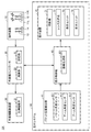
図3は、作業車両101が備える制御系の構成を表したブロック図である。図3に示されるように、作業車両101は、操作装置10と、作業機コントローラ20と、作業機駆動装置30と、表示システム40とを有する。
<C. Configuration of control system>
FIG. 3 is a block diagram showing a configuration of a control system provided in work vehicle 101. As illustrated in FIG. 3, the work vehicle 101 includes an operation device 10, a work machine controller 20, a work machine drive device 30, and a display system 40.
(c1.操作装置10)
操作装置10は、操作部材11L、11Rと、操作検出部12と、走行操作部材13と、走行操作検出部14とを有する。
(C1. Operating device 10)
The operation device 10 includes operation members 11L and 11R, an operation detection unit 12, a travel operation member 13, and a travel operation detection unit 14.
操作部材11L、11Rは、作業機4および旋回体3の操作に用いられる。詳しくは、操作部材11Rは、オペレータがブーム5とバケット7とを操作するために用いられる。操作部材11Lは、オペレータが旋回体3とアーム6とを操作するために用いられる。
The operation members 11L and 11R are used for the operation of the work machine 4 and the swing body 3. Specifically, the operation member 11 </ b> R is used for an operator to operate the boom 5 and the bucket 7. The operation member 11L is used for an operator to operate the swing body 3 and the arm 6.
操作検出部12は、操作部材11L、11Rに対するオペレータの操作を検出する。
The operation detection unit 12 detects an operator's operation on the operation members 11L and 11R.
走行操作部材13は、オペレータが作業車両101の走行を操作するために用いられる。走行操作検出部14は、走行操作部材13に対するオペレータの操作を検出する。作業車両101は、走行操作部材13の操作量に応じた速度で移動する。
The traveling operation member 13 is used for an operator to operate the traveling of the work vehicle 101. The travel operation detection unit 14 detects an operator's operation on the travel operation member 13. The work vehicle 101 moves at a speed corresponding to the operation amount of the travel operation member 13.
(c2.作業機コントローラ20)
作業機コントローラ20は、記憶部21と、演算部22とを有している。記憶部21は、RAM(Random Access Memory)およびROM(Read Only Memory)等のメモリで構成される。演算部22は、CPU(Central Processing Unit)等の演算処理装置で構成される。
(C2. Work machine controller 20)
The work machine controller 20 includes a storage unit 21 and a calculation unit 22. The storage unit 21 includes a memory such as a RAM (Random Access Memory) and a ROM (Read Only Memory). The calculation unit 22 is configured by a calculation processing device such as a CPU (Central Processing Unit).
作業機コントローラ20は、主として、作業機4の動作と旋回体3の旋回とを制御する。詳しくは、作業機コントローラ20は、操作部材11L、11Rの操作に応じて、作業機4および旋回体3を動作させるための制御信号を生成する。作業機コントローラ20は、生成した制御信号を作業機駆動装置30に出力する。
The work machine controller 20 mainly controls the operation of the work machine 4 and the turning of the revolving structure 3. Specifically, the work machine controller 20 generates a control signal for operating the work machine 4 and the swing body 3 in accordance with the operation of the operation members 11L and 11R. The work machine controller 20 outputs the generated control signal to the work machine drive device 30.
(c3.作業機駆動装置30)
作業機駆動装置30は、比例電磁弁31を有している。比例電磁弁31は、作業機コントローラ20からの制御信号に基づいて動作する。比例電磁弁31は、制御信号に応じた流量の作動油を、油圧シリンダおよび旋回モータに供給する。これにより、作業機4が動作し、旋回体3が旋回する。
(C3. Work implement drive device 30)
The work machine drive device 30 has a proportional solenoid valve 31. The proportional solenoid valve 31 operates based on a control signal from the work machine controller 20. The proportional solenoid valve 31 supplies hydraulic oil at a flow rate corresponding to the control signal to the hydraulic cylinder and the swing motor. Thereby, the working machine 4 operates and the revolving structure 3 turns.
(c4.表示システム40)
表示システム40は、バケット位置検出部41と、表示制御部43と、表示装置70とを有する。
(C4. Display system 40)
The display system 40 includes a bucket position detection unit 41, a display control unit 43, and a display device 70.
バケット位置検出部41は、バケット角度センサ411と、アーム角度センサ412と、ブーム角度センサ413とを有する。
The bucket position detection unit 41 includes a bucket angle sensor 411, an arm angle sensor 412, and a boom angle sensor 413.
バケット角度センサ411は、バケット7の所定の基準位置からの相対角度を検出する。アーム角度センサ412は、アーム6の所定の基準位置からの相対角度を検出する。ブーム角度センサ413は、ブーム5の所定の基準位置からの相対角度を検出する。
The bucket angle sensor 411 detects a relative angle of the bucket 7 from a predetermined reference position. The arm angle sensor 412 detects a relative angle of the arm 6 from a predetermined reference position. The boom angle sensor 413 detects a relative angle of the boom 5 from a predetermined reference position.
バケット位置検出部41は、検出された3つの相対角度の情報に基づき、作業車両本体に対するバケット7の位置を検出する。詳しくは、車体座標系におけるバケット7の位置を検出する。バケット位置検出部41は、バケット7の位置として、たとえば、バケット7の刃先7Aの位置を検出する。
The bucket position detection unit 41 detects the position of the bucket 7 with respect to the work vehicle main body based on the detected information on the three relative angles. Specifically, the position of the bucket 7 in the vehicle body coordinate system is detected. The bucket position detection unit 41 detects the position of the cutting edge 7 </ b> A of the bucket 7 as the position of the bucket 7, for example.
表示制御部43は、オペレータによる作業機4の操作(作業)を支援するための情報(作業支援情報)等の各種の画像を、表示ユニット73,74に表示させる。表示制御部43は、検出されたバケット7の位置を利用した作業支援情報(たとえば、設計地形と刃先7Aとの距離を表すライトバー)を、表示ユニット73,74に表示させる。表示制御部43についてさらに詳しく説明すると、以下のとおりである。
The display control unit 43 causes the display units 73 and 74 to display various images such as information (work support information) for supporting the operation (work) of the work machine 4 by the operator. The display control unit 43 causes the display units 73 and 74 to display work support information using the detected position of the bucket 7 (for example, a light bar indicating the distance between the design landform and the cutting edge 7A). The display control unit 43 will be described in further detail as follows.
表示制御部43は、画像生成部431を有する。画像生成部431は、表示ユニット73,74に表示する画像を生成する。画像生成部431は、車速計、エンジン回転計、燃料計、油温計等を表した画像を生成する。さらに、画像生成部431は、複数の作業支援情報を表した画像を生成する。
The display control unit 43 includes an image generation unit 431. The image generation unit 431 generates an image to be displayed on the display units 73 and 74. The image generation unit 431 generates an image representing a vehicle speedometer, an engine tachometer, a fuel gauge, an oil temperature gauge, and the like. Further, the image generation unit 431 generates an image representing a plurality of work support information.
詳しくは、画像生成部431は、作業車両101の動力系を制御するコントローラ(図示せず)と接続されている。画像生成部431は、各種のセンサによって検知された情報およびコントローラによる制御内容に関する情報などを受信する。画像生成部431は、当該受信された情報に基づいて、表示ユニット73,74に表示させる画像を生成する。
Specifically, the image generation unit 431 is connected to a controller (not shown) that controls the power system of the work vehicle 101. The image generation unit 431 receives information detected by various sensors, information related to control contents by the controller, and the like. The image generation unit 431 generates an image to be displayed on the display units 73 and 74 based on the received information.
表示装置70は、上述したように、投影機71と、レンズ光学系72と、表示ユニット73,74とを備える。
As described above, the display device 70 includes the projector 71, the lens optical system 72, and the display units 73 and 74.
<D.表示ユニット>
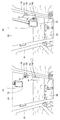
図4は、表示ユニット73,74の取付位置を表した図である。図4を参照して、表示ユニット73および表示ユニット74は、互いに異なる位置においてフロントピラーに沿って設けられている。表示ユニット73および表示ユニット74の各々は、表示ユニット73が表示ユニット74よりも上方に位置するように、フロントピラー92に沿って設置されている。
<D. Display unit>
FIG. 4 is a diagram showing the attachment positions of the display units 73 and 74. Referring to FIG. 4, display unit 73 and display unit 74 are provided along the front pillar at different positions. Each of the display unit 73 and the display unit 74 is installed along the front pillar 92 so that the display unit 73 is located above the display unit 74.
詳しくは、表示ユニット73は、コンバイナ731と、取付部材732とを備える。コンバイナ731は、取付部材732によって、フロントピラー92に取り付けられている。表示ユニット74は、コンバイナ741と、取付部材742とを備える。コンバイナ741は、取付部材742によって、フロントピラー92に取り付けられている。また、コンバイナ731,741は、外縁を囲う枠を有していない。
Specifically, the display unit 73 includes a combiner 731 and an attachment member 732. The combiner 731 is attached to the front pillar 92 by an attachment member 732. The display unit 74 includes a combiner 741 and an attachment member 742. The combiner 741 is attached to the front pillar 92 by an attachment member 742. The combiners 731 and 741 do not have a frame surrounding the outer edge.
さらに詳しくは、取付部材732は、取付部材742よりも上方の位置で、フロントピラー92に取り付けられている。これにより、コンバイナ731は、フロントピラー92に沿ってコンバイナ741よりも上方に配置され得る。
More specifically, the attachment member 732 is attached to the front pillar 92 at a position above the attachment member 742. Accordingly, the combiner 731 can be disposed above the combiner 741 along the front pillar 92.
以上のように、ヘッドアップディスプレイである2つの表示ユニット73,74は、フロントピラー92に沿って上下方向に並んで設置されている。それゆえ、ヘッドアップディスプレイによって、運転室8から見て前方の視認性が低下することを低減できる。特に、フロントガラス2の中央部の視認性は、低下することはない。したがって、作業車両101は、作業現場の実景等の視認性に優れる。
As described above, the two display units 73 and 74 that are head-up displays are installed along the front pillar 92 in the vertical direction. Therefore, the head-up display can reduce a decrease in front visibility when viewed from the cab 8. In particular, the visibility of the central portion of the windshield 2 does not decrease. Therefore, the work vehicle 101 is excellent in visibility such as a real scene at the work site.
さらに、ヘッドアップディスプレイがフロントピラー91よりも作業機4に近いフロントピラー92に沿って配置されているため、ヘッドアップディスプレイが左側のフロントピラー91に沿って配置されている構成に比べて、作業機4の操作時におけるオペレータの視線の移動量を少なくすることができる。また、表示ユニット73と表示ユニット74とが互いに異なる位置に設置(詳しくは、上下方向に並んで設置)されるため、オペレータは、2つの表示ユニット73,73で作業支援情報等の各種の情報を確認することが可能となる。
Furthermore, since the head-up display is disposed along the front pillar 92 closer to the work machine 4 than the front pillar 91, the head-up display is operated in comparison with the configuration in which the head-up display is disposed along the left front pillar 91. The amount of movement of the line of sight of the operator when operating the machine 4 can be reduced. In addition, since the display unit 73 and the display unit 74 are installed at different positions (specifically, installed side by side in the vertical direction), the operator can use the two display units 73 and 73 to perform various information such as work support information. Can be confirmed.
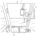
図5は、コンバイナ731,741の角度調整機能を説明するための図である。図5に示すように、表示ユニット73,74の各々は、水平面に対する表示面の傾斜角度を調整する機能(各々の表示面を前後方向に傾斜可能な角度調整機能)を有する。詳しくは、取付部材732,742は、コンバイナ731,741を図の矢印の方向に回転させるための機構を有している。表示ユニット73は、矢印に示すように、コンバイナ731の上端および下端をオペレータに対して前後方向に回動させることができる。同様に、表示ユニット74も、矢印に示すように、コンバイナ741の上端および下端をオペレータに対して前後方向に回動させることができる。
FIG. 5 is a diagram for explaining the angle adjustment function of the combiners 731 and 741. As shown in FIG. 5, each of the display units 73 and 74 has a function of adjusting the tilt angle of the display surface with respect to the horizontal plane (an angle adjusting function capable of tilting each display surface in the front-rear direction). Specifically, the attachment members 732 and 742 have a mechanism for rotating the combiners 731 and 741 in the direction of the arrows in the figure. As indicated by the arrows, the display unit 73 can rotate the upper and lower ends of the combiner 731 in the front-rear direction with respect to the operator. Similarly, the display unit 74 can also rotate the upper end and lower end of the combiner 741 in the front-rear direction with respect to the operator, as indicated by the arrows.
このように、表示ユニット73,74は、コンバイナ731,741の垂直角度調整が可能となる。それゆえ、オペレータに適した角度に各表示面の垂直角度を調整可能となる。
Thus, the display units 73 and 74 can adjust the vertical angle of the combiners 731 and 741. Therefore, the vertical angle of each display surface can be adjusted to an angle suitable for the operator.
ところで、表示ユニット73の表示面と水平面との間の角度は、表示ユニット74の表示面と水平面との間の角度よりも大きく設定されていることが好ましい。詳しくは、上側のコンバイナ731の主面とが水平面Hとの間の角度θ1は、下側のコンバイナ741の主面と水平面Hとの間の角度θ2よりも大きく設定(θ1>θ2)されていることが好ましい。なお、「主面」とは、レンズ光学系72からの映像が投影される面である。
Incidentally, the angle between the display surface of the display unit 73 and the horizontal plane is preferably set to be larger than the angle between the display surface of the display unit 74 and the horizontal plane. Specifically, the angle θ1 between the main surface of the upper combiner 731 and the horizontal plane H is set larger than the angle θ2 between the main surface of the lower combiner 741 and the horizontal plane H (θ1> θ2). Preferably it is. The “main surface” is a surface onto which an image from the lens optical system 72 is projected.
この構成によれば、表示ユニット73よりも下方の表示ユニット74の表示面(コンバイナ741の主面)が、表示ユニット73の表示面(コンバイナ731の主面)よりも寝た状態となる。したがって、表示ユニット73の表示面と水平面Hとの間の角度θ1が表示ユニット74の表示面と水平面Hとの間の角度θ2よりも小さい場合(θ1<θ2)に比べて、表示ユニット73,74における表示内容(作業支援情報等)の視認性を良くすることができる。
According to this configuration, the display surface of the display unit 74 below the display unit 73 (the main surface of the combiner 741) is in a state of sleeping than the display surface of the display unit 73 (the main surface of the combiner 731). Accordingly, the display unit 73, the angle θ1 between the display surface of the display unit 73 and the horizontal plane H is smaller than the angle θ2 between the display surface of the display unit 74 and the horizontal plane H (θ1 <θ2). The visibility of the display content (work support information etc.) in 74 can be improved.
図6は、表示ユニット73,74の取付位置の詳細を説明するための図である。図6に示すように、表示ユニット73は、表示ユニット74から距離dだけ離れて設置される。詳しくは、表示ユニット73のフロントピラー92への取付位置と表示ユニット74のフロントピラー92への取付位置とは、距離dだけ離れている。
FIG. 6 is a diagram for explaining the details of the mounting positions of the display units 73 and 74. As shown in FIG. 6, the display unit 73 is installed at a distance d from the display unit 74. Specifically, the mounting position of the display unit 73 to the front pillar 92 and the mounting position of the display unit 74 to the front pillar 92 are separated by a distance d.
また、作業車両101では、表示ユニット73,74の表示面の横幅Wは、距離dよりも狭い。詳しくは、コンバイナ731,741の横幅Wは、表示ユニット73の取付位置と表示ユニット74の取付位置との間隔(距離d)よりも短い。このような構成によれば、横幅Wが、表示ユニット73の取付位置と表示ユニット74の取付位置との間隔(距離d)よりも広い構成(W>d)に比べて、運転室から見て前方の視認性(とりわけ、フロントガラス2の中央部の視認性)を高めることができる。
In the work vehicle 101, the horizontal width W of the display surface of the display units 73 and 74 is narrower than the distance d. Specifically, the width W of the combiners 731 and 741 is shorter than the distance (distance d) between the mounting position of the display unit 73 and the mounting position of the display unit 74. According to such a configuration, the lateral width W is viewed from the operator's cab as compared with a configuration (W> d) wider than the interval (distance d) between the mounting position of the display unit 73 and the mounting position of the display unit 74. The front visibility (particularly, the visibility of the central portion of the windshield 2) can be improved.
さらに、上述したように、コンバイナ731,741の各々は表示面の外縁を囲む枠を有していないため、表示面の外縁を囲む枠(ベゼル)を有するようなハードウェア構成に比べて、表示領域を広くすることができる。
Furthermore, as described above, since each of the combiners 731 and 741 does not have a frame surrounding the outer edge of the display surface, the display is compared with a hardware configuration having a frame (bezel) surrounding the outer edge of the display surface. The area can be widened.
なお、作業機4、運転室8、フロントピラー92、表示ユニット73、表示ユニット74、コンバイナ731,741、取付部材732,742は、それぞれ本発明の「作業機」、「運転室」、「フロントピラー」、「第1の表示部」、「第2の表示部」、「コンバイナ」、「取付部材」の一例である。
In addition, the work machine 4, the cab 8, the front pillar 92, the display unit 73, the display unit 74, the combiners 731 and 741, and the mounting members 732 and 742 are the “work machine”, “cab”, and “front” of the present invention, respectively. It is an example of “pillar”, “first display section”, “second display section”, “combiner”, and “mounting member”.
<E.表示例>
表示システム40は、複数の表示モードを有する。表示システム40は、表示モードの選択をオペレータから受け付ける。表示システム40は、受け付けた表示モードに従い、表示ユニット73,74の表示内容を制御する。
<E. Display example>
The display system 40 has a plurality of display modes. The display system 40 receives a display mode selection from the operator. The display system 40 controls the display contents of the display units 73 and 74 according to the received display mode.
以下では、このような複数の表示モードを有する場合に、表示ユニット73,74で表示される表示内容について説明する。
Hereinafter, the display contents displayed on the display units 73 and 74 in the case of having such a plurality of display modes will be described.
(e1.第1の表示例)
図7は、第1の表示例を説明するための図である。図7の状態(A),(B)に示すように、表示制御部43は、表示ユニット73および表示ユニット74に同時に作業支援情報を表示させる。
(E1. First display example)
FIG. 7 is a diagram for explaining the first display example. As shown in the states (A) and (B) of FIG. 7, the display control unit 43 causes the display unit 73 and the display unit 74 to simultaneously display work support information.
詳しくは、第1の表示モードが設定されている場合には、図7の状態(A)に示すとおり、表示制御部43は、表示ユニット73および表示ユニット74に同一の作業支援情報を表示させる。たとえば、表示制御部43は、表示ユニット73に第1の作業支援情報を表示させ、表示ユニット74に第1の作業支援情報と同一情報である第2の作業支援情報を表示させる。また、第2の表示モードが設定されている場合には、図7の状態(B)に示すとおり、表示制御部43は、表示ユニット73および表示ユニット74に異なる作業支援情報を表示させる。たとえば、表示制御部43は、表示ユニット73に第1の作業支援情報を表示させ、表示ユニット74に第1の作業支援情報とは異なる情報である第2の作業支援情報を表示させる。
Specifically, when the first display mode is set, the display control unit 43 causes the display unit 73 and the display unit 74 to display the same work support information as shown in the state (A) of FIG. . For example, the display control unit 43 causes the display unit 73 to display first work support information, and causes the display unit 74 to display second work support information that is the same information as the first work support information. When the second display mode is set, the display control unit 43 causes the display unit 73 and the display unit 74 to display different work support information as shown in the state (B) of FIG. For example, the display control unit 43 causes the display unit 73 to display first work support information, and causes the display unit 74 to display second work support information that is different from the first work support information.
図7の状態(A)には、上記第1の作業支援情報および第1の作業支援情報と同一情報である第2の作業支援情報として、正対コンパス(表示ユニット73,74における上側の画像)と、設計地形と刃先との断面(表示ユニット73,74における下側の画像)とを表示させた例が示されている。なお、正対コンパスは、作業車両101が設計地形データと正対した状態にあるか否かを表す。
In the state (A) in FIG. 7, the first work support information and the second work support information that is the same information as the first work support information are used as the front compass (the upper image in the display units 73 and 74. ) And a cross section of the design terrain and the cutting edge (lower images in the display units 73 and 74) are displayed. The facing compass represents whether the work vehicle 101 is in a state of facing the design terrain data.
また、図7の状態(B)には、上記第1の作業支援情報とは異なる情報である上記第2の作業支援情報として、ライトバー(表示ユニット74における左側の画像)と、設計地形と刃先7Aとの距離を表す距離情報(表示ユニット74における右側の画像)とを表示させた例が示されている。ライトバーは、設計地形と刃先7Aとの距離を図形として表したものである。
In the state (B) of FIG. 7, as the second work support information that is different from the first work support information, the light bar (the left image in the display unit 74), the design landform, An example is shown in which distance information (a right image on the display unit 74) representing the distance to the blade edge 7A is displayed. The light bar represents the distance between the design topography and the cutting edge 7A as a figure.
以上のように、第1の表示モードが設定されている場合には、表示制御部43は、表示ユニット73と表示ユニット74とに同一の作業支援情報を同時に表示させる。この構成によれば、オペレータは、作業支援情報を確認する際、表示ユニット73および表示ユニット74のうち、視線移動量が少ない方の表示を確認するだけで情報を得ることができる。
As described above, when the first display mode is set, the display control unit 43 causes the display unit 73 and the display unit 74 to simultaneously display the same work support information. According to this configuration, when confirming the work support information, the operator can obtain information only by confirming the display of the display unit 73 and the display unit 74 that has the smaller eye movement amount.
また、上述したように、第2の表示モードが設定されている場合には、表示制御部43は、表示ユニット73と表示ユニット74とに異なる作業支援情報を同時に表示させる。この構成によれば、表示システム40は、第1の表示モードが設定されている場合よりも多くの種別の作業支援情報を表示することが可能となる。したがって、オペレータは、第1の表示モードが設定されている場合よりも多くの情報を、同時に視認することが可能となる。
As described above, when the second display mode is set, the display control unit 43 causes the display unit 73 and the display unit 74 to simultaneously display different work support information. According to this configuration, the display system 40 can display more types of work support information than when the first display mode is set. Therefore, the operator can view more information at the same time than when the first display mode is set.
(e2.第2の表示例)
図8は、第2の表示例を説明するための図である。図8の状態(A),(B)に示すように、表示制御部43は、表示ユニット73および表示ユニット74のうちのいずれか一方に作業支援情報を表示させる。
(E2. Second display example)
FIG. 8 is a diagram for explaining a second display example. As shown in the states (A) and (B) of FIG. 8, the display control unit 43 displays work support information on one of the display unit 73 and the display unit 74.
詳しくは、第3の表示モードが設定されている場合には、図8の状態(A)に示すとおり、表示制御部43は、表示ユニット73および表示ユニット74のうちの表示ユニット73のみに作業支援情報を表示させる。また、第4の表示モードが設定されている場合には、図8の状態(B)に示すとおり、表示制御部43は、表示ユニット73および表示ユニット74のうちの表示ユニット74のみに作業支援情報を表示させる。
Specifically, when the third display mode is set, the display control unit 43 operates only on the display unit 73 of the display unit 73 and the display unit 74 as shown in the state (A) of FIG. Display support information. When the fourth display mode is set, the display control unit 43 supports the display unit 73 and the display unit 74 among the display units 74 only as shown in the state (B) of FIG. Display information.
なお、図8の状態(A),(B)にも示したように、第3の表示モードが設定されている場合に表示ユニット73に表示される作業支援情報と、第4の表示モードが設定されている場合に表示ユニット74に表示される作業支援情報とは、同一(詳しくは、同一種別の情報)である。
As shown in the states (A) and (B) of FIG. 8, when the third display mode is set, the work support information displayed on the display unit 73 and the fourth display mode are displayed. The work support information displayed on the display unit 74 when set is the same (specifically, the same type of information).
このように、表示制御部43は、第3の表示モードまたは第4の表示モードが設定されている場合、表示対象である作業支援情報を、表示ユニット73および表示ユニット74のうちいずれか一方に表示させる。このような構成によれば、表示システム40は、表示システム40で消費される消費電力の低減を図ることが可能となる。
As described above, when the third display mode or the fourth display mode is set, the display control unit 43 sets the work support information that is a display target to one of the display unit 73 and the display unit 74. Display. According to such a configuration, the display system 40 can reduce power consumption consumed by the display system 40.
(e3.第3の表示例)
図9は、第3の表示例を説明するための図である。図9の状態(A),(B)に示すとおり、表示制御部43は、バケット7の位置に応じて、作業支援情報を表示ユニット73に表示させるか、あるいは表示ユニット74に表示させるかを決定する。
(E3. Third display example)
FIG. 9 is a diagram for explaining a third display example. As shown in the states (A) and (B) of FIG. 9, the display control unit 43 determines whether the work support information is displayed on the display unit 73 or the display unit 74 according to the position of the bucket 7. decide.
表示制御部43は、バケット7の位置が予め定められた位置よりも高い場合には、表示ユニット73および表示ユニット74のうちの表示ユニット73のみに作業支援情報を表示させる。また、表示制御部43は、バケット7の位置が予め定められた位置よりも低い場合には、表示ユニット73および表示ユニット74のうちの表示ユニット74のみに作業支援情報を表示させる。なお、バケット7の位置は、典型的には、バケット7の刃先7Aの位置として特定される。
When the position of the bucket 7 is higher than a predetermined position, the display control unit 43 displays the work support information only on the display unit 73 of the display unit 73 and the display unit 74. In addition, when the position of the bucket 7 is lower than a predetermined position, the display control unit 43 displays the work support information only on the display unit 74 of the display unit 73 and the display unit 74. The position of the bucket 7 is typically specified as the position of the cutting edge 7A of the bucket 7.
詳しくは、表示制御部43は、バケット7の位置が上記の予め定められた位置よりも高い位置から低い位置へと遷移した場合、作業支援情報を表示する表示ユニットを、表示ユニット73から下方の表示ユニット74に切り替える。また、表示制御部43は、バケット7の位置が上記の予め定められた位置よりも低い位置から高い位置へと遷移した場合、作業支援情報を表示する表示ユニットを、表示ユニット74から上方の表示ユニット73に切り替える。
Specifically, when the position of the bucket 7 transitions from a position higher than the predetermined position to a position lower than the predetermined position, the display control unit 43 changes the display unit that displays the work support information from the display unit 73 to the lower side. Switch to the display unit 74. Further, when the position of the bucket 7 transitions from a position lower than the predetermined position to a higher position, the display control unit 43 displays a display unit that displays work support information from the display unit 74 upward. Switch to unit 73.
このような構成によれば、オペレータが作業支援情報を確認する際、バケットが所定の位置よりも高い位置にある場合に表示ユニット74のみに作業支援情報が表示される構成に比べて、オペレータの視線移動を少なくすることができる。また、オペレータが作業支援情報を確認する際、バケットが所定の位置よりも低い位置にある場合に表示ユニット73のみに作業支援情報が表示される構成に比べて、オペレータの視線移動を少なくすることができる。
According to such a configuration, when the operator confirms the work support information, the work support information is displayed only on the display unit 74 when the bucket is at a position higher than a predetermined position. Gaze movement can be reduced. In addition, when the operator confirms the work support information, the operator's line-of-sight movement is reduced compared to a configuration in which the work support information is displayed only on the display unit 73 when the bucket is at a position lower than a predetermined position. Can do.
<F.変形例>
(1)表示ユニット73および表示ユニット74の各々は、フロントピラー92の延伸方向に沿ってスライド可能にフロントピラー92に取り付けられていてもよい。
<F. Modification>
(1) Each of the display unit 73 and the display unit 74 may be attached to the front pillar 92 so as to be slidable along the extending direction of the front pillar 92.
図10は、表示ユニット73,74のスライドを説明するための図である。図10に示すように、オペレータは、表示ユニット73の取付部材732をフロントピラー92の延伸方向に沿ってスライドさせることにより、コンバイナ731をフロントピラー92の延伸方向に沿ってスライドさせることができる。また、オペレータは、表示ユニット74の取付部材742をフロントピラー92の延伸方向に沿ってスライドさせることにより、コンバイナ741をフロントピラー92の延伸方向に沿ってスライドさせることができる。
FIG. 10 is a diagram for explaining the slide of the display units 73 and 74. As shown in FIG. 10, the operator can slide the combiner 731 along the extending direction of the front pillar 92 by sliding the attachment member 732 of the display unit 73 along the extending direction of the front pillar 92. Further, the operator can slide the combiner 741 along the extending direction of the front pillar 92 by sliding the mounting member 742 of the display unit 74 along the extending direction of the front pillar 92.
このような構成によれば、オペレータは、表示ユニット73よび表示ユニット74の各々の取付位置を、自身の好みの高さに設定することができる。
According to such a configuration, the operator can set the mounting position of each of the display unit 73 and the display unit 74 to his / her preferred height.
なお、このような構成の場合、表示ユニット73,74の取付位置が変化すると、当該変化に応じて、作業支援情報等の画像の投影位置を変化させる必要がある。このような投影位置の制御は、オペレータ操作に基づいて行ってもよいし、あるいは、自動で行われてもよい。
In the case of such a configuration, when the mounting position of the display units 73 and 74 changes, it is necessary to change the projection position of an image such as work support information according to the change. Such control of the projection position may be performed based on an operator operation or may be performed automatically.
投影位置の制御を自動で行う場合には、表示ユニット73,74の取付位置の情報(詳しくは、コンバイナ731,741の座標)を表示制御部43が取得し、かつ、取得した情報に基づいて作業支援情報等の画像の投影位置を制御するように、表示システム40を構成すればよい。なお、カメラ(図示せず)による撮像によって得られた画像データの解析に基づいて、上記取付位置の情報(たとえば、高さ情報)を取得してもよいし、センサ(図示せず)によって、上記取付位置の情報を取得してもよい。表示ユニット73,74の取付位置の情報の取得方法は特に限定されるものではない。
When the projection position is automatically controlled, the display control unit 43 acquires information on the mounting positions of the display units 73 and 74 (specifically, the coordinates of the combiners 731 and 741), and based on the acquired information. The display system 40 may be configured to control the projection position of an image such as work support information. In addition, based on the analysis of the image data obtained by imaging with a camera (not shown), information on the mounting position (for example, height information) may be acquired, or by a sensor (not shown), You may acquire the information of the said attachment position. The acquisition method of the information of the attachment position of the display units 73 and 74 is not specifically limited.
(2)表示ユニット73および表示ユニット74の各々は、フロントピラー92に対して着脱可能にフロントピラー92に取り付けられていることが好ましい。このような構成によれば、たとえば1つの表示ユニットのみを有する構成とすることもできる。また、フロントピラー92に対して着脱可能でない構成に比べて、表示ユニットに対するメンテナンスの点においても優れている。
(2) Each of the display unit 73 and the display unit 74 is preferably attached to the front pillar 92 so as to be detachable from the front pillar 92. According to such a structure, it can also be set as the structure which has only one display unit, for example. Further, compared to a configuration in which the front pillar 92 is not detachable, the display unit is superior in terms of maintenance.
(3)上記の実施の形態においては、作業車両101が2つの表示ユニットを備える構成を例挙げて説明した。具体的には、表示システム40が2つのコンバイナ731,741を備える構成を例に挙げて説明した。しかしながら、表示システムの数およびコンバイナの数は、2つには限定されず、3つ以上であってもよい。
(3) In the above embodiment, the configuration in which the work vehicle 101 includes two display units has been described as an example. Specifically, the configuration in which the display system 40 includes two combiners 731 and 741 has been described as an example. However, the number of display systems and the number of combiners are not limited to two and may be three or more.
(4)上記においては、表示ユニット73,74が、それぞれ、コンバイナ731,741を備えている構成を例に挙げて説明したが、これに限定されるものではない。
(4) In the above description, the display units 73 and 74 have been described by way of example of the configuration including the combiners 731 and 741, respectively. However, the present invention is not limited to this.
たとえば、オペレータが、虚像ではなく、フィルムに投影された像を視認するような構成としてもよい。具体的には、表示ユニット73の代わりに、運転室8に入射する外光を透過する第1のフィルムを用い、表示ユニット74の代わりに、運転室8に入射する外光を透過する第2のフィルムを用いてもよい。
For example, it may be configured such that an operator visually recognizes an image projected on a film instead of a virtual image. Specifically, instead of the display unit 73, a first film that transmits external light incident on the cab 8 is used, and a second film that transmits external light incident on the cab 8 is used instead of the display unit 74. The film may be used.
なお、第1のフィルムおよび第2のフィルムの各々は、第1のフィルムが第2のフィルムよりも上方に位置するように、フロントピラー92に沿って設置される。この場合、第1のフィルムと、第2のフィルムとが、ヘッドアップディスプレイとして機能する。なお、第1のフィルム、第2のフィルムは、本発明の「第1の表示部」、「第2の表示部」の一例である。
Note that each of the first film and the second film is installed along the front pillar 92 so that the first film is positioned above the second film. In this case, the first film and the second film function as a head-up display. The first film and the second film are examples of the “first display portion” and the “second display portion” in the present invention.
このような構成の場合、運転室8のオペレータは、第1のフィルムまたは第2のフィルムを透して、作業機4を含む作業現場の実景を目視することができる。それゆえ、このような構成の場合にも、ヘッドアップディスプレイによって、フロントガラスの中央部の視認性が低下することはない。したがって、作業車両101は、作業現場の実景等の視認性に優れる。
In the case of such a configuration, the operator of the operator cab 8 can see the actual scene of the work site including the work machine 4 through the first film or the second film. Therefore, even in such a configuration, the visibility of the central portion of the windshield is not deteriorated by the head-up display. Therefore, the work vehicle 101 is excellent in visibility such as a real scene at the work site.
また、オペレータが、虚像ではなく、ディスプレイに表示された像を直接視認するような構成としてもよい。具体的には、表示ユニット73の代わりに、運転室8に入射する外光を透過する透明の第1のディスプレイ(たとえば、透過型の液晶ディスプレイ)を用い、表示ユニット74の代わりに、運転室8に入射する外光を透過する透明の第2のディスプレイを用いてもよい。
Further, the operator may directly view the image displayed on the display instead of the virtual image. Specifically, instead of the display unit 73, a transparent first display (for example, a transmissive liquid crystal display) that transmits external light incident on the cab 8 is used, and instead of the display unit 74, the cab is used. A transparent second display that transmits external light incident on the light 8 may be used.
なお、第1のディスプレイおよび第2のディスプレイの各々は、第1のディスプレイが第2のディスプレイよりも上方に位置するように、フロントピラー92に沿って設置される。この場合、第1のディスプレイと、第2のディスプレイが、ヘッドアップディスプレイとして機能する。なお、第1のディスプレイ、第2のディスプレイは、本発明の「第1の表示部」、「第2の表示部」の一例である。
Note that each of the first display and the second display is installed along the front pillar 92 so that the first display is located above the second display. In this case, the first display and the second display function as a head-up display. The first display and the second display are examples of the “first display unit” and the “second display unit” in the present invention.
この場合も、コンバイナ731,741、第1のフィルムおよび第2のフィルムを用いる場合と同様に、ヘッドアップディスプレイによって、フロントガラスの中央部の視認性が低下することはない。したがって、作業車両101は、作業現場の実景等の視認性に優れる。
Also in this case, the visibility of the central portion of the windshield is not lowered by the head-up display, as in the case of using the combiners 731 and 741, the first film and the second film. Therefore, the work vehicle 101 is excellent in visibility such as a real scene at the work site.
今回開示された実施の形態は例示であって、上記内容のみに制限されるものではない。本発明の範囲は請求の範囲によって示され、請求の範囲と均等の意味および範囲内でのすべての変更が含まれることが意図される。
The embodiment disclosed this time is an example, and is not limited to the above contents. The scope of the present invention is defined by the terms of the claims, and is intended to include any modifications within the scope and meaning equivalent to the terms of the claims.