WO2017141585A1 - Vehicle risk avoidance device - Google Patents
Vehicle risk avoidance device Download PDFInfo
- Publication number
- WO2017141585A1 WO2017141585A1 PCT/JP2017/000800 JP2017000800W WO2017141585A1 WO 2017141585 A1 WO2017141585 A1 WO 2017141585A1 JP 2017000800 W JP2017000800 W JP 2017000800W WO 2017141585 A1 WO2017141585 A1 WO 2017141585A1
- Authority
- WO
- WIPO (PCT)
- Prior art keywords
- vehicle
- road surface
- risk
- road
- unit
- Prior art date
Links
Images


Classifications
-
- B—PERFORMING OPERATIONS; TRANSPORTING
- B60—VEHICLES IN GENERAL
- B60W—CONJOINT CONTROL OF VEHICLE SUB-UNITS OF DIFFERENT TYPE OR DIFFERENT FUNCTION; CONTROL SYSTEMS SPECIALLY ADAPTED FOR HYBRID VEHICLES; ROAD VEHICLE DRIVE CONTROL SYSTEMS FOR PURPOSES NOT RELATED TO THE CONTROL OF A PARTICULAR SUB-UNIT
- B60W30/00—Purposes of road vehicle drive control systems not related to the control of a particular sub-unit, e.g. of systems using conjoint control of vehicle sub-units, or advanced driver assistance systems for ensuring comfort, stability and safety or drive control systems for propelling or retarding the vehicle
- B60W30/08—Active safety systems predicting or avoiding probable or impending collision or attempting to minimise its consequences
- B60W30/09—Taking automatic action to avoid collision, e.g. braking and steering
-
- B—PERFORMING OPERATIONS; TRANSPORTING
- B60—VEHICLES IN GENERAL
- B60C—VEHICLE TYRES; TYRE INFLATION; TYRE CHANGING; CONNECTING VALVES TO INFLATABLE ELASTIC BODIES IN GENERAL; DEVICES OR ARRANGEMENTS RELATED TO TYRES
- B60C23/00—Devices for measuring, signalling, controlling, or distributing tyre pressure or temperature, specially adapted for mounting on vehicles; Arrangement of tyre inflating devices on vehicles, e.g. of pumps or of tanks; Tyre cooling arrangements
- B60C23/20—Devices for measuring or signalling tyre temperature only
-
- B—PERFORMING OPERATIONS; TRANSPORTING
- B60—VEHICLES IN GENERAL
- B60C—VEHICLE TYRES; TYRE INFLATION; TYRE CHANGING; CONNECTING VALVES TO INFLATABLE ELASTIC BODIES IN GENERAL; DEVICES OR ARRANGEMENTS RELATED TO TYRES
- B60C23/00—Devices for measuring, signalling, controlling, or distributing tyre pressure or temperature, specially adapted for mounting on vehicles; Arrangement of tyre inflating devices on vehicles, e.g. of pumps or of tanks; Tyre cooling arrangements
- B60C23/06—Signalling devices actuated by deformation of the tyre, e.g. tyre mounted deformation sensors or indirect determination of tyre deformation based on wheel speed, wheel-centre to ground distance or inclination of wheel axle
- B60C23/064—Signalling devices actuated by deformation of the tyre, e.g. tyre mounted deformation sensors or indirect determination of tyre deformation based on wheel speed, wheel-centre to ground distance or inclination of wheel axle comprising tyre mounted deformation sensors, e.g. to determine road contact area
-
- B—PERFORMING OPERATIONS; TRANSPORTING
- B60—VEHICLES IN GENERAL
- B60T—VEHICLE BRAKE CONTROL SYSTEMS OR PARTS THEREOF; BRAKE CONTROL SYSTEMS OR PARTS THEREOF, IN GENERAL; ARRANGEMENT OF BRAKING ELEMENTS ON VEHICLES IN GENERAL; PORTABLE DEVICES FOR PREVENTING UNWANTED MOVEMENT OF VEHICLES; VEHICLE MODIFICATIONS TO FACILITATE COOLING OF BRAKES
- B60T7/00—Brake-action initiating means
- B60T7/12—Brake-action initiating means for automatic initiation; for initiation not subject to will of driver or passenger
-
- B—PERFORMING OPERATIONS; TRANSPORTING
- B60—VEHICLES IN GENERAL
- B60T—VEHICLE BRAKE CONTROL SYSTEMS OR PARTS THEREOF; BRAKE CONTROL SYSTEMS OR PARTS THEREOF, IN GENERAL; ARRANGEMENT OF BRAKING ELEMENTS ON VEHICLES IN GENERAL; PORTABLE DEVICES FOR PREVENTING UNWANTED MOVEMENT OF VEHICLES; VEHICLE MODIFICATIONS TO FACILITATE COOLING OF BRAKES
- B60T8/00—Arrangements for adjusting wheel-braking force to meet varying vehicular or ground-surface conditions, e.g. limiting or varying distribution of braking force
- B60T8/17—Using electrical or electronic regulation means to control braking
- B60T8/172—Determining control parameters used in the regulation, e.g. by calculations involving measured or detected parameters
- B60T8/1725—Using tyre sensors, e.g. Sidewall Torsion sensors [SWT]
-
- B—PERFORMING OPERATIONS; TRANSPORTING
- B60—VEHICLES IN GENERAL
- B60T—VEHICLE BRAKE CONTROL SYSTEMS OR PARTS THEREOF; BRAKE CONTROL SYSTEMS OR PARTS THEREOF, IN GENERAL; ARRANGEMENT OF BRAKING ELEMENTS ON VEHICLES IN GENERAL; PORTABLE DEVICES FOR PREVENTING UNWANTED MOVEMENT OF VEHICLES; VEHICLE MODIFICATIONS TO FACILITATE COOLING OF BRAKES
- B60T8/00—Arrangements for adjusting wheel-braking force to meet varying vehicular or ground-surface conditions, e.g. limiting or varying distribution of braking force
- B60T8/17—Using electrical or electronic regulation means to control braking
- B60T8/173—Eliminating or reducing the effect of unwanted signals, e.g. due to vibrations or electrical noise
-
- B—PERFORMING OPERATIONS; TRANSPORTING
- B60—VEHICLES IN GENERAL
- B60T—VEHICLE BRAKE CONTROL SYSTEMS OR PARTS THEREOF; BRAKE CONTROL SYSTEMS OR PARTS THEREOF, IN GENERAL; ARRANGEMENT OF BRAKING ELEMENTS ON VEHICLES IN GENERAL; PORTABLE DEVICES FOR PREVENTING UNWANTED MOVEMENT OF VEHICLES; VEHICLE MODIFICATIONS TO FACILITATE COOLING OF BRAKES
- B60T8/00—Arrangements for adjusting wheel-braking force to meet varying vehicular or ground-surface conditions, e.g. limiting or varying distribution of braking force
- B60T8/17—Using electrical or electronic regulation means to control braking
- B60T8/176—Brake regulation specially adapted to prevent excessive wheel slip during vehicle deceleration, e.g. ABS
- B60T8/1763—Brake regulation specially adapted to prevent excessive wheel slip during vehicle deceleration, e.g. ABS responsive to the coefficient of friction between the wheels and the ground surface
-
- B—PERFORMING OPERATIONS; TRANSPORTING
- B60—VEHICLES IN GENERAL
- B60W—CONJOINT CONTROL OF VEHICLE SUB-UNITS OF DIFFERENT TYPE OR DIFFERENT FUNCTION; CONTROL SYSTEMS SPECIALLY ADAPTED FOR HYBRID VEHICLES; ROAD VEHICLE DRIVE CONTROL SYSTEMS FOR PURPOSES NOT RELATED TO THE CONTROL OF A PARTICULAR SUB-UNIT
- B60W10/00—Conjoint control of vehicle sub-units of different type or different function
- B60W10/18—Conjoint control of vehicle sub-units of different type or different function including control of braking systems
- B60W10/184—Conjoint control of vehicle sub-units of different type or different function including control of braking systems with wheel brakes
-
- B—PERFORMING OPERATIONS; TRANSPORTING
- B60—VEHICLES IN GENERAL
- B60W—CONJOINT CONTROL OF VEHICLE SUB-UNITS OF DIFFERENT TYPE OR DIFFERENT FUNCTION; CONTROL SYSTEMS SPECIALLY ADAPTED FOR HYBRID VEHICLES; ROAD VEHICLE DRIVE CONTROL SYSTEMS FOR PURPOSES NOT RELATED TO THE CONTROL OF A PARTICULAR SUB-UNIT
- B60W30/00—Purposes of road vehicle drive control systems not related to the control of a particular sub-unit, e.g. of systems using conjoint control of vehicle sub-units, or advanced driver assistance systems for ensuring comfort, stability and safety or drive control systems for propelling or retarding the vehicle
- B60W30/02—Control of vehicle driving stability
-
- B—PERFORMING OPERATIONS; TRANSPORTING
- B60—VEHICLES IN GENERAL
- B60W—CONJOINT CONTROL OF VEHICLE SUB-UNITS OF DIFFERENT TYPE OR DIFFERENT FUNCTION; CONTROL SYSTEMS SPECIALLY ADAPTED FOR HYBRID VEHICLES; ROAD VEHICLE DRIVE CONTROL SYSTEMS FOR PURPOSES NOT RELATED TO THE CONTROL OF A PARTICULAR SUB-UNIT
- B60W30/00—Purposes of road vehicle drive control systems not related to the control of a particular sub-unit, e.g. of systems using conjoint control of vehicle sub-units, or advanced driver assistance systems for ensuring comfort, stability and safety or drive control systems for propelling or retarding the vehicle
- B60W30/08—Active safety systems predicting or avoiding probable or impending collision or attempting to minimise its consequences
- B60W30/095—Predicting travel path or likelihood of collision
- B60W30/0956—Predicting travel path or likelihood of collision the prediction being responsive to traffic or environmental parameters
-
- B—PERFORMING OPERATIONS; TRANSPORTING
- B60—VEHICLES IN GENERAL
- B60W—CONJOINT CONTROL OF VEHICLE SUB-UNITS OF DIFFERENT TYPE OR DIFFERENT FUNCTION; CONTROL SYSTEMS SPECIALLY ADAPTED FOR HYBRID VEHICLES; ROAD VEHICLE DRIVE CONTROL SYSTEMS FOR PURPOSES NOT RELATED TO THE CONTROL OF A PARTICULAR SUB-UNIT
- B60W30/00—Purposes of road vehicle drive control systems not related to the control of a particular sub-unit, e.g. of systems using conjoint control of vehicle sub-units, or advanced driver assistance systems for ensuring comfort, stability and safety or drive control systems for propelling or retarding the vehicle
- B60W30/18—Propelling the vehicle
- B60W30/18172—Preventing, or responsive to skidding of wheels
-
- B—PERFORMING OPERATIONS; TRANSPORTING
- B60—VEHICLES IN GENERAL
- B60W—CONJOINT CONTROL OF VEHICLE SUB-UNITS OF DIFFERENT TYPE OR DIFFERENT FUNCTION; CONTROL SYSTEMS SPECIALLY ADAPTED FOR HYBRID VEHICLES; ROAD VEHICLE DRIVE CONTROL SYSTEMS FOR PURPOSES NOT RELATED TO THE CONTROL OF A PARTICULAR SUB-UNIT
- B60W40/00—Estimation or calculation of non-directly measurable driving parameters for road vehicle drive control systems not related to the control of a particular sub unit, e.g. by using mathematical models
- B60W40/02—Estimation or calculation of non-directly measurable driving parameters for road vehicle drive control systems not related to the control of a particular sub unit, e.g. by using mathematical models related to ambient conditions
- B60W40/06—Road conditions
- B60W40/068—Road friction coefficient
-
- B—PERFORMING OPERATIONS; TRANSPORTING
- B60—VEHICLES IN GENERAL
- B60W—CONJOINT CONTROL OF VEHICLE SUB-UNITS OF DIFFERENT TYPE OR DIFFERENT FUNCTION; CONTROL SYSTEMS SPECIALLY ADAPTED FOR HYBRID VEHICLES; ROAD VEHICLE DRIVE CONTROL SYSTEMS FOR PURPOSES NOT RELATED TO THE CONTROL OF A PARTICULAR SUB-UNIT
- B60W50/00—Details of control systems for road vehicle drive control not related to the control of a particular sub-unit, e.g. process diagnostic or vehicle driver interfaces
- B60W50/08—Interaction between the driver and the control system
- B60W50/14—Means for informing the driver, warning the driver or prompting a driver intervention
-
- G—PHYSICS
- G08—SIGNALLING
- G08G—TRAFFIC CONTROL SYSTEMS
- G08G1/00—Traffic control systems for road vehicles
- G08G1/01—Detecting movement of traffic to be counted or controlled
- G08G1/0104—Measuring and analyzing of parameters relative to traffic conditions
- G08G1/0108—Measuring and analyzing of parameters relative to traffic conditions based on the source of data
- G08G1/0112—Measuring and analyzing of parameters relative to traffic conditions based on the source of data from the vehicle, e.g. floating car data [FCD]
-
- G—PHYSICS
- G08—SIGNALLING
- G08G—TRAFFIC CONTROL SYSTEMS
- G08G1/00—Traffic control systems for road vehicles
- G08G1/01—Detecting movement of traffic to be counted or controlled
- G08G1/0104—Measuring and analyzing of parameters relative to traffic conditions
- G08G1/0125—Traffic data processing
- G08G1/0129—Traffic data processing for creating historical data or processing based on historical data
-
- G—PHYSICS
- G08—SIGNALLING
- G08G—TRAFFIC CONTROL SYSTEMS
- G08G1/00—Traffic control systems for road vehicles
- G08G1/01—Detecting movement of traffic to be counted or controlled
- G08G1/0104—Measuring and analyzing of parameters relative to traffic conditions
- G08G1/0137—Measuring and analyzing of parameters relative to traffic conditions for specific applications
- G08G1/0141—Measuring and analyzing of parameters relative to traffic conditions for specific applications for traffic information dissemination
-
- G—PHYSICS
- G08—SIGNALLING
- G08G—TRAFFIC CONTROL SYSTEMS
- G08G1/00—Traffic control systems for road vehicles
- G08G1/09—Arrangements for giving variable traffic instructions
- G08G1/0962—Arrangements for giving variable traffic instructions having an indicator mounted inside the vehicle, e.g. giving voice messages
- G08G1/0967—Systems involving transmission of highway information, e.g. weather, speed limits
- G08G1/096708—Systems involving transmission of highway information, e.g. weather, speed limits where the received information might be used to generate an automatic action on the vehicle control
- G08G1/096716—Systems involving transmission of highway information, e.g. weather, speed limits where the received information might be used to generate an automatic action on the vehicle control where the received information does not generate an automatic action on the vehicle control
-
- G—PHYSICS
- G08—SIGNALLING
- G08G—TRAFFIC CONTROL SYSTEMS
- G08G1/00—Traffic control systems for road vehicles
- G08G1/09—Arrangements for giving variable traffic instructions
- G08G1/0962—Arrangements for giving variable traffic instructions having an indicator mounted inside the vehicle, e.g. giving voice messages
- G08G1/0967—Systems involving transmission of highway information, e.g. weather, speed limits
- G08G1/096708—Systems involving transmission of highway information, e.g. weather, speed limits where the received information might be used to generate an automatic action on the vehicle control
- G08G1/096725—Systems involving transmission of highway information, e.g. weather, speed limits where the received information might be used to generate an automatic action on the vehicle control where the received information generates an automatic action on the vehicle control
-
- G—PHYSICS
- G08—SIGNALLING
- G08G—TRAFFIC CONTROL SYSTEMS
- G08G1/00—Traffic control systems for road vehicles
- G08G1/09—Arrangements for giving variable traffic instructions
- G08G1/0962—Arrangements for giving variable traffic instructions having an indicator mounted inside the vehicle, e.g. giving voice messages
- G08G1/0967—Systems involving transmission of highway information, e.g. weather, speed limits
- G08G1/096733—Systems involving transmission of highway information, e.g. weather, speed limits where a selection of the information might take place
- G08G1/096741—Systems involving transmission of highway information, e.g. weather, speed limits where a selection of the information might take place where the source of the transmitted information selects which information to transmit to each vehicle
-
- G—PHYSICS
- G08—SIGNALLING
- G08G—TRAFFIC CONTROL SYSTEMS
- G08G1/00—Traffic control systems for road vehicles
- G08G1/09—Arrangements for giving variable traffic instructions
- G08G1/0962—Arrangements for giving variable traffic instructions having an indicator mounted inside the vehicle, e.g. giving voice messages
- G08G1/0967—Systems involving transmission of highway information, e.g. weather, speed limits
- G08G1/096766—Systems involving transmission of highway information, e.g. weather, speed limits where the system is characterised by the origin of the information transmission
- G08G1/096775—Systems involving transmission of highway information, e.g. weather, speed limits where the system is characterised by the origin of the information transmission where the origin of the information is a central station
-
- G—PHYSICS
- G08—SIGNALLING
- G08G—TRAFFIC CONTROL SYSTEMS
- G08G1/00—Traffic control systems for road vehicles
- G08G1/16—Anti-collision systems
- G08G1/161—Decentralised systems, e.g. inter-vehicle communication
- G08G1/163—Decentralised systems, e.g. inter-vehicle communication involving continuous checking
-
- G—PHYSICS
- G08—SIGNALLING
- G08G—TRAFFIC CONTROL SYSTEMS
- G08G1/00—Traffic control systems for road vehicles
- G08G1/16—Anti-collision systems
- G08G1/166—Anti-collision systems for active traffic, e.g. moving vehicles, pedestrians, bikes
-
- B—PERFORMING OPERATIONS; TRANSPORTING
- B60—VEHICLES IN GENERAL
- B60T—VEHICLE BRAKE CONTROL SYSTEMS OR PARTS THEREOF; BRAKE CONTROL SYSTEMS OR PARTS THEREOF, IN GENERAL; ARRANGEMENT OF BRAKING ELEMENTS ON VEHICLES IN GENERAL; PORTABLE DEVICES FOR PREVENTING UNWANTED MOVEMENT OF VEHICLES; VEHICLE MODIFICATIONS TO FACILITATE COOLING OF BRAKES
- B60T2210/00—Detection or estimation of road or environment conditions; Detection or estimation of road shapes
- B60T2210/10—Detection or estimation of road conditions
- B60T2210/12—Friction
-
- B—PERFORMING OPERATIONS; TRANSPORTING
- B60—VEHICLES IN GENERAL
- B60T—VEHICLE BRAKE CONTROL SYSTEMS OR PARTS THEREOF; BRAKE CONTROL SYSTEMS OR PARTS THEREOF, IN GENERAL; ARRANGEMENT OF BRAKING ELEMENTS ON VEHICLES IN GENERAL; PORTABLE DEVICES FOR PREVENTING UNWANTED MOVEMENT OF VEHICLES; VEHICLE MODIFICATIONS TO FACILITATE COOLING OF BRAKES
- B60T2210/00—Detection or estimation of road or environment conditions; Detection or estimation of road shapes
- B60T2210/10—Detection or estimation of road conditions
- B60T2210/14—Rough roads, bad roads, gravel roads
-
- B—PERFORMING OPERATIONS; TRANSPORTING
- B60—VEHICLES IN GENERAL
- B60T—VEHICLE BRAKE CONTROL SYSTEMS OR PARTS THEREOF; BRAKE CONTROL SYSTEMS OR PARTS THEREOF, IN GENERAL; ARRANGEMENT OF BRAKING ELEMENTS ON VEHICLES IN GENERAL; PORTABLE DEVICES FOR PREVENTING UNWANTED MOVEMENT OF VEHICLES; VEHICLE MODIFICATIONS TO FACILITATE COOLING OF BRAKES
- B60T2240/00—Monitoring, detecting wheel/tire behaviour; counteracting thereof
- B60T2240/03—Tire sensors
-
- B—PERFORMING OPERATIONS; TRANSPORTING
- B60—VEHICLES IN GENERAL
- B60W—CONJOINT CONTROL OF VEHICLE SUB-UNITS OF DIFFERENT TYPE OR DIFFERENT FUNCTION; CONTROL SYSTEMS SPECIALLY ADAPTED FOR HYBRID VEHICLES; ROAD VEHICLE DRIVE CONTROL SYSTEMS FOR PURPOSES NOT RELATED TO THE CONTROL OF A PARTICULAR SUB-UNIT
- B60W50/00—Details of control systems for road vehicle drive control not related to the control of a particular sub-unit, e.g. process diagnostic or vehicle driver interfaces
- B60W50/08—Interaction between the driver and the control system
- B60W50/14—Means for informing the driver, warning the driver or prompting a driver intervention
- B60W2050/143—Alarm means
-
- B—PERFORMING OPERATIONS; TRANSPORTING
- B60—VEHICLES IN GENERAL
- B60W—CONJOINT CONTROL OF VEHICLE SUB-UNITS OF DIFFERENT TYPE OR DIFFERENT FUNCTION; CONTROL SYSTEMS SPECIALLY ADAPTED FOR HYBRID VEHICLES; ROAD VEHICLE DRIVE CONTROL SYSTEMS FOR PURPOSES NOT RELATED TO THE CONTROL OF A PARTICULAR SUB-UNIT
- B60W2422/00—Indexing codes relating to the special location or mounting of sensors
- B60W2422/70—Indexing codes relating to the special location or mounting of sensors on the wheel or the tire
-
- B—PERFORMING OPERATIONS; TRANSPORTING
- B60—VEHICLES IN GENERAL
- B60W—CONJOINT CONTROL OF VEHICLE SUB-UNITS OF DIFFERENT TYPE OR DIFFERENT FUNCTION; CONTROL SYSTEMS SPECIALLY ADAPTED FOR HYBRID VEHICLES; ROAD VEHICLE DRIVE CONTROL SYSTEMS FOR PURPOSES NOT RELATED TO THE CONTROL OF A PARTICULAR SUB-UNIT
- B60W2520/00—Input parameters relating to overall vehicle dynamics
- B60W2520/28—Wheel speed
-
- B—PERFORMING OPERATIONS; TRANSPORTING
- B60—VEHICLES IN GENERAL
- B60W—CONJOINT CONTROL OF VEHICLE SUB-UNITS OF DIFFERENT TYPE OR DIFFERENT FUNCTION; CONTROL SYSTEMS SPECIALLY ADAPTED FOR HYBRID VEHICLES; ROAD VEHICLE DRIVE CONTROL SYSTEMS FOR PURPOSES NOT RELATED TO THE CONTROL OF A PARTICULAR SUB-UNIT
- B60W2552/00—Input parameters relating to infrastructure
- B60W2552/30—Road curve radius
-
- B—PERFORMING OPERATIONS; TRANSPORTING
- B60—VEHICLES IN GENERAL
- B60W—CONJOINT CONTROL OF VEHICLE SUB-UNITS OF DIFFERENT TYPE OR DIFFERENT FUNCTION; CONTROL SYSTEMS SPECIALLY ADAPTED FOR HYBRID VEHICLES; ROAD VEHICLE DRIVE CONTROL SYSTEMS FOR PURPOSES NOT RELATED TO THE CONTROL OF A PARTICULAR SUB-UNIT
- B60W2556/00—Input parameters relating to data
- B60W2556/45—External transmission of data to or from the vehicle
- B60W2556/50—External transmission of data to or from the vehicle for navigation systems
-
- B—PERFORMING OPERATIONS; TRANSPORTING
- B60—VEHICLES IN GENERAL
- B60W—CONJOINT CONTROL OF VEHICLE SUB-UNITS OF DIFFERENT TYPE OR DIFFERENT FUNCTION; CONTROL SYSTEMS SPECIALLY ADAPTED FOR HYBRID VEHICLES; ROAD VEHICLE DRIVE CONTROL SYSTEMS FOR PURPOSES NOT RELATED TO THE CONTROL OF A PARTICULAR SUB-UNIT
- B60W2756/00—Output or target parameters relating to data
- B60W2756/10—Involving external transmission of data to or from the vehicle
-
- G—PHYSICS
- G08—SIGNALLING
- G08G—TRAFFIC CONTROL SYSTEMS
- G08G1/00—Traffic control systems for road vehicles
- G08G1/16—Anti-collision systems
- G08G1/164—Centralised systems, e.g. external to vehicles
Definitions
- the present disclosure detects a road surface condition while the vehicle is traveling, and performs control for avoiding danger during traveling based on the road surface condition, for example, notifies the driver of the danger or generates a braking force for the vehicle.
- the present invention relates to a vehicle danger avoidance device that performs control such as these.
- a road surface information distribution system measures the slipperiness of a road on which a vehicle is traveling and sends the slipperiness to a communication center via a vehicle communication device and transmits the slipperiness to other vehicles from the communication center.
- the rotation speed of a tire is measured periodically, and the slipperiness of a road is measured based on the rotation speed of the tire, and the level of slipperiness of the road is measured. It is digitized and sent to the communication center.
- vehicle motion control can be performed taking into account the level of slipperiness of the collected road, and vehicle slip And spin can be avoided more accurately.
- This disclosure is intended to provide a vehicle risk avoidance device that can detect a road surface condition in a wider range and can more appropriately perform a control for avoiding a danger during traveling based on the road surface condition.
- a vehicle danger avoidance device is attached to a back surface of a tire provided in a vehicle and outputs a detection signal corresponding to the magnitude of vibration of the tire, and a detection signal of the vibration detection unit
- a tire mount sensor having a signal processing unit that detects a road surface state from vibration data indicated by the vehicle, and a transmission unit that transmits a calculation result of the level of a high-frequency component as road surface data representing the road surface state, and is provided on the vehicle body side.
- a vehicle communication device Communicating road surface data to a receiver that receives road surface data transmitted from the transmitter and a communication center that collects road information and obtaining road surface data indicating the road surface state of the road on which the vehicle is scheduled to travel
- a vehicle communication device a road information acquisition unit that acquires road information, a position information acquisition unit that acquires the current position of the vehicle, and a vehicle speed that is a vehicle speed It comprises a body-side system comprising a vehicle speed acquiring unit, and the.
- the vehicle side system Based on the road information acquired by the road information acquisition unit, the current position acquired by the position information acquisition unit, the vehicle speed acquired by the vehicle speed acquisition unit, and the road surface data acquired from the communication center, the vehicle side system And a control unit that performs control for avoiding the vehicle from danger when it is determined that there is a risk of the vehicle.
- the road surface condition is detected by the tire mount sensor, and the risk of the vehicle is determined based on the road surface data indicating the detection result. More specifically, the road surface data sent from the tire mount sensor is transmitted to the communication center to collect more accurate road surface data, and the vehicle receives more accurate road surface data from the communication center. The risk of the vehicle is determined based on the more accurate road surface data received.
- the road surface condition can be detected without braking. Therefore, it becomes possible to detect the road surface condition at a higher frequency, so it is possible to detect the road surface condition in a wider range, and it is possible to more appropriately perform control for avoiding danger during traveling based on the road surface condition. It becomes.
- a vehicle danger avoidance device 100 according to this embodiment will be described with reference to FIGS.
- the vehicle danger avoidance device 100 according to the present embodiment estimates a road surface state during traveling based on vibration applied to a ground contact surface of a tire provided on each wheel of the vehicle, and transmits the estimation result to a communication center, Based on the state, the vehicle danger notification and vehicle motion control are performed.
- the vehicle danger avoidance device 100 includes a tire mount sensor 1 provided on the wheel side and a vehicle body side system 2 including each part provided on the vehicle body side.
- the vehicle body side system 2 includes a receiver 21, an electronic control device for navigation control (hereinafter referred to as navigation ECU) 22, an electronic control device for brake control (hereinafter referred to as brake ECU) 23, a vehicle communication device 24, and a notification device. 25 etc. are provided.
- the vehicle danger avoidance device 100 transmits data representing the road surface condition during traveling, such as data indicating the road surface ⁇ between the tire 3 and the road surface during traveling, from the tire mount sensor 1.
- data representing the road surface ⁇ is referred to as ⁇ data
- road surface data the data representing the road surface state
- the vehicle danger avoidance device 100 receives the road surface data transmitted from the tire mount sensor 1 by the receiver 21 as shown in FIG. Is sent to the communication center 200. Conversely, the vehicle danger avoidance device 100 acquires more accurate road surface data from the communication center 200 through the vehicle communication device 24.
- the vehicle danger avoidance device 100 uses the receiver 21 to determine the risk of the vehicle based on more accurate road surface data acquired from the communication center 200 and various information transmitted from the navigation ECU 22 and the brake ECU 23. . If it is determined that there is a risk of the vehicle, the vehicle danger avoidance device 100 notifies the notification device 25 and the like from the receiver 21 and notifies the danger.
- the tire mount sensor 1 and the receiver 21 are configured as follows.
- the tire mount sensor 1 includes an acceleration sensor 11, a temperature sensor 12, a control unit 13, an RF circuit 14, and a power source 15. As shown in FIG. 31 is provided on the back side.
- the acceleration sensor 11 constitutes a vibration detection unit for detecting vibration applied to the tire.
- the acceleration sensor 11 detects the acceleration as a detection signal corresponding to the vibration in the tire tangential direction indicated by the arrow X in FIG. 4 in the direction in contact with the circular orbit drawn by the tire mount sensor 1 when the tire 3 rotates.
- the detection signal is output.
- the temperature sensor 12 outputs a detection signal corresponding to the temperature, and measures the temperature of the traveling road surface by detecting the temperature at the mounting position of the tire mount sensor 1 in the tire 3.
- the control unit 13 is a portion corresponding to a signal processing unit, and uses the detection signal of the acceleration sensor 11 as a detection signal representing vibration data in the tire tangential direction, obtains road surface data by processing the detection signal, It plays a role of transmitting it to the RF circuit 14. Specifically, the control unit 13 extracts the ground contact section of the acceleration sensor 11 when the tire 3 rotates based on the detection signal of the acceleration sensor 11, that is, the time change of the output voltage of the acceleration sensor 11. Note that the contact section here means a section in which a portion of the tread 31 of the tire 3 corresponding to the position where the acceleration sensor 11 is disposed is grounded on the road surface.
- the portion corresponding to the location where the tire mount sensor 1 is disposed in the tread 31 of the tire 3 is the road surface. It is an agreement with the grounded section.
- the control unit 13 Since the high frequency component included in the detection signal of the acceleration sensor 11 in the contact section represents the road surface state, the control unit 13 extracts the high frequency component from the detection signal and extracts the high frequency component as described later. Is used to detect the road surface condition such as the road surface ⁇ .
- the control unit 13 since the temperature of the traveling road surface is measured by the temperature sensor 12, the control unit 13 detects the road surface state based on the temperature of the traveling road surface, The road surface condition obtained from the high-frequency component of the detection signal is corrected.
- control unit 13 when the control unit 13 detects the road surface state, the control unit 13 generates road surface data indicating the road surface state, and performs a process of transmitting the road surface data to the RF circuit 14. Thereby, road surface data is transmitted to the receiver 21 through the RF circuit 14.
- control unit 13 is configured by a known microcomputer including a CPU, ROM, RAM, I / O, and the like, and performs the above-described processing according to a program stored in the ROM. And the control part 13 is provided with the area extraction part 13a, the level calculation part 13b, and the data generation part 13c as a function part which performs those processes.
- the section extracting unit 13a extracts the ground section by detecting the peak value of the detection signal represented by the output voltage of the acceleration sensor 11.
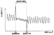
- the output voltage waveform of the acceleration sensor 11 during tire rotation is, for example, the waveform shown in FIG.
- the output voltage of the acceleration sensor 11 takes a maximum value at the start of grounding when the portion of the tread 31 corresponding to the location where the acceleration sensor 11 is disposed begins to ground as the tire 3 rotates.
- the section extraction unit 13a detects the start of grounding at which the output voltage of the acceleration sensor 11 takes a maximum value as the timing of the first peak value. Further, as shown in FIG.
- the voltage takes a local minimum.
- the section extraction unit 13a detects the end of grounding when the output voltage of the acceleration sensor 11 takes a minimum value as the timing of the second peak value.
- the reason why the output voltage of the acceleration sensor 11 takes a peak value at the above timing is as follows. That is, when the portion of the tread 31 corresponding to the location where the acceleration sensor 11 is disposed contacts with the rotation of the tire 3, the portion of the tire 3 that has been a substantially cylindrical surface is pressed in the vicinity of the acceleration sensor 11. To be flat. By receiving an impact at this time, the output voltage of the acceleration sensor 11 takes the first peak value. Further, when the portion of the tread 31 corresponding to the location where the acceleration sensor 11 is disposed moves away from the grounding surface as the tire 3 rotates, the tire 3 is released from pressing in the vicinity of the acceleration sensor 11 and is substantially flat from the plane. Return to the cylindrical shape.
- the output voltage of the acceleration sensor 11 takes the second peak value.
- the output voltage of the acceleration sensor 11 takes the first and second peak values at the start of grounding and at the end of grounding, respectively.
- the sign of the output voltage is also opposite.
- the section extraction unit 13a extracts the ground contact section of the acceleration sensor 11 by extracting the detection signal data including the timings of the first and second peak values, and the level calculation unit 13b indicates that it is in the ground contact section. To tell.
- the section extraction unit 13a sends a transmission trigger to the RF circuit 14 at this timing.
- road surface data such as ⁇ data generated by the level calculation unit 13b is transmitted from the RF circuit 14 as described later. In this way, data transmission by the RF circuit 14 is not always performed, but only when the acceleration sensor 11 is grounded, so that power consumption can be reduced.
- the level calculation unit 13b when notified from the section extraction unit 13a that it is in the grounding section, calculates the level of the high-frequency component caused by the vibration of the tire 3 included in the output voltage of the acceleration sensor 11 during that period. Then, the level calculation unit 13b transmits the calculation result to the data generation unit 13c as road surface data such as ⁇ data.
- the level of the high-frequency component is calculated as an index representing the road surface condition such as the road surface ⁇ .
- FIG. 6A shows a change in the output voltage of the acceleration sensor 11 when traveling on a high ⁇ road surface having a relatively large road surface ⁇ such as an asphalt road.
- FIG. 6B shows a change in the output voltage of the acceleration sensor 11 when the vehicle is traveling on a low ⁇ road surface where the road surface ⁇ is relatively small to the extent corresponding to the frozen road.
- the first and second peak values appear at the beginning and end of the contact section, that is, at the start and end of the contact of the acceleration sensor 11, regardless of the road surface ⁇ .
- the output voltage of the acceleration sensor 11 changes due to the influence of the road surface ⁇ .
- the road surface ⁇ is low, such as when traveling on a low ⁇ road surface
- fine high-frequency vibration due to slip of the tire 3 is superimposed on the output voltage.
- Such a fine high-frequency signal due to the slip of the tire 3 is not superposed when the road surface ⁇ is high, such as when traveling on a high ⁇ road surface.
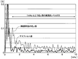
- the frequency analysis of the output voltage during the grounding section is performed for each of the cases where the road surface ⁇ is high and low, the result shown in FIG. 7 is obtained.
- the level is high when the road surface ⁇ is high or low, but in the high frequency range of 1 kHz or higher, the level is higher when the road surface ⁇ is low than when it is high. .
- the level of the high frequency component of the output voltage of the acceleration sensor 11 serves as an index representing the road surface state.
- the level calculation unit 13b calculates the level of the high frequency component of the output voltage of the acceleration sensor 11 during the grounding section by the level calculation unit 13b. Therefore, by calculating the level of the high frequency component of the output voltage of the acceleration sensor 11 during the grounding section by the level calculation unit 13b, this can be converted to ⁇ data. Further, from the ⁇ data, for example, when the road surface ⁇ is low, the road surface type corresponding to the road surface ⁇ can be detected as a road surface state, such as determining that the road is frozen.
- the level of the high frequency component can be calculated by extracting the high frequency component from the output voltage of the acceleration sensor 11 and integrating the extracted high frequency component during the grounding section.
- the high frequency components of the frequency bands fa to fb that are assumed to change according to the road surface condition and the road surface ⁇ are extracted by filtering or the like, and the voltages of the high frequency components of the frequency bands fa to fb extracted by the frequency analysis are obtained. Integrate.
- a capacitor (not shown) is charged. In this way, the amount of charge increases when the road surface ⁇ is high, such as when traveling on a high ⁇ road surface, compared to when the road surface ⁇ is low, such as when traveling on a low ⁇ road surface. .
- this charge amount as the ⁇ data, it is possible to estimate the road surface ⁇ such that the larger the charge amount indicated by the ⁇ data, the lower the road surface ⁇ .
- the data generation unit 13c basically generates road surface data based on the calculation result of the level calculation unit 13b.
- the data generation unit 13c adopts ⁇ data as it is as road surface data, obtains a road surface state such as a frozen road or an asphalt road from ⁇ data, and generates data indicating the road surface data as road surface data.
- the temperature of the traveling road surface is measured by the temperature sensor 12.
- the data generation unit 13c acquires the road surface temperature by inputting the detection signal of the temperature sensor 12, detects the type of the road surface from the acquired road surface temperature, or obtains from ⁇ data correction or ⁇ data. The type of road is corrected.
- the data generation unit 13c detects that the road surface is frozen as the type of road surface. Furthermore, the data generation unit 13c corrects the ⁇ data obtained from the high frequency component of the detection signal of the acceleration sensor 11 or the road surface type indicated by the ⁇ data when the road surface temperature detected by the temperature sensor 12 does not match. Or not adopted as a road surface condition detection result. For example, when the road surface type obtained from the high-frequency component of the detection signal of the acceleration sensor 11 is in a frozen state, and the road surface temperature detected by the temperature sensor 12 is 40 ° C., the road surface type of the frozen state is set. It is thought that there is an error in the detection result.
- the data generation unit 13c does not adopt the result transmitted from the level calculation unit 13b as the detection result of the road surface type.
- the road surface ⁇ indicated by the ⁇ data does not match the type of road surface obtained from the road surface temperature, for example, if the road surface ⁇ indicated by the ⁇ data is high even though the road surface temperature is detected as frozen, the ⁇ data Is corrected to a lower value than before the correction.
- the RF circuit 14 constitutes a transmission unit that transmits road surface data such as ⁇ data transmitted from the data generation unit 13 c to the receiver 21. Communication between the RF circuit 14 and the receiver 21 can be performed by a known short-range wireless communication technique such as Bluetooth (registered trademark).
- the timing for transmitting the road surface data is arbitrary, but as described above, in the present embodiment, the road surface data is transmitted from the RF circuit 14 by sending a transmission trigger from the section extracting unit 13a when the ground contact of the acceleration sensor 11 is completed. It is supposed to be. In this way, data transmission by the RF circuit 14 is not always performed, but only when the acceleration sensor 11 is grounded, so that power consumption can be reduced.
- the road surface data is sent together with the unique identification information (hereinafter referred to as ID information) of the wheels provided in advance for each tire 3 provided in the vehicle.
- ID information unique identification information
- the position of each wheel can be specified by a well-known wheel position detection device that detects which position of the vehicle the wheel is attached to. Therefore, by transmitting road surface data together with ID information to the receiver 21, data on which wheel is detected. Can be determined.
- the receiver 21 receives the road surface data transmitted from the tire mount sensor 1 and performs a process of outputting the road surface data to the vehicle communication device 24. Based on this, road surface data is sent from the vehicle communication device 24 to the communication center 200 collecting road information and the like.
- the receiver 21 performs processing for acquiring more accurate road surface data from the communication center 200 through the vehicle communication device 24. Further, the receiver 21 performs processing for obtaining road information scheduled to travel, for example, curve curvature information (hereinafter referred to as R information) from the navigation ECU 22 and obtaining vehicle speed information from the brake ECU 23. Then, the receiver 21 extracts road surface data of a road scheduled to travel from the road surface data acquired from the communication center 200, and based on the road surface data, road information obtained from the navigation ECU 22, and vehicle speed information obtained from the brake ECU 23, Determine the danger of the vehicle.
- R information curve curvature information
- the receiver 21 determines the risk of the vehicle based on the data on the location where the vehicle is scheduled to travel. Judgment. If the determination result indicates that the vehicle is dangerous, the receiver 21 performs various processes according to the risk of the vehicle.
- the receiver 21 determines that there is a risk of the vehicle, the receiver 21 transmits a control signal for informing the notification device 25 to that effect.
- the receiver 21 outputs a request signal for performing vehicle motion control for generating a braking force on the vehicle by transmitting a braking request to the brake ECU 23 as necessary.
- the receiver 21 stores R information corresponding to a change in the road surface ⁇ and a map or a function expression indicating the relationship between the vehicle speed and the danger of the vehicle.
- the receiver 21 stores the road surface data.
- the risk of the vehicle is determined based on a map or relational expression corresponding to the road surface ⁇ shown. For example, in the map or relational expression, the relationship between the radius of curvature of the curve of the road and the vehicle speed at which the curve can be curved is determined for each road surface ⁇ , and as the road surface ⁇ decreases, the curve of the same curvature radius is obtained.
- the vehicle speed that can be turned is also low.
- the receiver 21 determines whether or not a curve of a planned road can be bent when the vehicle continues to travel at the current vehicle speed. If there is no danger and the vehicle cannot turn, it is determined that there is a danger of the vehicle.
- the risk of the vehicle can be determined not only from the relationship between the curvature radius of the road curve and the vehicle speed but also from only the relationship between the road surface ⁇ and the vehicle speed. For example, since the braking distance becomes longer when the road surface ⁇ is low, it is determined that the vehicle is dangerous when the braking distance assumed from the road surface ⁇ and the vehicle speed is long. It can also be determined from information other than the radius of curvature and the vehicle speed.
- the navigation ECU 22 is provided in the navigation system and obtains information from a non-transitional physical storage medium such as a memory storing road information and measures the current position of the vehicle based on GPS (Global Positioning System) satellite position information. And so on. In other words, the navigation ECU 22 performs various processes relating to road guidance and the like.
- the vehicle danger avoidance device 100 of the present embodiment uses road information and current position information handled by the navigation ECU 22. Specifically, as described above, the road information is used to determine the danger of the vehicle and is transmitted from the navigation ECU 22 to the receiver 21.
- the current position information is transmitted from the navigation ECU 22 to the vehicle communication device 24, and when the road surface data is transmitted from the vehicle communication device 24 to the communication center 200, the current position information of the vehicle is attached together with the road surface data. Thereby, in the communication center 200, it can grasp
- navigation ECU22 was mentioned as an example as a road information acquisition part which acquires road information, and a position information acquisition part which acquires the information of present position here, things other than navigation ECU22 may be used.
- a portable device such as a cellular phone may be able to exchange information with each unit of the vehicle body side system 2 and the portable device may be used as a road information acquisition unit or a position information acquisition unit.
- the installation position of the communication system for performing communication with the communication center 200 installed in various places such as a road may be set as the current position of the vehicle.
- the brake ECU 23 constitutes a brake control device that performs various brake controls.
- the brake ECU 23 automatically generates brake fluid pressure by driving an actuator for brake fluid pressure control, and pressurizes a wheel cylinder to increase braking force. Can also be generated.
- the brake ECU 23 can also control the braking force of each wheel independently. Therefore, when a braking request is issued from the receiver 21 when it is determined that there is a risk of the vehicle, the braking force is generated for the vehicle by generating a desired braking force for the corresponding wheel. It is possible to make it.
- the brake ECU 23 performs vehicle speed calculation based on a detection signal of a wheel speed sensor (not shown), and transmits the calculation result to the receiver 21 as vehicle speed information.
- the brake ECU 23 is taken as an example of the vehicle speed acquisition unit, but the vehicle speed may be acquired from other than the brake ECU 23.
- the vehicle communication device 24 can perform road-to-vehicle communication, and exchanges information with the communication center 200 via a communication system (not shown) installed on a road, for example.
- the vehicle communication device 24 plays a role of transmitting road surface data transmitted from the receiver 21 to the communication center 200 or receiving more accurate road surface data from the communication center 200.
- the notification device 25 is composed of a meter display, for example, and is used to notify the driver that the vehicle is dangerous.
- the notification device 25 is configured by a meter display
- the notification device 25 is disposed at a place where the driver can visually recognize the vehicle while driving, for example, in an instrument panel in the vehicle.
- the control signal indicating that the vehicle is dangerous is transmitted from the receiver 21 to the meter indicator
- the meter display visually displays the risk to the driver by displaying in such a manner that the contents of the danger can be grasped. Can be notified.
- the notification device 25 can also be constituted by a buzzer or a voice guidance device. In that case, the notification device 25 can audibly notify the driver of the danger by a buzzer sound or voice guidance.
- the meter display device is exemplified as the notification device 25 that performs visual notification, the notification device 25 may be configured by a display device that displays information such as a head-up display.
- each part which comprises the vehicle body side system 2 is connected through in-vehicle LAN (abbreviation of Local * AreaNetwork) by CAN (abbreviation for Controller
- in-vehicle LAN abbreviation of Local * AreaNetwork
- CAN abbreviation for Controller
- the communication center 200 that exchanges information on road surface data with the vehicle danger avoidance device 100 performs a business of collecting road information and providing road information to vehicles and the like.
- the communication center 200 and the vehicle communication device 24 may be configured to directly communicate with each other, but the communication center 200 can communicate with the vehicle communication device 24 through a communication system installed in various places such as roads. Yes.
- the communication center 200 manages the road surface state information for each road location in the map data as a database, and maps the road surface state that changes every moment based on the received road surface data. Is going. That is, the communication center 200 updates the road surface state information for each road location in the map data based on the received road surface data.
- the communication center 200 provides road surface data to the vehicle from the database.
- the communication center 200 collects road surface data of the road on which the vehicle traveled from the vehicle travels, and updates the road surface data of each road in the map data based on the road surface data.
- the communication center 200 also collects weather information and the like, corrects each road surface data based on the weather information and updates it as more reliable road surface data.
- the communication center 200 acquires information on the amount of snow and the frozen road surface as weather information, and more accurate road surface data is sequentially stored by updating the snow covered road surface and the frozen road surface to the corresponding road surface data. I try to do it.
- the communication center 200 provides the vehicle with the road surface data stored in the database so that more accurate road surface data is transmitted to the vehicle.
- the communication center 200 collects road surface data from a large number of vehicles and updates the road surface data of each road in the map data stored in the database. As well as road surface data of a road to be traveled can be acquired.
- the control unit 13 extracts a high frequency component from the detection signal of the acceleration sensor 11, that is, the output voltage, and detects the road surface ⁇ based on the high frequency component extracted during the ground contact section. Or the type of road surface is detected. Then, ⁇ data indicating the road surface ⁇ or road surface data including the type of the road surface is created, and a frame storing the road surface data is transmitted to the receiver 21 through the RF circuit 14.
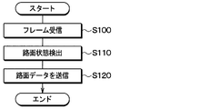
- the receiver 21 provided on the vehicle body performs the road surface data transfer process shown in FIG. Specifically, by receiving the frame in step S100, road surface data is received from the tire mount sensor 1, and in step S110, the road surface ⁇ and the road surface ⁇ are read by reading ⁇ data indicating the road surface ⁇ and information on the type of the road surface. Detects road surface conditions such as the type of road surface.
- step S120 the extracted data or the received road surface data is transmitted to the vehicle communication device 24 as it is or after being converted into a predetermined protocol. Thereby, road surface data indicating the road surface ⁇ detected by the vehicle, the type of road surface, and the like are transmitted to the communication center 200.
- the communication center 200 the road surface data of each road in the map data managed as a database is updated to the latest data in consideration of weather information and the like.
- the communication center 200 provides the vehicle with more accurate road surface data updated from the database.
- the receiver 21 also executes danger handling processing shown in FIG. 9 based on the road surface data.
- the risk of the vehicle is determined based on the road surface data. That is, since the road surface data sent from the communication center 200 includes data on the road on which the vehicle is scheduled to travel, the receiver 21 determines the risk of the vehicle based on the data on the location where the vehicle is scheduled to travel. Judgment. For example, as described above, the receiver 21 determines the risk of the vehicle based on a map or relational expression corresponding to the road surface ⁇ indicated by the road surface data.
- step S210 a control signal for instructing the notification device 25 that there is a risk of the vehicle is output.
- the receiver 21 outputs a request signal for performing vehicle motion control for generating a braking force on the vehicle by transmitting a braking request to the brake ECU 23 as necessary.
- a braking request can be issued according to the content of the danger, a braking force can be generated for all the wheels, or a specific wheel can be controlled to avoid spinning. Power can also be generated.
- the tire mount sensor 1 detects the road surface state such as the road surface ⁇ and the type of the road surface, and based on the road surface data indicating the detection result, The risk of the vehicle is judged. More specifically, the road surface data sent from the tire mount sensor 1 is transmitted to the communication center 200 to collect more accurate road surface data, and the vehicle receives more accurate road surface data from the communication center 200. The risk of the vehicle is determined based on the more accurate road surface data received.
- the road surface state can be detected without braking. Therefore, it becomes possible to detect the road surface condition at a higher frequency, so it is possible to detect the road surface condition in a wider range, and it is possible to more appropriately perform control for avoiding danger during traveling based on the road surface condition. It becomes.
- the receiver 21 determines the risk of the vehicle based on the road surface data transmitted from the communication center 200.
- the receiver 21 uses road surface data indicating the road surface state detected by the tire mount sensor 1 of the own vehicle instead of road surface data transmitted from the communication center 200 for determining the risk of the vehicle. Based on. Specifically, the road surface data sent from the tire mount sensor 1 is used when executing the process of determining the risk of the vehicle in step S200 in FIG.
- the risk of the vehicle can be determined based only on road surface data detected by the host vehicle.
- the receiver 21 sends road surface data indicating the road surface state detected by the tire mount sensor 1 to the communication center 200. For this reason, in the communication center 200, it is possible to perform mapping of the road surface data which changes every moment based on the road surface data sent from the vehicle.
- the first embodiment and the second embodiment described above are not unrelated to each other and can be combined.
- the risk of the vehicle is determined based on road surface data transmitted from the communication center 200 as in the first embodiment.
- the vehicle's communication is performed based on the road surface data sent from the tire mount sensor 1 of the own vehicle as in the second embodiment.
- Make a risk assessment In this way, when the communication between the vehicle communication device 24 and the communication center 200 can be performed, the risk of the vehicle can be determined based on more accurate road surface data, and even when communication cannot be performed, the vehicle is detected.
- the risk of the vehicle can be determined based on the road surface data.
- a ground contact area is identified from the detection signal of the acceleration sensor 11 which comprises a vibration detection part, and the road surface data by which the road surface state was shown by the calculation result of the level of the high frequency component in the detection signal in a ground contact area. It is used as.
- this is only an example of a method for detecting the road surface state using the detection signal at the vibration detection unit, and even if the road surface state is detected by another method using the detection signal at the vibration detection unit. good.
- control unit for instructing the danger notification.
- a control unit may be provided separately from the receiver 21, or other ECUs such as the navigation ECU 22 and the brake ECU 23 may function as the control unit.
Abstract
Provided is a vehicle risk avoidance device, wherein the condition of a road surface, such as road surface μ and road surface type, are detected by a tire mounted sensor (1), and the road surface data indicating the detection result is transmitted to a communication center (200). More accurate road surface data is then collected in the communication center (200) so that a vehicle receives even more accurate road surface data from the communication center (200). On the basis of the received more accurate road surface data, a determination regarding risk to the vehicle is made. By detecting the condition of a road surface using the tire mounted sensor (1) in this manner, it is possible to detect the road surface condition without applying the brakes. Consequently, the road surface condition can be more frequently detected, thereby enabling more extensive detection of the road surface condition, and more appropriate risk avoidance control based on the road surface condition during travel.
Description
本出願は、2016年2月19日に出願された日本特許出願番号2016-30254号に基づくもので、ここにその記載内容が参照により組み入れられる。
This application is based on Japanese Patent Application No. 2016-30254 filed on February 19, 2016, the description of which is incorporated herein by reference.
本開示は、車両の走行中に路面状態を検出し、路面状態に基づいて走行中の危険を回避するための制御、例えば危険性をドライバに報知したり、車両に対して制動力を発生させるなどの制御を行う車両用危険回避装置に関するものである。
The present disclosure detects a road surface condition while the vehicle is traveling, and performs control for avoiding danger during traveling based on the road surface condition, for example, notifies the driver of the danger or generates a braking force for the vehicle. The present invention relates to a vehicle danger avoidance device that performs control such as these.
従来、車両が走行している道路の滑りやすさを測定すると共に、その滑りやすさを車両通信装置を介して通信センターに送り、通信センターから他車両に伝えるようにした路面情報配信システムが開示されている(特許文献1参照)。具体的には、この路面情報配信システムでは、タイヤの回転速度を定期的に測定し、タイヤの回転速度に基づいて道路の滑りやすさを測定しており、その道路の滑りやすさのレベルを数値化して通信センターに送るようにしている。このような路面情報配信システムを用いることで、既に情報収集されている場所を車両が走行する際に、収集してある道路の滑りやすさのレベルを加味した車両運動制御が行え、車両のスリップやスピンなどをより的確に回避することが可能になる。
Conventionally, a road surface information distribution system has been disclosed that measures the slipperiness of a road on which a vehicle is traveling and sends the slipperiness to a communication center via a vehicle communication device and transmits the slipperiness to other vehicles from the communication center. (See Patent Document 1). Specifically, in this road surface information distribution system, the rotation speed of a tire is measured periodically, and the slipperiness of a road is measured based on the rotation speed of the tire, and the level of slipperiness of the road is measured. It is digitized and sent to the communication center. By using such a road surface information distribution system, when a vehicle travels in a place where information has already been collected, vehicle motion control can be performed taking into account the level of slipperiness of the collected road, and vehicle slip And spin can be avoided more accurately.
車両におけるタイヤの回転速度に基づいて道路の滑りやすさを検出するには、例えば制動によって車輪をスリップさせてタイヤの回転速度と車体速度とに差を発生させることが必要である。したがって、車両の走行中に高い頻度で道路の滑りやすさを検出することが難しく、走行中の道路の広い範囲に渡って滑りやすさを検出することができない。
In order to detect the slipperiness of the road based on the rotation speed of the tire in the vehicle, for example, it is necessary to slip the wheel by braking to generate a difference between the rotation speed of the tire and the vehicle body speed. Therefore, it is difficult to detect the slipperiness of the road at a high frequency while the vehicle is traveling, and it is not possible to detect the slipperiness over a wide range of the traveling road.
本開示は、より広い範囲で路面状態を検出でき、路面状態に基づく走行中の危険性回避のための制御をより適切に行うことができる車両用危険回避装置を提供することを目的とする。
This disclosure is intended to provide a vehicle risk avoidance device that can detect a road surface condition in a wider range and can more appropriately perform a control for avoiding a danger during traveling based on the road surface condition.
本開示の1つの観点における車両用危険回避装置は、車両に備えられるタイヤの裏面に取り付けられ、タイヤの振動の大きさに応じた検出信号を出力する振動検出部と、振動検出部の検出信号が示す振動データから路面状態を検出する信号処理部と、高周波成分のレベルの算出結果を路面状態が表された路面データとして送信する送信部と、を有するタイヤマウントセンサと、車体側に備えられ、送信部から送信された路面データを受信する受信機と、道路情報の収集を行う通信センターに対して路面データを伝えると共に通信センターから車両が走行予定の道路の路面状態を示す路面データを取得する車両通信装置と、道路情報を取得する道路情報取得部と、車両の現在位置を取得する位置情報取得部と、車両の速度である車速を取得する車速取得部と、を有する車体側システムと、を備えている。そして、車両側システムに、道路情報取得部が取得した道路情報と位置情報取得部が取得した現在位置と車速取得部が取得した車速および通信センターから取得した路面データに基づいて、車両の危険性を判定するとともに、車両の危険性があると判定すると車両を危険性から回避するための制御を行う制御部を備えている。
A vehicle danger avoidance device according to one aspect of the present disclosure is attached to a back surface of a tire provided in a vehicle and outputs a detection signal corresponding to the magnitude of vibration of the tire, and a detection signal of the vibration detection unit A tire mount sensor having a signal processing unit that detects a road surface state from vibration data indicated by the vehicle, and a transmission unit that transmits a calculation result of the level of a high-frequency component as road surface data representing the road surface state, and is provided on the vehicle body side. Communicating road surface data to a receiver that receives road surface data transmitted from the transmitter and a communication center that collects road information and obtaining road surface data indicating the road surface state of the road on which the vehicle is scheduled to travel A vehicle communication device, a road information acquisition unit that acquires road information, a position information acquisition unit that acquires the current position of the vehicle, and a vehicle speed that is a vehicle speed It comprises a body-side system comprising a vehicle speed acquiring unit, and the. Based on the road information acquired by the road information acquisition unit, the current position acquired by the position information acquisition unit, the vehicle speed acquired by the vehicle speed acquisition unit, and the road surface data acquired from the communication center, the vehicle side system And a control unit that performs control for avoiding the vehicle from danger when it is determined that there is a risk of the vehicle.
このように、タイヤマウントセンサで路面状態の検出を行い、その検出結果を示す路面データに基づいて、車両の危険性を判定するようにしている。より詳しくは、タイヤマウントセンサから送られてきた路面データを通信センターに伝えることでより正確な路面データを収集し、車両が通信センターからより正確な路面データを受け取るようにしている。そして、受け取ったより正確な路面データに基づいて、車両の危険性を判定している。
Thus, the road surface condition is detected by the tire mount sensor, and the risk of the vehicle is determined based on the road surface data indicating the detection result. More specifically, the road surface data sent from the tire mount sensor is transmitted to the communication center to collect more accurate road surface data, and the vehicle receives more accurate road surface data from the communication center. The risk of the vehicle is determined based on the more accurate road surface data received.
このように、タイヤマウントセンサを用いて路面状態の検出を行えば、制動を掛けることなく路面状態を検出できる。したがって、より高い頻度で路面状態の検出を行うことが可能となるため、より広範囲に路面状態を検出でき、路面状態に基づく走行中の危険性回避のための制御をより適切に行うことが可能となる。
Thus, if the road surface condition is detected using the tire mount sensor, the road surface condition can be detected without braking. Therefore, it becomes possible to detect the road surface condition at a higher frequency, so it is possible to detect the road surface condition in a wider range, and it is possible to more appropriately perform control for avoiding danger during traveling based on the road surface condition. It becomes.
以下、本開示の実施形態について図に基づいて説明する。なお、以下の各実施形態相互において、互いに同一もしくは均等である部分には、同一符号を付して説明を行う。
Hereinafter, embodiments of the present disclosure will be described with reference to the drawings. In the following embodiments, parts that are the same or equivalent to each other will be described with the same reference numerals.
(第1実施形態)
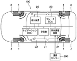
図1~図9を参照して、本実施形態にかかる車両用危険回避装置100について説明する。本実施形態にかかる車両用危険回避装置100は、車両の各車輪に備えられるタイヤの接地面に加わる振動に基づいて走行中の路面状態を推定し、この推定結果を通信センターに伝えたり、路面状態に基づいて車両の危険性の報知や車両運動制御を行うものである。 (First embodiment)
A vehicledanger avoidance device 100 according to this embodiment will be described with reference to FIGS. The vehicle danger avoidance device 100 according to the present embodiment estimates a road surface state during traveling based on vibration applied to a ground contact surface of a tire provided on each wheel of the vehicle, and transmits the estimation result to a communication center, Based on the state, the vehicle danger notification and vehicle motion control are performed.
図1~図9を参照して、本実施形態にかかる車両用危険回避装置100について説明する。本実施形態にかかる車両用危険回避装置100は、車両の各車輪に備えられるタイヤの接地面に加わる振動に基づいて走行中の路面状態を推定し、この推定結果を通信センターに伝えたり、路面状態に基づいて車両の危険性の報知や車両運動制御を行うものである。 (First embodiment)
A vehicle
図1および図2に示すように車両用危険回避装置100は、車輪側に設けられたタイヤマウントセンサ1と、車体側に備えられた各部を含む車体側システム2とを有する構成とされている。車体側システム2としては、受信機21、ナビゲーション制御用の電子制御装置(以下、ナビゲーションECUという)22、ブレーキ制御用の電子制御装置(以下、ブレーキECUという)23、車両通信装置24、報知装置25などが備えられている。
As shown in FIGS. 1 and 2, the vehicle danger avoidance device 100 includes a tire mount sensor 1 provided on the wheel side and a vehicle body side system 2 including each part provided on the vehicle body side. . The vehicle body side system 2 includes a receiver 21, an electronic control device for navigation control (hereinafter referred to as navigation ECU) 22, an electronic control device for brake control (hereinafter referred to as brake ECU) 23, a vehicle communication device 24, and a notification device. 25 etc. are provided.
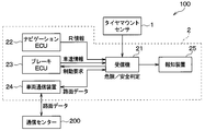
車両用危険回避装置100は、タイヤマウントセンサ1よりタイヤ3と走行中の路面との間の路面μを示すデータなどの走行中の路面状態を表すデータを送信する。以下、路面μのデータのことをμデータといい、路面状態を表すデータのことを路面データという。また、本実施形態の場合、車両用危険回避装置100は、図2に示すように、受信機21にてタイヤマウントセンサ1から送信された路面データを受信したのち、車両通信装置24を通じて路面データを通信センター200に送っている。逆に、車両用危険回避装置100は、車両通信装置24を通じて、通信センター200からより正確な路面データを取得している。さらに、車両用危険回避装置100は、受信機21で、通信センター200から取得したより正確な路面データおよびナビゲーションECU22やブレーキECU23から伝えられる各種情報に基づいて車両の危険性の判定を行っている。そして、車両の危険性があると判定されると、車両用危険回避装置100は、受信機21から報知装置25などにその旨を伝え、危険性の報知などを行う。具体的には、タイヤマウントセンサ1および受信機21は、以下のように構成されている。
The vehicle danger avoidance device 100 transmits data representing the road surface condition during traveling, such as data indicating the road surface μ between the tire 3 and the road surface during traveling, from the tire mount sensor 1. Hereinafter, the data on the road surface μ is referred to as μ data, and the data representing the road surface state is referred to as road surface data. In the case of the present embodiment, the vehicle danger avoidance device 100 receives the road surface data transmitted from the tire mount sensor 1 by the receiver 21 as shown in FIG. Is sent to the communication center 200. Conversely, the vehicle danger avoidance device 100 acquires more accurate road surface data from the communication center 200 through the vehicle communication device 24. Further, the vehicle danger avoidance device 100 uses the receiver 21 to determine the risk of the vehicle based on more accurate road surface data acquired from the communication center 200 and various information transmitted from the navigation ECU 22 and the brake ECU 23. . If it is determined that there is a risk of the vehicle, the vehicle danger avoidance device 100 notifies the notification device 25 and the like from the receiver 21 and notifies the danger. Specifically, the tire mount sensor 1 and the receiver 21 are configured as follows.
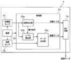
タイヤマウントセンサ1は、図3に示すように、加速度センサ11、温度センサ12、制御部13、RF回路14および電源15を備えた構成とされ、図4に示されるように、タイヤ3のトレッド31の裏面側に設けられる。
As shown in FIG. 3, the tire mount sensor 1 includes an acceleration sensor 11, a temperature sensor 12, a control unit 13, an RF circuit 14, and a power source 15. As shown in FIG. 31 is provided on the back side.
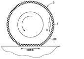
加速度センサ11は、タイヤに加わる振動を検出するための振動検出部を構成するものである。例えば、加速度センサ11は、タイヤ3が回転する際にタイヤマウントセンサ1が描く円軌道に対して接する方向、つまり図4中の矢印Xで示すタイヤ接線方向の振動に応じた検出信号として、加速度の検出信号を出力する。
The acceleration sensor 11 constitutes a vibration detection unit for detecting vibration applied to the tire. For example, the acceleration sensor 11 detects the acceleration as a detection signal corresponding to the vibration in the tire tangential direction indicated by the arrow X in FIG. 4 in the direction in contact with the circular orbit drawn by the tire mount sensor 1 when the tire 3 rotates. The detection signal is output.
温度センサ12は、温度に応じた検出信号を出力するもので、タイヤ3のうちのタイヤマウントセンサ1の取り付け位置の温度を検出することで、走行路面の温度を測定している。
The temperature sensor 12 outputs a detection signal corresponding to the temperature, and measures the temperature of the traveling road surface by detecting the temperature at the mounting position of the tire mount sensor 1 in the tire 3.
制御部13は、信号処理部に相当する部分であり、加速度センサ11の検出信号をタイヤ接線方向の振動データを表す検出信号として用いて、この検出信号を処理することで路面データを得て、それをRF回路14に伝える役割を果たす。具体的には、制御部13は、加速度センサ11の検出信号、つまり加速度センサ11の出力電圧の時間変化に基づいて、タイヤ3の回転時における加速度センサ11の接地区間を抽出している。なお、ここでいう接地区間とは、タイヤ3のトレッド31のうち加速度センサ11の配置箇所と対応する部分が路面接地している区間のことを意味している。本実施形態の場合、加速度センサ11の配置箇所がタイヤマウントセンサ1の配置箇所とされているため、接地区間とはタイヤ3のトレッド31のうちタイヤマウントセンサ1の配置箇所と対応する部分が路面接地している区間と同意である。
The control unit 13 is a portion corresponding to a signal processing unit, and uses the detection signal of the acceleration sensor 11 as a detection signal representing vibration data in the tire tangential direction, obtains road surface data by processing the detection signal, It plays a role of transmitting it to the RF circuit 14. Specifically, the control unit 13 extracts the ground contact section of the acceleration sensor 11 when the tire 3 rotates based on the detection signal of the acceleration sensor 11, that is, the time change of the output voltage of the acceleration sensor 11. Note that the contact section here means a section in which a portion of the tread 31 of the tire 3 corresponding to the position where the acceleration sensor 11 is disposed is grounded on the road surface. In the case of the present embodiment, since the location where the acceleration sensor 11 is disposed is the location where the tire mount sensor 1 is disposed, the portion corresponding to the location where the tire mount sensor 1 is disposed in the tread 31 of the tire 3 is the road surface. It is an agreement with the grounded section.
そして、接地区間中における加速度センサ11の検出信号に含まれる高周波成分が路面状態を表していることから、後述するように、制御部13は、検出信号から高周波成分を抽出すると共に抽出した高周波成分に基づいて路面μなどの路面状態を検出している。
Since the high frequency component included in the detection signal of the acceleration sensor 11 in the contact section represents the road surface state, the control unit 13 extracts the high frequency component from the detection signal and extracts the high frequency component as described later. Is used to detect the road surface condition such as the road surface μ.
また、本実施形態の場合は、温度センサ12によって走行路面の温度を測定していることから、制御部13は、走行路面の温度に基づいて、路面状態の検出を行ったり、加速度センサ11の検出信号の高周波成分から求めた路面状態の補正などを行っている。
In this embodiment, since the temperature of the traveling road surface is measured by the temperature sensor 12, the control unit 13 detects the road surface state based on the temperature of the traveling road surface, The road surface condition obtained from the high-frequency component of the detection signal is corrected.
このようにして、制御部13は、路面状態の検出を行うと、その路面状態を示した路面データを生成し、それをRF回路14に伝える処理を行う。これにより、RF回路14を通じて受信機21に路面データが伝えられるようになっている。
Thus, when the control unit 13 detects the road surface state, the control unit 13 generates road surface data indicating the road surface state, and performs a process of transmitting the road surface data to the RF circuit 14. Thereby, road surface data is transmitted to the receiver 21 through the RF circuit 14.
具体的には、制御部13は、CPU、ROM、RAM、I/Oなどを備えた周知のマイクロコンピュータによって構成され、ROMなどに記憶されたプログラムに従って上記した処理を行っている。そして、制御部13は、それらの処理を行う機能部として区間抽出部13a、レベル算出部13bおよびデータ生成部13cを備えている。
Specifically, the control unit 13 is configured by a known microcomputer including a CPU, ROM, RAM, I / O, and the like, and performs the above-described processing according to a program stored in the ROM. And the control part 13 is provided with the area extraction part 13a, the level calculation part 13b, and the data generation part 13c as a function part which performs those processes.
区間抽出部13aは、加速度センサ11の出力電圧で表される検出信号のピーク値を検出することで接地区間を抽出する。タイヤ回転時における加速度センサ11の出力電圧波形は例えば図5に示す波形となる。この図に示されるように、タイヤ3の回転に伴ってトレッド31のうち加速度センサ11の配置箇所と対応する部分が接地し始めた接地開始時に、加速度センサ11の出力電圧が極大値をとる。区間抽出部13aでは、この加速度センサ11の出力電圧が極大値をとる接地開始時を第1ピーク値のタイミングとして検出している。さらに、図5に示されるように、タイヤ3の回転に伴ってトレッド31のうち加速度センサ11の配置箇所と対応する部分が接地していた状態から接地しなくなる接地終了時に、加速度センサ11の出力電圧が極小値をとる。区間抽出部13aでは、この加速度センサ11の出力電圧が極小値をとる接地終了時を第2ピーク値のタイミングとして検出している。
The section extracting unit 13a extracts the ground section by detecting the peak value of the detection signal represented by the output voltage of the acceleration sensor 11. The output voltage waveform of the acceleration sensor 11 during tire rotation is, for example, the waveform shown in FIG. As shown in this figure, the output voltage of the acceleration sensor 11 takes a maximum value at the start of grounding when the portion of the tread 31 corresponding to the location where the acceleration sensor 11 is disposed begins to ground as the tire 3 rotates. The section extraction unit 13a detects the start of grounding at which the output voltage of the acceleration sensor 11 takes a maximum value as the timing of the first peak value. Further, as shown in FIG. 5, the output of the acceleration sensor 11 at the end of the grounding in which the portion corresponding to the location of the acceleration sensor 11 in the tread 31 is grounded as the tire 3 rotates, and the grounding is stopped. The voltage takes a local minimum. The section extraction unit 13a detects the end of grounding when the output voltage of the acceleration sensor 11 takes a minimum value as the timing of the second peak value.
加速度センサ11の出力電圧が上記のようなタイミングでピーク値をとるのは、以下の理由による。すなわち、タイヤ3の回転に伴ってトレッド31のうち加速度センサ11の配置箇所と対応する部分が接地する際、加速度センサ11の近傍においてタイヤ3のうちそれまで略円筒面であった部分が押圧されて平面状に変形する。このときの衝撃を受けることで、加速度センサ11の出力電圧が第1ピーク値をとる。また、タイヤ3の回転に伴ってトレッド31のうち加速度センサ11の配置箇所と対応する部分が接地面から離れる際には、加速度センサ11の近傍においてタイヤ3は押圧が解放されて平面状から略円筒状に戻る。このタイヤ3の形状が元に戻るときの衝撃を受けることで、加速度センサ11の出力電圧が第2ピーク値をとる。このようにして、加速度センサ11の出力電圧が接地開始時と接地終了時でそれぞれ第1、第2ピーク値をとるのである。また、タイヤ3が押圧される際の衝撃の方向と、押圧から開放される際の衝撃の方向は逆方向であるため、出力電圧の符号も逆方向となる。
The reason why the output voltage of the acceleration sensor 11 takes a peak value at the above timing is as follows. That is, when the portion of the tread 31 corresponding to the location where the acceleration sensor 11 is disposed contacts with the rotation of the tire 3, the portion of the tire 3 that has been a substantially cylindrical surface is pressed in the vicinity of the acceleration sensor 11. To be flat. By receiving an impact at this time, the output voltage of the acceleration sensor 11 takes the first peak value. Further, when the portion of the tread 31 corresponding to the location where the acceleration sensor 11 is disposed moves away from the grounding surface as the tire 3 rotates, the tire 3 is released from pressing in the vicinity of the acceleration sensor 11 and is substantially flat from the plane. Return to the cylindrical shape. By receiving an impact when the tire 3 returns to its original shape, the output voltage of the acceleration sensor 11 takes the second peak value. In this way, the output voltage of the acceleration sensor 11 takes the first and second peak values at the start of grounding and at the end of grounding, respectively. Moreover, since the direction of the impact when the tire 3 is pressed and the direction of the impact when released from the press are opposite directions, the sign of the output voltage is also opposite.
そして、区間抽出部13aは、第1、第2ピーク値のタイミングを含めた検出信号のデータを抽出することで加速度センサ11の接地区間を抽出し、接地区間中であることをレベル算出部13bに伝える。
Then, the section extraction unit 13a extracts the ground contact section of the acceleration sensor 11 by extracting the detection signal data including the timings of the first and second peak values, and the level calculation unit 13b indicates that it is in the ground contact section. To tell.
また、加速度センサ11の出力電圧が第2ピーク値をとるタイミングが加速度センサ11の接地終了時となるため、区間抽出部13aは、このタイミングでRF回路14に送信トリガを送っている。これにより、RF回路14より、後述するようにレベル算出部13bで作成されるμデータなどの路面データを送信させている。このように、RF回路14によるデータ送信を常に行うのではなく、加速度センサ11の接地終了時に限定して行うようにしているため、消費電力を低減することが可能となる。
Also, since the timing at which the output voltage of the acceleration sensor 11 takes the second peak value is when the grounding of the acceleration sensor 11 ends, the section extraction unit 13a sends a transmission trigger to the RF circuit 14 at this timing. As a result, road surface data such as μ data generated by the level calculation unit 13b is transmitted from the RF circuit 14 as described later. In this way, data transmission by the RF circuit 14 is not always performed, but only when the acceleration sensor 11 is grounded, so that power consumption can be reduced.
レベル算出部13bは、区間抽出部13aから接地区間中であることが伝えられると、その期間中に加速度センサ11の出力電圧に含まれるタイヤ3の振動に起因する高周波成分のレベルを算出する。そして、レベル算出部13bは、その算出結果をμデータなどの路面データとしてデータ生成部13cに伝える。ここで、路面μなどの路面状態を表わす指標として高周波成分のレベルを算出するようにしているが、その理由について図6A、図6Bおよび図7を参照して説明する。
The level calculation unit 13b, when notified from the section extraction unit 13a that it is in the grounding section, calculates the level of the high-frequency component caused by the vibration of the tire 3 included in the output voltage of the acceleration sensor 11 during that period. Then, the level calculation unit 13b transmits the calculation result to the data generation unit 13c as road surface data such as μ data. Here, the level of the high-frequency component is calculated as an index representing the road surface condition such as the road surface μ. The reason will be described with reference to FIGS. 6A, 6B, and 7. FIG.
図6Aは、アスファルト路のように路面μが比較的大きな高μ路面を走行している場合における加速度センサ11の出力電圧の変化を示している。また、図6Bは、凍結路の相当する程度に路面μが比較的小さな低μ路面を走行している場合における加速度センサ11の出力電圧の変化を示している。
FIG. 6A shows a change in the output voltage of the acceleration sensor 11 when traveling on a high μ road surface having a relatively large road surface μ such as an asphalt road. FIG. 6B shows a change in the output voltage of the acceleration sensor 11 when the vehicle is traveling on a low μ road surface where the road surface μ is relatively small to the extent corresponding to the frozen road.
これらの図から分かるように、路面μにかかわらず、接地区間の最初と最後、つまり加速度センサ11の接地開始時と接地終了時において第1、第2ピーク値が現れる。しかしながら、路面μの影響で、加速度センサ11の出力電圧が変化する。例えば、低μ路面の走行時のように路面μが低いときには、タイヤ3のスリップによる細かな高周波振動が出力電圧に重畳される。このようなタイヤ3のスリップによる細かな高周波信号は、高μ路面の走行時のように路面μが高い場合にはあまり重畳されない。
As can be seen from these figures, the first and second peak values appear at the beginning and end of the contact section, that is, at the start and end of the contact of the acceleration sensor 11, regardless of the road surface μ. However, the output voltage of the acceleration sensor 11 changes due to the influence of the road surface μ. For example, when the road surface μ is low, such as when traveling on a low μ road surface, fine high-frequency vibration due to slip of the tire 3 is superimposed on the output voltage. Such a fine high-frequency signal due to the slip of the tire 3 is not superposed when the road surface μ is high, such as when traveling on a high μ road surface.
このため、路面μが高い場合と低い場合それぞれについて、接地区間中における出力電圧の周波数解析を行うと、図7に示す結果となる。すなわち、低周波域では路面μが高い場合と低い場合のいずれを走行する場合にも高いレベルになるが、1kHz以上の高周波域では路面μが低い場合の方が高い場合よりも高いレベルになる。このため、加速度センサ11の出力電圧の高周波成分のレベルが路面状態を表す指標となる。
Therefore, when the frequency analysis of the output voltage during the grounding section is performed for each of the cases where the road surface μ is high and low, the result shown in FIG. 7 is obtained. In other words, in the low frequency range, the level is high when the road surface μ is high or low, but in the high frequency range of 1 kHz or higher, the level is higher when the road surface μ is low than when it is high. . For this reason, the level of the high frequency component of the output voltage of the acceleration sensor 11 serves as an index representing the road surface state.
したがって、レベル算出部13bによって接地区間中における加速度センサ11の出力電圧の高周波成分のレベルを算出することで、これをμデータとすることが可能となる。また、μデータから、例えば路面μが低い場合に凍結路と判定するなど、路面μと対応する路面の種類を路面状態として検出することもできる。
Therefore, by calculating the level of the high frequency component of the output voltage of the acceleration sensor 11 during the grounding section by the level calculation unit 13b, this can be converted to μ data. Further, from the μ data, for example, when the road surface μ is low, the road surface type corresponding to the road surface μ can be detected as a road surface state, such as determining that the road is frozen.
例えば、高周波成分のレベルは、加速度センサ11の出力電圧から高周波成分を抽出し、接地区間中に抽出した高周波成分を積分することで算出することができる。具体的には、路面状態や路面μに応じて変化すると想定される周波数帯域fa~fbの高周波成分をフィルタリングなどによって抽出し、周波数解析によって取り出した周波数帯域fa~fbの高周波数成分の電圧を積分する。例えば、図示しないコンデンサにチャージさせる。このようにすれば、高μ路面を走行している場合のように路面μが高い場合の方が低μ路面を走行している場合のように路面μが低い場合よりもチャージ量が多くなる。このチャージ量をμデータとして用いて、μデータが示すチャージ量が多いほど路面μが低いというように路面μを推定できる。
For example, the level of the high frequency component can be calculated by extracting the high frequency component from the output voltage of the acceleration sensor 11 and integrating the extracted high frequency component during the grounding section. Specifically, the high frequency components of the frequency bands fa to fb that are assumed to change according to the road surface condition and the road surface μ are extracted by filtering or the like, and the voltages of the high frequency components of the frequency bands fa to fb extracted by the frequency analysis are obtained. Integrate. For example, a capacitor (not shown) is charged. In this way, the amount of charge increases when the road surface μ is high, such as when traveling on a high μ road surface, compared to when the road surface μ is low, such as when traveling on a low μ road surface. . Using this charge amount as the μ data, it is possible to estimate the road surface μ such that the larger the charge amount indicated by the μ data, the lower the road surface μ.
データ生成部13cは、基本的には、レベル算出部13bでの算出結果に基づいて路面データを生成している。例えば、データ生成部13cは、μデータをそのまま路面データとして採用したり、μデータから凍結路やアスファルト路のような路面状態を求めて、それを示すデータを路面データとして生成している。
The data generation unit 13c basically generates road surface data based on the calculation result of the level calculation unit 13b. For example, the data generation unit 13c adopts μ data as it is as road surface data, obtains a road surface state such as a frozen road or an asphalt road from μ data, and generates data indicating the road surface data as road surface data.
また、上記したように、本実施形態の場合は、温度センサ12によって走行路面の温度を測定している。これに基づき、データ生成部13cは、温度センサ12の検出信号を入力することで路面温度を取得し、取得した路面温度から路面の種類を検出したり、μデータの補正もしくはμデータから得た路面の種類の補正を行っている。
Further, as described above, in the present embodiment, the temperature of the traveling road surface is measured by the temperature sensor 12. Based on this, the data generation unit 13c acquires the road surface temperature by inputting the detection signal of the temperature sensor 12, detects the type of the road surface from the acquired road surface temperature, or obtains from μ data correction or μ data. The type of road is corrected.
例えば、温度センサ12で検出された路面温度がマイナスであった場合には、データ生成部13cは、路面の種類として路面が凍結状態であることを検出している。さらに、データ生成部13cは、加速度センサ11の検出信号の高周波成分から求めたμデータもしくはμデータが示す路面の種類が温度センサ12で検出された路面温度と合致しない場合には、それを補正したり、路面状態の検出結果として採用しないようにする。例えば、加速度センサ11の検出信号の高周波成分から求めた路面の種類が凍結状態であった場合において、温度センサ12で検出された路面温度が40℃であったときには、凍結状態という路面の種類の検出結果に誤りがあると考えられる。この場合には、データ生成部13cは、レベル算出部13bから伝えられる結果を路面の種類の検出結果としては採用しないようにする。同様に、μデータが示す路面μが路面温度から得た路面の種類と合致しない場合、例えば路面温度から凍結状態と検出されているのにμデータが示す路面μが高い場合には、μデータが示す路面μを補正して補正前よりも低い値にしたりする。
For example, when the road surface temperature detected by the temperature sensor 12 is negative, the data generation unit 13c detects that the road surface is frozen as the type of road surface. Furthermore, the data generation unit 13c corrects the μ data obtained from the high frequency component of the detection signal of the acceleration sensor 11 or the road surface type indicated by the μ data when the road surface temperature detected by the temperature sensor 12 does not match. Or not adopted as a road surface condition detection result. For example, when the road surface type obtained from the high-frequency component of the detection signal of the acceleration sensor 11 is in a frozen state, and the road surface temperature detected by the temperature sensor 12 is 40 ° C., the road surface type of the frozen state is set. It is thought that there is an error in the detection result. In this case, the data generation unit 13c does not adopt the result transmitted from the level calculation unit 13b as the detection result of the road surface type. Similarly, if the road surface μ indicated by the μ data does not match the type of road surface obtained from the road surface temperature, for example, if the road surface μ indicated by the μ data is high even though the road surface temperature is detected as frozen, the μ data Is corrected to a lower value than before the correction.
RF回路14は、データ生成部13cから伝えられたμデータなどの路面データを受信機21に対して送信する送信部を構成するものである。RF回路14と受信機21との間の通信は、例えば、Bluetooth(登録商標)などの公知の近距離無線通信技術によって実施可能である。路面データを送信するタイミングについては任意であるが、上記したように、本実施形態では、加速度センサ11の接地終了時に区間抽出部13aから送信トリガが送られることでRF回路14から路面データが送られるようになっている。このように、RF回路14によるデータ送信を常に行うのではなく、加速度センサ11の接地終了時に限定して行うようにしているため、消費電力を低減することが可能となる。
The RF circuit 14 constitutes a transmission unit that transmits road surface data such as μ data transmitted from the data generation unit 13 c to the receiver 21. Communication between the RF circuit 14 and the receiver 21 can be performed by a known short-range wireless communication technique such as Bluetooth (registered trademark). The timing for transmitting the road surface data is arbitrary, but as described above, in the present embodiment, the road surface data is transmitted from the RF circuit 14 by sending a transmission trigger from the section extracting unit 13a when the ground contact of the acceleration sensor 11 is completed. It is supposed to be. In this way, data transmission by the RF circuit 14 is not always performed, but only when the acceleration sensor 11 is grounded, so that power consumption can be reduced.
また、路面データについては、車両に備えられたタイヤ3毎に予め備えられている車輪の固有識別情報(以下、ID情報という)と共に送られる。各車輪の位置については、車輪が車両のどの位置に取り付けられているかを検出する周知の車輪位置検出装置によって特定できることから、受信機21にID情報と共に路面データを伝えることで、どの車輪のデータであるかが判別可能になる。
Further, the road surface data is sent together with the unique identification information (hereinafter referred to as ID information) of the wheels provided in advance for each tire 3 provided in the vehicle. The position of each wheel can be specified by a well-known wheel position detection device that detects which position of the vehicle the wheel is attached to. Therefore, by transmitting road surface data together with ID information to the receiver 21, data on which wheel is detected. Can be determined.
一方、受信機21は、タイヤマウントセンサ1より送信された路面データを受信し、路面データを車両通信装置24に出力する処理を行う。これに基づき、車両通信装置24から道路情報などを収集している通信センター200に路面データが送られるようになっている。
On the other hand, the receiver 21 receives the road surface data transmitted from the tire mount sensor 1 and performs a process of outputting the road surface data to the vehicle communication device 24. Based on this, road surface data is sent from the vehicle communication device 24 to the communication center 200 collecting road information and the like.
また、受信機21は、車両通信装置24を通じて通信センター200からより正確な路面データを取得する処理を行っている。さらに、受信機21は、ナビゲーションECU22から走行予定の道路情報、例えばカーブの曲率情報(以下、R情報という)を取得したり、ブレーキECU23から車速情報を取得する処理も行っている。そして、受信機21は、通信センター200から取得した路面データから走行予定の道路の路面データを抽出し、その路面データとナビゲーションECU22から得られる道路情報およびブレーキECU23から得られる車速情報に基づいて、車両の危険性を判定する。すなわち、通信センター200から送られてくる路面データには車両が走行予定の道路のデータも含まれていることから、受信機21は、その走行予定の場所のデータに基づいて車両の危険性を判定している。この判定結果が車両に危険性があるというものであれば、受信機21は、車両の危険性に応じた各種処理を行う。
In addition, the receiver 21 performs processing for acquiring more accurate road surface data from the communication center 200 through the vehicle communication device 24. Further, the receiver 21 performs processing for obtaining road information scheduled to travel, for example, curve curvature information (hereinafter referred to as R information) from the navigation ECU 22 and obtaining vehicle speed information from the brake ECU 23. Then, the receiver 21 extracts road surface data of a road scheduled to travel from the road surface data acquired from the communication center 200, and based on the road surface data, road information obtained from the navigation ECU 22, and vehicle speed information obtained from the brake ECU 23, Determine the danger of the vehicle. That is, since the road surface data sent from the communication center 200 includes data on the road on which the vehicle is scheduled to travel, the receiver 21 determines the risk of the vehicle based on the data on the location where the vehicle is scheduled to travel. Judgment. If the determination result indicates that the vehicle is dangerous, the receiver 21 performs various processes according to the risk of the vehicle.
例えば、受信機21は、車両の危険性があると判定すると、報知装置25にその旨の報知を行わせる制御信号を伝える。また、受信機21は、必要に応じて、ブレーキECU23に制動要求を伝えることで車両に対して制動力を発生させるという車両運動制御を行うための要求信号を出力する。
For example, when the receiver 21 determines that there is a risk of the vehicle, the receiver 21 transmits a control signal for informing the notification device 25 to that effect. In addition, the receiver 21 outputs a request signal for performing vehicle motion control for generating a braking force on the vehicle by transmitting a braking request to the brake ECU 23 as necessary.
具体的には、受信機21には、路面μの変化に対応したR情報および車速と車両の危険性との関係を示すマップもしくは関数式が記憶されており、受信機21は、路面データが示す路面μと対応するマップもしくは関係式に基づいて車両の危険性を判定する。例えば、マップもしくは関係式は、道路のカーブの曲率半径とそのカーブを曲がることができる車速との関係が路面μ毎に決まっており、路面μが低くなる程、同じ曲率半径のカーブであっても曲がることのできる車速が低くなっている。このようなマップもしくは関係式を用いて、受信機21は、現在の車速で走行を続けた場合に、走行予定の道路のカーブを曲がれるか否かを判定しており、曲がれるのであれば車両の危険性はなく、曲がれないのであれば車両の危険性があると判定している。
Specifically, the receiver 21 stores R information corresponding to a change in the road surface μ and a map or a function expression indicating the relationship between the vehicle speed and the danger of the vehicle. The receiver 21 stores the road surface data. The risk of the vehicle is determined based on a map or relational expression corresponding to the road surface μ shown. For example, in the map or relational expression, the relationship between the radius of curvature of the curve of the road and the vehicle speed at which the curve can be curved is determined for each road surface μ, and as the road surface μ decreases, the curve of the same curvature radius is obtained. The vehicle speed that can be turned is also low. Using such a map or a relational expression, the receiver 21 determines whether or not a curve of a planned road can be bent when the vehicle continues to travel at the current vehicle speed. If there is no danger and the vehicle cannot turn, it is determined that there is a danger of the vehicle.
また、ここでは車両の危険性の判定として、路面μと対応したマップもしくは関係式を用いて行う場合を説明したが、路面の種類と対応したマップもしくは関係式を用いることもできる。また、道路のカーブの曲率半径と車速との関係だけでなく、単に路面μと車速との関係のみから車両の危険性を判定することもできる。例えば、路面μが低いと制動距離が長くなることから、路面μと車速から想定される制動距離が長い場合に車両に危険性があると判定するなど、車両の危険性については、道路のカーブの曲率半径および車速以外の情報から判定することもできる。
In addition, here, a case has been described in which a map or relational expression corresponding to the road surface μ is used as the determination of the risk of the vehicle, but a map or relational expression corresponding to the type of road surface can also be used. Further, the risk of the vehicle can be determined not only from the relationship between the curvature radius of the road curve and the vehicle speed but also from only the relationship between the road surface μ and the vehicle speed. For example, since the braking distance becomes longer when the road surface μ is low, it is determined that the vehicle is dangerous when the braking distance assumed from the road surface μ and the vehicle speed is long. It can also be determined from information other than the radius of curvature and the vehicle speed.
ナビゲーションECU22は、ナビゲーションシステムに備えられ、道路情報などを記憶したメモリなどの非遷移的実体的記憶媒体からの情報取得やGPS(Global PositioningSystemの略)衛星の位置情報に基づく車両の現在位置の計測などを行う。換言すれば、ナビゲーションECU22は、道路案内等に関する各種処理を行う。本実施形態の車両用危険回避装置100は、ナビゲーションECU22が取り扱っている道路情報や現在位置情報を使用している。具体的には、上記したように、道路情報については車両の危険性の判定に用いられ、ナビゲーションECU22から受信機21に伝えられる。また、現在位置情報については、ナビゲーションECU22から車両通信装置24に伝えられ、車両通信装置24から通信センター200に路面データを送る際に、路面データと共に車両の現在位置情報を付けて送られる。これにより、通信センター200において、路面データが示す路面μもしくは路面の種類がどの場所のものなのかが把握できるようになっている。
The navigation ECU 22 is provided in the navigation system and obtains information from a non-transitional physical storage medium such as a memory storing road information and measures the current position of the vehicle based on GPS (Global Positioning System) satellite position information. And so on. In other words, the navigation ECU 22 performs various processes relating to road guidance and the like. The vehicle danger avoidance device 100 of the present embodiment uses road information and current position information handled by the navigation ECU 22. Specifically, as described above, the road information is used to determine the danger of the vehicle and is transmitted from the navigation ECU 22 to the receiver 21. Further, the current position information is transmitted from the navigation ECU 22 to the vehicle communication device 24, and when the road surface data is transmitted from the vehicle communication device 24 to the communication center 200, the current position information of the vehicle is attached together with the road surface data. Thereby, in the communication center 200, it can grasp | ascertain which place the road surface micro which road surface data shows, or the kind of road surface is.
なお、ここでは道路情報の取得を行う道路情報取得部や現在位置の情報の取得を行う位置情報取得部としてナビゲーションECU22を例に挙げて説明したが、ナビゲーションECU22以外のものを用いても良い。例えば、携帯電話などの携帯機器を車体側システム2の各部と情報交換できるようにし、携帯機器を道路情報取得部や位置情報取得部として用いても良い。また、道路などの各所に設置された通信センター200との通信を行うための通信システムの設置位置を車両の現在位置としても良い。
In addition, although navigation ECU22 was mentioned as an example as a road information acquisition part which acquires road information, and a position information acquisition part which acquires the information of present position here, things other than navigation ECU22 may be used. For example, a portable device such as a cellular phone may be able to exchange information with each unit of the vehicle body side system 2 and the portable device may be used as a road information acquisition unit or a position information acquisition unit. Further, the installation position of the communication system for performing communication with the communication center 200 installed in various places such as a road may be set as the current position of the vehicle.
ブレーキECU23は、様々なブレーキ制御を行う制動制御装置を構成するものであり、ブレーキ液圧制御用のアクチュエータを駆動することで自動的にブレーキ液圧を発生させ、ホイールシリンダを加圧して制動力を発生させることもできる。また、ブレーキECU23は、各車輪の制動力を独立して制御することもできる。したがって、受信機21より、車両の危険性があると判定されたときに制動要求が出されると、それに応じた車輪に対して所望の制動力を発生させることで車両に対して制動力を発生させることが可能となっている。また、ブレーキECU23では、図示しない車輪速度センサの検出信号などに基づいて車速演算などを行っており、その演算結果を車速情報として受信機21に伝えている。なお、ここでは車速取得部としてブレーキECU23を例に挙げているが、ブレーキECU23以外から車速を取得してもよい。
The brake ECU 23 constitutes a brake control device that performs various brake controls. The brake ECU 23 automatically generates brake fluid pressure by driving an actuator for brake fluid pressure control, and pressurizes a wheel cylinder to increase braking force. Can also be generated. The brake ECU 23 can also control the braking force of each wheel independently. Therefore, when a braking request is issued from the receiver 21 when it is determined that there is a risk of the vehicle, the braking force is generated for the vehicle by generating a desired braking force for the corresponding wheel. It is possible to make it. In addition, the brake ECU 23 performs vehicle speed calculation based on a detection signal of a wheel speed sensor (not shown), and transmits the calculation result to the receiver 21 as vehicle speed information. Here, the brake ECU 23 is taken as an example of the vehicle speed acquisition unit, but the vehicle speed may be acquired from other than the brake ECU 23.
車両通信装置24は、路車間通信を行うことができるものであり、例えば道路などに設置されている図示しない通信システムを介して、通信センター200との情報交換を行う。本実施形態の場合、車両通信装置24は、受信機21から伝えられた路面データを通信センター200に送信したり、通信センター200からより正確な路面データを受信する役割を果たしている。
The vehicle communication device 24 can perform road-to-vehicle communication, and exchanges information with the communication center 200 via a communication system (not shown) installed on a road, for example. In the case of this embodiment, the vehicle communication device 24 plays a role of transmitting road surface data transmitted from the receiver 21 to the communication center 200 or receiving more accurate road surface data from the communication center 200.
報知装置25は、例えばメータ表示器などで構成され、ドライバに対して車両に危険性があることの報知に用いられる。報知装置25をメータ表示器で構成する場合、ドライバが車両の運転中に視認可能な場所に配置され、例えば車両におけるインストルメントパネル内に設置される。メータ表示器は、受信機21から車両に危険性がある旨の制御信号が伝えられると、その危険性の内容が把握できる態様で表示を行うことで、視覚的にドライバに対して危険性を報知することができる。
The notification device 25 is composed of a meter display, for example, and is used to notify the driver that the vehicle is dangerous. When the notification device 25 is configured by a meter display, the notification device 25 is disposed at a place where the driver can visually recognize the vehicle while driving, for example, in an instrument panel in the vehicle. When the control signal indicating that the vehicle is dangerous is transmitted from the receiver 21 to the meter indicator, the meter display visually displays the risk to the driver by displaying in such a manner that the contents of the danger can be grasped. Can be notified.
なお、報知装置25をブザーや音声案内装置などで構成することもできる。その場合、報知装置25は、ブザー音や音声案内によって、聴覚的にドライバに対して危険性を報知することができる。また、視覚的な報知を行う報知装置25としてメータ表示器を例に挙げたが、ヘッドアップディスプレイなどの情報表示を行う表示器によって報知装置25を構成しても良い。
Note that the notification device 25 can also be constituted by a buzzer or a voice guidance device. In that case, the notification device 25 can audibly notify the driver of the danger by a buzzer sound or voice guidance. In addition, although the meter display device is exemplified as the notification device 25 that performs visual notification, the notification device 25 may be configured by a display device that displays information such as a head-up display.
以上のようにして、本実施形態にかかる車両用危険回避装置100が構成されている。なお、車体側システム2を構成する各部が例えばCAN(Controller AreaNetworkの略)通信などによる車内LAN(Local AreaNetworkの略)を通じて接続されている。このため、車内LANを通じて各部が互いに情報伝達できるようになっている。
As described above, the vehicle danger avoidance device 100 according to the present embodiment is configured. In addition, each part which comprises the vehicle body side system 2 is connected through in-vehicle LAN (abbreviation of Local * AreaNetwork) by CAN (abbreviation for Controller | AreaNetwork) etc., for example. For this reason, each part can communicate with each other through the in-vehicle LAN.
一方、車両用危険回避装置100と路面データに関する情報交換を行う通信センター200は、道路情報の収集を行うと共に道路情報を車両などに提供する事業を行っている。通信センター200と車両通信装置24とが直接通信を行える形態とされていても良いが、通信センター200は道路などの各所に設置された通信システムを通じて車両通信装置24との通信が可能となっている。
On the other hand, the communication center 200 that exchanges information on road surface data with the vehicle danger avoidance device 100 performs a business of collecting road information and providing road information to vehicles and the like. The communication center 200 and the vehicle communication device 24 may be configured to directly communicate with each other, but the communication center 200 can communicate with the vehicle communication device 24 through a communication system installed in various places such as roads. Yes.
本実施形態の場合、通信センター200は、地図データ中の各道路の場所ごとの路面状態の情報をデータベースとして管理しており、受信した路面データに基づいて時々刻々と変化する路面状態のマッピングを行っている。つまり、通信センター200は、受信した路面データに基づいて地図データ中の各道路の場所ごとの路面状態の情報を更新している。そして、通信センター200は、そのデータベースから車両に対して路面データを提供している。
In the case of this embodiment, the communication center 200 manages the road surface state information for each road location in the map data as a database, and maps the road surface state that changes every moment based on the received road surface data. Is going. That is, the communication center 200 updates the road surface state information for each road location in the map data based on the received road surface data. The communication center 200 provides road surface data to the vehicle from the database.
具体的には、通信センター200は、車両から送られてくる車両が走行した道路の路面データを収集し、その路面データに基づいて地図データ中の各道路の路面データを更新している。また、通信センター200は、天気情報等も収集しており、天気情報等に基づいて各路面データを補正し、より確かな路面データとして更新している。例えば、通信センター200は、天気情報として積雪量や凍結路面に関する情報を取得しており、積雪路面や凍結路面については、それに対応する路面データに更新することでより正確な路面データが逐次記憶されるようにしている。そして、通信センター200は、データベースに記憶してある路面データを車両に提供することで、より正確な路面データを車両に伝えるようにしている。このとき、通信センター200では、多数の車両から路面データを収集してデータベースに記憶している地図データ中の各道路の路面データを更新していることから、各車両は、現在位置の路面データだけでなく、走行予定の道路の路面データについても取得できる。
Specifically, the communication center 200 collects road surface data of the road on which the vehicle traveled from the vehicle travels, and updates the road surface data of each road in the map data based on the road surface data. The communication center 200 also collects weather information and the like, corrects each road surface data based on the weather information and updates it as more reliable road surface data. For example, the communication center 200 acquires information on the amount of snow and the frozen road surface as weather information, and more accurate road surface data is sequentially stored by updating the snow covered road surface and the frozen road surface to the corresponding road surface data. I try to do it. The communication center 200 provides the vehicle with the road surface data stored in the database so that more accurate road surface data is transmitted to the vehicle. At this time, the communication center 200 collects road surface data from a large number of vehicles and updates the road surface data of each road in the map data stored in the database. As well as road surface data of a road to be traveled can be acquired.
続いて、本実施形態にかかる車両用危険回避装置100の作動について、図8、図9に示すフローチャートを参照して説明する。
Next, the operation of the vehicle danger avoidance device 100 according to this embodiment will be described with reference to the flowcharts shown in FIGS.
まず、各車輪のタイヤマウントセンサ1では、制御部13にて、加速度センサ11の検出信号、つまり出力電圧から高周波成分が抽出され、接地区間中に抽出した高周波成分に基づいて路面μの検出が行われたり、路面の種類の検出が行われる。そして、路面μを示すμデータもしくは路面の種類を含む路面データが作成され、その路面データが格納されたフレームがRF回路14を通じて受信機21に向けて送信される。
First, in the tire mount sensor 1 of each wheel, the control unit 13 extracts a high frequency component from the detection signal of the acceleration sensor 11, that is, the output voltage, and detects the road surface μ based on the high frequency component extracted during the ground contact section. Or the type of road surface is detected. Then, μ data indicating the road surface μ or road surface data including the type of the road surface is created, and a frame storing the road surface data is transmitted to the receiver 21 through the RF circuit 14.
これに基づいて、車体側に備えられた受信機21では、図8に示す路面データの授受処理を行う。具体的には、ステップS100においてフレーム受信を行うことで、タイヤマウントセンサ1から路面データを受け取り、ステップS110において路面データから路面μを示すμデータや路面の種類に関する情報を読み取ることで路面μや路面の種類などの路面状態を検出する。そして、ステップS120において、抽出したデータもしくは受信した路面データをそのまま、もしくは所定のプロトコルに変換して車両通信装置24に伝える。これにより、車両で検出した路面μや路面の種類などを示す路面データが通信センター200に伝えられる。これにより、通信センター200では、天気情報等も加味されて、データベースとして管理している地図データ中の各道路の路面データが最新のデータに更新される。そして、通信センター200からは、データベースから更新後のより正確な路面データが車両に提供される。
Based on this, the receiver 21 provided on the vehicle body performs the road surface data transfer process shown in FIG. Specifically, by receiving the frame in step S100, road surface data is received from the tire mount sensor 1, and in step S110, the road surface μ and the road surface μ are read by reading μ data indicating the road surface μ and information on the type of the road surface. Detects road surface conditions such as the type of road surface. In step S120, the extracted data or the received road surface data is transmitted to the vehicle communication device 24 as it is or after being converted into a predetermined protocol. Thereby, road surface data indicating the road surface μ detected by the vehicle, the type of road surface, and the like are transmitted to the communication center 200. Thereby, in the communication center 200, the road surface data of each road in the map data managed as a database is updated to the latest data in consideration of weather information and the like. The communication center 200 provides the vehicle with more accurate road surface data updated from the database.
また、受信機21では、路面データに基づいて、図9に示す危険対応処理も実行している。まず、ステップS200において、路面データに基づいて車両の危険性を判定する。すなわち、通信センター200から送られてくる路面データには車両が走行予定の道路のデータも含まれていることから、受信機21は、その走行予定の場所のデータに基づいて車両の危険性を判定している。例えば、上記したように、受信機21は、路面データが示す路面μと対応するマップもしくは関係式に基づいて車両の危険性を判定する。ここで、車両の危険性があることが判定されると、ステップS210に進んで報知装置25に対して車両の危険性があることの報知を指示する制御信号を出力する。また、受信機21は、必要に応じて、ブレーキECU23に制動要求を伝えることで車両に対して制動力を発生させるという車両運動制御を行うための要求信号を出力する。このとき、危険性の内容に応じて制動要求を出すことができ、全車輪に対して制動力を発生させることもできるし、車両がスピンすることを回避するために特定の車輪に対して制動力を発生させることもできる。
In addition, the receiver 21 also executes danger handling processing shown in FIG. 9 based on the road surface data. First, in step S200, the risk of the vehicle is determined based on the road surface data. That is, since the road surface data sent from the communication center 200 includes data on the road on which the vehicle is scheduled to travel, the receiver 21 determines the risk of the vehicle based on the data on the location where the vehicle is scheduled to travel. Judgment. For example, as described above, the receiver 21 determines the risk of the vehicle based on a map or relational expression corresponding to the road surface μ indicated by the road surface data. If it is determined that there is a risk of the vehicle, the process proceeds to step S210, and a control signal for instructing the notification device 25 that there is a risk of the vehicle is output. In addition, the receiver 21 outputs a request signal for performing vehicle motion control for generating a braking force on the vehicle by transmitting a braking request to the brake ECU 23 as necessary. At this time, a braking request can be issued according to the content of the danger, a braking force can be generated for all the wheels, or a specific wheel can be controlled to avoid spinning. Power can also be generated.
これにより、ドライバは報知装置25による危険性の報知に基づいて、車両を減速するなどの適切な対応をとることが可能になる。また、必要に応じて、車両の危険性を回避するための車両運動制御を実行することで、ドライバが車両の危険性に対して瞬時に対応できなかったとしても、車両の危険性を回避することが可能となる。
This allows the driver to take appropriate measures such as decelerating the vehicle based on the danger notification by the notification device 25. In addition, if necessary, the vehicle motion control for avoiding the danger of the vehicle is executed, so that the danger of the vehicle is avoided even if the driver cannot respond to the danger of the vehicle instantly. It becomes possible.
以上説明したように、本実施形態にかかる車両用危険回避装置100では、タイヤマウントセンサ1で路面μや路面の種類などの路面状態の検出を行い、その検出結果を示す路面データに基づいて、車両の危険性を判定するようにしている。より詳しくは、タイヤマウントセンサ1から送られてきた路面データを通信センター200に伝えることでより正確な路面データを収集し、車両が通信センター200からより正確な路面データを受け取るようにしている。そして、受け取ったより正確な路面データに基づいて、車両の危険性を判定している。
As described above, in the vehicle danger avoidance device 100 according to the present embodiment, the tire mount sensor 1 detects the road surface state such as the road surface μ and the type of the road surface, and based on the road surface data indicating the detection result, The risk of the vehicle is judged. More specifically, the road surface data sent from the tire mount sensor 1 is transmitted to the communication center 200 to collect more accurate road surface data, and the vehicle receives more accurate road surface data from the communication center 200. The risk of the vehicle is determined based on the more accurate road surface data received.
このように、タイヤマウントセンサ1を用いて路面状態の検出を行えば、制動を掛けることなく路面状態を検出できる。したがって、より高い頻度で路面状態の検出を行うことが可能となるため、より広範囲に路面状態を検出でき、路面状態に基づく走行中の危険性回避のための制御をより適切に行うことが可能となる。
Thus, if the road surface state is detected using the tire mount sensor 1, the road surface state can be detected without braking. Therefore, it becomes possible to detect the road surface condition at a higher frequency, so it is possible to detect the road surface condition in a wider range, and it is possible to more appropriately perform control for avoiding danger during traveling based on the road surface condition. It becomes.
(第2実施形態)
本実施形態は、第1実施形態に対して受信機21で実行する処理を変更したものであり、その他については第1実施形態と同様であるため、第1実施形態と異なる部分についてのみ説明する。 (Second Embodiment)
In the present embodiment, the processing executed by thereceiver 21 is changed with respect to the first embodiment, and the others are the same as those in the first embodiment. Therefore, only the parts different from the first embodiment will be described. .
本実施形態は、第1実施形態に対して受信機21で実行する処理を変更したものであり、その他については第1実施形態と同様であるため、第1実施形態と異なる部分についてのみ説明する。 (Second Embodiment)
In the present embodiment, the processing executed by the
上記したように、第1実施形態では、受信機21は、通信センター200から伝えられた路面データに基づいて車両の危険性の判定を行っている。これに対して、本実施形態では、受信機21は、車両の危険性の判定について、通信センター200から伝えられる路面データではなく自車両のタイヤマウントセンサ1で検出した路面状態を示す路面データに基づいて行う。具体的には、図9におけるステップS200での車両の危険性を判定する処理を実行する際に、タイヤマウントセンサ1から送られた路面データを用いるようにする。
As described above, in the first embodiment, the receiver 21 determines the risk of the vehicle based on the road surface data transmitted from the communication center 200. On the other hand, in this embodiment, the receiver 21 uses road surface data indicating the road surface state detected by the tire mount sensor 1 of the own vehicle instead of road surface data transmitted from the communication center 200 for determining the risk of the vehicle. Based on. Specifically, the road surface data sent from the tire mount sensor 1 is used when executing the process of determining the risk of the vehicle in step S200 in FIG.
このようにすれば、通信センター200からの路面データを待つことなくリアルタイムで検出した路面状態に基づいて車両の危険性を判定することが可能になる。特に、通信センター200との通信が行い難い地域を車両が走行している場合には、自車両で検出される路面データのみに基づいて車両の危険性を判定できることから有効である。
In this way, it is possible to determine the risk of the vehicle based on the road surface condition detected in real time without waiting for the road surface data from the communication center 200. In particular, when the vehicle is traveling in an area where it is difficult to communicate with the communication center 200, the risk of the vehicle can be determined based only on road surface data detected by the host vehicle.
なお、本実施形態でも、受信機21は、通信センター200に対してタイヤマウントセンサ1で検出した路面状態を示す路面データを送るようにしている。このため、通信センター200では、車両から送られる路面データに基づいて、時々刻々と変化する路面データのマッピングを行うことが可能である。
In this embodiment as well, the receiver 21 sends road surface data indicating the road surface state detected by the tire mount sensor 1 to the communication center 200. For this reason, in the communication center 200, it is possible to perform mapping of the road surface data which changes every moment based on the road surface data sent from the vehicle.
(他の実施形態)
本開示は、上記した実施形態に準拠して記述されたが、当該実施形態に限定されるものではなく、様々な変形例や均等範囲内の変形をも包含する。加えて、様々な組み合わせや形態、さらには、それらに一要素のみ、それ以上、あるいはそれ以下、を含む他の組み合わせや形態をも、本開示の範疇や思想範囲に入るものである。 (Other embodiments)
Although the present disclosure has been described based on the above-described embodiment, the present disclosure is not limited to the embodiment, and includes various modifications and modifications within an equivalent range. In addition, various combinations and forms, as well as other combinations and forms including only one element, more or less, are within the scope and spirit of the present disclosure.
例えば、上記した第1実施形態と第2実施形態は互いに無関係なものではなく、組み合わせることも可能である。例えば、車両通信装置24と通信センター200との通信が行えるときには第1実施形態のように通信センター200から伝えられる路面データに基づいて車両の危険性の判定を行うようにする。そして、車両通信装置24と通信センター200との通信が所定時間行えない状況が続いたときに、第2実施形態のように自車両のタイヤマウントセンサ1から送られた路面データに基づいて車両の危険性の判定を行うようにする。このようにすれば、車両通信装置24と通信センター200との通信が行えるときには、より正確な路面データに基づいて車両の危険性を判定でき、通信が行えないときにも、自車両で検出した路面データに基づいて車両の危険性を判定できる。
For example, the first embodiment and the second embodiment described above are not unrelated to each other and can be combined. For example, when communication between the vehicle communication device 24 and the communication center 200 can be performed, the risk of the vehicle is determined based on road surface data transmitted from the communication center 200 as in the first embodiment. Then, when a situation in which the communication between the vehicle communication device 24 and the communication center 200 cannot be performed for a predetermined time continues, the vehicle's communication is performed based on the road surface data sent from the tire mount sensor 1 of the own vehicle as in the second embodiment. Make a risk assessment. In this way, when the communication between the vehicle communication device 24 and the communication center 200 can be performed, the risk of the vehicle can be determined based on more accurate road surface data, and even when communication cannot be performed, the vehicle is detected. The risk of the vehicle can be determined based on the road surface data.
また、上記実施形態においては、振動検出部を構成する加速度センサ11の検出信号から接地区間を特定し、接地区間中の検出信号における高周波成分のレベルの算出結果を路面状態が示された路面データとして用いている。しかしながら、これも振動検出部での検出信号を用いて路面状態を検出する手法の一例を示したに過ぎず、振動検出部での検出信号を用いた他の手法によって路面状態を検出しても良い。
Moreover, in the said embodiment, a ground contact area is identified from the detection signal of the acceleration sensor 11 which comprises a vibration detection part, and the road surface data by which the road surface state was shown by the calculation result of the level of the high frequency component in the detection signal in a ground contact area. It is used as. However, this is only an example of a method for detecting the road surface state using the detection signal at the vibration detection unit, and even if the road surface state is detected by another method using the detection signal at the vibration detection unit. good.
また、上記実施形態の場合、受信機21にて、道路情報や現在位置の情報と車速および通信センター200から伝えられる路面データに基づく車両の危険性の判定に加えて、報知装置25への車両の危険性の報知の指示を行う制御部としての役割を果たしている。しかしながら、これは一例を示したに過ぎず、受信機21とは別に制御部を備えても良いし、ナビゲーションECU22やブレーキECU23などの他のECUを制御部として機能させるようにしても良い。
In the case of the above embodiment, in addition to the determination of the risk of the vehicle based on the road information and the current position information, the vehicle speed, and the road surface data transmitted from the communication center 200 at the receiver 21, It plays a role as a control unit for instructing the danger notification. However, this is merely an example, and a control unit may be provided separately from the receiver 21, or other ECUs such as the navigation ECU 22 and the brake ECU 23 may function as the control unit.
Claims (6)
- 車両の危険性の回避のための制御を行う車両用危険回避装置であって、
車両に備えられるタイヤ(3)の裏面に取り付けられ、前記タイヤの振動の大きさに応じた検出信号を出力する振動検出部(11)と、前記振動検出部の検出信号が示す振動データから路面状態を検出する信号処理部(13)と、前記路面状態が表された路面データを送信する送信部(14)と、を有するタイヤマウントセンサ(1)と、
車体側に備えられ、前記送信部から送信された前記路面データを受信する受信機(21)と、道路情報の収集を行う通信センター(200)に対して前記路面データを伝えると共に前記通信センターから前記車両が走行予定の道路の路面状態を示す路面データを取得する車両通信装置(24)と、道路情報を取得する道路情報取得部(22)と、前記車両の現在位置を取得する位置情報取得部(22)と、前記車両の速度である車速を取得する車速取得部(23)と、を有する車体側システム(2)と、を備え、
前記車両側システムには、前記道路情報取得部が取得した前記道路情報と前記位置情報取得部が取得した前記現在位置と前記車速取得部が取得した前記車速および前記通信センターから取得した前記路面データに基づいて、前記車両の危険性を判定するとともに、前記車両の危険性があると判定すると前記車両を危険性から回避するための制御を行う制御部(21)が備えられている車両用危険回避装置。 A vehicle danger avoidance device that performs control for avoiding the danger of a vehicle,
A vibration detection unit (11) that is attached to the back surface of a tire (3) provided in the vehicle and outputs a detection signal corresponding to the magnitude of vibration of the tire, and a road surface from vibration data indicated by the detection signal of the vibration detection unit A tire mount sensor (1) having a signal processing unit (13) for detecting a state and a transmission unit (14) for transmitting road surface data representing the road surface state;
The road surface data is transmitted to the receiver (21) that is provided on the vehicle body side and receives the road surface data transmitted from the transmission unit and the communication center (200) that collects road information, and from the communication center. A vehicle communication device (24) that acquires road surface data indicating a road surface state of a road on which the vehicle is scheduled to travel, a road information acquisition unit (22) that acquires road information, and position information acquisition that acquires the current position of the vehicle A vehicle body side system (2) having a unit (22) and a vehicle speed acquisition unit (23) for acquiring a vehicle speed that is the speed of the vehicle,
The vehicle side system includes the road information acquired by the road information acquisition unit, the current position acquired by the position information acquisition unit, the vehicle speed acquired by the vehicle speed acquisition unit, and the road surface data acquired from the communication center. The vehicle risk is provided with a control unit (21) for determining the risk of the vehicle on the basis of the risk and for controlling the vehicle to be avoided from the risk if it is determined that the vehicle is at risk. Avoidance device. - 前記車両通信装置は、前記タイヤマウントセンサが送信した前記路面データを前記通信センターに伝え、該路面データに基づき前記通信センターにて地図データのデータベース中の路面情報が更新されると、更新後のデータベースから前記車両が走行予定の道路の路面状態を示す路面データを取得する請求項1に記載の車両用危険回避装置。 The vehicle communication device transmits the road surface data transmitted by the tire mount sensor to the communication center, and when the road surface information in the database of map data is updated at the communication center based on the road surface data, The vehicle danger avoidance device according to claim 1, wherein road surface data indicating a road surface state of a road on which the vehicle is scheduled to travel is acquired from a database.
- 車両の危険性の回避のための制御を行う車両用危険回避装置であって、
車両に備えられるタイヤ(3)の裏面に取り付けられ、前記タイヤの振動の大きさに応じた検出信号を出力する振動検出部(11)と、前記振動検出部の検出信号が示す振動データから路面状態を検出する信号処理部(13)と、前記路面状態が表された路面データを送信する送信部(14)と、を有するタイヤマウントセンサ(1)と、
車体側に備えられ、前記送信部から送信された前記路面データを受信する受信機(21)と、道路情報を取得する道路情報取得部(22)と、前記車両の現在位置を取得する位置情報取得部(22)と、前記車両の速度である車速を取得する車速取得部(23)と、を有する車体側システム(2)と、を備え、
前記車両側システムには、前記道路情報取得部が取得した前記道路情報と前記位置情報取得部が取得した前記現在位置と前記車速取得部が取得した前記車速および前記受信機が受信した前記路面データに基づいて、前記車両の危険性を判定するとともに、前記車両の危険性があると判定すると前記車両を危険性から回避するための制御を行う制御部(21)が備えられている車両用危険回避装置。 A vehicle danger avoidance device that performs control for avoiding the danger of a vehicle,
A vibration detection unit (11) that is attached to the back surface of a tire (3) provided in the vehicle and outputs a detection signal corresponding to the magnitude of vibration of the tire, and a road surface from vibration data indicated by the detection signal of the vibration detection unit A tire mount sensor (1) having a signal processing unit (13) for detecting a state and a transmission unit (14) for transmitting road surface data representing the road surface state;
A receiver (21) provided on the vehicle body side for receiving the road surface data transmitted from the transmission unit, a road information acquisition unit (22) for acquiring road information, and position information for acquiring the current position of the vehicle A vehicle body side system (2) having an acquisition unit (22) and a vehicle speed acquisition unit (23) for acquiring a vehicle speed that is the speed of the vehicle,
The vehicle-side system includes the road information acquired by the road information acquisition unit, the current position acquired by the position information acquisition unit, the vehicle speed acquired by the vehicle speed acquisition unit, and the road surface data received by the receiver. The vehicle risk is provided with a control unit (21) for determining the risk of the vehicle on the basis of the risk and for controlling the vehicle to be avoided from the risk if it is determined that the vehicle is at risk. Avoidance device. - 前記車体側システムには、ドライバへの報知を行う報知装置(25)が備えられ、
前記制御部は、前記車両の危険性があると判定すると、前記車両を危険性から回避するための制御として、前記報知装置に対して該危険性の報知を行わせる請求項1ないし3のいずれか1つに記載の車両用危険回避装置。 The vehicle body side system is provided with a notification device (25) for performing notification to the driver,
4. The control unit according to claim 1, wherein when the control unit determines that the vehicle has a risk, the control unit causes the notification device to notify the risk as control for avoiding the vehicle from the risk. The danger avoidance apparatus for vehicles as described in any one. - 前記車体側システムには、車輪に対して制動力を発生させることで車両に対して制動力を発生させる制動制御装置(23)が備えられ、
前記制御部は、前記車両の危険性があると判定すると、前記車両を危険性から回避するための制御として、前記制動制御装置に対して制動要求を出すことで、前記車両に制動力を発生させる請求項1ないし4のいずれか1つに記載の車両用危険回避装置。 The vehicle body side system is provided with a braking control device (23) for generating braking force on the vehicle by generating braking force on the wheels,
When the control unit determines that the vehicle is at risk, it generates a braking force to the vehicle by issuing a braking request to the brake control device as control for avoiding the vehicle from the risk. The danger avoidance device for vehicles according to any one of claims 1 to 4. - 前記信号処理部は、
前記タイヤの1回転中における該タイヤのうちの前記振動検出部の配置箇所と対応する部分が接地している接地区間を特定する接地区間特定部(13a)と、
前記接地区間中における前記検出信号の高周波成分のレベルを算出する高周波レベル算出部(13b)を有する信号処理部(13)と、を有し、
前記送信部は、前記高周波成分のレベルの算出結果を前記路面状態が表された路面データとして送信する請求項1ないし5のいずれか1つに記載の車両用危険回避装置。 The signal processing unit
A grounding section specifying unit (13a) for specifying a grounding section in which a portion corresponding to the location of the vibration detection unit of the tire during one rotation of the tire is grounded;
A signal processing unit (13) having a high frequency level calculation unit (13b) for calculating a level of a high frequency component of the detection signal in the grounding section,
The vehicular risk avoidance device according to any one of claims 1 to 5, wherein the transmission unit transmits a calculation result of the level of the high-frequency component as road surface data representing the road surface state.
Priority Applications (3)
| Application Number | Priority Date | Filing Date | Title |
|---|---|---|---|
| US16/077,885 US10773718B2 (en) | 2016-02-19 | 2017-01-12 | Vehicle risk avoidance device |
| DE112017000906.5T DE112017000906T5 (en) | 2016-02-19 | 2017-01-12 | Vehicle risk-avoidance device |
| CN201780012050.3A CN108698593B (en) | 2016-02-19 | 2017-01-12 | Danger avoiding device for vehicle |
Applications Claiming Priority (2)
| Application Number | Priority Date | Filing Date | Title |
|---|---|---|---|
| JP2016-030254 | 2016-02-19 | ||
| JP2016030254A JP6558266B2 (en) | 2016-02-19 | 2016-02-19 | Danger avoidance device for vehicles |
Publications (1)
| Publication Number | Publication Date |
|---|---|
| WO2017141585A1 true WO2017141585A1 (en) | 2017-08-24 |
Family
ID=59626012
Family Applications (1)
| Application Number | Title | Priority Date | Filing Date |
|---|---|---|---|
| PCT/JP2017/000800 WO2017141585A1 (en) | 2016-02-19 | 2017-01-12 | Vehicle risk avoidance device |
Country Status (5)
| Country | Link |
|---|---|
| US (1) | US10773718B2 (en) |
| JP (1) | JP6558266B2 (en) |
| CN (1) | CN108698593B (en) |
| DE (1) | DE112017000906T5 (en) |
| WO (1) | WO2017141585A1 (en) |
Families Citing this family (20)
| Publication number | Priority date | Publication date | Assignee | Title |
|---|---|---|---|---|
| US11189163B2 (en) * | 2017-10-11 | 2021-11-30 | Toyota Motor Engineering & Manufacturing North America, Inc. | Systems and methods for infrastructure improvements |
| JP2019089532A (en) | 2017-11-10 | 2019-06-13 | 株式会社デンソー | Road surface condition determining device |
| JP7030531B2 (en) * | 2018-01-15 | 2022-03-07 | 株式会社ブリヂストン | Road surface condition determination method and road surface condition determination device |
| JP7030532B2 (en) * | 2018-01-15 | 2022-03-07 | 株式会社ブリヂストン | Road surface condition determination method and road surface condition determination device |
| JP7091877B2 (en) | 2018-01-19 | 2022-06-28 | 株式会社デンソー | Tire system |
| JP7047466B2 (en) | 2018-03-02 | 2022-04-05 | 株式会社Soken | Road surface condition determination device |
| FR3088427B3 (en) * | 2018-11-14 | 2020-10-16 | Michelin & Cie | METHOD OF DETERMINING THE SLIP OF A TIRE |
| FR3088249B3 (en) * | 2018-11-14 | 2020-10-16 | Michelin & Cie | METHOD OF DETERMINING THE FIRMNESS OF A SOIL |
| JP6958537B2 (en) * | 2018-12-20 | 2021-11-02 | オムロン株式会社 | Detection device, mobile system, and detection method |
| JP7335713B2 (en) * | 2019-03-28 | 2023-08-30 | 株式会社Subaru | Road surface judgment device |
| JP7415380B2 (en) * | 2019-09-04 | 2024-01-17 | 株式会社Soken | Tire side device and road surface condition determination device including it |
| KR102255681B1 (en) * | 2019-10-02 | 2021-05-27 | 한국타이어앤테크놀로지 주식회사 | Tire wear measuring apparatus using irregularity of tire acceleration signal and tire wear measuring method using same |
| DE102019130679A1 (en) | 2019-11-14 | 2021-05-20 | Audi Ag | Tire monitoring of a motor vehicle |
| CN111994068B (en) * | 2020-10-29 | 2021-03-16 | 北京航空航天大学 | Intelligent driving automobile control system based on intelligent tire touch perception |
| CN112967496A (en) * | 2021-01-29 | 2021-06-15 | 上海仙塔智能科技有限公司 | Road condition information sharing method, system and computer readable storage medium |
| CN113696905A (en) * | 2021-10-08 | 2021-11-26 | 无锡物联网创新中心有限公司 | Vehicle safety driving warning system based on environment perception |
| EP4190651A1 (en) * | 2021-12-02 | 2023-06-07 | Volvo Truck Corporation | Redundant vehicle control systems based on tyre sensors |
| CN114842638B (en) * | 2022-05-12 | 2023-04-04 | 北京主线科技有限公司 | Method for remedying vehicle instability state, rescue method, device, equipment and medium |
| CN115083188B (en) * | 2022-05-25 | 2023-06-09 | 中汽研汽车检验中心(广州)有限公司 | Road surface information correction method, device and system based on Internet of vehicles |
| CN115158274B (en) * | 2022-08-31 | 2022-11-29 | 四川省公路规划勘察设计研究院有限公司 | Long and large longitudinal slope dangerous road section identification method based on truck braking and heavy braking characteristics |
Citations (3)
| Publication number | Priority date | Publication date | Assignee | Title |
|---|---|---|---|---|
| JP2008265602A (en) * | 2007-04-23 | 2008-11-06 | Xanavi Informatics Corp | Speed control system for vehicle and speed control method |
| WO2013175567A1 (en) * | 2012-05-22 | 2013-11-28 | パイオニア株式会社 | Server device, terminal device, system, and road condition estimation method |
| JP2015174637A (en) * | 2014-03-18 | 2015-10-05 | 株式会社日本自動車部品総合研究所 | Road surface state estimation device |
Family Cites Families (11)
| Publication number | Priority date | Publication date | Assignee | Title |
|---|---|---|---|---|
| JPH1096622A (en) | 1996-09-24 | 1998-04-14 | Omron Corp | Road surface friction coefficient measuring device and vehicle loading this device and road surface information monitoring system thereof |
| JP3811366B2 (en) | 2000-04-21 | 2006-08-16 | 住友ゴム工業株式会社 | Road surface information distribution system, vehicle information aggregation and distribution system, vehicle information transmission device, and vehicle control program |
| US6577943B2 (en) * | 2000-04-21 | 2003-06-10 | Sumitomo Rubber Industries, Ltd. | System for distributing road surface information, system for collecting and distributing vehicle information, device for transmitting vehicle information and program for controlling vehicle |
| DE102004016288B3 (en) * | 2004-04-02 | 2005-08-18 | Daimlerchrysler Ag | Determining friction value between vehicle tire, road involves evaluating tire vibration characteristic(s), especially frequency spectrum and/or time domain spectrum, by evaluating data using physical and/or phenomenological model approach |
| ES2531079T3 (en) * | 2005-06-17 | 2015-03-10 | Bridgestone Corp | Procedure for estimating the state of the surface of a road, tire for estimating the state of the surface of a road, device for estimating the state of the surface of a road and vehicle control device |
| JP4229965B2 (en) * | 2006-11-14 | 2009-02-25 | 横浜ゴム株式会社 | Brake control method and brake control device |
| JP5788710B2 (en) * | 2011-05-16 | 2015-10-07 | 株式会社ブリヂストン | Road surface friction coefficient estimation method, vehicle control method, and road surface friction coefficient estimation device |
| US9505411B2 (en) * | 2012-07-24 | 2016-11-29 | Toyota Jidosha Kabushiki Kaisha | Drive assist device |
| JP6103298B2 (en) * | 2013-05-17 | 2017-03-29 | パナソニックIpマネジメント株式会社 | Tire sensor system |
| JP2016030254A (en) | 2014-07-30 | 2016-03-07 | 三井造船株式会社 | Gas-hydrate producing device |
| JP6451512B2 (en) * | 2015-06-05 | 2019-01-16 | 住友電気工業株式会社 | Driving support device, driving support system, and driving support method |
-
2016
- 2016-02-19 JP JP2016030254A patent/JP6558266B2/en active Active
-
2017
- 2017-01-12 WO PCT/JP2017/000800 patent/WO2017141585A1/en active Application Filing
- 2017-01-12 CN CN201780012050.3A patent/CN108698593B/en active Active
- 2017-01-12 US US16/077,885 patent/US10773718B2/en active Active
- 2017-01-12 DE DE112017000906.5T patent/DE112017000906T5/en active Pending
Patent Citations (3)
| Publication number | Priority date | Publication date | Assignee | Title |
|---|---|---|---|---|
| JP2008265602A (en) * | 2007-04-23 | 2008-11-06 | Xanavi Informatics Corp | Speed control system for vehicle and speed control method |
| WO2013175567A1 (en) * | 2012-05-22 | 2013-11-28 | パイオニア株式会社 | Server device, terminal device, system, and road condition estimation method |
| JP2015174637A (en) * | 2014-03-18 | 2015-10-05 | 株式会社日本自動車部品総合研究所 | Road surface state estimation device |
Also Published As
| Publication number | Publication date |
|---|---|
| US20190047556A1 (en) | 2019-02-14 |
| JP6558266B2 (en) | 2019-08-14 |
| CN108698593A (en) | 2018-10-23 |
| CN108698593B (en) | 2021-12-31 |
| DE112017000906T5 (en) | 2018-10-25 |
| US10773718B2 (en) | 2020-09-15 |
| JP2017144975A (en) | 2017-08-24 |
Similar Documents
| Publication | Publication Date | Title |
|---|---|---|
| WO2017141585A1 (en) | Vehicle risk avoidance device | |
| JP6515517B2 (en) | Vehicle control device | |
| JP6614073B2 (en) | Road surface condition estimation device | |
| JP2018009974A (en) | Tire-mounted sensor and road surface state estimation device including the same | |
| JP6551274B2 (en) | Hydroplaning judgment device | |
| KR101675586B1 (en) | Method, control device and system for determining a profile depth of a profile of a tyre | |
| JP2017144975A5 (en) | ||
| CN104973052A (en) | Speed bump detection apparatus and navigation data updating apparatus and method using the same | |
| JP2019124668A (en) | Road surface condition identification device and tire system comprising the same | |
| JP6627670B2 (en) | Tire mount sensor and road surface condition estimation device including the same | |
| JP6547793B2 (en) | Tire mount sensor, diagnosis history storage device and diagnosis notification device | |
| JP5003381B2 (en) | Driving support system, driving support method, and driving support program | |
| US20200348212A1 (en) | Tire system | |
| US11142210B2 (en) | Road surface state estimation device | |
| WO2019088024A1 (en) | Road surface state determination device and tire system including same | |
| WO2019103095A1 (en) | Road surface conditions determination device | |
| US20190187029A1 (en) | Tire-mounted sensor and chain regulation management system | |
| WO2019142870A1 (en) | Tire system | |
| WO2018003693A1 (en) | Tire mounted sensor and road surface condition estimating device including same | |
| WO2018025530A1 (en) | Tire mount sensor and chain regulation management system | |
| WO2019088023A1 (en) | Road surface state estimation device | |
| JP2017149219A (en) | Road surface condition estimation device | |
| WO2018030000A1 (en) | Tire mounted sensor, diagnosis history storage device, and diagnosis notification device |
Legal Events
| Date | Code | Title | Description |
|---|---|---|---|
| 121 | Ep: the epo has been informed by wipo that ep was designated in this application |
Ref document number: 17752849 Country of ref document: EP Kind code of ref document: A1 |
|
| WWE | Wipo information: entry into national phase |
Ref document number: 112017000906 Country of ref document: DE |
|
| 122 | Ep: pct application non-entry in european phase |
Ref document number: 17752849 Country of ref document: EP Kind code of ref document: A1 |