WO2017138481A1 - 圧縮機のサージ発生防止装置および圧縮機システム - Google Patents
圧縮機のサージ発生防止装置および圧縮機システム Download PDFInfo
- Publication number
- WO2017138481A1 WO2017138481A1 PCT/JP2017/004172 JP2017004172W WO2017138481A1 WO 2017138481 A1 WO2017138481 A1 WO 2017138481A1 JP 2017004172 W JP2017004172 W JP 2017004172W WO 2017138481 A1 WO2017138481 A1 WO 2017138481A1
- Authority
- WO
- WIPO (PCT)
- Prior art keywords
- compression coefficient
- gas
- discharge
- suction
- surge
- Prior art date
- Legal status (The legal status is an assumption and is not a legal conclusion. Google has not performed a legal analysis and makes no representation as to the accuracy of the status listed.)
- Ceased
Links
Images




Classifications
-
- F—MECHANICAL ENGINEERING; LIGHTING; HEATING; WEAPONS; BLASTING
- F04—POSITIVE - DISPLACEMENT MACHINES FOR LIQUIDS; PUMPS FOR LIQUIDS OR ELASTIC FLUIDS
- F04D—NON-POSITIVE-DISPLACEMENT PUMPS
- F04D27/00—Control, e.g. regulation, of pumps, pumping installations or pumping systems specially adapted for elastic fluids
- F04D27/02—Surge control
Definitions
- the present invention relates to a compressor, and more particularly, to a device for preventing the occurrence of a surge when a multi-stage compressor is provided, and a compressor system including the same.
- a surge phenomenon occurs, causing the compressor May be damaged.
- a bypass flow path that connects the suction side and discharge side of the compressor is provided, and an anti-surge that controls the flow rate in the bypass flow path Provide a valve.
- the antisurge valve is opened, the discharge side gas is returned to the suction side, and the suction flow rate is increased.
- the anti-surge control which controls the opening degree of an anti-surge valve is performed so that the flow volume to a compressor may not decrease too much from the time of normal operation.
- Patent Document 1 acquires information on the suction side flow rate Qs, the suction side pressure Ps, the suction side temperature Ts, the discharge side pressure Pd, and the discharge side temperature Td of the compressor, and sets the polytrope head. It has been proposed to determine whether or not a surge occurs by calculating and estimating the molecular weight of the gas based on the calculated polytrope head value.
- the gas flow rate can be measured on the suction side of the compressor as in Patent Document 1, but it can also be measured on the discharge side. Since gas is compressed on the discharge side compared to the suction side, a small-sized flow meter can be used, which is advantageous in terms of cost. In view of cost, the flow meter is preferably installed on the discharge side where gas is compressed and a small size can be selected.
- the gas flow rate (Qs ⁇ calc) on the suction side from the gas flow rate measured on the discharge side, the gas flow rate (Qd), pressure (Pd), temperature (Td), and suction side on the discharge side are obtained.
- the pressure (Ps) and temperature (Ts) of the fluid on the side are measured and calculated using the following equation (1).
- Qs ⁇ calc Qd ⁇ Pd / Ps ⁇ Ts / Td (1)
- Qs ⁇ calc obtained by the equation (1) has the following problems in a multistage compression mechanism including a plurality of compressors. That is, the amount of moisture contained in the discharge side gas decreases with each successive passage through the multistage compressor, so the moisture amount of the discharge side gas becomes smaller than the moisture amount of the suction side gas. In addition, as the gas becomes high pressure through the multistage compressor in order, the compression coefficient of the gas on the discharge side deviates from the compression coefficient of the gas on the suction side. For these reasons, when the flow rate (Qs ⁇ calc) on the suction side is calculated from the flow rate on the discharge side using the equation (1), the value is deviated from the actual flow rate.
- an object of the present invention is to provide a surge prevention device for a compressor capable of obtaining the suction side flow rate (Qs ⁇ calc) with high accuracy from the discharge side flow rate.
- Another object of the present invention is to provide a compressor system including a multi-stage compressor that can prevent the occurrence of a surge with high accuracy by including such a surge generation preventing device.
- the surge prevention device of the present invention acquires each information of the suction side gas pressure Ps, the suction side gas temperature Ts, the discharge side gas pressure Pd, the discharge side gas temperature Td, and the discharge side gas flow rate Qd of the compressor that compresses the gas.
- the compression coefficient specifying unit configured to specify the gas suction side compression coefficient Zs and the gas discharge side compression coefficient Zd, and the suction side compression coefficient Zs and the discharge side compression coefficient Zd are specified
- the suction side A flow rate calculation unit configured to calculate the gas flow rate Qs ⁇ calc based on the following equation (2), and an opening degree of the anti-surge valve based on the calculated suction side flow rate Qs ⁇ calc.
- the compression coefficient specifying unit specifies the suction side compression coefficient Zs and the discharge side compression coefficient Zd under the condition where the moisture concentration is enriched.
- Qs ⁇ calc Qd ⁇ Pd / Ps ⁇ Ts / Td ⁇ Zs / Zd (2)
- the surge generation preventing device of the present invention includes at least two forms for specifying the suction side compression coefficient Zs and the discharge side compression coefficient Zd.
- the compression coefficient specifying unit according to the first embodiment includes a suction side compression coefficient Zs corresponding to the suction side gas pressure Ps and the suction side gas temperature Ts when the moisture is saturated, and the discharge side gas pressure Pd and the discharge when the moisture is saturated.
- the discharge side compression coefficient Zd corresponding to the side gas temperature Td is specified.
- the first form includes a storage unit that stores first correspondence information, which is information in which pressure, temperature, and compression coefficient in a gas saturated with moisture are associated, and the compression coefficient specifying unit includes the suction side gas.
- the gas suction side compression coefficient Zs and the discharge side compression coefficient Zd are specified by collating with the first correspondence information. ,be able to.
- the compression coefficient specifying unit specifies the gas suction side compression coefficient Zs and the discharge side compression coefficient Zd based on a constant moisture concentration.
- the second form includes a storage unit that stores second correspondence information that is the compression coefficient having the largest deviation from the reference value in the gas, and the compression coefficient specifying unit selects the compression coefficient having the largest deviation from the reference value.
- the suction side compression coefficient Zs and the discharge side compression coefficient Zd can be specified.
- the surge prevention device of the present invention is suitably applied to a compressor system including a compression mechanism including a plurality of stages of compressors that compress gas.
- the compression mechanism includes a suction pipe that supplies gas to the compressor located on the most upstream side, a discharge pipe that discharges gas from the compressor located on the most downstream side, and a suction pipe and a discharge pipe.
- a bypass pipe that returns a part of the gas flowing through the discharge pipe to the suction pipe, and an antisurge valve that is provided in the bypass pipe and adjusts the flow rate of the gas returned to the suction pipe. .
- the opening degree of the antisurge valve is controlled by the surge prevention device according to the present invention.
- the suction side compression coefficient Zs and the discharge side compression coefficient are assumed on the assumption that the anti-surge control functions on the safe side, and the suction side gas is rich in moisture. Specify Zd. Thereby, the suction side gas flow rate Qs ⁇ calc close to the actual flow rate can be calculated while maintaining the accuracy of the calculated flow rate in the anti-surge control.
- FIG. 1 It is a figure which shows schematic structure of a compressor system provided with the multistage compressor which concerns on embodiment of this invention. It is a figure which shows the structure of the surge generation
- the compressor system 1 includes a compression mechanism 10 including a plurality of stages of compressors that compress the gas G, and a surge generation prevention device 20 that suppresses the occurrence of surge in the compression mechanism 10. Yes.
- upstream and downstream are defined with reference to the direction in which the gas G to be compressed flows.
- the compression mechanism 10 includes a first stage compressor 11, a second stage compressor 12, a third stage compressor 13, a fourth stage compressor 14, and a plurality of stages of compressors.
- Each compressor is composed of, for example, a centrifugal compressor, and the gas G is supplied from the first stage compressor 11 to the second stage compressor 12, the third stage compressor 13, and the fourth stage compressor 14 arranged on the most upstream side. The pressure is increased to a desired pressure in this order.
- a suction adjustment valve 15 for adjusting the amount of gas G suction is provided on the upstream side of the gas G of each of the first stage compressor 11, the second stage compressor 12, and the third stage compressor 13, that is, on the suction side. ing.
- a suction line L1 for sucking the gas G is connected to the suction side of the suction adjustment valve 15 attached to the most upstream first stage compressor 11.
- the gas G is fed into the suction pipe L1 from, for example, plant equipment that is a supply source of the gas G.
- a discharge pipe L2 is connected to the fourth-stage compressor 14 on the most downstream side. The discharge line L2 sends out the gas G toward, for example, plant equipment that uses the pressurized gas G.
- a suction side pressure gauge 3 and a suction side thermometer 4 are installed in the suction pipe L1.
- the suction side pressure gauge 3 and the suction side thermometer 4 continuously measure the suction side pressure Ps and the suction side temperature Ts of the gas G flowing through the suction pipe L1.
- a discharge side pressure gauge 6, a discharge side thermometer 7, and a discharge side flow meter 8 are installed in the discharge pipe L2.
- the discharge side pressure gauge 6, the discharge side thermometer 7 and the discharge side flow meter 8 continue the discharge side gas pressure Pd, the discharge side gas temperature Td and the discharge side gas flow rate Qd of the gas G flowing through the discharge line L2, respectively. taking measurement.
- Information on the measured pressure Ps and temperature Ts on the suction side and information on the measured pressure Pd, temperature Td and flow rate Qd on the discharge side are sent as electrical signals to the surge prevention device 20.
- the first stage compressor 11 and the second stage compressor 12 are connected by a first connection line L12
- the second stage compressor 12 and the third stage compressor 13 are connected by a second connection line L23
- the third The stage compressor 13 and the fourth stage compressor 14 are connected by a third connection pipe L34.
- the gas G compressed by the first stage compressor 11 is sucked into the second stage compressor 12 through the first connection line L12
- the gas G compressed by the second stage compressor 12 is second connected.
- the gas G sucked into the third stage compressor 13 through the line L23 and compressed by the third stage compressor 13 is sucked into the fourth stage compressor 14 through the third connection line L34.
- a drain separator 17 having a cooling function and a dehumidifying function is provided in each of the first connection line L12, the second connection line L23, and the third connection line L34.
- the gas G compressed by the first stage compressor 11, the second stage compressor 12, and the third stage compressor 13 is cooled by the heat generated by the compression passing through the drain separator 17, and further by this cooling.
- the condensed moisture is discharged to the outside as a drain.
- the drain separator 17 provided with a cooling function and a dehumidification function is used here, the apparatus provided with a cooling function and the apparatus provided with a dehumidification function can also be provided independently.
- a bypass pipe L3 for returning a part of the gas G discharged from the compression mechanism 10 to the suction side is connected in order to prevent or suppress the occurrence of a surge.
- the bypass line L3 is provided with an anti-surge valve 18 that is a control valve that is opened when the occurrence of surge is prevented or suppressed.
- the anti-surge valve 18 is normally closed, but is opened when it is necessary to prevent the occurrence of a surge.
- the surge prevention device 20 includes a suction-side pressure gauge 3, a suction-side thermometer 4, a discharge-side pressure gauge 6, a discharge-side thermometer 7, and a discharge-side flow meter 8, and a suction-side gas pressure Ps and a suction-side gas temperature.
- the flow rate Qs ⁇ calc of the suction side gas G is obtained by calculation using Ts, the discharge side gas pressure Pd, the discharge side gas temperature Td, and the discharge side gas flow rate Qd.
- the surge generation preventing device 20 specifies the control amount of the anti-surge valve 18 based on the flow rate Qs ⁇ calc, and operates the anti-surge valve 18 with the specified control amount.
- the surge prevention device 20 has the following configuration.
- the surge generation preventing device 20 is realized by a computer device including a CPU (Central Processing Unit) which is a processing device and memory means such as a ROM (Read Only Memory) and a RAM (Random Access Memory).
- CPU Central Processing Unit
- memory means such as a ROM (Read Only Memory) and a RAM (Random Access Memory).
- the surge generation preventing device 20 includes a compression coefficient specifying unit 21, a flow rate calculating unit 23, a control amount specifying unit 25, and a data storage unit 27.
- Each function of the compression coefficient specifying unit 21, the flow rate calculating unit 23, the control amount specifying unit 25, and the data storage unit 27 can be realized by software.
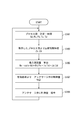
- the compression coefficient specifying unit 21 specifies the compression coefficient Zs on the suction side and the compression coefficient Zd on the discharge side of the gas G compressed by the compression mechanism 10 (S101 in FIG. 3).
- the compression coefficient specifying unit 21 calculates the suction side compression coefficient Zs and the discharge side compression coefficient Zd in order to obtain the suction side pressure gauge 3, the suction side thermometer 4, the discharge side pressure gauge 6, the discharge side thermometer 7, and the discharge side flow rate.
- Information on the suction side gas pressure Ps, the suction side gas temperature Ts, the discharge side gas pressure Pd, and the discharge side gas temperature Td measured in the total 8 is acquired.
- the compression coefficient specifying unit 21 compares the suction side gas pressure Ps, the suction side gas temperature Ts, the discharge side gas pressure Pd, and the discharge side gas temperature Td with the first correspondence information, thereby obtaining the suction side compression coefficient Zs.
- the discharge side compression coefficient Zd is obtained.
- the first correspondence information is stored in the data storage unit 27, and the compression coefficient specifying unit 21 reads the first correspondence information from the data storage unit 27 when obtaining the suction side compression coefficient Zs and the discharge side compression coefficient Zd.
- the first correspondence information in the present embodiment is information in which the pressure, temperature, and compression coefficient in the gas G that includes the saturated water vapor amount and in which the water content is saturated are associated with each other.
- An example is shown in FIG. 4, and this first correspondence information has a form in which the temperature is plotted on a two-dimensional coordinate having the pressure P on the horizontal axis and the compression coefficient Z on the vertical axis. That is, the relationship between the pressure P and the compression coefficient Z corresponding to each of the temperatures T1, T2, T3, T4, and T5 is shown as a diagram.
- the first correspondence information is represented on the two-dimensional coordinates, but the first correspondence information in a table format may be used.
- the first correspondence information may be a function expression.
- the first correspondence information is prepared for each type of gas G to be compressed, and includes the three types of gas types A, B, and C in the example of FIG.
- the compression coefficient specifying unit 21 reads the first correspondence information according to the type of the gas G that is the object of compression.
- the type of the gas G is instructed in advance to the compression coefficient specifying unit 21 from the keyboard which is an input means of the computer device, and the compression coefficient specifying unit 21 reads the first correspondence information corresponding to the type of the gas G in accordance with this instruction. be able to.
- the compression coefficient specifying unit 21 collates the read first correspondence information with the acquired suction side gas pressure Ps, suction side gas temperature Ts, discharge side gas pressure Pd, and discharge side gas temperature Td.
- the discharge side compression coefficient Zd on the diagram corresponding to the discharge side gas pressure Pd and the discharge side gas temperature Td is specified.
- the compression coefficient Z in the first correspondence information is expressed as a function of the pressure and temperature of the moisture saturated state, that is, the gas enriched in moisture. Therefore, the flow rate Qs ⁇ calc calculated using the suction side compression coefficient Zs and the discharge side compression coefficient Zd specified by the compression coefficient specifying unit 21 takes into account the maximum value of the amount of moisture contained in the gas G. The flow rate Qs ⁇ calc close to the actual value can be calculated while maintaining the accuracy of the calculated value of the flow rate in the anti-surge control.
- this information is sent as an electrical signal from the flow rate calculation unit 23 to the control amount specifying unit 25. Then, for example, the control amount specifying unit 25 collates the flow rate Qs ⁇ calc with a performance curve specified by the flow rate Q of gas G and the pressure ratio (Pd / Ps) shown in FIG. 5 to obtain the operating point OP. At this time, the control line CL is considered.
- the control line CL that is, the minimum at which no surge occurs
- the operating point OP is specified by setting a margin M for the suction side flow rate.
- the control amount specifying unit 25 calculates the control amount of the antisurge valve 18 at which the specified operating point OP is obtained, and adjusts the opening when the antisurge valve 18 is opened and closed and opened based on the calculated control amount. To do.
- the suction side pressure gauge 3 and the suction side thermometer 4 provided in the suction line L1 and the suction side gas pressure Ps and the suction of the gas G flowing through the suction line L1
- the side gas temperature Ts is measured.
- the discharge-side pressure gauge 6, the discharge-side thermometer 7 and the discharge-side flow meter 8 provided in the discharge pipe L ⁇ b> 2, the discharge-side gas pressure Pd and the discharge-side gas temperature Td of the gas G flowing through the discharge pipe L ⁇ b> 2.
- the discharge side gas flow rate Qd is measured.
- the measured suction-side gas pressure Ps, suction-side gas temperature Ts, discharge-side gas pressure Pd, discharge-side gas temperature Td, and discharge-side gas flow rate Qd (hereinafter sometimes referred to as process value information) is used to prevent surge generation.
- the data is continuously sent to the compression coefficient specifying unit 21 of the device 20 (S101 in FIG. 3).
- the compression coefficient specifying unit 21 When obtaining the process value information, the compression coefficient specifying unit 21 reads the first correspondence information stored in the data storage unit 27 and collates the process value information (excluding the discharge-side gas flow rate Qd) with the first correspondence information. . Thereby, the compression coefficient specific
- the suction side compression coefficient Zs and the discharge side compression coefficient Zd are sent to the flow rate calculation unit 23, and the flow rate calculation unit 23 substitutes the acquired suction side compression coefficient Zs and discharge side compression coefficient Zd into the equation (2),
- the flow rate is calculated (S105 in FIG. 3).
- the flow rate Qs ⁇ calc is sent to the control amount specifying unit 25.
- Qs ⁇ calc Qd ⁇ Pd / Ps ⁇ Ts / Td ⁇ Zs / Zd (2)
- the control amount specifying unit 25 specifies the control amount by comparing the flow rate Qs ⁇ calc with the performance curve (FIG. 5) (S107 in FIG. 3).
- the control amount specifying unit (opening control unit) 25 issues a command to control the opening of the antisurge valve 18 in accordance with the control amount (S109 in FIG. 3).
- the surge generation preventing device 20 continuously performs the above series of procedures while the compression mechanism 10 is being operated.
- the compressor system 1 measures the flow rate Q by the discharge side flow meter 8 provided on the discharge side of the gas G, the size of the flow meter can be reduced as compared with the measurement on the suction side.
- the configuration described in the above embodiment can be selected or changed to another configuration as appropriate.
- the suction side compression coefficient Zs and the discharge side compression coefficient Zd are specified on the assumption that the moisture of the gas G sucked into the first stage compressor 11 has reached the saturated water vapor amount.
- the water-enriched condition in the present invention is not limited to this, and the suction-side compression coefficient Zs and the discharge-side compression coefficient Zd can be specified with the moisture concentration of the gas G as a constant value.
- the moisture concentration assumed to be constant under the condition where the moisture concentration is enriched is set to a value at which the compression coefficient is shifted most within the operation range of the compressor system 1.
- the compression coefficient Z having the largest deviation from “1.0” as the reference that is, the deviation from the reference value is the largest “0.97” is adopted as the suction side compression coefficient Zs or the discharge side compression coefficient Zd.
- “0.95”, which is the compression coefficient Z having the largest deviation from the reference value “1.0” is adopted as the suction side compression coefficient Zs or the discharge side compression coefficient Zd.
- “1.04”, which is the compression coefficient Z having the largest deviation from the reference value “1.0” is adopted as the suction side compression coefficient Zs or the discharge side compression coefficient Zd.
- the information stored in the data storage unit 27 is as follows. That is, in the table-type pressure-temperature-compression coefficient correspondence information shown in FIG. 6, the data storage unit is information (second correspondence information) in which the compression coefficient Zd having the largest deviation from the reference value is associated with the gas type. 27.
- the gas type A in the case of the gas type A, the gas type A and the compression coefficient Z “0.97” are associated with each other and stored in the data storage unit 27.
- the compression coefficient specifying unit 21 reads the compression coefficient Z “0.9” in accordance with this instruction, and performs the suction side compression coefficient Zs and the discharge. This is sent to the flow rate calculation unit 23 as the side compression coefficient Zd.
- the flow rate calculation unit 23 calculates the flow rate by substituting the acquired suction side compression coefficient Zs and discharge side compression coefficient Zd into the above-described equation (2), and sends it to the control amount specifying unit 25.
- the control amount specifying unit 25 adjusts the opening when the anti-surge valve 18 is opened and closed and opened according to the procedure described above.
- anti-surge control it is possible to adopt a method in which the anti-surge valve is always open and its opening degree is adjusted. Including this method, the present invention controls the opening of the antisurge valve.
Landscapes
- Engineering & Computer Science (AREA)
- Mechanical Engineering (AREA)
- General Engineering & Computer Science (AREA)
- Control Of Positive-Displacement Air Blowers (AREA)
Abstract
サージ発生防止装置20は、ガスGを圧縮する圧縮機の吸込側ガス圧力Psと吸込側ガス温度Tsと吐出側ガス圧力Pdと吐出側ガス温度Tdと吐出側ガス流量Qdの各情報を取得し、ガスGの吸込側圧縮係数ZsとガスGの吐出側圧縮係数Zdを特定する圧縮係数特定部21と、吸込側圧縮係数Zs及び吐出側圧縮係数Zdが特定されると、吸込側ガス流量Qs・calcを下記の式(2)に基づいて算出する流量算出部23と、算出されたQs・calcに基づいて、アンチサージ弁の開度を制御する制御量特定部(開度制御部)25と、を備える。圧縮係数特定部21は、水分濃度が富化された条件における吸込側圧縮係数Zsと吐出側圧縮係数Zdを特定することを特徴とする。Qs・calc = Qd×Pd/Ps×Ts/Td×Zs/Zd … (2)
Description
本発明は、圧縮機、特に複数段の圧縮機を備える場合にサージの発生を防止する装置およびこれを備える圧縮機システムに関する。
上流に位置するプラントの負荷変化や圧縮機のトリップなどの現象が起きた際に、圧縮機への流量が少なくなると、周期的な強い圧力変動が生じる現象、すなわちサージ現象が発生して圧縮機が損傷する可能性がある。サージを防ぐために、緊急時にも圧縮機へと最低限の流量の流体を流すべく、圧縮機の吸込側と吐出側を接続したバイパス流路を設けるとともに、バイパス流路に流量を制御するアンチサージ弁を設ける。そして、サージの発生が予想されると、アンチサージ弁を開いて、吐出側のガスを吸込側へ戻して、吸込流量を増加させる。または、通常運転時から、圧縮機への流量が少なくなりすぎないよう、アンチサージ弁の開度を制御するアンチサージ制御が行われる。
圧縮機におけるサージ発生防止について、特許文献1は、圧縮機の吸込側流量Qsと吸込側圧力Psと吸込側温度Tsと吐出側圧力Pdと吐出側温度Tdの各情報を取得し、ポリトロープヘッドを算出し、算出されたポリトロープヘッド値を基にガスの分子量を推定するなどして、サージが発生するか否かを判定することを提案している。
ここで、ガスの流量は、特許文献1のように圧縮機の吸込側で測定できるが、吐出側で測定することもできる。吐出側は吸込側に比べてガスが圧縮されているので、小さいサイズの流量計を用いることができるので、コスト的に有利である。コスト面から考えると、流量計はガスが圧縮され、小さいサイズを選択できる吐出側に設置することが好ましい。なお、吐出側で測定したガスの流量から吸込側のガスの流量(Qs・calc)を求めるには、吐出側のガスの流量(Qd)、圧力(Pd)、温度(Td)、及び、吸込側の流体の圧力(Ps)、温度(Ts)を測定しておき、下記の式(1)を用いて計算する。
Qs・calc = Qd×Pd/Ps×Ts/Td… (1)
Qs・calc = Qd×Pd/Ps×Ts/Td… (1)
しかし、式(1)により求められるQs・calcは、圧縮機を複数備える多段圧縮機構において、以下の問題がある。つまり、多段の圧縮機を順番に経る度に吐出側のガスに含まれる水分の量が減少するので、吐出側のガスの水分量は吸込側のガスの水分量に比べて少なくなる。また、多段の圧縮機を順番に経ることでガスが高圧になるにつれて、吐出側のガスの圧縮係数が吸込側のガスの圧縮係数からずれてしまう。これらの理由により、式(1)を用いて吐出側の流量から吸込側の流量(Qs・calc)を計算すると、実際の流量からずれた値になってしまう。
以上より、本発明は、吐出側の流量から吸込側の流量(Qs・calc)を高い精度で求めることができる圧縮機のサージ発生防止装置を提供することを目的とする。また、本発明は、そのようなサージ発生防止装置を備えることで、サージの発生を高い精度で防止できる多段の圧縮機を備える圧縮機システム提供することを目的とする。
本発明のサージ発生防止装置は、ガスを圧縮する圧縮機の吸込側ガス圧力Psと吸込側ガス温度Tsと吐出側ガス圧力Pdと吐出側ガス温度Tdと吐出側ガス流量Qdの各情報を取得し、ガスの吸込側圧縮係数Zsとガスの吐出側圧縮係数Zdを特定するように構成される圧縮係数特定部と、吸込側圧縮係数Zs及び吐出側圧縮係数Zdが特定されると、吸込側ガス流量Qs・calcを下記の式(2)に基づいて算出するように構成される流量算出部と、算出された吸込側流量Qs・calcに基づいて、アンチサージ弁の開度を制御するように構成される開度制御部と、を備え、圧縮係数特定部は、水分濃度が富化された条件における吸込側圧縮係数Zsと吐出側圧縮係数Zdを特定する、ことを特徴とする。
Qs・calc = Qd×Pd/Ps×Ts/Td×Zs/Zd … (2)
Qs・calc = Qd×Pd/Ps×Ts/Td×Zs/Zd … (2)
本発明のサージ発生防止装置において、吸込側圧縮係数Zsと吐出側圧縮係数Zdを特定する形態を、少なくとも二つ含む。
一つ目の形態による圧縮係数特定部は、水分が飽和状態における吸込側ガス圧力Ps及び吸込側ガス温度Tsに対応する吸込側圧縮係数Zsと、水分が飽和状態における吐出側ガス圧力Pd及び吐出側ガス温度Tdに対応する吐出側圧縮係数Zdと、を特定するというものである。
一つ目の形態は、水分が飽和状態のガスにおける圧力と温度と圧縮係数とが対応付けられた情報である第一対応情報を記憶する記憶部を備え、圧縮係数特定部が、吸込側ガス圧力Ps、吸込側ガス温度Ts、吐出側ガス圧力Pd及び吐出側ガス温度Tdを取得すると、第一対応情報と照合することで、ガスの吸込側圧縮係数Zsと吐出側圧縮係数Zdを特定する、ことができる。
一つ目の形態による圧縮係数特定部は、水分が飽和状態における吸込側ガス圧力Ps及び吸込側ガス温度Tsに対応する吸込側圧縮係数Zsと、水分が飽和状態における吐出側ガス圧力Pd及び吐出側ガス温度Tdに対応する吐出側圧縮係数Zdと、を特定するというものである。
一つ目の形態は、水分が飽和状態のガスにおける圧力と温度と圧縮係数とが対応付けられた情報である第一対応情報を記憶する記憶部を備え、圧縮係数特定部が、吸込側ガス圧力Ps、吸込側ガス温度Ts、吐出側ガス圧力Pd及び吐出側ガス温度Tdを取得すると、第一対応情報と照合することで、ガスの吸込側圧縮係数Zsと吐出側圧縮係数Zdを特定する、ことができる。
二つ目の形態による圧縮係数特定部は、一定値の水分濃度に基づいてガスの吸込側圧縮係数Zsと吐出側圧縮係数Zdを特定する、と言うものである。
二つ目の形態は、ガスにおける基準値との偏差が最も大きい圧縮係数である第二対応情報を記憶する記憶部を備え、圧縮係数特定部は、基準値との偏差が最も大きい圧縮係数を、吸込側圧縮係数Zsと吐出側圧縮係数Zdに特定する、ことができる。
二つ目の形態は、ガスにおける基準値との偏差が最も大きい圧縮係数である第二対応情報を記憶する記憶部を備え、圧縮係数特定部は、基準値との偏差が最も大きい圧縮係数を、吸込側圧縮係数Zsと吐出側圧縮係数Zdに特定する、ことができる。
本発明のサージ発生防止装置は、ガスを圧縮する複数段の圧縮機を備える圧縮機構を備える圧縮機システムに好適に適用される。この圧縮機構は、最も上流側に位置する圧縮機にガスを供給する吸込管路と、最も下流側に位置する圧縮機からのガスが吐出される吐出管路と、吸込管路と吐出管路との間に接続され、吐出管路を流れるガスの一部を吸込管路に戻すバイパス管路と、バイパス管路に設けられ、吸込管路に戻されるガスの流量を調整するアンチサージ弁と、を備える。そして、このアンチサージ弁は、本発明によるサージ発生防止装置によりその開度が制御されることを特徴とする。
本発明のサージ発生防止装置によれば、アンチサージ制御を安全サイドに機能させることを考慮し、吸込側ガスは水分が富化された状態と仮定して吸込側圧縮係数Zsと吐出側圧縮係数Zdを特定する。これにより、アンチサージ制御における流量の計算値の精度は保ちつつ、実際の流量に近い吸込側ガス流量Qs・calcを算出できる。
以下、添付図面を参照しながら、本発明の実施形態に係るサージ発生防止装置20を適用した圧縮機システム1について説明する。
圧縮機システム1は、図1に示すように、ガスGを圧縮する複数段の圧縮機を備える圧縮機構10と、圧縮機構10のサージの発生を抑制するサージ発生防止装置20と、を備えている。なお、圧縮機システム1において、圧縮の対象となるガスGが流れる向きを基準にして、上流及び下流が定義される。
圧縮機システム1は、図1に示すように、ガスGを圧縮する複数段の圧縮機を備える圧縮機構10と、圧縮機構10のサージの発生を抑制するサージ発生防止装置20と、を備えている。なお、圧縮機システム1において、圧縮の対象となるガスGが流れる向きを基準にして、上流及び下流が定義される。
[圧縮機構10]
圧縮機構10は、第一段圧縮機11、第二段圧縮機12、第三段圧縮機13及び第四段圧縮機14と、複数段の圧縮機を備える。それぞれの圧縮機は例えば遠心圧縮機からなり、ガスGは、最も上流側に配置される第一段圧縮機11から第二段圧縮機12、第三段圧縮機13及び第四段圧縮機14の順に所望される圧力まで昇圧される。
第一段圧縮機11、第二段圧縮機12及び第三段圧縮機13のそれぞれのガスGの上流側、つまり吸込側には、ガスGの吸込量を調整する吸込調整弁15が設けられている。
圧縮機構10は、第一段圧縮機11、第二段圧縮機12、第三段圧縮機13及び第四段圧縮機14と、複数段の圧縮機を備える。それぞれの圧縮機は例えば遠心圧縮機からなり、ガスGは、最も上流側に配置される第一段圧縮機11から第二段圧縮機12、第三段圧縮機13及び第四段圧縮機14の順に所望される圧力まで昇圧される。
第一段圧縮機11、第二段圧縮機12及び第三段圧縮機13のそれぞれのガスGの上流側、つまり吸込側には、ガスGの吸込量を調整する吸込調整弁15が設けられている。
最も上流側の第一段圧縮機11に付属する吸込調整弁15の吸込側には、ガスGを吸込むための吸込管路L1が接続されている。吸込管路L1には、ガスGの供給源である例えばプラント設備からガスGが送り込まれる。また、最も下流側の第四段圧縮機14には吐出管路L2が接続されている。吐出管路L2は、昇圧されたガスGを利用する例えばプラント設備に向けてガスGを送り出す。
吸込管路L1には、吸込側圧力計3と吸込側温度計4が設置されている。吸込側圧力計3と吸込側温度計4とは、それぞれ吸込管路L1を流れるガスGの吸込側圧力Psと吸込側温度Tsとを継続して測定する。
吐出管路L2には、吐出側圧力計6、吐出側温度計7及び吐出側流量計8が設置されている。吐出側圧力計6、吐出側温度計7及び吐出側流量計8は、それぞれ吐出管路L2を流れるガスGの吐出側ガス圧力Pd、吐出側ガス温度Td及び吐出側ガス流量Qdを継続して測定する。
測定された吸込側の圧力Ps、温度Tsに関する情報と、測定された吐出側の圧力Pd、温度Td及び流量Qdに関する情報は、電気信号としてサージ発生防止装置20に送られる。
吐出管路L2には、吐出側圧力計6、吐出側温度計7及び吐出側流量計8が設置されている。吐出側圧力計6、吐出側温度計7及び吐出側流量計8は、それぞれ吐出管路L2を流れるガスGの吐出側ガス圧力Pd、吐出側ガス温度Td及び吐出側ガス流量Qdを継続して測定する。
測定された吸込側の圧力Ps、温度Tsに関する情報と、測定された吐出側の圧力Pd、温度Td及び流量Qdに関する情報は、電気信号としてサージ発生防止装置20に送られる。
第一段圧縮機11と第二段圧縮機12は第一接続管路L12で接続され、第二段圧縮機12と第三段圧縮機13は第二接続管路L23で接続され、第三段圧縮機13と第四段圧縮機14は、第三接続管路L34で接続されている。第一段圧縮機11で圧縮されたガスGは、第一接続管路L12を通って第二段圧縮機12に吸込まれ、第二段圧縮機12で圧縮されたガスGは、第二接続管路L23を通って第三段圧縮機13に吸込まれ、第三段圧縮機13で圧縮されたガスGは、第三接続管路L34を通って第四段圧縮機14に吸込まれる。
第一接続管路L12、第二接続管路L23及び第三接続管路L34のそれぞれには、冷却機能及び除湿機能を備えるドレインセパレータ17が設けられている。第一段圧縮機11、第二段圧縮機12、第三段圧縮機13で圧縮されたガスGは、圧縮により生じた熱がこのドレインセパレータ17を通過することで冷却され、さらにこの冷却によって結露した水分がドレイン(drain)として外部に排出される。なお、ここでは冷却機能及び除湿機能を備えるドレインセパレータ17を用いているが、冷却機能を備える機器と除湿機能を備える機器を独立して設けることもできる。
吸込管路L1と吐出管路L2との間には、サージの発生を予防または抑制するために、圧縮機構10から吐出されるガスGの一部を吸込側に戻すバイパス管路L3が接続されている。バイパス管路L3には、サージの発生を予防または抑制する際に開かれる制御弁であるアンチサージ弁18が設けられている。アンチサージ弁18は、常時は閉じられているが、サージの発生を予防する必要があるときに開かれるものとする。
[サージ発生防止装置20]
サージ発生防止装置20は、吸込側圧力計3、吸込側温度計4、吐出側圧力計6、吐出側温度計7及び吐出側流量計8で測定された吸込側ガス圧力Ps、吸込側ガス温度Ts、吐出側ガス圧力Pd、吐出側ガス温度Td及び吐出側ガス流量Qdを用いて、吸込側のガスGの流量Qs・calcを算出により求める。次いで、サージ発生防止装置20は、流量Qs・calcに基づいて、アンチサージ弁18の制御量を特定し、特定された制御量でアンチサージ弁18を動作させる。この手順を行うために、サージ発生防止装置20は以下の構成を備える。
なお、サージ発生防止装置20は、処理装置であるCPU(Central Processing Unit)とROM(Read Only Memory)、RAM(Random Access Memory)などのメモリ手段と、を含むコンピュータ装置によって実現される。
サージ発生防止装置20は、吸込側圧力計3、吸込側温度計4、吐出側圧力計6、吐出側温度計7及び吐出側流量計8で測定された吸込側ガス圧力Ps、吸込側ガス温度Ts、吐出側ガス圧力Pd、吐出側ガス温度Td及び吐出側ガス流量Qdを用いて、吸込側のガスGの流量Qs・calcを算出により求める。次いで、サージ発生防止装置20は、流量Qs・calcに基づいて、アンチサージ弁18の制御量を特定し、特定された制御量でアンチサージ弁18を動作させる。この手順を行うために、サージ発生防止装置20は以下の構成を備える。
なお、サージ発生防止装置20は、処理装置であるCPU(Central Processing Unit)とROM(Read Only Memory)、RAM(Random Access Memory)などのメモリ手段と、を含むコンピュータ装置によって実現される。
サージ発生防止装置20は、図2に示すように、圧縮係数特定部21、流量算出部23、制御量特定部25及びデータ記憶部27と、を備えている。これら圧縮係数特定部21、流量算出部23、制御量特定部25及びデータ記憶部27の各機能は、ソフトウェアによって具現化できる。
圧縮係数特定部21は、圧縮機構10で圧縮されるガスGの吸込側の圧縮係数Zsと吐出側の圧縮係数Zdを特定する(図3 S101)。
圧縮係数特定部21は、吸込側圧縮係数Zsと吐出側圧縮係数Zdを求めるのに、吸込側圧力計3、吸込側温度計4、吐出側圧力計6、吐出側温度計7及び吐出側流量計8で測定された吸込側ガス圧力Ps、吸込側ガス温度Ts、吐出側ガス圧力Pd及び吐出側ガス温度Tdに関する情報を取得する。圧縮係数特定部21は、取得した吸込側ガス圧力Ps、吸込側ガス温度Ts、吐出側ガス圧力Pd及び吐出側ガス温度Tdを、第一対応情報と照合することで、吸込側圧縮係数Zsと吐出側圧縮係数Zdを求める。
圧縮係数特定部21は、吸込側圧縮係数Zsと吐出側圧縮係数Zdを求めるのに、吸込側圧力計3、吸込側温度計4、吐出側圧力計6、吐出側温度計7及び吐出側流量計8で測定された吸込側ガス圧力Ps、吸込側ガス温度Ts、吐出側ガス圧力Pd及び吐出側ガス温度Tdに関する情報を取得する。圧縮係数特定部21は、取得した吸込側ガス圧力Ps、吸込側ガス温度Ts、吐出側ガス圧力Pd及び吐出側ガス温度Tdを、第一対応情報と照合することで、吸込側圧縮係数Zsと吐出側圧縮係数Zdを求める。
第一対応情報は、データ記憶部27に記憶されており、圧縮係数特定部21は吸込側圧縮係数Zsと吐出側圧縮係数Zdを求める際に、データ記憶部27から第一対応情報を読み出す。
ここで、本実施形態における第一対応情報は、飽和水蒸気量を含み水分が飽和状態のガスGにおける圧力と温度と圧縮係数とが対応付けられた情報である。一例を図4に示すが、この第一対応情報は、横軸が圧力Pで縦軸が圧縮係数Zの二次元座標上に、温度をプロットした形態を有している。つまり、温度T1,T2,T3,T4,T5ごとに対応する圧力Pと圧縮係数Zの関係が線図として表されている。なお、ここでは二次元座標上に第一対応情報を表してしているが、テーブル形式の第一対応情報でもよい。また、第一対応情報は、関数式であってもよい。
ここで、本実施形態における第一対応情報は、飽和水蒸気量を含み水分が飽和状態のガスGにおける圧力と温度と圧縮係数とが対応付けられた情報である。一例を図4に示すが、この第一対応情報は、横軸が圧力Pで縦軸が圧縮係数Zの二次元座標上に、温度をプロットした形態を有している。つまり、温度T1,T2,T3,T4,T5ごとに対応する圧力Pと圧縮係数Zの関係が線図として表されている。なお、ここでは二次元座標上に第一対応情報を表してしているが、テーブル形式の第一対応情報でもよい。また、第一対応情報は、関数式であってもよい。
第一対応情報は、圧縮の対象となるガスGの種類ごとに用意され、図4の例では、ガス種別A,B,Cの三種類を含んでいる。圧縮係数特定部21は、圧縮の対象となっているガスGの種別に応じて、第一対応情報を読み出す。ガスGの種別は、コンピュータ装置の入力手段であるキーボードからあらかじめ圧縮係数特定部21に指示しておき、圧縮係数特定部21はこの指示に従って、ガスGの種別に応じた第一対応情報を読み出すことができる。
圧縮係数特定部21は、読み出した第一対応情報と、取得した吸込側ガス圧力Ps、吸込側ガス温度Ts、吐出側ガス圧力Pd及び吐出側ガス温度Tdを照合する。例えば、図4において、吸込側ガス圧力Psと吸込側ガス温度Ts(=T)に対応する線図上の吸込側圧縮係数Zsが特定される(図3
S103)。同様にして、吐出側ガス圧力Pd及び吐出側ガス温度Tdに対応する線図上の吐出側圧縮係数Zdが特定される。
S103)。同様にして、吐出側ガス圧力Pd及び吐出側ガス温度Tdに対応する線図上の吐出側圧縮係数Zdが特定される。
吸込側圧縮係数Zs及び吐出側圧縮係数Zdが特定されると、この情報は電気信号として、圧縮係数特定部21から流量算出部23に送られる。そうすると、流量算出部23は、式(2)を用いて流量Qs・calcを算出する(図3 S105)。
Qs・calc = Qd×Pd/Ps×Ts/Td×Zs/Zd … (2)
Qs・calc = Qd×Pd/Ps×Ts/Td×Zs/Zd … (2)
ここで、第一対応情報における圧縮係数Zは、水分が飽和状態、つまり水分が富化されたガスの圧力・温度の関数で表されている。したがって、圧縮係数特定部21で特定された吸込側圧縮係数Zs及び吐出側圧縮係数Zdを用いて算出された流量Qs・calcは、ガスGに含まれる水分量の最大値を考慮しているため、アンチサージ制御における流量の計算値の精度は保ちつつ、実際に近い流量Qs・calcが計算できる。
流量Qs・calcが算出されると、この情報は電気信号として、流量算出部23から制御量特定部25に送られる。そうすると、制御量特定部25は、例えば図5に示されるガスGの流量Qと圧力比(Pd/Ps)で特定される性能曲線に流量Qs・calcを照合し、運転点OPを求める。この際に、コントロールラインCLを考慮する。つまり、閾値であるコントロールラインCLより左の領域ではサージが発生し、コントロールラインCLを含みそれよりも右の領域だとサージが発生しないものとすると、コントロールラインCL、つまりサージが発生しない最小の吸込み側の流量にマージンMを設定して運転点OPを特定する。
制御量特定部25は、特定された運転点OPが得られるアンチサージ弁18の制御量を算出し、算出された制御量に基づいて、アンチサージ弁18の開閉及び開く場合の開度を調整するように指令する。
[圧縮機システム1の動作]
次に、圧縮機システム1の動作について、図1~図3を用いて説明する。
上流に位置するプラントからガスGが吸込管路L1に供給されると、ガスGは第一段圧縮機11、第二段圧縮機12、第三段圧縮機13及び第四段圧縮機14の順に圧縮されてから吐出管路L2に吐出される。この過程において、第一接続管路L12、第二接続管路L23及び第三接続管路L34のそれぞれに設けられるドレインセパレータ17によって、ガスGから水分がドレインとして除去されるので、第四段圧縮機14から吐出されるガスGの水分は第一段圧縮機11に吸込まれるガスGに比べて少ない。
次に、圧縮機システム1の動作について、図1~図3を用いて説明する。
上流に位置するプラントからガスGが吸込管路L1に供給されると、ガスGは第一段圧縮機11、第二段圧縮機12、第三段圧縮機13及び第四段圧縮機14の順に圧縮されてから吐出管路L2に吐出される。この過程において、第一接続管路L12、第二接続管路L23及び第三接続管路L34のそれぞれに設けられるドレインセパレータ17によって、ガスGから水分がドレインとして除去されるので、第四段圧縮機14から吐出されるガスGの水分は第一段圧縮機11に吸込まれるガスGに比べて少ない。
以上のガスGの圧縮を継続している間に、吸込管路L1に設けられ吸込側圧力計3及び吸込側温度計4により、吸込管路L1を流れるガスGの吸込側ガス圧力Ps及び吸込側ガス温度Tsが測定される。また、吐出管路L2に設けられている吐出側圧力計6、吐出側温度計7及び吐出側流量計8により、吐出管路L2を流れるガスGの吐出側ガス圧力Pd、吐出側ガス温度Td及び吐出側ガス流量Qdが測定される。測定された吸込側ガス圧力Ps、吸込側ガス温度Ts、吐出側ガス圧力Pd、吐出側ガス温度Td及び吐出側ガス流量Qdに関する情報(以下、プロセス値情報ということがある)は、サージ発生防止装置20の圧縮係数特定部21に継続的に送られる(図3 S101)。
圧縮係数特定部21は、プロセス値情報を取得すると、データ記憶部27に記憶されている第一対応情報を読み出し、プロセス値情報(吐出側ガス流量Qdを除く)を第一対応情報と照合する。これにより、圧縮係数特定部21は吸込側圧縮係数Zs及び吐出側圧縮係数Zdを特定する(図3 S103)。
吸込側圧縮係数Zs及び吐出側圧縮係数Zdは流量算出部23に送られ、流量算出部23は、取得した吸込側圧縮係数Zs及び吐出側圧縮係数Zdを式(2)に代入することで、流量を算出する(図3 S105)。流量Qs・calcは、制御量特定部25に送られる。
Qs・calc = Qd×Pd/Ps×Ts/Td×Zs/Zd … (2)
Qs・calc = Qd×Pd/Ps×Ts/Td×Zs/Zd … (2)
制御量特定部25は、流量Qs・calcを性能曲線(図5)と照合することで、制御量を特定する(図3 S107)。制御量特定部(開度制御部)25は、制御量に応じてアンチサージ弁18の開度を制御するように指令を出す(図3 S109)。
サージ発生防止装置20は、以上の一連の手順を、圧縮機構10が運転されている間に、継続して行う。
サージ発生防止装置20は、以上の一連の手順を、圧縮機構10が運転されている間に、継続して行う。
[圧縮機システム1の効果]
次に、圧縮機システム1のサージ発生防止装置20による効果を説明する。
圧縮機システム1は、水分が飽和状態、水分が富化された条件として、水分が飽和状態における吸込側ガス圧力Ps及び吸込側ガス温度Tsに対応する吸込側圧縮係数Zsと、水分が飽和状態における吐出側ガス圧力Pd及び吐出側ガス温度Tdに対応する吐出側圧縮係数Zdを用いて吸込側ガス流量Qs・calcを求める。そして、このガスGに含まれる水分量の最大値を考慮した吸込側流量Qs・calcに基づいてアンチサージ弁18の開度を制御するので、アンチサージ制御における流量の計算値の精度は保ちつつ、サージの発生を高い精度で防止できる。
また、圧縮機システム1によれば、計算した吸込側ガス流量Qs・calcのずれが小さくなるため、負荷が下がりアンチサージ制御が働く状況になっても、余分な動力を消費せずに、圧縮機を運転できる。
次に、圧縮機システム1のサージ発生防止装置20による効果を説明する。
圧縮機システム1は、水分が飽和状態、水分が富化された条件として、水分が飽和状態における吸込側ガス圧力Ps及び吸込側ガス温度Tsに対応する吸込側圧縮係数Zsと、水分が飽和状態における吐出側ガス圧力Pd及び吐出側ガス温度Tdに対応する吐出側圧縮係数Zdを用いて吸込側ガス流量Qs・calcを求める。そして、このガスGに含まれる水分量の最大値を考慮した吸込側流量Qs・calcに基づいてアンチサージ弁18の開度を制御するので、アンチサージ制御における流量の計算値の精度は保ちつつ、サージの発生を高い精度で防止できる。
また、圧縮機システム1によれば、計算した吸込側ガス流量Qs・calcのずれが小さくなるため、負荷が下がりアンチサージ制御が働く状況になっても、余分な動力を消費せずに、圧縮機を運転できる。
また、圧縮機システム1は、ガスGの吐出側に設けられた吐出側流量計8により流量Qを測定するので、吸込側で測定するのに比べて、流量計のサイズを小さくできる。
上記以外にも、本発明の主旨を逸脱しない限り、上記実施形態で挙げた構成を取捨選択したり、他の構成に適宜変更したりすることが可能である。
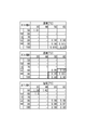
以上の形態は、第一段圧縮機11に吸込まれるガスGの水分が飽和水蒸気量に達しているものと仮定して吸込側圧縮係数Zs及び吐出側圧縮係数Zdを特定した。しかし、本発明における水分が富化された条件とはこれに限らず、ガスGの水分濃度を一定値として吸込側圧縮係数Zs及び吐出側圧縮係数Zdを特定することもできる。水分濃度が富化された条件においてこの一定と仮定する水分濃度は、圧縮機システム1の運転範囲内で圧縮係数が最もずれた値に設定される。例えば、図6のテーブル形式の圧力-温度-圧縮係数対応情報において、上段のテーブルにおいては、基準となる「1.0」から最もずれの大きい、つまり基準値との偏差が最も大きい圧縮係数Zである「0.97」を吸込側圧縮係数Zs又は吐出側圧縮係数Zdとして採用する。同様に、中段のテーブルにおいて、基準値である「1.0」との偏差が最も大きい圧縮係数Zである「0.95」を吸込側圧縮係数Zs又は吐出側圧縮係数Zdとして採用する。さらに、下段のテーブルにおいて、基準値である「1.0」との偏差が最も大きい圧縮係数Zである「1.04」を吸込側圧縮係数Zs又は吐出側圧縮係数Zdとして採用する。
この吸込側圧縮係数Zs及び吐出側圧縮係数Zdの特定手法は、水分の飽和状態を考慮せず、一定値を用いるために演算を簡略化できる。
以上の形態は、第一段圧縮機11に吸込まれるガスGの水分が飽和水蒸気量に達しているものと仮定して吸込側圧縮係数Zs及び吐出側圧縮係数Zdを特定した。しかし、本発明における水分が富化された条件とはこれに限らず、ガスGの水分濃度を一定値として吸込側圧縮係数Zs及び吐出側圧縮係数Zdを特定することもできる。水分濃度が富化された条件においてこの一定と仮定する水分濃度は、圧縮機システム1の運転範囲内で圧縮係数が最もずれた値に設定される。例えば、図6のテーブル形式の圧力-温度-圧縮係数対応情報において、上段のテーブルにおいては、基準となる「1.0」から最もずれの大きい、つまり基準値との偏差が最も大きい圧縮係数Zである「0.97」を吸込側圧縮係数Zs又は吐出側圧縮係数Zdとして採用する。同様に、中段のテーブルにおいて、基準値である「1.0」との偏差が最も大きい圧縮係数Zである「0.95」を吸込側圧縮係数Zs又は吐出側圧縮係数Zdとして採用する。さらに、下段のテーブルにおいて、基準値である「1.0」との偏差が最も大きい圧縮係数Zである「1.04」を吸込側圧縮係数Zs又は吐出側圧縮係数Zdとして採用する。
この吸込側圧縮係数Zs及び吐出側圧縮係数Zdの特定手法は、水分の飽和状態を考慮せず、一定値を用いるために演算を簡略化できる。
ここで、ガスGの水分濃度を一定値として吸込側圧縮係数Zs及び吐出側圧縮係数Zdを特定する手法の場合には、データ記憶部27に記憶される情報は以下の通りである。つまり、図6に示すテーブル形式の圧力-温度-圧縮係数対応情報の中で、基準値との偏差が最も大きい圧縮係数Zdがガス種と対応付けた情報(第二対応情報)としてデータ記憶部27に記憶される。例えば、図6において、ガス種Aの場合、ガス種Aと圧縮係数Z「0.97」とが対応付けられてデータ記憶部27に記憶される。
この場合、ガス種Aが、上述した手順で圧縮係数特定部21に指示されると、圧縮係数特定部21はこの指示に従って圧縮係数Z「0.9」を読み出し、吸込側圧縮係数Zs及び吐出側圧縮係数Zdとして流量算出部23に送る。流量算出部23は、取得した吸込側圧縮係数Zs及び吐出側圧縮係数Zdを前述した式(2)に代入することで流量を算出するとともに、制御量特定部25に送る。制御量特定部25は、上述した手順により、アンチサージ弁18の開閉及び開く場合の開度を調整する。
この場合、ガス種Aが、上述した手順で圧縮係数特定部21に指示されると、圧縮係数特定部21はこの指示に従って圧縮係数Z「0.9」を読み出し、吸込側圧縮係数Zs及び吐出側圧縮係数Zdとして流量算出部23に送る。流量算出部23は、取得した吸込側圧縮係数Zs及び吐出側圧縮係数Zdを前述した式(2)に代入することで流量を算出するとともに、制御量特定部25に送る。制御量特定部25は、上述した手順により、アンチサージ弁18の開閉及び開く場合の開度を調整する。
また、アンチサージ制御については、アンチサージ弁が常時開かれており、その開度を調整するという方式を採用することもできる。この方式を含めて、本発明はアンチサージ弁の開度を制御するという。
1 圧縮機システム
3 吸込側圧力計
4 吸込側温度計
6 吐出側圧力計
7 吐出側温度計
8 吐出側流量計
10 圧縮機構
11 第一段圧縮機
12 第二段圧縮機
13 第三段圧縮機
14 第四段圧縮機
15 吸込調整弁
17 ドレインセパレータ
18 アンチサージ弁
20 サージ発生防止装置
21 圧縮係数特定部
23 流量算出部
25 制御量特定部
27 データ記憶部
G ガス
3 吸込側圧力計
4 吸込側温度計
6 吐出側圧力計
7 吐出側温度計
8 吐出側流量計
10 圧縮機構
11 第一段圧縮機
12 第二段圧縮機
13 第三段圧縮機
14 第四段圧縮機
15 吸込調整弁
17 ドレインセパレータ
18 アンチサージ弁
20 サージ発生防止装置
21 圧縮係数特定部
23 流量算出部
25 制御量特定部
27 データ記憶部
G ガス
Claims (6)
- ガスを圧縮する圧縮機の吸込側ガス圧力Psと吸込側ガス温度Tsと吐出側ガス圧力Pdと吐出側ガス温度Tdと吐出側ガス流量Qdの各情報を取得し、前記ガスの吸込側圧縮係数Zsと前記ガスの吐出側圧縮係数Zdを特定するように構成される圧縮係数特定部と、
前記吸込側圧縮係数Zs及び前記吐出側圧縮係数Zdが特定されると、吸込側ガス流量Qs・calcを下記の式(2)に基づいて算出するように構成される流量算出部と、
算出された前記吸込側ガス流量Qs・calcに基づいて、アンチサージ弁の開度を制御するように構成される開度制御部と、を備え、
前記圧縮係数特定部は、
水分濃度が富化された条件における前記吸込側圧縮係数Zsと前記吐出側圧縮係数Zdを特定するように構成される、ことを特徴とするサージ発生防止装置。
Qs・calc = Qd×Pd/Ps×Ts/Td×Zs/Zd … (2) - 前記圧縮係数特定部は、
水分が飽和状態における前記吸込側圧力Ps及び前記吸込側温度Tsに対応する前記吸込側圧縮係数Zsと、
水分が飽和状態における前記吐出側圧力Pd及び前記吐出側温度Tdに対応する前記吐出側圧縮係数Zdと、を特定する、
請求項1に記載のサージ発生防止装置。 - 水分が飽和状態の前記ガスにおける圧力と温度と圧縮係数とが対応付けられた情報である第一対応情報を記憶する記憶部を備え、
前記圧縮係数特定部は、
前記吸込側ガス圧力Ps、前記吸込側ガス温度Ts、前記吐出側ガス圧力Pd及び前記吐出側ガス温度Tdを取得すると、前記第一対応情報と照合することで、前記吸込側圧縮係数Zsと前記吐出側圧縮係数Zdを特定する、
請求項2に記載のサージ発生防止装置。 - 前記圧縮係数特定部は、
一定値の水分濃度に基づいて前記吸込側圧縮係数Zsと前記吐出側圧縮係数Zdを特定する、
請求項1に記載のサージ発生防止装置。 - 前記ガスにおける基準値との偏差が最も大きい圧縮係数である第二対応情報を記憶する記憶部を備え、
前記圧縮係数特定部は、
基準値との偏差が最も大きい前記圧縮係数を、前記吸込側圧縮係数Zsと前記吐出側圧縮係数Zdとして特定する、
請求項4に記載のサージ発生防止装置。 - ガスを圧縮する複数段の圧縮機を備える圧縮機構と、
前記圧縮機構のサージの発生を抑制する、請求項1~請求項5のいずれか一項に記載のサージ発生防止装置と、を備える圧縮機システムであって、
前記圧縮機構は、
最も上流側に位置する前記圧縮機に前記ガスを供給する吸込管路と、
最も下流側に位置する前記圧縮機からの前記ガスが吐出される吐出管路と、
前記吸込管路と前記吐出管路との間に接続され、前記吐出管路を流れる前記ガスの一部を前記吸込管路に戻すバイパス管路と、
前記バイパス管路に設けられ、前記吸込管路に戻される前記ガスの流量を調整するアンチサージ弁と、を備え、
前記アンチサージ弁の開度が、前記サージ発生防止装置により制御される
ことを特徴とする圧縮機システム。
Applications Claiming Priority (2)
| Application Number | Priority Date | Filing Date | Title |
|---|---|---|---|
| JP2016-022226 | 2016-02-08 | ||
| JP2016022226A JP2017141698A (ja) | 2016-02-08 | 2016-02-08 | 圧縮機のサージ発生防止装置および圧縮機システム |
Publications (1)
| Publication Number | Publication Date |
|---|---|
| WO2017138481A1 true WO2017138481A1 (ja) | 2017-08-17 |
Family
ID=59563777
Family Applications (1)
| Application Number | Title | Priority Date | Filing Date |
|---|---|---|---|
| PCT/JP2017/004172 Ceased WO2017138481A1 (ja) | 2016-02-08 | 2017-02-06 | 圧縮機のサージ発生防止装置および圧縮機システム |
Country Status (2)
| Country | Link |
|---|---|
| JP (1) | JP2017141698A (ja) |
| WO (1) | WO2017138481A1 (ja) |
Cited By (1)
| Publication number | Priority date | Publication date | Assignee | Title |
|---|---|---|---|---|
| CN117307522A (zh) * | 2022-06-21 | 2023-12-29 | 中国石油天然气集团有限公司 | 离心压缩机系统的防喘振方法、装置、电子设备及介质 |
Families Citing this family (1)
| Publication number | Priority date | Publication date | Assignee | Title |
|---|---|---|---|---|
| JP2025117703A (ja) * | 2024-01-31 | 2025-08-13 | 三菱重工コンプレッサ株式会社 | 圧縮機システム、およびプラント |
Citations (2)
| Publication number | Priority date | Publication date | Assignee | Title |
|---|---|---|---|---|
| JPS6248999A (ja) * | 1985-08-27 | 1987-03-03 | Idemitsu Petrochem Co Ltd | 圧縮機の運転方法 |
| JP2014043795A (ja) * | 2012-08-24 | 2014-03-13 | Hitachi Ltd | サージ発生防止装置およびこれを搭載する圧縮機 |
-
2016
- 2016-02-08 JP JP2016022226A patent/JP2017141698A/ja active Pending
-
2017
- 2017-02-06 WO PCT/JP2017/004172 patent/WO2017138481A1/ja not_active Ceased
Patent Citations (2)
| Publication number | Priority date | Publication date | Assignee | Title |
|---|---|---|---|---|
| JPS6248999A (ja) * | 1985-08-27 | 1987-03-03 | Idemitsu Petrochem Co Ltd | 圧縮機の運転方法 |
| JP2014043795A (ja) * | 2012-08-24 | 2014-03-13 | Hitachi Ltd | サージ発生防止装置およびこれを搭載する圧縮機 |
Cited By (1)
| Publication number | Priority date | Publication date | Assignee | Title |
|---|---|---|---|---|
| CN117307522A (zh) * | 2022-06-21 | 2023-12-29 | 中国石油天然气集团有限公司 | 离心压缩机系统的防喘振方法、装置、电子设备及介质 |
Also Published As
| Publication number | Publication date |
|---|---|
| JP2017141698A (ja) | 2017-08-17 |
Similar Documents
| Publication | Publication Date | Title |
|---|---|---|
| CN100370199C (zh) | 膨胀阀控制 | |
| US11300355B2 (en) | Boil-off gas supply device | |
| JP5878737B2 (ja) | 圧縮装置 | |
| CN103867446B (zh) | 对多级压缩系统进行防喘振控制的方法 | |
| CN210623084U (zh) | 喷油多级压缩机系统 | |
| CN105917099A (zh) | 压缩机控制装置、压缩机控制系统及压缩机控制方法 | |
| JPH05187728A (ja) | 空気調和又は冷凍システムのヘッド圧力制御方法と制御装置 | |
| US10047759B2 (en) | Method for controlling the speed of cryogenic compressors arranged in series for cooling cryogenic helium | |
| JP2016514789A (ja) | ターボ圧縮機を制御するための方法およびシステム | |
| US11022369B2 (en) | Booster system | |
| US10190600B2 (en) | Pressure increasing system and method of increasing gas pressure | |
| TWI711760B (zh) | 噴油多級壓縮機裝置和用於控制壓縮機裝置的方法 | |
| JP7120893B2 (ja) | ガスタービン及びその抽気量調整方法 | |
| JP6654190B2 (ja) | 一連の極低温圧縮機における流体の圧力及び温度制御のための方法 | |
| KR20240144122A (ko) | 다이나믹 컴프레서의 작동 범위를 확장하는 시스템 및 방법 | |
| US10935031B2 (en) | Booster system | |
| JP2017141698A (ja) | 圧縮機のサージ発生防止装置および圧縮機システム | |
| US8647047B2 (en) | Method and system for controlling a turbocompressor group | |
| KR102251736B1 (ko) | 다단 압축기 및 이를 이용한 서지 제어방법 | |
| JP2014177915A (ja) | 多段遠心圧縮機の吸入流量の制御方法 | |
| JP2013256925A (ja) | 圧縮装置の制御方法、及び圧縮装置 | |
| CN115930495A (zh) | 制冷设施的调节方法和调节装置及相应制冷设施 | |
| KR102474752B1 (ko) | 입구 가이드 베인 제어 장치, 압축기 제어 시스템 및 압축기 제어 방법 | |
| JP2001082380A (ja) | 気体圧送装置の容量制御方法及び装置 | |
| TWI663334B (zh) | 級間泄放式空氣壓縮機 |
Legal Events
| Date | Code | Title | Description |
|---|---|---|---|
| 121 | Ep: the epo has been informed by wipo that ep was designated in this application |
Ref document number: 17750204 Country of ref document: EP Kind code of ref document: A1 |
|
| NENP | Non-entry into the national phase |
Ref country code: DE |
|
| 122 | Ep: pct application non-entry in european phase |
Ref document number: 17750204 Country of ref document: EP Kind code of ref document: A1 |