WO2017138472A1 - 多段水中ポンプ用の吸込ケーシング、および、多段水中ポンプ - Google Patents
多段水中ポンプ用の吸込ケーシング、および、多段水中ポンプ Download PDFInfo
- Publication number
- WO2017138472A1 WO2017138472A1 PCT/JP2017/004148 JP2017004148W WO2017138472A1 WO 2017138472 A1 WO2017138472 A1 WO 2017138472A1 JP 2017004148 W JP2017004148 W JP 2017004148W WO 2017138472 A1 WO2017138472 A1 WO 2017138472A1
- Authority
- WO
- WIPO (PCT)
- Prior art keywords
- casing
- suction
- axis
- submersible pump
- suction casing
- Prior art date
- Legal status (The legal status is an assumption and is not a legal conclusion. Google has not performed a legal analysis and makes no representation as to the accuracy of the status listed.)
- Ceased
Links
Images


Classifications
-
- F—MECHANICAL ENGINEERING; LIGHTING; HEATING; WEAPONS; BLASTING
- F04—POSITIVE - DISPLACEMENT MACHINES FOR LIQUIDS; PUMPS FOR LIQUIDS OR ELASTIC FLUIDS
- F04D—NON-POSITIVE-DISPLACEMENT PUMPS
- F04D11/00—Other rotary non-positive-displacement pumps
-
- F—MECHANICAL ENGINEERING; LIGHTING; HEATING; WEAPONS; BLASTING
- F04—POSITIVE - DISPLACEMENT MACHINES FOR LIQUIDS; PUMPS FOR LIQUIDS OR ELASTIC FLUIDS
- F04D—NON-POSITIVE-DISPLACEMENT PUMPS
- F04D13/00—Pumping installations or systems
- F04D13/02—Units comprising pumps and their driving means
- F04D13/06—Units comprising pumps and their driving means the pump being electrically driven
- F04D13/08—Units comprising pumps and their driving means the pump being electrically driven for submerged use
Definitions
- the present invention relates to a suction casing for a multistage submersible pump.
- Multi-stage submersible pumps that handle liquids (for example, submersible pumps for deep wells) are known.
- Such a multistage submersible pump is configured by connecting a plurality of casings in which an impeller is housed in the axial direction.
- the following Patent Document 1 has a suction casing fixed to the submersible motor, a guide vane, a plurality of intermediate casings stacked in a multistage manner on the upper portion of the suction casing, and attached to the uppermost intermediate casing.
- a multi-stage submersible pump comprising a discharge casing is disclosed. In this multistage submersible pump, the water sucked from the suction casing flows linearly into the intermediate casing along the axial direction.
- the multistage submersible pump As described above, it is generally a problem how to suppress the loss and improve the pump efficiency.
- the water flowing into the impeller flows linearly in the axial direction (the direction in which the pump shaft extends).
- one of the causes of loss is the separation of water in the intermediate casing having guide vanes. In order to suppress this separation, it is desirable to avoid an extreme change in the direction of water flow.
- the flow to which the swirl component is imparted by the first stage impeller flows into the second and subsequent intermediate casings.
- multi-stage submersible pumps in which the flow direction of water flowing into the first-stage intermediate casing has a swirling component while the flow direction of water flowing into the second-stage and subsequent stages has a swirling component have been recently developed.
- the impeller of the multistage submersible pump is designed so that the impeller can exhibit the best performance in the inflow flow having a predetermined swirl component. May be designed.
- the impeller designed in this way is also referred to as a swivel design impeller.
- good efficiency can be ensured to some extent as a whole pump.
- the flow direction of the water flowing into the first stage is a linear flow different from the optimum design condition, so the performance of the first stage impeller is the same as that of the second and subsequent impellers. It will be inferior to performance. For this reason, the multistage submersible pump provided with the turning design impeller leaves room for improvement in terms of efficiency.
- Patent Documents 2 and 3 are known as techniques for imparting a swirl component to the inflow water to the pump.
- a swirl component also referred to as pre-swirling
- a swirl component is imparted to the inflowing water by providing an arc-shaped rectifying plate (water guide plate) in the suction flow path.
- arc-shaped rectifying plate water guide plate
- the present invention has been made to solve at least a part of the above-described problems, and can be realized, for example, as the following modes.
- a suction casing for a multistage submersible pump that handles liquid is provided.
- the suction casing includes a plurality of casing bodies that extend along the axis and are arranged at intervals in the circumferential direction around the axis.
- a plurality of suction ports are formed along the circumferential direction by gaps between the plurality of casing bodies.
- the plurality of suction ports are in a direction in which the liquid inflow direction in each of the plurality of suction ports is different from the direction toward the axis, and the liquid inflow direction in each of the plurality of suction ports is a plurality of The inflow direction of the liquid at one of the suction ports is formed to be a direction rotated by a predetermined angle about the axis.
- the liquid flowing in from the plurality of suction ports can form a swirling flow. That is, it is possible to cause a pre-turn in the liquid flowing into the first stage of the multistage submersible pump. Moreover, it is not necessary to add a member such as a current plate for that purpose.
- a suction casing for a multistage submersible pump that handles liquid is provided.
- the suction casing includes a plurality of casing bodies that extend along the axis and are arranged at intervals in the circumferential direction around the axis.
- a plurality of suction ports are formed along the circumferential direction by gaps between the plurality of casing bodies.
- the plurality of suction ports are formed so that the liquid flowing in from the plurality of suction ports flows in a direction different from the direction toward the axis in a cross section orthogonal to the axis to generate a swirling flow. According to this suction casing, the same effects as those of the first embodiment are produced.
- the plurality of suction ports are configured such that the inflow direction of the liquid in each of the plurality of suction ports is rotationally symmetric about the axis. It is formed. According to this form, a more uniform pre-turn can be generated.
- the suction casing further includes a plurality of casing bodies in the circumferential direction at one end or both ends of the plurality of casing bodies in the axial direction.
- the flange part connected to is provided. According to this mode, the suction casing can be easily connected to the intermediate casing and the motor by using the flange portion, so that the assembly of the multistage submersible pump is facilitated.
- a multistage submersible pump that handles liquid.
- the multistage submersible pump includes a suction casing according to any one of the first to fourth aspects, a motor disposed on one side of the suction casing in the axial direction, and an intermediate casing disposed in multiple stages on the other side of the suction casing. And the intermediate casing in which the impeller rotated by the motor is accommodated in each stage is provided. According to such a multistage submersible pump, the same effects as in any of the first to fourth embodiments can be obtained.
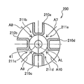
- FIG. 2 is a cross-sectional view of the suction casing along the line AA in FIG. 1. It is sectional drawing corresponding to FIG. 3 of the suction casing as a comparative example.
- FIG. 1 is a cross-sectional view showing a schematic configuration of a multistage submersible pump 20 as an embodiment of the present invention.
- the multistage submersible pump 20 (hereinafter also simply referred to as pump 20) is a submersible pump for deep wells that is installed so that the whole is submerged in the well water.
- the use of the pump 20 is not limited, and the pump 20 can be any multistage submersible pump that handles liquid.
- the number of stages can be any number of 2 or more.
- the pump 20 includes a motor 30, a shaft 40, a suction casing 100, and intermediate casings 50, 60, and 70 connected in multiple stages.
- the shaft 40 extends in the longitudinal direction inside the pump 20 and has an axis AL.
- the shaft 40 is connected to the motor 30 via a coupling 41.
- the suction casing 100 is arranged coaxially with the axis AL.
- the suction casing 100 includes a suction casing main body 110 and flange portions 120 and 130.
- the suction casing 100 is formed with a suction port 111 (in this embodiment, four suction ports 111a to 111d are formed as will be described later, but here they are collectively referred to as the suction port 111). Yes.
- One end side of the suction casing 100 in the axis line AL direction is fixed to the motor 30 by a bolt 125, and the other end side is fixed to the intermediate casing 50 by a bolt 135.
- the intermediate casings 50, 60, and 70 are connected in multiple stages in this order along the axis AL as viewed from the motor 30 side.
- Impellers 51, 61, and 71 are accommodated in the intermediate casings 50, 60, and 70, respectively.
- the impellers 51, 61 and 71 are fixed around the shaft 40.
- guide vanes 52, 62, and 72 are provided inside the intermediate casings 50, 60, and 70 following the impellers 51, 61, and 71, respectively.
- the water flowing in from the suction port 111 is sent to the subsequent stage while being sequentially boosted in each stage, and the discharge casing (not illustrated) connected to the subsequent stage of the intermediate casing (not illustrated) in the final stage. Discharged from.
- FIG. 2 is a perspective view of the suction casing 100.
- FIG. 3 is a cross-sectional view of the suction casing 100 along the line AA of FIG. 1 orthogonal to the axis AL.
- the suction casing 100 includes four suction casing bodies 110a to 110d in this embodiment. These suction casing bodies 110a to 110d extend along the axis AL as shown in FIG. Further, as shown in FIG. 3, the suction casing bodies 110a to 110d are arranged at intervals in the circumferential direction around the axis AL.
- the suction casing bodies 110a to 110d have the same shape, and the cross-sectional shape is formed in an L shape. However, the shapes of the suction casing bodies 110a to 110d can be arbitrarily set.
- the suction casing bodies 110a to 110d are arranged so as to be rotationally symmetric about the axis AL.
- suction ports 111a to 111d are formed along the circumferential direction by a gap between adjacent suction casing bodies among these suction casing bodies 110a to 110d.
- the suction casing bodies 110a to 110d having the same shape are arranged so as to be rotationally symmetric about the axis AL, so that the suction ports 111a to 111d are also rotationally symmetric about the axis AL.
- the suction ports 111a to 111d are formed so that the water inflow directions A2 to A5 in the suction ports 111a to 111d are different from the direction toward the axis AL. Since the suction ports 111a to 111d are arranged so as to be rotationally symmetric about the axis AL, the water inflow directions A2 to A5 are also rotationally symmetric about the axis AL (90 degrees in this embodiment). Rotational symmetry).
- the swirling flow indicated by the arrow A6 can be generated by the water flowing from the suction ports 111a to 111d. That is, the water flowing in from the suction ports 111a to 111d flows along the axis AL while turning around the axis AL, and flows into the first-stage intermediate casing 50. For this reason, pre-swirl can be caused in the water flowing into the first-stage intermediate casing 50 without adding a member such as a current plate. As a result, in all stages including the first stage, the flowing water can be swirled. Therefore, the efficiency of a multistage submersible pump provided with a turning design impeller can be improved.
- the suction ports 111a to 111d are formed so that the inflow directions A2 to A5 are rotationally symmetric about the axis AL, so that a more uniform pre-turn can be generated. .
- the inflow directions A2 to A5 can be arbitrarily set such that the inflow direction of water at one of the suction ports 111a to 111d is rotated by a predetermined angle about the axis AL. . That is, the inflow direction of each suction port can be arbitrarily set so that the flow direction of water flowing from the suction port does not cancel the swirl flow.
- the number of suction ports is not limited to four and can be any number of two or more. In other words, the number of suction casing bodies can be any number of three or more.
- the inner surface of the suction casing body (the inner surface forming the flow path) can be of any shape, for example, an arc shape (for example, the axis AL) in order to suppress sudden changes in the direction of water flow as much as possible. May be formed in a shape of a part of a circle centered at.
- the suction casing 100 includes flange portions 120 and 130.
- the flange portions 120 and 130 are formed at both ends of the suction casing bodies 110a to 110d in the direction of the axis AL, and connect the suction casing bodies 110a to 110d in the circumferential direction.
- the flange 120 is formed at the end of the suction casing bodies 110a to 110d on the motor 30 side.
- a plurality of bolt holes 121 are formed in the flange portion 120 in the circumferential direction. Using the bolt hole 121, the motor 30 and the suction casing 100 can be fixed by the bolt 125 as described above.
- the flange portion 130 is formed at the end of the suction casing bodies 110a to 110d on the intermediate casing 50 side.
- the flange portion 130 includes a first large-diameter portion 131 adjacent to the suction casing bodies 110a to 110d, a second large-diameter portion 133 adjacent to the intermediate casing 50, the first large-diameter portion 131, and the second large-diameter portion.
- a small-diameter portion 132 between the small-diameter portion 133.
- a plurality of bolt holes 134 are formed in the second large diameter portion 133 in the circumferential direction. The bolt hole 134 is formed radially outside the outer peripheral surface of the small diameter portion 132.
- the suction casing 100 and the intermediate casing 50 can be fixed by the bolt 135 as described above. Further, since the small diameter portion 132 is formed, the insertion of the bolting tool and the movable region are ensured satisfactorily. Therefore, the suction casing bodies 110a to 110d are formed on the plane orthogonal to the axis AL. The bolt 135 can be easily tightened.
- notches 122 and 123 are formed in the flange portion 120. These notches 122 and 123 can be used as accommodation spaces for power cables connected to the motor 30.
- FIG. 4 is a cross-sectional view corresponding to FIG. 3 of a suction casing 200 as a comparative example.
- the suction casing 200 includes four substantially U-shaped suction casing bodies 210a to 210d, and suction ports 211a to 211d are formed by gaps therebetween.
- the inflow directions A7 to A10 of water at the suction ports 211a to 211d are directions toward the axis AL.
- the swirling flow as shown by the arrow A6 in FIG. 3 does not occur, and the water flowing in from the suction ports 211a to 211d goes straight to the intermediate casing 50 along the axis AL. . Therefore, when the suction casing 200 is used for a multistage submersible pump including a swirl design impeller, the efficiency at the first stage is reduced as compared with the case where the suction casing 100 of the present embodiment is used.
Landscapes
- Engineering & Computer Science (AREA)
- Mechanical Engineering (AREA)
- General Engineering & Computer Science (AREA)
- Structures Of Non-Positive Displacement Pumps (AREA)
Abstract
Description
図1は、本発明の一実施形態としての多段水中ポンプ20の概略構成を示す断面図である。多段水中ポンプ20(以下、単にポンプ20とも呼ぶ)は、本実施例では、その全体が井戸水中に水没するように設置される深井戸用水中ポンプである。ただし、ポンプ20の用途は限定されるものではなく、ポンプ20は、液体を扱う任意の多段水中ポンプとすることができる。また、段数は、2以上の任意の数とすることができる。
30…モータ
40…シャフト
41…カップリング
50,60,70…中間ケーシング
51,61,71…羽根車
52,62,72…ガイドベーン
100…吸込ケーシング
110,110a,110b,110c,110d…吸込ケーシング本体
111,111a,111b,111c,111d…吸込口
120,130…フランジ部
121,134…ボルト穴
122,123…切欠
125,135…ボルト
131…第1の大径部
132…小径部
133…第2の大径部
AL…軸線
Claims (5)
- 液体を扱う多段水中ポンプ用の吸込ケーシングであって、
軸線に沿って延在するとともに前記軸線を中心として周方向に間隔を隔てて配置される複数のケーシング本体を備え、
前記複数のケーシング本体同士の隙間によって、前記周方向に沿って複数の吸込口が形成され、
前記複数の吸込口は、前記軸線と直交する断面において、
前記複数の吸込口の各々における前記液体の流入方向が前記軸線に向かう方向とは異なる方向となり、
前記複数の吸込口の各々における前記液体の流入方向が、前記複数の吸込口のうちの1つの吸込口における前記液体の流入方向を、前記軸線を中心として所定角度回転させた方向となるように形成された
吸込ケーシング。 - 液体を扱う多段水中ポンプ用の吸込ケーシングであって、
軸線に沿って延在するとともに前記軸線を中心として周方向に間隔を隔てて配置される複数のケーシング本体を備え、
前記複数のケーシング本体同士の隙間によって、前記周方向に沿って複数の吸込口が形成され、
前記複数の吸込口は、該複数の吸込口から流入する前記液体が前記軸線と直交する断面において該軸線に向かう方向とは異なる方向に流入して、旋回流を生じさせるように形成されている
吸込ケーシング。 - 請求項1または請求項2に記載の吸込ケーシングであって、
前記複数の吸込口は、該複数の吸込口の各々における前記液体の流入方向が、前記軸線を中心とした回転対称となるように形成された
吸込ケーシング。 - 請求項1ないし請求項3のいずれか一項に記載の吸込ケーシングであって、
さらに、前記軸線方向における前記複数のケーシング本体の一端または両端に、該複数のケーシング本体同士を周方向に連結するフランジ部を備える
吸込ケーシング。 - 液体を扱う多段水中ポンプであって、
請求項1ないし請求項4のいずれか一項に記載の吸込ケーシングと、
前記吸込ケーシングの、前記軸線方向における一方側に配置されるモータと、
前記吸込ケーシングの他方側に多段に配置される中間ケーシングであって、前記モータによって回転駆動される羽根車が各段に収容される中間ケーシングと
を備える多段水中ポンプ。
Priority Applications (2)
| Application Number | Priority Date | Filing Date | Title |
|---|---|---|---|
| BR112018016288-4A BR112018016288B1 (pt) | 2016-02-10 | 2017-02-06 | Invólucro de sucção de bomba submersível multiestágio e bomba submersível multiestágio |
| CN201780010440.7A CN108603507B (zh) | 2016-02-10 | 2017-02-06 | 多段潜水泵用的吸入外壳、以及多段潜水泵 |
Applications Claiming Priority (2)
| Application Number | Priority Date | Filing Date | Title |
|---|---|---|---|
| JP2016023674A JP6624962B2 (ja) | 2016-02-10 | 2016-02-10 | 多段水中ポンプ用の吸込ケーシング、および、多段水中ポンプ |
| JP2016-023674 | 2016-02-10 |
Publications (1)
| Publication Number | Publication Date |
|---|---|
| WO2017138472A1 true WO2017138472A1 (ja) | 2017-08-17 |
Family
ID=59563311
Family Applications (1)
| Application Number | Title | Priority Date | Filing Date |
|---|---|---|---|
| PCT/JP2017/004148 Ceased WO2017138472A1 (ja) | 2016-02-10 | 2017-02-06 | 多段水中ポンプ用の吸込ケーシング、および、多段水中ポンプ |
Country Status (5)
| Country | Link |
|---|---|
| JP (1) | JP6624962B2 (ja) |
| CN (1) | CN108603507B (ja) |
| BR (1) | BR112018016288B1 (ja) |
| TW (1) | TWI710704B (ja) |
| WO (1) | WO2017138472A1 (ja) |
Cited By (1)
| Publication number | Priority date | Publication date | Assignee | Title |
|---|---|---|---|---|
| WO2023095638A1 (ja) * | 2021-11-29 | 2023-06-01 | 株式会社モリタ | 遠心ポンプ、遠心ポンプ装置、及び消防自動車 |
Families Citing this family (1)
| Publication number | Priority date | Publication date | Assignee | Title |
|---|---|---|---|---|
| CN109441841B (zh) * | 2018-11-17 | 2024-05-07 | 广东瑞荣泵业有限公司 | 空间扭曲塑料叶轮式井用潜水泵 |
Citations (2)
| Publication number | Priority date | Publication date | Assignee | Title |
|---|---|---|---|---|
| JPS5424103U (ja) * | 1977-07-21 | 1979-02-16 | ||
| JP2007247414A (ja) * | 2006-03-13 | 2007-09-27 | Mitsubishi Heavy Ind Ltd | ポンプ |
Family Cites Families (6)
| Publication number | Priority date | Publication date | Assignee | Title |
|---|---|---|---|---|
| JPS5134008Y2 (ja) * | 1973-10-16 | 1976-08-23 | ||
| CN86204176U (zh) * | 1986-06-16 | 1987-06-10 | 中国石化销售公司山西省石油公司 | 有诱导轮的多级卧式离心泵 |
| ITVI20020095A1 (it) * | 2002-05-15 | 2003-11-17 | Vertical Srl | Pompa multistadio particolarmente di tipo ad immersione |
| CN103163620B (zh) * | 2011-12-16 | 2015-01-07 | 佳能企业股份有限公司 | 镜头机构 |
| WO2015097851A1 (ja) * | 2013-12-27 | 2015-07-02 | 株式会社イワキ | マグネットポンプ |
| KR20150032686A (ko) * | 2015-03-09 | 2015-03-27 | 재단법인 중소조선연구원 | 원심펌프의 임펠러 흡입 안내장치 |
-
2016
- 2016-02-10 JP JP2016023674A patent/JP6624962B2/ja active Active
-
2017
- 2017-02-06 WO PCT/JP2017/004148 patent/WO2017138472A1/ja not_active Ceased
- 2017-02-06 CN CN201780010440.7A patent/CN108603507B/zh active Active
- 2017-02-06 BR BR112018016288-4A patent/BR112018016288B1/pt active IP Right Grant
- 2017-02-08 TW TW106104070A patent/TWI710704B/zh active
Patent Citations (2)
| Publication number | Priority date | Publication date | Assignee | Title |
|---|---|---|---|---|
| JPS5424103U (ja) * | 1977-07-21 | 1979-02-16 | ||
| JP2007247414A (ja) * | 2006-03-13 | 2007-09-27 | Mitsubishi Heavy Ind Ltd | ポンプ |
Cited By (1)
| Publication number | Priority date | Publication date | Assignee | Title |
|---|---|---|---|---|
| WO2023095638A1 (ja) * | 2021-11-29 | 2023-06-01 | 株式会社モリタ | 遠心ポンプ、遠心ポンプ装置、及び消防自動車 |
Also Published As
| Publication number | Publication date |
|---|---|
| BR112018016288A2 (ja) | 2018-12-26 |
| CN108603507B (zh) | 2020-02-07 |
| TW201730436A (zh) | 2017-09-01 |
| BR112018016288B1 (pt) | 2023-12-26 |
| TWI710704B (zh) | 2020-11-21 |
| CN108603507A (zh) | 2018-09-28 |
| JP2017141735A (ja) | 2017-08-17 |
| JP6624962B2 (ja) | 2019-12-25 |
Similar Documents
| Publication | Publication Date | Title |
|---|---|---|
| US8087901B2 (en) | Fluid channeling device for back-to-back compressors | |
| JP6336134B2 (ja) | 遠心圧縮機のケーシング、及び、遠心圧縮機 | |
| EP3088739B1 (en) | Magnetic pump | |
| KR101521904B1 (ko) | 축류펌프 | |
| JP6712159B2 (ja) | ディフューザ、及び多段ポンプ装置 | |
| WO2017138472A1 (ja) | 多段水中ポンプ用の吸込ケーシング、および、多段水中ポンプ | |
| EP3341613B1 (en) | Centrifugal pump with serrated impeller | |
| JP2018523055A (ja) | 遠心ポンプ | |
| CA2938192C (en) | Horizontal pumping system with primary stage assembly and separate npsh stage assembly | |
| JP3924233B2 (ja) | ターボポンプのディフューザ | |
| RU2769329C2 (ru) | Многоступенчатый насос со свойствами улучшенной балансировки напора | |
| JP2010236401A (ja) | 遠心形流体機械 | |
| JP5074218B2 (ja) | 多段ポンプ | |
| JP2018091317A (ja) | 多段ポンプ | |
| US10465687B2 (en) | Device for conditioning flow of working fluids | |
| JP2013019346A (ja) | 水中ポンプ | |
| JP6626900B2 (ja) | 遠心圧縮機 | |
| JP2016148306A (ja) | ガイド体、及びポンプ装置 | |
| JP6071197B2 (ja) | 多方向吸込ケーシングおよび遠心式流体機械 | |
| JP2016035228A (ja) | ポンプ | |
| KR20110093458A (ko) | 유입공이 형성된 임펠러를 구비한 터보 압축기 | |
| CN106438479A (zh) | 一种多级水泵泵盖 | |
| JP2017214838A (ja) | タービンポンプ及びポンプ用ケーシング | |
| WO2017073499A1 (ja) | ターボ機械 |
Legal Events
| Date | Code | Title | Description |
|---|---|---|---|
| 121 | Ep: the epo has been informed by wipo that ep was designated in this application |
Ref document number: 17750195 Country of ref document: EP Kind code of ref document: A1 |
|
| NENP | Non-entry into the national phase |
Ref country code: DE |
|
| REG | Reference to national code |
Ref country code: BR Ref legal event code: B01A Ref document number: 112018016288 Country of ref document: BR |
|
| ENP | Entry into the national phase |
Ref document number: 112018016288 Country of ref document: BR Kind code of ref document: A2 Effective date: 20180809 |
|
| 122 | Ep: pct application non-entry in european phase |
Ref document number: 17750195 Country of ref document: EP Kind code of ref document: A1 |