WO2017138330A1 - 発熱体制御装置、エンジン制御システム - Google Patents
発熱体制御装置、エンジン制御システム Download PDFInfo
- Publication number
- WO2017138330A1 WO2017138330A1 PCT/JP2017/001986 JP2017001986W WO2017138330A1 WO 2017138330 A1 WO2017138330 A1 WO 2017138330A1 JP 2017001986 W JP2017001986 W JP 2017001986W WO 2017138330 A1 WO2017138330 A1 WO 2017138330A1
- Authority
- WO
- WIPO (PCT)
- Prior art keywords
- resistance value
- heating element
- temperature
- engine
- glow plug
- Prior art date
- Legal status (The legal status is an assumption and is not a legal conclusion. Google has not performed a legal analysis and makes no representation as to the accuracy of the status listed.)
- Ceased
Links
Images

Classifications
-
- F—MECHANICAL ENGINEERING; LIGHTING; HEATING; WEAPONS; BLASTING
- F02—COMBUSTION ENGINES; HOT-GAS OR COMBUSTION-PRODUCT ENGINE PLANTS
- F02P—IGNITION, OTHER THAN COMPRESSION IGNITION, FOR INTERNAL-COMBUSTION ENGINES; TESTING OF IGNITION TIMING IN COMPRESSION-IGNITION ENGINES
- F02P19/00—Incandescent ignition, e.g. during starting of internal combustion engines; Combination of incandescent and spark ignition
- F02P19/02—Incandescent ignition, e.g. during starting of internal combustion engines; Combination of incandescent and spark ignition electric, e.g. layout of circuits of apparatus having glowing plugs
-
- B—PERFORMING OPERATIONS; TRANSPORTING
- B60—VEHICLES IN GENERAL
- B60H—ARRANGEMENTS OF HEATING, COOLING, VENTILATING OR OTHER AIR-TREATING DEVICES SPECIALLY ADAPTED FOR PASSENGER OR GOODS SPACES OF VEHICLES
- B60H1/00—Heating, cooling or ventilating devices
- B60H1/22—Heating, cooling or ventilating devices the heat source being other than the propulsion plant
- B60H1/2215—Heating, cooling or ventilating devices the heat source being other than the propulsion plant the heat being derived from electric heaters
- B60H1/2218—Heating, cooling or ventilating devices the heat source being other than the propulsion plant the heat being derived from electric heaters controlling the operation of electric heaters
-
- F—MECHANICAL ENGINEERING; LIGHTING; HEATING; WEAPONS; BLASTING
- F02—COMBUSTION ENGINES; HOT-GAS OR COMBUSTION-PRODUCT ENGINE PLANTS
- F02D—CONTROLLING COMBUSTION ENGINES
- F02D41/00—Electrical control of supply of combustible mixture or its constituents
- F02D41/02—Circuit arrangements for generating control signals
- F02D41/04—Introducing corrections for particular operating conditions
- F02D41/06—Introducing corrections for particular operating conditions for engine starting or warming up
- F02D41/062—Introducing corrections for particular operating conditions for engine starting or warming up for starting
-
- F—MECHANICAL ENGINEERING; LIGHTING; HEATING; WEAPONS; BLASTING
- F02—COMBUSTION ENGINES; HOT-GAS OR COMBUSTION-PRODUCT ENGINE PLANTS
- F02M—SUPPLYING COMBUSTION ENGINES IN GENERAL WITH COMBUSTIBLE MIXTURES OR CONSTITUENTS THEREOF
- F02M31/00—Apparatus for thermally treating combustion-air, fuel, or fuel-air mixture
- F02M31/02—Apparatus for thermally treating combustion-air, fuel, or fuel-air mixture for heating
- F02M31/12—Apparatus for thermally treating combustion-air, fuel, or fuel-air mixture for heating electrically
- F02M31/125—Fuel
-
- F—MECHANICAL ENGINEERING; LIGHTING; HEATING; WEAPONS; BLASTING
- F02—COMBUSTION ENGINES; HOT-GAS OR COMBUSTION-PRODUCT ENGINE PLANTS
- F02M—SUPPLYING COMBUSTION ENGINES IN GENERAL WITH COMBUSTIBLE MIXTURES OR CONSTITUENTS THEREOF
- F02M31/00—Apparatus for thermally treating combustion-air, fuel, or fuel-air mixture
- F02M31/02—Apparatus for thermally treating combustion-air, fuel, or fuel-air mixture for heating
- F02M31/12—Apparatus for thermally treating combustion-air, fuel, or fuel-air mixture for heating electrically
- F02M31/13—Combustion air
-
- F—MECHANICAL ENGINEERING; LIGHTING; HEATING; WEAPONS; BLASTING
- F02—COMBUSTION ENGINES; HOT-GAS OR COMBUSTION-PRODUCT ENGINE PLANTS
- F02N—STARTING OF COMBUSTION ENGINES; STARTING AIDS FOR SUCH ENGINES, NOT OTHERWISE PROVIDED FOR
- F02N19/00—Starting aids for combustion engines, not otherwise provided for
- F02N19/02—Aiding engine start by thermal means, e.g. using lighted wicks
-
- F—MECHANICAL ENGINEERING; LIGHTING; HEATING; WEAPONS; BLASTING
- F02—COMBUSTION ENGINES; HOT-GAS OR COMBUSTION-PRODUCT ENGINE PLANTS
- F02N—STARTING OF COMBUSTION ENGINES; STARTING AIDS FOR SUCH ENGINES, NOT OTHERWISE PROVIDED FOR
- F02N19/00—Starting aids for combustion engines, not otherwise provided for
- F02N19/02—Aiding engine start by thermal means, e.g. using lighted wicks
- F02N19/04—Aiding engine start by thermal means, e.g. using lighted wicks by heating of fluids used in engines
-
- F—MECHANICAL ENGINEERING; LIGHTING; HEATING; WEAPONS; BLASTING
- F02—COMBUSTION ENGINES; HOT-GAS OR COMBUSTION-PRODUCT ENGINE PLANTS
- F02N—STARTING OF COMBUSTION ENGINES; STARTING AIDS FOR SUCH ENGINES, NOT OTHERWISE PROVIDED FOR
- F02N19/00—Starting aids for combustion engines, not otherwise provided for
- F02N19/02—Aiding engine start by thermal means, e.g. using lighted wicks
- F02N19/04—Aiding engine start by thermal means, e.g. using lighted wicks by heating of fluids used in engines
- F02N19/10—Aiding engine start by thermal means, e.g. using lighted wicks by heating of fluids used in engines by heating of engine coolants
-
- H—ELECTRICITY
- H05—ELECTRIC TECHNIQUES NOT OTHERWISE PROVIDED FOR
- H05B—ELECTRIC HEATING; ELECTRIC LIGHT SOURCES NOT OTHERWISE PROVIDED FOR; CIRCUIT ARRANGEMENTS FOR ELECTRIC LIGHT SOURCES, IN GENERAL
- H05B1/00—Details of electric heating devices
- H05B1/02—Automatic switching arrangements specially adapted to apparatus ; Control of heating devices
- H05B1/0227—Applications
- H05B1/023—Industrial applications
- H05B1/0236—Industrial applications for vehicles
-
- B—PERFORMING OPERATIONS; TRANSPORTING
- B60—VEHICLES IN GENERAL
- B60H—ARRANGEMENTS OF HEATING, COOLING, VENTILATING OR OTHER AIR-TREATING DEVICES SPECIALLY ADAPTED FOR PASSENGER OR GOODS SPACES OF VEHICLES
- B60H1/00—Heating, cooling or ventilating devices
- B60H1/22—Heating, cooling or ventilating devices the heat source being other than the propulsion plant
- B60H2001/2228—Heating, cooling or ventilating devices the heat source being other than the propulsion plant controlling the operation of heaters
Definitions
- the present disclosure relates to a heating element control device that controls the temperature of a heating element provided in an engine, and an engine control system.
- an engine is provided with a heating element that maintains each part at a predetermined temperature for reasons such as ensuring combustion performance during cold start.
- the heating element is connected to a power source via a control device, and the temperature is controlled to be constant by the control device.
- Patent Document 1 discloses temperature control of a glow plug which is an example of a heating element.
- the control unit acquires the resistance value of the newly replaced glow plug at a predetermined temperature, and uses this resistance value as the target resistance. Value.
- the control unit acquires a target power amount necessary for causing the glow plug to reach the target temperature.
- a control part inputs the acquired target electric energy into a glow plug, and controls a glow plug to become target temperature.
- the engine includes a plurality of heating elements for each cylinder, but the heating elements have individual differences and their resistance values vary.
- the heating element deteriorates with aging and continues to change its resistance value. If the resistance value changes over time, even if the resistance value of the heating element is controlled to the set value, the temperature of the heating element may change and it may not be possible to ensure the combustion performance at the time of cold engine start . Therefore, as described in Patent Document 1, after replacing the heating element, the resistance value of the heating element is acquired only once and the heating element is controlled by the acquired resistance value. In some cases, the temperature control of each heating element cannot be performed properly unless the heating element is replaced and the resistance value is acquired.
- the present disclosure has been made in view of the above problems, and provides a heating element control device or an engine control system that can automatically reduce variations in temperature of heating elements without requiring a special operation. For the purpose.
- a heating element control device that controls the temperature of a heating element provided in an engine, the temperature control unit controlling the temperature of the heating element to a target temperature by supplying constant power to the heating element.
- a resistance value acquisition unit that acquires a resistance value of the heating element at the target temperature as a target resistance value, and controls the resistance value of the heating element so that the resistance value of the heating element is maintained at the target resistance value
- a resistance control unit configured to supply the constant power to the heating element before the engine is started after the engine start request is made, and the resistance control unit The unit maintains the resistance value of the heating element at the target resistance value obtained by supplying the constant power to the heating element before starting the engine.
- the temperature control unit supplies constant power to the heating element, so that the temperature of the heating element becomes a steady state at a predetermined temperature that correlates with the amount of supplied power.
- the resistance value of the heating element that has changed with the temperature converges to a value corresponding to each variation.
- the temperature of the heating element converges to a temperature corresponding to the physical properties. That is, each resistance value of the heating element obtained in this state is obtained in a state where the temperatures of the heating elements are matched.
- the resistance control unit individually controls the resistance value of the heating element so that the resistance value of the heating element is maintained at the resistance value in the steady state. Therefore, even when the resistance value of the heating element changes due to deterioration over time, the temperature of the heating element can be maintained within a predetermined range.
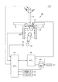
- FIG. 1 is a configuration diagram showing an overall outline of an engine control system.
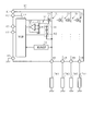
- FIG. 2 is a schematic diagram showing the circuit configuration of the GCU.
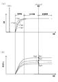
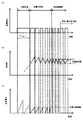
- FIG. 3 is a diagram for explaining the control for the glow plug,
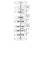
- FIG. 4 is a flowchart showing control on the glow plug,
- FIG. 5 is an operation chart showing the change of each value in the control for the glow plug,
- FIG. 6 is an operation chart for explaining the operation of the GCU according to the second embodiment.
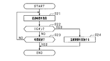
- FIG. 7 is a flowchart showing processing performed in a predetermined period after IG OFF,
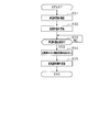
- FIG. 8 is a diagram illustrating the process performed in step S24.
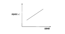
- FIG. 9 is a diagram illustrating the setting of the temperature raising time Tim_r performed in step S31.
- FIG. 10 is an operation chart showing the timing at which the GCU according to the third embodiment performs constant power control and resistance control.
- FIG. 1 is a configuration diagram showing an overall outline of an engine control system in the present embodiment.
- the engine control system 100 includes an engine 10, a battery 21, a glow control unit 30 (hereinafter also referred to as GCU), and an ECU (Electronic Control Unit) 50.
- GCU glow control unit 30
- ECU Electronic Control Unit
- the engine 10 is a well-known internal combustion engine that performs an internal combustion motion.
- the engine 10 is described as a four-cylinder engine.
- an intake valve 11 and an exhaust valve 12 are provided at an intake port and an exhaust port of an engine 10, respectively.
- the tip of a fuel injection valve 16 protrudes, and fuel is supplied by the fuel injection valve 16. Then, the fuel self-ignites with the compression in the combustion chamber 14 and combustion is performed. Further, air is introduced into the combustion chamber 14 from the intake pipe (intake passage) 13 by the opening operation of the intake valve 11, and exhaust gas after combustion is discharged to the exhaust pipe (exhaust passage) 15 by the opening operation of the exhaust valve 12. .
- a glow plug 17 that functions as a heating element is disposed in the combustion chamber 14 of the engine 10.
- the glow plug 17 is, for example, a ceramic glow plug having a ceramic heater.
- the glow plug 17 has a tip projecting from the combustion chamber 14 and heats the gas in the combustion chamber 14 by heat generation, thereby improving the ignitability of the fuel of the engine 10.
- each cylinder is provided with four glow plugs, and when the glow plugs are distinguished from each other, reference numerals 17 # 1, 17 # 2, 17 # 3, and 17 # 4 are attached.
- the term “temperature of the glow plug 17” means the temperature of the heater in the glow plug 17
- the term “resistance of the glow plug 17” means the resistance of the heater.
- the GCU 30 controls power supply to the glow plug 17.
- the GCU 30 is connected to the glow plug 17 and the battery 21 respectively, and controls energization from the battery 21 to the glow plug 17.
- the detailed configuration of the GCU 30 will be described later.
- the battery 21 functions as a power source and supplies power to each part of the engine control system 100.
- the battery 21 is, for example, a lead storage battery that supplies DC power, and supplies power to a load (not shown) in addition to the illustrated GCU 30 and ECU 50.
- a main relay 26 is interposed between the battery 21 and the ECU 50 and GCU 30.
- the main relay 26 also functions as a switch that opens and closes a path that connects the battery 21 to the ECU 50 and the GCU 30.
- the main relay 26 is composed of, for example, a switch that connects paths and a solenoid that operates this switch.
- the ECU 50 controls the driving of the engine control system 100 in an integrated manner.
- the ECU 50 is configured mainly with a microcomputer including a CPU, a ROM, a RAM, and the like, for example. And various control of the engine 10 is implemented according to an engine driving
- IG ignition
- the ECU 50 calculates a command input SI based on the engine operating state for each power supply to the glow plug 17 and outputs the command input SI to the GCU 30.
- the engine operating state include engine rotation speed, engine water temperature, outside air temperature, fuel injection amount, and the like.
- FIG. 2 is a schematic diagram showing a circuit configuration of the GCU 30.
- the GCU 30 is connected to the battery 21 through the battery terminal 41 and the control system power supply terminal 42, and receives power from the battery 21 through the battery terminal 41 and the control system power supply terminal 42.
- the control system power supply terminal 42 is connected to the battery 21 via the main relay 26.
- the GCU 30 is connected to the ECU 50 via the communication terminals 43 and 44, and communicates with the ECU 50 via the communication terminals 43 and 44.
- the GCU 30 is connected to the glow plug 17 via the output terminal 46.
- the GCU 30 is connected to the ground via the ground terminal 45.
- the GCU 30 includes a switching unit 31, a voltage detection unit 32, a current detection unit 34, and a control unit 37 as its functions.
- the GCU 30 is configured by a one-chip microcomputer, and the above-described switching unit 31, voltage detection unit 32, current detection unit 34, and control unit 37 are configured as functional blocks of this one-chip microcomputer.
- the GCU 30 is not limited to one configured by a microcomputer, and the above-described units may be configured by hardware circuits.
- the GCU 30 includes a switching unit 31, a voltage detection unit 32, and a current detection unit 34 for each of the glow plugs 17 # 1 to 17 # 4.
- the switching unit 31, the voltage detection unit 32, and the current detection unit 34 corresponding to the glow plug 17 # 1 are illustrated, and the configurations corresponding to the other glow plugs 17 # 2 to 17 # 4 are illustrated. Is omitted.
- the switching unit 31 controls the power supply of the glow plug 17 by an on / off operation.
- the switching unit 31 includes a switch element TR made of, for example, a MOS transistor.
- the drain of the switch element TR is connected to the battery 21 via the battery terminal 41, and the source thereof is connected to the glow plug 17 via the output terminal 46.
- the gate of the switch element TR is connected to the output terminal of the control unit 37.
- the voltage detector 32 detects the voltage value Vg of the glow plug 17 and outputs the detected voltage value Vg to the controller 37.
- the detection terminal of the voltage detection unit 32 is connected to a node connecting the source of the switching unit 31 and the output terminal 46, and the output terminal is connected to the input terminal of the control unit 37.
- the current detector 34 detects the current value Ig of the glow plug 17.
- the current detection unit 34 has different parts so as to detect the current when the battery 21 is energized (when the switching unit 31 is on) and when the battery 21 is not energized (when the switching unit 31 is off). (The energization current detection unit 35 and the non-energization current drive unit 36).
- the energization current detection unit 35 detects the current value of the glow plug 17 when the battery 21 is energized.
- the energization current detection unit 35 includes a sense resistor R1 and an operational amplifier OP that calculates values at both ends of the sense resistor R1.
- One end of the sense resistor R1 is connected to the sense terminal of the switch element TR.
- the operational amplifier OP outputs an output corresponding to the voltage value generated in the sense resistor R ⁇ b> 1 to the control unit 37 when the battery 21 is energized.
- control unit 37 Since this output changes depending on the current value of the glow plug 17, the control unit 37 obtains applied power based on the output from the energization current detection unit 35 and the output from the voltage detection unit 32, and By obtaining the resistance value of the heating element of the plug, the current value of the glow plug 17 can be controlled.
- the non-energized current drive unit 36 includes a resistor R2. One end of the resistor R2 is connected to a constant current source, and the other end of the resistor R2 is connected to a node connecting the source of the switch element TR and the output terminal 46. Has been.
- the control unit 37 causes the current from the constant current source to flow to the glow plug 17 from the non-energized current driving unit 36 when the switch element TR is off. Since the value of the current from the constant current source is constant, the control unit 37 determines the voltage value during non-energization generated in the glow plug 17 detected by the voltage detection unit 32, the drive current from the constant current source, Thus, the resistance value of the heating element can be detected.
- the resistance R2 of the non-energized current drive unit 36 be a low value, similarly to the resistance value Rg of the glow plug 17.
- connecting the non-energized current drive unit 36 to a constant current source is merely an example.
- the non-energized current driving unit 36 is connected only to the constant voltage source, and controls the current value according to the voltage dividing ratio between the resistance R2 and the resistance value Rg of the glow plug 17 via an operational amplifier or the like. It may be output to the unit 37.
- the non-energizing current drive unit 36 is always energized, and the control unit 37 adds a constant current component to the current value obtained by the energizing current detection unit 35 as the energizing current when the switch element TR is turned on. May be controlled.
- the control unit 37 can suppress an error due to a timing difference between the current output and the voltage detection in detecting the resistance value of the heating element when the glow plug 17 is energized and de-energized.
- the control unit 37 and the non-energized current drive unit 36 may not be electrically connected.
- control unit 37 detects the resistance value Rg of the glow plug 17 by dividing the voltage acquired by the voltage detection unit 32 by the current acquired by the current detection unit 34 and the non-energized current drive unit 36. In this embodiment, the controller 37 detects the resistance value Rg using the current Ig detected by the energization current detector 35 when the battery 21 is energized. In addition, the control unit 37 detects the resistance value Rg using the current Ig (current value during non-energization) detected according to the driving of the non-energized current drive unit 36 when the battery 21 is not energized. Therefore, in this embodiment, the control unit 37 also functions as a resistance detection unit.
- the control unit 37 controls the driving of the switching unit 31.
- the control unit 37 is mainly configured by a microcomputer (hereinafter referred to as a microcomputer) composed of, for example, a well-known CPU, ROM, RAM, and the like.
- the control unit 37 receives a command input SI from the ECU 50 via the communication terminal 43 and outputs a gate signal for operating each switching unit 31.
- the glow plugs 17 # 1 to 17 # 4 are energized by this gate signal so that the energization timing arrives every predetermined period (for example, 30 msec).
- the control unit 37 outputs a diagnosis result to the ECU 50 via the communication terminal 44 when an abnormality is detected during abnormality diagnosis of the glow plug 17.
- FIGS. 3A and 3B temperature control of the glow plug 17 will be described with reference to FIGS. 3A and 3B.
- the temperature change for the four glow plugs 17 # 1 to 17 # 4 in which the resistance value varies is shown in FIG. 3A, and the resistance value change is shown in FIG. 3B.
- the GCU 30 controls the temperature of the glow plug 17 at a constant temperature (resistance value control) every time the IG switch 25 is turned on (hereinafter also referred to as IG on).
- the constant power control is performed after the rapid temperature raising operation for driving at the maximum power every time the IG is turned on in order to keep the temperature of the glow plug 17 at the target temperature in the steady state.
- This constant power control is performed in a period in which there is little disturbance affecting the glow plug temperature, such as until the start (cranking) of the engine 10 by a starter (not shown) is started.
- Rapid heating is performed by rapidly applying a battery voltage to the glow plug 17 for a certain time so that the temperature of the glow plug 17 increases.
- the rapid temperature increase is performed by open control in which a voltage is applied at a PWM duty drive duty of 100% and the time for temperature increase is set to a predetermined value.
- the constant power control is repeatedly turned on and off so that the energization is turned on at a predetermined constant cycle, and the energization is turned off when the integrated power calculated from the voltage and current reaches a set value. Control. Further, the resistance value when the set integrated power value is reached is obtained.
- the glow plug is set so that the supplied power becomes a constant value. The energization to 17 is controlled. As shown in FIG.
- the constant power control is continued until the temperature of the glow plug 17 reaches a steady state where the temperature is within a predetermined range.
- the temperatures of the glow plugs 17 # 1 to 17 # 4 in the steady state are determined by the specific heat or material of the glow plug 17 because the heat dissipation characteristics of the glow plug 17 are substantially the same.
- the glow plugs 17 # 1 to # 4 Temperature converges to the same temperature.
- the resistance values Rg1 to Rg4 of the glow plug 17 when converged to the steady state vary depending on individual variations, changes with time, and the like.
- each resistance value obtained by constant power control is a resistance targeted for control.
- the resistance value of the glow plug 17 is controlled to be maintained at the resistance value in the steady state during the constant power control.
- the switching unit 31 is turned on / off while detecting the resistance value so that the detected resistance values Rg1, 2, 3, 4 of the glow plug 17 are maintained at these control target values. Control is implemented.
- the resistance values Rg1 to Rg4 are maintained in a certain range for the glow plugs 17 # 1 to 17 # 4, respectively, and the temperature of the glow plug 17 is maintained at a temperature converged by constant power control.
- FIGS. 3A and 3B control for the glow plug 17 shown in FIGS. 3A and 3B will be described with reference to the flowchart shown in FIG.
- the processes shown in and after S12 in FIG. 4 are processes performed by the GCU 30 each time the IG switch 25 is turned on.
- the GCU 30 functions as a temperature control unit by performing the processes of steps S12 to S15, and functions as a resistance value acquiring unit by performing the process of step S16, and performs the process of S17.
- FIGS. 5A to 5C are operation charts showing changes in values in the control of the glow plug 17.
- step S11 it is determined whether IG is on. For example, when the IG switch 25 is operated and the main relay 26 is turned on so that the power from the battery 21 is supplied to the GCU 30, the GCU 30 determines that the IG is on. The GCU 30 determines that a start request for the engine 10 has been generated based on the determination that the IG is on. In step S ⁇ b> 11, the ECU 50 may determine that a start request has been generated when the IG is turned on, and the GCU 30 may determine that a start request has been generated for the engine 10 by transmitting an energization command to the GCU 30.
- step S12 rapid temperature increase is performed.
- the GCU 30 controls the switching unit 31 so that the duty becomes 100%, and the temperature of the glow plug 17 is increased by the application of the battery voltage at this time. Due to this rapid temperature rise, the temperature of the glow plug 17 rises rapidly.
- step S13 the elapse of the temperature raising time Tim_r is determined.
- the temperature increase time Tim_r in step S13 is a time that is predetermined as a time required for the glow plug 17 to reach a predetermined temperature when a battery voltage of 100% is applied, for example. That is, the temperature of the glow plug 17 quickly reaches a predetermined temperature range by performing rapid temperature increase for the temperature increase time Tim_r.
- step S14 When it is determined that the temperature increase time Tim_r has elapsed (step S13: YES), constant power control is performed in step S14. As shown in FIG. 5A, during the period in which the constant power control is performed, the GCU 30 integrates the power during the on period obtained by multiplying the voltage value Vg and the current value Ig detected in the predetermined period. The energization to the glow plug 17 is repeatedly controlled such that the energization is turned off at a predetermined integrated value and the energization is turned on at a constant cycle, so that the integrated power per cycle becomes constant at the predetermined integrated value.
- the glow plug 17 is warmed according to the input electric power, and changes its resistance value Rg as shown in FIG.
- step S15 a change in the resistance value Rg of the glow plug 17 is monitored.
- the GCU 30 monitors the resistance value Rg.
- the GCU 30 monitors the respective resistance values Rg # 1 to # 4 of the glow plugs 17 # 1 to 17 # 4.
- the period during which the resistance value Rg is continuously monitored in step S15 is determined based on whether or not the resistance value Rg at a predetermined timing of the glow plug 17 converges within a certain range (steady state). For example, the GCU 30 stores the resistance value Rg immediately before turning off the power, and determines that the resistance value Rg has converged to a certain range if the difference between the previous and current resistance values Rg is equal to or less than a threshold value. In FIG. 5B, the resistance value Rg has converged within a certain range on the right side in the figure, and the GCU 30 performs convergence determination.
- Convergence determination is performed when the difference between the previous and current resistance values at the start of energization is less than a predetermined value, or the difference between the previous and current constant power control on-time is less than a predetermined value. In this case, it may also be determined that the convergence has occurred when the difference between the previous and current glow plug temperatures separately measured at a predetermined period is equal to or less than a predetermined value. In addition to this, the convergence determination may be performed when the resistance value Rg is continuously within a predetermined number of times.
- the resistance value Rg at this time is acquired as the target resistance value Tg.
- This target resistance value Tg is a target value in resistance value control.
- target resistance values Tg # 1 to Tg # 4 are acquired for each of the glow plugs 17 # 1 to 17 # 4 every time the IG is turned on.
- the target resistance value Tg may be obtained by averaging a plurality of values immediately before the convergence point of the resistance value Rg.
- the acquisition timings of the target resistance values Tg # 1 to Tg # 4 corresponding to the glow plugs 17 # 1 to 17 # 4 in step S16 are the resistance values Rg of all the glow plugs 17 # 1 to 17 # 4 in step S15. Is implemented on the condition that has converged.
- the target resistance values Tg # 1 to Tg # 4 are acquired in step S16. It may be.
- step S17 resistance value control is performed.
- the GCU 30 controls the glow plug 17 so that the resistance value Rg of each of the glow plugs 17 # 1 to 17 # 4 approaches the corresponding target resistance value Tg (# 1 to # 4) acquired in step S16.
- Energization is controlled (FIG. 5A). For example, when the resistance value Rg becomes larger than the target resistance value Tg, the GCU 30 turns off the battery voltage. On the other hand, when the resistance value Rg becomes smaller than the target resistance value Tg by a predetermined value or more, the GCU 30 turns on the battery voltage.
- FIG. 5C the description of the power change in the resistance value control is omitted for convenience.
- Resistance value control is terminated when the engine 10 is turned off (also referred to as IG off) by operating the IG switch 25, and the processing shown in FIG. 4 is terminated.
- the GCU 30 performs constant power control on the glow plug 17 so that the temperature of each glow plug 17 becomes a predetermined value. Reach the steady state.
- the resistance value of the glow plug 17 converges to a value corresponding to individual variations.
- the power supplied to each glow plug 17 is constant, the temperature of each glow plug 17 converges to a temperature corresponding to the physical properties. That is, each resistance value of the glow plug acquired in this state is obtained in a state where the temperatures of the glow plugs 17 are matched.
- the GCU 30 individually controls the resistance value of each glow plug 17 so that the resistance value of the glow plug 17 is maintained at a resistance value (target resistance value) in a steady state. Therefore, even when the resistance value varies among the glow plugs 17 due to deterioration over time, the temperature of each glow plug 17 can be maintained within a predetermined range.
- the resistance value of the glow plug 17 gradually changes over a long time due to deterioration over time. Therefore, it is possible to acquire the resistance value Rg for maintaining the temperature of the glow plug 17 in a predetermined range by performing constant power control each time the energization is started when IG is turned on. For example, when the resistance value Rg increases due to aged deterioration, the same amount of power is input as a result by increasing the effective voltage applied by constant power control even if the applied current decreases. The resistance value Rg at the same temperature as that of the glow plug 17 before the increase in the resistance value Rg due to aging can be obtained. And it becomes possible to maintain the temperature of the glow plug 17 in the same predetermined range as before deterioration by resistance value control using the acquired resistance value Rg.
- constant power is always applied to the glow plug 17 by the GCU 30 performing constant power control for a predetermined time in a state where there is little influence on the temperature raising operation such as before the engine start request. Therefore, even for the glow plug 17 whose resistance value has changed due to aging, the temperature always converges to a predetermined temperature corresponding to the physical properties. Then, by performing resistance value control for maintaining the resistance value Rg at this time, even when the engine 10 is started and the temperature change of the glow plug 17 due to the fluctuation of the battery voltage or the in-cylinder airflow occurs, the constant power is maintained. Resistance value control corresponding to a predetermined temperature obtained by performing the control and targeting a resistance value including a secular change is performed.
- energization control is performed so that the resistance value of the glow plug 17 is matched even if the temperature of the glow plug 17 changes due to fluctuations in the power supply voltage or cooling due to in-cylinder airflow. As a result, the temperature of the glow plug 17 can be controlled to be constant.
- the start request of the engine 10 means a case where the main relay 26 is turned on by the driver operating the IG switch 25.
- the engine 10 after the so-called idling stop is performed.
- the disturbance due to the start of the engine 10 is, for example, a glow plug 17 caused by a rapid voltage drop of the battery 21 caused by the start of rotation of the crankshaft of the engine 10 by a starter or a flow of airflow generated in the cylinder. This means a decrease in temperature due to cooling.
- the GCU 30 continuously energizes the glow plugs 17 # 1 to 17 # 4 for a predetermined time before the constant power control of the glow plugs 17 # 1 to 17 # 4 (rapid temperature rise).
- the GCU 30 performs resistance value control on the glow plugs 17 # 1 to 17 # 4 when the change amount of the resistance value of the glow plugs 17 # 1 to 17 # 4 is within a predetermined range.
- the GCU 30 newly acquires the target resistance value Tg or has already acquired the target resistance value according to the time from when the engine 10 is stopped until the engine 10 is started again. Switch whether to use Tg.
- FIG. 6 is an operation chart for explaining the operation of the GCU 30 according to the second embodiment.
- each temperature control rapid temperature rise, constant power control, resistance value control
- the period TA and the period TB have a relationship of TA> TB.
- the GCU 30 starts rapid temperature increase. Thereafter, it is assumed that the driver operates the IG switch at time t2 and IG OFF is established before the GCU 30 starts constant power control. Thereafter, when the IG is turned on at time t3 after the period TA has elapsed, the GCU 30 resumes rapid temperature increase and starts constant power control at time t4. Thereafter, when the glow plug 17 reaches a steady state at time t5, the target resistance value Tg is obtained from the obtained resistance value Rg, and the GCU 30 starts resistance value control so as to coincide with the target resistance value Tg.
- IG OFF is established at time t6.
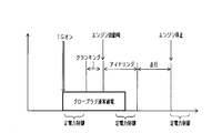
- the GCU 30 performs the rapid temperature increase, but without performing the constant power control. Start resistance value control. That is, in this state, the GCU 30 performs resistance value control using the target resistance value Tg stored at the previous time (time t5).
- FIG. 7 is a flowchart illustrating a process performed in a predetermined period after the engine 10 is stopped (after the IG is turned off) in the flowchart illustrating the process illustrated in FIG. 6.
- the flowchart shown in FIG. 7 is processing performed by the GCU 30 after IG OFF is established.
- step S21 an elapsed time after IG OFF is established is acquired.
- the elapsed time is acquired in order to determine the period after the IG is turned off, and is updated each time the process shown in FIG. 7 is repeated.
- the GCU 30 acquires the elapsed time based on an output from a timer (not shown).
- step S22 it is determined whether IG is on. After the IG is turned off, the GCU 30 determines whether or not the IG-on command input SI is transmitted again from the ECU 50.
- step S22 If it is not determined that IG is on (step S22: NO), the process proceeds to step S23. On the other hand, if it is determined that IG is on (step S22: YES), in step S24, the temperature control of the glow plug 17 is performed, and the process ends. By the temperature control executed in step S24, the resistance value control using the previously stored target resistance value Tg is performed.
- step S23 it is determined whether or not the time until the main relay 26 is turned off has elapsed.
- the GCU 30 makes the determination in step S23 based on whether or not the elapsed time updated in step S21 has passed the time that the main relay 26 is turned off. If the time has not elapsed (step S23: NO), since the main relay 26 is kept on, the GCU 30 returns to step S21 and updates the elapsed time. On the other hand, if the time has passed (step S23: YES), the main relay 26 is then turned off, and the process is terminated.
- the GCU 30 When the IG is turned on again after the main relay 26 is turned off, the GCU 30 performs the process shown in FIG. 4 as in the first embodiment. Therefore, the GCU 30 acquires the target resistance value Tg in the glow plug 17 by performing constant power control (FIG. 4, step S14), and performs resistance value control (FIG. 4, step S17). On the other hand, when performing the process of step S24, the process shown in FIG. 8 is implemented.
- a temperature increase time Tim_r which is a period for performing rapid temperature increase.
- the GCU 30 changes the temperature increase time Tim_r according to the length of the period from when IG is turned off until IG is turned on. Specifically, the temperature increase time Tim_r is acquired according to the count value updated in step S21 of FIG.
- FIG. 9 is a diagram illustrating the setting of the temperature raising time Tim_r performed in step S31.
- the GCU 30 sets the value so that the temperature increase time Tim_r becomes shorter as the elapsed time acquired in step S21 of FIG. 7 is shorter.
- the amount of decrease in the temperature of the glow plug 17 is smaller, and if the temperature of the glow plug 17 is increased, the temperature of the glow plug 17 may become excessive.
- the glow plug 17 is formed of a material having a low resistance value for the purpose of increasing the rate of temperature rise, the glow plug 17 may be deteriorated if the temperature of the glow plug 17 is excessively increased. Therefore, in this 2nd Embodiment, the implementation time of rapid temperature rising is varied according to the period after IG-off is established until IG-on is established again.
- step S32 rapid temperature increase is performed. Therefore, the GCU 30 performs the rapid temperature increase for the glow plug 17 for the temperature increase time Tim_r set in step S31.
- step S33 it is determined whether the temperature increase time Tim_r set in step S32 has elapsed.
- step S33 When the temperature raising time Tim_r has elapsed (step S33: YES), the stored target resistance value Tg is read in step S34. Also in this embodiment, the GCU 30 reads the target resistance value Tg of each of the glow plugs 17 # 1 to 17 # 4.
- step S35 resistance value control is performed.
- the GCU 30 connects the glow plugs 17 # 1 to 17 # 4 so that the resistance values Rg of the glow plugs 17 # 1 to 17 # 4 approach the target resistance value Tg read in step S34 (that is, the previously acquired target resistance value). 17 energization is controlled.
- the GCU 30 maintains the main relay 26 for supplying power after the IG switch 25 (power switch) is turned off for a predetermined time in the engine control system 100 (control). System). Then, GCU 30 controls the resistance values of glow plugs 17 # 1 to 17 # 4 using the target resistance value that is already stored when the time from the stop to restart of engine 10 is within a predetermined time. To do. With the above configuration, when the time from when the engine 10 is stopped to when the engine is restarted is short, resistance value control is performed using the target resistance value that has already been stored. Can be shortened.
- the GCU 30 shortens the period for performing rapid temperature increase after restarting as the period from when the engine 10 is stopped to when it is restarted becomes shorter.
- FIG. 10 is an operation chart showing the timing at which the GCU 30 according to the third embodiment performs constant power control and resistance control.
- the GCU 30 performs the constant power control performed to acquire the target resistance value Tg during idling after the engine 10 is started (after cranking is completed) or during a certain period when the IG is off.
- resistance value control for controlling the temperature of the glow plug 17 is performed when the IG is on
- resistance control is performed using the previously acquired target resistance value Tg as shown in the second embodiment when the IG is on. Will be carried out.
- the GCU 30 includes not only the voltage detection unit 32 and the current detection unit 34 corresponding to the number of glow plugs 17 that can be connected, but also includes only one set of the above-described units. It is good also as a structure which implements control. In this case, the constant power control in step S14 and the resistance value control in step S17 in FIG. 4 are performed for each glow plug 17 # 1 to 17 # 4 while shifting the time series.
- the glow plug 17 is a ceramic glow plug, it may be a glow plug that generates heat when energized and changes its own resistance value according to its own temperature change, and may be a metal glow plug.
- the engine 10 includes four glow plugs 17, and the number of glow plugs 17 corresponding to the number of cylinders may be provided.
- glow plug 17 as the heating element is merely an example, and any type may be used as long as it is provided in the engine 10 and temperature control is performed.
Landscapes
- Engineering & Computer Science (AREA)
- Mechanical Engineering (AREA)
- Chemical & Material Sciences (AREA)
- Combustion & Propulsion (AREA)
- General Engineering & Computer Science (AREA)
- Physics & Mathematics (AREA)
- Thermal Sciences (AREA)
- Combined Controls Of Internal Combustion Engines (AREA)
- Control Of Resistance Heating (AREA)
Abstract
発熱体制御装置30は、エンジン10の始動要求に応じて、複数の発熱体17に一定の電力を供給することで各発熱体17の温度を目標温度に制御する温度制御部と、目標温度における各発熱体17の抵抗値を目標抵抗値として取得する抵抗値取得部と、各発熱体17の抵抗値が対応する目標抵抗値に維持されるよう、各発熱体17の抵抗値を個別に制御する抵抗制御部と、を有している。また、温度制御部は、エンジン10の始動要求が行われた後、エンジン10の始動前に発熱体17に対する前記一定の電力を供給する。
Description
本出願は、2016年2月10日に出願された日本出願番号2016-024087号に基づくもので、ここにその記載内容を援用する。
本開示は、エンジンに備えられる発熱体の温度を制御する発熱体制御装置、及びエンジン制御システムに関する。
従来、エンジンでは、冷間始動時における燃焼性能を確保する等の理由から、各部を所定の温度に保持する発熱体が備えられている。発熱体は、制御装置を介して電源と接続されており、この制御装置によりその温度が一定となるよう制御される。
特許文献1には、発熱体の一例であるグロープラグの温度制御が開示されている。特許文献1で開示された温度制御では、まず、グロープラグが使用されるタイミングで、制御部は、新たに交換されたグロープラグの所定温度での抵抗値を取得し、この抵抗値を目標抵抗値とする。次に、制御部は、このグロープラグを目標温度に到達させるために必要な目標電力量を取得する。そして、制御部は取得した目標電力量をグロープラグに投入しグロープラグを目標温度となるように制御する。
例えば、エンジンは気筒毎に複数の発熱体を備えているが、発熱体は個体差がありその抵抗値にばらつきが存在する。また、発熱体は使用を継続することで経年劣化し、抵抗値を変化させる。抵抗値に経年変化があると発熱体の抵抗値を設定した値になるよう制御しても、発熱体の温度が変化してエンジン冷間始動時の燃焼性能を確保できなくなってしまう場合がある。そのため、特許文献1に記載したように、発熱体の交換後、1度だけこの発熱体の抵抗値を取得し、取得した抵抗値により発熱体を制御する方法では、経年劣化などによる抵抗値の変化に対応できず、発熱体を交換して抵抗値取得作業を実施しないかぎり各発熱体の温度制御が適正に実施されない場合がある。
本開示は、上記課題に鑑みてなされたものであり、発熱体の温度のばらつきを特別な作業を必要とせず、自動的に少なくすることができる発熱体制御装置、又はエンジン制御システムを提供することを目的とする。
本開示では、エンジンに備えられた発熱体の温度を制御する発熱体制御装置であって、前記発熱体に一定の電力を供給することで前記発熱体の温度を目標温度に制御する温度制御部と、前記目標温度における前記発熱体の抵抗値を目標抵抗値として取得する抵抗値取得部と、前記発熱体の抵抗値が前記目標抵抗値に維持されるよう、前記発熱体の抵抗値を制御する抵抗制御部と、を有し、前記温度制御部は、前記エンジンの始動要求が行われた後、前記エンジンの始動前に前記発熱体に対して前記一定の電力を供給し、前記抵抗制御部は、前記エンジンの始動前に前記発熱体に対して前記一定の電力を供給することで求められた前記目標抵抗値に、前記発熱体の抵抗値を維持する。
このため、温度制御部が発熱体に対して一定の電力を供給することで発熱体の温度が供給電力量と相関する所定の温度で定常状態となる。発熱体の温度が定常状態となると、温度とともに変化していた発熱体の抵抗値は個々のばらつきに応じた値に収束する。また、発熱体に対する供給電力が一定であり、同じ仕様の発熱体では放熱特性も一定であるため、発熱体の温度が物性に応じた温度に収束する。即ち、この状態で取得される発熱体の各抵抗値は、発熱体の温度を一致させた状態で得られたものとなる。そして、抵抗制御部は発熱体の抵抗値が定常状態における抵抗値に維持されるよう、発熱体の抵抗値を個別に抵抗値制御する。そのため、経年劣化等に伴い発熱体に抵抗値の変化が生じる場合でも、発熱体の温度を所定の範囲に維持することが可能となる。
本開示についての上記目的およびその他の目的、特徴や利点は、添付の図面を参照しながら下記の詳細な記述により、より明確になる。その図面は、
図1は、エンジン制御システムの全体概略を示す構成図であり、
図2は、GCUの回路構成を示す概略図であり、
図3は、グロープラグに対する制御を説明する図であり、
図4は、グロープラグに対する制御を示すフローチャートであり、
図5は、グロープラグに対する制御において各値の変化を示す動作チャートであり、
図6は、第2実施形態に係るGCUの動作を説明する動作チャートであり、
図7は、IGオフ後の所定期間において実施される処理を示すフローチャートであり、
図8は、ステップS24において実施される処理を説明する図であり、
図9は、ステップS31で実施される昇温時間Tim_rの設定を説明する図であり、
図10は、第3実施形態に係るGCUが定電力制御と抵抗制御を実施するタイミングを示す動作チャートである。
(第1の実施形態)
以下、本開示を具体化した第1の実施の形態について図面を参照しつつ説明する。本実施形態は、ディーゼルエンジンを対象にエンジン制御システムを構築するものである。なお、以下の実施形態相互において、互いに同一もしくは均等である部分には、図中、同一符号を付しており、同一符号の部分についてはその説明を援用する。
以下、本開示を具体化した第1の実施の形態について図面を参照しつつ説明する。本実施形態は、ディーゼルエンジンを対象にエンジン制御システムを構築するものである。なお、以下の実施形態相互において、互いに同一もしくは均等である部分には、図中、同一符号を付しており、同一符号の部分についてはその説明を援用する。
図1は、本実施形態におけるエンジン制御システムの全体概略を示す構成図である。エンジン制御システム100は、エンジン10と、バッテリ21と、グローコントロールユニット30(以下、GCUとも記載する)と、ECU(Electronic Control Unit)50と、を備えている。
エンジン10は、内燃運動を行う周知の内燃機関である。例えば、この実施形態では、エンジン10は、4気筒のエンジンとして説明される。図1において、エンジン10の吸気ポート及び排気ポートにはそれぞれ吸気バルブ11及び排気バルブ12が設けられている。燃焼室14には、燃料噴射弁16の先端部が突出されており、この燃料噴射弁16により燃料供給が行われる。そして、燃焼室14内の圧縮に伴い燃料が自己着火して燃焼が行われる。また、吸気バルブ11の開動作により空気が吸気管(吸気通路)13から燃焼室14内に導入され、排気バルブ12の開動作により燃焼後の排ガスが排気管(排気通路)15に排出される。
エンジン10の燃焼室14には発熱体として機能するグロープラグ17が配置されている。グロープラグ17は、例えば、セラミックス製のヒータを有するセラミックグロープラグである。グロープラグ17は、その先端部が燃焼室14に突出して配置されており、発熱により燃焼室14内のガスを暖めることでエンジン10の燃料の着火性を向上させる。本実施形態では、各気筒にそれぞれ配置された4つのグロープラグを備えており、各グロープラグを区別するときは、17♯1,17♯2,17♯3,17♯4の符号を付すものとする。ここで、グロープラグ17の温度と記載するときは、グロープラグ17におけるヒータの温度を意味し、グロープラグ17の抵抗と記載するときは、ヒータの抵抗を意味する。
GCU30は、グロープラグ17への電力の供給を制御する。GCU30は、グロープラグ17とバッテリ21とにそれぞれ接続されており、バッテリ21からグロープラグ17への通電を制御する。なお、GCU30の詳細な構成については後述する。
バッテリ21は、電源として機能し、エンジン制御システム100の各部に電力を供給する。バッテリ21は、例えば、直流電源を供給する鉛蓄電池であり、図示されたGCU30やECU50の他、不図示の負荷に対しても電力を供給する。
バッテリ21とECU50及びGCU30との間にはメインリレー26が介在している。メインリレー26は、バッテリ21とECU50及びGCU30とを繋ぐ経路を開閉する開閉器としても機能する。メインリレー26は、例えば、経路を繋ぐスイッチと、このスイッチを作動させるソレノイドとで構成されている。
ECU50は、エンジン制御システム100の駆動を統合的に制御する。ECU50は、例えば、CPU、ROM、RAM等を備えるマイクロコンピュータを主体として構成されている。そして、CPUがROMに記憶された各種の制御プログラムを実行することで、エンジン運転状態に応じてエンジン10の各種制御を実施する。また、ECU50は、エンジン10にバッテリ21を繋ぐことで始動要求を生じさせるIG(イグニッション)スイッチ25、クランク軸18の回転角度を検出するクランク角センサ22、エンジン水温を検出する水温センサ23、外気温を検出する外気温センサ24、と接続されている。
ECU50は、グロープラグ17への電力供給に関して、都度のエンジン運転状態に基づいて指令入力SIを算出してGCU30に出力する。エンジン運転状態として具体的には、エンジン回転速度やエンジン水温、外気温、燃料噴射量等が挙げられる。
次に、GCU30について詳細に説明する。図2は、GCU30の回路構成を示す概略図である。GCU30は、バッテリ端子41及び制御系電源端子42を介してバッテリ21と接続され、このバッテリ端子41及び制御系電源端子42を介してバッテリ21から電力の供給を受ける。この内、制御系電源端子42はメインリレー26を介してバッテリ21と接続されている。また、GCU30は、通信端子43,44を介してECU50と接続され、この通信端子43,44を介してECU50との間で通信を行う。そして、GCU30は、出力端子46を介してグロープラグ17に接続されている。なお、GCU30は、グランド端子45を介して、グランドと接続されている。
GCU30は、その機能として、スイッチング部31、電圧検出部32、電流検出部34、制御部37を備えている。例えば、GCU30はワンチップマイコンにより構成されており、上記したスイッチング部31、電圧検出部32、電流検出部34、制御部37はこのワンチップマイコンの機能ブロックとして構成されている。なお、GCU30はマイコンにより構成されるものに限定されず、上述した各部をハードウェア回路により構成するものであっても良い。
GCU30は、グロープラグ17♯1~17♯4毎に、スイッチング部31、電圧検出部32、電流検出部34を備えている。なお、図2では、便宜上、グロープラグ17♯1に対応するスイッチング部31、電圧検出部32、電流検出部34を記載し、他のグロープラグ17♯2~17♯4に対応する構成は記載を省略している。
スイッチング部31は、オン・オフ動作によりグロープラグ17の給電を制御する。スイッチング部31は、例えばMOSトランジスタからなるスイッチ素子TRを備えている。スイッチ素子TRのドレインはバッテリ端子41を介してバッテリ21と接続され、そのソースは出力端子46を介してグロープラグ17に接続されている。また、スイッチ素子TRのゲートは制御部37の出力端子に接続されている。
電圧検出部32は、グロープラグ17の電圧値Vgを検出し、検出した電圧値Vgを制御部37に出力する。電圧検出部32の検出端子はスイッチング部31のソースと出力端子46とを繋ぐノードに接続され、その出力端子は制御部37の入力端子に接続されている。
電流検出部34は、グロープラグ17の電流値Igを検出する。この実施形態では、電流検出部34は、バッテリ21からの通電時(スイッチング部31のオン時)及びバッテリ21からの非通電時(スイッチング部31のオフ時)の電流を検出できるよう、異なる部位(通電時電流検出部35、非通電時電流駆動部36)を備えている。
通電時電流検出部35は、バッテリ21からの通電時におけるグロープラグ17の電流値を検出する。通電時電流検出部35は、センス抵抗R1とこのセンス抵抗R1の両端の値を演算する演算アンプOPとを備えている。センス抵抗R1の一端は、スイッチ素子TRのセンス端子に接続されている。演算アンプOPは、バッテリ21による通電時に、センス抵抗R1に生じる電圧値に応じた出力を制御部37に出力する。この出力は、グロープラグ17の電流値に応じて値が変化するため、制御部37は通電時電流検出部35からの出力と電圧検出部32からの出力に基づいて印加電力を求め、又グロープラグの発熱体の抵抗値を求めることで、グロープラグ17の電流値を制御することができる。
非通電時電流駆動部36は、抵抗R2を備えており、この抵抗R2の一端は定電流源に接続され、抵抗R2のもう一端はスイッチ素子TRのソースと出力端子46とを繋ぐノードに接続されている。制御部37は、スイッチ素子TRのオフ時において、定電流源からの電流を非通電時電流駆動部36よりグロープラグ17に流す。定電流源からの電流はその値が一定であるため、制御部37は、電圧検出部32で検出したグロープラグ17に発生する非通電時の電圧値と、定電流源からの駆動電流と、から発熱体の抵抗値を検出することができる。
なお、グロープラグ17の抵抗値Rgが低い値である場合、非通電時電流駆動部36の抵抗R2はこのグロープラグ17の抵抗値Rgと同様に低い値であることが望ましい。また、非通電時電流駆動部36を定電流源に接続することは一例に過ぎない。これ以外にも、非通電時電流駆動部36は、定電圧源のみに接続され、抵抗R2とグロープラグ17との抵抗値Rgとの分圧比に応じた電流値を、オペアンプ等を介して制御部37に出力するものであってもよい。更には、非通電時電流駆動部36を常に通電しておき、制御部37はスイッチ素子TRがオンとなる通電時における電流を通電時電流検出部35で求まる電流値に定電流分を加算して制御してもよい。この場合、制御部37は、グロープラグ17への通電と非通電時の発熱体の抵抗値の検出を電流出力と電圧検出のタイミングずれによる誤差を抑えることができる。この場合、制御部37と非通電時電流駆動部36とは電気的に接続されていなくともよい。
また、制御部37は、電圧検出部32で取得した電圧を、電流検出部34および、非通電時電流駆動部36で取得した電流で除することでグロープラグ17の抵抗値Rgを検出する。この実施形態では、制御部37は、バッテリ21からの通電時において、通電時電流検出部35により検出された電流Igを用いて抵抗値Rgを検出する。また、制御部37は、バッテリ21からの非通電時において、非通電時電流駆動部36の駆動に応じて検出された電流Ig(非通電時電流値)を用いて抵抗値Rgを検出する。そのため、この実施形態では、制御部37が抵抗検出部としても機能する。
制御部37は、スイッチング部31の駆動を制御する。制御部37は、例えば、周知のCPU、ROM、RAM等よりなるマイクロコンピュータ(以下、マイコンという)を主体として構成されている。制御部37は、通信端子43を介してECU50からの指令入力SIを受信し、各スイッチング部31を動作させるゲート信号を出力する。例えば、このゲート信号により、グロープラグ17♯1~17♯4には、所定周期(例えば30msec)毎に通電タイミングが到来するよう通電が行われる。また、制御部37は、グロープラグ17の異常診断時において異常を検出すると、通信端子44を介してECU50に診断結果を出力する。
次に、グロープラグ17の温度制御を、図3A,図3Bを用いて説明する。抵抗値にばらつきが生じている4つのグロープラグ17♯1~17♯4に対する温度変化を図3Aで示し、抵抗値変化を図3Bで示している。
GCU30はIGスイッチ25のオン操作(以下、IGオンとも記載する。)毎に、一定の温度となったグロープラグ17を温度制御する(抵抗値制御)。また、この実施形態では、グロープラグ17の温度を定常状態での目標温度に保持するために定電力制御が、IGオン毎に最大電力で駆動する急速昇温動作の後に実施される。この定電力制御は、不図示のスタータによるエンジン10の始動(クランキング)が開始されるまでなど、グロープラグ温度に影響を与える外乱が少ない期間において実施される。
急速昇温は、グロープラグ17の温度が増加するようグロープラグ17を一定の時間までバッテリ電圧を印加し急速昇温させる。例えば、急速昇温は、PWM通電の駆動Dutyを100%で電圧を印加し、かつ昇温を行う時間が所定値に設定されたオープン制御により実施される。
定電力制御は公知技術(特許4941391号)と同様に、所定の一定周期で通電をオンし、電圧および電流から算出される積算電力が設定値になると通電をオフさせるよう、オンとオフを繰り返す制御である。また、設定積算電力値に達したときの抵抗値を求める。このように、電圧検出部32で検出されるグロープラグ17の電圧値Vg及び電流検出部34で検出されるグロープラグ17の電流値Igに基づいて、供給電力が一定の値となるようグロープラグ17に対する通電が制御される。この定電力制御は、図3(a)に示すように、グロープラグ17の温度が所定の範囲となる定常状態に達するまで継続される。定常状態でのグロープラグ17♯1~17♯4の各温度は、グロープラグ17の放熱特性がほぼ同じであるためグロープラグ17の比熱又は材質等により定まり、各グロープラグ17♯1~♯4の温度は同じ温度に収束する。一方で、図3(b)に示すように、定常状態に収束したときのグロープラグ17の抵抗値Rg1~Rg4は、個々のバラツキや経時変化などにより異なる値にばらついている。
更に、グロープラグ17の各抵抗値が所定の範囲内となったことによりグロープラグ17の温度が一定の定常状態となったと判定すると、定電力制御で求めた各抵抗値を制御目標とした抵抗値制御によりグロープラグ17の抵抗値が定電力制御時の定常状態での抵抗値に維持されるよう制御される。この第1実施形態では、検出されたグロープラグ17の各抵抗値Rg1,2,3,4を各制御目標値としてこの値に維持されるよう抵抗値を検出しながらスイッチング部31のオン・オフ制御が実施される。図3(b)では、グロープラグ17♯1~17♯4に対してそれぞれ抵抗値Rg1~Rg4が一定の範囲に維持され、グロープラグ17の温度が定電力制御で収束させた温度に保持される。
次に、図3(a),図3(b)で示すグロープラグ17に対する制御を図4に示すフローチャートを用いて説明する。図4のS12以降に示す処理は、IGスイッチ25がオンされる毎に、GCU30により実施される処理を示す。図4に示すフローチャートにおいて、GCU30がステップS12~S15の処理を実施することで温度制御部として機能し、ステップS16の処理を実施することで抵抗値取得部として機能し、S17の処理を実施することで抵抗制御部として機能する。また、図5(a)~図5(c)は、グロープラグ17に対する制御において各値の変化を示す動作チャートである。
ステップS11では、IGオンを判定する。例えば、IGスイッチ25が操作されてメインリレー26がオンされることで、GCU30にバッテリ21からの電源が供給されると、GCU30はIGオンを判定する。GCU30はこのIGオンの判定により、エンジン10に対する始動要求が生じたことを判定する。なお、ステップS11では、IGオンによりECU50が、始動要求が生じたことを判定し、GCU30に通電指令を送信することでGCU30がエンジン10に対する始動要求が生じたことを判定してもよい。
IGオンを判定した場合(ステップS11:YES)、ステップS12では、急速昇温を実施する。図5(a)に示すように、急速昇温では、GCU30は、Dutyが100%となるようスイッチング部31制御し、このときのバッテリ電圧の印加によりグロープラグ17を昇温する。この急速昇温によりグロープラグ17の温度は急速に上昇する。
ステップS13では、昇温時間Tim_rの経過を判定する。ステップS13における昇温時間Tim_rは、例えば、100%のバッテリ電圧の印加でグロープラグ17が所定の温度に到達するのに必要な時間として予め定められた時間である。即ち、急速昇温をこの昇温時間Tim_rだけ実施することで、グロープラグ17の温度は急速に所定の温度範囲に達することとなる。
昇温時間Tim_rが経過したことを判定した場合(ステップS13:YES)、ステップS14では、定電力制御を実施する。図5(a)に示すように、定電力制御が実施される期間では、GCU30は、所定期間において検出された電圧値Vgと電流値Igとを乗算して得たオン期間の電力を積算し、所定の積算値で通電をオフし、一定周期で通電をオンすることで、周期毎の積算電力が所定の積算値で一定となるようグロープラグ17に対する通電を繰り返し制御する。
グロープラグ17は投入される電力に応じて温められ、図5(b)に示すようにその抵抗値Rgを変化させる。
ステップS15では、グロープラグ17の抵抗値Rgの変化を監視する。この実施形態では、グロープラグ17の通電時では通電時電流検出部35が検出する電流値Ig基づいて、又、非通電時では非通電時電流駆動部36の駆動による電流値Igに基づいて、GCU30は抵抗値Rgを監視する。なお、この実施形態では、GCU30はグロープラグ17♯1~17♯4のそれぞれの抵抗値Rg♯1~♯4を監視する。
ステップS15において抵抗値Rgの監視が継続される期間は、グロープラグ17の所定タイミングでの抵抗値Rgが一定の範囲(定常状態)に収束するか否かに基づいて判定する。例えば、GCU30は、通電オフ直前の抵抗値Rgを記憶しており、前回と今回との抵抗値Rgの差が閾値以下となれば一定の範囲に収束したと判定する。図5(b)では、図中右側において、抵抗値Rgが一定の範囲に収束しており、GCU30は収束判定を行っている。なお、収束判定は、通電オン開始時の前回と今回との抵抗値の差が所定値以下となった場合や、定電力制御のオン時間の前回と今回との差が所定値以下となった場合、更には所定周期で別途計測したグロープラグ温度の前回と今回との差が所定値以下となった場合に収束したと判定してもよい。これ以外にも、抵抗値Rgが所定回数連続して範囲内となったことで収束判定を実施してもよい。
抵抗値Rgの変化が収束した場合、ステップS16では、このときの抵抗値Rgを目標抵抗値Tgとして取得する。この目標抵抗値Tgは、抵抗値制御におけるターゲットとなる値である。この実施形態では、グロープラグ17♯1~17♯4に対してそれぞれ目標抵抗値Tg♯1~Tg♯4がIGオン毎に取得される。なお、目標抵抗値Tgは抵抗値Rgの収束点の直前の複数の値を平均化して求めても良い。
ステップS16における各グロープラグ17♯1~17♯4に対応する目標抵抗値Tg♯1~Tg♯4の取得タイミングは、ステップS15において、全てのグロープラグ17♯1~17♯4の抵抗値Rgが収束したことを条件に実施される。これ以外にも、ステップS15において、各グロープラグ17♯1~17♯4の抵抗値が個別に収束した場合に、ステップS16でそれぞれの目標抵抗値Tg♯1~Tg♯4が取得されるものであってもよい。
ステップS17では、抵抗値制御を実施する。抵抗値制御では、GCU30は、各グロープラグ17♯1~17♯4の抵抗値RgがステップS16で取得された対応する目標抵抗値Tg(♯1~♯4)に近づくよう、グロープラグ17に対する通電を制御する(図5(a))。例えば、抵抗値Rgが目標抵抗値Tgよりも大きくなる場合、GCU30はバッテリ電圧の通電をオフする。一方、抵抗値Rgが目標抵抗値Tgよりも所定値以上小さくなった場合、GCU30はバッテリ電圧の通電をオンする。なお、図5(c)では、便宜上、抵抗値制御における電力変化の記載を省略している。
抵抗値制御は、IGスイッチ25の操作によりエンジン10がオフ(IGオフとも記載する)されることで終了され、図4で示した処理を終了する。
以上説明したようにこの第1実施形態に係るGCU30(発熱体制御装置)によれば、GCU30がグロープラグ17に対して定電力制御を実施することで各グロープラグ17の温度が所定の値に達して定常状態となる。グロープラグ17の温度が定常状態となると、グロープラグ17の抵抗値は個々のばらつきに応じた値に収束する。また、各グロープラグ17に対する供給電力が一定であるため、各グロープラグ17の温度が物性に応じた温度に収束する。即ち、この状態で取得されるグロープラグの各抵抗値は、各グロープラグ17の温度を一致させた状態で得られたものとなる。そして、GCU30はグロープラグ17の抵抗値が定常状態における抵抗値(目標抵抗値)に維持されるよう、各グロープラグ17の抵抗値を個別に抵抗値制御する。そのため、経年劣化等に伴いグロープラグ17毎に抵抗値のばらつきが生じる場合でも、各グロープラグ17の温度を所定の範囲に維持することが可能となる。
ここで、経年劣化によりグロープラグ17の抵抗値は長い時間で徐々に変化する。そのため、IGオンに伴う通電開始の都度、定電力制御を実施することで、グロープラグ17の温度を所定の範囲に維持するための抵抗値Rgを取得することが可能となる。例えば、経年劣化が進行することで抵抗値Rgが上昇した場合は、印加電流が低下しても定電力制御により印加される実効電圧を増加させることで、結果として同じ電力量が投入されるため、経年劣化に伴う抵抗値Rgの上昇前のグロープラグ17と同じ温度となる抵抗値Rgが取得できる。そして、取得された抵抗値Rgを用いた抵抗値制御によりグロープラグ17の温度を劣化前と同じ所定の範囲に維持することが可能となる。
また、エンジンの始動要求前といった昇温動作に対する影響が少ない状態で、GCU30が定電力制御を所定時間実施することで、常に一定の電力がグロープラグ17に印加される。そのため、経年劣化による抵抗値が変化したグロープラグ17であってもその温度は常に物性に応じた所定の温度に収束する。そして、このときの抵抗値Rgを維持するための抵抗値制御を実施することで、エンジン10が始動されバッテリ電圧の変動や筒内気流によるグロープラグ17の温度変化が発生した場合でも、定電力制御の実施により得られた所定の温度に対応し、且つ経年変化を含む抵抗値を狙いとした抵抗値制御が実施される。抵抗値制御を実施すると電源電圧の変動や筒内気流による冷却などでグロープラグ17の温度が変化しても、グロープラグ17の抵抗値を一致させるよう通電制御を実施する。その結果、グロープラグ17の温度を一定に制御できる。
ここで、エンジン10の始動要求とは、運転者がIGスイッチ25を操作することでメインリレー26がオンされる場合を意味し、エンジン10を始動させる以外にも、いわゆるアイドリングストップ後のエンジン10の再始動も含む概念である。また、エンジン10の始動に伴う外乱とは、例えば、エンジン10のクランクシャフトの回転がスタータにより開始されることで生じるバッテリ21の急速な電圧低下や気筒内に発生する気流の流れによるグロープラグ17の冷却による温度の低下を意味している。
GCU30は、グロープラグ17♯1~17♯4の定電力制御前に、グロープラグ17♯1~17♯4を所定時間だけ継続通電させ昇温する(急速昇温)。上記構成により、グロープラグ17♯1~17♯4の温度を定常状態まで変化させるのに要する時間を短くすることができ、又、目標抵抗値を早い時間で求めることができ、抵抗制御を開始するまでに要する時間を短くすることができる。
GCU30は、グロープラグ17♯1~17♯4の抵抗値の変化量が所定範囲に収まった場合、グロープラグ17♯1~17♯4に対して抵抗値制御を実施する。上記構成により、グロープラグ17♯1~17♯4の抵抗値が定常状態に至ったことを、抵抗値の変化量から判定することができるため、判定に必要な処理を簡素化し、処理負荷を低減することができる。
(第2実施形態)
この第2実施形態では、エンジン10が停止されてから再度、エンジン10が始動されるまでの時間に応じて、GCU30が目標抵抗値Tgを新たに取得するか、すでに取得している目標抵抗値Tgを流用するかを切り替える。
この第2実施形態では、エンジン10が停止されてから再度、エンジン10が始動されるまでの時間に応じて、GCU30が目標抵抗値Tgを新たに取得するか、すでに取得している目標抵抗値Tgを流用するかを切り替える。
図6は、第2実施形態に係るGCU30の動作を説明する動作チャートである。図6では、IGオンからIGオフまでの期間に応じて、グロープラグ17の各温度制御(急速昇温、定電力制御、抵抗値制御)の実施の有無が変化している。なお、期間TAと期間TBとは、TA>TBの関係を有している。
例えば、時刻t1で運転者がIGスイッチ25を操作してIGオンが成立すると、GCU30は急速昇温を開始する。その後、GCU30が定電力制御を開始する前に時刻t2で運転者がIGスイッチを操作してIGオフが成立したとする。その後、期間TA経過後に、時刻t3でIGオンが成立すると、GCU30は急速昇温を再開し、時刻t4において定電力制御を開始する。その後、時刻t5においてグロープラグ17が定常状態に達すると、求めた抵抗値Rgから目標抵抗値Tgを求めてGCU30は目標抵抗値Tgに一致するよう抵抗値制御を開始する。
また、時刻t6においてIGオフが成立したとする。このとき、期間TB後のメインリレー26のオンが維持されている期間において、再度、IGオンが成立すると(時刻t7)、GCU30は急速昇温を実施するが、定電力制御を実施することなく抵抗値制御を開始する。すなわち、この状態において、GCU30は、前回(時刻t5)で記憶した目標抵抗値Tgを用いて抵抗値制御を実施する。
図7は、図6に示す処理を説明するフローチャートのうち、エンジン10の停止後(IGオフ後)の所定期間において実施される処理を示すフローチャートである。例えば、図7に示すフローチャートは、IGオフが成立した後、GCU30により実施される処理である。
まず、ステップS21では、IGオフが成立してからの経過時間を取得する。経過時間は、IGオフ後の期間を判定するために取得され、図7に示す処理が繰り返される毎に更新される。GCU30は、例えば、不図示のタイマーからの出力により経過時間を取得する。
ステップS22では、IGオンを判定する。GCU30はIGオフ後に、ECU50から再度のIGオンの指令入力SIが送信されたか否かの判定を行う。
IGオンを判定しなければ(ステップS22:NO)、ステップS23に進む。一方、IGオンを判定すれば(ステップS22:YES)、ステップS24では、グロープラグ17の温度制御を実施し、処理を終了する。ステップS24で実行される温度制御により、前回記憶されている目標抵抗値Tgを流用する抵抗値制御が実施される。
ステップS23では、メインリレー26がオフされるまでの時間が経過したか否かを判定する。GCU30はステップS21で更新される経過時間が、メインリレー26がオフされる時間が経過したか否かに基づいてステップS23の判定を行う。時間経過していなければ(ステップS23:NO)、メインリレー26のオンは維持されているため、GCU30はステップS21に戻り経過時間を更新する。一方、時間経過に達していれば(ステップS23:YES)、メインリレー26はその後オフされるため、処理を終了する。
メインリレー26のオフ後、再度、IGオンが成立した場合、GCU30は、第1実施形態同様、図4に示す処理を実施する。そのため、GCU30は、定電力制御(図4、ステップS14)を実施することでグロープラグ17における目標抵抗値Tgを取得し、抵抗値制御(図4、ステップS17)を実施する。一方、ステップS24の処理を実施する場合、図8に示す処理が実施される。
次に、メインリレー26がオンされている期間内においてIGオンが成立した場合の処理を、図8を用いて説明する。ステップS31では、急速昇温を実施する期間である昇温時間Tim_rを設定する。この第2実施形態では、GCU30はIGオフが成立してからIGオンが成立するまでの期間の長さに応じて、昇温時間Tim_rを変化させる。具体的には、図7のステップS21で更新されたカウント値に応じて昇温時間Tim_rが取得される。
図9は、ステップS31で実施される昇温時間Tim_rの設定を説明する図である。この第2実施形態では、GCU30は、例えば、図7のステップS21で取得される経過時間が短いほど、昇温時間Tim_rが短くなるようその値を設定する。経過時間が短いほど、グロープラグ17の温度の低下量が少なく、グロープラグ17の温度を上昇させると、グロープラグ17の温度が過剰な温度となる虞がある。特に、昇温速度を高めることを目的にグロープラグ17を抵抗値の低い材質で形成している場合、グロープラグ17の温度を高め過ぎるとグロープラグ17を劣化させる虞がある。そのため、この第2実施形態では、IGオフが成立してから再度のIGオンが成立するまでの期間に応じて、急速昇温の実施時間を可変させている。
図8に戻り、ステップS32では、急速昇温を実施する。そのため、GCU30は、グロープラグ17に対する急速昇温をステップS31で設定された昇温時間Tim_rで実施する。そして、ステップS33では、ステップS32で設定された昇温時間Tim_rの経過を判定する。
昇温時間Tim_rが経過すると(ステップS33:YES)、ステップS34では、記憶済みの目標抵抗値Tgを読み出す。この実施形態においても、GCU30は、グロープラグ17♯1~17♯4のそれぞれの目標抵抗値Tgを読み出す。
ステップS35では、抵抗値制御を実施する。抵抗値制御では、GCU30は各グロープラグ17♯1~17♯4の抵抗値RgがステップS34で読みだされた目標抵抗値Tg(即ち、前回取得された目標抵抗値)に近づくよう、グロープラグ17の通電を制御する。
以上説明したようにこの第2実施形態では、GCU30は、IGスイッチ25(電源スイッチ)のオフ操作後に電源を供給するためのメインリレー26を所定時間、オン状態で維持するエンジン制御システム100(制御システム)に適用されている。そして、GCU30は、エンジン10の停止から再始動までの時間が所定時間内となる場合、既に記憶されている目標抵抗値を使用して、グロープラグ17♯1~17♯4の抵抗値を制御する。上記構成により、エンジン10が停止されてから再始動までの時間が短い場合、すでに記憶されている目標抵抗値を使用して抵抗値制御を実施するため、再始動後の抵抗の制御を開始するまでの時間を短くすることができる。
GCU30は、エンジン10が停止されてから再始動するまでの期間が短くなるに従い、再始動後の急速昇温を実施する期間を短くする。上記構成により、エンジン10が停止されてから再始動するまでの時間が短い場合、急速昇温を実施する期間が短くなるため、グロープラグ17♯1~17♯4の温度の過上昇を抑制することができ、温度の過上昇に伴うグロープラグ17♯1~17♯4の劣化を抑制することができる。
(第3実施形態)
この第3実施形態では、グロープラグ17の抵抗値(目標抵抗値)の取得を、IGオン時以外の所定期間で取得する。図10は、第3実施形態に係るGCU30が定電力制御と抵抗制御を実施するタイミングを示す動作チャートである。
この第3実施形態では、グロープラグ17の抵抗値(目標抵抗値)の取得を、IGオン時以外の所定期間で取得する。図10は、第3実施形態に係るGCU30が定電力制御と抵抗制御を実施するタイミングを示す動作チャートである。
図10では、GCU30は、目標抵抗値Tgを取得するために実施される定電力制御を、エンジン10の始動後(クランキング終了後)のアイドリング時や、IGオフ時の一定期間において実施する。無論、グロープラグ17の温度を制御するための抵抗値制御は、IGオン時において実施されるため、IGオン時は第2実施形態で示したいように前回取得した目標抵抗値Tgを用いて抵抗制御を実施することになる。
(その他の実施形態)
GCU30は、接続可能なグロープラグ17の数に応じた電圧検出部32、電流検出部34を備える以外にも、上述した各部を一組だけ備え、その一組により、全てのグロープラグ17の温度制御を実施する構成としてもよい。この場合、図4のステップS14の定電力制御及びステップS17の抵抗値制御は、各グロープラグ17♯1~17♯4に対して時系列をずらして実施される。
GCU30は、接続可能なグロープラグ17の数に応じた電圧検出部32、電流検出部34を備える以外にも、上述した各部を一組だけ備え、その一組により、全てのグロープラグ17の温度制御を実施する構成としてもよい。この場合、図4のステップS14の定電力制御及びステップS17の抵抗値制御は、各グロープラグ17♯1~17♯4に対して時系列をずらして実施される。
グロープラグ17をセラミックグロープラグとしたが、通電によって発熱するとともに、自身の温度変化に応じて自身の抵抗値が変化するグロープラグであればよく、金属グロープラグとしてもよい。
エンジン10が4個のグロープラグ17を備えることは一例に過ぎず、気筒数に応じた数のグロープラグ17を備える構成としてもよい。
発熱体をグロープラグ17としたことは一例に過ぎず、エンジン10に備えられ、温度制御が実施されるものであればどのようなものであってもよい。
本開示は、実施例に準拠して記述されたが、本開示は当該実施例や構造に限定されるものではないと理解される。本開示は、様々な変形例や均等範囲内の変形をも包含する。加えて、様々な組み合わせや形態、さらには、それらに一要素のみ、それ以上、あるいはそれ以下、を含む他の組み合わせや形態をも、本開示の範疇や思想範囲に入るものである。
Claims (6)
- エンジン(10)に備えられた発熱体(17)の温度を制御する発熱体制御装置(30)であって、
前記発熱体に一定の電力を供給することで前記発熱体の温度を目標温度に制御する温度制御部(S14)と、
前記目標温度における前記発熱体の抵抗値を目標抵抗値として取得する抵抗値取得部(S16)と、
前記発熱体の抵抗値が前記目標抵抗値に維持されるよう、前記発熱体の抵抗値を制御する抵抗制御部(S17)と、を有し、
前記温度制御部は、前記エンジンの始動要求が行われた後、前記エンジンの始動前に前記発熱体に対して前記一定の電力を供給し、
前記抵抗制御部は、前記発熱体の抵抗値を、前記エンジンの始動前に前記発熱体に対して前記一定の電力を供給することで求められた前記目標抵抗値に維持する、発熱体制御装置。 - 前記発熱体は、前記エンジンに複数設けられている、請求項1に記載の発熱体制御装置。
- 前記温度制御部は、前記発熱体に対する前記一定の電力の供給前に、前記発熱体を所定時間昇温する、請求項1又は請求項2に記載の発熱体制御装置。
- 前記温度制御部は、前記エンジンが停止されてから再始動するまでの期間が短くなるに従い、前記再始動後の前記発熱体を昇温する期間を短くする、請求項3に記載の発熱体制御装置。
- 前記抵抗制御部は、前記抵抗値取得部が取得する前記発熱体の抵抗値の変化量が所定範囲に収まった場合、前記発熱体に対する前記抵抗値の制御を実施する、請求項1から請求項4のいずれか一項に記載の発熱体制御装置。
- エンジン(10)に備えられた発熱体(17)の温度を制御する発熱体制御装置(30)と、前記発熱体制御装置に電源を供給するためのメインリレー(26)と、電源スイッチのオフ操作後に前記メインリレーを所定期間だけオン状態に維持する制御装置(50)と、を有するエンジン制御システムであって、
前記発熱体に一定の電力を供給することで発熱体の温度を定常状態に制御する温度制御部(S14)と、
前記定常状態における前記発熱体の抵抗値を目標抵抗値として取得する抵抗値取得部(S16)と、
前記各発熱体の抵抗値が対応する前記目標抵抗値に維持されるよう、前記発熱体の抵抗値を個別に制御する抵抗制御部(S17)と、を有し、
前記温度制御部は、前記エンジンの始動要求が行われた後、前記エンジンの始動前に前記発熱体に対して前記一定の電力を供給し、
前記抵抗制御部は、前記発熱体の抵抗値を、前記エンジンの始動前に前記発熱体に対して前記一定の電力を供給することで求められた前記目標抵抗値に維持し、かつ、前記エンジンの停止から再始動までの時間が、前記メインリレーがオン状態に維持されている期間である場合、事前に記憶されている前記抵抗値を使用して、前記発熱体の抵抗値を制御する、エンジン制御システム。
Priority Applications (1)
| Application Number | Priority Date | Filing Date | Title |
|---|---|---|---|
| DE112017000737.2T DE112017000737T5 (de) | 2016-02-10 | 2017-01-20 | Heizelement-Steuerungsapparat und Maschinensteuersystem |
Applications Claiming Priority (2)
| Application Number | Priority Date | Filing Date | Title |
|---|---|---|---|
| JP2016024087A JP6631294B2 (ja) | 2016-02-10 | 2016-02-10 | 発熱体制御装置、エンジン制御システム |
| JP2016-024087 | 2016-11-04 |
Publications (1)
| Publication Number | Publication Date |
|---|---|
| WO2017138330A1 true WO2017138330A1 (ja) | 2017-08-17 |
Family
ID=59563160
Family Applications (1)
| Application Number | Title | Priority Date | Filing Date |
|---|---|---|---|
| PCT/JP2017/001986 Ceased WO2017138330A1 (ja) | 2016-02-10 | 2017-01-20 | 発熱体制御装置、エンジン制御システム |
Country Status (3)
| Country | Link |
|---|---|
| JP (1) | JP6631294B2 (ja) |
| DE (1) | DE112017000737T5 (ja) |
| WO (1) | WO2017138330A1 (ja) |
Cited By (1)
| Publication number | Priority date | Publication date | Assignee | Title |
|---|---|---|---|---|
| CN112471601A (zh) * | 2020-11-27 | 2021-03-12 | 上海烟草集团有限责任公司 | 多段温控方法、多段加热设备及计算机可读存储介质 |
Families Citing this family (1)
| Publication number | Priority date | Publication date | Assignee | Title |
|---|---|---|---|---|
| JP7010139B2 (ja) | 2018-05-21 | 2022-01-26 | 株式会社豊田自動織機 | グロープラグ制御装置 |
Citations (3)
| Publication number | Priority date | Publication date | Assignee | Title |
|---|---|---|---|---|
| JP2004108189A (ja) * | 2002-09-17 | 2004-04-08 | Ngk Spark Plug Co Ltd | グロープラグ通電制御装置 |
| JP2009250182A (ja) * | 2008-04-09 | 2009-10-29 | Denso Corp | 発熱体制御装置 |
| JP2010127487A (ja) * | 2008-11-25 | 2010-06-10 | Ngk Spark Plug Co Ltd | ヒータの通電制御装置 |
-
2016
- 2016-02-10 JP JP2016024087A patent/JP6631294B2/ja not_active Expired - Fee Related
-
2017
- 2017-01-20 WO PCT/JP2017/001986 patent/WO2017138330A1/ja not_active Ceased
- 2017-01-20 DE DE112017000737.2T patent/DE112017000737T5/de not_active Withdrawn
Patent Citations (3)
| Publication number | Priority date | Publication date | Assignee | Title |
|---|---|---|---|---|
| JP2004108189A (ja) * | 2002-09-17 | 2004-04-08 | Ngk Spark Plug Co Ltd | グロープラグ通電制御装置 |
| JP2009250182A (ja) * | 2008-04-09 | 2009-10-29 | Denso Corp | 発熱体制御装置 |
| JP2010127487A (ja) * | 2008-11-25 | 2010-06-10 | Ngk Spark Plug Co Ltd | ヒータの通電制御装置 |
Cited By (1)
| Publication number | Priority date | Publication date | Assignee | Title |
|---|---|---|---|---|
| CN112471601A (zh) * | 2020-11-27 | 2021-03-12 | 上海烟草集团有限责任公司 | 多段温控方法、多段加热设备及计算机可读存储介质 |
Also Published As
| Publication number | Publication date |
|---|---|
| DE112017000737T5 (de) | 2018-11-15 |
| JP2017141751A (ja) | 2017-08-17 |
| JP6631294B2 (ja) | 2020-01-15 |
Similar Documents
| Publication | Publication Date | Title |
|---|---|---|
| JP5350761B2 (ja) | ヒータの通電制御装置 | |
| JP5503422B2 (ja) | グロープラグの通電制御装置 | |
| JPS60235047A (ja) | 内燃機関用ヒ−タ付酸素センサの温度制御方法 | |
| CN108487997A (zh) | 用于内燃机的燃料喷射控制装置 | |
| US11313304B2 (en) | Heater energization control device | |
| JP2011256821A (ja) | グロープラグの通電制御装置 | |
| JP7298555B2 (ja) | 噴射制御装置 | |
| JP4941391B2 (ja) | 発熱体制御装置 | |
| WO2010069423A1 (en) | A method for controlling glow plugs in a diesel engine, particularly for motor-vehicles | |
| JP6631294B2 (ja) | 発熱体制御装置、エンジン制御システム | |
| US20160003182A1 (en) | Control Device for Internal Combustion Engine | |
| JP2010175116A (ja) | グロープラグの通電制御装置及びその制御方法 | |
| US9386633B2 (en) | Heater control method and heater control apparatus for gas sensor | |
| JP4956555B2 (ja) | 自動車の少なくとも1つのグロープラグを制御するための装置および方法 | |
| KR20130140865A (ko) | 글로 플러그의 통전제어장치 | |
| JP3524373B2 (ja) | 空燃比センサのヒータ制御装置 | |
| JP2016217190A (ja) | 点火装置 | |
| CN110446843B (zh) | 内燃机控制装置 | |
| CN108087178B (zh) | 用于点火线圈控制的方法和系统 | |
| JP4600389B2 (ja) | 発熱手段の温度制御装置 | |
| WO2015156298A1 (ja) | 内燃機関用点火装置 | |
| JP2015135069A (ja) | 加熱装置およびヒータ素子 | |
| US20160369748A1 (en) | Oil retaining amount determination device | |
| JP4816147B2 (ja) | 酸素センサ用ヒータの制御装置 | |
| JP2010106763A (ja) | 内燃機関の制御装置及び内燃機関制御システム |
Legal Events
| Date | Code | Title | Description |
|---|---|---|---|
| 121 | Ep: the epo has been informed by wipo that ep was designated in this application |
Ref document number: 17750055 Country of ref document: EP Kind code of ref document: A1 |
|
| 122 | Ep: pct application non-entry in european phase |
Ref document number: 17750055 Country of ref document: EP Kind code of ref document: A1 |