WO2017138301A1 - 弁 - Google Patents
弁 Download PDFInfo
- Publication number
- WO2017138301A1 WO2017138301A1 PCT/JP2017/001203 JP2017001203W WO2017138301A1 WO 2017138301 A1 WO2017138301 A1 WO 2017138301A1 JP 2017001203 W JP2017001203 W JP 2017001203W WO 2017138301 A1 WO2017138301 A1 WO 2017138301A1
- Authority
- WO
- WIPO (PCT)
- Prior art keywords
- valve
- cartridge
- filth
- region
- toilet
- Prior art date
- Legal status (The legal status is an assumption and is not a legal conclusion. Google has not performed a legal analysis and makes no representation as to the accuracy of the status listed.)
- Ceased
Links
Images












Classifications
-
- F—MECHANICAL ENGINEERING; LIGHTING; HEATING; WEAPONS; BLASTING
- F16—ENGINEERING ELEMENTS AND UNITS; GENERAL MEASURES FOR PRODUCING AND MAINTAINING EFFECTIVE FUNCTIONING OF MACHINES OR INSTALLATIONS; THERMAL INSULATION IN GENERAL
- F16K—VALVES; TAPS; COCKS; ACTUATING-FLOATS; DEVICES FOR VENTING OR AERATING
- F16K15/00—Check valves
- F16K15/14—Check valves with flexible valve members
-
- A—HUMAN NECESSITIES
- A47—FURNITURE; DOMESTIC ARTICLES OR APPLIANCES; COFFEE MILLS; SPICE MILLS; SUCTION CLEANERS IN GENERAL
- A47K—SANITARY EQUIPMENT; ACCESSORIES THEREFOR, e.g. TOILET ACCESSORIES
- A47K11/00—Closets without flushing; Urinals without flushing; Chamber pots; Chairs with toilet conveniences or specially adapted for use with toilets
- A47K11/04—Room closets; Chairs with toilet conveniences or specially adapted for use with toilets, e.g. night chairs ; Closets for children, also with signalling means, e.g. with a music box, or the like
-
- E—FIXED CONSTRUCTIONS
- E03—WATER SUPPLY; SEWERAGE
- E03D—WATER-CLOSETS OR URINALS WITH FLUSHING DEVICES; FLUSHING VALVES THEREFOR
- E03D11/00—Other component parts of water-closets, e.g. noise-reducing means in the flushing system, flushing pipes mounted in the bowl, seals for the bowl outlet, devices preventing overflow of the bowl contents; devices forming a water seal in the bowl after flushing, devices eliminating obstructions in the bowl outlet or preventing backflow of water and excrements from the waterpipe
- E03D11/02—Water-closet bowls ; Bowls with a double odour seal optionally with provisions for a good siphonic action; siphons as part of the bowl
- E03D11/10—Bowls with closure elements provided between bottom or outlet and the outlet pipe; Bowls with pivotally supported inserts
Definitions
- the present invention relates to a valve for controlling the passage of gas, liquid or solid.
- toilet devices such as portable toilets and simple flush toilets have been proposed.
- a toilet device is used as a device suitable for use in an environment where sewerage is not available, such as an emerging country or region where water supply infrastructure is not established.
- Patent Document 1 discloses a simple flush toilet using an elastically deformable sealing cylinder.
- the sealing cylinder is attached immediately below the toilet bowl of the toilet bowl, and has a structure capable of opening and closing the toilet bowl depending on the weight of filth accumulated in the sealing cylinder. Thereby, the backflow of the odor from the toilet bowl in the back
- This invention is made in view of such a subject, and the objective is to provide the valve which can control passage of gas, a liquid, or solid with a simple structure.
- a valve according to an aspect of the present invention is a pair of seals whose inner side surfaces are arranged to face each other and whose lower side portions can be opened and closed by contacting and separating each other.
- the pair of sealing walls are bonded to each other at both ends in at least a part of the upper part, and each of the pair of sealing walls includes an upper first region and a second region including a lower end below the first region. Including at least. Both the first region and the second region are formed of a flexible member.
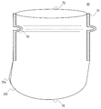
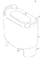
- FIG. 1 schematically shows a mechanism for attaching a valve to a cartridge according to an embodiment. It is a figure which shows roughly the mechanism for attaching a valve to the cartridge which concerns on embodiment. It is a figure which shows schematically another mechanism for attaching a valve to the cartridge which concerns on embodiment. It is a figure which shows schematically another mechanism for attaching a valve to the cartridge which concerns on embodiment. It is a figure which shows schematically another mechanism for attaching a valve to the cartridge which concerns on embodiment. It is a figure which shows schematically another mechanism for attaching a valve to the cartridge which concerns on embodiment. It is a figure which shows schematically another mechanism for attaching a valve to the cartridge which concerns on embodiment. It is a figure which shows schematically another mechanism for attaching a valve to the cartridge which concerns on embodiment.
- FIG. 20A is a view showing a state where stool is stored as filth in the bottom of the valve
- FIG. 20B is a view showing a state where urine is stored in addition to the stool.
- 22A, 22B, 22C, and 22D are diagrams schematically showing the structure of another example of the valve according to the embodiment.
- FIG. 24 (a) and 24 (b) are schematic cross-sectional views showing a state when filth is stored in the cartridge according to the embodiment. It is sectional drawing of the cartridge and toilet device which concern on embodiment.
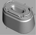
- FIG. 30 is a perspective view of the cartridge shown in FIG. 29 as viewed obliquely from below.
- FIG. 31 is a diagram showing a bottom surface of the cartridge shown in FIG. 30. It is a figure for demonstrating further about the structure of the bottom face of a cartridge.
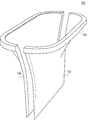
- FIG. 30 is a perspective view of the opposite side surface of the cartridge shown in FIG. 29 as viewed obliquely from above. It is a figure which shows the structure of the seal wall which comprises the valve which concerns on embodiment.
- FIG. 35 is a side view of the valve shown in FIG. 34. It is a figure which shows schematically a mode that the valve shown in FIG. 34 was installed in the cartridge. It is a figure which shows schematically a mode that the valve shown in FIG. 34 was installed in the cartridge.
- valve of the present invention a valve installed between a toilet of a mobile toilet and a cartridge for storing filth will be described. First, the details of the toilet device that can be used as a mobile toilet will be described, and then the details of the valves installed in the toilet device will be described.
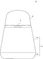
- FIG. 1 is a perspective view of a toilet device 10 according to the embodiment.
- FIG. 2 is a side view of the toilet device 10
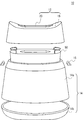
- FIG. 3 is an exploded view of the toilet device 10.
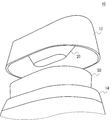
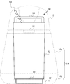
- the toilet device 10 includes a toilet 12 (see FIG. 3) in which a toilet seat 16 for a user to sit on a toilet and a toilet bowl 20 for receiving filth are integrally formed, and a housing 14 that supports the toilet 12. Is provided.
- the toilet bowl 20 is formed with a filth input port through which filth discharged by the user is input at the top and a filth discharge hole at the bottom for discharging the filth.
- the waste discharge hole is configured to be smaller than the waste input port.
- a cartridge 50 for storing filth is detachably attached to the housing 14.
- the housing 14 is provided with a handle 15 for carrying the toilet device 10.
- the cartridge 50 can be protected from moisture, dirt, and the like, and the cartridge is used to discard the stored filth.
- the toilet device 10 can be used by mounting another cartridge 50.
- the opening of the toilet bowl 12 or the opening of the cartridge 50 is opened when passing material such as filth and washing water is introduced, and the passing material is allowed to pass through, and closed at other times so that contents and odors are not discharged to the outside.
- a valve is provided to do this. Therefore, in FIGS. 1 to 3, a lid for closing the opening of the toilet 12 is not provided at the upper part of the toilet 12, but in another example, a lid may be provided at the opening of the toilet 12. Details of the valve will be described later.
- the housing 14 has a frustum shape whose bottom surface is rounded rectangle or ellipse, and can be divided into a body portion 14a and a bottom surface portion 14b.
- the body portion 14a and the bottom surface portion 14b can be stacked separately. The required space can be reduced.
- the housing 14 is divided into the body portion 14a and the bottom surface portion 14b, each can be made independent, so that the body portion 14a and the bottom surface portion b can be stably stacked.
- the combination thereof may be stacked, or the trunk section 14a and the toilet bowl 12 may be stacked separately.
- the handle 15 may be piled up in the state attached to the housing 14, or the handle 15 may be removed from the housing 14 and stored or transported separately. Since the boundary line between the trunk portion 14a and the bottom surface portion 14b is in an inconspicuous position below the toilet device 10, it is also preferable in terms of aesthetics.
- the housing 14 may be divisible into more parts. Since a valve is provided at the opening of the toilet 12 or the opening of the cartridge 50 to prevent leakage of filth and odor stored in the cartridge 50, the housing 14 does not need to have a sealed structure. Therefore, the boundary of the part divided
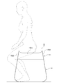
- FIG. 4 is a diagram illustrating an example of a usage state of the toilet device 10.
- the toilet device 10 is used in a state where the housing 14 is placed on the floor surface.
- the user uses the stool while sitting on the toilet seat 16.
- the waste excreted by the user is received by the toilet 12 (not shown), discharged through the toilet 12 to the cartridge in the housing 14, and stored in the cartridge.
- the cleaning water is supplied into the toilet 12 manually by the user.
- the filth here includes both small water and stool.
- the upper surface of the toilet seat 16 there are formed an opening for passing filth and a seating surface 16e for the user to sit on the left and right.
- the upper surface has a long dimension in one direction (the left-right direction in FIG. 4; hereinafter referred to as the front-rear direction) in a plan view, and the other direction orthogonal to the one direction (the depth direction in FIG. It is formed to have an elliptical ring shape with a shorter dimension.
- the upper surface is formed in a curved surface that is convex upward.
- the upper surface is formed such that a gentle downward gradient is provided on the seating surface 16e as it goes from the central side in the left-right direction toward both outer sides.
- the user can easily sit in a posture in which both legs are placed on the left and right sides of the toilet seat 16 after straddling the seating surface 16e on the left and right. From this point of view, it may be formed so as to be convex upward.
- the outer peripheral surface portion 16d is formed to extend downward from the outer peripheral edge of the upper surface portion 16b, that is, from the outer peripheral portion of the upper surface portion 16b, and has a cylindrical shape. Although not shown, the outer peripheral surface portion 16d is formed to have an elliptical ring shape having a long dimension in the front-rear direction and a short dimension in the left-right direction in plan view.
- the upper surface is formed such that the surface portions on both sides in the left-right direction are located below the surface portions on both sides in the front-rear direction.
- the surface portions 16 da on both sides in the left-right direction of the outer peripheral surface portion 16 d are leg support portions that can apply the user's legs (particularly the thighs) when the user sits on the seating surface 16 e. It becomes.
- the leg pad 16da of the outer peripheral surface portion 16d is placed on both legs (in particular, with the soles of the legs on the floor). Can be pinched inside the thigh). Thereby, the direction around the vertical axis of the toilet device 10 can be held by both legs of the user.
- the toilet apparatus 10 As a whole will be difficult to displace so as to swing around the vertical axis, and the user will be seated on the seating surface of the toilet seat 16. It becomes possible to use the stool while sitting stably at 16e.
- at least the outer peripheral surface portion 16d only needs to include the leg pad portion 16da. That is, the surface portions 16db on both sides in the front-rear direction of the outer peripheral surface portion 16d may be omitted.
- the leg pad 16da is formed so as to spread on both outer sides in the left-right direction as it goes downward. Thereby, it becomes easy to apply both legs of a user, and it becomes easy to pinch the leg contact part 16da firmly inside the user's both legs.
- the user first takes a posture of standing on the rear side of the toilet device 10 (right side in FIG. 4) with the front facing the toilet device 10. Thereafter, the user walks forward (left side in FIG. 4) and approaches the toilet device 10, and then places both legs so as to straddle the seating surface 16 e of the toilet seat 16. Sit down on the face 16e.
- the user does not have to walk backward in order to sit on the toilet seat 16.
- the user sits with his / her legs on the leg rest 16da of the toilet seat 16 and rides on the toilet seat 16.
- the user rises up to stand away from the seating surface 16e of the toilet device 10, and then moves away from the toilet device 10 to the front side.
- the toilet seat 16 and the toilet device 10 are configured so that there is no interference on the front and rear sides of the user when the user sits on the seating surface 16e.
- the toilet seat 16 and the toilet device 10 have a structure free of interfering objects so that when the user sits up from the seating surface 16e, the toilet seat 16 and the toilet apparatus 10 can move both before and after the user. Yes.
- the interfering object refers to a portion protruding upward from the toilet seat 16 or the toilet apparatus 10.
- leg pad part 16da you may set the height dimension from the outer peripheral part of the upper surface part 16b to a lower end part to 10 cm or more, for example.
- the upper limit value of the length may be set so as not to hit the floor, but may be set to 50 cm or less, for example.
- the leg pad portion 16da is set so that the height dimension is longer than the left-right dimension of the surface portions on both sides in the left-right direction of the upper surface. Both are configurations from the viewpoint of making it easy to apply both legs of the user to the leg rest 16da.
- the housing 14 is formed in a trapezoidal shape so as to spread on both sides in the left-right direction and both sides in the front-rear direction as it goes downward. Therefore, the housing 14 can be easily placed on the floor surface in a stable state, and the user can easily sit on the seating surface 16e of the toilet seat 16 supported by the housing 14 in a stable state. In addition, there is an effect that the user can easily sandwich the housing 14 with both legs.
- FIG. 5 is an exploded view of the toilet device 10.
- the toilet seat, the side surface, and the toilet bowl are integrally molded by materials, such as synthetic resins, such as polyethylene, for example.
- An opening for discharging filth to the cartridge is provided in the lower part of the toilet bowl 20.
- the opening is provided at substantially the center of the toilet seat.
- the opening may be arranged forward or rearward when the user sits on the toilet seat.
- FIG. 6 is a side view of the cartridge 50.
- the cartridge 50 includes a main body 52 capable of storing dirt therein, a handle 54 that can be gripped by a user when carrying the cartridge 50, and a lid 56 for closing the opening of the main body 52. .
- the cartridge 50 is attached to the housing 14 with the lid 56 open.
- the mounting protrusion 60 provided on the bottom of the cartridge 50 is fitted into the mounting recess 62 provided on the bottom surface inside the housing 14, whereby the cartridge 50 is attached to the housing 14.
- the attachment protrusion 60 may not be provided, and in this case, the cartridge 50 may be attached to the housing 14 by fitting the main body 52 into the attachment recess 62.
- the inside of the toilet 12 is hollow, but the lid 56 is slanted by a hinge or the like at an angle of about 100 ° to 160 ° in the opened state as shown in FIG. Since it is configured to be fixed, it can be stored in the cavity inside the toilet 12. Further, when the toilet 12 is attached to the housing 14, when the toilet 12 is not attached at a normal position and is attached in an inclined state, the lid 56 is caught on the toilet 12, so that the attachment position of the toilet 12 is determined. The user can be made aware that it is wrong.
- the angle of the lid 56 in the opened state may be an angle substantially parallel to the toilet bowl 20, for example.
- the handle 54 is configured to be stored in a cavity inside the toilet 12. Further, the handle 54 and the lid 56 are provided at positions where the lid 56 and the handle 54 do not interfere with each other when the lid 56 is opened.
- the lid 56 may not be fixed to the upper surface of the cartridge 50 by a hinge or the like, and the lid 56 and the cartridge 50 may be configured independently.
- a pocket for storing the lid 56 when the lid 56 is removed may be provided in the toilet 12, the housing 14, the cartridge 50, or the like. For example, a pocket may be provided on the side surface of the cartridge 50.
- FIG. 7 is a perspective view of the cartridge 50 as viewed obliquely from above.
- the handle 54 is provided along the rounded rectangular arc portion on the upper surface of the main body 52. As will be described later, the handle 54 also functions as a fixing portion for fixing the upper and lower cartridges 50 so that the relative positions of the upper and lower cartridges 50 do not shift when another cartridge 50 is stacked on the upper surface of the cartridge 50.
- FIG. 8 is a perspective view of the cartridge 50 as viewed obliquely from below.
- the attachment convex portion 60 is provided along the outer periphery on the lower surface of the main body 52.
- the mounting convex portion 60 is provided slightly inside the outer periphery of the lower surface of the main body 52, and when the mounting convex portion 60 is attached to the housing 14, the mounting convex portion 60 is inserted inside the mounting concave portion 62, and the upper surface of the mounting concave portion 62. Supports the peripheral edge portion of the lower surface of the main body 52.
- FIGS. 9 and 10 are views showing a state where the cartridge 50 is attached to the housing 14.
- the lid 56 is omitted.
- a mounting convex portion 60 is provided on the bottom portion of the main body 52 of the cartridge 50 so that the outer peripheral shape is smaller than that of the other portions.
- the bottom surface on the inner side of the housing 14 matches the shape of the mounting convex portion 60.
- the cartridge 50 is attached to the housing 14 by being inserted into the provided attachment recess 62.
- the mounting convex portion 60 is configured to protrude from the bottom surface of the main body 52, or can be considered to be configured such that the outer peripheral portion of the bottom surface of the main body 52 is removed.
- the mounting recess 62 may be configured by forming a member constituting a wall surface on the outer periphery of the mounting recess 62, or may be configured as a recess on the inner bottom surface of the housing 14.
- the opening at the top of the housing 14 is formed in accordance with the shape of the top of the side surface of the main body 52 of the cartridge 50.
- the cartridge 50 is supported by the housing 14 at both the bottom and top and is stably positioned, so that the position of the cartridge 50 can be prevented from shifting during use.
- the outer periphery of the main body 52 of the cartridge 50 is configured to become slightly smaller as it approaches the bottom, so that the cartridge 50 can be easily inserted into the opening of the housing 14 and inserted deeply.
- the cartridge 50 is gradually positioned at the correct position by the opening of the housing 14, so that the mounting convex portion 60 can be easily fitted into the mounting concave portion 62.
- the user When taking out the cartridge 50 from the housing 14, the user may hold the handle 54 and pull the cartridge 50 upward. As will be described later, since the valve is provided at the opening of the cartridge 50, even when the cartridge 50 is taken out, dirt, odor, etc. stored inside are hardly discharged to the outside. After the cartridge 50 is taken out, the opening can be closed by closing the lid 56.
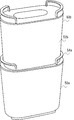
- FIG. 11 is a diagram illustrating a state where the cartridges 50 are stacked.
- the handle 54 is provided along the outer periphery of the upper surface of the main body 52, but the side surface of the main body 52 is configured to be slightly smaller as it approaches the bottom, that is, slightly narrow.
- the bottom of 52 is configured so that the shape just matches the inner periphery of the handle 54. Therefore, when the cartridge 50a and the cartridge 50b are stacked one above the other, the bottom of the main body 52b of the upper cartridge 50b is just inserted between and engaged with the two handles 54a of the lower cartridge 50a.
- the relative position is fixed so as not to shift. That is, the handle 54a is configured to be engageable with the lower portion of the main body 52b of another cartridge 50b. Accordingly, when the cartridge 50 is transported, the plurality of cartridges 50 can be stably stacked and transported.
- FIG. 12 is a perspective view of the upper surface portion 64 of the cartridge 50 as viewed obliquely from below.
- the upper surface portion 64 is configured to be detachable with respect to the main body 52, and a valve mounting portion 66 for mounting the valve 28 is provided along an opening disposed substantially at the center of the upper surface portion 64.
- the valve 28 is attached so as to cover the valve attachment portion 66 from the outside through the upper opening of the valve 28, and the valve 28 is fastened to the inner valve attachment portion 66 from the outside of the valve 28 with an annular fastening member. Fix it.
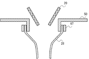
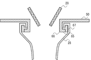
- FIG. 13 and 14 schematically show a mechanism for attaching the valve 28 to the cartridge 50.
- FIG. 13 is a schematic vertical sectional view in the vicinity of the valve mounting portion 66.
- the upper opening of the cartridge 50 is larger than the opening of the toilet bowl 20, and the toilet bowl 20 and the cartridge 50 are installed so that the upper surface of the cartridge 50 cannot be seen when viewed from above. Further, the toilet bowl 20 and the cartridge 50 are installed so that the opening of the toilet bowl 20 is inserted into the opening of the cartridge 50 so that the lower end of the opening section of the toilet bowl 20 is lower than the upper end of the opening section of the cartridge 50. . Thereby, it is possible to prevent the upper surface of the cartridge 50 from being soiled by the filth introduced from the toilet bowl 20 into the cartridge 50.
- valve 28 is fastened by a fixing member 67 from the outside of the valve mounting portion 66 provided on the lower side of the upper surface portion of the cartridge 50, and is fixed to the valve mounting portion 66.
- the valve mounting portion 66 may be provided with a locking portion 65 for locking the upper end of the valve 28, and the upper end of the valve 28 may be locked to the locking portion 65.
- FIG. 15 schematically illustrates another mechanism for attaching the valve 28 to the cartridge 50.
- a fixing member 67 constituted by a rubber band or a spring is attached to the inside of the upper end of the valve 28, and the valve 28 is a valve attachment portion 66 provided below the upper surface portion of the cartridge 50. It is fastened inward by a fixing member 67 from the outside of the locking portion 65 and is fixed to the valve mounting portion 66.
- the valve 28 attached with the fixing member 67 may be supplied as a replacement so that the valve 28 and the fixing member 67 can be replaced at the same time.
- FIG. 16 schematically illustrates another mechanism for attaching the valve 28 to the cartridge 50.
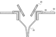
- a valve mounting portion 68 for locking the valve 28 is provided above the upper surface portion of the cartridge 50, and the upper end of the valve 28 is locked to the valve mounting portion 68.
- FIG. 17 schematically illustrates yet another mechanism for attaching the valve 28 to the cartridge 50.
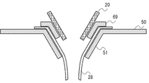
- the upper end of the valve 28 is locked to the valve mounting portion 68 provided on the upper side of the upper surface portion of the cartridge 50 as in the example of FIG. 51 is made parallel to the toilet bowl 20 instead of vertical.
- the gap between the toilet bowl 20 and the cartridge 50 can be further narrowed, so that liquid such as small water or washing water bounces back into the gap between the toilet bowl 20 and the cartridge 50, and the upper surface of the cartridge 50. Etc. can be prevented from getting dirty.
- the valve 28 can be attached and detached without removing the upper surface portion of the cartridge 50, the convenience for the user can be improved.
- FIG. 18 schematically illustrates yet another mechanism for attaching the valve 28 to the cartridge 50.
- the folding surface 51 at the periphery of the opening of the cartridge 50 is not vertical but parallel to the toilet bowl 20.
- the valve 28 is fixed to the upper surface of the cartridge 50 by pressing the upper end of the valve 28 against the upper surface and the folding surface 51 of the cartridge 50 from above with a fixing member 69 that is matched to the shape of the opening. To do.
- This also makes it possible to further narrow the gap between the toilet bowl 20 and the cartridge 50, so that liquid such as small water or washing water bounces back and enters the gap between the toilet bowl 20 and the cartridge 50. It is possible to prevent the upper surface and the like from becoming dirty. Further, since the valve 28 can be attached and detached without removing the upper surface portion of the cartridge 50, the convenience for the user can be improved.
- valve 28 is described as being attached to the cartridge 50. However, when the valve 28 is attached to the toilet bowl 20, or as will be described later, the valve 28 is attached to an opening of a container or the like other than the toilet device. The valve 28 can be attached to the opening as in the above example.
- FIG. 19 is a diagram schematically showing the configuration of the valve 28.
- the valve 28 is configured by a pair of seal walls 32a and 32b (both are collectively referred to as a seal wall 32) that are arranged so that the inner side surfaces thereof face each other on the left and right.
- Each seal wall 32 is formed of a material having flexibility and stretchability. In the present embodiment, silicon rubber is used as a flexible material. Silicone rubber is also a material that is durable and hydrophilic to dirt caused by dirt.
- Each seal wall 32 is bonded at the upper bonding portion 70 at both ends, and the uppermost portion constitutes a supported portion 72 to be attached to the valve attachment portion 66.
- a member formed of a synthetic resin or the like according to the shape of the valve mounting portion 66 may be bonded to the valve 28.
- the valve 28 can be easily attached to the valve attachment portion 66.
- the lower portions of the seal walls 32 are separated without being bonded, and slit-like filth discharge holes 26 are formed therein.
- each seal wall 32 is not mutually adhere
- attached when using the toilet device 10, since the small water as a waste, washing water, etc. will pass the inner side of the valve 28, the lower part of each seal wall 32 is used.
- their inner side surfaces are in close contact with each other due to the surface tension of water.
- the filth discharge hole 26 can be closed, and the odor due to the filth in the cartridge 50 can be prevented from leaking from the filth discharge hole 26 to the outside.
- the inside of the cartridge 50 located behind the filth discharge hole 26 can be prevented from being seen from the opening of the toilet 12, so that the user can comfortably place the toilet apparatus 10 in the toilet 50. Can be used.
- FIG. 20 is a diagram for explaining the operation of the valve 28.
- FIG. 20A shows a state where stool Pa is stored as filth in the bottom of the valve 28, and
- FIG. 20B shows a state where urine Pb is stored in addition to the stool Pa.
- the pair of seal walls 32 is provided with a closing force Fb that closes the filth discharge hole 26 by the surface tension caused by the water between the seal walls 32 and its own elastic repulsion.
- the closing force Fb restores the shape of the pair of seal walls 32 so as to narrow the inner width of the filth discharge hole 26, and the filth discharge hole 26 is closed.
- the valve structure formed by the pair of seal walls 32 can open the filth discharge hole 26 by the weight of the object stored in the bottom of the valve 28.
- the pair of seal walls 32 can be opened by the weight of only the filth and the filth can be discharged.
- the weight of the filth may be insufficient.
- the filth may be discharged by directly supplying cleaning water from a bottle or the like.
- the pair of seal walls 32 is configured to open when 10 to 100 g of cleaning water is input from the viewpoint of reducing the amount of cleaning water used. May be.
- the thickness, hardness, and the like of each seal wall 32 may be adjusted.
- silicon rubber having a hardness of 0 to 20 °, more preferably a hardness of 0 to 10 ° may be used.
- FIG. 21 and 22 are diagrams schematically showing the structure of another example of the valve 80.
- the sealing wall 32 is lifted from the same side at the lifted positions 82 at both ends of the sealing wall 32 so that the sealing wall 32 is vertically moved. It is bent and pinched so that the inner surface of 32 abuts.
- the seal wall 32 may be pinched with a clip or the like, or may be fixed with staples or the like in the pinched state. Both ends of each seal wall 32 are lifted upward, but the vicinity of the center bends due to its own weight. Therefore, the filth discharge hole 26 at the lower end is curved in a curved shape with both ends being high and the vicinity of the center being low.
- FIG. 22 (a) is a side view of the valve 28 shown in FIG. 19, and FIG. 22 (b) is a side view of the valve 80 shown in FIG.
- each seal wall 32 forms a plane parallel to the vertical surface.
- each seal wall 32 is pulled upward at the lifted position 82, so that the seal below the lifted position 82 is sealed.
- the wall 32 curves to the opposite side of the pinched direction, and becomes a convex curve toward the pinched direction in a side view, and the filth discharge hole 26 at the lower end is lifted slightly upward.
- each seal wall 32 is a straight line parallel to the long axis of the opening of the cartridge 50 in a plan view when the valve 28 is attached to the cartridge 50, but in the valve 80, as described above.
- the seal wall 32 below the lifting position 82 is curved to the opposite side of the pinched one, and the degree of the curve is larger at the pinched position, that is, at both ends than near the center.
- the seal wall 32 has a curved curve that is convex in a pinched direction in a plan view when the valve 28 is attached to the cartridge 50.
- each seal wall 32 has a curved shape that protrudes in the horizontal direction or obliquely downward on the pinched side in the region below the lifting position 82 including at least the lower end. Since the closing force between the walls 32 is close to that of the valve 28, the sealing walls 32 are in close contact with each other and are easily closed even after the filth passes and is opened, and the filth discharge hole 26 is not closed. The situation of being kept open can be reduced.
- FIG. 23 is a reference photograph of an example of the valve 80 shown in FIG.
- the front side of the paper at both ends of the upper part of the seal wall 32 is picked up, and the lower part of the seal wall 32 has a curved surface shape that protrudes obliquely downward on the front side of the paper.
- the lower end of the seal wall 32 has a curved shape with both ends being high and the vicinity of the center being low.
- FIG. 24 is a schematic cross-sectional view showing a state where filth is stored in the cartridge 50.
- liquids such as small water and washing water are more than solids, so some solids float in the liquid, and some The solids are sinking.
- the sealing wall 32 is pushed up by the liquid level as shown in FIG. If it continues to be used in this state, the filth that could not pass through the filth discharge hole 26 accumulates in the valve 28, and odor leaks from the opening of the cartridge 50. Therefore, a mechanism is required to make the user aware that the storage state of the filth in the cartridge 50 reaches the upper limit and the filth must be discarded or the empty cartridge 50 needs to be replaced.
- the sealing wall 32 may be formed of a transparent or translucent material that transmits at least part of visible light, and the storage state of the filth may be recognized by a color change. Further, a mark or an image indicating that the storage state of the filth has reached the upper limit is provided at a position inside or outside the seal wall 32 where the seal wall 32 can be visually recognized from above when pushed up by the filth. May be. When this mark is provided inside the seal wall 32, the seal wall 32 may be made of an opaque material. When this mark is provided outside the seal wall 32, the seal wall 32 is made of a transparent or translucent material.
- the valve 80 since the valve 80 has flexibility, it has the following advantages.
- the filth introduced into the valve 80 stops on a part of the inner surface without being guided to the entrance of the filth discharge hole 26 at the bottom.
- the other portion is flexed and deformed, so that the portion on which the filth is placed easily follows and deforms.
- the filth that has stopped at a part of the valve 80 is easy to move, and the filth is easily guided to the bottom of the valve 80.
- valve 80 since the valve 80 has flexibility, the entire valve 80 can be vibrated when washing water or the like is poured into the toilet bowl 20 to flow filth or when it rises from the toilet seat 16 of the toilet device 10. it can. In particular, since the valve 80 is hung from the cartridge 50, the entire valve 80 is particularly easily vibrated. This vibration makes it easier for the filth in the valve 80 to move, and also from this point it is easier to guide the filth to the bottom of the valve 80.
- the filth in the valve 80 is easily discharged from the filth discharge hole 26 at the bottom of the valve 80.
- the toilet device 10 suitable for use in an environment where the water supply cannot be used can be provided.
- valve 80 since the valve 80 has flexibility, it becomes difficult to repel when the valve 80 receives filth, particularly urine. Therefore, it is possible to prevent the filth from splashing back and splashing around and hitting the user.
- valve 80 is constituted by a pair of seal walls 32 that open and close the filth discharge hole 26 by contacting and separating the inner side surfaces of each other, the valve 80 can be realized with a simple structure, and the manufacturing cost is reduced. be able to.
- the pair of seal walls 32 since the pair of seal walls 32 is constituted by the separated sheet bodies, the pair of seal walls 32 can move greatly without restricting movement of each other. Therefore, the opening when the pair of seal walls 32 is opened can be increased, and a large amount of waste can be discharged early.
- seal wall 32 is made of silicon rubber.
- any material having flexibility may be used, and for example, a synthetic resin such as a fluorine resin or an olefin resin may be used.
- the housing 14 has been described as an example of a support that supports the toilet 12.
- the support may not be portable with the toilet 12 such as the housing 14.
- the support may be a fixed structure such as the floor of a flush toilet.
- valve 80 is detachably attached to the cartridge 50.
- the valve 80 may be detachably attached to the toilet 12 or the housing 14.
- At least one of the pair of seal walls is in contact with the inner surface of the seal wall in the vertical direction in the vicinity of both ends of the pair of seal walls. It may be fixed in a state where it is bent and pinched on the same side. According to this aspect, the valve can be realized with a simple structure, and the manufacturing cost can be reduced.
- At least one of the pair of seal walls may be lifted upward at a position where both ends are bonded to each other. According to this aspect, it is possible to obtain a structure in which an object is not easily clogged inside the valve and the lower end is easily adhered after the object passes.
- the upper ends of the pair of seal walls may be fixed in an open state. According to this aspect, even if the valve is used in a state where the upper end is always opened, a structure in which the lower end can be easily adhered can be obtained.
- the pair of seal walls may be flexible. According to this aspect, since the seal wall is easily elastically deformed when an object passes through the valve, the object can easily pass through the valve quickly.
- the pair of seal walls may be made of silicon rubber having a hardness of 0 to 20 °. According to this aspect, while using silicon rubber having excellent durability, the seal wall can be easily elastically deformed, and an object can easily pass through the valve quickly.
- FIG. 25 and 26 are cross-sectional views of the cartridge 50 and the toilet device 10, and FIG. 27 is an exploded view of the cartridge 50 and the toilet device 10.
- FIG. 25 is a cross-sectional view taken along a plane parallel to the longitudinal direction of the upper surface of the cartridge 50
- FIG. 26 is a cross-sectional view taken along a plane parallel to the lateral direction of the upper surface of the cartridge 50.
- the bottom surface 100 of the cartridge 50 includes a flat planar region 102 including the vicinity of the center (center of gravity or center) of the bottom surface 100, and a slanted first sloping region 104 and a second sloping region between the planar region 102 and the side surface of the cartridge 50. 106.
- the first inclined region 104 and the second inclined region 106 are inclined so as to become lower toward the center, and the inclination angle in the first inclined region 104 closer to the inside, that is, the one closer to the planar region 102 is The inclination angle is larger than that of the second inclined region 106 on the outer side, that is, the side closer to the side surface of the cartridge 50.
- the filth sinking on the bottom surface 100 tends to gather around the center by rolling down the slope, so that it is efficient even when the nozzle is inserted into the cartridge 50 and the filth is sucked from the cartridge 50 without moving the nozzle position. It can suck filth well. Further, by making the inclination angle in the second inclination area 106 smaller than the inclination angle in the first inclination area 104, the capacity inside the cartridge 50 can be increased as compared with the case where it is not.
- the tilt angle in the first tilt region 104 may be constant, or may be changed so that the tilt angle is larger or smaller on the inner side.
- the tilt angle in the second tilt region 106 may be constant, or may be changed so that the tilt angle is larger or smaller on the inner side.
- the first inclined region 104 and the second inclined region 106 may be connected smoothly so that the inclination angle changes continuously, or may be connected so that the inclination angle changes discontinuously. Good.
- the first inclined region 104 and the planar region 102 may be connected smoothly so that the inclination angle changes continuously, or connected so that the inclination angle changes discontinuously. Also good.
- the shape of the outer periphery of the first inclined region 104 may be circular in plan view, may be similar to the upper surface of the cartridge 50 and smaller than the upper surface of the cartridge 50, or may be It may be a rounded rectangle or an ellipse with the longitudinal direction as the major axis. Further, the shape of the outer periphery of the first inclined region 104 may be a square, a rectangle, or a polygon such as a trapezoid in a plan view. Similarly, the shape of the outer periphery of the planar region 102 may be a circle, a polygon, a rounded rectangle, an ellipse, or the like in plan view.
- the first inclined region 104 and the planar region 102 may be formed in a mortar shape or a groove shape. Note that the planar region 102 may not be formed, and in this case, the first inclined region 104 may be formed in a curved surface shape such as a spherical surface, an oblate spherical surface, and an oblong spherical surface including the vicinity of the center of the bottom surface 100.
- the inclination angle in the first inclined area 104 and the second inclined area 106 may be isotropic or anisotropic.
- the first inclined region 104 and the second inclined region 106 may be formed in a mortar shape with an isotropic angle.
- region 104 is formed in a rounded rectangle, a rectangle, or an ellipse in planar view, the inclination angle which differs in a longitudinal direction and a transversal direction may be given.
- the inclination angle in the short direction is made larger than the inclination angle in the longitudinal direction
- the inclination angle in the longitudinal direction is made larger than the inclination angle in the short direction. Also good.
- the tilt angle in the first tilt region 104 or the second tilt region 106 is foreign, it is sufficient that the maximum tilt angle in the first tilt region 104 is larger than the maximum tilt angle in the second tilt region 106.
- the stored filth is extracted and the inside is cleaned and reused.
- a small amount of liquid 110 may be put into the cartridge 50. .
- the liquid 110 may contain, for example, an antibacterial agent, a deodorizing agent, a fragrance, and the like, thereby preventing bacterial growth and odor.
- the liquid 110 can be concentrated on the flat area 102 near the center where the filth easily falls by providing the first inclined area 104, so that the necessary effect is maintained while maintaining the above effect. The amount of the liquid 110 can be reduced, and the capacity of the cartridge 50 can be used effectively.
- a cushioning material 120 for alleviating the impact is provided on the bottom surface portion 14b of the housing 14 of the toilet device 10 at a position where the bottom surface of the cartridge 50 abuts.
- a cushioning material 122 is also provided at a position where the upper portion of the cartridge 50 abuts on the upper portion of the body portion 14 a of the housing 14. Thereby, stability when the cartridge 50 is installed in the housing 14 can be improved, and generation of sound due to rattling can be suppressed.
- the handle 15 is detachably provided on the housing 14 as shown in FIG. 3.
- the housing 14 is provided integrally.
- the lid 56 is fixed to the upper surface of the cartridge 50 by a hinge or the like.
- the cartridge 50 shown in this figure is provided with a storage portion 130 for storing the lid 56 on the side surface.
- the lid 56 of the cartridge 50 can be removed and stored in the storage unit 130.
- FIGS. 6 and 13 to 18 when the toilet 12 is installed on the housing 14, the lower end of the opening portion of the toilet bowl 20 is lower than the upper end of the opening portion of the cartridge 50. Therefore, the toilet 12 cannot be installed on the housing 14 in a state where the lid 56 is closed. Thereby, it is possible to prevent the toilet device 12 from being used by accidentally installing the toilet device 12 with the lid 56 closed.
- the planar region 102 and the first inclined region 104 of the bottom surface 100 of the cartridge 50 have a rounded rectangular shape in plan view, and are formed in a groove shape as a whole.
- FIG. 28 is a perspective view of the toilet device 10 shown in FIG.
- the storage portion 130 is provided so that the opening of the pocket is slightly larger than the side surface of the lid 56 so that the lid 56 can be easily inserted into and removed from the pocket.
- the storage unit 130 is provided so that the depth of the pocket is slightly shallower than the length of the lid 56 in the short direction.
- FIG. 29 shows still another example of the cartridge 50.
- the bottom surface 100 is inclined similarly to the cartridge 50 shown in FIGS.
- the cartridge 50 shown in this figure is provided with legs 140 near the outer periphery of the bottom surface 100.
- the two legs 140 are provided in the rounded rectangular arc portion that forms the outer periphery of the bottom surface 100, but, similar to the mounting convex portion 60 of the cartridge 50 shown in FIGS.
- One leg may be provided along the entire outer periphery of the bottom surface 100, or four legs may be provided at the four corners of the bottom surface 100.
- the cartridge 50 shown in this figure is configured such that the leg 140 just matches the inner periphery of the handle 54, and the cartridge 50 a and the cartridge 50 b are stacked one above the other. At this time, the bottom portion of the main body 52b of the upper cartridge 50b is just inserted between the two handles 54a of the lower cartridge 50a, and is fixed so that the horizontal relative position between the cartridges does not shift. Accordingly, when the cartridge 50 is transported, the plurality of cartridges 50 can be stably stacked and transported.
- FIG. 30 is a perspective view of the cartridge 50 shown in FIG. 29 as viewed obliquely from below.
- FIG. 31 shows the bottom surface 100 of the cartridge 50 shown in FIG.
- the bottom surface 100 of the cartridge 50 includes a planar region 102, a first inclined region 104, and a second inclined region 106, and the outer periphery of the planar region 102 and the first inclined region 104 is formed to be substantially circular in plan view.
- the planar region 102 and the first inclined region 104 constitute a truncated cone that is inverted in the vertical direction.
- the diameter of the outer periphery of the first inclined region 104 is preferably larger than the diameter of the nozzle. As a result, the nozzle can be inserted into the truncated cone formed by the first inclined region 104 to suck the filth. Moreover, it is preferable that the outer periphery of the 1st inclination area
- the diameter of the outer periphery of the planar region 102 may be larger or smaller than the nozzle diameter.
- FIG. 32 is a diagram for further explaining the structure of the bottom surface 100 of the cartridge 50.
- the position A near the end of the long axis is farther from the first inclined region 104 and the flat region 102 near the center than the position B near the end of the short axis. Therefore, when sucking filth by inserting a nozzle in the vicinity of the flat area 102, if the inclination of the second inclined area 106 is made isotropic, the vicinity of the position B among the solid matter riding on the second inclined area 106 However, it is conceivable that those near the position A are left without being dropped to the first inclined area 104 even if the liquid level is lowered.
- the inclination angle between the position A and the position A ′ near the end of the long axis of the first inclined region 104 is set to the end of the short axis of the position B and the first inclined region 104. It is made larger than the inclination angle with the position B ′ near the portion.
- the second inclined region 106 of the bottom surface 100 is configured so that the position B is lower than the position A. Accordingly, when the nozzle is inserted in the vicinity of the flat area 102 and the filth is sucked, the solid matter near the position A far from the first inclined area 104 is located at the position A when the liquid level is near the height of the position A.
- the solid matter in the vicinity of the position B close to the first inclined area 104 is moved to the position B ′ until the liquid level becomes near the height of the position B. Therefore, it is possible to easily stay in the spot without falling, so that it is possible to reduce a situation in which solid matter is left in the vicinity of the position A.
- the inclination angle is larger than that of the second inclined region 106 in both the major axis direction and the minor axis direction, so that the solid matter that is sinking without floating in the liquid is sucked. Accordingly, it can be efficiently dropped onto the planar region 102.
- the inclination angle at each position may be B ′ ⁇ A ′>A> B.
- the valve structure since the length in the major axis direction of the valve is shorter than the length in the major axis direction of the bottom surface 100 of the cartridge 50, the solid matter that has passed through the valve does not fall near the position A. Therefore, when the liquid level is lower than the height of the position A, the situation where the solid substance reaches the vicinity of the position A can be suppressed by the valve structure. With the above configuration, when the filth is sucked, the liquid and solid filth can be easily sucked to the flat region 102, so that the situation in which the filth is left on the bottom surface 100 can be remarkably reduced.
- FIG. 33 is a perspective view of the opposite side surface of the cartridge 50 shown in FIG. 29 as viewed obliquely from above.
- the cartridge 50 shown in this figure is provided with a storage portion 130 for storing the lid 56 in the upper part of the main body 52. And a support portion 132 for supporting the lid 56 stored in the storage portion 130.
- the lid 56 can be stored and held in the storage portion 130, so that the filth stored in the cartridge 50 is sucked to wash the cartridge 50. At this time, the lid 56 can be stored so as not to be lost.
- the cushioning material 122 may not be provided at a position where the support portion 132 hits when the cartridge 50 is installed in the housing 14, and the support portion 132 is supported.
- the buffer material 122 may be provided so that the part 132 does not hit.
- FIG. 34 shows the structure of the seal wall constituting the valve.
- the valve 28 shown in FIG. 19 and the valve 80 shown in FIG. 21 are configured by bonding a pair of planar sealing walls 32 together.
- the valve 150 shown in FIG. A pair of sealing walls 152 formed in a three-dimensional manner is attached to each other.
- the seal wall 152 is also formed of silicon rubber.
- a locking portion 154 for locking the valve 150 to a valve mounting portion 160 provided at the opening of the cartridge 50 is provided at the upper end of the seal wall 152.
- Adhesive portions 156 for adhering the two seal walls 152 to each other are provided at the left and right ends of the seal wall 152, and the valve 150 is formed by adhering the adhesive portion 156 with an adhesive or the like.
- FIG. 35 shows how the valve shown in FIG. 34 is installed in the cartridge.
- a valve mounting portion 160 is provided at the opening of the cartridge 50, and the valve 150 is mounted on the cartridge 50 by locking the locking portion 154 of the valve 150 to the valve mounting portion 160.
- a notch 162 is provided at the end of the long axis of the opening of the cartridge 50 in the valve mounting portion 160, and when the valve 150 is locked to the valve mounting portion 160, the upper end of the adhesive portion 156 is notched. 162. Thereby, the valve 150 can be fixed so as not to shift.
- FIG. 36 is a side view of the valve shown in FIG.
- the seal wall 152 constituting the valve 150 includes a first region 170 that is three-dimensionally formed so as to gradually narrow downward from the opening of the cartridge 50, and a lower end of the seal wall 152 below the first region 170.
- a planar second region 172 formed to include The second region 172 includes a second a region 174 near the center and second b regions 176 near both ends.
- the thickness of the seal wall 152 in the first region 170 is thicker than the thickness of the seal wall 152 in the second region 172.
- the first region 170 and the second region 172 may be integrally formed.
- the seal wall 152 may be integrally formed using a mold or the like.
- the surface of the silicon rubber is subjected to a textured surface to give fine irregularities, and in the 2b region 176, the surface is not subjected to a textured process.
- the valve 150 can be easily opened by reducing the area where the seal walls 152 adhere to each other.
- the valve 150 can be easily adhered by increasing the area where the seal walls 152 adhere to each other.
- the surface of the seal wall 152 may be coated with a chemical substance having a small friction coefficient such as polytetrafluoroethylene (Teflon (registered trademark)).
- Teflon polytetrafluoroethylene
- the static frictional force and the dynamic frictional force generated between the surface of the seal wall 152 and the filth can be reduced, and the filth can easily pass through the valve.
- the surface of the seal wall 152 may be coated. Thereby, the discharge
- FIG. 37 schematically shows how the valve shown in FIG. 34 is installed in the cartridge.
- the valve 150 is preferably installed so that stress is applied in the direction in which the valve 150 is closed at the lower part of the valve 150.
- the present inventors have shown not only the case where both ends of the seal wall 32 are lifted upward at the lifting positions 82 of the adhesive portions 70 at both ends of the seal wall 32, as shown in FIG. 21.
- the valve 150 is installed at the upper end of the seal wall 152 so that both ends are higher than the vicinity of the center, the valve 150 is closed under the seal wall 152 due to the tension generated by the weight of the seal wall 152. It has become clear that stress is applied to.
- the valve 150 can be closed more reliably, it is possible to reduce a situation in which the valve 150 is not closed after the filth passes, and to prevent odor leakage.
- the opening of the cartridge 50 is provided so as to be inclined so that it is high at the long-axis end 164 and low at the short-axis end 166, and the valve 150 May be locked to the opening of the cartridge 50 only near the end 164 of the long axis.
- the long-axis end 164 of the opening of the cartridge 50 may be provided so as to be inclined toward the center of the opening. Thereby, the stress concerning the lower part of the seal wall 152 can be enlarged more.
- FIG. 38 schematically shows that the valve shown in FIG. 34 is installed in the cartridge.
- a protrusion 158 that protrudes inward is provided at the upper end of the seal wall 152.
- valve according to the present embodiment is used for an opening of a container for storing a storage of food, beverage, medicine, etc., a pipe for passing a gas, a liquid, a solid, etc. Can be widely used in the case where the reverse flow should be prevented.
- the upper ends of the pair of seal walls may be installed so that the vicinity of the center is higher than both ends.
- the valve can be installed in the lower part of the valve so that the stress is applied in the direction in which the valve is closed. Therefore, the valve can be closed more reliably, and the valve remains open after the passing material passes. The situation where it does not close can be reduced.
- the thickness of the first region may be thicker than the thickness of the second region.
- the strength that can withstand the passage of the passing material is ensured, and the stability of the shape is maintained, while the flexibility is increased in the lower part of the valve so that the passing material passes. At the same time, it can be easily opened, and after the passing material has passed, it can be easily adhered to each other.
- the valve of the above aspect may have irregularities on the surface. According to this aspect, the valve can be easily opened by reducing the area where the seal walls adhere to each other in the upper part of the valve, and the area where the seal walls adhere to each other in the lower part of the valve. Thus, the valve can be easily adhered.
- At least a part near the center of the second region may have unevenness on the surface.
- the valve in the region near the center where the passing material mainly passes, by reducing the area where the seal walls adhere to each other, the valve can be easily opened, and the vicinity of the end where the passing material does not pass so much. In this region, the valve can be easily adhered by increasing the area where the seal walls adhere to each other.
- the first region may have a three-dimensional shape such that the upper end portion has a shape that matches the opening in which the valve is installed, and the first region narrows downward.
- the valve can be shaped according to the opening, and the passing material can be easily passed.
- the first region and the second region may be formed integrally. According to this aspect, the shape stability of the valve can be improved.
- the present invention can be used for a valve for controlling the passage of gas, liquid or solid.
Landscapes
- Engineering & Computer Science (AREA)
- General Engineering & Computer Science (AREA)
- Mechanical Engineering (AREA)
- Non-Flushing Toilets (AREA)
- Sanitary Device For Flush Toilet (AREA)
- Check Valves (AREA)
Abstract
弁150は、互いの内側面が対向して配置され、互いの内側面が接離することにより下端部分を開閉することが可能な一対のシール壁152を含む。一対のシール壁152は、少なくとも上方の一部において、両端付近が互いに接着される。一対のシール壁152は、それぞれ、上部の第1領域と、第1領域よりも下方で下端を含む第2領域とを少なくとも含む。第1領域及び第2領域は、いずれも可とう性部材により形成される。
Description
本発明は、気体、液体又は固体の通過を制御するための弁に関する。
従来より、ポータブルトイレ、簡易水洗式トイレのような便器装置が提案されている。このような便器装置は、水道インフラが整備されていない新興国、地域のような、下水道が使えない環境下での使用に適したものとして用いられている。
たとえば、特許文献1には、弾性変形可能な封止筒を用いた簡易水洗便器が開示されている。封止筒は便器の排便口の直下に取り付けられ、封止筒内に貯まる汚物の重量によって排便口を開閉可能な構造をもつ。これにより、便器の排便口より奥側にある便槽からの臭気の逆流が防止できる。
ところで、ポータブルトイレや簡易水洗式トイレが使用される環境下では、下水道の他に上水道も使えない場合が多い。このような環境下での使い勝手をよくするうえでは、小水や洗浄水などの液体と大便などの固体を含む汚物が投入されたときには通過させ、それ以外のときには外部に漏れないように密閉することを可能とする弁の構造の提案が望まれる。この観点から検討すると、特許文献1の便器では特別の工夫がなされていない。
本発明は、このような課題に鑑みてなされ、その目的は、簡易な構造で気体、液体又は固体の通過を制御することが可能な弁を提供することにある。
上記課題を解決するために、本発明のある態様の弁は、互いの内側面が対向して配置され、互いの内側面が接離することにより下端部分を開閉することが可能な一対のシール壁を含む。一対のシール壁は、少なくとも上方の一部において、両端付近が互いに接着され、一対のシール壁は、それぞれ、上部の第1領域と、第1領域よりも下方で下端を含む第2領域とを少なくとも含む。第1領域及び第2領域は、いずれも可とう性部材により形成される。
この態様によると、可とう性部材を用いた簡易で安価な構成により、通過物を通過させる必要があるときには容易に開いて通過物を通過させ、必要のないときには容易に閉じて密着し、臭気などを逆流させない画期的な弁を提供することができる。
本発明によれば簡易な構造で気体、液体又は固体の通過を制御することが可能な弁を提供できる。
本発明の弁の一例として、モバイルトイレの便器と汚物を貯留するためのカートリッジとの間に設置される弁について説明する。まず、モバイルトイレとして使用可能な便器装置の詳細について説明し、つづいて、その便器装置に設置される弁の詳細について説明する。
以下、実施形態、変形例では、同一の構成要素に同一の符号を付し、重複する説明を省略する。また、各図面では、説明の便宜のため、構成要素の一部を適宜省略する。
[便器装置]
図1は実施形態に係る便器装置10の斜視図である。図2は便器装置10の側面図であり、図3は便器装置10の分解図である。
便器装置10は、使用者が用便の際に座るための便座16と汚物を受けるための便鉢20とが一体成形された便器12(図3参照)と、便器12を支持するハウジング14とを備える。便鉢20には、使用者が排泄した汚物が投入される汚物投入口が上部に形成されるとともに、汚物を排出するための汚物排出孔が底部に形成される。汚物排出孔が汚物投入口よりも小さくなるように構成される。ハウジング14の内部には、汚物を貯留するためのカートリッジ50が、ハウジング14に対して着脱可能に設けられる。ハウジング14には、便器装置10を持ち運ぶための取っ手15が設けられているが、後述するように、カートリッジ50に貯留された汚物を廃棄する際には、カートリッジ50のみを取り外して持ち運ぶことができるので、便器装置10全体を持ち運ぶ必要はない。このような構成とすることにより、便器装置10を浴室などに設置する場合であっても、内部のカートリッジ50を水分や汚れなどから保護することができ、貯留された汚物を廃棄するためにカートリッジ50を運搬する際に、カートリッジ50の表面から使用者の体や衣服に水分や汚れなどが付着することを防ぐことができる。また、汚物の廃棄のためにカートリッジ50を運搬している間も、別のカートリッジ50を装着することにより、便器装置10を使用することができる。
図1は実施形態に係る便器装置10の斜視図である。図2は便器装置10の側面図であり、図3は便器装置10の分解図である。
便器装置10は、使用者が用便の際に座るための便座16と汚物を受けるための便鉢20とが一体成形された便器12(図3参照)と、便器12を支持するハウジング14とを備える。便鉢20には、使用者が排泄した汚物が投入される汚物投入口が上部に形成されるとともに、汚物を排出するための汚物排出孔が底部に形成される。汚物排出孔が汚物投入口よりも小さくなるように構成される。ハウジング14の内部には、汚物を貯留するためのカートリッジ50が、ハウジング14に対して着脱可能に設けられる。ハウジング14には、便器装置10を持ち運ぶための取っ手15が設けられているが、後述するように、カートリッジ50に貯留された汚物を廃棄する際には、カートリッジ50のみを取り外して持ち運ぶことができるので、便器装置10全体を持ち運ぶ必要はない。このような構成とすることにより、便器装置10を浴室などに設置する場合であっても、内部のカートリッジ50を水分や汚れなどから保護することができ、貯留された汚物を廃棄するためにカートリッジ50を運搬する際に、カートリッジ50の表面から使用者の体や衣服に水分や汚れなどが付着することを防ぐことができる。また、汚物の廃棄のためにカートリッジ50を運搬している間も、別のカートリッジ50を装着することにより、便器装置10を使用することができる。
便器12の開口又はカートリッジ50の開口には、汚物や洗浄水などの通過物が投入されたときには開いて通過物を通過させ、それ以外のときには閉じて内容物や臭気が外部に排出されないようにするための弁が設けられる。そのため、図1~3においては、便器12の上部に、便器12の開口を閉じるための蓋が設けられていないが、別の例においては、便器12の開口に蓋が設けられてもよい。弁の詳細については後述する。
図3に示すように、ハウジング14は、底面が角丸長方形又は楕円形である錐台状の形状を有し、胴部14aと底面部14bとに分割可能である。これにより、便器装置10を製造地から使用地に運搬する際や、災害時などのために倉庫などに保管しておく際に、胴部14aと底面部14bとを別々に積み上げることができるので、必要なスペースを小さくすることができる。また、ハウジング14を胴部14aと底面部14bに分割すると、それぞれを自立させることができるので、胴部14aと底面部bを安定的に積み上げることができる。胴部14aの上方に便器12が乗せられた状態で、それらの組み合わせが積み上げられてもよいし、胴部14aと便器12とが別々に積み上げられてもよい。また、取っ手15がハウジング14に取り付けられた状態で積み上げられてもよいし、取っ手15はハウジング14から外され、別途保管又は運搬されてもよい。胴部14aと底面部14bとの境界線が、便器装置10の下方の目立たない位置にあるので、美感の面でも好ましい。別の例においては、ハウジング14は更に多くの部分に分割可能であってもよい。便器12の開口又はカートリッジ50の開口に弁が設けられ、カートリッジ50内に貯留される汚物や臭気の漏洩が防止されるので、ハウジング14を密封構造とする必要はない。したがって、複数に分割された部分の境界は、密封構造でなくてもよい。
図4は便器装置10の使用状態の一例を示す図である。
便器装置10はハウジング14を床面上に載せた状態で用いられる。使用者は便座16上に座った状態で用便する。使用者が排泄した汚物は便器12(不図示)により受けられ、便器12内を通してハウジング14内のカートリッジに排出され、カートリッジ内に貯められる。便器12内への洗浄水の供給は使用者の手作業で行う。使用者は、ボトル、ホース等から便器12内に洗浄水を投入することで便器12内を洗浄する。なお、ここでの汚物には、小水と大便の両方が含まれる。
便器装置10はハウジング14を床面上に載せた状態で用いられる。使用者は便座16上に座った状態で用便する。使用者が排泄した汚物は便器12(不図示)により受けられ、便器12内を通してハウジング14内のカートリッジに排出され、カートリッジ内に貯められる。便器12内への洗浄水の供給は使用者の手作業で行う。使用者は、ボトル、ホース等から便器12内に洗浄水を投入することで便器12内を洗浄する。なお、ここでの汚物には、小水と大便の両方が含まれる。
便座16の上面には、汚物を通すための開口と、使用者が左右に跨いで座るための着座面16eとが形成される。上面は、図示しないが平面視において、一方向(図4の紙面左右方向。以下、前後方向という)の寸法が長く、一方向と直交する他方向(図4の紙面奥行き方向。以下、左右方向という)の寸法が短くなるような、楕円形の環状を呈して形成される。
上面は、上向きに凸となるような曲面状に形成される。上面は、左右方向の中央側から両外側に向かうにつれて、着座面16eに下向きの緩やかな勾配が設けられるように形成される。これにより、使用者は着座面16eに左右に跨がったうえで便座16の左右両側に両脚を置いた姿勢で座り易くなる。なお、このような観点からは、上向きに凸となるように形成されていればよい。
外周面部16dは、上面部16bの外周端縁、つまり、上面部16bの外周部から下側に延びるように形成され、筒状を呈している。外周面部16dは、図示しないが平面視において、前後方向の寸法が長く、左右方向の寸法が短くなるような、楕円形の環状を呈して形成される。
上面は、前後方向の両側の面部分よりも、左右方向の両側の面部分の方が下側に位置するように形成される。これにより、使用者が着座面16eに座って用便するとき、使用者の局部を前後方向の面部分により隠しやすくなり、いわゆる金隠しの効果を得やすくなる。
外周面部16dの左右方向両側の面部分16daは、図4に示すように、使用者が着座面16eに座ったとき、使用者の両脚(特に、大腿部)を当てることができる脚当て部となる。使用者は、便座16の着座面16eに左右に跨がるように座ったとき、両脚の足裏を床面につけた状態で、このような外周面部16dの脚当て部16daを両脚(特に、大腿部)の内側で挟み込むことができる。これにより、便器装置10の鉛直軸周りの向きを使用者の両脚で保持可能になる。このため、使用者が両脚の足裏を床面にしっかりとつけて両脚の位置を保持できれば、便器装置10全体が鉛直軸周りに揺れ動くように変位し難くなり、使用者が便座16の着座面16eに安定して座った状態で用便できるようになる。このような作用効果を得るうえで、少なくとも、外周面部16dは脚当て部16daを備えていればよい。つまり、外周面部16dの前後方向両側の面部分16dbはなくともよい。
この脚当て部16daは、下側に向かうにつれて、左右方向の両外側に広がるように形成されている。これにより、使用者の両脚を当てやすくなり、使用者の両脚の内側で脚当て部16daをしっかりと挟み込み易くなる。
以上の便座16を含む便器装置10の使い方の一例を説明する。
従来の洋風大便器の場合、使用者は、まず、便器装置の前側で便器装置に対して背中を向けた状態で立った姿勢になる。この後、使用者は、この状態のまま後方に向かって歩いて便器装置に近づいた後、便座に腰を下ろして着座する。このように、便座に着座するためには、使用者は後ろ歩きする必要がある。
従来の洋風大便器の場合、使用者は、まず、便器装置の前側で便器装置に対して背中を向けた状態で立った姿勢になる。この後、使用者は、この状態のまま後方に向かって歩いて便器装置に近づいた後、便座に腰を下ろして着座する。このように、便座に着座するためには、使用者は後ろ歩きする必要がある。
本実施形態に係る便器装置10の場合、使用者は、まず、便器装置10の後側(図4の右側)で便器装置10に対して正面を向けた状態で立った姿勢になる。この後、使用者は、前方(図4の左側)に向かって歩いて便器装置10に近づいた後、便座16の着座面16eに左右に跨がるように両脚を配置し、便座16の着座面16eに腰を下ろして着座する。このように、本実施形態に係る便器装置10では、便座16に着座するために、使用者は後ろ歩きする必要がなくなる。このとき、使用者は、自らの両脚を便座16の脚当て部16daに当てた状態で座り、便座16に馬乗りしたような姿勢となる。なお、使用者は、用便が済んだ後、便器装置10の着座面16eから離れるように腰を上げて立ち上がった後に、便器装置10から前側に離れるように移動する。
このような使い方を実現するうえで、便座16や便器装置10は、使用者が着座面16eに座ったとき、使用者の前後両側に干渉物のない構造となっている。別の観点からいうと、便座16や便器装置10は、使用者が着座面16eから腰を上げたとき、使用者の前後の何れにも移動可能となるように干渉物のない構造となっている。ここでの干渉物とは、便座16や便器装置10から上側に突き出るような部分をいう。
なお、以上の脚当て部16daは、例えば、上面部16bの外周部から下端部までの高さ寸法を10cm以上に設定してもよい。この長さの上限値は床面に当たらない程度に設定すればよいが、たとえば、50cm以下に設定してもよい。また、脚当て部16daは、上面の左右方向の両側の面部分の左右寸法より、高さ寸法が長くなるように設定される。いずれも脚当て部16daに使用者の両脚を当て易くする観点からの構成である。
また、ハウジング14は、下側に向かうにつれて、左右方向の両側及び前後方向の両側に広がるような台形状に形成されている。よって、ハウジング14を安定した状態で床面に載せ易くなり、ハウジング14により支持される便座16の着座面16eに使用者が安定した状態で座り易くなる。また、使用者がハウジング14も両脚で挟み込みやすくなる効果もある。
図5は便器装置10の分解図である。
便器12は、便座と、側面と、便鉢とが、例えばポリエチレン等の合成樹脂などの素材により一体成形されている。便鉢20の下部には、汚物をカートリッジへ排出するための開口が設けられる。本図の例においては、開口は便座の略中央に設けられるが、別の例においては、開口は使用者が便座に座ったときの前方又は後方に寄せて配置されてもよい。
便器12は、便座と、側面と、便鉢とが、例えばポリエチレン等の合成樹脂などの素材により一体成形されている。便鉢20の下部には、汚物をカートリッジへ排出するための開口が設けられる。本図の例においては、開口は便座の略中央に設けられるが、別の例においては、開口は使用者が便座に座ったときの前方又は後方に寄せて配置されてもよい。
図6はカートリッジ50の側面図である。
カートリッジ50と、便器12及びハウジング14との位置関係を示すために、便器12及びハウジング14を破線で示す。カートリッジ50は、内部に汚物を貯留することが可能な本体52と、カートリッジ50を持ち運ぶ際に使用者が把持することが可能な取っ手54と、本体52の開口を閉じるための蓋56とを備える。使用時には、蓋56が開いた状態でカートリッジ50がハウジング14に取り付けられる。カートリッジ50の底部に設けられた取付凸部60が、ハウジング14の内側の底面に設けられた取付凹部62に嵌め込まれることにより、カートリッジ50がハウジング14に取り付けられる。取付凸部60は設けられなくてもよく、この場合、本体52が取付凹部62に嵌め込まれることにより、カートリッジ50がハウジング14に取り付けられてもよい。図5に示すように、便器12の内側は空洞になっているが、蓋56は、図6に示すように、開かれた状態において約100°~160°程度の角度でヒンジなどによって斜めに固定されるように構成されているので、ちょうど便器12の内側の空洞に収納できる。また、便器12をハウジング14に取り付ける際に、便器12が正常な位置に取り付けられず、傾いた状態で取り付けられた場合などには、便器12に蓋56が引っかかるので、便器12の取り付け位置が誤っていることを使用者に気づかせることができる。開かれた状態における蓋56の角度は、例えば、便鉢20と略平行となる角度であってもよい。取っ手54も同様に、便器12の内側の空洞に収納されるように構成されている。また、取っ手54及び蓋56は、蓋56が開かれたときに蓋56と取っ手54とが互いに干渉しないような位置に設けられる。別の例では、蓋56がヒンジなどによってカートリッジ50の上面に固定されず、蓋56とカートリッジ50が独立した構成とされてもよい。この場合、蓋56を取り外したときに蓋56を収納するためのポケットが、便器12、ハウジング14、又はカートリッジ50などに設けられてもよい。例えば、カートリッジ50の側面にポケットが設けられてもよい。これにより、蓋56と便器12との干渉を避けることができ、便器12をハウジング14に取り付ける際に便器12が蓋56に引っかかって蓋56が壊れてしまうのを防ぐことができる。
カートリッジ50と、便器12及びハウジング14との位置関係を示すために、便器12及びハウジング14を破線で示す。カートリッジ50は、内部に汚物を貯留することが可能な本体52と、カートリッジ50を持ち運ぶ際に使用者が把持することが可能な取っ手54と、本体52の開口を閉じるための蓋56とを備える。使用時には、蓋56が開いた状態でカートリッジ50がハウジング14に取り付けられる。カートリッジ50の底部に設けられた取付凸部60が、ハウジング14の内側の底面に設けられた取付凹部62に嵌め込まれることにより、カートリッジ50がハウジング14に取り付けられる。取付凸部60は設けられなくてもよく、この場合、本体52が取付凹部62に嵌め込まれることにより、カートリッジ50がハウジング14に取り付けられてもよい。図5に示すように、便器12の内側は空洞になっているが、蓋56は、図6に示すように、開かれた状態において約100°~160°程度の角度でヒンジなどによって斜めに固定されるように構成されているので、ちょうど便器12の内側の空洞に収納できる。また、便器12をハウジング14に取り付ける際に、便器12が正常な位置に取り付けられず、傾いた状態で取り付けられた場合などには、便器12に蓋56が引っかかるので、便器12の取り付け位置が誤っていることを使用者に気づかせることができる。開かれた状態における蓋56の角度は、例えば、便鉢20と略平行となる角度であってもよい。取っ手54も同様に、便器12の内側の空洞に収納されるように構成されている。また、取っ手54及び蓋56は、蓋56が開かれたときに蓋56と取っ手54とが互いに干渉しないような位置に設けられる。別の例では、蓋56がヒンジなどによってカートリッジ50の上面に固定されず、蓋56とカートリッジ50が独立した構成とされてもよい。この場合、蓋56を取り外したときに蓋56を収納するためのポケットが、便器12、ハウジング14、又はカートリッジ50などに設けられてもよい。例えば、カートリッジ50の側面にポケットが設けられてもよい。これにより、蓋56と便器12との干渉を避けることができ、便器12をハウジング14に取り付ける際に便器12が蓋56に引っかかって蓋56が壊れてしまうのを防ぐことができる。
図7はカートリッジ50を斜め上から見た斜視図である。
取っ手54は、本体52の上面において、角丸長方形の円弧部分に沿って設けられている。取っ手54は、後述するように、カートリッジ50の上面の上に別のカートリッジ50を積み上げたときに、上下のカートリッジ50の相対位置がずれないように固定するための固定部としても機能する。
取っ手54は、本体52の上面において、角丸長方形の円弧部分に沿って設けられている。取っ手54は、後述するように、カートリッジ50の上面の上に別のカートリッジ50を積み上げたときに、上下のカートリッジ50の相対位置がずれないように固定するための固定部としても機能する。
図8はカートリッジ50を斜め下から見た斜視図である。
取付凸部60は、本体52の下面において、外周に沿って設けられている。取付凸部60は、本体52の下面の外周よりもやや内側に設けられており、ハウジング14に取り付けられる際には、取付凹部62の内側に取付凸部60が差し込まれ、取付凹部62の上面が本体52の下面の周縁部分を支持することになる。
取付凸部60は、本体52の下面において、外周に沿って設けられている。取付凸部60は、本体52の下面の外周よりもやや内側に設けられており、ハウジング14に取り付けられる際には、取付凹部62の内側に取付凸部60が差し込まれ、取付凹部62の上面が本体52の下面の周縁部分を支持することになる。
図9及び図10はカートリッジ50がハウジング14に取り付けられる状態を示す図である。なお、図9及び10においては、蓋56を省略している。
カートリッジ50の本体52の底部には、外周の形状が他の部分よりも小さくなるように形成された取付凸部60が設けられ、ハウジング14の内側の底面において取付凸部60の形状に合わせて設けられた取付凹部62に差し込まれることにより、カートリッジ50がハウジング14に取り付けられる。取付凸部60は、本体52の底面から突出するように構成されているとみることもできるし、本体52の底面の外周部分が除かれたように構成されているとみることもできる。取付凹部62は、図示されるように、取付凹部62の外周に壁面を構成する部材が形成されることにより構成されてもよいし、ハウジング14の内側の底面に凹みとして構成されてもよい。
カートリッジ50の本体52の底部には、外周の形状が他の部分よりも小さくなるように形成された取付凸部60が設けられ、ハウジング14の内側の底面において取付凸部60の形状に合わせて設けられた取付凹部62に差し込まれることにより、カートリッジ50がハウジング14に取り付けられる。取付凸部60は、本体52の底面から突出するように構成されているとみることもできるし、本体52の底面の外周部分が除かれたように構成されているとみることもできる。取付凹部62は、図示されるように、取付凹部62の外周に壁面を構成する部材が形成されることにより構成されてもよいし、ハウジング14の内側の底面に凹みとして構成されてもよい。
ハウジング14の頂部の開口は、カートリッジ50の本体52の側面の頂部の形状に合わせて形成される。これにより、カートリッジ50は、底部と頂部の双方においてハウジング14により支持され、安定的に位置決めされるので、使用中にカートリッジ50の位置がずれることを防ぐことができる。また、本図の例においては、カートリッジ50の本体52の外周は底部に近づくほどやや小さくなるように構成されるので、カートリッジ50をハウジング14の開口に挿入しやすくすることができるとともに、深く挿入していくとハウジング14の開口により徐々にカートリッジ50が正しい位置に位置決めされていくので、取付凸部60を取付凹部62に嵌め込みやすくすることができる。
カートリッジ50をハウジング14から取り出す場合、使用者は、取っ手54を把持してカートリッジ50を上方に引き上げればよい。後述するように、カートリッジ50の開口には弁が設けられているので、カートリッジ50を取り出す際にも、内部に貯留された汚物や臭気などは外部へ排出されにくい。カートリッジ50を取り出した後は、蓋56を閉じることにより、開口を閉じることができる。
図11はカートリッジ50を積み上げた状態を示す図である。
前述したように、取っ手54は、本体52の上面の外周に沿って設けられているが、本体52の側面は底部に近づくほどやや小さくなる、すなわち若干すぼまるように構成されており、本体52の底部は、ちょうど取っ手54の内周と形状が合うように構成されている。したがって、カートリッジ50aとカートリッジ50bを上下に積み重ねたとき、下側のカートリッジ50aの2つの取っ手54aの間に、上側のカートリッジ50bの本体52bの底部がちょうど入って係合され、カートリッジ間の水平方向の相対位置がずれないように固定される。すなわち、取っ手54aは、別のカートリッジ50bの本体52bの下部に係合可能な構造とされる。これにより、カートリッジ50を運搬する際に、複数のカートリッジ50を安定的に積み重ねて運搬することができる。
前述したように、取っ手54は、本体52の上面の外周に沿って設けられているが、本体52の側面は底部に近づくほどやや小さくなる、すなわち若干すぼまるように構成されており、本体52の底部は、ちょうど取っ手54の内周と形状が合うように構成されている。したがって、カートリッジ50aとカートリッジ50bを上下に積み重ねたとき、下側のカートリッジ50aの2つの取っ手54aの間に、上側のカートリッジ50bの本体52bの底部がちょうど入って係合され、カートリッジ間の水平方向の相対位置がずれないように固定される。すなわち、取っ手54aは、別のカートリッジ50bの本体52bの下部に係合可能な構造とされる。これにより、カートリッジ50を運搬する際に、複数のカートリッジ50を安定的に積み重ねて運搬することができる。
図12はカートリッジ50の上面部64を斜め下から見た斜視図である。
上面部64は、本体52に対して着脱可能に構成されており、上面部64の略中央に配置された開口に沿って、弁28を取り付けるための弁取付部66が設けられる。弁28を取り付ける際には、弁28の上側の開口で弁取付部66を外側から覆うように取り付け、弁28の外側から環状の締付部材で弁28を内側の弁取付部66に締め付けて固定する。
上面部64は、本体52に対して着脱可能に構成されており、上面部64の略中央に配置された開口に沿って、弁28を取り付けるための弁取付部66が設けられる。弁28を取り付ける際には、弁28の上側の開口で弁取付部66を外側から覆うように取り付け、弁28の外側から環状の締付部材で弁28を内側の弁取付部66に締め付けて固定する。
図13及び図14はカートリッジ50に弁28を取り付けるための機構を概略的に示す。
図13は、弁取付部66の近傍の概略垂直断面図である。カートリッジ50の上部の開口は便鉢20の開口よりも大きく、上方から見てカートリッジ50の上面が見えないように便鉢20とカートリッジ50が設置される。また、便鉢20の開口部分の下端がカートリッジ50の開口部分の上端よりも低くなるように、便鉢20の開口がカートリッジ50の開口に差し込まれるように便鉢20とカートリッジ50が設置される。これにより、便鉢20からカートリッジ50の内部に投入される汚物によりカートリッジ50の上面が汚れないようにすることができる。弁28は、カートリッジ50の上面部の下側に設けられた弁取付部66の外側から固定部材67により締め付けられて、弁取付部66に固定される。図14に示すように、弁取付部66に、弁28の上端を係止するための係止部65が設けられ、弁28の上端が係止部65に係止されてもよい。
図13は、弁取付部66の近傍の概略垂直断面図である。カートリッジ50の上部の開口は便鉢20の開口よりも大きく、上方から見てカートリッジ50の上面が見えないように便鉢20とカートリッジ50が設置される。また、便鉢20の開口部分の下端がカートリッジ50の開口部分の上端よりも低くなるように、便鉢20の開口がカートリッジ50の開口に差し込まれるように便鉢20とカートリッジ50が設置される。これにより、便鉢20からカートリッジ50の内部に投入される汚物によりカートリッジ50の上面が汚れないようにすることができる。弁28は、カートリッジ50の上面部の下側に設けられた弁取付部66の外側から固定部材67により締め付けられて、弁取付部66に固定される。図14に示すように、弁取付部66に、弁28の上端を係止するための係止部65が設けられ、弁28の上端が係止部65に係止されてもよい。
図15はカートリッジ50に弁28を取り付けるための別の機構を概略的に示す。
本図の例では、弁28の上端の内側に、ゴムバンド又はバネなどにより構成された固定部材67が取り付けられ、弁28は、カートリッジ50の上面部の下側に設けられた弁取付部66の係止部65の外側から固定部材67により内向きに締め付けられて、弁取付部66に固定される。この場合、弁28に固定部材67を取り付けたものを交換用品として供給し、弁28と固定部材67とを同時に交換可能としてもよい。
本図の例では、弁28の上端の内側に、ゴムバンド又はバネなどにより構成された固定部材67が取り付けられ、弁28は、カートリッジ50の上面部の下側に設けられた弁取付部66の係止部65の外側から固定部材67により内向きに締め付けられて、弁取付部66に固定される。この場合、弁28に固定部材67を取り付けたものを交換用品として供給し、弁28と固定部材67とを同時に交換可能としてもよい。
図16はカートリッジ50に弁28を取り付けるための別の機構を概略的に示す。
本図の例では、カートリッジ50の上面部の上側に、弁28を係止するための弁取付部68が設けられ、弁取付部68に弁28の上端が係止される。これにより、カートリッジ50の上面部を取り外さなくても弁28を着脱することができるので、使用者の利便性を向上させることができる。また、便鉢20とカートリッジ50の上面部との間に弁28が設けられるので、便鉢20とカートリッジ50の間の隙間から汚物などがカートリッジ50の上面に漏れ出すことを防ぐことができる。
本図の例では、カートリッジ50の上面部の上側に、弁28を係止するための弁取付部68が設けられ、弁取付部68に弁28の上端が係止される。これにより、カートリッジ50の上面部を取り外さなくても弁28を着脱することができるので、使用者の利便性を向上させることができる。また、便鉢20とカートリッジ50の上面部との間に弁28が設けられるので、便鉢20とカートリッジ50の間の隙間から汚物などがカートリッジ50の上面に漏れ出すことを防ぐことができる。
図17はカートリッジ50に弁28を取り付けるための更に別の機構を概略的に示す。
本図の例では、図16の例と同様に、カートリッジ50の上面部の上側に設けられた弁取付部68に弁28の上端が係止されるが、カートリッジ50の開口の周縁の折り返し面51を垂直ではなく便鉢20と平行にする。これにより、便鉢20とカートリッジ50の間の隙間を更に狭くすることができるので、小水や洗浄水などの液体が跳ね返って便鉢20とカートリッジ50の間の隙間に入り込み、カートリッジ50の上面などが汚れてしまうことを防ぐことができる。また、カートリッジ50の上面部を取り外さなくても弁28を着脱することができるので、使用者の利便性を向上させることができる。
本図の例では、図16の例と同様に、カートリッジ50の上面部の上側に設けられた弁取付部68に弁28の上端が係止されるが、カートリッジ50の開口の周縁の折り返し面51を垂直ではなく便鉢20と平行にする。これにより、便鉢20とカートリッジ50の間の隙間を更に狭くすることができるので、小水や洗浄水などの液体が跳ね返って便鉢20とカートリッジ50の間の隙間に入り込み、カートリッジ50の上面などが汚れてしまうことを防ぐことができる。また、カートリッジ50の上面部を取り外さなくても弁28を着脱することができるので、使用者の利便性を向上させることができる。
図18はカートリッジ50に弁28を取り付けるための更に別の機構を概略的に示す。
本図の例では、図17の例と同様に、カートリッジ50の開口の周縁の折り返し面51を垂直ではなく便鉢20と平行にするが、カートリッジ50の開口の周縁の上面と折り返し面51に弁28の上端を合わせた後、開口の形状に合わせられた固定部材69により上から弁28の上端をカートリッジ50の上面及び折り返し面51に押さえ付けることにより、弁28をカートリッジ50の上面に固定する。これによっても、便鉢20とカートリッジ50の間の隙間を更に狭くすることができるので、小水や洗浄水などの液体が跳ね返って便鉢20とカートリッジ50の間の隙間に入り込み、カートリッジ50の上面などが汚れてしまうことを防ぐことができる。また、カートリッジ50の上面部を取り外さなくても弁28を着脱することができるので、使用者の利便性を向上させることができる。
本図の例では、図17の例と同様に、カートリッジ50の開口の周縁の折り返し面51を垂直ではなく便鉢20と平行にするが、カートリッジ50の開口の周縁の上面と折り返し面51に弁28の上端を合わせた後、開口の形状に合わせられた固定部材69により上から弁28の上端をカートリッジ50の上面及び折り返し面51に押さえ付けることにより、弁28をカートリッジ50の上面に固定する。これによっても、便鉢20とカートリッジ50の間の隙間を更に狭くすることができるので、小水や洗浄水などの液体が跳ね返って便鉢20とカートリッジ50の間の隙間に入り込み、カートリッジ50の上面などが汚れてしまうことを防ぐことができる。また、カートリッジ50の上面部を取り外さなくても弁28を着脱することができるので、使用者の利便性を向上させることができる。
上記の例では、弁28をカートリッジ50に取り付けるものとして説明したが、弁28を便鉢20に取り付ける場合や、後述するように、弁28を便器装置以外の容器等の開口に取り付ける場合にも、上記の例のように弁28を開口に取り付けることができる。
図19は弁28の構成を概略的に示す図である。
弁28は互いの内側面が左右に対向して配置される一対のシール壁32a及び32b(両者を総称してシール壁32という)により構成される。各シール壁32は、可とう性及び伸縮性をもつ素材により形成される。本実施形態では、可とう性をもつ素材としてシリコンゴムが用いられる。シリコンゴムは、汚物による汚れに対する耐久性や親水性をもつ素材でもある。各シール壁32は両側端の上部の接着部70において接着されており、最上部は弁取付部66に取り付けられる被支持部72を構成する。被支持部72として、弁取付部66の形状に合わせて合成樹脂などにより形成された部材が弁28に接着されていてもよい。これにより、弁28を弁取付部66に取り付けやすくすることができる。各シール壁32の下部は接着されずに離れており、その内部にはスリット状の汚物排出孔26が形成される。
弁28は互いの内側面が左右に対向して配置される一対のシール壁32a及び32b(両者を総称してシール壁32という)により構成される。各シール壁32は、可とう性及び伸縮性をもつ素材により形成される。本実施形態では、可とう性をもつ素材としてシリコンゴムが用いられる。シリコンゴムは、汚物による汚れに対する耐久性や親水性をもつ素材でもある。各シール壁32は両側端の上部の接着部70において接着されており、最上部は弁取付部66に取り付けられる被支持部72を構成する。被支持部72として、弁取付部66の形状に合わせて合成樹脂などにより形成された部材が弁28に接着されていてもよい。これにより、弁28を弁取付部66に取り付けやすくすることができる。各シール壁32の下部は接着されずに離れており、その内部にはスリット状の汚物排出孔26が形成される。
各シール壁32の下部は互いに接着されていないが、便器装置10の使用時には、汚物としての小水や洗浄水などが弁28の内側を通過することになるので、各シール壁32の下部により形成される汚物排出孔26において、水の表面張力によりそれらの内側面同士が密着する。これにより、汚物排出孔26を閉じた状態にすることができるので、カートリッジ50内の汚物による臭いが、汚物排出孔26から外部に漏れるのを防止することができる。また、汚物排出孔26を閉状態にすることにより、汚物排出孔26より奥側にあるカートリッジ50内を便器12の開口から見えないようにすることができ、使用者が快適に便器装置10を利用することができる。
図20は弁28の動作を説明するための図である。図20(a)は弁28の底部内に汚物として大便Paが貯まった状態を示し、図20(b)は大便Paの他に小便Pbが貯まった状態を示す。
図20(a)に示すように、便器12の便鉢20内に汚物が投入されると、汚物は、便鉢20の底部にある開口からカートリッジ50の上部にある開口を通過して、汚物排出孔26の入口26a近くまで自重や水流により誘導される。汚物排出孔26の入口26a周りの内底面上に汚物が貯まると、一対のシール壁32には、汚物の重量により汚物排出孔26を押し広げるような押し広げ力Faが付与される。この押し広げ力Faは弁28の底部内に貯まる汚物が増えるほど増大する。この押し広げ力Faが大きくなると、一対のシール壁32は、図20(b)に示すように、汚物排出孔26の内幅寸法を広げるように弾性変形する。これにより、汚物排出孔26が開状態になり、弁28の底部内に貯められる汚物が汚物排出孔26を通してカートリッジ50の本体52の内部に排出される。
一対のシール壁32には、シール壁32間の水による表面張力や、自らの弾性反発力によって、汚物排出孔26を閉じるような閉じ力Fbが付与されている。弁28の底部内の汚物が排出されると、この閉じ力Fbにより、一対のシール壁32は汚物排出孔26の内幅寸法を狭めるように形状が復元し、汚物排出孔26が閉状態になる。このように一対のシール壁32が構成する弁構造は、弁28の底部内に貯められる物体の重量により汚物排出孔26を開くことができる。
前述のように便器装置10を使用する場合、汚物の重量が十分な場合、汚物のみの重量によって一対のシール壁32が開いて汚物を排出できる。しかしながら、汚物の重量が不十分な場合もある。このため、この場合は、ボトル等から直接に洗浄水を投入することで、汚物を排出してもよい。このように洗浄水を投入することで汚物を排出する場合、洗浄水の使用量を抑える観点から、一対のシール壁32は、10g~100gの洗浄水が投入されたときに開くように構成されてもよい。このように構成するうえでは、各シール壁32の厚み、硬さ等を調整すればよい。例えば、シール壁32として、硬度が0~20°、より好ましくは硬度が0~10°であるシリコンゴムを用いてもよい。
図19に示した弁28は、シール壁32の下部が接着されていないので、シール壁32の下部まで接着される場合に比べて汚物排出孔26が開きやすい。これにより、汚物が投入されたときに汚物排出孔26が開かずに汚物が詰まってしまう事態を低減させることができる。しかし、逆に、シール壁32の下部が接着されていないことから、汚物が汚物排出孔26を通過した後に、汚物排出孔26が閉じなくなってしまい、その後ずっと開放状態になってしまう事態が生じる懸念がある。本発明者らは、このような事態を低減させるという課題を解決するために、シール壁32の好適な構造を模索して実験を重ねた結果、図21に示すような構造の弁に想到した。
図21及び図22は弁80の別の例の構造を概略的に示す図である。
本図に示す弁80においては、シール壁32の両端の接着部70の吊り上げ位置82において、シール壁32の両端がそれぞれ上方に吊り上げられ、吊り上げられた状態を保持したままカートリッジ50に取り付けられる。簡易な構成でこの状態を実現するために、図21に示す弁80においては、シール壁32の両端の吊り上げ位置82において、シール壁32を同じ側からたくし上げるようにして、縦方向でシール壁32の内側面が当接するように折り曲げてつまんでいる。この状態を保持するために、例えば、クリップなどによりシール壁32をつまんでもよいし、つまんだ状態でステープルなどにより固定してもよい。各シール壁32は、両端が上方に吊り上げられるが、中央付近は自重によりたわむので、下端の汚物排出孔26は、両端が高く中央付近が低い曲線状に湾曲する。
本図に示す弁80においては、シール壁32の両端の接着部70の吊り上げ位置82において、シール壁32の両端がそれぞれ上方に吊り上げられ、吊り上げられた状態を保持したままカートリッジ50に取り付けられる。簡易な構成でこの状態を実現するために、図21に示す弁80においては、シール壁32の両端の吊り上げ位置82において、シール壁32を同じ側からたくし上げるようにして、縦方向でシール壁32の内側面が当接するように折り曲げてつまんでいる。この状態を保持するために、例えば、クリップなどによりシール壁32をつまんでもよいし、つまんだ状態でステープルなどにより固定してもよい。各シール壁32は、両端が上方に吊り上げられるが、中央付近は自重によりたわむので、下端の汚物排出孔26は、両端が高く中央付近が低い曲線状に湾曲する。
図22(a)は、図19に示した弁28の側面図であり、図22(b)は、図21に示した弁80の側面図である。弁28においては、各シール壁32は鉛直面に平行な平面を構成するが、弁80においては、吊り上げ位置82において各シール壁32が上方に引っ張り上げられるので、吊り上げ位置82よりも下方のシール壁32が、つままれた方とは逆側に湾曲し、側面視において、つままれた方に凸な曲線となり、下端の汚物排出孔26は、やや上方に引き上げられた状態になる。
図22(c)は、図19に示した弁28を下から見た平面図であり、図22(d)は、図21に示した弁80を下から見た平面図である。弁28においては、各シール壁32は、弁28がカートリッジ50に取り付けられたときの平面視において、カートリッジ50の開口の長軸に平行な直線となるが、弁80においては、前述したように、吊り上げ位置82よりも下方のシール壁32が、つままれた方とは逆側に湾曲し、この湾曲の程度は、つままれた位置、すなわち両端の方が中央付近よりも大きくなるので、各シール壁32は、弁28がカートリッジ50に取り付けられたときの平面視において、つままれた方に凸な曲線となる。
このように、各シール壁32が、少なくとも下端を含む吊り上げ位置82の下方の領域において、つままれた側の水平方向又は斜め下方向に凸な曲面の形状となる結果、弁80において、各シール壁32同士が密着して閉じる力が弁28よりも大きく働くので、汚物などが通過して開かれた後も各シール壁32同士が密着して閉じやすくなり、汚物排出孔26が閉じずに開放され続ける事態を低減させることができる。
図21においては、一対のシール壁32の双方がつままれて吊り上げられる例を示したが、別の例においては、一方のシール壁32のみが吊り上げられてもよい。この場合も、吊り上げられた方のシール壁32aが、つままれた側の水平方向又は斜め下方向に凸な曲面の形状となる結果、他方のシール壁32bもシール壁32aに押されて同様の形状となり、シール壁32aと密着しやすい形状とすることができる。
図23は、図21に示した弁80の一例の参考写真である。図23において、シール壁32の上部の両端の紙面手前側がつまみ上げられており、シール壁32の下部はつままれた紙面手前側の斜め下方向に凸な曲面の形状になっている。シール壁32の下端は、両端が高く中央付近が低い曲線状の形状になっている。
図24はカートリッジ50内に汚物が貯留したときの様子を示す概略断面図である。便器装置10を使用するとき、通常は、図24(a)に示すように、小水や洗浄水などの液体の方が固体よりも多いので、液体中に一部の固体が浮き、一部の固体が沈んでいる状態となる。液面が弁28の下端に達すると、図24(b)に示すように、液面によりシール壁32が押し上げられ、汚物排出孔26が開きにくくなる。この状態のまま使用し続けると、弁28内に汚物排出孔26を通過できなかった汚物が溜まり、臭気がカートリッジ50の開口から漏れてくる。したがって、カートリッジ50内の汚物の貯留状態が上限に達し、汚物を廃棄するか空のカートリッジ50を交換する必要があることを使用者に気づかせるための仕組みが必要となる。
例えば、可視光の少なくとも一部を透過させる透明又は半透明の素材によりシール壁32を構成し、色の変化により汚物の貯留状態が分かるようにしてもよい。また、シール壁32の内側又は外側の、シール壁32が汚物により押し上げられたときに上方から視認可能となる位置に、汚物の貯留状態が上限に達したことを示すマークや画像などが設けられてもよい。このマークがシール壁32の内側に設けられる場合は、シール壁32は不透明な材質により構成されてもよい。このマークがシール壁32の外側に設けられる場合は、シール壁32は透明又は半透明の素材により構成される。
図24(b)に示すように、カートリッジ50内に汚物が貯留され、シール壁32が汚物により押し上げられた状態になると、シール壁32の下端がもともとやや上方に引き上げられていたこととも相まって、汚物排出孔26は常時閉じられた状態となる。これにより、汚物を廃棄するためにカートリッジ50を運搬する間、カートリッジ50が揺れたり倒れたりしたとしても、カートリッジ50内の汚物が外部に漏れ出さないようにすることができる。また、便器装置10の使用中に、洪水や漏水などにより便器装置10の内部に大量の水が入り込んでしまうような事態になったとしても、カートリッジ50内に水が溜まってシール壁32が押し上げられると汚物排出孔26が閉じられるので、カートリッジ50内に貯留されていた汚物が外部へ排出される事態を防ぐことができる。
以上の便器装置10の効果を説明する。
前述のように、弁80は可とう性をもっているため、以下の利点がある。弁80内に投入された汚物が、底部にある汚物排出孔26の入口まで誘導されずに途中の一部分の内面上で止まった場合を考える。本実施形態によれば、この場合でも、弁80の他部分で汚物を受けたときに、その他部分がたわみ変形することで、汚物が載っている一部分も追従して変形し易くなる。これにより、弁80の一部分に止まった汚物が動き易くなり、その汚物を弁80の底部に誘導し易くなる。
前述のように、弁80は可とう性をもっているため、以下の利点がある。弁80内に投入された汚物が、底部にある汚物排出孔26の入口まで誘導されずに途中の一部分の内面上で止まった場合を考える。本実施形態によれば、この場合でも、弁80の他部分で汚物を受けたときに、その他部分がたわみ変形することで、汚物が載っている一部分も追従して変形し易くなる。これにより、弁80の一部分に止まった汚物が動き易くなり、その汚物を弁80の底部に誘導し易くなる。
また、弁80の内面に大便が付着しても、弁80が引っ張られるように変形することで、大便が付着位置から剥がれ易くなり、この点からも、弁80の底部に汚物を誘導し易くなる。
また、弁80が可とう性をもっているため、便鉢20内に洗浄水等を投入して汚物を流すときや、便器装置10の便座16から立ち上がったときに、弁80全体を振動させることができる。特に、弁80は、カートリッジ50に対してぶら下がった状態になっていることから、弁80全体を特に振動させ易くなっている。この振動により、弁80内の汚物が動き易くなり、この点からも汚物を弁80の底部に誘導し易くなる。
これらの結果、弁80の底部の汚物排出孔26から弁80内の汚物を排出し易くなる。
また、このように弁80の底部に汚物を誘導し易くなるため、弁80内に汚物が残りにくくなる結果、弁80の内面を洗浄するための洗浄水の使用量を抑えられる。よって、上水道が使えない環境下での使用に適した便器装置10を提供できる。
また、弁80が可とう性をもっているため、汚物、特に小便を弁80が受けたときにはね返りにくくなる。よって、汚物がはね返って周囲に飛散したり、使用者に当たることを防止できる。
また、弁80は、互いの内側面が接離することにより汚物排出孔26を開閉する一対のシール壁32により構成されるため、弁80を簡易な構造により実現でき、製造コストの削減を図ることができる。
本実施形態では一対のシール壁32が各々が分離したシート体により構成されるため、一対のシール壁32が互いに動きを拘束することなく大きく動くことができる。よって、一対のシール壁32が開くときの開度を大きくでき、多量の汚物を早期に排出できる。
以上、実施の形態に基づき本発明を説明したが、実施の形態は、本発明の原理、応用を示すにすぎない。また、実施の形態には、請求の範囲に規定された本発明の思想を逸脱しない範囲において、多くの変形例や配置の変更が可能である。
シール壁32はシリコンゴムを素材とする例を説明したが、可とう性をもつ素材であればよく、たとえば、フッ素系樹脂、オレフィン系樹脂等の合成樹脂が用いられてもよい。
実施形態では、ハウジング14は便器12を支持する支持体の一例として説明した。支持体は、ハウジング14のような便器12と一体に持ち運び可能なものでなくともよい。たとえば、支持体は、汲み取り式トイレの床のような固定構造物でもよい。
実施形態では、弁80はカートリッジ50に対して着脱可能に装着される例を説明した。弁80は、便器12又はハウジング14に対して着脱可能に装着されてもよい。
以上の実施形態、変形例により具体化される発明を一般化すると、以下の技術的思想が導かれる。
前述の課題を解決するための手段に記載の態様の弁では、一対のシール壁のうちの少なくとも一方が、一対のシール壁の両端付近において、縦方向で前記シール壁の内側面が当接するように折り曲げて同じ側につまんだ状態で固定されてもよい。
この態様によれば、弁を簡易な構造により実現でき、製造コストの削減を図ることができる。
この態様によれば、弁を簡易な構造により実現でき、製造コストの削減を図ることができる。
前述の態様の弁では、一対のシール壁のうちの少なくとも一方が、両端が互いに接着された位置において、上方に吊り上げられてもよい。
この態様によれば、弁の内部で物体が詰まりにくく、かつ、物体が通過した後は下端が密着しやすい構造とすることができる。
この態様によれば、弁の内部で物体が詰まりにくく、かつ、物体が通過した後は下端が密着しやすい構造とすることができる。
前述の態様の弁では、一対のシール壁の上端は、開口された状態で固定されてもよい。
この態様によれば、上端が常時開口された状態で使用される弁であっても、下端が密着しやすい構造とすることができる。
この態様によれば、上端が常時開口された状態で使用される弁であっても、下端が密着しやすい構造とすることができる。
前述の態様の弁では、一対のシール壁は、可とう性をもつものであってもよい。
この態様によれば、弁の内部を物体が通過するときに、シール壁が弾性変形しやすいので、弁の内部を物体が速やかに通過しやすくすることができる。
この態様によれば、弁の内部を物体が通過するときに、シール壁が弾性変形しやすいので、弁の内部を物体が速やかに通過しやすくすることができる。
前述の態様の弁では、一対のシール壁は、硬度が0~20°であるシリコンゴムにより構成されてもよい。
この態様によれば、耐久性に優れたシリコンゴムを用いつつ、シール壁が弾性変形しやすくすることができ、弁の内部を物体が速やかに通過しやすくすることができる。
この態様によれば、耐久性に優れたシリコンゴムを用いつつ、シール壁が弾性変形しやすくすることができ、弁の内部を物体が速やかに通過しやすくすることができる。
カートリッジ及び弁の別の例について更に説明する。
図25及び図26は、カートリッジ50及び便器装置10の断面図であり、図27は、カートリッジ50及び便器装置10の分解図である。図25は、カートリッジ50の上面の長手方向に平行な平面で切断した断面図であり、図26は、カートリッジ50の上面の短手方向に平行な平面で切断した断面図である。
図25及び図26は、カートリッジ50及び便器装置10の断面図であり、図27は、カートリッジ50及び便器装置10の分解図である。図25は、カートリッジ50の上面の長手方向に平行な平面で切断した断面図であり、図26は、カートリッジ50の上面の短手方向に平行な平面で切断した断面図である。
カートリッジ50の底面100は、底面100の中央(重心又は中心)付近を含む平らな平面領域102と、平面領域102とカートリッジ50の側面との間の傾斜した第1傾斜領域104及び第2傾斜領域106とを少なくとも含む。第1傾斜領域104及び第2傾斜領域106においては、中央付近に向かって低くなるように傾斜がつけられており、内側、すなわち平面領域102に近い方の第1傾斜領域104における傾斜角は、外側、すなわちカートリッジ50の側面に近い方の第2傾斜領域106における傾斜角よりも大きい。これにより、底面100に沈んだ汚物が傾斜を転がって中央付近に集まりやすくなるので、カートリッジ50にノズルなどを差し込んでカートリッジ50から汚物を吸引する際に、ノズルの位置を移動させなくても効率良く汚物を吸引することができる。また、第2傾斜領域106における傾斜角を第1傾斜領域104における傾斜角よりも小さくすることにより、そうでない場合よりも、カートリッジ50の内部の容量を大きくすることができる。
第1傾斜領域104における傾斜角は一定であってもよいし、内側の方が傾斜角が大きく又は小さくなるように変化されてもよい。第2傾斜領域106における傾斜角も、同様に、一定であってもよいし、内側の方が傾斜角が大きく又は小さくなるように変化されてもよい。第1傾斜領域104と第2傾斜領域106との間は、傾斜角が連続的に変化するように滑らかに接続されてもよいし、傾斜角が不連続的に変化するように接続されてもよい。第1傾斜領域104と平面領域102との間も、同様に、傾斜角が連続的に変化するように滑らかに接続されてもよいし、傾斜角が不連続的に変化するように接続されてもよい。
第1傾斜領域104の外周の形状は、平面視において、円形であってもよいし、カートリッジ50の上面と相似でカートリッジ50の上面よりも小さい形状であってもよいし、カートリッジ50の上面の長手方向を長軸とする角丸長方形又は楕円形であってもよい。また、第1傾斜領域104の外周の形状は、平面視において、正方形、長方形、又は台形などの多角形であってもよい。平面領域102の外周の形状も、同様に、平面視において、円形、多角形、角丸長方形、楕円形などであってもよい。第1傾斜領域104及び平面領域102が、すり鉢状に形成されてもよいし、溝状に形成されてもよい。なお、平面領域102は形成されなくてもよく、この場合、第1傾斜領域104は、底面100の中央付近を含む球面、扁球面、長球面などの曲面状に形成されてもよい。
第1傾斜領域104及び第2傾斜領域106における傾斜角は等方的であってもよいし、異方的であってもよい。例えば、第1傾斜領域104が平面視において円形に形成される場合、第1傾斜領域104及び第2傾斜領域106に等方的に傾斜角をつけて、両者をすり鉢状に形成してもよい。また、第1傾斜領域104が平面視において角丸長方形、長方形、又は楕円形に形成される場合、長手方向と短手方向とで異なる傾斜角がつけられてもよい。例えば、第2傾斜領域106においては短手方向の傾斜角を長手方向の傾斜角よりも大きくし、第1傾斜領域104においては長手方向の傾斜角を短手方向の傾斜角よりも大きくしてもよい。第1傾斜領域104又は第2傾斜領域106における傾斜角が異邦的である場合は、第1傾斜領域104における最大傾斜角が第2傾斜領域106における最大傾斜角よりも大きければよい。
カートリッジ50は、例えば、専用の洗浄ステーションなどにおいて、貯留された汚物を抜き取られ、内部を洗浄されて再利用されるが、このとき、カートリッジ50の内部に少量の液体110が投入されてもよい。これにより、カートリッジ50を便器装置10に設置した直後であっても、汚物がカートリッジ50の底面に直接付着してしまうのを防ぐことができる。液体110には、例えば、抗菌剤、消臭剤、芳香剤などが含まれていてもよく、これにより、菌の繁殖及び臭気を抑えることができる。本図に示したカートリッジ50では、第1傾斜領域104を設けることにより、汚物が落ちやすい中央付近の平面領域102に液体110を集中させることができるので、上記の効果を維持しつつ、必要な液体110の量を少なくすることができ、カートリッジ50の容量を有効に利用することができる。
便器装置10のハウジング14の底面部14bには、カートリッジ50の底面が当接する位置に、衝撃を緩和するための緩衝材120が設けられる。これにより、カートリッジ50をハウジング14内に設置する際に、衝撃によりハウジング14の底面やカートリッジ50の底面が破損するのを防ぐことができる。また、カートリッジ50をハウジング14内に設置したときの安定性を向上させることができる。
ハウジング14の胴部14aの上部にも、カートリッジ50の上部が当接する位置に、緩衝材122が設けられる。これにより、カートリッジ50をハウジング14内に設置したときの安定性を向上させることができるとともに、がたつきによる音の発生を抑えることができる。
なお、図1に示した便器装置10においては、図3にも示すように、取っ手15がハウジング14に着脱自在に設けられていたが、本図の便器装置10においては、取っ手15はハウジング14の外面の一部としてハウジング14と一体的に設けられている。
図6に示したカートリッジ50においては、蓋56がヒンジなどによってカートリッジ50の上面に固定されていたが、本図に示すカートリッジ50には、側面に蓋56を収納するための収納部130が設けられており、カートリッジ50をハウジング14に設置した後、カートリッジ50の蓋56を取り外して収納部130に収納することができる。なお、図6や図13~18にも示されるように、便器12がハウジング14の上に設置されたとき、便鉢20の開口部分の下端がカートリッジ50の開口部分の上端よりも低くなるように構成されているので、蓋56が閉まったままの状態では便器12をハウジング14の上に設置することができないようになっている。これにより、誤って蓋56が閉まったまま便器12が設置され、便器装置10が使用されてしまうのを防ぐことができる。
図27に示した例では、カートリッジ50の底面100の平面領域102及び第1傾斜領域104は、平面視において角丸長方形の形状をしており、全体として溝状に形成されている。
図28は、図26に示した便器装置10の斜視図である。
カートリッジ50をハウジング14に設置すると、カートリッジ50の収納部130の凹みとハウジング14との間にポケットが形成され、蓋56を収納することができる。蓋56をポケットに容易に挿脱することができるように、ポケットの開口が蓋56の側面よりもやや大きくなるように、収納部130が設けられる。また、ポケットの深さが蓋56の短手方向の長さよりもやや浅くなるように、収納部130が設けられる。これにより、本図に示すように、蓋56の一部がややポケットからはみ出るように蓋56がポケットに収納されるので、蓋56をポケットから抜き取る際に、はみ出た部分を容易に掴むことができる。
カートリッジ50をハウジング14に設置すると、カートリッジ50の収納部130の凹みとハウジング14との間にポケットが形成され、蓋56を収納することができる。蓋56をポケットに容易に挿脱することができるように、ポケットの開口が蓋56の側面よりもやや大きくなるように、収納部130が設けられる。また、ポケットの深さが蓋56の短手方向の長さよりもやや浅くなるように、収納部130が設けられる。これにより、本図に示すように、蓋56の一部がややポケットからはみ出るように蓋56がポケットに収納されるので、蓋56をポケットから抜き取る際に、はみ出た部分を容易に掴むことができる。
図29は、カートリッジ50の更に別の例を示す。
本図に示すカートリッジ50においても、図25~27に示したカートリッジ50と同様に、底面100に傾斜がつけられている。本図に示すカートリッジ50には、底面100の外周付近に脚140が設けられている。これにより、底面100の平面領域102の面積が底面100の全体の面積に比べてかなり小さい場合であっても、カートリッジ50を自立させることができるので、未使用のカートリッジ50を保管するときや、カートリッジ50に貯留された汚物を廃棄するためにカートリッジ50をハウジング14から取り出したときなどの利便性を向上させることができる。本図の例では、底面100の外周を構成する角丸長方形の円弧部分に2本の脚140が設けられているが、図7及び8に示したカートリッジ50の取付凸部60と同様に、底面100の外周全体に沿って1本の脚が設けられてもよいし、底面100の四隅に4本の脚が設けられてもよい。
本図に示すカートリッジ50においても、図25~27に示したカートリッジ50と同様に、底面100に傾斜がつけられている。本図に示すカートリッジ50には、底面100の外周付近に脚140が設けられている。これにより、底面100の平面領域102の面積が底面100の全体の面積に比べてかなり小さい場合であっても、カートリッジ50を自立させることができるので、未使用のカートリッジ50を保管するときや、カートリッジ50に貯留された汚物を廃棄するためにカートリッジ50をハウジング14から取り出したときなどの利便性を向上させることができる。本図の例では、底面100の外周を構成する角丸長方形の円弧部分に2本の脚140が設けられているが、図7及び8に示したカートリッジ50の取付凸部60と同様に、底面100の外周全体に沿って1本の脚が設けられてもよいし、底面100の四隅に4本の脚が設けられてもよい。
本図に示すカートリッジ50も、図11に示したカートリッジ50と同様に、脚140が、ちょうど取っ手54の内周と形状が合うように構成されており、カートリッジ50aとカートリッジ50bを上下に積み重ねたとき、下側のカートリッジ50aの2つの取っ手54aの間に、上側のカートリッジ50bの本体52bの底部がちょうど入って係合され、カートリッジ間の水平方向の相対位置がずれないように固定される。これにより、カートリッジ50を運搬する際に、複数のカートリッジ50を安定的に積み重ねて運搬することができる。
図30は、図29に示したカートリッジ50を斜め下から見た斜視図である。また、図31は、図30に示したカートリッジ50の底面100を示す。
カートリッジ50の底面100は、平面領域102、第1傾斜領域104、及び第2傾斜領域106を含み、平面領域102及び第1傾斜領域104の外周は、平面視において、略円形となるように形成されている。すなわち、平面領域102及び第1傾斜領域104は、上下方向に反転された円錐台を構成する。本発明者らによる実験により、カートリッジ50の底面をこのように形成すると、カートリッジ50の中央付近にノズルなどを差し込んでカートリッジ50から汚物を吸引する際に、汚物が傾斜を転がって中央付近に集まりやすくなり、非常に効率良く汚物を吸引することができることが分かっている。第1傾斜領域104の外周の直径は、ノズルの直径よりも大きい方が好ましい。これにより、ノズルを第1傾斜領域104により形成される円錐台の内部まで差し込んで汚物を吸引することができる。また、第1傾斜領域104の外周は、弁28の端部の直下、又は、それよりも外側であることが好ましい。これにより、弁28から落下した汚物が第1傾斜領域104を転がって平面領域102に集まりやすくなる。平面領域102の外周の直径は、ノズルの直径よりも大きくてもよいし、小さくてもよい。
カートリッジ50の底面100は、平面領域102、第1傾斜領域104、及び第2傾斜領域106を含み、平面領域102及び第1傾斜領域104の外周は、平面視において、略円形となるように形成されている。すなわち、平面領域102及び第1傾斜領域104は、上下方向に反転された円錐台を構成する。本発明者らによる実験により、カートリッジ50の底面をこのように形成すると、カートリッジ50の中央付近にノズルなどを差し込んでカートリッジ50から汚物を吸引する際に、汚物が傾斜を転がって中央付近に集まりやすくなり、非常に効率良く汚物を吸引することができることが分かっている。第1傾斜領域104の外周の直径は、ノズルの直径よりも大きい方が好ましい。これにより、ノズルを第1傾斜領域104により形成される円錐台の内部まで差し込んで汚物を吸引することができる。また、第1傾斜領域104の外周は、弁28の端部の直下、又は、それよりも外側であることが好ましい。これにより、弁28から落下した汚物が第1傾斜領域104を転がって平面領域102に集まりやすくなる。平面領域102の外周の直径は、ノズルの直径よりも大きくてもよいし、小さくてもよい。
図32は、カートリッジ50の底面100の構造について更に説明するための図である。
底面100の第2傾斜領域106において、長軸の端部付近の位置Aは、短軸の端部付近の位置Bよりも、中央付近の第1傾斜領域104及び平面領域102から遠い。したがって、平面領域102付近にノズルを差し込んで汚物を吸引する場合、第2傾斜領域106の傾斜を等方的にしておくと、第2傾斜領域106に乗っている固形物のうち、位置B付近のものは優先的に平面領域102へ落下して吸引されるが、位置A付近のものは液面が低下しても第1傾斜領域104まで落下せずに取り残されてしまうことが考えられる。このような課題を解決するために、位置Aと第1傾斜領域104の長軸の端部付近の位置A’との間の傾斜角を、位置Bと第1傾斜領域104の短軸の端部付近の位置B’との間の傾斜角よりも大きくする。また、位置Bが位置Aよりも低くなるように底面100の第2傾斜領域106を構成する。これにより、平面領域102付近にノズルを差し込んで汚物を吸引する際、液面が位置Aの高さ付近になったときに、第1傾斜領域104から遠い位置A付近にある固形物が位置A’に向けて傾斜を転がって落下しやすくすることができるとともに、液面が位置Bの高さ付近になるまでは、第1傾斜領域104から近い位置B付近にある固形物が位置B’に向けて落下せず、その場に滞留しやすくすることができるので、位置A付近に固形物が取り残される事態を低減することができる。第1傾斜領域104においては、長軸方向においても短軸方向においても、第2傾斜領域106よりも傾斜角を大きくしているので、液中に浮遊せずに沈んでいる固形物を、吸引に伴って効率良く平面領域102に落下させることができる。それぞれの位置における傾斜角は、B’≧A’>A>Bであってもよい。なお、前述したように、弁の長軸方向の長さは、カートリッジ50の底面100の長軸方向の長さよりも短いので、弁を通過した固形物は位置A付近には落下しない。したがって、液面が位置Aの高さよりも低いときに位置A付近に固形物が到達する事態を、弁の構造により抑制することができる。以上の構成により、汚物を吸引する際に、液体及び固体の汚物が平面領域102に吸い寄せられやすくすることができるので、底面100に汚物が取り残される事態を著しく低減させることができる。
底面100の第2傾斜領域106において、長軸の端部付近の位置Aは、短軸の端部付近の位置Bよりも、中央付近の第1傾斜領域104及び平面領域102から遠い。したがって、平面領域102付近にノズルを差し込んで汚物を吸引する場合、第2傾斜領域106の傾斜を等方的にしておくと、第2傾斜領域106に乗っている固形物のうち、位置B付近のものは優先的に平面領域102へ落下して吸引されるが、位置A付近のものは液面が低下しても第1傾斜領域104まで落下せずに取り残されてしまうことが考えられる。このような課題を解決するために、位置Aと第1傾斜領域104の長軸の端部付近の位置A’との間の傾斜角を、位置Bと第1傾斜領域104の短軸の端部付近の位置B’との間の傾斜角よりも大きくする。また、位置Bが位置Aよりも低くなるように底面100の第2傾斜領域106を構成する。これにより、平面領域102付近にノズルを差し込んで汚物を吸引する際、液面が位置Aの高さ付近になったときに、第1傾斜領域104から遠い位置A付近にある固形物が位置A’に向けて傾斜を転がって落下しやすくすることができるとともに、液面が位置Bの高さ付近になるまでは、第1傾斜領域104から近い位置B付近にある固形物が位置B’に向けて落下せず、その場に滞留しやすくすることができるので、位置A付近に固形物が取り残される事態を低減することができる。第1傾斜領域104においては、長軸方向においても短軸方向においても、第2傾斜領域106よりも傾斜角を大きくしているので、液中に浮遊せずに沈んでいる固形物を、吸引に伴って効率良く平面領域102に落下させることができる。それぞれの位置における傾斜角は、B’≧A’>A>Bであってもよい。なお、前述したように、弁の長軸方向の長さは、カートリッジ50の底面100の長軸方向の長さよりも短いので、弁を通過した固形物は位置A付近には落下しない。したがって、液面が位置Aの高さよりも低いときに位置A付近に固形物が到達する事態を、弁の構造により抑制することができる。以上の構成により、汚物を吸引する際に、液体及び固体の汚物が平面領域102に吸い寄せられやすくすることができるので、底面100に汚物が取り残される事態を著しく低減させることができる。
図33は、図29に示したカートリッジ50の反対側の側面を斜め上から見た斜視図である。
本図に示すカートリッジ50も、図25~27に示したカートリッジ50と同様に、本体52の上部に蓋56を収納するための収納部130が設けられるが、本図に示すカートリッジ50は、更に、収納部130に収納された蓋56を支持するための支持部132を備える。これにより、カートリッジ50をハウジング14から取り出した状態であっても、蓋56を収納部130に収納して保持することができるので、カートリッジ50に貯留された汚物を吸引してカートリッジ50を洗浄する際に、蓋56を紛失しないように収納することができる。この場合、支持部132がカートリッジ50の本体52よりも外側に張り出すので、カートリッジ50をハウジング14に設置するときに支持部132が当たる位置には緩衝材122を設けなくてもよいし、支持部132が当たらないように緩衝材122を設けてもよい。
本図に示すカートリッジ50も、図25~27に示したカートリッジ50と同様に、本体52の上部に蓋56を収納するための収納部130が設けられるが、本図に示すカートリッジ50は、更に、収納部130に収納された蓋56を支持するための支持部132を備える。これにより、カートリッジ50をハウジング14から取り出した状態であっても、蓋56を収納部130に収納して保持することができるので、カートリッジ50に貯留された汚物を吸引してカートリッジ50を洗浄する際に、蓋56を紛失しないように収納することができる。この場合、支持部132がカートリッジ50の本体52よりも外側に張り出すので、カートリッジ50をハウジング14に設置するときに支持部132が当たる位置には緩衝材122を設けなくてもよいし、支持部132が当たらないように緩衝材122を設けてもよい。
図34は、弁を構成するシール壁の構造を示す。
図19に示した弁28、及び、図21に示した弁80は、平面状の1対のシール壁32を貼り合わせて構成されていたが、本図に示す弁150は、カートリッジ50の開口に合わせて立体的に形成された1対のシール壁152を貼り合わせて構成される。シール壁152も、シール壁32と同様に、シリコンゴムにより形成される。シール壁152の上端には、カートリッジ50の開口に設けられた弁取付部160に弁150を係止するための係止部154が設けられる。シール壁152の左右の端には、2枚のシール壁152を互いに接着するための接着部156が設けられ、接着剤などにより接着部156を接着することにより弁150が形成される。
図19に示した弁28、及び、図21に示した弁80は、平面状の1対のシール壁32を貼り合わせて構成されていたが、本図に示す弁150は、カートリッジ50の開口に合わせて立体的に形成された1対のシール壁152を貼り合わせて構成される。シール壁152も、シール壁32と同様に、シリコンゴムにより形成される。シール壁152の上端には、カートリッジ50の開口に設けられた弁取付部160に弁150を係止するための係止部154が設けられる。シール壁152の左右の端には、2枚のシール壁152を互いに接着するための接着部156が設けられ、接着剤などにより接着部156を接着することにより弁150が形成される。
図35は、図34に示した弁がカートリッジに設置される様子を示す。
カートリッジ50の開口には、弁取付部160が設けられており、弁150の係止部154を弁取付部160に係止させることにより、弁150がカートリッジ50に取り付けられる。弁取付部160のうち、カートリッジ50の開口の長軸の端部に切り欠き162が設けられており、弁150が弁取付部160に係止されるときに、接着部156の上端が切り欠き162に差し込まれる。これにより、弁150がずれないように固定することができる。
カートリッジ50の開口には、弁取付部160が設けられており、弁150の係止部154を弁取付部160に係止させることにより、弁150がカートリッジ50に取り付けられる。弁取付部160のうち、カートリッジ50の開口の長軸の端部に切り欠き162が設けられており、弁150が弁取付部160に係止されるときに、接着部156の上端が切り欠き162に差し込まれる。これにより、弁150がずれないように固定することができる。
図36は、図34に示した弁の側面図である。
弁150を構成するシール壁152は、カートリッジ50の開口から下方に向かって徐々にすぼまるように立体的に形成された第1領域170と、第1領域170の下方にシール壁152の下端を含んで形成された平面状の第2領域172とを含む。第2領域172は、中央付近の第2a領域174と、両端付近の第2b領域176とを含む。第1領域170におけるシール壁152の厚みは、第2領域172におけるシール壁152の厚みよりも厚い。これにより、弁150の上部においては、汚物の落下に耐えうる強度を確保し、形態安定性を維持しつつ、弁150の下部においては、可とう性を高くし、汚物が通過する際に開きやすくするとともに、汚物が通過した後は互いに密着しやすくすることができる。第1領域170と第2領域172とは一体的に形成されてもよい。例えば、シール壁152は、金型などを用いて一体的に成形されてもよい。
弁150を構成するシール壁152は、カートリッジ50の開口から下方に向かって徐々にすぼまるように立体的に形成された第1領域170と、第1領域170の下方にシール壁152の下端を含んで形成された平面状の第2領域172とを含む。第2領域172は、中央付近の第2a領域174と、両端付近の第2b領域176とを含む。第1領域170におけるシール壁152の厚みは、第2領域172におけるシール壁152の厚みよりも厚い。これにより、弁150の上部においては、汚物の落下に耐えうる強度を確保し、形態安定性を維持しつつ、弁150の下部においては、可とう性を高くし、汚物が通過する際に開きやすくするとともに、汚物が通過した後は互いに密着しやすくすることができる。第1領域170と第2領域172とは一体的に形成されてもよい。例えば、シール壁152は、金型などを用いて一体的に成形されてもよい。
第1領域170及び第2a領域174においては、シリコンゴムの表面にシボ加工を施すことにより細かい凹凸をつけ、第2b領域176においては、表面にシボ加工を施さない。これにより、汚物が主に通過する中央付近の第1領域170及び第2a領域174においては、シール壁152同士が接着する面積を小さくすることにより、弁150が開きやすくすることができ、汚物があまり通過しない端付近の第2b領域176においては、シール壁152同士が接着する面積を大きくすることにより、弁150が密着しやすくすることができる。これにより、汚物が通過するときには容易に開き、汚物が通過しないときには閉じて確実に密着する弁を実現することができるので、臭気が外部に漏れるのをより一層防ぐことができる。また、汚物が主に通過する中央付近の第1領域170及び第2a領域174において、シール壁152と汚物とが接着する面積を小さくすることにより、汚物がシール壁152に付着するのを防ぐことができる。
シール壁152の表面は、ポリテトラフルオロエチレン(テフロン(登録商標))などの摩擦係数の小さい化学物質によりコーティングされてもよい。これにより、シール壁152の表面と汚物との間に生じる静止摩擦力及び動摩擦力を小さくし、汚物が弁を通過しやすくすることができる。第1領域170において、シール壁152の表面にコーティング加工を施してもよい。これにより、第2領域172におけるシール壁152同士の密着性を高く維持しつつ、第1領域170における汚物の排出性を高めることができる。
図37は、図34に示した弁がカートリッジに設置された様子を概略的に示す。
弁150がカートリッジ50に設置される際に、弁150の下部において弁150が閉じる方向に応力がかかるように、弁150が設置されるのが好ましい。本発明者らの実験により、図21に示したように、シール壁32の両端の接着部70の吊り上げ位置82において、シール壁32の両端をそれぞれ上方に吊り上げる場合だけでなく、本図に示すように、シール壁152の上端において、両端の方が中央付近よりも高くなるように弁150を設置すると、シール壁152の自重により生じる張力により、シール壁152の下方において、弁150が閉じる方向に応力がかかることが明らかになっている。これにより、より確実に弁150を閉じることができるので、汚物が通過した後に弁150が開いたまま閉じない事態を低減させることができるとともに、臭気の漏れを防ぐことができる。このような状態を実現するために、本図に示すように、カートリッジ50の開口を、長軸の端部164で高く、短軸の端部166で低くなるように傾斜して設け、弁150を長軸の端部164付近のみでカートリッジ50の開口に係止してもよい。また、本図に示すように、カートリッジ50の開口の長軸の端部164を、開口の中央に向かって傾斜するように設けてもよい。これにより、シール壁152の下部にかかる応力をより大きくすることができる。
弁150がカートリッジ50に設置される際に、弁150の下部において弁150が閉じる方向に応力がかかるように、弁150が設置されるのが好ましい。本発明者らの実験により、図21に示したように、シール壁32の両端の接着部70の吊り上げ位置82において、シール壁32の両端をそれぞれ上方に吊り上げる場合だけでなく、本図に示すように、シール壁152の上端において、両端の方が中央付近よりも高くなるように弁150を設置すると、シール壁152の自重により生じる張力により、シール壁152の下方において、弁150が閉じる方向に応力がかかることが明らかになっている。これにより、より確実に弁150を閉じることができるので、汚物が通過した後に弁150が開いたまま閉じない事態を低減させることができるとともに、臭気の漏れを防ぐことができる。このような状態を実現するために、本図に示すように、カートリッジ50の開口を、長軸の端部164で高く、短軸の端部166で低くなるように傾斜して設け、弁150を長軸の端部164付近のみでカートリッジ50の開口に係止してもよい。また、本図に示すように、カートリッジ50の開口の長軸の端部164を、開口の中央に向かって傾斜するように設けてもよい。これにより、シール壁152の下部にかかる応力をより大きくすることができる。
図38は、図34に示した弁がカートリッジに設置された様子を概略的に示す。
シール壁152の上端には、内側に向かって突出した突起158が設けられる。便器12がハウジング14の上に設置されると、便鉢20の下部と突起158とが密着する。これにより、便鉢20と弁150との密着性を高め、便鉢20と弁150の間の隙間から汚物がカートリッジ50の上面に漏れるのを防ぐことができる。また、便器12及び弁150のずれを防ぐことができる。更に、便器12を設置したときに便鉢20が弁150に当たって弁150が破損してしまうのを防ぐことができる。
シール壁152の上端には、内側に向かって突出した突起158が設けられる。便器12がハウジング14の上に設置されると、便鉢20の下部と突起158とが密着する。これにより、便鉢20と弁150との密着性を高め、便鉢20と弁150の間の隙間から汚物がカートリッジ50の上面に漏れるのを防ぐことができる。また、便器12及び弁150のずれを防ぐことができる。更に、便器12を設置したときに便鉢20が弁150に当たって弁150が破損してしまうのを防ぐことができる。
以上のように、本実施の形態の技術によれば、シリコンゴムを用いた簡易で安価な構成により、通過物を通過させる必要があるときには容易に開いて通過物を通過させ、必要のないときには容易に閉じて密着し、臭気などを逆流させない画期的な弁を提供することができる。このような弁をモバイルトイレに用いると、汚物が容易に弁を通過するので、使用後の洗浄水の量を非常に少なくすることができることが本発明者らの実験により分かっている。したがって、上下水道が整備されていない地域において使用されるモバイルトイレのみならず、くみ取り式のトイレ、電車などの移動体に設置されるトイレ、イベント等において設置される簡易公衆トイレなどに設置することにより、少ない洗浄水で臭気を抑えた衛生的なトイレを提供することができる。更に、これらのトイレ以外にも、水洗トイレ、風呂、洗面所、台所などの配水管に設置することにより、トラップを設置することなく、臭気や虫などが下水管から上がってくるのを防ぐことができる。また、本実施の形態の弁は、内部に食品、飲料、薬品などの貯留物を貯留するための容器の開口や、気体、液体、固体を通過させるための配管などにおいて、貯留物や通過物を一方向に通過させ、逆流を防止すべき場合に広く利用可能である。
本実施の形態では、カートリッジ及び弁の様々な例について説明したが、これらの例は任意に組み合わせて実施されてもよい。
以上の実施形態、変形例により具体化される発明を一般化すると、以下の技術的思想が導かれる。
前述の課題を解決するための手段に記載の態様の弁では、一対のシール壁の上端は、両端よりも中央付近の方が高くなるように設置されてもよい。
この態様によれば、弁の下部において弁が閉じる方向に応力がかかるように弁を設置することができるので、より確実に弁を閉じることができ、通過物が通過した後に弁が開いたまま閉じない事態を低減させることができる。
この態様によれば、弁の下部において弁が閉じる方向に応力がかかるように弁を設置することができるので、より確実に弁を閉じることができ、通過物が通過した後に弁が開いたまま閉じない事態を低減させることができる。
前述の態様の弁では、第1領域の厚みは、第2領域の厚みよりも厚くてもよい。
この態様によれば、弁の上部においては、通過物の通過に耐えうる強度を確保し、形態安定性を維持しつつ、弁の下部においては、可とう性を高くし、通過物が通過する際に開きやすくするとともに、通過物が通過した後は互いに密着しやすくすることができる。
この態様によれば、弁の上部においては、通過物の通過に耐えうる強度を確保し、形態安定性を維持しつつ、弁の下部においては、可とう性を高くし、通過物が通過する際に開きやすくするとともに、通過物が通過した後は互いに密着しやすくすることができる。
前述の態様の弁では、第1領域の少なくとも一部は、表面に凹凸を有してもよい。
この態様によれば、弁の上部においては、シール壁同士が接着する面積を小さくすることにより、弁が開きやすくすることができ、弁の下部においては、シール壁同士が接着する面積を大きくすることにより、弁が密着しやすくすることができる。
この態様によれば、弁の上部においては、シール壁同士が接着する面積を小さくすることにより、弁が開きやすくすることができ、弁の下部においては、シール壁同士が接着する面積を大きくすることにより、弁が密着しやすくすることができる。
前述の態様の弁では、第2領域の中央付近の少なくとも一部は、表面に凹凸を有してもよい。
この態様によれば、通過物が主に通過する中央付近の領域においては、シール壁同士が接着する面積を小さくすることにより、弁が開きやすくすることができ、通過物があまり通過しない端付近の領域においては、シール壁同士が接着する面積を大きくすることにより、弁が密着しやすくすることができる。
この態様によれば、通過物が主に通過する中央付近の領域においては、シール壁同士が接着する面積を小さくすることにより、弁が開きやすくすることができ、通過物があまり通過しない端付近の領域においては、シール壁同士が接着する面積を大きくすることにより、弁が密着しやすくすることができる。
前述の態様の弁では、第1領域は、上端部分は弁が設置される開口に合った形状を有し、下方に向かってすぼまるように立体的に形成されてなってもよい。
この態様によれば、弁を開口に合わせた形状とすることができ、通過物を通過させやすくすることができる。
この態様によれば、弁を開口に合わせた形状とすることができ、通過物を通過させやすくすることができる。
前述の態様の弁では、第1領域と第2領域とは一体的に形成されてなってもよい。
この態様によれば、弁の形態安定性を向上させることができる。
この態様によれば、弁の形態安定性を向上させることができる。
10…便器装置、12…便器、16…便座、20…便鉢、26…汚物排出孔、32…シール壁、50…カートリッジ、80…弁、130…収納部、132…支持部、140…脚、150…弁、152…シール壁、154…係止部、156…接着部、158…突起、160…弁取付部。
本発明は、気体、液体又は固体の通過を制御するための弁に利用可能である。
Claims (7)
- 互いの内側面が対向して配置され、前記互いの内側面が接離することにより下端部分を開閉することが可能な一対のシール壁を含み、
前記一対のシール壁は、少なくとも上方の一部において、両端付近が互いに接着され、
前記一対のシール壁は、それぞれ、上部の第1領域と、前記第1領域よりも下方で下端を含む第2領域とを少なくとも含み、
前記第1領域及び前記第2領域は、いずれも可とう性部材により形成される
ことを特徴とする弁。 - 前記一対のシール壁の上端は、両端よりも中央付近の方が高くなるように設置されることを特徴とする請求項1に記載の弁。
- 前記第1領域の厚みは、前記第2領域の厚みよりも厚いことを特徴とする請求項1又は2に記載の弁。
- 前記第1領域の少なくとも一部は、表面に凹凸を有することを特徴とする請求項1から3のいずれかに記載の弁。
- 前記第2領域の中央付近の少なくとも一部は、表面に凹凸を有することを特徴とする請求項1から4のいずれかに記載の弁。
- 前記第1領域は、上端部分は前記弁が設置される開口に合った形状を有し、下方に向かってすぼまるように立体的に形成されてなることを特徴とする請求項1から5のいずれかに記載の弁。
- 前記第1領域と前記第2領域とは一体的に形成されてなる請求項1から6のいずれかに記載の弁。
Applications Claiming Priority (2)
| Application Number | Priority Date | Filing Date | Title |
|---|---|---|---|
| JP2016-025190 | 2016-02-12 | ||
| JP2016025190A JP2017141946A (ja) | 2016-02-12 | 2016-02-12 | 弁 |
Publications (1)
| Publication Number | Publication Date |
|---|---|
| WO2017138301A1 true WO2017138301A1 (ja) | 2017-08-17 |
Family
ID=59563623
Family Applications (1)
| Application Number | Title | Priority Date | Filing Date |
|---|---|---|---|
| PCT/JP2017/001203 Ceased WO2017138301A1 (ja) | 2016-02-12 | 2017-01-16 | 弁 |
Country Status (2)
| Country | Link |
|---|---|
| JP (1) | JP2017141946A (ja) |
| WO (1) | WO2017138301A1 (ja) |
Families Citing this family (2)
| Publication number | Priority date | Publication date | Assignee | Title |
|---|---|---|---|---|
| JP7106088B2 (ja) | 2017-09-19 | 2022-07-26 | 株式会社カワハラ技研 | 簡易便器 |
| CN109578640B (zh) * | 2018-11-19 | 2021-01-29 | 厦门科牧智能技术有限公司 | 一种能防虹吸的阀及应用该阀的卫浴洁具 |
Citations (3)
| Publication number | Priority date | Publication date | Assignee | Title |
|---|---|---|---|---|
| JPH0953736A (ja) * | 1995-08-17 | 1997-02-25 | Kowa M Tec Kk | 逆止弁 |
| JP2012528996A (ja) * | 2009-06-05 | 2012-11-15 | ユ、ジュン−ス | 下水道悪臭防止装置 |
| JP2015113156A (ja) * | 2013-12-12 | 2015-06-22 | 株式会社柏原製袋 | 収納体 |
-
2016
- 2016-02-12 JP JP2016025190A patent/JP2017141946A/ja active Pending
-
2017
- 2017-01-16 WO PCT/JP2017/001203 patent/WO2017138301A1/ja not_active Ceased
Patent Citations (3)
| Publication number | Priority date | Publication date | Assignee | Title |
|---|---|---|---|---|
| JPH0953736A (ja) * | 1995-08-17 | 1997-02-25 | Kowa M Tec Kk | 逆止弁 |
| JP2012528996A (ja) * | 2009-06-05 | 2012-11-15 | ユ、ジュン−ス | 下水道悪臭防止装置 |
| JP2015113156A (ja) * | 2013-12-12 | 2015-06-22 | 株式会社柏原製袋 | 収納体 |
Also Published As
| Publication number | Publication date |
|---|---|
| JP2017141946A (ja) | 2017-08-17 |
Similar Documents
| Publication | Publication Date | Title |
|---|---|---|
| US6779202B1 (en) | Plunger appliance for toilets | |
| TW453861B (en) | Liquid dispenser and distribution apparatus for washing structures, and methods | |
| US11473285B2 (en) | Toilet splash guard device | |
| US20070204391A1 (en) | Toilet Seat With Urine Deflector | |
| WO2017138301A1 (ja) | 弁 | |
| JP6262070B2 (ja) | 便器装置及び汚物搬送システム | |
| CN107847090A (zh) | 马桶、马桶座及马桶装置 | |
| WO2006107053A1 (ja) | 薬剤供給具 | |
| JP2017140317A (ja) | 容器 | |
| JP2019015019A (ja) | 便器装置及びカートリッジ | |
| JP2017099828A (ja) | 弁 | |
| US11950731B2 (en) | Urinal integrated lid system | |
| US11149424B2 (en) | Restroom system | |
| KR20170002950U (ko) | 위생구토기 | |
| KR102480617B1 (ko) | 소변 비산 방지장치 | |
| JP2017029425A (ja) | 便器及び便器装置 | |
| KR200414378Y1 (ko) | 좌변기의 덮개 | |
| JP3160055U (ja) | 吸盤固定式尿遮断具 | |
| JP2019015383A (ja) | 弁及び弁開閉装置 | |
| KR20230123222A (ko) | 가변적 부착 기능을 구비하여 액체의 비산을 방지하는 소변기 가드 탈부착 시스템 | |
| JP2017104477A (ja) | 洗浄装置及び洗浄方法 | |
| KR20150055298A (ko) | 내통 분리가 가능한 소변기 | |
| JP2008229301A (ja) | 流せる尿漏れ防止便器シート | |
| JP2017029426A (ja) | 便座及び便器装置 | |
| US20230235543A1 (en) | Toilet arrangement for swirl flushing |
Legal Events
| Date | Code | Title | Description |
|---|---|---|---|
| 121 | Ep: the epo has been informed by wipo that ep was designated in this application |
Ref document number: 17750026 Country of ref document: EP Kind code of ref document: A1 |
|
| NENP | Non-entry into the national phase |
Ref country code: DE |
|
| 122 | Ep: pct application non-entry in european phase |
Ref document number: 17750026 Country of ref document: EP Kind code of ref document: A1 |