WO2017138183A1 - 基板処理装置、継手部および半導体装置の製造方法 - Google Patents
基板処理装置、継手部および半導体装置の製造方法 Download PDFInfo
- Publication number
- WO2017138183A1 WO2017138183A1 PCT/JP2016/077143 JP2016077143W WO2017138183A1 WO 2017138183 A1 WO2017138183 A1 WO 2017138183A1 JP 2016077143 W JP2016077143 W JP 2016077143W WO 2017138183 A1 WO2017138183 A1 WO 2017138183A1
- Authority
- WO
- WIPO (PCT)
- Prior art keywords
- gas
- sealing member
- heating
- substrate
- processing apparatus
- Prior art date
- Legal status (The legal status is an assumption and is not a legal conclusion. Google has not performed a legal analysis and makes no representation as to the accuracy of the status listed.)
- Ceased
Links
Images




Classifications
-
- H—ELECTRICITY
- H10—SEMICONDUCTOR DEVICES; ELECTRIC SOLID-STATE DEVICES NOT OTHERWISE PROVIDED FOR
- H10P—GENERIC PROCESSES OR APPARATUS FOR THE MANUFACTURE OR TREATMENT OF DEVICES COVERED BY CLASS H10
- H10P72/00—Handling or holding of wafers, substrates or devices during manufacture or treatment thereof
- H10P72/04—Apparatus for manufacture or treatment
- H10P72/0431—Apparatus for thermal treatment
-
- C—CHEMISTRY; METALLURGY
- C23—COATING METALLIC MATERIAL; COATING MATERIAL WITH METALLIC MATERIAL; CHEMICAL SURFACE TREATMENT; DIFFUSION TREATMENT OF METALLIC MATERIAL; COATING BY VACUUM EVAPORATION, BY SPUTTERING, BY ION IMPLANTATION OR BY CHEMICAL VAPOUR DEPOSITION, IN GENERAL; INHIBITING CORROSION OF METALLIC MATERIAL OR INCRUSTATION IN GENERAL
- C23C—COATING METALLIC MATERIAL; COATING MATERIAL WITH METALLIC MATERIAL; SURFACE TREATMENT OF METALLIC MATERIAL BY DIFFUSION INTO THE SURFACE, BY CHEMICAL CONVERSION OR SUBSTITUTION; COATING BY VACUUM EVAPORATION, BY SPUTTERING, BY ION IMPLANTATION OR BY CHEMICAL VAPOUR DEPOSITION, IN GENERAL
- C23C16/00—Chemical coating by decomposition of gaseous compounds, without leaving reaction products of surface material in the coating, i.e. chemical vapour deposition [CVD] processes
- C23C16/44—Chemical coating by decomposition of gaseous compounds, without leaving reaction products of surface material in the coating, i.e. chemical vapour deposition [CVD] processes characterised by the method of coating
- C23C16/455—Chemical coating by decomposition of gaseous compounds, without leaving reaction products of surface material in the coating, i.e. chemical vapour deposition [CVD] processes characterised by the method of coating characterised by the method used for introducing gases into reaction chamber or for modifying gas flows in reaction chamber
-
- H—ELECTRICITY
- H10—SEMICONDUCTOR DEVICES; ELECTRIC SOLID-STATE DEVICES NOT OTHERWISE PROVIDED FOR
- H10P—GENERIC PROCESSES OR APPARATUS FOR THE MANUFACTURE OR TREATMENT OF DEVICES COVERED BY CLASS H10
- H10P14/00—Formation of materials, e.g. in the shape of layers or pillars
- H10P14/60—Formation of materials, e.g. in the shape of layers or pillars of insulating materials
-
- H—ELECTRICITY
- H10—SEMICONDUCTOR DEVICES; ELECTRIC SOLID-STATE DEVICES NOT OTHERWISE PROVIDED FOR
- H10P—GENERIC PROCESSES OR APPARATUS FOR THE MANUFACTURE OR TREATMENT OF DEVICES COVERED BY CLASS H10
- H10P32/00—Diffusion of dopants within, into or out of wafers, substrates or parts of devices
-
- H—ELECTRICITY
- H10—SEMICONDUCTOR DEVICES; ELECTRIC SOLID-STATE DEVICES NOT OTHERWISE PROVIDED FOR
- H10P—GENERIC PROCESSES OR APPARATUS FOR THE MANUFACTURE OR TREATMENT OF DEVICES COVERED BY CLASS H10
- H10P72/00—Handling or holding of wafers, substrates or devices during manufacture or treatment thereof
- H10P72/04—Apparatus for manufacture or treatment
- H10P72/0402—Apparatus for fluid treatment
-
- H—ELECTRICITY
- H10—SEMICONDUCTOR DEVICES; ELECTRIC SOLID-STATE DEVICES NOT OTHERWISE PROVIDED FOR
- H10P—GENERIC PROCESSES OR APPARATUS FOR THE MANUFACTURE OR TREATMENT OF DEVICES COVERED BY CLASS H10
- H10P95/00—Generic processes or apparatus for manufacture or treatments not covered by the other groups of this subclass
- H10P95/90—Thermal treatments, e.g. annealing or sintering
Definitions
- the present invention relates to a substrate processing apparatus, a joint portion, and a method for manufacturing a semiconductor device.
- a process for forming a film on the substrate may be performed. Before supplying the processing gas into the processing chamber of the substrate processing apparatus, the processing gas is heated in advance, thereby processing gas. Attempts have been made to improve the uniformity of the film by controlling the thermal decomposition of the film.
- connection part is interposed in the connection part of a gas supply pipe and a gas introduction port (for example, patent documents 1). If the processing gas is heated to a temperature higher than the heat resistance temperature of the connection part, the connection part may be deteriorated. Therefore, the processing gas cannot be heated to a temperature higher than the heat resistance temperature of the connection part, and the process gas is thermally decomposed. It was sometimes difficult to control.
- An object of the present invention is to provide a technique capable of improving the uniformity of a film formed on a substrate.
- a gas inlet configured to introduce gas into a reaction tube for processing the substrate;
- a heating unit for heating the gas outside the reaction tube;
- a connection part installed between the gas introduction part and the heating part,
- the connecting portion is An outer pipe connected to the gas introduction part via a sealing member;
- a technique is provided that includes an inner tube that has a smaller diameter than the outer tube, one end connected to the heating unit, and the other end extending to at least a position where the sealing member is installed.
- the uniformity of a film formed on a substrate can be improved.
- the substrate processing apparatus is configured as a processing apparatus 2 that performs a substrate processing step such as a heat treatment as one step of a manufacturing step in a manufacturing method of a semiconductor device (device).
- the processing apparatus 2 includes a cylindrical reaction tube 10 and a heater 12 as a heating unit (heating mechanism) installed on the outer periphery of the reaction tube 10.
- the reaction tube is made of, for example, quartz or SiC.
- a processing chamber 14 for processing a wafer W as a substrate is formed inside the reaction tube 10.
- a temperature detection unit 16 as a temperature detector is erected along the inner wall of the reaction tube 10.
- a cylindrical manifold 18 is connected to the lower end opening of the reaction tube 10 via a seal member 20 such as an O-ring to support the lower end of the reaction tube 10.
- the manifold 18 is formed of a metal such as stainless steel.
- a plurality of gas ports (gas introduction portions) to be described later are formed on the side wall of the manifold.
- the lower end opening of the manifold 18 is opened and closed by a disk-shaped lid 22.
- the lid 22 is made of metal, for example.
- a sealing member 20 such as an O-ring is installed on the upper surface of the lid portion 22 so that the inside of the reaction tube 10 and the outside air are hermetically sealed.
- the heat insulating portion 24 is formed of a cylindrical member made of a heat resistant material such as quartz or SiC.
- the processing chamber 14 stores therein a boat 26 as a substrate holder for supporting a plurality of, for example, 25 to 150 wafers W vertically in a shelf shape.
- the boat 26 is made of, for example, quartz or SiC.
- the boat 26 is supported above the heat insulating portion 24 by a rotating shaft 28 that passes through the holes of the lid portion 22 and the heat insulating portion 24.
- a magnetic fluid seal is provided at a portion of the lid portion 22 through which the rotation shaft 28 passes, and the rotation shaft 28 is connected to a rotation mechanism 30 installed below the lid portion 22.
- the rotating shaft 28 is configured to be rotatable in a state where the inside of the reaction tube 10 is hermetically sealed.
- the lid portion 22 is driven in the vertical direction by a boat elevator 32 as a lifting mechanism. As a result, the boat 26 and the lid portion 22 are integrally moved up and down, and the boat 26 is carried into and out of the reaction tube 10.
- the processing apparatus 2 includes a gas supply mechanism 34 that supplies a gas used for substrate processing into the processing chamber 14.
- the gas supplied by the gas supply mechanism 34 is changed according to the type of film to be formed.
- the gas supply mechanism 34 includes a source gas supply unit, a reaction gas supply unit, and an inert gas supply unit.
- the raw material gas supply unit includes a gas supply pipe 36a.
- a gas flow controller (MFC) 38a which is a flow rate controller (flow rate control unit), and a valve 40a, which is an on-off valve, are provided in order from the upstream direction. It is done.
- the gas supply pipe 36a may be provided with a preheating device 70 and a connecting portion 80 described later.
- the nozzle 44 a is erected in the vertical direction in the reaction tube 10 and has a plurality of supply holes that open toward the wafers W held by the boat 26. The source gas supplied from the gas supply pipe 36a is supplied to the wafer W through the supply hole of the nozzle 44a.
- the reaction gas supply unit includes a gas supply pipe 36b, and an MFC 38b, a valve 40b, and a preheating device 70 are provided in this order from the upstream direction.
- the gas supply pipe 36b is connected to the nozzle 44b via a connecting portion 80 described later.
- the connecting portion 80 may be included in the gas supply pipe 36b. From the inert gas supply unit, an inert gas is supplied to the wafer W via supply pipes 36c and 36d, MFCs 38c and 38d, valves 40c and 40d, and nozzles 44a and 44b.
- An exhaust pipe 46 is attached to the manifold 18.
- the exhaust pipe 46 is connected with a pressure sensor 48 as a pressure detector (pressure detection unit) for detecting the pressure in the processing chamber 14 and an APC (Auto Pressure Controller) valve 40 as a pressure regulator (pressure adjustment unit).
- a vacuum pump 52 as an evacuation device is connected.
- Rotating mechanism 30, boat elevator 32, MFCs 38a to 38d and valves 40a to 40d of gas supply mechanism 34, APC valve 50, and preheating device 70 are connected to controller 100 for controlling them.
- the controller 100 is composed of, for example, a microprocessor (computer) having a CPU, and is configured to control the operation of the processing device 2.
- an input / output device 102 configured as a touch panel or the like is connected to the controller 100.
- the controller 100 is connected to a storage unit 104 as a storage medium.
- the storage unit 104 stores a control program for controlling the operation of the processing device 10 and a program (also referred to as a recipe) for causing each component unit of the processing device 2 to execute processing according to processing conditions in a readable manner.
- the control program for controlling the operation of the processing device 10
- a program also referred to as a recipe
- the storage unit 104 may be a storage device (hard disk or flash memory) built in the controller 100, or a portable external recording device (magnetic disk such as magnetic tape, flexible disk or hard disk, CD or DVD, etc. It may be an optical disk, a magneto-optical disk such as an MO, or a semiconductor memory such as a USB memory or a memory card. Further, the program may be provided to the computer using a communication means such as the Internet or a dedicated line. The program is read from the storage unit 104 according to an instruction from the input / output device 102 as necessary, and the controller 100 executes processing according to the read recipe, so that the processing device 2 Under the control of 100, a desired process is executed.
- a storage device hard disk or flash memory
- a portable external recording device magnetic disk such as magnetic tape, flexible disk or hard disk, CD or DVD, etc. It may be an optical disk, a magneto-optical disk such as an MO, or a semiconductor memory such as a USB memory or a memory card.
- the program may be
- nozzle 44 includes a case where only the nozzle 44a is shown, a case where only the nozzle 44b is shown, and a case where both of them are shown. The same applies to other configurations.
- a gas introduction part (port) 60 that holds the base of the inserted nozzle 44 is formed in a hollow cylindrical shape so as to protrude to the outside of the manifold 18.
- the nozzle 44 is held by the port 60 while the base of the nozzle 44 is inserted into the opening 19 provided in the manifold 18.
- the nozzle 44 and the port 60 are in close contact with each other, and the reaction container is configured to be kept airtight.
- One end of the port 60 (the processing chamber 14 side and the downstream end) is configured to airtightly seal the outer periphery of the opening 19 provided in the manifold 18.
- a thread 61 as a fixing portion is provided on the outer peripheral surface of the other end (upstream end portion) of the port 60.
- the diameter of the inner peripheral surface of the thread 61 portion that is the other end of the port 60 is formed larger than the diameter of the inner peripheral surface of the intermediate portion at both ends of the port 60.
- the other end of the port 60 is formed so that the inner diameter becomes one size larger.
- a gap 62 is provided between the thread 61 of the port 60 and the nozzle 44.
- the gap portion 62 is provided with an O-ring 63 as a sealing member (seal member). Further, an end portion of an outer tube 82 of a connecting portion 80 described later is fitted, whereby the port 60 and the outer tube 82 are connected. It is configured to be connected and engaged through an O-ring 63.
- the connecting portion 80 On the upstream side of the port 60, a connecting portion 80 as a joint portion is installed.
- the port 60 and the preheating device 70 are connected via a connection unit 80.
- the preheating device 70 is configured as a heating unit that heats the processing gas to a predetermined temperature outside the reaction tube 10 in advance, for example, a temperature higher than the heat resistant temperature of the O-ring 63.
- the connection unit 80 may be configured to connect the port 60 and the gas supply pipe 36.
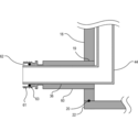
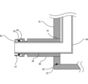
- the connecting portion 80 is constituted by an inner tube 81 and an outer tube 82.
- the nut 85 may be included in the configuration of the connecting portion 80.
- the inner tube 81 and the outer tube 82 are formed in a hollow cylindrical (columnar) shape.
- the outer diameter of the inner tube 81 is smaller than the inner diameter of the outer tube 82 and the outer diameter of the nozzle 44.
- An outer tube 82 is provided outside the inner tube 81.
- the outer tube 82 has a shape in which one end (upstream side, end portion on the preheating device 70 side) is closed and the other end (downstream side, end portion on the port 60 side) is opened.
- the connection wall 83 is welded to the outer surface of the inner tube 81.
- the inner tube 81 is configured to penetrate the outer tube 82, and the outer tube 82 and the inner tube 81 are integrally formed. Further, the entire length of the inner tube 81 is longer than the entire length of the outer tube 80.
- the connecting portion 80 has a double tube structure of an outer tube 82 and an inner tube 81.
- the inner diameter of the intermediate portion at both ends of the outer tube 82 is formed to be the same as the inner diameter of the nozzle 44.
- the other end of the outer tube 82 is provided with a stepped portion 84 that interferes with a nut 85 described later.
- the outer circumference and inner circumference diameter of the other end of the outer tube 82 are formed larger than the outer circumference and inner circumference diameter of one end.
- the inner diameter of the other end of the outer tube 82 is formed to be larger than the outer diameter of the nozzle 44.
- An open end 89 that is an end portion on the downstream side (port 60 side) of the inner tube 81 is formed to extend further downstream than the other end of the outer tube 82.
- the inner tube 81 is formed so as to extend into the port 60, that is, into the nozzle 44.
- the nut 85 as a fixing member has an opening 87 having a diameter slightly larger than the outer diameter of the outer tube 82, and is attached to be rotatable around the outer tube 82.
- connection between the port 60 and the connection unit 80 will be described with reference to FIG.
- a part of the stepped portion 64 of the connection portion 80 is fitted into the gap 62 provided inside the thread 61 of the port 60 together with the 0 ring 63 as a sealing member.
- the thread 61 on the port side and the thread 86 on the nut 85 side are fitted.
- the step portion 84 is pushed by the step receiving portion 88 of the nut 85, the O-ring 63 is crushed and the port 60 and the connection portion 80 can be connected in an airtight manner.
- the open end 89 of the inner pipe 81 is located downstream of the O-ring 63, that is, in the nozzle 44 (in the port 60).
- the heated gas directly comes into contact with the periphery of the O-ring installation portion at a high temperature.
- the O-ring installation portion is heated to a temperature higher than the heat-resistant temperature of the O-ring, and the O-ring may be deteriorated. Therefore, it has been difficult to heat the gas to a temperature higher than the heat resistance temperature of the O-ring, for example, higher than 100 to 350 ° C. which is a heat resistance temperature of a general O-ring.
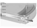
- the present embodiment as shown in FIG. 7, even when a high-temperature gas flows in the inner pipe 81, the temperature around the O-ring is maintained at about half or less of the temperature in the inner pipe 81. I understand that.
- the O-ring it is possible to prevent the O-ring from being heated to a temperature higher than the heat-resistant temperature by setting the O-ring to have a double-pipe structure and suppressing direct contact with high-temperature gas.
- the inner tube 81 may be extended to the opening 19. By extending the inner pipe 81 to the opening 19, it is possible to prevent the high temperature gas from being cooled before being supplied into the reaction pipe 10.
- connection part 80 is formed of a metal material that is heat resistant to high-temperature gas and hardly causes metal contamination.
- the connection part 80 is formed of a metal to which aluminum is added.
- an alumina film is formed on the inner wall surface of the connecting portion 80, that is, the gas flow path through which the gas flows.
- the alumina film can be formed, for example, by firing a metal material as described above.
- the alumina coating is preferably formed on the wall surface of a gas flow path formed of a metal material through which at least a high-temperature gas flows.
- the preheating device 70 may be formed of the same material as that of the connection portion 80. Further, for example, the preheating device 70 and the connecting portion 80 may be integrally formed. With such a configuration, it is possible to prevent the heated gas from being cooled (heat radiation) due to the difference in material between the preheating device 70 and the connection portion 80, and to further reduce metal contamination.
- the processing gas heated to a high temperature by the preheating device 70 can be supplied into the processing apparatus 2, the desired gas decomposition control can be performed, and the uniformity of the film is improved. Can be made. Since the heated gas flows through the inner pipe portion, the high-temperature gas does not directly contact the periphery of the O-ring of the outer pipe. Further, the processing gas that circulates around the O-ring after exiting the inner pipe 81 is equal to or lower than the heat resistance temperature of the O-ring. Thereby, even if the gas is heated to a temperature higher than the heat resistant temperature of the O-ring, the deterioration of the O-ring can be suppressed, and the breakage and deterioration of the O-ring can be prevented.
- the periphery of the O-ring 63 can be cooled by providing an annular cooling flow path 64 in the vicinity of the thread 63 and the gap 62 of the port 60 and flowing cooling water therein. Further, the risk of damage to the O-ring 63 can be further reduced. With such a configuration, the processing gas can be heated to a higher temperature.
- the annular cooling flow path 64 is not limited to the configuration embedded in the port 60, and may be configured such that a water cooling tube is wound around the outer periphery of the connection portion 80.
- the processing chamber 14 is evacuated (reduced pressure) by the vacuum pump 52 so that the inside of the processing chamber 14 has a predetermined pressure (degree of vacuum).
- the pressure in the processing chamber 14 is measured by the pressure sensor 48, and the APC valve 50 is feedback-controlled based on the measured pressure information.
- the wafer W in the processing chamber 14 is heated by the heater 12 so as to reach a predetermined temperature.
- the power supply to the heater 12 is feedback-controlled based on the temperature information detected by the temperature detector 16 so that the processing chamber 14 has a predetermined temperature distribution. Further, the rotation of the boat 26 and the wafer W by the rotation mechanism 30 is started.
- the preheating device 70 is turned on.
- the preheating device 70 is turned off or lower than the film forming temperature before and after the film forming process.
- the O 2 gas is heated to a high temperature, for example, 800 ° C. by the preheating device 70.
- the O 2 gas is controlled to have a desired flow rate by the MFC 38b, and is supplied into the processing chamber 14 through the gas supply pipe 36b, the preheating device 70, the connection portion 80, and the nozzle 44b. With such a configuration, the O 2 gas can be heated to a high temperature in advance before being introduced into the processing chamber 14.
- Examples of processing conditions for forming the SiO film on the wafer W include the following. Processing temperature (wafer temperature): 300 ° C. to 1000 ° C. Processing pressure (pressure in processing chamber) 1 Pa to 4000 Pa, DCS gas: 100 sccm to 10,000 sccm, O 2 gas: 100 sccm to 10,000 sccm, N 2 gas: 100 sccm to 10,000 sccm, By setting each processing condition to a value within the respective range, it is possible to appropriately progress the film forming process.
- the processing gas can be heated to a high temperature higher than the heat resistant temperature of the O-ring, it is possible to promote decomposition of the processing gas and improve reactivity. Thereby, the quality of film formation can be improved, and the yield of devices can be improved.
- the O-ring installation part a double tube structure of an inner tube and an outer tube, it is possible to suppress the heat of the processing gas flowing in the inner tube from being propagated around the O-ring. Thereby, since an O-ring can be maintained below heat-resistant temperature, deterioration of an O-ring can be suppressed and an apparatus operation rate can be improved.
- a connecting part may be included in the gas supply pipe.
- the end of the gas supply pipe (the side connected to the gas introduction port) may have the same configuration as the connection.
- the connecting portion may be welded and fixed to the end portion of the gas supply pipe.
- the processing gas is heated by passing the processing gas into the preheating device.
- an external heater such as a tape heater is installed in the gas supply pipe so that the processing gas passing through the gas supply pipe is heated. Also good.
- the present invention can be applied to the case where the source gas is heated.
- connection portion 80 may have a flange shape and may be fixed with screws. Even in these cases, similarly to the above-described embodiment, the temperature of the connection portion can be maintained at a temperature equal to or lower than the heat resistance temperature of each sealing member.
- the present invention is not limited to such an aspect.
- the present invention can be suitably applied to a case where a processing gas is heated and used in a process such as an oxidation process, a diffusion process, an annealing process, and an etching process on a wafer W or a film formed on the wafer W. It is.
- a processing gas is heated and used in a process such as an oxidation process, a diffusion process, an annealing process, and an etching process on a wafer W or a film formed on the wafer W.
- a processing gas is heated and used in a process such as an oxidation process, a diffusion process, an annealing process, and an etching process on a wafer W or a film formed on the wafer W.
- a vertical apparatus it can apply suitably also to a single wafer apparatus.
Landscapes
- Chemical & Material Sciences (AREA)
- General Chemical & Material Sciences (AREA)
- Chemical Kinetics & Catalysis (AREA)
- Engineering & Computer Science (AREA)
- Materials Engineering (AREA)
- Mechanical Engineering (AREA)
- Metallurgy (AREA)
- Organic Chemistry (AREA)
- Chemical Vapour Deposition (AREA)
Abstract
Description
基板を処理する反応管内にガスを導入するよう構成されたガス導入部と、
前記ガスを前記反応管外で加熱する加熱部と、
前記ガス導入部と前記加熱部との間に設置される接続部と、を有し、
前記接続部は、
前記ガス導入部と密閉部材を介して接続される外管と、
前記外管よりも小さい径に形成され、一端が前記加熱部と接続し、他端が少なくとも前記密閉部材が設置される位置まで延伸する内管と、で構成される技術が提供される。
以下、図面を参照しながら、本発明の限定的でない例示の実施形態について説明する。全図面中、同一または対応する構成については、同一または対応する参照符号を付し、重複する説明を省略する。
図3に示すように、マニホールド18の側壁には、ノズル44の基部を挿入するための開口部(貫通穴)19が、ノズルと同数設けられている。マニホールド18の開口部19には、挿入されたノズル44の基部を保持するガス導入部(ポート)60が、マニホールド18の外側に突出するように中空の円筒形状に構成されている。ノズル44は、マニホールド18に設けられた開口部19にノズル44の基部が挿入されるとともに、ポート60によって保持される。なお、ノズル44とポート60とは密着されており、反応容器内は気密に保たれるように構成されている。
次に、図4、5を用いて接続部80について説明する。ポート60の上流側には、継手部としての接続部80が設置される。ポート60と予備加熱装置70とは、接続部80を介して接続される。予備加熱装置70は、処理ガスを反応管10外で予め所定の温度、例えば、Oリング63の耐熱温度より高い温度に加熱する加熱部として構成される。予備加熱装置70がガス供給管36に設置される場合は、接続部80はポート60とガス供給管36とを接続するように構成されても良い。接続部80は、内管81および外管82により構成される。ナット85を接続部80の構成に含めて考えても良い。内管81および外管82は、中空の円筒(円柱)形状に形成される。内管81の外径は、外管82の内径およびノズル44の外径よりも小さく構成されている。
ポート60に接続部80を接続する際、ポート60のねじ山61の内側に設けられた間隙62に、密閉部材としての0リング63と共に接続部80の段差部64の一部分を嵌め込む。続いて、ナット85をポート60側に押しながら回転させることによって、ポート側のねじ山61とナット85側のねじ山86が嵌合する。そして、ナット85の段差受部88によって段差部84が押されることにより、Oリング63が圧潰され、ポート60と接続部80とを気密に接続することが出来る。ポート60と接続部80とが接続された状態において、内管81の開放端89はOリング63よりも下流側、すなわち、ノズル44内(ポート60内)に位置することとなる。
複数枚のウエハWがボート26に装填(ウエハチャージ)されると、ボート26は、ボートエレベータ32によって処理室14内に搬入(ボートロード)され、反応管10の下部開口は蓋部22によって気密に閉塞(シール)された状態となる。
処理室14内が所定の圧力(真空度)となるように、真空ポンプ52によって真空排気(減圧排気)される。処理室14内の圧力は、圧力センサ48で測定され、この測定された圧力情報に基づきAPCバルブ50が、フィードバック制御される。また、処理室14内のウエハWが所定の温度となるように、ヒータ12によって加熱される。この際、処理室14が所定の温度分布となるように、温度検出部16が検出した温度情報に基づきヒータ12への通電具合がフィードバック制御される。また、回転機構30によるボート26およびウエハWの回転を開始する。
[原料ガス供給工程]
処理室14内の温度が予め設定された処理温度に安定すると、処理室14内のウエハWに対してDCSガスを供給する。DCSガスは、MFC38aにて所望の流量となるように制御され、ガス供給管36aおよびノズル44aを介して処理室14内に供給される。
次に、DCSガスの供給を停止し、真空ポンプ52により処理室14内を真空排気する。この時、不活性ガス供給部から不活性ガスとしてN2ガスを処理室14内に供給しても良い(不活性ガスパージ)。
次に、処理室14内のウエハWに対してO2ガスを供給する。処理室14内にO2ガスを供給する前に、予備加熱装置70をONとしておく。予備加熱装置70は、成膜処理の前後においては、OFFとするか、成膜温度よりも低い温度とする。O2ガスは、予備加熱装置70で高温に、例えば、800℃に加熱される。O2ガスは、MFC38bにて所望の流量となるように制御され、ガス供給管36b、予備加熱装置70、接続部80およびノズル44bを介して処理室14内に供給される。このような構成により、処理室14内に導入される前に、O2ガスを予め高い温度に加熱することができる。
次に、O2ガスの供給を停止し、真空ポンプ52により処理室14内を真空排気する。この時、不活性ガス供給部からN2ガスを処理室14内に供給しても良い(不活性ガスパージ)。
所定膜厚の膜を形成した後、不活性ガス供給部からN2ガスが供給され、処理室14内がN2ガスに置換されると共に、処理室14の圧力が常圧に復帰される。その後、ボートエレベータ32により蓋部22が降下されて、ボート26が反応管10から搬出(ボートアンロード)される。その後、処理済ウエハWはボート26より取出される(ウエハディスチャージ)。
処理温度(ウエハ温度):300℃~1000℃、
処理圧力(処理室内圧力)1Pa~4000Pa、
DCSガス:100sccm~10000sccm、
O2ガス:100sccm~10000sccm、
N2ガス:100sccm~10000sccm、
それぞれの処理条件を、それぞれの範囲内の値に設定することで、成膜処理を適正に進行させることが可能となる。
本実施形態によれば、以下に示す1つ又は複数の効果が得られる。
(1)処理ガスをOリングの耐熱温度より高い温度の高温に加熱することができるため、処理ガスの分解を促進させたり、反応性を向上させたりすることが可能となる。これにより、成膜の品質を向上させることができ、デバイスの歩留まりを向上させることが可能となる。
(2)Oリング設置部分を、内管と外管との二重管構造とすることにより、内管内を流れる処理ガスの熱がOリング周辺に伝播することを抑制することができる。これにより、Oリングを耐熱温度以下に維持することができるため、Oリングの劣化を抑制することができ、装置稼働率を向上させることができる。
(3)内管をガスノズル内まで延出させることにより、接続部内での処理ガスの冷却(放熱)を抑制することができるため、高温を保ったまま処理ガスを処理室内に供給させることができ、膜の面間均一性および面内均一性を向上させることができる。
10 反応管
36 ガス供給管
60 ポート
63 Oリング
64 冷却路
70 予備加熱装置
80 接続部
81 内管
82 外管
85 ナット
89 解放端
Claims (12)
- 基板を処理する反応管内にガスを導入するよう構成されたガス導入部と、
前記ガスを前記反応管外で加熱する加熱部と、
前記ガス導入部と前記加熱部との間に設置される接続部と、を有し、
前記接続部は、
前記ガス導入部と密閉部材を介して接続される外管と、
前記外管よりも小さい径に形成され、一端が前記加熱部と接続し、他端が少なくとも前記密閉部材が設置される位置まで延伸する内管と、で構成される基板処理装置。 - 前記内管の全長は、前記外管の全長よりも長く形成される請求項1に記載の基板処理装置。
- 前記内管の他端は前記ガス導入部内まで延伸するよう構成される請求項2に記載の基板処理装置。
- 前記内管と前記外管とは一体に形成される請求項3に記載の基板処理装置。
- 前記加熱部は、前記密閉部材の耐熱温度よりも高い温度に前記ガスを加熱する請求項1に記載の基板処理装置。
- 前記接続部は前記加熱部と一体に形成される請求項5に記載の基板処理装置。
- 前記接続部と前記加熱部とは同じ金属材料で形成される請求項6に記載の基板処理装置。
- 前記ガスは、前記加熱部内および前記内管内に形成された流路を流れ、前記流路の壁面は、アルミナ皮膜が形成される請求項1に記載の基板処理装置。
- 前記金属材料はAlを含む金属材料であり、前記金属材料を焼成することにより、前記加熱部内および前記内管内に形成されるガス流路の壁面にアルミナ皮膜を形成する請求項7に記載の基板処理装置。
- 前記密閉部材を冷却する環状の冷却部材を備える請求項5に記載の基板処理装置。
- 基板を処理する反応管内にガスを導入するよう構成されたガス導入部と前記ガスを前記反応管外で加熱する加熱部との間に設置される継手部であって、
前記ガス導入部と密閉部材を介して接続される外管と、
前記外管よりも小さい径に形成され、一端が前記加熱部と接続し、他端が少なくとも前記密閉部材が設置される位置まで延伸する内管と、で構成される前記継手部。 - 反応管内に基板を搬入する工程と、
前記反応管外に設置された加熱部によって加熱されたガスを、ガス導入部を介して前記反応管内に供給し、前記基板を処理する工程と、を有し、
前記加熱部と前記ガス導入部とは、前記ガス導入部と密閉部材を介して接続される外管と、前記外管よりも小さい径に形成され、一端が前記加熱部と接続し、他端が少なくとも前記密閉部材が設置される位置まで延伸する内管とで構成される接続部を介して接続され、前記ガスは、前記密閉部材の耐熱温度よりも高い温度に加熱される半導体装置の製造方法。
Priority Applications (2)
| Application Number | Priority Date | Filing Date | Title |
|---|---|---|---|
| KR1020187009658A KR102133547B1 (ko) | 2016-02-08 | 2016-09-14 | 기판 처리 장치, 이음부 및 반도체 장치의 제조 방법 |
| JP2017566504A JP6561148B2 (ja) | 2016-02-08 | 2016-09-14 | 基板処理装置、継手部および半導体装置の製造方法 |
Applications Claiming Priority (2)
| Application Number | Priority Date | Filing Date | Title |
|---|---|---|---|
| JP2016-021845 | 2016-02-08 | ||
| JP2016021845 | 2016-02-08 |
Publications (1)
| Publication Number | Publication Date |
|---|---|
| WO2017138183A1 true WO2017138183A1 (ja) | 2017-08-17 |
Family
ID=59563778
Family Applications (1)
| Application Number | Title | Priority Date | Filing Date |
|---|---|---|---|
| PCT/JP2016/077143 Ceased WO2017138183A1 (ja) | 2016-02-08 | 2016-09-14 | 基板処理装置、継手部および半導体装置の製造方法 |
Country Status (3)
| Country | Link |
|---|---|
| JP (1) | JP6561148B2 (ja) |
| KR (1) | KR102133547B1 (ja) |
| WO (1) | WO2017138183A1 (ja) |
Cited By (1)
| Publication number | Priority date | Publication date | Assignee | Title |
|---|---|---|---|---|
| JP2020194972A (ja) * | 2020-08-12 | 2020-12-03 | 株式会社Kokusai Electric | 基板処理装置、半導体装置の製造方法、プログラム |
Citations (7)
| Publication number | Priority date | Publication date | Assignee | Title |
|---|---|---|---|---|
| WO1990012126A1 (fr) * | 1989-03-31 | 1990-10-18 | Canon Kabushiki Kaisha | Procede pour former un film polycristallin par depot en phase gazeuse par voie chimique |
| JPH0325230U (ja) * | 1989-07-20 | 1991-03-15 | ||
| JPH0471898U (ja) * | 1990-10-29 | 1992-06-25 | ||
| JPH04187592A (ja) * | 1990-11-22 | 1992-07-06 | Anelva Corp | Cvd装置 |
| JPH10231970A (ja) * | 1997-02-21 | 1998-09-02 | Mitsubishi Heavy Ind Ltd | 真空断熱配管継手 |
| JP2010045251A (ja) * | 2008-08-14 | 2010-02-25 | Shin Etsu Handotai Co Ltd | 縦型熱処理装置及び熱処理方法 |
| JP2010090422A (ja) * | 2008-10-07 | 2010-04-22 | Soken Kogyo Kk | 流体加熱装置およびこれを利用した半導体処理装置 |
Family Cites Families (1)
| Publication number | Priority date | Publication date | Assignee | Title |
|---|---|---|---|---|
| KR20090001187U (ko) * | 2007-07-30 | 2009-02-04 | 최양일 | 배관 보호관 어셈블리 및 이를 포함하는 배관 보호상자 |
-
2016
- 2016-09-14 WO PCT/JP2016/077143 patent/WO2017138183A1/ja not_active Ceased
- 2016-09-14 KR KR1020187009658A patent/KR102133547B1/ko active Active
- 2016-09-14 JP JP2017566504A patent/JP6561148B2/ja active Active
Patent Citations (7)
| Publication number | Priority date | Publication date | Assignee | Title |
|---|---|---|---|---|
| WO1990012126A1 (fr) * | 1989-03-31 | 1990-10-18 | Canon Kabushiki Kaisha | Procede pour former un film polycristallin par depot en phase gazeuse par voie chimique |
| JPH0325230U (ja) * | 1989-07-20 | 1991-03-15 | ||
| JPH0471898U (ja) * | 1990-10-29 | 1992-06-25 | ||
| JPH04187592A (ja) * | 1990-11-22 | 1992-07-06 | Anelva Corp | Cvd装置 |
| JPH10231970A (ja) * | 1997-02-21 | 1998-09-02 | Mitsubishi Heavy Ind Ltd | 真空断熱配管継手 |
| JP2010045251A (ja) * | 2008-08-14 | 2010-02-25 | Shin Etsu Handotai Co Ltd | 縦型熱処理装置及び熱処理方法 |
| JP2010090422A (ja) * | 2008-10-07 | 2010-04-22 | Soken Kogyo Kk | 流体加熱装置およびこれを利用した半導体処理装置 |
Cited By (2)
| Publication number | Priority date | Publication date | Assignee | Title |
|---|---|---|---|---|
| JP2020194972A (ja) * | 2020-08-12 | 2020-12-03 | 株式会社Kokusai Electric | 基板処理装置、半導体装置の製造方法、プログラム |
| JP7038770B2 (ja) | 2020-08-12 | 2022-03-18 | 株式会社Kokusai Electric | 基板処理装置、半導体装置の製造方法、プログラム |
Also Published As
| Publication number | Publication date |
|---|---|
| KR102133547B1 (ko) | 2020-07-13 |
| KR20180050709A (ko) | 2018-05-15 |
| JPWO2017138183A1 (ja) | 2018-12-20 |
| JP6561148B2 (ja) | 2019-08-14 |
Similar Documents
| Publication | Publication Date | Title |
|---|---|---|
| US11222796B2 (en) | Substrate processing apparatus | |
| KR102074668B1 (ko) | 기판 처리 장치, 석영 반응관, 클리닝 방법 및 프로그램 | |
| JP6605398B2 (ja) | 基板処理装置、半導体の製造方法およびプログラム | |
| US10351951B2 (en) | Substrate treatment apparatus including reaction tube with opened lower end, furnace opening member, and flange configured to cover upper surface of the furnace opening member | |
| WO2014192871A1 (ja) | 基板処理装置、半導体製造装置の製造方法及び炉口蓋体 | |
| KR102076643B1 (ko) | 기판 처리 장치 및 반도체 장치의 제조 방법 | |
| JP2020017757A (ja) | 基板処理装置、反応容器および半導体装置の製造方法 | |
| US20180087709A1 (en) | Substrate processing apparatus and heat insulating pipe structure | |
| US11219096B2 (en) | Substrate processing apparatus and furnace opening assembly thereof | |
| US9793112B2 (en) | Method of manufacturing semiconductor device and non-transitory computer-readable recording medium | |
| KR102935300B1 (ko) | 노구부 구조, 기판 처리 장치 및 반도체 장치의 제조 방법 | |
| KR20170090967A (ko) | 기판 처리 장치, 반도체 장치의 제조 방법 및 기록 매체 | |
| TW202316560A (zh) | 支撐件、基板處理裝置、及半導體裝置的製造方法 | |
| JP6561148B2 (ja) | 基板処理装置、継手部および半導体装置の製造方法 | |
| WO2018150537A1 (ja) | 基板処理装置、半導体装置の製造方法およびプログラム | |
| JP4782761B2 (ja) | 成膜装置 | |
| WO2016046947A1 (ja) | 基板保持具、基板処理装置および半導体装置の製造方法 | |
| WO2025158707A1 (ja) | 温度制御システム、温度制御方法、半導体装置の製造方法及び基板処理装置 |
Legal Events
| Date | Code | Title | Description |
|---|---|---|---|
| 121 | Ep: the epo has been informed by wipo that ep was designated in this application |
Ref document number: 16889884 Country of ref document: EP Kind code of ref document: A1 |
|
| ENP | Entry into the national phase |
Ref document number: 20187009658 Country of ref document: KR Kind code of ref document: A |
|
| WWE | Wipo information: entry into national phase |
Ref document number: 2017566504 Country of ref document: JP |
|
| NENP | Non-entry into the national phase |
Ref country code: DE |
|
| 122 | Ep: pct application non-entry in european phase |
Ref document number: 16889884 Country of ref document: EP Kind code of ref document: A1 |