WO2017138097A1 - X線撮影装置 - Google Patents
X線撮影装置 Download PDFInfo
- Publication number
- WO2017138097A1 WO2017138097A1 PCT/JP2016/053852 JP2016053852W WO2017138097A1 WO 2017138097 A1 WO2017138097 A1 WO 2017138097A1 JP 2016053852 W JP2016053852 W JP 2016053852W WO 2017138097 A1 WO2017138097 A1 WO 2017138097A1
- Authority
- WO
- WIPO (PCT)
- Prior art keywords
- harmonic component
- ray
- image
- removal process
- processing unit
- Prior art date
- Legal status (The legal status is an assumption and is not a legal conclusion. Google has not performed a legal analysis and makes no representation as to the accuracy of the status listed.)
- Ceased
Links
Images




Classifications
-
- A—HUMAN NECESSITIES
- A61—MEDICAL OR VETERINARY SCIENCE; HYGIENE
- A61B—DIAGNOSIS; SURGERY; IDENTIFICATION
- A61B6/00—Apparatus or devices for radiation diagnosis; Apparatus or devices for radiation diagnosis combined with radiation therapy equipment
Definitions
- the present invention relates to an X-ray imaging apparatus, and more particularly to an X-ray imaging apparatus that captures an X-ray image using a grid that removes X-rays scattered by a subject.
- an X-ray imaging apparatus that captures an X-ray image using a grid is known.
- Such an X-ray imaging apparatus is disclosed in, for example, Japanese Patent Application Laid-Open No. 2002-152467.
- the X-ray imaging apparatus disclosed in the above Japanese Patent Laid-Open No. 2002-152467 includes an X-ray irradiation unit that irradiates a subject with X-rays, an X-ray detection unit that detects X-rays transmitted through the subject, And a grid that is disposed on the detection surface side of the line detection unit and removes scattered X-rays.
- the grid is a lattice-shaped member in which linear shielding portions made of lead that absorb X-rays are arranged with a minute interval (slit) therebetween.
- the X-ray imaging apparatus disclosed in Japanese Patent Laid-Open No. 2002-152467 performs a removal process for extracting a harmonic component of a moire pattern by Fourier transforming an X-ray image and removing it from the first harmonic component to the fourth harmonic component.
- An image processing unit that outputs an X-ray processed image from which the moire pattern has been removed is provided.
- the present invention has been made to solve the above-described problems, and one object of the present invention is to unnecessarily degrade the resolution of an X-ray image by removing harmonic components of a moire pattern.
- An X-ray imaging apparatus capable of being suppressed is provided.
- an X-ray imaging apparatus includes an X-ray irradiation unit that irradiates a subject with X-rays, and an X-ray detection unit that detects X-rays transmitted through the subject.
- the moiré pattern removal process caused by the grid arranged on the detection surface side of the X-ray detection unit and removing scattered X-rays and the grid reflected in the X-ray image obtained by the X-ray detection unit,
- An image processing unit that outputs an X-ray processed image after the removal process, and the image processing unit extracts a harmonic component that constitutes a moire pattern from the X-ray image, and outputs a first harmonic component as a first harmonic component.
- the content of the removal process is changed according to the intensity of the second-order or third-order higher harmonic component higher than the first harmonic component.
- the harmonic component constituting the moire pattern is extracted from the X-ray image, and the first harmonic component as the first harmonic component is extracted.
- an image processing unit is provided that changes the content of the removal process in accordance with the intensity of the higher-order second-order or third-order higher-order harmonic component.
- the image processing unit generates a higher-order harmonic component and a lower-order harmonic component than the higher-order harmonic component according to the intensity of the higher-order harmonic component.
- the first removal processing to be removed and the second removal processing to remove higher-order harmonic components than the higher-order harmonic components without removing the higher-order harmonic components are switched.
- the high-order harmonic component can be removed by the first removal process, and when the intensity of the high-order harmonic component is not high, 2 High-order harmonic components can be left by the removal process.
- the lower harmonic component than the higher harmonic component can be removed, so that the reflection of the moire pattern can be effectively removed.
- the higher harmonic component is a third harmonic component
- the first removal process is a removal process for removing the first harmonic component, the second harmonic component, and the third harmonic component.
- the second removal process is a removal process that removes the first harmonic component and the second harmonic component without removing the third harmonic component.
- the higher the harmonic component the smaller the influence of reflection. Therefore, whether or not the third harmonic component is removed on a case-by-case basis according to the intensity while reliably removing the first harmonic component and the second harmonic component that are relatively largely affected by reflection. Therefore, it is possible to effectively remove the reflection of the moire pattern while effectively suppressing a decrease in resolution due to the moire pattern removal process.
- the image processing unit has a higher-order harmonic component equal to or higher than a threshold value compared to a nearby frequency component.
- the first removal process is performed when the relative intensity peak is present, and the second removal process is performed when the high-order harmonic component has a relative intensity peak less than the threshold. If comprised in this way, the necessity for the removal according to the intensity
- the image processing unit is configured to be able to change the set value of the threshold.
- the threshold value for determining whether or not to remove higher-order harmonic components differs depending on the apparatus configuration of the X-ray imaging apparatus (characteristics of the X-ray irradiation unit and X-ray detection unit, grid pitch, etc.). For this reason, by making it possible to change the threshold setting value, for example, even when the apparatus configuration is changed, or between X-ray imaging apparatuses having different specifications, the image processing unit can be shared only by changing the threshold setting value. And the threshold value can be easily optimized.
- the image processing unit preferably extracts a high-order harmonic component from a removed image from which a lower-order harmonic component is removed from a higher-order harmonic component. And the content of the removal process on the removed image is changed according to the intensity of the high-order harmonic component. If comprised in this way, since a high-order harmonic component is extracted after removing a low-order harmonic component, a part of low-order (1st order and 2nd order, or 1st order) harmonic component is removed. It is possible to suppress misrecognition as a high-order harmonic component or missing a high-order harmonic component due to a low-order harmonic component. As a result, high-order harmonic components can be extracted more reliably and appropriate removal processing can be executed.
- the image processing unit is preferably configured to extract a high-order harmonic component in a frequency range including an estimated value of a peak frequency of the high-order harmonic component
- the processing unit is configured to change the set value of the frequency range.
- the peak frequency of the higher-order harmonic component does not always match the estimated value. Therefore, high-order harmonic components can be extracted more reliably by extracting high-order harmonic components in the frequency range including the estimated value of the peak frequency.
- the frequency range for performing extraction varies depending on the device configuration of the X-ray imaging apparatus (characteristics of the X-ray irradiation unit and X-ray detection unit, grid pitch, and the like). Therefore, by enabling the setting value of the frequency range to be changed, for example, when the apparatus configuration is changed or between X-ray imaging apparatuses having different specifications, the image processing unit can be changed by simply changing the setting value of the frequency range. Can be shared.
- FIG. 1 is a schematic diagram illustrating an overall configuration of an X-ray imaging apparatus according to an embodiment of the present invention. It is a schematic diagram for demonstrating an X-ray image. It is a frequency spectrum which showed an example of the Fourier-transform result with respect to an X-ray image. It is a frequency spectrum which showed an example of the Fourier-transform result with respect to a removal image. It is a schematic diagram for demonstrating the 1st removal process and 2nd removal process by an image process part. It is the figure which showed the example 1 of the spectrum intensity for every frequency division in a frequency range. It is the figure which showed the example 2 of the spectrum intensity for every frequency division in a frequency range.
- the X-ray imaging apparatus 100 irradiates a subject P with X-rays and detects X-rays transmitted through the subject P, thereby transmitting a transmission image inside the subject P.
- the X-ray imaging apparatus 100 is an X-ray diagnostic apparatus (medical X-ray apparatus) used for clinical diagnosis in the medical field.
- the subject P is mainly a human (patient).
- the X-ray imaging apparatus 100 includes an X-ray irradiation unit 1 that irradiates a subject P with X-rays, an X-ray detection unit 2 that detects X-rays transmitted through the subject P, and a detection surface side of the X-ray detection unit 2 And a grid 3 for removing scattered X-rays.
- the X-ray irradiation unit 1 and the X-ray detection unit 2 are disposed so as to face each other with the top plate 4 on which the subject P is placed.
- the grid 3 is disposed at a position between the X-ray detection unit 2 and the top plate 4.
- the X-ray irradiation unit 1, the X-ray detection unit 2, and the grid 3 are supported by a moving mechanism 5 so as to be movable.
- the top plate 4 can be moved in the horizontal direction by the top plate drive unit 6.
- the X-ray irradiation unit 1, the X-ray detection unit 2, the grid 3, and the top plate 4 are moved via the moving mechanism 5 and the top plate driving unit 6 so that the region of interest of the subject P can be imaged.
- the X-ray imaging apparatus 100 includes a control unit 7 that controls the moving mechanism 5 and the top plate driving unit 6.
- the X-ray irradiation unit 1 includes an X-ray tube 1a that generates X-rays by supplying power, and is connected to a high voltage generation unit (not shown).
- the X-ray tube 1 a is arranged with the X-ray emission direction facing the detection surface of the X-ray detection unit 2.
- the X-ray irradiation unit 1 is connected to the control unit 7.
- the control unit 7 controls the X-ray irradiation unit 1 in accordance with preset imaging conditions such as tube voltage, tube current, and X-ray irradiation time, and generates X-rays from the X-ray tube 1a.
- the X-ray detection unit 2 detects X-rays irradiated from the X-ray irradiation unit 1 and transmitted through the subject P, and outputs a detection signal corresponding to the detected X-ray intensity.
- the X-ray detection unit 2 is configured by, for example, an FPD (Flat Panel Detector).
- the X-ray imaging apparatus 100 includes an image processing unit 8 that acquires an X-ray detection signal from the X-ray detection unit 2 and generates an X-ray image 21 (see FIG. 2).
- the X-ray detection unit 2 outputs an X-ray image (detection signal) having a predetermined resolution to the image processing unit 8.
- the grid 3 is a grid-like member in which linear shielding parts made of lead that absorb X-rays are arranged with a minute interval (slit) therebetween.
- the grid 3 is arranged so that, for example, the shielding portions extend along the vertical direction (Y direction in FIG. 2) of the X-ray image 21 and are arranged at a predetermined pitch in the horizontal direction.
- the control unit 7 includes a CPU (Central Processing Unit), a ROM (Read Only Memory), a RAM (Random Access Memory), and the like.
- the CPU executes a predetermined control program, whereby each unit of the X-ray imaging apparatus 100 is controlled. It functions as a control unit for controlling.
- the control unit 7 performs control of the X-ray irradiation unit 1 and drive control of the moving mechanism 5 and the top plate driving unit 6.
- the X-ray imaging apparatus 100 includes a display unit 9, an operation unit 10, and a storage unit 11.
- the display unit 9 is a monitor such as a liquid crystal display.
- the operation unit 10 includes, for example, a keyboard and a mouse, a touch panel, other controllers, and the like.
- the storage unit 11 is configured by a storage device such as a hard disk drive.
- the control unit 7 is configured to perform control to display the image generated by the image processing unit 8 on the display unit 9.
- the control unit 7 is configured to accept an input operation via the operation unit 10.
- the imaging conditions of the X-ray image 21 are set in advance in the control unit 7 before imaging by being read out from the operation unit 10 or from the storage unit 11.
- the control unit 7 is configured to store image data, shooting conditions, and various set values in the storage unit 11.
- the image processing unit 8 includes, for example, a CPU, a ROM, a RAM, and the like common to the control unit 7. That is, the image processing unit 8 is configured on software by causing the CPU to execute an image processing program.
- the image processing unit 8 may be configured by dedicated hardware (processor) separate from the control unit 7.
- the image processing unit 8 performs a removal process of the moire pattern MP caused by the grid 3 reflected in the X-ray image 21 obtained by the X-ray detection unit 2, and the X-rays after the removal process
- the processed image 22 (see FIG. 5) is configured to be output to the control unit 7.
- the X-ray processed image 22 processed by the image processing unit 8 is displayed on the display unit 9 and stored in the storage unit 11.
- the image processing unit 8 extracts harmonic components constituting the moire pattern MP from the X-ray image 21.
- the moire pattern MP is a periodic striped pattern that appears in the X-ray image 21 due to the difference between the resolution (pixel pitch) of the X-ray detection unit 2 and the pitch of the grid 3 (interval between the shielding units).
- the moire pattern MP is formed as a striped pattern extending along the direction of the shielding portion of the grid 3 (the Y direction in FIG. 2).
- the image processing unit 8 performs one-dimensional Fourier transform on the X-ray image 21 in which the moire pattern MP is reflected in the X direction orthogonal to the stripes of the moire pattern MP.
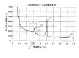
- the spectral intensity distribution of the X-ray image 21 as shown in FIG. 3 is obtained by Fourier transform.
- the image processing unit 8 changes the content of the removal process according to the intensity of the second-order or third-order higher harmonic component higher than the first harmonic component 31 as the first-order harmonic component. It is configured. In the present embodiment, an example in which the image processing unit 8 is configured to change the content of the removal process according to the intensity of the third harmonic component 33 will be described.
- the third harmonic component 33 is an example of the “high-order harmonic component” in the claims.
- the image processing unit 8 detects a harmonic component by detecting a peak of the spectrum. As shown in FIG. 3, the image processing unit 8 extracts a first harmonic component 31, a second harmonic component 32, and a third harmonic component 33, respectively.
- the resolution of the X-ray detection unit 2 has a pixel pitch of, for example, 139 ⁇ m and a Nyquist frequency of about 3.6 [lp / mm].
- the image processing unit 8 detects the peak of the first harmonic component 31 in the vicinity of the estimated value (2.2 [lp / mm]) from the spectrum distribution.
- FIG. 3 shows an example in which the first harmonic component 31 appears at about 2.0 [lp / mm].
- the image processing unit 8 similarly extracts the peak of the second harmonic component 32 in the vicinity of the estimated value.
- FIG. 3 shows an example in which the second harmonic component 32 appears at about 3.3 [lp / mm].
- the image processing unit 8 is configured to extract the third harmonic component 33 in the frequency range R including the estimated value E of the peak frequency of the third harmonic component 33.
- the first harmonic component 31 and the second harmonic component 32 are removed from the X-ray image 21 prior to the extraction of the third harmonic component 33.
- the image processing unit 8 applies the removed image 23 (see FIG. 5) from which the lower harmonic components (the first harmonic component 31 and the second harmonic component 32) than the third harmonic component 33 are removed.
- the third harmonic component 33 is extracted.
- the image processing unit 8 performs Fourier transform once again on the removed image 23 from which the first harmonic component 31 and the second harmonic component 32 have been removed, so that the spectral intensity distribution of the removed image 23 shown in FIG. get.
- the image processing unit 8 extracts the third harmonic component 33 from the spectral intensity distribution of the removed image 23.
- the peak frequency of the third harmonic component 33 is three times the frequency of the first harmonic component 31.
- the image processing unit 8 extracts the third harmonic component 33 in the frequency range R set with a predetermined width on both sides of the estimated value E in the spectrum.
- the frequency range R is, for example, a range of 0.2 [lp / mm] on both sides of the estimated value E in the spectrum (1.0 [lp / mm centered on 1.2 [lp / mm]). ] And a frequency range of 1.4 [lp / mm] or less.
- the image processing unit 8 is configured to be able to change the set value of the frequency range R.
- the image processing unit 8 changes the set value of the frequency range R by, for example, an operation input via the operation unit 10 or reading a set value from the storage unit 11.
- a peak in the set frequency range R is detected as the third harmonic component 33.
- 3 and 4 show an example in which the third harmonic component 33 appears at about 1.29 [lp / mm].
- the image processing unit 8 is configured to switch between the first removal process and the second removal process in accordance with the intensity of the higher-order harmonic component (third harmonic component 33).
- the first removal process is a removal process for removing higher-order harmonic components (third harmonic component 33) and higher-order harmonic components than the higher-order harmonic components. That is, in the present embodiment, the first removal process is a removal process for removing the first harmonic component 31, the second harmonic component 32, and the third harmonic component 33.
- the second removal process is a removal process that removes higher-order harmonic components (third-harmonic component 33) without removing higher-order harmonic components than the higher-order harmonic components.
- the second removal process is a removal process that removes the first harmonic component 31 and the second harmonic component 32 without removing the third harmonic component 33.
- the image processing unit 8 removes the first harmonic component 31 and the second harmonic component 32 when performing either the first removal process or the second removal process.
- the image processing unit 8 determines the first harmonic component 31 and the second harmonic from the Fourier transform result (spectral intensity distribution) shown in FIG. Filters corresponding to the spectrum of the component 32 are respectively created.
- the image processing unit 8 extracts the first harmonic component 31 and the second harmonic component 32 using the created filter, respectively, and extracts the extracted first harmonic component 31 and second harmonic component 32 to the moire pattern MP. Is subtracted from the X-ray image 21 in which is reflected.
- the 1st harmonic component 31 and the 2nd harmonic component 32 are removed from the X-ray image 21, and the removal image 23 from which the 1st harmonic component 31 and the 2nd harmonic component 32 were removed is obtained.
- the extraction of the third harmonic component 33 is performed based on the Fourier transform result for the removed image 23 as described above.
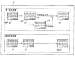
- the image processing unit 8 removes the third harmonic component 33 in the first removal process, and does not remove the third harmonic component 33 in the second removal process. Therefore, in the case of the second removal process, as shown in FIG. 5, the removed image 23 from which the first harmonic component 31 and the second harmonic component 32 have been removed is output as the X-ray processed image 22. The contents of the first removal process will be described later. Whether the first removal process or the second removal process is performed depends on the relative intensity of the peak of the third harmonic component 33 in the Fourier transform result (spectral intensity distribution).
- the image processing unit 8 performs the first removal process when the third harmonic component 33 has a relative intensity peak that is equal to or higher than a threshold value TH (see FIG. 4) as compared with a nearby frequency component.
- a threshold value TH see FIG. 4
- the second removal process is performed.
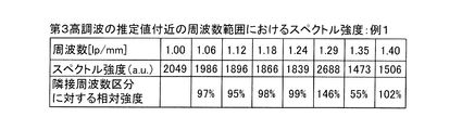
- the image processing unit 8 divides the frequency range R from which the third harmonic component 33 is extracted into a plurality of frequency segments, and acquires the spectrum intensity in each frequency segment. Then, the image processing unit 8 determines whether or not the relative intensity of the spectrum with respect to the adjacent frequency section is equal to or higher than the threshold value TH as a comparison with the nearby frequency component.
- the image processing unit 8 calculates, as a relative intensity, a ratio (percentage) between the spectral intensity in the focused frequency section and the spectral intensity in the adjacent (lower frequency side) frequency section among the frequency sections. Then, the image processing unit 8 performs the first removal process if there is a section whose relative intensity is greater than or equal to the threshold TH among the frequency sections, and performs the second removal process if there is no section greater than the threshold TH. I do.
- the relative intensity threshold TH is set to 120%, for example.
- the image processing unit 8 is configured to be able to change the set value of the threshold value TH.
- the image processing unit 8 changes the setting value of the threshold value TH by, for example, an operation input via the operation unit 10 or reading a setting value from the storage unit 11.
- Example 2 shown in FIG. 7, there is no division that is equal to or higher than the threshold TH (120%) in any frequency division. Therefore, in the case of Example 2, the image processing unit 8 selects the second removal process (see FIG. 5) that does not remove the third harmonic component 33. That is, the image processing unit 8 outputs the removed image 23 from which the first harmonic component 31 and the second harmonic component 32 are removed as the X-ray processed image 22.
- This example 2 indicates that the third harmonic component 33 does not have an intensity that reduces the visibility of the image when the X-ray processed image 22 is viewed. That is, in Example 2, since it can be determined that the moire pattern MP due to the third harmonic component 33 is hardly reflected in the image, it is unnecessary to remove the third harmonic component 33 due to the removal process. This corresponds to a case where it can be determined that degradation of resolution is suppressed.
- 3 and 4 show examples in which the intensity of the third harmonic component 33 is large (corresponding to Example 1 in FIG. 6).
- the image processing unit 8 performs the first removal process for removing the third harmonic component 33 and the removal of the third harmonic component 33 in accordance with the intensity of the third harmonic component 33. Is switched to the second removal process that is not performed. In other words, the image processing unit 8 determines whether or not the moiré pattern MP due to the third harmonic component 33 is reflected in the X-ray image 21 (removed image 23), and the third processing is performed according to the presence or absence of the reflection. It is configured to determine whether or not to remove the harmonic component 33.
- the removal of the first harmonic component 31 and the second harmonic component 32 is as described above.
- the image processing unit 8 performs a removal process different from that of the first harmonic component 31 and the second harmonic component 32.
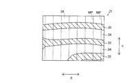
- the image processing unit 8 extracts a flat region 34 having a small luminance change from the removed image 23 and removes the third harmonic component 33 from the flat region 34.
- a process that does not remove the third harmonic component 33 is performed in the region 35 (hatched portion) other than the flat region 34. That is, in the first removal process, the first harmonic component 31, the second harmonic component 32, and the third harmonic component 33 are removed from a part (flat region 34) of the removed image 23, and the remaining portion of the removed image 23 is left.
- a part (region 35 other than the flat region 34) the first harmonic component 31 and the second harmonic component 32 are removed, and the third harmonic component 33 is not removed.
- FIG. 2 shows the X-ray image 21, the flat area 34 and the area 35 are the same in both the X-ray image 21 and the removed image 23.
- the third harmonic component 33 is partially (locally) removed is that the moire pattern MP is conspicuous in the flat region 34 where the luminance change is small, while the region 35 other than the flat region 34 (the luminance change is relatively large). This is because it is difficult to be recognized in (region). As a result, even when the third harmonic component 33 is removed, the resolution process (reduced visibility) of the X-ray processed image 22 is reduced by performing the removal process only on the conspicuous part (flat region 34) in the image. It is possible to suppress as much as possible.
- the region 35 where the luminance change is large is a region where a structure such as a bone is reflected
- the flat region 34 is equivalent to a region where a meat portion without a structure is reflected, for example.
- the image processing unit 8 outputs the third harmonic removed image 24 obtained by further removing the third harmonic component 33 from the removed image 23 for the flat region 34, and the removed image 23 for the region 35 other than the flat region 34. Is generated, and the generated composite image is output as the X-ray processed image 22.
- the image processing unit 8 creates a filter corresponding to the spectrum of the third harmonic component 33 from the Fourier transform result (spectral intensity distribution) of the removed image 23 shown in FIG.
- the image processing unit 8 removes the third harmonic component 33 from the removed image 23 by subtracting the third harmonic component 33 extracted using the created filter from the removed image 23. As a result, a third harmonic removal image 24 (see FIG. 5) is acquired.
- the image processing unit 8 extracts the flat area 34.
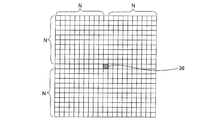
- the number of surrounding pixels N is, for example, about 10 pixels.
- the image processing unit 8 acquires the luminance change amount F ⁇ b> 2 for all the pixels of the removed image 23.
- the image processing unit 8 divides the removed image 23 into a plurality of partitioned areas 37 and smoothes the value of the luminance change amount F ⁇ b> 2 of the pixels included in the partitioned areas 37.
- the size of the partition area 37 is not particularly limited, but is 16 ⁇ 16 pixels, for example.
- the image processing unit 8 performs addition averaging of the luminance change amount F2 of each pixel in the partition area 37 of 16 ⁇ 16 pixels to obtain an addition average value F3. Then, the image processing unit 8 sets the luminance change amount of each pixel in the partition area 37 as the addition average value F3. That is, a common luminance change amount F3 is given to each pixel in the partition area 37 of 16 ⁇ 16 pixels.
- the luminance change amount F ⁇ b> 3 is acquired for each partition area 37.
- the image processing unit 8 removes the third harmonic component 33 and the region 35 other than the flat region 34 (removes the third harmonic component 33) according to the luminance change amount F3 calculated for each divided region 37. Discriminating area). That is, the image processing unit 8 sets the flat region 34 when the luminance change amount F3 is less than the change amount threshold, and sets the region 35 other than the flat region 34 when the luminance change amount F3 is equal to or greater than the change amount threshold. Since the pixels in each partition area 37 (16 ⁇ 16 pixels) have a common brightness change amount F3, the image processing unit 8 determines the threshold value of the brightness change amount F3 (whether it is a flat area 34 or not) with each partition area 37 as a unit. Judgment). Note that the threshold determination may be performed for the luminance change amount F ⁇ b> 2 for each pixel of the removed image 23 without dividing the removed image 23 into the plurality of partitioned regions 37.
- the image processing unit 8 outputs the third harmonic removal image 24 in which the third harmonic component 33 is removed from the removal image 23 for the flat region 34 in which the luminance change amount F3 is less than the change amount threshold value. To do. For regions where the luminance change amount F3 is equal to or greater than the change amount threshold (regions other than the flat region 34), the image processing unit 8 outputs the removed image 23 as it is. That is, as shown in FIG. 10, in the case of the first removal process, the image processing unit 8 creates a composite image of the third harmonic removal image 24 (flat region 34) and the removal image 23 (region 35), The created composite image is output as an X-ray processed image 22.
- the moire pattern MP caused by the third harmonic component 33 remains in the region 35, but the luminance change amount is large as described above, so that the image visibility is hardly affected.
- a dotted line portion indicating a slightly remaining moire pattern MP caused by the third harmonic component 33 is illustrated in the region 35.
- step S1 in FIG. 11 the X-ray image 21 is acquired.
- the control unit 7 shown in FIG. 1 irradiates the subject P with X-rays from the X-ray irradiation unit 1 in accordance with preset imaging conditions.
- X-rays that have passed through the subject P are detected by the X-ray detector 2, and the image processor 8 acquires an X-ray image 21 (see FIG. 2) from the X-ray detector 2.
- step S ⁇ b> 2 the image processing unit 8 performs a one-dimensional Fourier transform on the X-ray image 21, and obtains the first harmonic component 31 and the second harmonic component 32 from the obtained frequency spectrum (see FIG. 3). Extract.
- step S3 the image processing unit 8 removes the extracted first harmonic component 31 and second harmonic component 32 from the X-ray image 21, and the first harmonic component 31 and second harmonic component 32 are removed.
- the removed image 23 (see FIG. 5) is acquired.
- step S3 the image processing unit 8 calculates an estimated value E of the peak frequency of the third harmonic component 33 based on the peak frequency of the first harmonic component 31 in step S4.
- step S5 a one-dimensional Fourier transform is performed on the removed image 23, and the third harmonic component 33 of the third harmonic component 33 is obtained in the frequency range R including the estimated value E in the obtained frequency spectrum (see FIG. 4). Perform strength determination.
- the image processing unit 8 determines whether or not the relative intensity of the spectrum with respect to the adjacent frequency section in the frequency range R is greater than or equal to the threshold value TH.
- step S ⁇ b> 6 the image processing unit 8 determines whether or not to remove the third harmonic component 33 according to the intensity determination result of the third harmonic component 33. That is, the image processing unit 8 performs a first removal process for removing the third harmonic component 33 according to whether or not the third harmonic component 33 has a peak of relative intensity equal to or greater than the threshold value TH, It is determined whether to perform the second removal process that does not remove the third harmonic component 33.
- the image processing unit 8 removes the third harmonic component 33 in step S7. That is, the image processing unit 8 executes the first removal process by removing the third harmonic component 33 from the removed image 23 from which the first harmonic component 31 and the second harmonic component 32 have been removed. To do.
- the image processing unit 8 subtracts the third harmonic component 33 from the removal image 23 to obtain the third harmonic removal image 24 and calculates the luminance change amount F3 from the removal image 23. Then, the flat area 34 is extracted by determining the threshold value of the luminance change amount F3. Then, the image processing unit 8 outputs the third harmonic removal image 24 for the flat region 34, and outputs the combined image obtained by outputting the removal image 23 as it is for the region other than the flat region 34 to the X-ray processed image 22 (FIG. 10). Create as reference).
- the image processing unit 8 skips step S7 and proceeds to step S8.
- the image processing unit 8 sets the removed image 23 from which the first harmonic component 31 and the second harmonic component 32 are removed as the X-ray processed image 22 (see FIG. 5). That is, when the relative intensity of the third harmonic component 33 is less than the threshold value TH, the image processing unit 8 skips step S7 to execute the second removal process that does not remove the third harmonic component 33. Become.
- step S8 the image processing unit 8 displays (outputs) the created X-ray processed image 22 on the display unit 9 and stores it in the storage unit 11.
- the output X-ray processed image 22 includes the first harmonic component 31 and the first harmonic component 31.
- the second harmonic component 32 is removed and the third harmonic component 33 is removed from the flat region 34 (see FIG. 10).
- the output X-ray processed image 22 removes the third harmonic component 33. Without this, the removed image 23 is obtained by removing the first harmonic component 31 and the second harmonic component 32.
- the harmonic component constituting the moire pattern MP is extracted from the X-ray image 21 and the third harmonic component 33 (third order) higher than the first harmonic component 31 is extracted.
- the image processing unit 8 is provided for changing the content of the removal process according to the intensity of the higher-order harmonic component). Accordingly, the third harmonic component 33 is reduced by taking into consideration the effect of resolution degradation caused by removing the third harmonic component 33 and the effect of image quality degradation caused by the reflection of the moire pattern MP when not removed. Whether or not to remove can be changed according to the intensity of the third harmonic component 33 in each X-ray image 21. As a result, since it is possible not to remove the third harmonic component 33 that does not need to be removed, it is possible to suppress unnecessary degradation of the resolution of the X-ray image 21 by removing the harmonic component of the moire pattern MP. be able to.
- the lower harmonics than the third harmonic component 33 and the third harmonic component 33 according to the intensity of the third harmonic component 33 (higher harmonic component).
- First removal processing for removing wave components (first harmonic component 31 and second harmonic component 32), and lower harmonics than third harmonic component 33 without removing third harmonic component 33 The second removal process for removing the component is switched.
- the intensity of the third harmonic component 33 is high, the third harmonic component 33 can be removed by the first removal process, and when the intensity of the third harmonic component 33 is not high, the second harmonic component 33 is removed.
- the third harmonic component 33 can be left by the removal process. Further, even with the configuration in which the removal process is switched, the harmonic component having a lower order than the third harmonic component 33 can be removed, so that the reflection of the moire pattern MP can be effectively removed.
- the third harmonic component 33 can be removed on a case-by-case basis according to the intensity while reliably removing the first harmonic component 31 and the second harmonic component 32 that are relatively largely affected by reflection. It is possible to select whether or not to remove the case. As a result, it is possible to effectively remove the reflection of the moire pattern MP while effectively suppressing a decrease in resolution caused by the removal process of the moire pattern MP.
- the third harmonic component 33 (about 1.29) is exemplified as described in the above embodiment.
- [lp / mm]) appears in a frequency region lower than the first harmonic component 31 (about 2.0 [lp / mm])
- the resolution reduction when removing the third harmonic component 33 is significant.
- the third harmonic component 33 is removed according to the intensity, a reduction in resolution is effectively suppressed as compared with a configuration in which the third harmonic component 33 is uniformly removed. It becomes possible to do.
- the third harmonic component 33 when the third harmonic component 33 has a peak of relative intensity that is equal to or higher than the threshold value TH as compared with the nearby frequency component, the first removal process is performed and the third harmonic component is performed.
- the second removal process is performed.
- strength of the 3rd harmonic component 33 can be easily judged using threshold value TH.
- the first removal process for removing the third harmonic component 33 and the second removal process for removing the third harmonic component 33 are easily switched as necessary. It becomes possible.
- the image processing unit 8 is configured so that the set value of the threshold value TH can be changed.
- the image processing unit 8 can be shared by simply changing the set value of the threshold TH, and the threshold It is easy to optimize TH.
- the third harmonic component 33 is extracted, and the image processing unit 8 is configured to change the content of the removal process on the removed image 23 according to the intensity of the third harmonic component 33.
- the third harmonic component 33 is extracted after removing the low-order harmonic components, so that a part of the low-order harmonic components may be erroneously recognized as the third harmonic component 33, It is possible to suppress the third harmonic component 33 from being missed by being mixed with the higher harmonic component. As a result, the third harmonic component 33 can be more reliably extracted and an appropriate removal process can be executed.
- the image processing unit 8 is configured to extract the third harmonic component 33 in the frequency range R including the peak frequency estimation value E of the third harmonic component 33.
- the setting value of the frequency range R can be changed.
- the third harmonic component 33 is more reliably obtained by extracting the third harmonic component 33 in the frequency range R including the estimated value E of the peak frequency. It can be extracted.
- the processing unit 8 can be shared.
- the present invention is not limited to this.
- the subject may be a living organism other than a human or an object.
- the X-ray imaging apparatus of the present invention may be used in industrial equipment such as an X-ray inspection apparatus (nondestructive inspection apparatus) other than medical equipment such as an X-ray apparatus.
- you may use the X-ray imaging apparatus of this invention for an analytical instrument etc.
- a subject lying on the side is photographed has been shown, but the present invention is not limited to this.
- a subject in a standing state may be imaged.
- the present invention is not limited to this. I can't.
- the content of the removal process may be changed according to the intensity of the second harmonic component 32 that is a second-order higher-order harmonic component.
- the second harmonic component 32 is an example of the “higher order harmonic component” in the claims. Since the reflection of the moiré pattern varies depending on the apparatus configuration of the X-ray imaging apparatus 100, it may be better to determine whether or not to remove the second harmonic component 32 according to the intensity on a case-by-case basis. .
- the third harmonic component 33 is extracted by extracting the third harmonic component 33 (high-order harmonic component) and subtracting the extracted third harmonic component 33 from the removal image 23.
- the present invention is not limited to this.
- the third harmonic component 33 may be partially removed (suppressed) by reducing the peak intensity of the extracted third harmonic component 33 in the frequency spectrum.
- the 3rd harmonic component 33 when removing the 3rd harmonic component 33 (high order harmonic component), the 3rd harmonic component 33 is removed with respect to the flat area
- FIG. Although an example of the configuration has been shown, the present invention is not limited to this.
- the third harmonic component 33 when removing the third harmonic component 33 (high-order harmonic component), the third harmonic component 33 may be removed collectively for the entire removed image 23.
- the first harmonic component 31, the second harmonic component 32, and the third harmonic component 33 are removed, and the first harmonic component 33 is removed without removing the third harmonic component 33.
- this invention is not limited to this.
- a first removal process for completely removing the third harmonic component 33 and a second removal process for reducing the peak intensity of the third harmonic component 33 may be switched.
- a removal process other than the first removal process and the second removal process may be further added to switch between three or more removal processes.
- the 3rd harmonic component 33 when the 3rd harmonic component 33 (higher order harmonic component) has a peak of relative intensity more than threshold value TH compared with the nearby frequency component, the 3rd harmonic component 33 is removed.
- the present invention is not limited to this.
- the third harmonic component 33 may be removed when not the relative intensity but the peak intensity (absolute intensity) of the third harmonic component 33 is equal to or greater than a predetermined threshold.
- the third harmonic component 33 (high-order harmonic component) is extracted and removed from the removed image 23 has been described, but the present invention is not limited thereto.
- the third harmonic component 33 may be extracted from the X-ray image 21 instead of the removed image 23. That is, the first harmonic component 31, the second harmonic component 32, and the third harmonic component 33 are collectively extracted from the X-ray image 21, and a removal process corresponding to the intensity of the third harmonic component 33 is performed. It may be performed together with the removal processing of the first harmonic component 31 and the second harmonic component 32.
- the set value of the frequency range R for extracting the third harmonic component 33 (high-order harmonic component) can be changed.
- the present invention is not limited to this. I can't.
- the set value of the frequency range R may be a fixed value.
- the setting value of the threshold TH of the relative intensity of the third harmonic component 33 (high-order harmonic component) is changeable, but the present invention is not limited to this.
- the set value of the threshold TH may be a fixed value.
- the processing of the X-ray imaging apparatus of the present invention has been described using a flow-driven flowchart in which processing is performed in order along the processing flow.
- the present invention is not limited to this. Absent.
- the processing operation may be performed by event-driven (event-driven) processing that executes processing in units of events. In this case, it may be performed by a complete event drive type or a combination of event drive and flow drive.
Landscapes
- Health & Medical Sciences (AREA)
- Life Sciences & Earth Sciences (AREA)
- Medical Informatics (AREA)
- Engineering & Computer Science (AREA)
- Radiology & Medical Imaging (AREA)
- Molecular Biology (AREA)
- Biophysics (AREA)
- Nuclear Medicine, Radiotherapy & Molecular Imaging (AREA)
- Optics & Photonics (AREA)
- Pathology (AREA)
- Physics & Mathematics (AREA)
- Biomedical Technology (AREA)
- Heart & Thoracic Surgery (AREA)
- High Energy & Nuclear Physics (AREA)
- Surgery (AREA)
- Animal Behavior & Ethology (AREA)
- General Health & Medical Sciences (AREA)
- Public Health (AREA)
- Veterinary Medicine (AREA)
- Apparatus For Radiation Diagnosis (AREA)
- Image Processing (AREA)
Abstract
このX線撮影装置(100)は、X線画像(21)のうちからモアレパターン(MP)を構成する高調波成分を抽出し、1次の高調波成分としての第1高調波成分(31)よりも高次の2次または3次の高次高調波成分(33)の強度に応じて、除去処理の内容を変更する画像処理部(8)を備える。
Description
この発明は、X線撮影装置に関し、特に、被検体により散乱したX線を除去するグリッドを用いてX線画像を撮影するX線撮影装置に関する。
従来、グリッドを用いてX線画像を撮影するX線撮影装置が知られている。このようなX線撮影装置は、たとえば、特開2002-152467号公報に開示されている。
上記特開2002-152467号公報に開示されているX線撮影装置は、被検体にX線を照射するX線照射部と、被検体を透過したX線を検出するX線検出部と、X線検出部の検出面側に配置され、散乱したX線を除去するグリッドとを備えている。グリッドは、X線を吸収する鉛製の直線状の遮蔽部を、微小な間隔(スリット)を隔てて配列した格子状部材である。
グリッドを用いてX線撮影を行うと、X線検出部の解像度(画素ピッチ)とグリッドのピッチ(遮蔽部同士の間隔)との相違に起因して周期的な縞模様のモアレパターンが映り込む。上記特開2002-152467号公報のX線撮影装置は、X線画像をフーリエ変換してモアレパターンの高調波成分を抽出し、第1高調波成分から第4高調波成分まで除去する除去処理を行うことにより、モアレパターンが除去されたX線処理画像を出力する画像処理部を備えている。
しかしながら、モアレパターンの高調波成分を除去する際には、モアレ以外の画像成分も一緒に除去されてしまうため、X線画像の分解能が劣化してしまうという問題点がある。
この発明は、上記のような課題を解決するためになされたものであり、この発明の1つの目的は、モアレパターンの高調波成分の除去によってX線画像の分解能を不必要に劣化させることを抑制することが可能なX線撮影装置を提供することである。
上記目的を達成するために、この発明の一の局面におけるX線撮影装置は、被検体にX線を照射するX線照射部と、被検体を透過したX線を検出するX線検出部と、X線検出部の検出面側に配置され、散乱したX線を除去するグリッドと、X線検出部により得られたX線画像に映り込んだグリッドに起因するモアレパターンの除去処理を行い、除去処理後のX線処理画像を出力する画像処理部とを備え、画像処理部は、X線画像のうちからモアレパターンを構成する高調波成分を抽出し、1次の高調波成分としての第1高調波成分よりも高次の2次または3次の高次高調波成分の強度に応じて、除去処理の内容を変更するように構成されている。
この発明の一の局面によるX線撮影装置では、上記のように、X線画像のうちからモアレパターンを構成する高調波成分を抽出し、1次の高調波成分としての第1高調波成分よりも高次の2次または3次の高次高調波成分の強度に応じて、除去処理の内容を変更する画像処理部を設ける。これにより、2次または3次の高次高調波成分を除去することによる分解能の劣化の影響と、除去しない場合のモアレパターンの映り込みによる画質の劣化の影響とを勘案して、たとえば高次高調波成分を除去するか否かを個々のX線画像中の高次高調波成分の強度に応じて変更することができる。その結果、除去する必要がない高次高調波成分を除去しないことが可能となるので、モアレパターンの高調波成分の除去によってX線画像の分解能を不必要に劣化させることを抑制することができる。なお、4次以上の高調波成分についてはそもそも映り込みの影響が低いため、除去する必要がない。
上記一の局面によるX線撮影装置において、好ましくは、画像処理部は、高次高調波成分の強度に応じて、高次高調波成分および高次高調波成分よりも低次の高調波成分を除去する第1除去処理と、高次高調波成分を除去せずに高次高調波成分よりも低次の高調波成分を除去する第2除去処理とを切り替えるように構成されている。このように構成すれば、高次高調波成分の強度が高い場合には第1除去処理によって高次高調波成分を除去することができ、高次高調波成分の強度が高くない場合には第2除去処理によって高次高調波成分を残しておくことができる。また、除去処理を切り替える構成であっても、高次高調波成分よりも低次の高調波成分は除去することができるので、モアレパターンの映り込みを効果的に除去することができる。
この場合、好ましくは、高次高調波成分は第3高調波成分であり、第1除去処理は、第1高調波成分、第2高調波成分および第3高調波成分を除去する除去処理であり、第2除去処理は、第3高調波成分を除去せずに第1高調波成分および第2高調波成分を除去する除去処理である。ここで、高調波成分は高次になるほど映り込みの影響が小さくなる。そのため、相対的に映り込みの影響の大きい第1高調波成分および第2高調波成分を確実に除去しつつ、第3高調波成分については、強度に応じてケースバイケースで除去するか否かを選択することができるので、モアレパターンの除去処理に起因する分解能の低下を効果的に抑制しつつ、モアレパターンの映り込みを効果的に除去することが可能となる。
上記高次高調波成分の強度に応じて第1除去処理と第2除去処理とを切り替える構成において、好ましくは、画像処理部は、高次高調波成分が近傍の周波数成分と比較して閾値以上の相対強度のピークを有する場合に、第1除去処理を行い、高次高調波成分が閾値未満の相対強度のピークを有する場合に、第2除去処理を行うように構成されている。このように構成すれば、高次高調波成分の強度に応じた除去の必要性を、閾値を用いて容易に判断することができる。そして、適切な閾値を設定することによって、容易に、高次高調波成分を除去する第1除去処理と高次高調波成分を除去しない第2除去処理とを必要性に応じて切り替えることが可能となる。
この場合、好ましくは、画像処理部は、閾値の設定値を変更可能に構成されている。ここで、高次高調波成分を除去するか否かの閾値は、X線撮影装置の装置構成(X線照射部およびX線検出部の特性やグリッドのピッチなど)によって異なってくる。そのため、閾値の設定値を変更可能にすることによって、たとえば装置構成が変更された場合や、仕様の異なるX線撮影装置の間においても、閾値の設定値を変更するだけで画像処理部を共通化することができるとともに、閾値の最適化を行うことが容易となる。
上記一の局面によるX線撮影装置において、好ましくは、画像処理部は、高次高調波成分よりも低次の高調波成分が除去された除去画像に対して、高次高調波成分の抽出を行い、高次高調波成分の強度に応じて除去画像に対する除去処理の内容を変更するように構成されている。このように構成すれば、低次の高調波成分を除去した後で高次高調波成分が抽出されるので、低次(1次および2次、または1次)の高調波成分の一部を高次高調波成分として誤認識したり、低次の高調波成分に紛れて高次高調波成分を見逃したりすることを抑制することができる。その結果、より確実に高次高調波成分を抽出して適切な除去処理を実行することができる。
上記一の局面によるX線撮影装置において、好ましくは、画像処理部は、高次高調波成分のピーク周波数の推定値を含む周波数範囲において高次高調波成分の抽出を行うように構成され、画像処理部は、周波数範囲の設定値を変更可能に構成されている。ここで、グリッドのピッチには誤差が存在するため、高次高調波成分のピーク周波数が推定値に一致するとは限らない。そのため、ピーク周波数の推定値を含む周波数範囲において高次高調波成分の抽出を行うことにより、より確実に高次高調波成分が抽出できるようになる。また、抽出を行うための周波数範囲は、X線撮影装置の装置構成(X線照射部およびX線検出部の特性やグリッドのピッチなど)によって異なってくる。そのため、周波数範囲の設定値を変更可能にすることによって、たとえば装置構成が変更された場合や、仕様の異なるX線撮影装置の間においても、周波数範囲の設定値を変更するだけで画像処理部を共通化することができるようになる。
上記のように、本発明によれば、モアレパターンの高調波成分の除去によってX線画像の分解能を不必要に劣化させることを抑制することができる。
以下、本発明を具体化した実施形態を図面に基づいて説明する。
(X線撮影装置の構成)
まず、図1および図2を参照して、本発明の一実施形態によるX線撮影装置100の全体構成について説明する。
まず、図1および図2を参照して、本発明の一実施形態によるX線撮影装置100の全体構成について説明する。
図1に示すように、本実施形態によるX線撮影装置100は、被検体PにX線を照射し、被検体Pを透過したX線を検出することにより、被検体Pの内部の透過像としてのX線画像を撮影する装置である。本実施形態によるX線撮影装置100は、医療分野の臨床診断に用いるX線診断装置(医用X線装置)である。被検体Pは、主としてヒト(患者)である。
X線撮影装置100は、被検体PにX線を照射するX線照射部1と、被検体Pを透過したX線を検出するX線検出部2と、X線検出部2の検出面側に配置され、散乱したX線を除去するグリッド3とを備えている。
X線照射部1とX線検出部2とは、それぞれ、被検体Pが載置される天板4を挟んで対向するように配置されている。グリッド3は、X線検出部2と天板4との間の位置に配置されている。X線照射部1、X線検出部2およびグリッド3は、移動機構5に移動可能に支持されている。天板4は、天板駆動部6により水平方向に移動可能である。被検体Pの関心領域を撮影できるように、移動機構5および天板駆動部6を介してX線照射部1、X線検出部2、グリッド3および天板4が移動される。X線撮影装置100は、移動機構5および天板駆動部6を制御する制御部7を備えている。
X線照射部1は、電力供給によってX線を発生するX線管1aを含み、図示しない高電圧発生部に接続されている。X線管1aは、X線出射方向をX線検出部2の検出面に向けて配置されている。X線照射部1は、制御部7に接続されている。制御部7は、管電圧、管電流およびX線照射時間などの予め設定された撮影条件に従ってX線照射部1を制御し、X線管1aからX線を発生させる。
X線検出部2は、X線照射部1から照射され、被検体Pを透過したX線を検出し、検出したX線強度に応じた検出信号を出力する。X線検出部2は、たとえば、FPD(Flat Panel Detector)により構成されている。また、X線撮影装置100は、X線検出部2からX線検出信号を取得して、X線画像21(図2参照)を生成する画像処理部8を備えている。X線検出部2は、所定の解像度のX線画像(検出信号)を画像処理部8に出力する。
グリッド3は、X線を吸収する鉛製の直線状の遮蔽部を、微小な間隔(スリット)を隔てて配列した格子状部材である。グリッド3は、たとえば遮蔽部がX線画像21の縦方向(図2のY方向)に沿って延び、横方向に所定のピッチで並ぶように配置される。
制御部7は、CPU(Central Processing Unit)、ROM(Read Only Memory)およびRAM(Random Access Memory)などにより構成され、CPUが所定の制御プログラムを実行することにより、X線撮影装置100の各部を制御する制御部として機能する。制御部7は、X線照射部1の制御や、移動機構5および天板駆動部6の駆動制御を行う。
X線撮影装置100は、表示部9、操作部10および記憶部11を備える。表示部9は、たとえば液晶ディスプレイなどのモニタである。操作部10は、たとえばキーボードおよびマウス、タッチパネルまたは他のコントローラーなどを含んで構成される。記憶部11は、たとえばハードディスクドライブなどの記憶装置により構成される。制御部7は、画像処理部8により生成された画像を表示部9に表示させる制御を行うように構成されている。また、制御部7は、操作部10を介した入力操作を受け付けるように構成されている。X線画像21の撮影条件は、操作部10を介して、または記憶部11から読み出されることにより、撮影前に制御部7に予め設定される。また、制御部7は、画像データ、撮影条件および各種の設定値を記憶部11に記憶させるように構成されている。
画像処理部8は、たとえば、制御部7と共通のCPU、ROMおよびRAMなどにより構成される。すなわち、画像処理部8は、CPUに画像処理プログラムを実行させることによりソフトウェア上で構成される。画像処理部8は、制御部7とは別個の専用のハードウェア(プロセッサ)により構成されてもよい。
画像処理部8は、図2に示すように、X線検出部2により得られたX線画像21に映り込んだグリッド3に起因するモアレパターンMPの除去処理を行い、除去処理後のX線処理画像22(図5参照)を制御部7に出力するように構成されている。画像処理部8により処理されたX線処理画像22が、表示部9に表示されるとともに、記憶部11に記憶される。
(モアレパターンの除去処理)
以下、図2~図10を参照して、画像処理部8によるモアレパターンの除去処理について説明する。
以下、図2~図10を参照して、画像処理部8によるモアレパターンの除去処理について説明する。
本実施形態では、図2に示すように、画像処理部8は、X線画像21のうちからモアレパターンMPを構成する高調波成分を抽出する。モアレパターンMPは、X線検出部2の解像度(画素ピッチ)とグリッド3のピッチ(遮蔽部同士の間隔)との相違に起因してX線画像21に映り込む周期的な縞模様である。
モアレパターンMPは、グリッド3の遮蔽部の方向(図2ではY方向)に沿って延びる縞模様として形成される。画像処理部8は、モアレパターンMPが映り込んだX線画像21に対して、モアレパターンMPの縞と直交するX方向に1次元のフーリエ変換を行う。フーリエ変換により、図3に示すようなX線画像21のスペクトル強度分布が得られる。
画像処理部8は、1次の高調波成分としての第1高調波成分31よりも高次の2次または3次の高次高調波成分の強度に応じて、除去処理の内容を変更するように構成されている。本実施形態では、画像処理部8は、第3高調波成分33の強度に応じて、除去処理の内容を変更するように構成されている例について説明する。第3高調波成分33は、特許請求の範囲の「高次高調波成分」の一例である。
以下、除去処理の各段階について詳細に説明する。
〈高調波成分の抽出〉
画像処理部8は、スペクトルのピークを検出することにより、高調波成分を検出する。画像処理部8は、図3に示すように、第1高調波成分31、第2高調波成分32、第3高調波成分33をそれぞれ抽出する。
画像処理部8は、スペクトルのピークを検出することにより、高調波成分を検出する。画像処理部8は、図3に示すように、第1高調波成分31、第2高調波成分32、第3高調波成分33をそれぞれ抽出する。
本実施形態の一例として、X線検出部2の解像度は、たとえば139μmの画素ピッチを有し、ナイキスト周波数が約3.6[lp/mm]である。また、グリッド3のピッチは、たとえば50[lp/cm]=5[lp/mm]である。この場合、ナイキスト周波数よりも高い周波数成分は、ナイキスト周波数を中心に折り返される(いわゆるエリアシング)ため、1次の高調波成分としての第1高調波成分31のピークが2.2[lp/mm]近傍に現れると推定される(すなわち、3.6-(5.0-3.6)=2.2[lp/mm])。
なお、グリッド3のピッチには誤差が存在するため、厳密に第1高調波成分31が2.2[lp/mm]に現れるとは限らない。そのため、画像処理部8は、スペクトル分布から推定値(2.2[lp/mm])近傍で第1高調波成分31のピークを検出する。図3では、第1高調波成分31が約2.0[lp/mm]に現れた例を示している。第2高調波成分32は、第1高調波成分31の2倍の周波数となるため、画像処理部8は、同様に推定値近傍で第2高調波成分32のピークを抽出する。図3では、第2高調波成分32が約3.3[lp/mm]に現れた例を示している。
画像処理部8は、第3高調波成分33のピーク周波数の推定値Eを含む周波数範囲Rにおいて第3高調波成分33の抽出を行うように構成されている。本実施形態では、後述するように、第3高調波成分33の抽出に先だって、第1高調波成分31および第2高調波成分32がX線画像21から除去される。
すなわち、画像処理部8は、第3高調波成分33よりも低次の高調波成分(第1高調波成分31および第2高調波成分32)が除去された除去画像23(図5参照)に対して、第3高調波成分33の抽出を行う。画像処理部8は、第1高調波成分31および第2高調波成分32が除去された除去画像23に対してもう一度フーリエ変換を行うことにより、図4に示した除去画像23のスペクトル強度分布を取得する。画像処理部8は、除去画像23のスペクトル強度分布の中から、第3高調波成分33の抽出を行う。
第3高調波成分33のピーク周波数は、第1高調波成分31の3倍の周波数となる。画像処理部8は、第3高調波成分33のピーク周波数を算出し、ナイキスト周波数での折り返し(エリアシング)を考慮して、推定値Eを算出する。たとえば、図3では、第1高調波成分31の周波数が約2.0[lp/mm]であるので、第3高調波成分33の周波数は約6.0[lp/mm]になる。ナイキスト周波数(約3.6[lp/mm])での折り返しを考慮すると、推定値E=3.6-(6.0-3.6)=1.2[lp/mm]となる。
画像処理部8は、スペクトルにおける推定値Eの両側に所定幅で設定した周波数範囲Rにおいて、第3高調波成分33の抽出を行う。本実施形態では、周波数範囲Rは、たとえば、スペクトルにおける推定値Eの両側に0.2[lp/mm]の範囲(1.2[lp/mm]を中心とする1.0[lp/mm]以上1.4[lp/mm]以下の周波数範囲)に設定されている。なお、本実施形態では、画像処理部8は、周波数範囲Rの設定値を変更可能に構成されている。画像処理部8は、たとえば操作部10を介した操作入力や記憶部11からの設定値読み出しなどにより、周波数範囲Rの設定値を変更する。
設定した周波数範囲Rにおけるピークが、第3高調波成分33として検出される。図3および図4では、第3高調波成分33が約1.29[lp/mm]に現れた例を示している。
〈高調波成分の除去処理〉
本実施形態では、画像処理部8は、高次高調波成分(第3高調波成分33)の強度に応じて、第1除去処理と第2除去処理とを切り替えるように構成されている。
本実施形態では、画像処理部8は、高次高調波成分(第3高調波成分33)の強度に応じて、第1除去処理と第2除去処理とを切り替えるように構成されている。
第1除去処理は、高次高調波成分(第3高調波成分33)および高次高調波成分よりも低次の高調波成分を除去する除去処理である。すなわち、本実施形態では、第1除去処理は、第1高調波成分31、第2高調波成分32および第3高調波成分33を除去する除去処理である。
第2除去処理は、高次高調波成分(第3高調波成分33)を除去せずに高次高調波成分よりも低次の高調波成分を除去する除去処理である。すなわち、本実施形態では、第2除去処理は、第3高調波成分33を除去せずに第1高調波成分31および第2高調波成分32を除去する除去処理である。
このように、画像処理部8は、第1除去処理および第2除去処理のいずれの処理を行う場合でも第1高調波成分31および第2高調波成分32を除去する。第1高調波成分31および第2高調波成分32を除去する場合、画像処理部8は、図3に示したフーリエ変換結果(スペクトル強度分布)から、第1高調波成分31および第2高調波成分32のスペクトルに対応するフィルタをそれぞれ作成する。画像処理部8は、作成したフィルタを用いて第1高調波成分31および第2高調波成分32をそれぞれ抽出し、抽出された第1高調波成分31および第2高調波成分32をモアレパターンMPが映り込んだX線画像21から減算する。これにより、第1高調波成分31および第2高調波成分32がX線画像21から除去され、第1高調波成分31および第2高調波成分32が除去された除去画像23が得られる。なお、第3高調波成分33の抽出は、上記のように除去画像23に対するフーリエ変換結果に基づいて行われる。
画像処理部8は、第1除去処理では第3高調波成分33を除去し、第2除去処理では第3高調波成分33を除去しない。したがって、第2除去処理の場合、図5に示したように、第1高調波成分31および第2高調波成分32が除去された除去画像23がX線処理画像22として出力される。第1除去処理の内容については、後述する。第1除去処理を行うか、第2除去処理を行うかは、フーリエ変換結果(スペクトル強度分布)における第3高調波成分33のピークの相対強度に依存する。
具体的には、画像処理部8は、第3高調波成分33が近傍の周波数成分と比較して閾値TH(図4参照)以上の相対強度のピークを有する場合に、第1除去処理を行い、第3高調波成分33が閾値TH未満の相対強度のピークを有する場合に、第2除去処理を行うように構成されている。
たとえば、画像処理部8は、第3高調波成分33を抽出した周波数範囲Rを、複数の周波数区分に分割し、各周波数区分におけるスペクトル強度を取得する。そして、画像処理部8は、近傍の周波数成分との比較として、隣接する周波数区分に対するスペクトルの相対強度が閾値TH以上か否かを判断する。
図6に示す例1では、1.00[lp/mm]から1.40[lp/mm]までの8区分に周波数範囲Rを分割した例を示している。区分数は、8以外の数でもよい。画像処理部8は、各周波数区分のうち、着目した周波数区分におけるスペクトル強度と、隣接する(周波数が低い側の)周波数区分におけるスペクトル強度との比(パーセンテージ)を相対強度として算出する。そして、画像処理部8は、各周波数区分のうちで、相対強度が閾値TH以上となる区分が存在すれば第1除去処理を行い、閾値TH以上となる区分が存在しない場合に第2除去処理を行う。
本実施形態では、相対強度の閾値THは、たとえば、120%に設定されている。なお、本実施形態では、画像処理部8は、閾値THの設定値を変更可能に構成されている。画像処理部8は、たとえば操作部10を介した操作入力や記憶部11からの設定値読み出しなどにより、閾値THの設定値を変更する。
図6に示す例1では、1.29[lp/mm]の周波数区分において、相対強度が146%(>120%)となっており、相対強度が閾値TH以上となる区分が存在している。そのため、例1の場合には、画像処理部8は、第3高調波成分33を除去する第1除去処理(図5参照)を選択する。例1は、第1高調波成分31および第2高調波成分32を除去しても、第3高調波成分33に起因するモアレパターンMPが画像に映り込んでいると判断できるため、第3高調波成分33を除去した方が画像の視認性が向上すると判断できるケースに相当する。
なお、図7に示す例2では、いずれの周波数区分においても閾値TH(120%)以上となる区分が存在していない。そのため、例2の場合には、画像処理部8は、第3高調波成分33を除去しない第2除去処理(図5参照)を選択する。すなわち、画像処理部8は、第1高調波成分31および第2高調波成分32が除去された除去画像23をX線処理画像22として出力する。この例2は、第3高調波成分33が、X線処理画像22を見た場合に画像の視認性を低下させるほどの強度を有していないことを表している。つまり、例2は、第3高調波成分33に起因するモアレパターンMPが画像にほとんど映り込んでいないと判断できるため、第3高調波成分33を除去しない方が、除去処理に伴う不必要な分解能の劣化が抑制されると判断できるケースに相当する。なお、図3および図4では、第3高調波成分33の強度が大きい例(図6の例1に相当)を示している。
このように、本実施形態では、画像処理部8は、第3高調波成分33の強度に応じて、第3高調波成分33の除去を行う第1除去処理と第3高調波成分33の除去を行わない第2除去処理とを切り替える。言い換えると、画像処理部8は、第3高調波成分33に起因するモアレパターンMPのX線画像21(除去画像23)への映り込みの有無を判断し、映り込みの有無に応じて第3高調波成分33を除去するか否かを判断するように構成されている。
次に、第1除去処理の内容について説明する。
第1除去処理において、第1高調波成分31および第2高調波成分32の除去については、上述した通りである。第3高調波成分33については、画像処理部8は、第1高調波成分31および第2高調波成分32とは異なる除去処理を行う。
具体的には、画像処理部8は、図2に示したように、除去画像23中から輝度変化の小さい平坦領域34を抽出し、平坦領域34に対して第3高調波成分33を除去するとともに、平坦領域34以外の領域35(ハッチング部)では、第3高調波成分33を除去しない処理を行う。すなわち、第1除去処理では、除去画像23の一部(平坦領域34)については第1高調波成分31、第2高調波成分32および第3高調波成分33が除去され、除去画像23の残りの一部(平坦領域34以外の領域35)については第1高調波成分31および第2高調波成分32が除去されて第3高調波成分33が除去されない。なお、図2はX線画像21を示しているが、平坦領域34および領域35は、X線画像21でも除去画像23でも同一である。
第3高調波成分33を部分的(局所的)に除去するのは、輝度変化の小さい平坦領域34ではモアレパターンMPが目立つ一方で、平坦領域34以外の領域35(相対的に輝度変化が大きい領域)では認識されにくいためである。これにより、第3高調波成分33を除去する場合でも、画像中で目立つ部分(平坦領域34)に限定して除去処理を行うことにより、X線処理画像22の分解能劣化(視認性低下)を極力抑制することが可能となる。一例として、輝度変化が大きい領域35は、たとえば骨などの構造物が映る領域であり、平坦領域34は、たとえば構造物のない肉の部分が映る領域が相当する。
画像処理部8は、平坦領域34については、除去画像23からさらに第3高調波成分33を除去した第3高調波除去画像24を出力し、平坦領域34以外の領域35については、除去画像23を出力する合成画像を作成し、作成した合成画像をX線処理画像22として出力する。
画像処理部8は、図4に示した除去画像23のフーリエ変換結果(スペクトル強度分布)から、第3高調波成分33のスペクトルに対応するフィルタを作成する。画像処理部8は、作成したフィルタを用いて抽出された第3高調波成分33を除去画像23から減算することにより、除去画像23から第3高調波成分33を除去する。その結果、第3高調波除去画像24(図5参照)が取得される。
また、画像処理部8は、平坦領域34の抽出を行う。画像処理部8は、除去画像23の画素毎に、注目画素36と、注目画素の周囲の画素との輝度変化量を算出する。たとえば、図8に示すように、注目画素36および注目画素36の周囲(上下左右)N個の画素の輝度の加算平均値Aを算出し、注目画素36の輝度Bから加算平均値Aを減算することにより、輝度変化量F1(=|B-A|)を取得する。周囲の画素数Nは、たとえば10画素程度である。画像処理部8は、得られた輝度変化量F1を注目画素36の輝度Bにより除算して、正規化した輝度変化量F2(=|B-A|/B)を取得する。これにより、個々の画素の輝度変化量を共通の基準により評価できるようになる。画像処理部8は、除去画像23の全ての画素について、それぞれ輝度変化量F2を取得する。
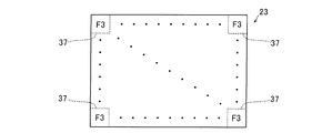
また、画像処理部8は、図9に示すように、除去画像23を複数の区画領域37に分割して、区画領域37内に含まれる画素の輝度変化量F2の値を平滑化する。区画領域37の大きさは、特に制限はないが、たとえば16×16画素などである。画像処理部8は、16×16画素の区画領域37内の各画素の輝度変化量F2の加算平均を行い、加算平均値F3を得る。そして、画像処理部8は、区画領域37内の各画素の輝度変化量を加算平均値F3とする。つまり、16×16画素の区画領域37内の各画素には、共通の輝度変化量F3が与えられる。輝度変化量F3は、区画領域37毎に取得される。
画像処理部8は、区画領域37毎に算出した輝度変化量F3に応じて、第3高調波成分33を除去する平坦領域34と平坦領域34以外の領域35(第3高調波成分33を除去しない領域)とを識別する。すなわち、画像処理部8は、輝度変化量F3が変化量閾値未満の場合に平坦領域34とし、輝度変化量F3が変化量閾値以上の場合に平坦領域34以外の領域35とする。各区画領域37(16×16画素)内の画素は共通の輝度変化量F3であるので、画像処理部8は、各区画領域37を単位として、輝度変化量F3の閾値判定(平坦領域34か否かの判断)を行う。なお、除去画像23を複数の区画領域37に分割せずに、除去画像23の画素毎の輝度変化量F2について閾値判定を行ってもよい。
以上の処理の結果、画像処理部8は、輝度変化量F3が変化量閾値未満の平坦領域34については、除去画像23から第3高調波成分33を除去した第3高調波除去画像24を出力する。輝度変化量F3が変化量閾値以上の領域(平坦領域34以外の領域)については、画像処理部8は、除去画像23をそのまま出力する。すなわち、図10に示すように、第1除去処理の場合、画像処理部8は、第3高調波除去画像24(平坦領域34)と除去画像23(領域35)との合成画像を作成し、作成した合成画像をX線処理画像22として出力する。この場合、領域35には、第3高調波成分33に起因するモアレパターンMPが残存することになるが、上記の通り輝度変化量が大きいため画像の視認性にほとんど影響しない。図10では、便宜的に、第3高調波成分33に起因する僅かに残存したモアレパターンMPを示す点線部を領域35に図示している。
(X線撮影装置の処理動作)
次に、図11を参照して、X線撮影装置100の処理動作を説明する。
次に、図11を参照して、X線撮影装置100の処理動作を説明する。
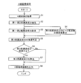
図11のステップS1において、X線画像21が取得される。まず、図1に示した制御部7が、予め設定された撮影条件に従ってX線照射部1からX線を被検体Pに照射させる。被検体Pを透過したX線は、X線検出部2により検出され、画像処理部8が、X線検出部2からX線画像21(図2参照)を取得する。
ステップS2において、画像処理部8は、X線画像21に対して1次元のフーリエ変換を行い、得られた周波数スペクトル(図3参照)から第1高調波成分31および第2高調波成分32を抽出する。
ステップS3において、画像処理部8は、抽出した第1高調波成分31および第2高調波成分32をX線画像21から除去し、第1高調波成分31および第2高調波成分32が除去された除去画像23(図5参照)を取得する。
また、ステップS3と並行して、画像処理部8は、ステップS4において、第1高調波成分31のピーク周波数に基づいて、第3高調波成分33のピーク周波数の推定値Eを算出する。
そして、ステップS5において、除去画像23に対して1次元のフーリエ変換を行い、得られた周波数スペクトル(図4参照)のうち、推定値Eを含む周波数範囲Rにおいて、第3高調波成分33の強度判定を行う。すなわち、画像処理部8は、周波数範囲Rにおいて隣接する周波数区分に対するスペクトルの相対強度が閾値TH以上か否かの判定を行う。
ステップS6において、画像処理部8は、第3高調波成分33の強度判定結果に応じて、第3高調波成分33を除去するか否かを判断する。すなわち、画像処理部8は、第3高調波成分33が閾値TH以上の相対強度のピークを有するか否かに応じて、第3高調波成分33を除去する第1除去処理を行うか、第3高調波成分33を除去しない第2除去処理を行うかを判断する。
第3高調波成分33が閾値TH以上の相対強度のピークを有する場合、画像処理部8は、ステップS7において、第3高調波成分33を除去する。すなわち、画像処理部8は、第1高調波成分31および第2高調波成分32が除去された除去画像23に対して、第3高調波成分33を除去することにより、第1除去処理を実行する。
画像処理部8は、上記の通り、第3高調波成分33を除去画像23から減算することにより、第3高調波除去画像24を取得するとともに、除去画像23中から輝度変化量F3を算出し、輝度変化量F3の閾値判定を行うことにより、平坦領域34を抽出する。そして、画像処理部8は、平坦領域34について第3高調波除去画像24を出力し、平坦領域34以外の領域については除去画像23をそのまま出力した合成画像を、X線処理画像22(図10参照)として作成する。
一方、第3高調波成分33の相対強度が閾値TH未満の場合、画像処理部8は、ステップS7をスキップしてステップS8に進む。この場合、画像処理部8は、第1高調波成分31および第2高調波成分32が除去された除去画像23を、X線処理画像22(図5参照)とする。つまり、第3高調波成分33の相対強度が閾値TH未満の場合、画像処理部8は、ステップS7をスキップすることにより、第3高調波成分33を除去しない第2除去処理を実行することになる。
ステップS8において、画像処理部8は、作成したX線処理画像22を表示部9に表示(出力)するとともに、記憶部11に記憶する。画像処理部8がステップS7を実行した場合(第3高調波成分33が閾値TH以上の相対強度のピークを有する場合)、出力されるX線処理画像22は、第1高調波成分31および第2高調波成分32が除去されるとともに、平坦領域34について第3高調波成分33が除去された合成画像(図10参照)となる。また、画像処理部8がステップS7を実行しなかった場合(第3高調波成分33の相対強度が閾値未満の場合)、出力されるX線処理画像22は、第3高調波成分33は除去せずに第1高調波成分31および第2高調波成分32が除去された除去画像23となる。
(実施形態の効果)
本実施形態では、以下のような効果を得ることができる。
本実施形態では、以下のような効果を得ることができる。
本実施形態では、上記のように、X線画像21のうちからモアレパターンMPを構成する高調波成分を抽出し、第1高調波成分31よりも高次の第3高調波成分33(3次の高次高調波成分)の強度に応じて、除去処理の内容を変更する画像処理部8を設ける。これにより、第3高調波成分33を除去することによる分解能の劣化の影響と、除去しない場合のモアレパターンMPの映り込みによる画質の劣化の影響とを勘案して、第3高調波成分33を除去するか否かを個々のX線画像21中の第3高調波成分33の強度に応じて変更することができる。その結果、除去する必要がない第3高調波成分33を除去しないことが可能となるので、モアレパターンMPの高調波成分の除去によってX線画像21の分解能を不必要に劣化させることを抑制することができる。
また、本実施形態では、上記のように、第3高調波成分33(高次高調波成分)の強度に応じて、第3高調波成分33および第3高調波成分33よりも低次の高調波成分(第1高調波成分31および第2高調波成分32)を除去する第1除去処理と、第3高調波成分33を除去せずに第3高調波成分33よりも低次の高調波成分を除去する第2除去処理とを切り替える。これにより、第3高調波成分33の強度が高い場合には第1除去処理によって第3高調波成分33を除去することができ、第3高調波成分33の強度が高くない場合には第2除去処理によって第3高調波成分33を残しておくことができる。また、除去処理を切り替える構成であっても、第3高調波成分33よりも低次の高調波成分は除去することができるので、モアレパターンMPの映り込みを効果的に除去することができる。
また、上記構成により、相対的に映り込みの影響の大きい第1高調波成分31および第2高調波成分32を確実に除去しつつ、第3高調波成分33については、強度に応じてケースバイケースで除去するか否かを選択することができる。その結果、モアレパターンMPの除去処理に起因する分解能の低下を効果的に抑制しつつ、モアレパターンMPの映り込みを効果的に除去することが可能となる。
特に、低い周波数成分には、モアレパターンMP以外の本来の画像情報が高周波成分と比較して多く含まれることから、上記実施形態で例示したように、第3高調波成分33(約1.29[lp/mm])が第1高調波成分31(約2.0[lp/mm])よりも低い周波数領域に現れる場合、第3高調波成分33を除去する場合の分解能低下が顕著である。このため、第3高調波成分33については強度に応じて除去するか否かを選択することによって、第3高調波成分33を一律で除去する構成と比較して、分解能低下を効果的に抑制することが可能となる。
また、本実施形態では、上記のように、第3高調波成分33が近傍の周波数成分と比較して閾値TH以上の相対強度のピークを有する場合に、第1除去処理を行い、第3高調波成分33が閾値TH未満の相対強度のピークを有する場合に、第2除去処理を行う。これにより、第3高調波成分33の強度に応じた除去の必要性を、閾値THを用いて容易に判断することができる。そして、適切な閾値THを設定することによって、容易に、第3高調波成分33を除去する第1除去処理と第3高調波成分33を除去しない第2除去処理とを必要性に応じて切り替えることが可能となる。
また、本実施形態では、上記のように、画像処理部8を、閾値THの設定値を変更可能に構成する。これにより、たとえば装置構成が変更された場合や、仕様の異なるX線撮影装置100の間においても、閾値THの設定値を変更するだけで画像処理部8を共通化することができるとともに、閾値THの最適化を行うことが容易となる。
また、本実施形態では、上記のように、第3高調波成分33よりも低次の高調波成分(第1高調波成分31および第2高調波成分32)が除去された除去画像23に対して、第3高調波成分33の抽出を行い、第3高調波成分33の強度に応じて除去画像23に対する除去処理の内容を変更するように画像処理部8を構成する。これにより、低次の高調波成分を除去した後で第3高調波成分33が抽出されるので、低次の高調波成分の一部を第3高調波成分33として誤認識したり、低次の高調波成分に紛れて第3高調波成分33を見逃したりすることを抑制することができる。その結果、より確実に第3高調波成分33を抽出して適切な除去処理を実行することができる。
また、本実施形態では、上記のように、第3高調波成分33のピーク周波数の推定値Eを含む周波数範囲Rにおいて第3高調波成分33の抽出を行うように画像処理部8を構成し、周波数範囲Rの設定値を変更可能にする。これにより、グリッド3のピッチに誤差が存在する場合でも、ピーク周波数の推定値Eを含む周波数範囲Rにおいて第3高調波成分33の抽出を行うことにより、より確実に第3高調波成分33が抽出できるようになる。また、周波数範囲Rの設定値を変更可能にすることによって、たとえば装置構成が変更された場合や、仕様の異なるX線撮影装置の間においても、周波数範囲Rの設定値を変更するだけで画像処理部8を共通化することができるようになる。
(変形例)
なお、今回開示された実施形態は、すべての点で例示であって制限的なものではないと考えられるべきである。本発明の範囲は、上記した実施形態の説明ではなく請求の範囲によって示され、さらに請求の範囲と均等の意味および範囲内でのすべての変更(変形例)が含まれる。
なお、今回開示された実施形態は、すべての点で例示であって制限的なものではないと考えられるべきである。本発明の範囲は、上記した実施形態の説明ではなく請求の範囲によって示され、さらに請求の範囲と均等の意味および範囲内でのすべての変更(変形例)が含まれる。
たとえば、上記実施形態では、被検体が人である例を示したが、本発明はこれに限られない。本発明では、被検体は、人以外の生物であってもよいし、物であってもよい。たとえば、本発明のX線撮影装置を、レントゲン装置などの医用機器以外の、X線検査装置(非破壊検査装置)などの産業用機器に用いてもよい。また、本発明のX線撮影装置を、分析機器などに用いてもよい。
また、上記実施形態では、横臥されている被検体を撮影する例を示したが、本発明はこれに限られない。本発明では、起きている状態(立位)の被検体を撮影してもよい。
また、上記実施形態では、3次の高次高調波成分である第3高調波成分33の強度に応じて、除去処理の内容を変更する構成の例を示したが、本発明はこれに限られない。本発明では、2次の高次高調波成分である第2高調波成分32の強度に応じて、除去処理の内容を変更してもよい。その場合、第2高調波成分32は、特許請求の範囲の「高次高調波成分」の一例である。モアレパターンの映り込みは、X線撮影装置100の装置構成によって異なることから、第2高調波成分32を除去するか否かをケースバイケースで強度に応じて判断した方がよい場合もあり得る。これは、上記実施形態で説明したケースよりもモアレパターンの映り込みが弱く、第3高調波成分33を無視できるようなケースである。この場合には、上記実施形態における一連の処理を第2高調波成分32に適用すればよい。すなわち、上記実施形態において「第3高調波成分33」を「第2高調波成分32」に読み替え、除去画像23については第1高調波成分31のみを除去した画像とすればよい。
また、上記実施形態では、第3高調波成分33(高次高調波成分)を抽出し、抽出した第3高調波成分33を除去画像23から減算することにより、第3高調波成分33を除去した例を示したが、本発明はこれに限られない。本発明では、たとえば、周波数スペクトルにおいて、抽出した第3高調波成分33のピーク強度を低減することにより、第3高調波成分33を部分的に除去(抑制)するだけでもよい。
また、上記実施形態では、第3高調波成分33(高次高調波成分)を除去する場合に、除去画像23のうち輝度変化の小さい平坦領域34に対して第3高調波成分33を除去する構成の例を示したが、本発明はこれに限られない。本発明では、第3高調波成分33(高次高調波成分)を除去する場合に、除去画像23の全体に対して一括して第3高調波成分33を除去してもよい。
また、上記実施形態では、第1高調波成分31、第2高調波成分32および第3高調波成分33を除去する第1除去処理と、第3高調波成分33を除去せずに第1高調波成分31および第2高調波成分32を除去する第2除去処理とを切り替える構成の例を示したが、本発明はこれに限られない。本発明では、たとえば、第3高調波成分33を完全に除去する第1除去処理と、第3高調波成分33のピーク強度を低減する第2除去処理とを切り替えてもよい。また、第1除去処理および第2除去処理以外の除去処理をさらに追加して、3つ以上の除去処理の間で切替を行ってもよい。
また、上記実施形態では、第3高調波成分33(高次高調波成分)が近傍の周波数成分と比較して閾値TH以上の相対強度のピークを有する場合に、第3高調波成分33を除去した例を示したが、本発明はこれに限られない。本発明では、相対強度ではなく、第3高調波成分33のピーク強度(絶対強度)が所定の閾値以上となる場合に、第3高調波成分33を除去してもよい。
また、上記実施形態では、除去画像23に対して、第3高調波成分33(高次高調波成分)の抽出および除去処理を行う構成の例を示したが、本発明はこれに限られない。本発明では、除去画像23ではなく、X線画像21に対して第3高調波成分33の抽出を行ってもよい。すなわち、X線画像21に対して第1高調波成分31、第2高調波成分32および第3高調波成分33の抽出をまとめて行い、第3高調波成分33の強度に応じた除去処理を第1高調波成分31、第2高調波成分32の除去処理と一緒にまとめて行ってもよい。
また、上記実施形態では、第3高調波成分33(高次高調波成分)の抽出を行うための周波数範囲Rの設定値を変更可能に構成した例を示したが、本発明はこれに限られない。本発明では、周波数範囲Rの設定値を固定値としてもよい。
また、上記実施形態では、第3高調波成分33(高次高調波成分)の相対強度の閾値THの設定値を変更可能に構成した例を示したが、本発明はこれに限られない。本発明では、閾値THの設定値を固定値としてもよい。
また、上記実施形態では、説明の便宜上、本発明のX線撮影装置の処理を処理フローに沿って順番に処理を行うフロー駆動型のフローチャートを用いて説明したが、本発明はこれに限られない。本発明では、処理動作を、イベント単位で処理を実行するイベント駆動型(イベントドリブン型)の処理により行ってもよい。この場合、完全なイベント駆動型で行ってもよいし、イベント駆動およびフロー駆動を組み合わせて行ってもよい。
1 X線照射部
2 X線検出部
3 グリッド
8 画像処理部
21 X線画像
22 X線処理画像
23 除去画像
31 第1高調波成分
32 第2高調波成分(高次高調波成分)
33 第3高調波成分(高次高調波成分)
100 X線撮影装置
E ピーク周波数の推定値
MP モアレパターン
P 被検体
R 周波数範囲
TH 閾値
2 X線検出部
3 グリッド
8 画像処理部
21 X線画像
22 X線処理画像
23 除去画像
31 第1高調波成分
32 第2高調波成分(高次高調波成分)
33 第3高調波成分(高次高調波成分)
100 X線撮影装置
E ピーク周波数の推定値
MP モアレパターン
P 被検体
R 周波数範囲
TH 閾値
Claims (7)
- 被検体にX線を照射するX線照射部と、
前記被検体を透過したX線を検出するX線検出部と、
前記X線検出部の検出面側に配置され、散乱したX線を除去するグリッドと、
前記X線検出部により得られたX線画像に映り込んだ前記グリッドに起因するモアレパターンの除去処理を行い、除去処理後のX線処理画像を出力する画像処理部とを備え、
前記画像処理部は、前記X線画像のうちから前記モアレパターンを構成する高調波成分を抽出し、1次の高調波成分としての第1高調波成分よりも高次の2次または3次の高次高調波成分の強度に応じて、前記除去処理の内容を変更するように構成されている、X線撮影装置。 - 前記画像処理部は、前記高次高調波成分の強度に応じて、
前記高次高調波成分および前記高次高調波成分よりも低次の高調波成分を除去する第1除去処理と、
前記高次高調波成分を除去せずに前記高次高調波成分よりも低次の高調波成分を除去する第2除去処理とを切り替えるように構成されている、請求項1に記載のX線撮影装置。 - 前記高次高調波成分は第3高調波成分であり、
前記第1除去処理は、第1高調波成分、第2高調波成分および第3高調波成分を除去する除去処理であり、
前記第2除去処理は、前記第3高調波成分を除去せずに第1高調波成分および第2高調波成分を除去する除去処理である、請求項2に記載のX線撮影装置。 - 前記画像処理部は、
前記高次高調波成分が近傍の周波数成分と比較して閾値以上の相対強度のピークを有する場合に、前記第1除去処理を行い、
前記高次高調波成分が前記閾値未満の相対強度のピークを有する場合に、前記第2除去処理を行うように構成されている、請求項2または3に記載のX線撮影装置。 - 前記画像処理部は、前記閾値の設定値を変更可能に構成されている、請求項4に記載のX線撮影装置。
- 前記画像処理部は、前記高次高調波成分よりも低次の高調波成分が除去された除去画像に対して、前記高次高調波成分の抽出を行い、前記高次高調波成分の強度に応じて前記除去画像に対する前記除去処理の内容を変更するように構成されている、請求項1~5のいずれか1項に記載のX線撮影装置。
- 前記画像処理部は、前記高次高調波成分のピーク周波数の推定値を含む周波数範囲において前記高次高調波成分の抽出を行うように構成され、
前記画像処理部は、前記周波数範囲の設定値を変更可能に構成されている、請求項1~6のいずれか1項に記載のX線撮影装置。
Priority Applications (2)
| Application Number | Priority Date | Filing Date | Title |
|---|---|---|---|
| PCT/JP2016/053852 WO2017138097A1 (ja) | 2016-02-09 | 2016-02-09 | X線撮影装置 |
| JP2017566449A JP6677263B2 (ja) | 2016-02-09 | 2016-02-09 | X線撮影装置 |
Applications Claiming Priority (1)
| Application Number | Priority Date | Filing Date | Title |
|---|---|---|---|
| PCT/JP2016/053852 WO2017138097A1 (ja) | 2016-02-09 | 2016-02-09 | X線撮影装置 |
Publications (1)
| Publication Number | Publication Date |
|---|---|
| WO2017138097A1 true WO2017138097A1 (ja) | 2017-08-17 |
Family
ID=59563007
Family Applications (1)
| Application Number | Title | Priority Date | Filing Date |
|---|---|---|---|
| PCT/JP2016/053852 Ceased WO2017138097A1 (ja) | 2016-02-09 | 2016-02-09 | X線撮影装置 |
Country Status (2)
| Country | Link |
|---|---|
| JP (1) | JP6677263B2 (ja) |
| WO (1) | WO2017138097A1 (ja) |
Cited By (2)
| Publication number | Priority date | Publication date | Assignee | Title |
|---|---|---|---|---|
| JP2019118198A (ja) * | 2017-12-27 | 2019-07-18 | 三菱重工サーマルシステムズ株式会社 | 制御装置、制御方法及びプログラム |
| US20240027632A1 (en) * | 2022-07-20 | 2024-01-25 | Canon Kabushiki Kaisha | Image processing apparatus, image processing method, radiation imaging apparatus, and storage medium |
Citations (4)
| Publication number | Priority date | Publication date | Assignee | Title |
|---|---|---|---|---|
| JP2005052553A (ja) * | 2003-08-07 | 2005-03-03 | Canon Inc | 放射線画像処理方法及び装置並びにグリッドの選別方法及び装置 |
| JP2010240259A (ja) * | 2009-04-08 | 2010-10-28 | Shimadzu Corp | 放射線撮像装置 |
| WO2012143979A1 (ja) * | 2011-04-22 | 2012-10-26 | 株式会社島津製作所 | X線診断装置およびx線診断用プログラム |
| JP2014008069A (ja) * | 2012-06-27 | 2014-01-20 | Shimadzu Corp | X線診断装置 |
-
2016
- 2016-02-09 JP JP2017566449A patent/JP6677263B2/ja active Active
- 2016-02-09 WO PCT/JP2016/053852 patent/WO2017138097A1/ja not_active Ceased
Patent Citations (4)
| Publication number | Priority date | Publication date | Assignee | Title |
|---|---|---|---|---|
| JP2005052553A (ja) * | 2003-08-07 | 2005-03-03 | Canon Inc | 放射線画像処理方法及び装置並びにグリッドの選別方法及び装置 |
| JP2010240259A (ja) * | 2009-04-08 | 2010-10-28 | Shimadzu Corp | 放射線撮像装置 |
| WO2012143979A1 (ja) * | 2011-04-22 | 2012-10-26 | 株式会社島津製作所 | X線診断装置およびx線診断用プログラム |
| JP2014008069A (ja) * | 2012-06-27 | 2014-01-20 | Shimadzu Corp | X線診断装置 |
Cited By (3)
| Publication number | Priority date | Publication date | Assignee | Title |
|---|---|---|---|---|
| JP2019118198A (ja) * | 2017-12-27 | 2019-07-18 | 三菱重工サーマルシステムズ株式会社 | 制御装置、制御方法及びプログラム |
| US20240027632A1 (en) * | 2022-07-20 | 2024-01-25 | Canon Kabushiki Kaisha | Image processing apparatus, image processing method, radiation imaging apparatus, and storage medium |
| JP7551703B2 (ja) | 2022-07-20 | 2024-09-17 | キヤノン株式会社 | 画像処理装置、画像処理方法、およびプログラム |
Also Published As
| Publication number | Publication date |
|---|---|
| JP6677263B2 (ja) | 2020-04-08 |
| JPWO2017138097A1 (ja) | 2018-11-22 |
Similar Documents
| Publication | Publication Date | Title |
|---|---|---|
| US9311695B2 (en) | Image processing method and radiographic apparatus using the same | |
| JP5641148B2 (ja) | 画像処理装置およびそれを備えた放射線撮影装置 | |
| KR20110074467A (ko) | 정보 처리 장치, 처리 방법 및 컴퓨터 판독가능한 기억 매체 | |
| WO2014050638A1 (ja) | 画像処理装置、プログラム及び画像処理方法 | |
| JP2017060737A (ja) | 人工的ノイズのない伝送画像を作成する処理 | |
| JP5527481B2 (ja) | X線診断装置およびx線診断用プログラム | |
| JP6677263B2 (ja) | X線撮影装置 | |
| JPWO2011074471A1 (ja) | X線画像診断装置、x線露出制御方法及びプログラム | |
| US8374417B2 (en) | Image processing method and radiographic apparatus using the same | |
| JP2017104329A (ja) | X線診断装置およびx線ct装置 | |
| WO2018074459A1 (ja) | 画像処理装置、画像処理方法及び画像処理プログラム | |
| JP4986467B2 (ja) | 医用画像表示装置 | |
| JP2011255032A (ja) | 画像処理方法およびそれを用いた放射線撮影装置 | |
| JP2011019591A (ja) | X線撮影装置、x線検出器における欠損画素の補間方法、および、x線検出器における欠損マップの作成方法 | |
| US9480451B2 (en) | X-ray image processing apparatus, X-ray diagnostic apparatus, and X-ray image processing method | |
| JP7284103B2 (ja) | 画像処理装置、画像処理方法及び画像処理プログラム | |
| JP5821790B2 (ja) | X線診断装置 | |
| US11013485B2 (en) | Method for dose reduction in an X-ray device taking account of a later display; imaging system; computer program; and data carrier | |
| JP5302838B2 (ja) | 画像処理装置、画像処理方法、画像処理プログラム、および、x線画像撮影装置 | |
| US10217215B2 (en) | Method for adapting the brightness of an X-ray image, X-ray device, computer program and data medium | |
| WO2022176280A1 (ja) | X線撮影装置、画像処理装置、および、画像処理方法 | |
| JP2006230512A (ja) | X線画像診断装置及び画像処理方法並びにプログラム | |
| JPWO2016021417A1 (ja) | X線ct装置、データ処理装置及び投影データ生成方法 | |
| HK40037196A (en) | Image processing device, image processing method, and image processing program | |
| JP2016209121A (ja) | X線撮影装置、x線画像処理装置、x線画像処理方法、および、x線画像処理プログラム |
Legal Events
| Date | Code | Title | Description |
|---|---|---|---|
| 121 | Ep: the epo has been informed by wipo that ep was designated in this application |
Ref document number: 16889799 Country of ref document: EP Kind code of ref document: A1 |
|
| WWE | Wipo information: entry into national phase |
Ref document number: 2017566449 Country of ref document: JP |
|
| NENP | Non-entry into the national phase |
Ref country code: DE |
|
| 122 | Ep: pct application non-entry in european phase |
Ref document number: 16889799 Country of ref document: EP Kind code of ref document: A1 |