以下、本開示に係る超音波発振の実施の形態を、図面に基づいて説明する。但し、以下に説明する実施の形態は、実施形態を例示するものであって、本開示に係る超音波発振装置1を以下に説明する具体的構成に限定するものではない。実施にあたっては、実施形態に応じた具体的構成が適宜採用され、また、種々の改良や変形が行われてよい。
Hereinafter, embodiments of ultrasonic oscillation according to the present disclosure will be described with reference to the drawings. However, the embodiment described below exemplifies the embodiment, and the ultrasonic oscillation device 1 according to the present disclosure is not limited to the specific configuration described below. In implementation, the specific structure according to embodiment is employ | adopted suitably, and various improvement and deformation | transformation may be performed.
<システム構成>
図1は、本実施形態に係る超音波発振装置1の概略を示す図である。本実施形態に係る超音波発振装置1は、超音波を用いて生体8内の対象9を加熱することによる治療および治療の状況確認を効率化することによって、治療者(ユーザー)の負担を軽減し、また、従来に比べて精度の高いスキャン・加熱を可能とするものである。
<System configuration>
FIG. 1 is a diagram showing an outline of an ultrasonic oscillator 1 according to this embodiment. The ultrasonic oscillating device 1 according to the present embodiment reduces the burden on the therapist (user) by increasing the efficiency of the treatment and the confirmation of the treatment status by heating the object 9 in the living body 8 using ultrasonic waves. In addition, scanning and heating can be performed with higher accuracy than in the prior art.
本実施形態に係る超音波発振装置1は、略半球の形状を有するメンブレン11と、メンブレン11に設置された複数の超音波振動子12(transducer)からなる超音波振動子アレイ13と、メンブレン11外面に設置されたアクチュエーター14と、メンブレン11等が設置される筐体15と、筐体15上端に設けられてユーザーに把持されるハンドル16と、ユーザーがハンドル16を把持した状態で操作可能なレバー17と、超音波振動子12およびアクチュエーター14等を制御する制御部10と、ハンドル16上端に設置されて制御部10から出力された画像データ等を表示する表示装置18と、外部装置と接続されるケーブル19と、を備える。ケーブル19には、通信ケーブル、電力ケーブル、超音波振動子12の冷却のための水冷パイプ、等が内包されてよい。但し、超音波発振装置1の具体的なハードウェア構成に関しては、実施の態様に応じて適宜省略や置換、追加が可能である。例えば、表示装置は、超音波発振装置1の構成に含まれず、有線または無線で外部に接続された表示装置が用いられることとしてもよい。また、制御部についても、有線または無線で外部に接続された制御部が用いられてよいことは同様である。
The ultrasonic oscillator 1 according to the present embodiment includes a membrane 11 having a substantially hemispherical shape, an ultrasonic transducer array 13 including a plurality of ultrasonic transducers 12 (transducers) installed on the membrane 11, and the membrane 11. An actuator 14 installed on the outer surface, a casing 15 on which the membrane 11 and the like are installed, a handle 16 provided at the upper end of the casing 15 and gripped by the user, and operable with the user gripping the handle 16 A control unit 10 that controls the lever 17, the ultrasonic transducer 12, the actuator 14, and the like, a display device 18 that is installed at the upper end of the handle 16 and displays image data and the like output from the control unit 10, and a connection to an external device Cable 19 to be provided. The cable 19 may include a communication cable, a power cable, a water cooling pipe for cooling the ultrasonic transducer 12, and the like. However, the specific hardware configuration of the ultrasonic oscillator 1 can be appropriately omitted, replaced, or added depending on the embodiment. For example, the display device is not included in the configuration of the ultrasonic oscillation device 1, and a display device connected to the outside by wire or wireless may be used. Similarly, the control unit connected to the outside by wire or wireless may be used.
ユーザーは、ハンドル16を把持して、超音波発振装置1を、加熱対象9を含む生体8の表面において自在に移動させることが出来る。また、ユーザーは、ハンドル16を把持した状態で、表示装置18による表示内容を確認しながら、レバー17を操作することで、加熱対象9への加熱(超音波振動子12からの発振)を、制御部10に対して指示することが出来る。
The user can grip the handle 16 and freely move the ultrasonic oscillator 1 on the surface of the living body 8 including the heating target 9. In addition, the user operates the lever 17 while confirming the display content by the display device 18 while holding the handle 16, thereby heating the heating target 9 (oscillation from the ultrasonic vibrator 12). An instruction can be given to the control unit 10.
図2は、本実施形態に係る超音波発振装置1が備えるメンブレン11の概略を示す図である。メンブレン11は、超音波発振装置1を加熱対象9に向けた状態で加熱対象9に対して凹面を形成する凹部111と、凹部111の開口を塞ぎ加熱対象9を含む生体8に接触する接触部112と、を有することで、全体として略半球の形状を有する部材である。但し、本実施形態において、凹部111は略半球の形状を有しているが、凹部111の形状にはその他の形状が採用されてもよい。凹部111の形状には、例えば、円錐、円錐台、半回転楕円体およびこれらに近似する形状等が採用されてもよい。
FIG. 2 is a diagram showing an outline of the membrane 11 provided in the ultrasonic oscillation device 1 according to the present embodiment. The membrane 11 includes a concave portion 111 that forms a concave surface with respect to the heating target 9 in a state where the ultrasonic oscillation device 1 is directed to the heating target 9, and a contact portion that closes the opening of the concave portion 111 and contacts the living body 8 including the heating target 9. 112, and a member having a substantially hemispherical shape as a whole. However, in the present embodiment, the recess 111 has a substantially hemispherical shape, but other shapes may be adopted as the shape of the recess 111. As the shape of the recess 111, for example, a cone, a truncated cone, a semi-spheroid, and a shape similar to these may be employed.
メンブレン11の外殻は弾性素材によって形成されており、内部にはゲルが満たされている。このため、メンブレン11の凹部111および接触部112は変形可能である。なお、内部を満たす物質はメンブレン11の凹部111の変形に追従可能な物質であればよく、例えば液体であってもよい。また、メンブレン11およびメンブレン11の内部を満たす物質は、超音波の伝搬のために、超音波の吸収が少なく、伝搬速度が生体8と差が少なく、濃淡の生じにくい均一な媒質であることが好ましい。
The outer shell of the membrane 11 is made of an elastic material, and the inside is filled with gel. For this reason, the recessed part 111 and the contact part 112 of the membrane 11 are deformable. The substance filling the inside may be a substance that can follow the deformation of the concave portion 111 of the membrane 11, and may be, for example, a liquid. In addition, the membrane 11 and the substance filling the inside of the membrane 11 are a uniform medium that hardly absorbs ultrasonic waves, has a small difference in propagation speed from the living body 8, and is less likely to cause shading due to the propagation of ultrasonic waves. preferable.
また、メンブレン11の凹部111の内側面には、複数の超音波振動子12が並べて保持されており、これによって、加熱対象9に対する凹面に沿って複数の超音波振動子12が配置され、凹状の超音波振動子アレイ13が構成される。即ち、本実施形態において、メンブレン11は、超音波振動子12を保持する保持部としても機能する。但し、複数の超音波振動子12は、メンブレン11の凹部111の外側面に保持されてもよい。
In addition, a plurality of ultrasonic transducers 12 are held side by side on the inner surface of the concave portion 111 of the membrane 11, whereby the plurality of ultrasonic transducers 12 are arranged along the concave surface with respect to the heating object 9, and are concave. The ultrasonic transducer array 13 is configured. That is, in the present embodiment, the membrane 11 also functions as a holding unit that holds the ultrasonic transducer 12. However, the plurality of ultrasonic transducers 12 may be held on the outer surface of the recess 111 of the membrane 11.
アクチュエーター14(駆動部)は、メンブレン11に接続されて駆動することで、メンブレン11の凹部111を変形させる。本実施形態では、複数のリニアアクチュエーター14が、メンブレン11を取り囲む筐体15とメンブレン11とを接続するように設置され、制御部10による指示に従って夫々のリニアアクチュエーター14が駆動することで、凹部111が変形する。但し、本実施形態において示された駆動部の構成は一例であり、駆動部を用いて凹部111を変形させる手段は、本実施形態における例に限定されない。例えば、傘を開閉するための機構と同様の機構をメンブレン11の凹部111を取り囲むように設置し、これを1のアクチュエーターによって開閉させることで、凹部111を変形させることとしてもよい。また、駆動部は、筐体15に接続されていなくても、凹部111を変形させることが出来る。
The actuator 14 (drive unit) is connected to the membrane 11 and driven to deform the concave portion 111 of the membrane 11. In the present embodiment, a plurality of linear actuators 14 are installed so as to connect the casing 15 surrounding the membrane 11 and the membrane 11, and each of the linear actuators 14 is driven in accordance with an instruction from the control unit 10. Is deformed. However, the configuration of the drive unit shown in the present embodiment is an example, and means for deforming the concave portion 111 using the drive unit is not limited to the example in the present embodiment. For example, a mechanism similar to the mechanism for opening and closing the umbrella may be installed so as to surround the concave portion 111 of the membrane 11, and the concave portion 111 may be deformed by opening and closing the same with an actuator. Further, even if the drive unit is not connected to the housing 15, the recess 111 can be deformed.
なお、本実施形態では、アクチュエーターを用いて凹部を変形させる例について説明しているが、凹部を変形させる方法には、その他の方法が採用されてもよい。例えば、メンブレン内部のゲル量を調整することによって凹部を変形させる方法が採用されてもよい。この場合、制御部10は、ゲル量と凹部の形状(例えば曲率)との対応関係を示したマップや関数を予め保持しておくことで、ゲル量の調整による凹部の変形を行うことが出来る。
In this embodiment, an example in which the concave portion is deformed by using the actuator has been described. However, other methods may be adopted as a method of deforming the concave portion. For example, a method of deforming the recess by adjusting the gel amount inside the membrane may be employed. In this case, the control unit 10 can perform deformation of the concave portion by adjusting the gel amount by holding in advance a map or a function indicating a correspondence relationship between the gel amount and the shape (for example, curvature) of the concave portion. .
また、本実施形態において、複数の超音波振動子12は、他の超音波振動子12から発振された超音波の直接波または反射波を感知する感知手段としても用いられる。複数の超音波振動子12は、他の超音波振動子12から発振された超音波の直接波または反射波を感知すると、感知された超音波の振幅、周波数および位相等に応じた感知信号を、制御部10に対して出力する。制御部10は、感知信号を受信すると、受信された感知信号のうち、反射波に基づく感知信号を用いて、加熱対象9を含む反射対象に係る三次元画像データを生成する。
In the present embodiment, the plurality of ultrasonic transducers 12 are also used as sensing means for sensing direct waves or reflected waves of ultrasonic waves oscillated from other ultrasonic transducers 12. When a plurality of ultrasonic transducers 12 senses a direct wave or a reflected wave of an ultrasonic wave oscillated from another ultrasonic transducer 12, a plurality of ultrasonic transducers 12 generate sensing signals corresponding to the detected ultrasonic wave amplitude, frequency, phase, and the like. To the control unit 10. When receiving the sensing signal, the control unit 10 generates three-dimensional image data relating to the reflecting object including the heating object 9 using the sensing signal based on the reflected wave among the received sensing signals.
但し、本実施形態では、超音波の発振用の超音波振動子12を感知用のセンサーとしても用いたが、感知用のセンサーは発振側振動子とは別に設けられてもよい。また、加熱のための発振および感知と、撮像のための発振および感知とは、同一の超音波振動子アレイを用いて行われてもよいし、別々に設けられた加熱用超音波振動子アレイと撮像用超音波振動子アレイとを用いて行われてもよい。加熱用超音波振動子アレイと撮像用超音波振動子アレイとが別々に設けられる場合には、加熱用超音波振動子アレイと撮像用超音波振動子アレイとは凹部111に積層されて設置されてもよいし、同一の層に分散配置されてもよい。
However, in the present embodiment, the ultrasonic oscillator 12 for ultrasonic oscillation is also used as a sensor for detection, but the sensor for detection may be provided separately from the oscillator on the oscillation side. Further, the oscillation and sensing for heating and the oscillation and sensing for imaging may be performed using the same ultrasonic transducer array, or the heating ultrasonic transducer array provided separately. And an ultrasonic transducer array for imaging. When the heating ultrasonic transducer array and the imaging ultrasonic transducer array are provided separately, the heating ultrasonic transducer array and the imaging ultrasonic transducer array are stacked and installed in the recess 111. Alternatively, they may be distributed in the same layer.
制御部10は、CPU(Central Processing Unit)、RAM(Random Access Memory)、ROM(Read Only Memory)、ストレージ(補助記憶装置)、通信インターフェース等(図示は省略する)を備えるコンピューターであり、ストレージから読み出されてRAMに展開されたプログラムやROMに格納されたプログラムをCPUが実行することで、後述する各種の制御を行う。但し、制御部10の具体的なハードウェア構成に関しては、実施の態様に応じて適宜省略や置換、追加が可能である。また、制御部10は、単一の装置に限定されない。制御部10は、所謂クラウドや分散コンピューティングの技術等を用いた、複数の装置によって実現されてよい。
The control unit 10 is a computer including a CPU (Central Processing Unit), a RAM (Random Access Memory), a ROM (Read Only Memory), a storage (auxiliary storage device), a communication interface (not shown), and the like. The CPU executes a program read out and expanded in the RAM or a program stored in the ROM to perform various controls described later. However, the specific hardware configuration of the control unit 10 can be appropriately omitted, replaced, or added according to the embodiment. Further, the control unit 10 is not limited to a single device. The control unit 10 may be realized by a plurality of devices using a so-called cloud or distributed computing technology.
制御部10は、超音波振動子12を制御して、超音波を発振させる。より具体的には、制御部10は、複数の超音波振動子12から発振させる超音波の焦点が加熱対象9の位置となる状態で、これらの超音波振動子12の夫々を制御して超音波を発振させ、加熱対象9を加熱する。ここで、制御部10は、複数の超音波振動子12の夫々を制御して超音波振動子12の夫々から発振される超音波の位相を調整することで、超音波による加熱位置の制御や、加熱のキャンセル等を行う。なお、位相制御によって加熱位置(焦点位置)を変える具体的な方法としては、夫々の超音波振動子12から出力される超音波の位相を異ならせることで、擬似的に発振点が異なるような状態とし、合成波の方向を制御する、超音波フェーズドアレイ技術を採用することが出来る。本実施形態において、制御部10は、夫々の超音波振動子12から出力される超音波の位相を制御することで、合成波の方向を制御し、加熱位置を調整する。
The control unit 10 controls the ultrasonic transducer 12 to oscillate ultrasonic waves. More specifically, the control unit 10 controls each of these ultrasonic transducers 12 in a state where the focal point of the ultrasonic waves oscillated from the plurality of ultrasonic transducers 12 is the position of the heating target 9. A sound wave is oscillated to heat the object 9 to be heated. Here, the control unit 10 controls each of the plurality of ultrasonic transducers 12 and adjusts the phase of the ultrasonic waves oscillated from each of the ultrasonic transducers 12, thereby controlling the heating position by the ultrasonic waves. , Cancel the heating, etc. As a specific method of changing the heating position (focal position) by phase control, the oscillation points differ in a pseudo manner by changing the phases of the ultrasonic waves output from the respective ultrasonic transducers 12. An ultrasonic phased array technology that controls the direction of the synthesized wave can be adopted. In this embodiment, the control part 10 controls the direction of a synthetic wave by controlling the phase of the ultrasonic wave output from each ultrasonic transducer | vibrator 12, and adjusts a heating position.
また、制御部10は、アクチュエーター14を制御してアクチュエーター14に凹部111を押し/引きさせることによって凹部111を変形させ、複数の超音波振動子12の夫々による超音波の発振方向を調整することで、複数の超音波振動子12から発振される超音波による加熱位置(焦点位置)を制御する。上述の通り、超音波を発振する複数の超音波振動子12は、メンブレン11の凹部111に設けられることで、超音波振動子アレイ13を構成している。このため、アクチュエーター14によって凹部111が変形すると、これに応じて複数の超音波振動子12は移動し、夫々の超音波振動子12による超音波の発振方向は変化する。本実施形態に係る超音波発振装置1では、このようにして凹部111を変形させることで、超音波の発振方向および加熱位置を調整可能としている。
Further, the control unit 10 controls the actuator 14 to cause the actuator 14 to push / pull the concave portion 111 to deform the concave portion 111 and adjust the oscillation direction of the ultrasonic waves by each of the plurality of ultrasonic transducers 12. Thus, the heating position (focus position) by the ultrasonic waves oscillated from the plural ultrasonic transducers 12 is controlled. As described above, the plurality of ultrasonic transducers 12 that oscillate ultrasonic waves are provided in the concave portion 111 of the membrane 11 to constitute the ultrasonic transducer array 13. For this reason, when the concave portion 111 is deformed by the actuator 14, the plurality of ultrasonic transducers 12 move in accordance with this, and the ultrasonic oscillation direction of each ultrasonic transducer 12 changes. In the ultrasonic oscillating device 1 according to the present embodiment, it is possible to adjust the ultrasonic oscillation direction and the heating position by deforming the concave portion 111 in this manner.
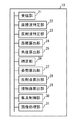
図3は、本実施形態に係る制御部10の機能構成の概略を示す図である。制御部10は、ストレージから読み出されてRAMに展開されたプログラムやROMに格納されたプログラムをCPUが実行することで、受信部21、直接波特定部22、反射波特定部23、距離算出部24、角度算出部25、補正部26、姿勢算出部27、反射点算出部28、接触面算出部29、焦点制御部30および画像処理部31として機能する。
FIG. 3 is a diagram illustrating an outline of a functional configuration of the control unit 10 according to the present embodiment. The control unit 10 causes the CPU to execute a program read from the storage and loaded in the RAM or a program stored in the ROM, whereby the receiving unit 21, the direct wave specifying unit 22, the reflected wave specifying unit 23, the distance calculation Functions as a unit 24, an angle calculation unit 25, a correction unit 26, a posture calculation unit 27, a reflection point calculation unit 28, a contact surface calculation unit 29, a focus control unit 30, and an image processing unit 31.
受信部21は、他の超音波振動子12から発振された超音波を感知した超音波振動子12から出力された感知信号を受信する。
The receiving unit 21 receives the sensing signal output from the ultrasonic transducer 12 that has sensed the ultrasonic wave oscillated from the other ultrasonic transducer 12.
直接波特定部22は、受信された感知信号に含まれる、直接波に係る感知信号を特定する。
The direct wave specifying unit 22 specifies a detection signal related to the direct wave included in the received detection signal.
反射波特定部23は、受信された感知信号に含まれる、反射波に係る感知信号を特定する。
The reflected wave identifying unit 23 identifies a sensing signal related to the reflected wave included in the received sensing signal.
距離算出部24は、直接波の発振から感知までの時間に基づいて、発振側振動子と感知側振動子との間の距離を算出し、また、反射波の発振から感知までの時間に基づいて、発振側振動子から感知側振動子までの反射波の経路長を更に算出する。ここで、距離算出部24は、発振から感知までの時間に伝搬速度を乗算することで距離を算出する。
The distance calculation unit 24 calculates the distance between the oscillation-side transducer and the sensing-side transducer based on the time from the oscillation of the direct wave to the sensing, and also based on the time from the oscillation of the reflected wave to the sensing. Thus, the path length of the reflected wave from the oscillation-side oscillator to the sensing-side oscillator is further calculated. Here, the distance calculation unit 24 calculates the distance by multiplying the time from oscillation to sensing by the propagation speed.
角度算出部25は、直接波に係る感知信号に基づいて、発振側振動子から発振の中心軸(メインローブの発振軸)および当該感知側振動子を見込む角を算出する。また、角度算出部25は、反射波に係る感知信号に基づいて、発振側振動子から発振の中心軸および反射点を見込む角を更に算出し、反射波の強度に基づいて、当該反射点からの当該感知側振動子への入射角を更に算出する。ここで、角度算出部25は、予め保持されている発振角度とスペクトルとの対応関係に基づいて、感知信号のスペクトルに対応するスペクトルを有する発振角度を算出することで、見込む角を算出する。なお、「見込む角」とは、あるポイント(他の振動子や反射点等の対象)が振動子の向きに伸びる発振の中心軸から何度ずれているかを示す角度であり、例えば、発振側振動子が発振の中心軸および対象を見込む角は、「発振側振動子の発振面を通る中心軸の方向(発振側振動子から発振された超音波が指向する中心方向)」と、「発振側振動子の発振面の中心と対象とを結ぶ線」と、がなす角度である。換言すれば、「見込む角」は、発振側振動子の発振面の中心を原点に、発振面の中心軸をz軸に選んだ球面座標系で対象を見たときの天頂角に等しい。また、角度算出部25は、感知側振動子が垂直に感知した場合の感知信号の推定強度と、実際に受信された感知信号の強度とを比較することで、入射角を算出する。
The angle calculation unit 25 calculates the angle at which the oscillation center axis (main lobe oscillation axis) and the sensing side oscillator are viewed from the oscillation side oscillator based on the sensing signal related to the direct wave. In addition, the angle calculation unit 25 further calculates an angle at which the oscillation center axis and the reflection point are expected from the oscillation-side vibrator based on the sensing signal related to the reflected wave, and from the reflection point based on the intensity of the reflected wave. The incident angle to the sensing-side transducer is further calculated. Here, the angle calculation unit 25 calculates an expected angle by calculating an oscillation angle having a spectrum corresponding to the spectrum of the sensing signal based on the correspondence relationship between the oscillation angle and the spectrum held in advance. Note that the “look angle” is an angle indicating how many times a certain point (an object such as another vibrator or a reflection point) deviates from the center axis of oscillation extending in the direction of the vibrator. The angle at which the transducer sees the central axis of oscillation and the target is the direction of the central axis that passes through the oscillation surface of the oscillation transducer (the central direction in which the ultrasonic wave oscillated from the oscillation transducer is directed) and “oscillation This is the angle formed by the line connecting the center of the oscillation surface of the side vibrator and the object. In other words, the “viewing angle” is equal to the zenith angle when the object is viewed in a spherical coordinate system in which the center of the oscillation surface of the oscillation-side oscillator is selected as the origin and the center axis of the oscillation surface is selected as the z-axis. The angle calculator 25 calculates the incident angle by comparing the estimated intensity of the sensing signal when the sensing-side transducer senses vertically with the intensity of the actually received sensing signal.
補正部26は、複数の超音波振動子12の相対的な位置関係を示す位置情報を、距離および見込む角を用いて補正する。
The correction unit 26 corrects the positional information indicating the relative positional relationship between the plurality of ultrasonic transducers 12 using the distance and the expected angle.
姿勢算出部27は、発振側振動子から発振の中心軸および第一の感知側振動子を見込む角と、発振側振動子から発振の中心軸および第二の感知側振動子を見込む角と、発振側振動子の位置情報と、第一の感知側振動子の位置情報と、第二の感知側振動子の位置情報とに基づいて、当該発振側振動子の向き(姿勢)を算出する。なお、ここでは第一の感知側振動子および第二の感知側振動子の2つの感知側振動子に係る情報(見込む角および位置情報)が姿勢の算出に用いられているが、姿勢の算出には、3以上の感知側振動子に係る情報(見込む角および位置情報)が用いられてもよく、その数は限定されない。
The attitude calculation unit 27 includes an angle at which the center axis of oscillation and the first sensing side oscillator are viewed from the oscillation side oscillator, an angle at which the center axis of oscillation and the second sensing side oscillator are viewed from the oscillation side oscillator, Based on the position information of the oscillation-side vibrator, the position information of the first sensing-side vibrator, and the position information of the second sensing-side vibrator, the direction (attitude) of the oscillation-side vibrator is calculated. Note that, here, information on the two sensing-side transducers of the first sensing-side transducer and the second sensing-side transducer (viewed angle and position information) is used to calculate the orientation. In this case, information related to three or more sensing-side vibrators (viewed angle and position information) may be used, and the number thereof is not limited.
反射点算出部28は、接触部112が生体8に接触する接触面上にある反射点の位置を示す反射点位置情報を、超音波振動子12の位置情報、超音波振動子12の向き、反射波の経路長、発振側振動子から発振の中心軸および反射点を見込む角および入射角に基づいて算出する。
The reflection point calculation unit 28 displays the reflection point position information indicating the position of the reflection point on the contact surface where the contact unit 112 contacts the living body 8, the position information of the ultrasonic transducer 12, the orientation of the ultrasonic transducer 12, Calculation is made based on the path length of the reflected wave, the angle at which the oscillation center axis and reflection point are expected from the oscillation-side oscillator, and the incident angle.
接触面算出部29は、接触部112が生体8に接触する接触面の形状を示す接触面形状情報を、複数の反射点位置情報を用いて算出する。
The contact surface calculation unit 29 calculates contact surface shape information indicating the shape of the contact surface with which the contact unit 112 contacts the living body 8 using a plurality of reflection point position information.
焦点制御部30は、複数の超音波振動子12の相対的な位置関係を示す位置情報、超音波振動子12の向き、および接触面形状情報に基づいて、超音波が各超音波振動子12から当該接触面を経て焦点位置に到達するまでの時間を算出し、算出結果に従って当該複数の超音波振動子12の夫々による超音波の位相(発振時刻)を調整することで、当該複数の超音波振動子12から発振される超音波による焦点位置を制御する。
The focus control unit 30 generates ultrasonic waves based on the positional information indicating the relative positional relationship among the plurality of ultrasonic transducers 12, the orientation of the ultrasonic transducers 12, and the contact surface shape information. The time from reaching the focal position through the contact surface is calculated, and the phases (oscillation times) of the ultrasonic waves by the ultrasonic transducers 12 are adjusted according to the calculation results, thereby The focal position by the ultrasonic wave oscillated from the sonic transducer 12 is controlled.
また、焦点制御部30は、複数の超音波振動子12の相対的な位置関係を示す位置情報および向きと、当該複数の超音波振動子12の目標位置および目標向きとを比較した結果に基づいて、アクチュエーター14を制御して凹部111を変形させ、複数の超音波振動子12の夫々による超音波の発振方向を調整することで、当該複数の超音波振動子12から発振される超音波による焦点位置を制御する。
Further, the focus control unit 30 is based on the result of comparing the position information and direction indicating the relative positional relationship of the plurality of ultrasonic transducers 12 with the target position and target direction of the plurality of ultrasonic transducers 12. By controlling the actuator 14 to deform the concave portion 111 and adjusting the oscillation direction of the ultrasonic waves by each of the plurality of ultrasonic transducers 12, the ultrasonic waves oscillated from the plurality of ultrasonic transducers 12 are adjusted. Control the focal position.
画像処理部31は、受信された感知信号のうち、反射波に基づく感知信号に基づいて、対象9を含む反射対象に係る画像データ(画像データの形式は限定されない。例えば、画像データは二次元画像データおよび三次元画像データの何れであってもよい)を生成し、出力する。また、画像処理部31は、画像データにおける対象9の位置と焦点位置とを照合し、当該焦点位置を対象9の位置に誘導する指示情報を生成し、出力する。
The image processing unit 31 is based on the sensing signal based on the reflected wave among the received sensing signals, and the image data related to the reflecting object including the object 9 (the format of the image data is not limited. For example, the image data is two-dimensional. Any of image data and 3D image data) may be generated and output. Further, the image processing unit 31 collates the position of the target 9 and the focal position in the image data, generates instruction information for guiding the focal position to the position of the target 9, and outputs it.
<装置の制御>
次に、本実施形態に係る超音波発振装置1において実行される制御を説明する。なお、本実施形態において説明される処理の具体的な内容および順序等は、実施する上での一例である。具体的な処理内容および順序等は、実施の態様に応じて適宜選択されてよい。
<Control of device>
Next, control executed in the ultrasonic oscillator 1 according to this embodiment will be described. Note that the specific contents and order of the processing described in the present embodiment are examples for implementation. Specific processing contents, order, and the like may be appropriately selected according to the embodiment.
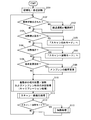
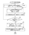
図4は、本実施形態における起動・運転処理の流れを示すフローチャートである。本フローチャートに示された処理は、超音波発振装置1の電源が投入されたことを契機として開始される。
FIG. 4 is a flowchart showing the flow of start-up / operation processing in the present embodiment. The processing shown in this flowchart is started when the power of the ultrasonic oscillator 1 is turned on.
ステップS101では、初期化及び自己診断が行われる。制御部10は、機器の自己診断を行い、超音波発振装置1が正常に動作することを確認する。そして、制御部10は、超音波発振装置1の起動に伴い、初期化のために予め用意されている制御信号をアクチュエーター14に対して出力することで、メンブレン11の凹部111の曲率が所定の初期値となるようにアクチュエーター14を制御する。
In step S101, initialization and self-diagnosis are performed. The control unit 10 performs self-diagnosis of the device and confirms that the ultrasonic oscillator 1 operates normally. And the control part 10 outputs the control signal prepared beforehand for initialization with respect to the actuator 14 with starting of the ultrasonic oscillation apparatus 1, and the curvature of the recessed part 111 of the membrane 11 is predetermined. The actuator 14 is controlled so as to have an initial value.
具体的には、制御部10は、アクチュエーター14を稼働させメンブレン11の凹部111の曲率変更を行い、また、超音波振動子12から発振される加熱用超音波の位相を設定することで、超音波振動子アレイ13によって超音波が発振された場合の焦点(加熱位置)を、初期位置に調整する。
Specifically, the control unit 10 operates the actuator 14 to change the curvature of the concave portion 111 of the membrane 11, and sets the phase of the heating ultrasonic wave oscillated from the ultrasonic transducer 12, thereby The focal point (heating position) when ultrasonic waves are oscillated by the acoustic transducer array 13 is adjusted to the initial position.
その後、超音波発振装置1はスキャンおよび加熱を行える運転状態に遷移し、処理はステップS102へ進む。運転状態の超音波発振装置1は、定期的に超音波振動子12の位置および姿勢、並びに接触面の形状を計測しながら、体内の構造を解析し、ユーザーに知らせる「検査・診断補助」と体内の臓器の動きに追従した加熱(焼灼)とを行う。
Thereafter, the ultrasonic oscillating device 1 transitions to an operation state in which scanning and heating can be performed, and the process proceeds to step S102. The ultrasonic oscillating device 1 in the operating state is “inspection / diagnosis assistance” that analyzes the structure of the body and informs the user while periodically measuring the position and posture of the ultrasonic transducer 12 and the shape of the contact surface. It performs heating (cauterization) following the movement of the internal organs.
ステップS102およびステップS103では、装置の異常チェックが行われ、異常が検出された場合、装置は縮退運転状態へ遷移するか、電源OFFされる。本実施形態では、スキャンと加熱を行える状態を「運転状態」と称し、全ての構成機器が正常に動作している場合を特に「通常運転状態」と称する。スキャン・加熱の対象や運用環境によっては、一部の機器(例えば、一部の超音波振動子12等)が不調であっても、スキャン・加熱に致命的不具合がない限り、スキャン・加熱を続けられることが望ましい場合もあり得る。この場合、超音波発振装置1は、一部の機能を停止してスキャン・加熱を行う縮退運転を行ってもよい。装置の異常チェックが完了すると、処理はステップS104へ進む。
In step S102 and step S103, an abnormality check is performed on the apparatus. If an abnormality is detected, the apparatus transitions to a degenerate operation state or is turned off. In the present embodiment, a state where scanning and heating can be performed is referred to as an “operating state”, and a case where all the component devices are operating normally is particularly referred to as a “normal operating state”. Depending on the target of scanning / heating and the operating environment, even if some devices (for example, some ultrasonic transducers 12) are malfunctioning, scanning / heating may be performed as long as there is no fatal failure in scanning / heating. It may be desirable to continue. In this case, the ultrasonic oscillator 1 may perform a degenerate operation in which some functions are stopped and scanning / heating is performed. When the apparatus abnormality check is completed, the process proceeds to step S104.
ステップS104からステップS107では、ユーザーによる操作に応じて、超音波発振装置1の動作モードが設定される。超音波発振装置1が運転状態(通常運転状態または縮退運転状態)にある間、ユーザーは、表示装置18に表示された画像を確認し、加熱を行って良い状態であると判断した場合には、レバー17を操作することで、加熱対象9への加熱(超音波振動子12からの発振)を、制御部10に対して指示する。ユーザーがレバー17を操作すると、制御部10には、加熱指示が入力される。なお、本実施形態では、レバー17の操作による加熱指示が例示されているが、ユーザーによる指示は、その他のインターフェースを介して行われてもよい。例えば、加熱開始ボタンおよび加熱停止ボタンを備えることで、ユーザーが加熱の開始と停止を指示可能としてもよい。
From step S104 to step S107, the operation mode of the ultrasonic oscillating device 1 is set according to the operation by the user. When the user confirms the image displayed on the display device 18 while the ultrasonic oscillator 1 is in the operation state (the normal operation state or the degenerate operation state), and determines that it is in a state where heating is possible, By operating the lever 17, the control unit 10 is instructed to heat the heating target 9 (oscillation from the ultrasonic vibrator 12). When the user operates the lever 17, a heating instruction is input to the control unit 10. In the present embodiment, the heating instruction by operating the lever 17 is illustrated, but the instruction by the user may be performed via another interface. For example, by providing a heating start button and a heating stop button, the user may be able to instruct the start and stop of heating.
制御部10は、ユーザーのレバー操作による加熱指示の入力があるか否かを判定する。ユーザーがレバー17を離したことによる加熱停止指示、または、後述する加熱処理において加熱位置と加熱対象9とのズレが所定の基準を超えた場合に発行される加熱停止指示(ステップS609を参照)が入力されたと判定された場合(ステップS104の「YES」)、動作モードは「スキャンのみモード」に設定される(ステップS105)。一方、加熱指示が入力されている(または、加熱開始指示が入力された)と判定された場合(ステップS106の「YES」)、動作モードは「スキャン+加熱モード」に設定される(ステップS107)。その後、処理はステップS108へ進む。
The control unit 10 determines whether or not there is a heating instruction input by a user's lever operation. A heating stop instruction when the user releases the lever 17 or a heating stop instruction issued when a deviation between the heating position and the heating target 9 exceeds a predetermined reference in the heating process described later (see step S609). Is determined to be input (“YES” in step S104), the operation mode is set to “scan only mode” (step S105). On the other hand, when it is determined that a heating instruction is input (or a heating start instruction is input) (“YES” in step S106), the operation mode is set to “scan + heating mode” (step S107). ). Thereafter, the process proceeds to step S108.
ステップS108およびステップS109では、曲率変更による加熱位置制御が行われる。後述する加熱処理で曲率変更指示が発行されている場合(ステップS108の「YES」。曲率変更指示の発行処理については図12を用いて後述する)、制御部10は、撮像によって取得された最新の情報(画像データ、診断結果、加熱対象9の位置)に従って、超音波振動子アレイ13によって発振される超音波の焦点(加熱位置)が加熱対象9の位置またはその近傍となるように、加熱位置(焦点位置)を調整する(ステップS109)。
In step S108 and step S109, heating position control is performed by changing the curvature. When the curvature change instruction is issued in the heating process described later ("YES" in step S108. The curvature change instruction issuance process will be described later with reference to FIG. 12), the control unit 10 acquires the latest acquired by imaging. According to the information (image data, diagnosis result, position of the heating object 9), heating so that the focal point (heating position) of the ultrasonic wave oscillated by the ultrasonic transducer array 13 is at or near the position of the heating object 9. The position (focus position) is adjusted (step S109).
ここで、加熱位置の調整は、アクチュエーター14の制御によるメンブレン11の凹部111の曲率変更によって行われる。具体的には、制御部10は、凹部111の曲率と、超音波振動子12の位置および向きと、焦点(加熱位置)と、の対応関係を定義した数式やテーブルを予め保持しており、算出された各超音波振動子12の位置および向きと、焦点に設定すべき位置(本実施形態では、加熱対象9を含む生体8の表面または内部)と、に基づいて、必要な曲率を取得する。更に、制御部10は、各アクチュエーター14の稼働量(押し/引きの量)と凹部111の曲率との関係を定義した数式やテーブルも予め保持しており、取得された曲率に基づいてアクチュエーター14の稼働量を取得し、アクチュエーター14を制御する。その後、処理はステップS110へ進む。
Here, the adjustment of the heating position is performed by changing the curvature of the concave portion 111 of the membrane 11 under the control of the actuator 14. Specifically, the control unit 10 holds in advance mathematical formulas and tables that define correspondence relationships between the curvature of the recess 111, the position and orientation of the ultrasonic transducer 12, and the focal point (heating position). The necessary curvature is acquired based on the calculated position and orientation of each ultrasonic transducer 12 and the position to be set as the focal point (in this embodiment, the surface or inside of the living body 8 including the heating target 9). To do. Further, the control unit 10 holds in advance formulas and tables that define the relationship between the operation amount (push / pull amount) of each actuator 14 and the curvature of the recess 111, and the actuator 14 is based on the acquired curvature. The operating amount is acquired, and the actuator 14 is controlled. Thereafter, the process proceeds to step S110.
ステップS110では、振動子の相対位置/姿勢およびメンブレン形状の決定処理(以下、「キャリブレーション処理」とも称する)が行われる。運転状態では、刻一刻変化し得る超音波振動子12の相対位置、姿勢、メンブレン11の接触部112(接触面)の形状を決定した上で、「検査・診断補助」および「加熱処理」を行う必要がある。そこで、制御部10は、超音波振動子アレイ13において超音波振動子12のうち所定数の超音波振動子12(発振側振動子)に対して駆動電圧の印加を行い、超音波を発振させる。発振された超音波は、発振に用いられていないその他の超音波振動子12によって、直接波および反射波として感知(受信)される。
In step S110, the relative position / posture of the transducer and the membrane shape determination process (hereinafter also referred to as “calibration process”) are performed. In the operating state, after determining the relative position and posture of the ultrasonic transducer 12 that can change from moment to moment, and the shape of the contact portion 112 (contact surface) of the membrane 11, “inspection / diagnosis assistance” and “heating treatment” are performed. There is a need to do. Therefore, the control unit 10 applies drive voltage to a predetermined number of ultrasonic transducers 12 (oscillation-side transducers) among the ultrasonic transducers 12 in the ultrasonic transducer array 13 to oscillate ultrasonic waves. . The oscillated ultrasonic wave is sensed (received) as a direct wave and a reflected wave by other ultrasonic transducers 12 not used for oscillation.
超音波を感知した超音波振動子12は感知信号を出力し、感知信号を受信した制御部10は、あるタイムスロットにおいて発振を行う超音波振動子12が1つである場合、感知された超音波が当該タイムスロットにおいて発振を行っていた超音波振動子12から発振されたものであると把握することが出来る。なお、複数の超音波振動子12から同時に発振が行われた場合であっても、感知信号を受信した制御部10は、感知信号から、感知された超音波の振幅、周波数および位相等を得ることで、超音波振動子12毎の振幅、周波数、位相、到達時刻の時間差等の特徴に基づいて、感知された超音波が何れの超音波振動子12から発振されたものであるかを把握することが出来る。
The ultrasonic transducer 12 that has detected the ultrasonic wave outputs a sensing signal, and the control unit 10 that has received the sensing signal detects the detected ultrasonic wave when there is one ultrasonic transducer 12 that oscillates in a certain time slot. It can be understood that the sound wave is oscillated from the ultrasonic transducer 12 that oscillated in the time slot. Even when the oscillation is performed simultaneously from the plurality of ultrasonic transducers 12, the control unit 10 that has received the detection signal obtains the amplitude, frequency, phase, and the like of the detected ultrasonic wave from the detection signal. Thus, based on the characteristics such as the amplitude, frequency, phase, time difference of arrival time, etc. for each ultrasonic transducer 12, it is understood from which ultrasonic transducer 12 the detected ultrasonic wave is oscillated. I can do it.
更に、制御部10は、同一の超音波振動子12から発振されて感知された超音波について、直接波が発振側振動子から感知側振動子に到達するまでにかかった時間(以下、「直接波伝搬時間」と称する)を算出し、また、反射波が発振側振動子から感知側振動子に到達するまでにかかった時間(以下、「反射波伝搬時間」と称する)を算出する。そして、制御部10は、複数の超音波振動子12の夫々について算出された直接波伝搬時間、反射波伝搬時間、受信波の波形および強度等の情報に基づいて、各超音波振動子12の位置および向き(姿勢)並びに反射面(接触部112の接触面)を算出する。その後、処理はステップS111へ進む。
Further, the control unit 10 determines the time taken for the direct wave to reach the sensing-side transducer from the oscillation-side transducer (hereinafter referred to as “directly”). And the time (hereinafter referred to as “reflected wave propagation time”) required for the reflected wave to reach the sensing vibrator from the oscillation-side vibrator is calculated. Then, the control unit 10 determines each ultrasonic transducer 12 based on information such as the direct wave propagation time, the reflected wave propagation time, the received wave waveform, and the intensity calculated for each of the plurality of ultrasonic transducers 12. The position and orientation (posture) and the reflection surface (contact surface of the contact portion 112) are calculated. Thereafter, the process proceeds to step S111.
ステップS111では、スキャン・画像化処理が行われる。制御部10は、超音波振動子アレイ13の発振側振動子に対して撮像用超音波の発振用電圧を印加し、生体8に向けた超音波発振と、これに伴う反射波の感知、反射波に基づく画像データ生成、および画像データの記憶処理を実行する。その後、処理はステップS112へ進む。
In step S111, scanning / imaging processing is performed. The control unit 10 applies an oscillation voltage of imaging ultrasonic waves to the oscillation-side transducers of the ultrasonic transducer array 13 to detect ultrasonic waves toward the living body 8 and to detect and reflect reflected waves associated therewith. Image data generation based on waves and image data storage processing are executed. Thereafter, the process proceeds to step S112.
ステップS112およびステップS113では、超音波発振装置1の動作モードが「スキャン+加熱モード」である場合に、加熱処理が行われる。超音波発振装置1の動作モードが「スキャン+加熱モード」である場合(ステップS112のYES)、制御部10は、加熱対象9の領域内で加熱位置(焦点位置)を移動させながら、超音波振動子12に加熱用の超音波を発振させることで、加熱対象9に対する加熱を行う(ステップS113)。なお、この際、制御部10は、加熱対象9のうち、加熱が行われた領域における累積加熱量、および加熱が完了した領域(加熱完了領域)の情報を蓄積する。その後、処理はステップS102へ進む。
In step S112 and step S113, the heating process is performed when the operation mode of the ultrasonic oscillating apparatus 1 is the “scan + heating mode”. When the operation mode of the ultrasonic oscillating device 1 is “scan + heating mode” (YES in step S112), the control unit 10 detects the ultrasonic wave while moving the heating position (focus position) within the region of the heating target 9. By heating the vibrator 12 with ultrasonic waves for heating, the heating target 9 is heated (step S113). At this time, the control unit 10 accumulates information on the cumulative heating amount in the heated area and the information on the heating completed area (heating completed area) in the heating target 9. Thereafter, the process proceeds to step S102.
即ち、運転状態にある超音波発振装置1は、ステップS102からステップS113に示された処理を、装置が縮退運転状態となるか、または装置の電源が落とされるまで、定期的(例えば、0.1秒毎)に繰り返し実行する。このようにすることで、本実施形態に係る超音波発振装置1は、加熱位置を適切な位置に容易に調整しながら、加熱対象9への加熱を行うことを可能としている。
That is, the ultrasonic oscillating apparatus 1 in the operating state performs the processing shown in steps S102 to S113 periodically (for example, 0. 0) until the apparatus enters the degenerate operation state or the apparatus is powered off. Repeat every 1 second). By doing in this way, the ultrasonic oscillating device 1 according to the present embodiment can heat the heating target 9 while easily adjusting the heating position to an appropriate position.
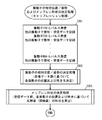
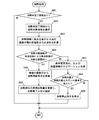
図5は、本実施形態における振動子の相対位置/姿勢およびメンブレン形状の決定処理(キャリブレーション処理)の流れを示すフローチャートである。本フローチャートに示された処理は、図4に示された起動・運転処理において、ステップS110が開始されたことを契機として実行される。即ち、本フローチャートは、図4に示された起動・運転処理のうち、ステップS110に示された処理をより詳細に説明するものである。
FIG. 5 is a flowchart showing the flow of the relative position / posture and membrane shape determination process (calibration process) of the vibrator in this embodiment. The processing shown in this flowchart is executed in response to the start of step S110 in the start-up / operation processing shown in FIG. That is, this flowchart explains in more detail the process shown in step S110 in the start-up / run process shown in FIG.
ステップS201では、超音波振動子12からのパルス発振、他の超音波振動子12による感知、および受信データの記録が行われる。制御部10は、超音波振動子アレイ13において超音波振動子12のうち所定数の超音波振動子12(発振側振動子)に対して、1つずつ順に駆動電圧の印加を行い、超音波を発振させる。発振された超音波は、発振に用いられていないその他の超音波振動子12によって、直接波および反射波として感知(受信)される。超音波を感知した超音波振動子12は感知信号を出力する。ここでは、あるタイムスロットにおいて発振を行う超音波振動子12が1つであるため、制御部10は、感知された超音波が当該タイムスロットにおいて発振を行っていた超音波振動子12から発振されたものであると把握することが出来る。なお、複数の超音波振動子12から同時に発振が行われた場合であっても、感知信号を受信した制御部10は、感知信号から、感知された超音波の振幅、周波数および位相等を得ることで、超音波振動子12毎の振幅、周波数、位相、到達時刻の時間差等の特徴に基づいて、感知された超音波が何れの超音波振動子12から発振されたものであるかを把握することが出来る。
In step S201, pulse oscillation from the ultrasonic transducer 12, sensing by another ultrasonic transducer 12, and recording of received data are performed. In the ultrasonic transducer array 13, the control unit 10 sequentially applies a driving voltage to a predetermined number of ultrasonic transducers 12 (oscillation-side transducers) among the ultrasonic transducers 12, thereby ultrasonic waves. Oscillates. The oscillated ultrasonic wave is sensed (received) as a direct wave and a reflected wave by other ultrasonic transducers 12 not used for oscillation. The ultrasonic transducer 12 that has detected the ultrasonic wave outputs a detection signal. Here, since there is one ultrasonic transducer 12 that oscillates in a certain time slot, the control unit 10 oscillates the detected ultrasonic wave from the ultrasonic transducer 12 that oscillated in the time slot. Can be grasped. Even when the oscillation is performed simultaneously from the plurality of ultrasonic transducers 12, the control unit 10 that has received the detection signal obtains the amplitude, frequency, phase, and the like of the detected ultrasonic wave from the detection signal. Thus, based on the characteristics such as the amplitude, frequency, phase, time difference of arrival time, etc. for each ultrasonic transducer 12, it is understood from which ultrasonic transducer 12 the detected ultrasonic wave is oscillated. I can do it.
制御部10は、発振に用いる超音波振動子12を変更しながら、所定数の超音波振動子12について発振および他の超音波振動子12による感知を行う。得られたデータは、発振された超音波振動子12、感知した超音波振動子12、発振時刻および感知時刻に関連付けて、制御部10のRAMまたはストレージに記録される。その後、処理はステップS202へ進む。
The control unit 10 oscillates and senses a predetermined number of ultrasonic transducers 12 with other ultrasonic transducers 12 while changing the ultrasonic transducers 12 used for oscillation. The obtained data is recorded in the RAM or storage of the control unit 10 in association with the oscillated ultrasonic transducer 12, the detected ultrasonic transducer 12, the oscillation time and the detection time. Thereafter, the process proceeds to step S202.
ステップS202では、各超音波振動子12の位置および向き(姿勢)が決定される。制御部10は、同一の超音波振動子12から発振されて感知された超音波について、受信データ群に基づいて、直接波が発振側振動子から感知側振動子に到達するまでにかかった時間(以下、「直接波伝搬時間」と称する)を算出し、また、反射波が発振側振動子から感知側振動子に到達するまでにかかった時間(以下、「反射波伝搬時間」と称する)を算出する。そして、制御部10は、複数の超音波振動子12の夫々について算出された直接波伝搬時間に基づいて、各超音波振動子12の位置および向き(姿勢)を算出する。その後、処理はステップS203へ進む。
In step S202, the position and orientation (attitude) of each ultrasonic transducer 12 are determined. The control unit 10 takes the time taken for the direct wave to reach the sensing-side transducer from the oscillation-side transducer based on the received data group for the ultrasonic waves detected by the same ultrasonic transducer 12 and sensed. (Hereinafter referred to as “direct wave propagation time”) and the time taken for the reflected wave to reach the sensing-side vibrator from the oscillation-side vibrator (hereinafter referred to as “reflected-wave propagation time”) Is calculated. Then, the control unit 10 calculates the position and orientation (attitude) of each ultrasonic transducer 12 based on the direct wave propagation time calculated for each of the plurality of ultrasonic transducers 12. Thereafter, the process proceeds to step S203.
ステップS203では、反射面(接触部112の接触面)の形状が決定される。制御部10は、同一の超音波振動子12から発振されて感知された超音波について、1回反射波が発振側振動子から感知側振動子に到達するまでにかかった時間(以下、「1回反射波伝搬時間」と称する)を算出する。そして、制御部10は、複数の超音波振動子12の夫々についてステップS202で算出された各超音波振動子12の位置及び向き(姿勢)、並びに反射波伝搬時間に基づいて、反射面(接触部112の接触面)の形状を算出する。その後、本フローチャートに示された処理は終了する。
In step S203, the shape of the reflective surface (contact surface of the contact portion 112) is determined. For the ultrasonic waves oscillated and sensed from the same ultrasonic vibrator 12, the control unit 10 takes the time taken for the reflected wave to reach the sensing vibrator from the oscillation vibrator (hereinafter referred to as "1"). (Referred to as “reflected wave propagation time”). Then, the control unit 10 determines the reflection surface (contact) based on the position and orientation (attitude) of each ultrasonic transducer 12 and the reflected wave propagation time calculated in step S202 for each of the plurality of ultrasonic transducers 12. The shape of the contact surface of the portion 112 is calculated. Thereafter, the processing shown in this flowchart ends.
次に、図6から図9を用いて、図5で説明したキャリブレーション処理のより詳細な処理内容を説明する。ここで、図6および図8のフローチャートでは、N個の超音波振動子12(transducer)を、それぞれTi(iは1からNの自然数)として示す。また、その他の記号の内容は以下の通りである。
Pi: Tiの座標
di: Tiの向き(姿勢)。超音波振動子12の発振面が向けられた方向を、大きさ1のベクトルとして表す。
τij: Tiから発振しTjで感知された波のうち、直接波伝搬時間
τ′ij: Tiから発振しTjで感知された波のうち、接触面Π上の反射点Rijで1回反射した波の伝搬時間(1回反射波伝搬時間)
bij: RijでのΠの法線
なお、ここで用いられる座標系は、適宜「特定のTiを原点に、特定のTjを(j≠i)をzx平面のx>0側に取る」等の規約を設けて固定される。
Next, more detailed processing contents of the calibration processing described in FIG. 5 will be described with reference to FIGS. Here, in the flowcharts of FIGS. 6 and 8, N ultrasonic transducers 12 (transducers) are indicated as T i (i is a natural number from 1 to N), respectively. The contents of other symbols are as follows.
P i: of T i coordinates d i: T i orientation of the (attitude). The direction in which the oscillation surface of the ultrasonic transducer 12 is directed is represented as a vector of size 1.
τ ij: T i of the wave sensed by the oscillation and T j from the direct wave propagation time τ 'ij: T i of the wave sensed by the oscillation and T j from the reflection point R ij on the contact surface Π Propagation time of a wave reflected once at a time (Propagation time of a reflected wave once)
b ij : normal line of Π at R ij Note that the coordinate system used here is “the specific T i is the origin, and the specific T j is (j ≠ i) on the x> 0 side of the zx plane. It is fixed with a rule such as “take”.
なお、図6から図9に示された処理で振動子の相対位置/姿勢およびメンブレン形状を算出(推定)する場合、予め以下の内容を前提とする。
1. メンブレン11上に配置された振動子の総数Nは既知
2. 超音波振動子はメンブレン11の凹部111上にお椀状に並んでいる
3. メンブレン11内に充填されているゲルの体積は既知
4. メンブレン11は均等に膨張する
5. メンブレン11が「収縮している」状態での超音波振動子12の配置は、超音波振動子12付きメンブレン11製造時に既知
これによって、N個の振動子の仮の位置(仮座標)を決めることが出来る。振動子の向きについては、全てある一点(焦点)を向いていると仮定しておく(仮方向)。具体的には、仮方向は、曲面を球面と近似したときの球面の中心Cに全ての振動子が向いていると仮定し、以下のように設定する。
When calculating (estimating) the relative position / posture of the transducer and the membrane shape by the processing shown in FIGS. 6 to 9, the following contents are preliminarily assumed.
1. The total number N of vibrators arranged on the membrane 11 is known2. 2. The ultrasonic transducers are arranged in a bowl shape on the concave portion 111 of the membrane 11. 3. The volume of the gel filled in the membrane 11 is known. 4. The membrane 11 expands evenly. The arrangement of the ultrasonic transducer 12 when the membrane 11 is “contracted” is known at the time of manufacturing the membrane 11 with the ultrasonic transducer 12, thereby determining the temporary positions (provisional coordinates) of the N transducers. I can do it. As for the direction of the vibrator, it is assumed that all are directed to a certain point (focal point) (provisional direction). Specifically, the provisional direction is set as follows assuming that all the transducers are directed to the center C of the spherical surface when the curved surface is approximated to a spherical surface.
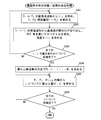
図6は、本実施形態における、振動子の相対位置/姿勢の決定処理の流れを示すフローチャートである。本フローチャートに示された処理は、図5に示されたキャリブレーション処理において、ステップS202が開始されたことを契機として実行される。即ち、本フローチャートは、図5に示されたキャリブレーション処理のうち、ステップS202に示された処理をより詳細に説明するものである。
FIG. 6 is a flowchart showing the flow of the relative position / posture determination process of the vibrator in the present embodiment. The process shown in this flowchart is executed in response to the start of step S202 in the calibration process shown in FIG. That is, this flowchart explains in more detail the process shown in step S202 in the calibration process shown in FIG.
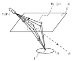
図7は、本実施形態において発振側振動子および感知側振動子の向き(姿勢)と、発振側振動子から発振されて感知側振動子において感知された直接波との関係を示す図である。図7に示した例では、発振側振動子Ti(座標Pi)から発振された超音波のうち、Tiの向きdiとθijの角をなす方向へ伝搬した超音波が、受信側振動子Tj(座標Pj)によって受信されている。
FIG. 7 is a diagram showing the relationship between the orientation (posture) of the oscillation-side vibrator and the sensing-side vibrator and the direct wave oscillated from the oscillation-side vibrator and sensed by the sensing-side vibrator in the present embodiment. . In the example shown in FIG. 7, of the ultrasonic wave oscillated from the oscillating side transducer T i (coordinate P i), the ultrasonic wave propagating in a direction forming an angle of orientation d i and theta ij of T i is received It is received by the side transducer T j (coordinates P j ).
ステップS301では、TiとTjとの間の距離が算出される。制御部10は、ステップS201で取得された、Tiから発振されてTjによって感知されたパルスの受信データのうち、直接波の波形からτijを特定する。なお、直接波は、仮座標Pi,Pjから算出された直接波の仮経路長(lij=|Pj-Pi|)と、メンブレン11内での音速c(本実施形態では、ゲル内での音波の伝搬速度)とに基づいて算出可能な、Tiから発振された超音波が直接Tjへ到達するまでの予想伝搬時間(τij,expected=lij/c)近傍でTjにて観測されたパルスを探すことで特定可能である。
In step S301, the distance between the T i and T j are calculated. The control unit 10 specifies τ ij from the waveform of the direct wave among the received data of the pulse oscillated from T i and sensed by T j acquired in step S201. Note that the direct wave includes the temporary path length (l ij = | P j −P i |) of the direct wave calculated from the temporary coordinates P i and P j and the sound velocity c in the membrane 11 (in this embodiment, can be calculated based on the wave propagation velocity in) in the gel, the expected propagation time until the ultrasonic waves oscillated from T i to reach directly T j (τ ij, with expected = l ij / c) near It can be specified by searching for a pulse observed at T j .
そして、制御部10は、算出されたτijと音速cとから、Ti-Tj間の距離|Pi-Pj|を算出する(距離は音速cと伝搬時間τijの積として、|Pi-Pj|=c*τijとなる)。その後、処理はステップS302へ進む。
Then, the control unit 10 calculates a distance | P i -P j | between T i and T j from the calculated τ ij and the sound speed c (the distance is a product of the sound speed c and the propagation time τ ij , | P i −P j | = c * τ ij ). Thereafter, the process proceeds to step S302.
ステップS302では、Tiが発振の中心軸およびTjを見込む角θijが算出される。先述の通り、「見込む角」とは、あるポイント(他の振動子や反射点等)が振動子の向きdiに伸びる発振の中心軸から何度ずれているかを示す角度であり、例えば、Tiが発振の中心軸およびTjを見込む角θijは、「Tiの発振面を通る中心軸の方向(Tiから発振された超音波が指向する中心方向)」と、「Tiの発振面の中心とTjの感知面の中心とを結ぶ線」と、がなす角度である(図7を参照)。
In step S302, T i is the angular theta ij expecting a central axis and T j of oscillation is calculated. As described above, the "expected corner" is an angle indicating whether a point (other oscillator and the reflection point, etc.) is shifted again from the central axis of oscillation extending in the direction d i vibrators, for example, T i is expected to central axis and T j of the oscillation angle theta ij is the "direction of the central axis through the oscillating surface of the T i (center direction ultrasonic wave oscillated from T i is directed)", "T i and a line connecting the center of the sensing surface and the center of the T j of the oscillation surface "is the angle formed by the (see Figure 7).
制御部10は、Tiから発振されてTjによって感知されたパルスの受信データのうち、受信波の波形から直接波の波形を切り出し、周波数領域表現(例えば、高速フーリエ変換やWavelet変換等)を用いてスペクトルを求め、Tiが発振の中心軸およびTjを見込む角θijを算出する。TiからTjへ送られた超音波パルス信号には、基本振動数以外に整数倍の高調波も含まれる。Fraunhofer領域では波長により指向性が異なることから、Tjで観測されたTiからの直接波パルスの高調波成分比は、Tiの向きdiと見込む角θijに依存する。このため、制御部10は、事前に計算或いは測定した成分比のθ依存性とTjで観測された高調波成分比とを比較することでθijを推定することができる。波が媒質を伝搬する際、媒質の粘性等に起因して振幅の減衰が起こるが、減衰率は波の振動数にも依存する。媒質が決まれば、減衰率の振動数依存性は既知であり、伝搬距離が分かれば媒質中を伝搬する間の減衰が振動数毎に計算し、媒質による減衰を補正することが出来る。その後、処理はステップS303へ進む。
Control unit 10, among the received data pulses sensed by oscillated by T j from T i, cutting out a direct wave of the waveform from the waveform of the received wave, the frequency domain representation (e.g., fast Fourier transform or Wavelet transform, etc.) A spectrum is obtained by using the above equation, and an angle θ ij in which T i looks at the central axis of oscillation and T j is calculated. The ultrasonic pulse signal sent from T i to T j includes an integral multiple of harmonics in addition to the fundamental frequency. From vary directivity by the wavelength at Fraunhofer region, the harmonic component ratio of the direct wave pulse from T i observed in T j depends on the angle theta ij expecting the direction d i of T i. For this reason, the control unit 10 can estimate θ ij by comparing the θ dependency of the component ratio calculated or measured in advance with the harmonic component ratio observed at T j . When the wave propagates through the medium, the amplitude is attenuated due to the viscosity of the medium. The attenuation factor also depends on the frequency of the wave. If the medium is determined, the frequency dependence of the attenuation rate is known. If the propagation distance is known, the attenuation during propagation through the medium is calculated for each frequency, and the attenuation due to the medium can be corrected. Thereafter, the process proceeds to step S303.
ステップS303では、制御部10によりTiからTjへ至る直接波の到達時間または周波数表現が判定可能なiおよびjの組み合わせ(iおよびjは1からNの自然数)のうち角度を算出可能な組み合わせについて、ステップS301およびステップS302の処理が終了したか否かが判定される。超音波振動子12間の距離算出および見込む角の算出が完了していない超音波振動子12の組み合わせがある場合、制御部10は、iおよびjを未完了の組み合わせに更新して、処理をステップS301へ戻す。一方、角度を算出可能な組み合わせについて超音波振動子12間の距離算出および見込む角の算出が完了したと判定された場合、処理はステップS304へ進む。
In step S303, the angle can be calculated from the combination of i and j (i and j are natural numbers from 1 to N) that can determine the arrival time or frequency expression of the direct wave from T i to T j by the control unit 10. For the combination, it is determined whether or not the processing of step S301 and step S302 has been completed. When there is a combination of the ultrasonic transducers 12 for which the calculation of the distance between the ultrasonic transducers 12 and the calculation of the expected angle are not complete, the control unit 10 updates i and j to an incomplete combination, and performs processing. Return to step S301. On the other hand, when it is determined that the calculation of the distance between the ultrasonic transducers 12 and the calculation of the expected angle are completed for the combination capable of calculating the angle, the process proceeds to step S304.
ステップS304では、各超音波振動子12の位置(Tiの座標Pi)が算出される。制御部10は、上記した仮座標および仮方向に基づいて算出される超音波振動子12間の距離および超音波振動子12が発振の中心軸および他の超音波振動子12を見込む角と、実際のパルス発振/感知によって得られたデータに基づいてステップS301からステップS303の処理で算出された超音波振動子12間の距離(|Pi-Pj|)および超音波振動子12が発振の中心軸および他の超音波振動子12を見込む角(θij)と、をパラメータとして、誤差を含むデータに対するフィッティングアルゴリズムを利用することで、Tiの座標Pi(iは1からNの自然数)を算出する。ここで用いられるフィッティングアルゴリズムは限定されず、例えば、最小二乗法(Lovenberg-Marquardt法など)や、kernel regression等を用いることが出来る。なお、これらのアルゴリズムによれば、算出された座標Pi(推定値)の誤差を見積もることも可能である。その後、処理はステップS305へ進む。
In step S304, the position of each of the ultrasonic transducers 12 (coordinates P i of T i) is calculated. The control unit 10 includes a distance between the ultrasonic transducers 12 calculated based on the temporary coordinates and the temporary direction, an angle at which the ultrasonic transducer 12 looks at the oscillation central axis and other ultrasonic transducers 12, Based on the data obtained by actual pulse oscillation / sensing, the distance (| P i −P j |) between the ultrasonic transducers 12 calculated by the processing from step S301 to step S303 and the ultrasonic transducer 12 oscillate. the central axis and the angle (theta ij) looking into other ultrasonic transducer 12, as a parameter, by using a fitting algorithm for data including an error, T i coordinates P i of (i from 1 to N Natural number) is calculated. The fitting algorithm used here is not limited, and for example, a least square method (Lovenberg-Marquardt method or the like), kernel regression, or the like can be used. In addition, according to these algorithms, it is also possible to estimate the error of the calculated coordinates P i (estimated value). Thereafter, the process proceeds to step S305.
ステップS305では、超音波振動子Tiの向き(姿勢)diが算出される。制御部10は、Pi,Pj,θijの組から、jについて2組以上選び、diを求める。ここまでの処理で、Tiからみて遠方(Fraunhofer領域)にある、Tjとは異なる超音波振動子Tk,Tl,・・・についてもθk,θl,・・・が算出されている。このため、Tiの向きdiとi→j,i→k,i→l,・・・のなす角θj,θk,θl,・・・が分かる。このとき、cosθjが以下の式によって求められるため、2組以上の独立な条件(例えば、i,jの組とi,kの組)が与えられれば、振動子の向きdi(自由度は2)を決定することが出来る。その後、処理はステップS306へ進む。
In step S305, the orientation of the ultrasonic transducer T i (attitude) d i are calculated. The control unit 10 selects two or more sets of j from the set of P i , P j , and θ ij to obtain d i . Up to this point, θ k , θ l ,... Are calculated for ultrasonic transducers Tk, Tl,... Different from T j far from the T i (Fraunhofer region). . Therefore, the angles θ j , θ k , θ l ,... Formed by the direction d i of T i and i → j, i → k, i → l,. At this time, since cos θ j is obtained by the following expression, if two or more sets of independent conditions (for example, a set of i, j and a set of i, k) are given, the orientation d i of the vibrator (degree of freedom) 2) can be determined. Thereafter, the process proceeds to step S306.
ステップS306では、向きdiを算出可能なi(1からNの自然数)の夫々について、ステップS305の処理が終了したか否かが判定される。振動子の向きdiの算出が完了していない超音波振動子12がある場合、制御部10は、iを未完了の超音波振動子12番号に更新して、処理をステップS305へ戻す。一方、超音波振動子12のうち算出可能なものについて向きdiの算出が完了したと判定された場合、本フローチャートに示された処理は終了する。
In step S306, it is determined whether or not the processing in step S305 is completed for each i (natural number from 1 to N) for which the direction d i can be calculated. If there is an ultrasonic transducer 12 for which the calculation of the transducer orientation d i has not been completed, the control unit 10 updates i to the ultrasonic transducer 12 number that has not been completed, and returns the processing to step S305. On the other hand, when it is determined that the calculation of the orientation d i has been completed for the ultrasonic transducers 12 that can be calculated, the processing illustrated in this flowchart ends.
上記説明した振動子の相対位置/姿勢の決定処理によれば、位置と向きを算出可能なTiについて、位置と向き{Pi,di}(iは1からNの自然数)が算出される。その後、引き続きメンブレン形状の決定処理が実行される。
According to the determination processing of the relative position / orientation of the transducers described above, the T i can be calculated the position and orientation, position and orientation {P i, d i} (a natural number of i is from 1 N) is calculated The Thereafter, the membrane shape determination process is subsequently executed.
図8は、本実施形態における、メンブレン形状の決定処理の流れを示すフローチャートである。本フローチャートに示された処理は、図5に示されたキャリブレーション処理において、ステップS203が開始されたことを契機として実行される。即ち、本フローチャートは、図5に示されたキャリブレーション処理のうち、ステップS203に示された処理をより詳細に説明するものである。このため、本フローチャーに示された処理が実行される前に、Tiのうち算出可能なものについて、位置と向き{Pi,di}(iは1からNの自然数)は算出済である。
FIG. 8 is a flowchart showing the flow of the membrane shape determination process in the present embodiment. The processing shown in this flowchart is executed in response to the start of step S203 in the calibration processing shown in FIG. That is, this flowchart explains in more detail the process shown in step S203 in the calibration process shown in FIG. For this reason, the position and orientation {P i , d i } (i is a natural number from 1 to N) have been calculated for those that can be calculated among T i before the processing shown in this flowchart is executed. It is.
図9は、本実施形態において発振側振動子および感知側振動子の向き(姿勢)と、発振側振動子から発振されて感知側振動子において感知された反射波との関係を示す図である。図9に示した例では、発振側振動子Ti(座標Pi)から発振された超音波は、Tiの向きdiとφi→Rijの角をなす方向へ伝搬し、反射点Rijにおける反射を経て、受信側振動子Tj(座標Pj)の向きdjとθRij→jの角をなす方向から受信側振動子Tjに入射し、受信側振動子Tjに受信される。
FIG. 9 is a diagram illustrating the relationship between the orientation (posture) of the oscillation-side vibrator and the sensing-side vibrator and the reflected wave oscillated from the oscillation-side vibrator and sensed by the sensing-side vibrator in the present embodiment. . In the example shown in FIG. 9, the ultrasonic wave oscillated from the oscillation-side vibrator T i (coordinate P i ) propagates in a direction that forms an angle of φ i → Rij with the direction d i of T i , and the reflection point R After reflection at ij, the light enters the receiving-side transducer T j from the direction that forms an angle of θ Rij → j with the direction d j of the receiving-side transducer T j (coordinate P j ), and is received by the receiving-side transducer T j Is done.
ステップS401では、TiからTjへの1回反射波の経路の長さが算出される。制御部10は、ステップS201で取得された、Tiから発振されてTjによって感知されたパルスの受信データのうち、1回反射波の波形からτ′ijを特定する。ここでは、振動子Tiから発振された超音波パルス信号が接触面Π上の点Rijで反射し、振動子Tjで観測された場合について、1回反射波の経路の長さを算出する(図9を参照)。Tiから発振されたパルスは、Tjで観測される際にはTi→Rij→Tjの経路長に依存した減衰に加えて、発振側の指向性、反射率、および感知側の指向性の影響を受けて、媒質中を伝搬し感知側の振動子に到達する間に減衰および波形の変形が起きる。なお、ここで、発振側の指向性はスペクトルに影響を与え、感知側の指向性は感知されたパルスの強度(感度)に影響を与える(スペクトルへの影響は無いかまたは無視出来る)。また、反射率は、媒質と接触部112(接触面)の音響インピーダンスから決まる。
In step S401, the length of a single reflected wave path from T i to T j is calculated. The control unit 10 specifies τ ′ ij from the waveform of the reflected wave once from the received data of the pulse oscillated from T i and sensed by T j acquired in step S201. Here, when the ultrasonic pulse signal oscillated from the transducer T i is reflected at the point R ij on the contact surface 、 and observed by the transducer T j , the path length of the reflected wave is calculated once. (See FIG. 9). When the pulse oscillated from T i is observed at T j , in addition to attenuation depending on the path length of T i → R ij → T j , the directivity on the oscillation side, the reflectance, and the sensing side Under the influence of directivity, attenuation and waveform deformation occur while propagating through the medium and reaching the sensing-side vibrator. Here, the directivity on the oscillation side affects the spectrum, and the directivity on the sensing side affects the intensity (sensitivity) of the detected pulse (the spectrum has no influence or can be ignored). The reflectance is determined from the acoustic impedance of the medium and the contact portion 112 (contact surface).
そして、Tiから発振された超音波パルス信号(時刻t0に発振)がTjで観測された時、Tjで感知されたパルス信号は、到達時刻の早い方から順に、以下のものが観測されるはずである。
(1)Ti→Tjの直接波
(2)Ti→Rij→Tjの1回反射波
(3)メンブレン11内の多重反射波、体内で反射した反射波
このため、一般的には、Tjによって感知された波形のうち、直接波を除いて最も強い反射波が、1回反射波であると推定される。但し、実際には、凹部111の曲率とi,jの組み合わせによっては直接波または1回反射波が弱すぎて見えないか、重なって分離出来ない場合もあり得る。このようなケースについては、事前に実験・試運転した際に直接波または1回反射波の伝搬時間や強度、分離可能性について調べたものを参考にしてもよい。直接波については、Ti-Tj間の直接波の予想伝搬時間に近い時間で感知された波形の有無を確認することで、直接波の有無を判定することができる(ステップS301を参照)。
When the ultrasonic pulse signal oscillated from T i (oscillation time t0) was observed at T j, the pulse signal detected by the T j, in order from whichever arrival time, is observed the following Should be done.
(1) Direct wave of T i → T j (2) Single reflected wave of T i → R ij → T j (3) Multiple reflected waves in the membrane 11 and reflected waves reflected in the body Is estimated that the strongest reflected wave except the direct wave among the waveforms sensed by T j is a reflected wave once. However, in practice, depending on the combination of the curvature of the concave portion 111 and i and j, the direct wave or the reflected wave once is too weak to be seen or overlapped and cannot be separated. For such a case, it is possible to refer to a case in which the propagation time, intensity, and separability of a direct wave or a single reflected wave are examined in advance during an experiment / trial operation. The direct wave, by checking the presence or absence of the sensed waveform with time of the direct component estimated propagation time between T i -T j, it is possible to determine the presence of a direct wave (see step S301) .
そして、制御部10は、特定された1回反射波のピークに基づいてτ′ijを求め、τ′ijと音速cとから、TiからTjへの1回反射波の経路(Ti→Rij→Tj)の長さを算出する。算出方法は、直接波の経路の長さを算出したステップS301の処理と同様である。その後、処理はステップS402へ進む。
Then, the control unit 10 obtains τ ′ ij based on the identified peak of the single reflected wave, and the path (T i) of the single reflected wave from T i to T j from τ ′ ij and the sound velocity c. → R ij → T j ) is calculated. The calculation method is the same as that in step S301 in which the length of the direct wave path is calculated. Thereafter, the process proceeds to step S402.
ステップS402では、Tiが発振の中心軸および反射点Rijを見込む角φi→Rijが算出される。制御部10は、Tiから発振されてTjによって感知されたパルスの受信データのうち、受信波の波形から1回反射波の波形を切り出し、周波数領域表現(例えば、高速フーリエ変換やWavelet変換等)を用いてスペクトルを求め、Tiが発振の中心軸および反射点Rijを見込む角φi→Rijを算出する。算出方法は、ステップS302の処理と同様である。その後、処理はステップS403へ進む。
In step S402, an angle φ i → Rij where T i takes into account the central axis of oscillation and the reflection point R ij is calculated. The control unit 10 cuts out the waveform of the reflected wave once from the waveform of the received wave from the received data of the pulse oscillated from T i and sensed by T j , and expresses the frequency domain representation (for example, fast Fourier transform or wavelet transform). Etc.) to obtain a spectrum, and calculate an angle φ i → Rij where T i expects a central axis of oscillation and a reflection point R ij . The calculation method is the same as that in step S302. Thereafter, the process proceeds to step S403.
ステップS403では、1回反射波のTjへの入射角θRij→jが算出される。制御部10は、Tiから発振されてTjによって感知されたパルスの受信データのうち、感知パルスの強度及び接触面での反射率に基づいて、Tjへの入射角θRij→jを算出する。同じ強度のパルスが感知側振動子に到達した場合、入射角が感知側振動子の感知面に対して垂直である場合に感知される信号の強度は高く、入射角が垂直から離れるほど強度は弱くなる。このため、制御部10は、感知側振動子がパルスを垂直に感知した場合の推定強度と、実際に受信された感知信号の強度とを比較し、その差に基づいて、入射角を算出する。推定強度は、発振側振動子からの発射角度、振動数、媒質の減衰率および伝搬距離等に基づいて算出される推定強度を、接触面における反射率を用いて補正することで算出可能である。その後、処理はステップS404へ進む。
In step S403, the incident angle theta Rij → j to T j of one reflected wave is calculated. Control unit 10, among the received data pulses sensed by oscillated by T j from T i, based on the reflectance intensity of the sensing pulse and the contact surface, the incident angle theta Rij → j to T j calculate. When a pulse with the same intensity reaches the sensing transducer, the intensity of the detected signal is high when the incident angle is perpendicular to the sensing surface of the sensing transducer, and the intensity increases as the incident angle goes away from the vertical. become weak. For this reason, the control unit 10 compares the estimated intensity when the sensing-side transducer senses the pulse vertically with the intensity of the actually received sensing signal, and calculates the incident angle based on the difference. . The estimated intensity can be calculated by correcting the estimated intensity calculated based on the emission angle from the oscillation-side vibrator, the frequency, the attenuation factor of the medium, the propagation distance, and the like using the reflectance at the contact surface. . Thereafter, the process proceeds to step S404.
ステップS404では、iおよびjの組み合わせ(iおよびjは1からNの自然数)のうちφi→RijとθRij→jの組が算出可能なものについて、ステップS401からステップS403の処理が終了したか否かが判定される。算出が完了していない超音波振動子12の組み合わせがある場合、制御部10は、iおよびjを未完了の組み合わせに更新して、処理をステップS401へ戻す。算出可能な組み合わせ全てについて算出が完了したと判定された場合、処理はステップS405へ進む。
In step S404, the i and j combination (i and j from 1 natural number N) capable calculated set of phi i → Rij and theta Rij → j of the process of step S403 is finished from step S401 It is determined whether or not. If there is a combination of the ultrasonic transducers 12 that has not been calculated, the control unit 10 updates i and j to an uncompleted combination, and returns the process to step S401. If it is determined that the calculation has been completed for all the combinations that can be calculated, the process proceeds to step S405.
ステップS405では、反射点Rijの座標が算出される。制御部10は、ステップS404までの処理で得られた、{Pi,di}、{Pj,dj}、経路(Ti→Rij→Tj)長、経路の見込み角{φi→Rij,θRij→j}のデータに基づいて、Rijを算出する。具体的には、以下の式を用いて算出することが出来る。
In step S405, the coordinates of the reflection point Rij are calculated. Control unit 10 was obtained by the processing up to step S404, {P i, d i }, {P j, d j}, the path (T i → R ij → T j) length, angle of view of the path {phi R ij is calculated based on the data of i → Rij and θ Rij → j }. Specifically, it can be calculated using the following equation.
なお、Rijの算出に用いられる、観測値・観測値から推定される値は、何れも誤差を含むため、最小二乗法等のフィッティングアルゴリズムを用いてRijの位置を決め、誤差を評価してもよい。また、Ti,Rij,Tjの3点の位置が得られているため、Ti,Rij,Tjの3点が乗る平面上で、角TiRijTjを2等分するベクトルを得ることが出来る。このベクトルは、反射点Rij近傍の曲面を特徴付ける「接平面」の法線bijに相当するため、ここでは、反射点での接平面も得られる。i,jを変えて上記の処理が繰り返されることで、最大(1/2)N(N-1)個の反射点の座標、および反射点での接平面が得られる。その後、処理はステップS406へ進む。
Incidentally, used for calculating the R ij, the value estimated from the observed values and observation values, both to contain the error, to position the R ij using fitting algorithm such as the least squares method, to evaluate the error May be. Since the positions of three points T i , R ij , and T j are obtained, the angle T i R ij T j is divided into two equal parts on the plane on which the three points T i , R ij , and T j are placed. Can be obtained. Since this vector corresponds to the normal line b ij of the “tangent plane” characterizing the curved surface near the reflection point R ij , the tangent plane at the reflection point is also obtained here. By repeating the above process while changing i and j, the coordinates of the maximum (½) N (N−1) reflection points and the tangent plane at the reflection points are obtained. Thereafter, the process proceeds to step S406.
ステップS406では、接触面Πの形状が算出される。上述の通り、ここまでの処理によって、最大(1/2)N(N-1)個の反射点の座標および接平面が得られている。このため、制御部10は、これらの情報に基づいて、反射点近傍の曲面形状を多項式補間やスプライン補間等を用いて求め、接触面Πの形状を得る。具体的には、制御部10は、例えば、以下の手順を用いて接触面Πの形状を得る。
(1)反射点Rを一つ選ぶ
(2)R近傍の反射点を、Rからの距離が小さい順に複数選ぶ
(3)R近傍で曲面は(x,y,z)の2-3次の多項式、スプライン関数等で近似できると仮定し、Rとその近傍点を通り、その点付近では、接平面上に乗るという条件を課すと、R近傍の曲面を再現する関数が決まる。
In step S406, the shape of the contact surface flaw is calculated. As described above, the coordinates and tangent planes of the maximum (1/2) N (N−1) reflection points are obtained by the processing so far. Therefore, the control unit 10 obtains the shape of the curved surface near the reflection point using polynomial interpolation, spline interpolation, or the like based on such information, and obtains the shape of the contact surface defect. Specifically, the control unit 10 obtains the shape of the contact surface defect using, for example, the following procedure.
(1) Select one reflection point R (2) Select a plurality of reflection points in the vicinity of R in ascending order of the distance from R (3) The curved surface in the vicinity of R is a 2-3 order of (x, y, z) Assuming that it can be approximated by a polynomial, a spline function or the like, and passing through R and its neighboring points, and placing on the tangent plane near that point, a function for reproducing the curved surface in the vicinity of R is determined.
なお、法線の情報を使わず、多くの点を使って補間関数を決めてもよいし、反射点の誤差情報から、補間関数の誤差を見積もってもよい。その後、本フローチャートに示された処理は終了する。
Note that the interpolation function may be determined using many points without using the normal information, or the error of the interpolation function may be estimated from the error information of the reflection point. Thereafter, the processing shown in this flowchart ends.
図10は、本実施形態における、スキャン・画像化処理の流れを示すフローチャートである。本フローチャートに示された処理は、図4に示された起動・運転処理において、ステップS111が開始されたことを契機として実行される。即ち、本フローチャートは、図4に示された起動・運転処理のうち、ステップS111に示された処理をより詳細に説明するものである。
FIG. 10 is a flowchart showing the flow of scanning / imaging processing in the present embodiment. The processing shown in this flowchart is executed in response to the start of step S111 in the start-up / operation processing shown in FIG. That is, this flowchart explains in more detail the process shown in step S111 among the start-up and operation processes shown in FIG.
ステップS501では、画像化のために発振する超音波ビームの焦点が決定される。制御部10は、画像化したい領域に基づいて画像化の為の超音波ビーム収束方向を決定し、決定された方向にビームが収束するように焦点の位置(座標)を決定する。その後、処理はステップS502へ進む。
In step S501, the focal point of the ultrasonic beam oscillated for imaging is determined. The control unit 10 determines an ultrasonic beam convergence direction for imaging based on a region to be imaged, and determines a focus position (coordinates) so that the beam converges in the determined direction. Thereafter, the process proceeds to step S502.
ステップS502では、位相制御による焦点合わせのための計算が行われる。各振動子から伝搬した波を特定の一点で位相を合わせ、強め合うように制御するには、各振動子から伝搬する波が、ターゲット(焦点)を通過する時に振幅が大きくなる(特定の位相の)状態となるように、各振動子からターゲットに到達するまでの伝搬時間を見積もる。
In step S502, calculation for focusing by phase control is performed. To control the waves propagating from each transducer so that the phases are matched and strengthened at a specific point, the amplitude of the waves propagating from each transducer increases when passing through the target (focus) (specific phase (Ii) Estimate the propagation time from each transducer to the target.
図11は、本実施形態において位相制御による焦点合わせを行うための計算内容を示す模式図である。ここで、既に得られている接触面上の点(反射点や反射点間を補間した点)の集合を{Rj:j=1,・・・m}とする。また、Ti→Rjの経路は通常の指向性を有する伝搬とし、Rj→FはRjを波源とする球面波とする。そして、制御部10は、Ti→Rj→F(iは1からnの自然数。jは1からmの自然数)という経路の経路長lTi→Rj→Fと指向性因子P(θij)から導かれるTi→Rj→Fという経路で伝搬した波を、全ての経路Rj(jは1からmの自然数)について足しあげることで、Tiから発振し、接触面を通過してターゲットFを通過する波の波形(振幅・位相・伝搬時間)を求める(図11を参照)。このようにして、制御部10は、発振に用いられる超音波振動子12について、ターゲットFを通過する波の波形(振幅・位相・伝搬時間)を求める。
FIG. 11 is a schematic diagram showing the calculation content for performing focusing by phase control in the present embodiment. Here, the set of points on the contact surface already obtained (points interpolated between the reflection point and the reflection point) {R j: j = 1 , ··· m} and. The path of T i → R j is assumed to be propagation having normal directivity, and R j → F is assumed to be a spherical wave having R j as a wave source. Then, the control unit 10 determines the path length lT i → R j → F of the path T i → R j → F (i is a natural number from 1 to n, j is a natural number from 1 to m) and the directivity factor P (θ waves propagated in T i → R j → F that pathway derived from ij), all paths R j (j is that i'll adding from 1 natural number m) for, oscillated from T i, passes through the contact surface Thus, the waveform (amplitude, phase, propagation time) of the wave passing through the target F is obtained (see FIG. 11). In this way, the control unit 10 obtains the waveform (amplitude / phase / propagation time) of the wave passing through the target F for the ultrasonic transducer 12 used for oscillation.
その後、制御部10は、複数の発振側振動子から発振される波の振幅がターゲットFで最も大きくなるように、複数の発振側振動子間で、発振時刻(位相)を調整する。具体的には、制御部10は、Tiから鋭いパルスを発した場合に、発振してからFを通過する波の振幅が最大になるまでの時間をτiとし、τiが最大になる発振側振動子に対して他の振動子の発振時刻(位相)を遅らせ、Fで振幅が最大となるタイミングが一致するように設定する。このようにすることで、ターゲットFを通過する複数の振動子からの波は最も振幅が大きくなる通過時刻が一致し、ターゲットが焦点となる。
Thereafter, the control unit 10 adjusts the oscillation time (phase) among the plurality of oscillation-side vibrators so that the amplitude of the wave oscillated from the plurality of oscillation-side vibrators becomes the largest at the target F. Specifically, when a sharp pulse is emitted from T i , the control unit 10 sets τ i as the time from the oscillation until the amplitude of the wave passing through F becomes maximum, and τ i becomes maximum. The oscillation time (phase) of other oscillators is delayed with respect to the oscillation-side oscillator, and the timing at which the amplitude becomes maximum at F is set to coincide. By doing in this way, the waves from the plurality of vibrators passing through the target F coincide with each other at the passing time when the amplitude becomes the largest, and the target becomes the focus.
なお、本実施形態では、媒質が変わる面が1面(媒質がゲルと生体8の2層)である場合について説明したが(図11を参照)、媒質が変わる面が2面以上である場合であっても、媒質が変わる面の形状を得ることが出来れば、同様の処理によって、位相制御による焦点合わせを行うことが出来る。また、この際上述した接触面の形状決定法を用いて2面目以降の面の形状を推定することも可能である。即ち、本開示によれば、多層構造で複雑に屈折を繰り返すような対象であっても、焦点制御を行うことが可能である。その後、処理はステップS503へ進む。
In the present embodiment, the case where the surface where the medium changes is one surface (the medium is the two layers of the gel and the living body 8) has been described (see FIG. 11), but there are two or more surfaces where the medium changes. Even so, if the shape of the surface on which the medium changes can be obtained, focusing by phase control can be performed by the same processing. At this time, it is also possible to estimate the shapes of the second and subsequent surfaces using the contact surface shape determination method described above. That is, according to the present disclosure, it is possible to perform focus control even for an object that has a multilayer structure and repeatedly refracts. Thereafter, the process proceeds to step S503.
ステップS503では、スキャン用パルスの発振が行われる。制御部10は、ステップS502で設定された通りに位相制御を行い、各超音波振動子12からスキャン用パルスを発振させる。また、発振されたパルスの反射波は、各超音波振動子12によって感知される。超音波を感知した超音波振動子12は感知信号を出力し、感知信号を受信した制御部10は、感知信号から、感知された超音波の振幅、周波数および位相等を得る。得られたデータは制御部10のRAMまたはストレージに記録される。その後、処理はステップS504へ進む。
In step S503, the scan pulse is oscillated. The control unit 10 performs phase control as set in step S <b> 502 and oscillates a scanning pulse from each ultrasonic transducer 12. The reflected wave of the oscillated pulse is detected by each ultrasonic transducer 12. The ultrasonic transducer 12 that has detected the ultrasonic wave outputs a detection signal, and the control unit 10 that has received the detection signal obtains the amplitude, frequency, phase, and the like of the detected ultrasonic wave from the detection signal. The obtained data is recorded in the RAM or storage of the control unit 10. Thereafter, the process proceeds to step S504.
ステップS504では、画像化に必要な構造データが揃ったか否かが判定される。画像化の対象となっている領域のうち未スキャンの領域がある場合、処理はステップS501へ戻る。一方、画像化の対象となっている範囲のスキャンが全て完了し、必要なデータが得られた場合、処理はステップ505へ進む。
In step S504, it is determined whether or not the structural data necessary for imaging has been prepared. If there is an unscanned area among the areas to be imaged, the process returns to step S501. On the other hand, when all the scans in the range to be imaged are completed and necessary data is obtained, the process proceeds to step 505.
ステップS505では、画像処理が行われる。制御部10は、反射波を感知した超音波振動子12から出力された感知信号を増幅およびデジタル化処理し、反射波に基づいて加熱対象9を含む生体8内の三次元画像データおよび断面画像を生成する。反射波を用いた三次元画像データの生成には、エコー検査等に用いられている従来技術を採用することが出来る。また、制御部10は、現在のメンブレン11の曲率、加熱用超音波の位相の設定等から、加熱位置(焦点位置)の座標が、三次元画像データ中の何れの位置であるかを特定する。更に、制御部10は、生成された断面画像や特定されたターゲットのデータに基づいて、表示装置18の表示内容を更新する。
In step S505, image processing is performed. The control unit 10 amplifies and digitizes the sensing signal output from the ultrasonic transducer 12 that senses the reflected wave, and based on the reflected wave, the three-dimensional image data and the cross-sectional image in the living body 8 including the heating target 9. Is generated. Conventional technology used for echo inspection or the like can be employed for generating three-dimensional image data using reflected waves. Further, the control unit 10 specifies which position in the three-dimensional image data the coordinates of the heating position (focal position) are based on the current curvature of the membrane 11, the setting of the phase of the ultrasonic wave for heating, and the like. . Furthermore, the control unit 10 updates the display content of the display device 18 based on the generated cross-sectional image and the specified target data.
この際、血流情報や画像診断によるターゲット捕捉(加熱対象9の特定)および表示が行われてもよい。血流情報や画像診断によるターゲット捕捉についても、エコー検査等に用いられている従来技術を採用することが出来る。制御部10は、画像中から加熱対象9を特定し、画像中における加熱対象9の位置情報を画像データと合わせて記憶する。
At this time, target capture (specification of the heating object 9) and display may be performed by blood flow information or image diagnosis. Conventional techniques used for echo inspection and the like can also be adopted for target acquisition by blood flow information and image diagnosis. The control unit 10 specifies the heating object 9 from the image, and stores the positional information of the heating object 9 in the image together with the image data.
また、制御部10は、得られた三次元画像データに基づいて二次元画像データを生成し、更に当該二次元画像データ上における加熱対象9の位置および加熱位置(焦点位置)を特定する。二次元画像データ上における加熱位置は、三次元画像データ中の加熱位置を、二次元画像データに投影することで特定することが出来る。そして、制御部10は、生成された二次元画像データを、当該二次元画像データ中における加熱対象9の位置および焦点位置を示す表示と共に出力し、表示装置18に表示させる。その後、本フローチャートに示された処理は終了する。
Further, the control unit 10 generates two-dimensional image data based on the obtained three-dimensional image data, and further specifies the position of the heating object 9 and the heating position (focal position) on the two-dimensional image data. The heating position on the two-dimensional image data can be specified by projecting the heating position in the three-dimensional image data onto the two-dimensional image data. And the control part 10 outputs the produced | generated two-dimensional image data with the display which shows the position and focus position of the heating target 9 in the said two-dimensional image data, and displays on the display apparatus 18. FIG. Thereafter, the processing shown in this flowchart ends.
ここで、二次元画像データ中における加熱対象9の特定は、本フローチャートに示された処理が開始されてから1回目にステップS505が実行された際には、ユーザーの入力に基づいて行われ、2回目以降にステップS505が実行された際には、以前にステップS505が実行された際の画像データと今回ステップS505が実行された際の画像データとの比較処理(マッチング処理)によって行われてもよい。
Here, the identification of the heating object 9 in the two-dimensional image data is performed based on the input of the user when step S505 is executed for the first time after the processing shown in this flowchart is started, When step S505 is executed after the second time, it is performed by a comparison process (matching process) between the image data when step S505 has been executed previously and the image data when step S505 is executed this time. Also good.
より具体的には、1回目にステップS505が実行された際には、制御部10は、二次元画像データを表示装置18に表示させ、表示された画像を確認したユーザーによる指定操作を受け付けることで、画像データにおける加熱対象9の位置を特定する。ここで、ユーザーによる指定操作とは、例えば、表示装置18がタッチパネル式ディスプレイである場合には、ディスプレイ上の加熱対象9が表示されている位置をユーザーがタッチする操作である。制御部10は、ユーザーによって指定された、画像データ上の加熱対象9の位置および画像上の特徴を記憶する。但し、本実施形態では、ユーザー指定に基づいて加熱対象9が特定される仕様を採用した例について説明したが、加熱対象9の特定には、その他の技術が採用されてもよい。例えば、画像データ中の各画素の輝度や色調等に基づいて、加熱対象9が制御部10によって自動的に特定される仕様が採用されてもよい。
More specifically, when step S505 is executed for the first time, the control unit 10 displays two-dimensional image data on the display device 18 and accepts a designation operation by the user who confirmed the displayed image. Thus, the position of the heating object 9 in the image data is specified. Here, the designation operation by the user is, for example, an operation in which the user touches the position where the heating target 9 is displayed on the display when the display device 18 is a touch panel display. The control unit 10 stores the position of the heating object 9 on the image data and the feature on the image specified by the user. However, in the present embodiment, an example has been described in which the specification in which the heating target 9 is specified based on the user designation has been described. However, other techniques may be used to specify the heating target 9. For example, a specification in which the heating target 9 is automatically specified by the control unit 10 based on the luminance and color tone of each pixel in the image data may be employed.
2回目以降にステップS505が実行された際には、制御部10は、撮像によって新たに生成された画像データと、以前の画像データとを比較(マッチング)することで、新たに生成された画像データ中の何れの箇所が、以前の画像データにおいて特定された加熱対象9に対応する箇所であるのかを判断し、新たに生成された画像データ中において、以前の画像データにおいて特定された加熱対象9に対応する箇所であると判断された箇所を、加熱対象9として特定する。
When step S505 is executed after the second time, the control unit 10 compares (matches) the image data newly generated by imaging with the previous image data to newly generate the image. It is determined which part in the data corresponds to the heating object 9 specified in the previous image data, and in the newly generated image data, the heating object specified in the previous image data A location determined to be a location corresponding to 9 is identified as the heating target 9.
図12は、本実施形態における、加熱処理の流れを示すフローチャートである。本フローチャートに示された処理は、図4に示された起動・運転処理において、ステップS113が開始されたことを契機として実行される。即ち、本フローチャートは、図4に示された起動・運転処理のうち、ステップS113に示された処理をより詳細に説明するものである。
FIG. 12 is a flowchart showing the flow of heat treatment in the present embodiment. The processing shown in this flowchart is executed in response to the start of step S113 in the start-up / operation processing shown in FIG. That is, this flowchart explains in more detail the process shown in step S113 among the start-up and operation processes shown in FIG.
ステップS601およびステップS602では、加熱未完了の領域がある場合に、加熱対象領域が選択される。制御部10は、保持している画像データにおける加熱対象9全体の領域と、これまでの処理において蓄積された加熱完了領域とを比較することで、加熱対象9において加熱が完了していない領域が有るか否かを判定する(ステップS601)。
In step S601 and step S602, when there is an unfinished region for heating, a heating target region is selected. The control unit 10 compares the area of the entire heating object 9 in the stored image data with the heating completion area accumulated in the processing so far, so that an area in the heating object 9 where heating has not been completed is obtained. It is determined whether or not there is (step S601).
加熱未完了の領域が残っていない(加熱対象9の全体が加熱完了である)と判定された場合、本フローチャートに示された処理は終了する。一方、加熱未完了の領域が残っていると判定された場合、制御部10は、加熱未完了の領域から、次の加熱の対象となる加熱対象領域を選択する(ステップS602)。ここで、制御部10は、例えば、加熱対象9の領域内で加熱位置(焦点位置)が移動するように、加熱対象領域を選択する。その後、処理はステップS603へ進む。
When it is determined that there is no unheated area remaining (the heating target 9 is entirely heated), the processing shown in this flowchart ends. On the other hand, when it is determined that the unheated region remains, the control unit 10 selects a heating target region to be the next heating target from the unheated region (step S602). Here, for example, the control unit 10 selects the heating target region so that the heating position (focus position) moves within the region of the heating target 9. Thereafter, the process proceeds to step S603.
ステップS603では、加熱領域に焦点を合わせる為の超音波振動子12同士の位相差または波形が計算され、位相制御または位相共役法等を用いた焦点制御が行われる。処理の詳細は図10を用いて説明したステップS502と同様であるため、省略する。その後、処理はステップS604へ進む。
In step S603, the phase difference or waveform between the ultrasonic transducers 12 for focusing on the heating region is calculated, and focus control using phase control or phase conjugation is performed. The details of the process are the same as step S502 described with reference to FIG. Thereafter, the process proceeds to step S604.
ステップS604では、加熱対象領域が位相制御による焦点制御可能な範囲内であるか否かが判定される。制御部10は、加熱位置(焦点位置)を、ステップS603で計算された焦点制御によって加熱対象9の位置に合わせられるか否かを判定する。加熱対象領域が焦点制御可能な範囲内でない場合、換言すれば、加熱位置と加熱対象9とのズレが、超音波振動子12から発振される超音波の焦点制御によって解消可能な範囲の上限よりも大きいと判定された場合、処理はステップS607へ進む。一方、加熱対象領域が焦点制御可能な範囲内である場合、処理はステップS605へ進む。
In step S604, it is determined whether or not the heating target region is within a range in which focus control by phase control is possible. The control unit 10 determines whether or not the heating position (focus position) can be adjusted to the position of the heating target 9 by the focus control calculated in step S603. If the heating target region is not within the focus controllable range, in other words, the deviation between the heating position and the heating target 9 is higher than the upper limit of the range that can be eliminated by the focus control of the ultrasonic wave oscillated from the ultrasonic transducer 12. If it is determined that the value is also larger, the process proceeds to step S607. On the other hand, when the heating target area is within the range where focus control is possible, the process proceeds to step S605.
ステップS605では、加熱用超音波の発振が行われる。加熱指示の入力を受けた制御部10は、ステップS602からステップS604までの処理で設定された通りに焦点制御を行い、各超音波振動子12に加熱用の超音波を発振させることで、加熱対象9に対する加熱を行う。
In step S605, heating ultrasonic waves are oscillated. Receiving the input of the heating instruction, the control unit 10 performs focus control as set in the processing from step S602 to step S604, and causes each ultrasonic transducer 12 to oscillate a heating ultrasonic wave, thereby heating. The object 9 is heated.
また、ステップS605において、制御部10は、複数の超音波振動子12の夫々を制御して、超音波振動子12の夫々から発振される超音波の位相を調整することで、発振される超音波の一部をキャンセルし、超音波によって加熱される領域を制限してもよい。より具体的には、加熱対象9のサイズが、焦点を中心とする加熱領域よりも小さい場合、制御部10は、一部の超音波振動子12に、他の超音波振動子12から発振される超音波と、加熱を行いたくない領域において逆位相となる超音波を発振させる。制御部10によってこのように位相が制御されることで、加熱を行いたくない領域において超音波が打ち消し合い、加熱がキャンセルされる。
In step S <b> 605, the control unit 10 controls each of the plurality of ultrasonic transducers 12 and adjusts the phase of the ultrasonic wave oscillated from each of the ultrasonic transducers 12, thereby oscillating the ultrasonic wave. A part of the sound wave may be canceled and a region heated by the ultrasonic wave may be limited. More specifically, when the size of the heating object 9 is smaller than the heating area centered on the focal point, the control unit 10 oscillates from some ultrasonic transducers 12 to some ultrasonic transducers 12. And ultrasonic waves having opposite phases in a region where heating is not desired. By controlling the phase in this way by the control unit 10, the ultrasonic waves cancel each other in a region where heating is not desired, and heating is cancelled.
即ち、本実施形態に係る超音波発振装置1によれば、加熱対象9のサイズが、焦点を中心とした加熱領域よりも小さい場合であっても、一部の領域における加熱をキャンセルすることで、加熱対象9を加熱しつつ、加熱対象9以外の領域の加熱を行わないようにすることが出来る。その後、処理はステップS606へ進む。
That is, according to the ultrasonic oscillating device 1 according to the present embodiment, even when the size of the heating object 9 is smaller than the heating region centered on the focal point, the heating in a partial region is canceled. While heating the heating object 9, it is possible not to heat the area other than the heating object 9. Thereafter, the process proceeds to step S606.
ステップS606では、加熱部位の累積加熱量が更新され、当該部位の加熱が完了したか否かが確認される。制御部10は、加熱対象9のうち、加熱が行われた領域について、累積加熱量を更新する。そして、当該部位の累積加熱量が所定の加熱量以上となった場合、当該部位を、「加熱完了領域」に設定する。その後、処理はステップS601へ戻る。
In step S606, the cumulative heating amount of the heating part is updated, and it is confirmed whether or not the heating of the part has been completed. The control unit 10 updates the cumulative heating amount for the heating target 9 in the heated region. When the cumulative heating amount of the part becomes equal to or greater than the predetermined heating amount, the part is set as a “heating completion region”. Thereafter, the process returns to step S601.
ステップS607では、焦点合わせのための曲率変更指示、および装置移動のナビゲーション生成が行われる。位相制御による焦点制御可能な範囲内でないと判定された場合(ステップS604のNO)、制御部10は、メンブレン11の凹部111の曲率変更指示を発行する。なお、実際の曲率変更のための制御は、曲率変更指示を受けて、上述したステップS109で行われる。
In step S607, a curvature change instruction for focusing and navigation generation for device movement are generated. When it is determined that it is not within the range in which focus control by phase control is possible (NO in step S604), the control unit 10 issues an instruction to change the curvature of the concave portion 111 of the membrane 11. Note that control for actual curvature change is performed in step S109 described above in response to a curvature change instruction.
また、制御部10は、画像データにおける加熱対象9の位置と加熱位置(焦点位置)とを照合し、加熱位置を加熱対象9の位置に誘導する指示情報を生成し、出力する。より具体的には、制御部10は、画像データ中の加熱対象9と加熱位置とを座標照合し、焦点位置と加熱対象9とのズレを算出する。そして、焦点位置と加熱対象9とのズレがある場合、制御部10は、画像データにおける焦点位置と加熱対象9の領域に含まれる所定の位置(例えば、加熱対象9領域の重心位置)とを結ぶ矢印等の指示情報を描画して出力し、表示装置18に、画像データに基づく画像に重ねて表示させる。ユーザーは、表示装置18に表示された指示情報を見て、例えば、矢印の向きや長さ等から超音波発振装置1を動かすべき方向および移動量を把握し、ハンドル16を操作して、メンブレン11の凹面が、適切な位置および角度となるように移動させる。その後、処理はステップS608へ進む。
Also, the control unit 10 collates the position of the heating object 9 in the image data with the heating position (focal position), generates instruction information for guiding the heating position to the position of the heating object 9, and outputs it. More specifically, the control unit 10 collates coordinates between the heating object 9 and the heating position in the image data, and calculates a deviation between the focal position and the heating object 9. When there is a deviation between the focal position and the heating target 9, the control unit 10 determines the focal position in the image data and a predetermined position included in the area of the heating target 9 (for example, the gravity center position of the heating target 9 area). Instruction information such as an arrow to be connected is drawn and output, and is displayed on the display device 18 so as to overlap the image based on the image data. The user looks at the instruction information displayed on the display device 18, grasps the direction and amount of movement of the ultrasonic oscillator 1 from the direction and length of the arrow, and operates the handle 16 to operate the membrane. Eleven concave surfaces are moved to an appropriate position and angle. Thereafter, the process proceeds to step S608.
ステップS608およびステップS609では、加熱位置と加熱対象9とのズレが所定の基準を超える場合に、加熱停止指示が発行される。制御部10は、画像データにおける加熱対象9の位置と加熱位置(焦点位置)とを照合し、加熱対象9の位置と加熱位置とのズレが所定の基準よりも大きいか否かを判定する(ステップS608)。ここで、所定の基準とは、加熱位置と加熱対象9とのズレが、アクチュエーター14の制御によるメンブレン11の凹部111の曲率変更、および超音波振動子12から発振される超音波の位相制御によって解消可能な範囲の上限を定めたものである。
In step S608 and step S609, a heating stop instruction is issued when the deviation between the heating position and the heating target 9 exceeds a predetermined reference. The control unit 10 collates the position of the heating object 9 with the heating position (focal position) in the image data, and determines whether or not the deviation between the position of the heating object 9 and the heating position is larger than a predetermined reference ( Step S608). Here, the predetermined reference means that the deviation between the heating position and the heating target 9 is based on the change in the curvature of the concave portion 111 of the membrane 11 by the control of the actuator 14 and the phase control of the ultrasonic wave oscillated from the ultrasonic transducer 12. It defines the upper limit of the range that can be resolved.
ズレが所定の基準よりも大きいと判定された場合、制御部10は、加熱停止指示を発行する(ステップS609)。なお、加熱停止指示が発行されると、超音波発振装置1の動作モードは、「スキャン+加熱モード」から「スキャンのみモード」に変更される(図4のステップS105を参照)。即ち、加熱対象9の位置と加熱位置とのズレが所定の基準よりも大きいと判定された場合、制御部10は、複数の超音波振動子12による加熱用の超音波の発振を停止する。また、この際制御部10は、表示装置18に警告を表示させても良い。なお、本実施形態において、発振の停止は、超音波振動子12への電力供給の停止によって行われる。一方、ズレが所定の基準以内であると判定された場合、本フローチャートに示された処理は終了する。
When it is determined that the deviation is larger than the predetermined reference, the control unit 10 issues a heating stop instruction (step S609). When a heating stop instruction is issued, the operation mode of the ultrasonic oscillator 1 is changed from “scan + heating mode” to “scan only mode” (see step S105 in FIG. 4). That is, when it is determined that the difference between the position of the heating target 9 and the heating position is larger than a predetermined reference, the control unit 10 stops the oscillation of heating ultrasonic waves by the plurality of ultrasonic transducers 12. At this time, the control unit 10 may display a warning on the display device 18. In the present embodiment, the oscillation is stopped by stopping the power supply to the ultrasonic transducer 12. On the other hand, when it is determined that the deviation is within the predetermined reference, the processing shown in this flowchart ends.
本実施形態に示された処理によれば、ユーザーがレバー操作を行った状態でハンドル16操作を行って、加熱位置が加熱対象9の領域内(または、自動調整可能な領域内)となるように調整すれば、加熱が自動的に再開される。但し、所定時間(例えば、数秒)が経過しても加熱位置が適切な位置に修正されない場合には、ユーザーによるレバー操作の有無に拘らず、本フローチャートに示された処理は自動的に終了されてよい。
According to the processing shown in the present embodiment, the handle 16 is operated with the lever operated by the user so that the heating position is within the region of the heating target 9 (or within the region that can be automatically adjusted). If adjusted to, heating is automatically resumed. However, if the heating position is not corrected to an appropriate position after a predetermined time (for example, several seconds), the process shown in this flowchart is automatically terminated regardless of whether the user has operated the lever. It's okay.
本実施形態に係る超音波発振装置1によれば、従来の装置のような、高精度での超音波振動子12の移動制御手段を備える必要がなく、ユーザーの手で行う調整を、メンブレン11の曲率変更および位相制御で補助することで、加熱対象9を正確かつ容易に加熱することが出来る。
According to the ultrasonic oscillating device 1 according to the present embodiment, it is not necessary to provide the movement control means of the ultrasonic transducer 12 with high accuracy unlike the conventional device, and the adjustment performed by the user's hand is performed on the membrane 11. The heating object 9 can be heated accurately and easily by assisting with the curvature change and phase control.