JP5772995B2 - Measuring device, biopsy device, flow velocity measuring method, and pressure measuring method - Google Patents
Measuring device, biopsy device, flow velocity measuring method, and pressure measuring method Download PDFInfo
- Publication number
- JP5772995B2 JP5772995B2 JP2014004492A JP2014004492A JP5772995B2 JP 5772995 B2 JP5772995 B2 JP 5772995B2 JP 2014004492 A JP2014004492 A JP 2014004492A JP 2014004492 A JP2014004492 A JP 2014004492A JP 5772995 B2 JP5772995 B2 JP 5772995B2
- Authority
- JP
- Japan
- Prior art keywords
- ultrasonic
- reception
- array
- unit
- ultrasonic element
- Prior art date
- Legal status (The legal status is an assumption and is not a legal conclusion. Google has not performed a legal analysis and makes no representation as to the accuracy of the status listed.)
- Expired - Fee Related
Links
- 238000000034 method Methods 0.000 title claims description 71
- 238000001574 biopsy Methods 0.000 title claims description 63
- 238000005259 measurement Methods 0.000 claims description 136
- 238000004364 calculation method Methods 0.000 claims description 129
- 230000005540 biological transmission Effects 0.000 claims description 127
- 239000012530 fluid Substances 0.000 claims description 76
- 239000000758 substrate Substances 0.000 claims description 56
- 238000003491 array Methods 0.000 claims description 39
- 238000002604 ultrasonography Methods 0.000 claims description 27
- 238000009530 blood pressure measurement Methods 0.000 claims description 20
- 230000003111 delayed effect Effects 0.000 claims description 8
- 210000004204 blood vessel Anatomy 0.000 description 175
- 238000012545 processing Methods 0.000 description 132
- 230000017531 blood circulation Effects 0.000 description 93
- 230000008569 process Effects 0.000 description 44
- 238000003860 storage Methods 0.000 description 29
- 238000010586 diagram Methods 0.000 description 27
- 230000036772 blood pressure Effects 0.000 description 25
- 210000004369 blood Anatomy 0.000 description 19
- 239000008280 blood Substances 0.000 description 19
- 238000007689 inspection Methods 0.000 description 12
- 239000010410 layer Substances 0.000 description 12
- 230000008859 change Effects 0.000 description 11
- 230000008054 signal transmission Effects 0.000 description 11
- 230000000644 propagated effect Effects 0.000 description 10
- 239000000523 sample Substances 0.000 description 10
- VYPSYNLAJGMNEJ-UHFFFAOYSA-N Silicium dioxide Chemical compound O=[Si]=O VYPSYNLAJGMNEJ-UHFFFAOYSA-N 0.000 description 8
- 230000000694 effects Effects 0.000 description 8
- 238000000691 measurement method Methods 0.000 description 7
- 241000435809 Sarea Species 0.000 description 6
- MCMNRKCIXSYSNV-UHFFFAOYSA-N Zirconium dioxide Chemical compound O=[Zr]=O MCMNRKCIXSYSNV-UHFFFAOYSA-N 0.000 description 6
- 239000000463 material Substances 0.000 description 6
- 229910052451 lead zirconate titanate Inorganic materials 0.000 description 5
- HFGPZNIAWCZYJU-UHFFFAOYSA-N lead zirconate titanate Chemical compound [O-2].[O-2].[O-2].[O-2].[O-2].[Ti+4].[Zr+4].[Pb+2] HFGPZNIAWCZYJU-UHFFFAOYSA-N 0.000 description 5
- 230000005856 abnormality Effects 0.000 description 4
- 229910052681 coesite Inorganic materials 0.000 description 4
- 229910052906 cristobalite Inorganic materials 0.000 description 4
- 238000001514 detection method Methods 0.000 description 4
- 238000006073 displacement reaction Methods 0.000 description 4
- 239000000377 silicon dioxide Substances 0.000 description 4
- 235000012239 silicon dioxide Nutrition 0.000 description 4
- 229910052682 stishovite Inorganic materials 0.000 description 4
- 229910052905 tridymite Inorganic materials 0.000 description 4
- 230000002159 abnormal effect Effects 0.000 description 3
- 238000004891 communication Methods 0.000 description 3
- 230000001934 delay Effects 0.000 description 3
- 230000036541 health Effects 0.000 description 3
- 230000006872 improvement Effects 0.000 description 3
- 230000004048 modification Effects 0.000 description 3
- 238000012986 modification Methods 0.000 description 3
- 210000000056 organ Anatomy 0.000 description 3
- 238000005452 bending Methods 0.000 description 2
- 239000002131 composite material Substances 0.000 description 2
- 230000007423 decrease Effects 0.000 description 2
- 238000009826 distribution Methods 0.000 description 2
- 229910052746 lanthanum Inorganic materials 0.000 description 2
- 238000012423 maintenance Methods 0.000 description 2
- 238000004519 manufacturing process Methods 0.000 description 2
- 239000002184 metal Substances 0.000 description 2
- 229910052751 metal Inorganic materials 0.000 description 2
- 230000000737 periodic effect Effects 0.000 description 2
- 229920002379 silicone rubber Polymers 0.000 description 2
- 239000004945 silicone rubber Substances 0.000 description 2
- 230000002123 temporal effect Effects 0.000 description 2
- 238000012360 testing method Methods 0.000 description 2
- 230000002792 vascular Effects 0.000 description 2
- 125000002066 L-histidyl group Chemical group [H]N1C([H])=NC(C([H])([H])[C@](C(=O)[*])([H])N([H])[H])=C1[H] 0.000 description 1
- 229910003781 PbTiO3 Inorganic materials 0.000 description 1
- 229910020698 PbZrO3 Inorganic materials 0.000 description 1
- XUIMIQQOPSSXEZ-UHFFFAOYSA-N Silicon Chemical compound [Si] XUIMIQQOPSSXEZ-UHFFFAOYSA-N 0.000 description 1
- 229910010252 TiO3 Inorganic materials 0.000 description 1
- RTAQQCXQSZGOHL-UHFFFAOYSA-N Titanium Chemical compound [Ti] RTAQQCXQSZGOHL-UHFFFAOYSA-N 0.000 description 1
- 210000001367 artery Anatomy 0.000 description 1
- NKZSPGSOXYXWQA-UHFFFAOYSA-N dioxido(oxo)titanium;lead(2+) Chemical compound [Pb+2].[O-][Ti]([O-])=O NKZSPGSOXYXWQA-UHFFFAOYSA-N 0.000 description 1
- 238000005530 etching Methods 0.000 description 1
- 238000012804 iterative process Methods 0.000 description 1
- 238000010030 laminating Methods 0.000 description 1
- FZLIPJUXYLNCLC-UHFFFAOYSA-N lanthanum atom Chemical compound [La] FZLIPJUXYLNCLC-UHFFFAOYSA-N 0.000 description 1
- 229910052745 lead Inorganic materials 0.000 description 1
- 239000007788 liquid Substances 0.000 description 1
- 239000003550 marker Substances 0.000 description 1
- 230000001590 oxidative effect Effects 0.000 description 1
- 210000005259 peripheral blood Anatomy 0.000 description 1
- 239000011886 peripheral blood Substances 0.000 description 1
- 230000002093 peripheral effect Effects 0.000 description 1
- 230000005855 radiation Effects 0.000 description 1
- 230000009467 reduction Effects 0.000 description 1
- 230000003252 repetitive effect Effects 0.000 description 1
- 238000005070 sampling Methods 0.000 description 1
- 239000004065 semiconductor Substances 0.000 description 1
- 229910052710 silicon Inorganic materials 0.000 description 1
- 239000010703 silicon Substances 0.000 description 1
- 238000004544 sputter deposition Methods 0.000 description 1
- 239000002344 surface layer Substances 0.000 description 1
- 210000003462 vein Anatomy 0.000 description 1
Images


Description
超音波を用いて被測定物の状態を測定する測定装置、生体検査装置、流速測定方法、および圧力測定方法に関する。 The present invention relates to a measurement apparatus, a biological examination apparatus, a flow velocity measurement method, and a pressure measurement method that measure the state of an object to be measured using ultrasonic waves.
従来、流体の移動速度を、超音波を用いて測定する方法として、超音波ドプラ法が知られている。この超音波ドプラ法は、流体に対して、所定の周波数の超音波を入射させ、その反射波の周波数偏移量から流速を求める方法であり、周波数変位量を△f、入射超音波の周波数をf0、流速をV、超音波の進行方向と流体の流れる方向とがなす角度をγ、音速をcとして、下記式(1)のような関係式により流速を求めることができる。 Conventionally, an ultrasonic Doppler method is known as a method for measuring the moving speed of a fluid using ultrasonic waves. This ultrasonic Doppler method is a method in which an ultrasonic wave having a predetermined frequency is incident on a fluid and the flow velocity is obtained from the frequency shift amount of the reflected wave. The frequency displacement amount is Δf, the frequency of the incident ultrasonic wave. F0, the flow velocity is V, the angle formed by the traveling direction of the ultrasonic wave and the fluid flow direction is γ, and the sound velocity is c, and the flow velocity can be obtained by a relational expression such as the following equation (1).

このような超音波ドプラ法では、上記(1)式に示すように、角度γが90度となる場合、周波数偏移量が測定できない。また、γが小さくなるほど誤差が小さくなることが知られている。このため、超音波ドプラ法により流速を測定する場合には、超音波の発信角度と流体の流れる方向とのなす角度γ(以降、超音波入射角度と称す)を最適に設定する必要があり、そのための装置が開発されている(例えば、特許文献1,2,3参照)。
In such an ultrasonic Doppler method, as shown in the above equation (1), when the angle γ is 90 degrees, the frequency shift amount cannot be measured. Further, it is known that the error decreases as γ decreases. For this reason, when measuring the flow velocity by the ultrasonic Doppler method, it is necessary to optimally set the angle γ (hereinafter referred to as the ultrasonic incident angle) formed by the ultrasonic transmission angle and the fluid flow direction, An apparatus for this purpose has been developed (see, for example,
特許文献1に記載の複合超音波診断装置では、複数の圧電振動子からなる超音波探触子を、音放射面側が凸となる円弧面となるように配置し、探触子の円弧中心から放射状で、かつ探触子の位置で区切られた走査領域に対して、超音波ビームを送出する。これにより、血流方向に対する超音波ビームの望ましい角度(超音波入射角度)設定が可能となる。
In the composite ultrasonic diagnostic apparatus described in
また、特許文献2には、平行に配置された2つの短軸用超音波アレイ探触子と、短軸用超音波アレイ探触子に直交する長軸用超音波アレイ探触子とを備えた装置を用い、2つの短軸用超音波アレイ探触子から血管中心までの距離が等しくなるように、位置あわせを実施することで、長軸用超音波アレイ探触子と血管とを平行にする方法が開示されている。
さらに、特許文献3では、プローブを用いて3次元ボリュームスキャンを行い、得られたボリュームデータを得る。そして、このボリュームデータに基づいて、ドプラ計測音線の位置、サンプリングマーカの位置、クリッピング範囲角、クリッピング範囲を設定して、クリッピング画像を生成してモニタに表示する。
Furthermore, in
ところで、上記特許文献1のような装置では、利用者が探触子の並び方向と血管の軸方向とを平行にする作業が必要となる。また、特許文献2に記載の方法においても、利用者が血管の軸方向と長軸方向とを合わせる作業が必要である。したがって、これら特許文献1および特許文献2では、専門知識を有しない者にとっては、超音波入射角度γを最適に設定することが困難であり、精度の高い血流測定を実施するための最適な周波数偏移量を取得できないという問題がある。
特許文献3に記載の装置では、3次元画像を用いて、血流測定部位を視認しやすくなるが、画像処理を実施するための複雑な構成が必要となる。また、診断装置上で操作者が血管などの位置を視認して測定位置を明示するには、補助装置が必要となるので、コストが高くなり可搬性に欠けるなどの問題もある。
By the way, in an apparatus like the above-mentioned
In the apparatus described in
本発明は、上記のような問題に鑑みて、簡単な構成で、血流を測定するために最適な周波数偏移量を容易に取得可能な測定装置、生体検査装置、流速測定方法、および圧力測定方法を提供することを目的とする。 In view of the above-described problems, the present invention provides a measurement device, a biological examination device, a flow velocity measurement method, and a pressure that can easily acquire an optimal frequency deviation amount for measuring blood flow with a simple configuration. An object is to provide a measurement method.
本発明の超音波センサーは、基板と、前記基板に設けられた第1の超音波素子アレイと、前記基板に設けられた第2の超音波素子アレイと、を備える超音波センサーと、前記第1の超音波素子アレイに配置された複数の第1の超音波素子、または前記第2の超音波素子アレイに配置された複数の第2の超音波素子による、発信超音波の発信と受信超音波の受信とを行う送受信部と、前記送受信部で受信される前記受信超音波に基づいて演算を実施する演算部と、を具備し、複数の前記第1の超音波素子アレイは、複数の前記第1の超音波素子を有し、かつ、複数の前記第1の超音波素子アレイの方向が前記基板において互いに異なる方向となるように互いに離間した位置に配設され、複数の前記第2の超音波素子アレイは、複数の前記第2の超音波素子を有し、かつ、複数の前記第2の超音波素子が配列された方向と、複数の前記第1の超音波素子が配列された方向とが交差しており、前記演算部は、前記送受信部から出力された受信信号に基づいて、前記発信超音波の周波数と前記受信超音波の周波数との差である周波数偏移量を算出する周波数偏移量算出部を備える、ことを特徴とする。
なお、本発明の測定装置とは、超音波センサーと、送受信部と、演算部と、が1つの装置内に組み込まれる構成の他、例えば、送受信部、および演算部が設けられた制御装置と、超音波センサーと、が別体に構成されて、通信可能に接続されるシステムなどをも含むものである。
また、本発明で述べる超音波素子アレイ(第1の超音波素子アレイ及び第2の超音波素子アレイ)では、超音波の送信および受信の双方を実施可能な超音波素子(第1の超音波素子及び第2の超音波素子)が複数配設される構成の他、例えば1つの超音波素子アレイの中に、超音波送信用の超音波素子と、超音波受信用の超音波素子との双方が設けられる構成、または超音波センサーに、超音波送信用超音波素子アレイと、超音波受信用の超音波素子アレイとの双方が設けられる構成なども含むものである。
Ultrasonic sensor of the present invention includes a substrate, a first ultrasonic element array provided on the base plate, and the second ultrasonic element array provided on the substrate, and an ultrasonic sensor with a said a first plurality arranged in the ultrasonic element array first ultrasonic element or said According to a second second ultrasonic element of a plurality disposed in the ultrasonic element array, and receiving outgoing outgoing ultrasound, a transceiver that performs the reception of the ultrasonic wave, anda calculation unit for executing calculation based on the reception ultrasonic wave is received by the transceiver unit, said first ultrasonic element array of multiple is has a plurality of the first ultrasonic element and is disposed at a position where the direction is spaced from each other so as to be mutually different directions Oite to the base plate of the plurality of the first ultrasonic element array , a plurality of the second ultrasonic element array, a plurality of the second The direction in which the plurality of second ultrasonic elements are arranged and the direction in which the plurality of first ultrasonic elements are arranged intersect each other, and the calculation unit includes: A frequency shift amount calculating unit that calculates a frequency shift amount that is a difference between the frequency of the transmitted ultrasonic wave and the frequency of the received ultrasonic wave based on the reception signal output from the transmission / reception unit; And
Note that the measuring device of the present invention, the ultrasonic sensor, and a transmission and reception unit, and a calculation unit, but other configurations incorporated within a single device, for example, transmission and reception unit, and the operation portion is provided control The apparatus and the ultrasonic sensor are configured separately and include a system in which communication is possible.
In the ultrasonic element array (first ultrasonic element array and second ultrasonic element array) described in the present invention, an ultrasonic element (first ultrasonic wave) capable of performing both transmission and reception of ultrasonic waves. In addition to a configuration in which a plurality of elements and second ultrasonic elements are arranged, for example, an ultrasonic element for ultrasonic transmission and an ultrasonic element for ultrasonic reception are included in one ultrasonic element array. configuration both provided, or the ultrasonic sensor, the ultrasonic element array for transmitting ultrasonic waves, but includes such configuration that both the ultrasonic element array ultrasonic receiver are provided.
この発明の測定装置では、送受信部により、第1の超音波素子アレイの第1の超音波素子または第2の超音波素子アレイの第2の超音波素子から発信超音波の発信と、受信超音波の受信とを実施する。発信された超音波は、被測定流体により反射されると、周波数が偏移する。そして、演算部は、超音波アレイで超音波が受信されると、その受信信号から周波数偏移量を測定する。
この時、本発明では、第1の超音波素子アレイが、第1の超音波素子が配列された方向が前記基板において互いに異なる方向となるように互いに離間した位置に配設されている。このため、周波数偏移量を取得するために、例えば血管位置に対して超音波センサーの位置合わせを実施するなどの必要がない。したがって、専門の知識を有しない利用者であっても、測定位置に超音波センサーを装着するだけで、超音波センサーの取付角度などを特に意識することなく、周波数偏移量を取得することができる。
また、基板上にライン状アレイ構造の超音波アレイを複数配設する構成であるため、2次元アレイ構造の超音波アレイを敷き詰める構成などに比べて、低コストであり、各超音波アレイの超音波素子への接続線も容易に配設することができる。
In the measuring apparatus of the present invention, the transmission and reception unit, and transmitting the outgoing ultrasonic waves from the second ultrasonic element of the first ultrasonic element and the second ultrasonic element array of the first ultrasonic element array, receiving Perform ultrasound reception . When the transmitted ultrasonic wave is reflected by the fluid to be measured, the frequency shifts. Then, when the ultrasonic wave is received by the ultrasonic array, the calculation unit measures the frequency shift amount from the received signal.
At this time, in the present invention, the first ultrasonic element array is disposed at a position separated from each other so that directions in which the first ultrasonic elements are arranged are different from each other on the substrate . For this reason, in order to acquire the frequency shift amount, for example, it is not necessary to align the ultrasonic sensor with respect to the blood vessel position. Therefore, even a user who does not have specialized knowledge can acquire the frequency shift amount by attaching the ultrasonic sensor at the measurement position without being particularly aware of the mounting angle of the ultrasonic sensor. it can.
In addition, since a plurality of ultrasonic arrays having a line array structure are arranged on a substrate, the cost is lower than a structure in which an ultrasonic array having a two-dimensional array structure is spread, and the ultrasonic array of each ultrasonic array is arranged. Connection lines to the acoustic wave elements can also be easily arranged.
本発明の測定装置では、前記送受信部は、複数の前記第1の超音波素子と複数の前記第2の超音波素子とから発信される前記発信超音波の発信角度を制御する遅延制御部を備える、ことが好ましい。
この発明の測定装置では、遅延制御部により第1の超音波素子アレイの複数の第1の超音波素子または第2の超音波素子アレイの複数の第2の超音波素子から発信される超音波の発信タイミングを遅延させることで、超音波の発信角度を変化させる。したがって、超音波素子アレイの各超音波素子を結んで、走査直線方向と同方向となる直線を走査直線とすると、超音波素子アレイは、走査直線を通って基板面に直交する面内で、超音波の角度を変化させて発信させることが可能となる。
また、一般に、上記式(1)に基づいて被測定流体の流速を測定する場合、超音波入射角度(超音波の発信方向と被測定流体の流路方向とのなす角度)が小さくなるほど、流速算出時の誤差が小さくなることが知られている。つまり、式(1)に基づいて流速を算出する場合、周波数偏移量が大きくなるほど、算出される流速の誤差が小さくなり、より精度の高い流速を算出することができる。したがって、本発明では、遅延制御部により超音波の発信角度を変化させることで、演算部でより大きい周波数偏移量を選択することが可能となり、より適切な周波数偏移量を得ることができる。
In the measurement apparatus of the present invention, the transmission and reception unit includes a delay control unit that controls the outgoing angle of the outgoing ultrasonic waves transmitted from a plurality of the first ultrasonic element and the plurality of the second ultrasonic element It comprises, it is preferable.
In the measuring apparatus according to the present invention, the ultrasonic waves transmitted from the plurality of first ultrasonic elements of the first ultrasonic element array or the plurality of second ultrasonic elements of the second ultrasonic element array by the delay control unit . The transmission angle of the ultrasonic wave is changed by delaying the transmission timing. Therefore, when the ultrasonic elements of the ultrasonic element array are connected and a straight line that is in the same direction as the scanning linear direction is defined as a scanning straight line, the ultrasonic element array passes through the scanning straight line within a plane orthogonal to the substrate surface. It is possible to transmit by changing the angle of the ultrasonic wave.
In general, when the flow velocity of the fluid to be measured is measured based on the above formula (1), the smaller the ultrasonic incident angle (the angle formed between the transmission direction of the ultrasonic wave and the flow direction of the fluid to be measured), the smaller the flow velocity. It is known that the error in calculation is small. That is, when calculating the flow velocity based on the formula (1), the larger the frequency shift amount, the smaller the error of the calculated flow velocity, and the more accurate flow velocity can be calculated. Therefore, in the present invention, by changing the transmission angle of the ultrasonic wave by the delay control unit, it is possible to select a larger frequency deviation amount by the calculation unit, and it is possible to obtain a more appropriate frequency deviation amount. .
本発明の測定装置では、複数の前記第1の超音波素子と複数の前記第2の超音波素子とは、異なるタイミングで前記発信超音波を発信可能であり、前記送受信部は、前記第1の超音波素子アレイ又は前記第2の超音波素子アレイの両端側に配置された、前記第1の超音波素子又は前記第2の超音波素子から、中央に配置された前記第1の超音波素子又は前記第2の超音波素子に向かうに従って、前記発信超音波を遅延させて発信させる、ことが好ましい。 In the measuring apparatus of the present invention, a plurality of the first ultrasonic element and the plurality of the second ultrasonic element is capable transmitting the outgoing ultrasound at different timings, the transmission and reception unit, the first 1 disposed at both ends of the ultrasonic element array or the second ultrasonic element array, the first from the ultrasound element or the second ultrasonic element, arranged in the center of the first super toward the ultrasonic element or the second ultrasonic element, thereby originating delaying the outgoing ultrasound, it is preferable.
本発明の測定装置では、前記演算部は、前記周波数偏移量算出部により算出された前記超音波素子アレイ毎の前記周波数偏移量のうち、最大となる最大周波数偏移量を取得する最大偏移量取得部を備える、ことが好ましい。
本発明では、複数の超音波素子アレイが、走査直線方向が互いに異なる方向となるように基板上に配設されている。そして、演算部の周波数偏移量算出部は、これらの各超音波アレイからそれぞれ異なる超音波入射角度γに対する周波数偏移量を取得し、演算部の最大偏移量取得部は、これらの周波数偏移量のうち最大となる最大周波数偏移量を取得する。
ここで、上述のように、式(1)に基づいて流速を算出する場合、周波数偏移量が大きくなるほど、算出される流速の誤差が小さくなり、より精度の高い流速の算出が可能となる。したがって、本発明では、上記のような最大周波数偏移量を取得することで、血流測定時の誤差が小さくなる最適な超音波入射角度に対する周波数偏移量を取得することができる。
In the measurement apparatus of the present invention, the calculation unit obtains a maximum maximum frequency deviation amount among the frequency deviation amounts for each of the ultrasonic element arrays calculated by the frequency deviation amount calculation unit. It is preferable to include a shift amount acquisition unit.
In the present invention, the plurality of ultrasonic element arrays are arranged on the substrate so that the scanning linear directions are different from each other. Then, the frequency shift amount calculation unit of the calculation unit acquires frequency shift amounts for different ultrasonic incident angles γ from each of these ultrasonic arrays, and the maximum shift amount acquisition unit of the calculation unit acquires these frequencies. The maximum frequency deviation amount that is the maximum among the deviation amounts is acquired.
Here, as described above, when the flow velocity is calculated based on the equation (1), the error in the calculated flow velocity becomes smaller as the frequency deviation amount becomes larger, and the flow velocity can be calculated with higher accuracy. . Therefore, in the present invention, by acquiring the maximum frequency shift amount as described above, it is possible to acquire the frequency shift amount with respect to the optimum ultrasonic wave incident angle in which the error during blood flow measurement is small.
本発明の測定装置では、前記送受信部は、複数タイミングで、前記超音波センサーにより前記発信超音波を送信し、前記受信超音波を受信し、前記周波数偏移量算出部は、前記最大偏移量取得部において先のタイミングで取得された最大周波数偏移量に対応して前記送受信部から出力される受信信号に基づいて、取得されたタイミングにおける前記周波数偏移量を算出する、ことが好ましい。 In the measuring apparatus of the present invention, the transmission and reception unit, a plurality timing, the transmitting the outgoing ultrasound by the ultrasonic sensor receives the reception ultrasonic wave, the frequency shift amount calculation unit, the maximum deviation Calculating the frequency shift amount at the acquired timing based on the received signal output from the transmission / reception unit corresponding to the maximum frequency shift amount acquired at the previous timing in the shift acquisition unit ; preferable.
この発明では、送受信部は、超音波センサーの超音波の送受信動作を複数タイミングで実施する。ここで、超音波を送受信する複数タイミングとしては、例えば、周期的なタイミングで超音波の送受信を実施してもよく、連続的に超音波の送受信を実施するものであってもよく、予め設定された時間や、ユーザーにより設定された時間に超音波の送受信を実施するものであってもよい。そして、周波数偏移量算出部は、最大偏移量取得部により最大周波数偏移量が取得されると、その最大周波数偏移量が算出された受信信号を出力した超音波アレイから出力される受信信号に基づいて、周波数偏移量を算出し、その周波数偏移量をそのタイミングにおける最大周波数偏移量とする。このような測定装置では、例えば被測定流体の経時変化を取得することができる。特に、被測定流体として、生体の血管内を流れる血液の状態を測定する場合、例えば24時間における血流状態(例えば血流、血圧、脈拍など)の変化を詳細に測定することができる。すなわち、生体の血流状態は、普段の生活の中で変化する場合があり、ある時間において、血流状態に異常がなくとも、他の時間において異常がある場合がある。したがって、本発明の測定装置により、長時間に亘って複数タイミングで、血流状態を測定することで、血流状態に異常があった場合の早期発見を支援することができる。 In the present invention, transmission and reception unit performs a receiving operation of the ultrasound of the ultrasound sensor in multiple timings. Here, as a plurality of timings for transmitting / receiving ultrasonic waves, for example, transmission / reception of ultrasonic waves may be performed at periodic timing, or transmission / reception of ultrasonic waves may be performed continuously, and may be set in advance. The transmission / reception of ultrasonic waves may be performed at a set time or a time set by the user. Then, when the maximum frequency deviation amount is acquired by the maximum deviation amount acquisition unit, the frequency deviation amount calculation unit is output from the ultrasonic array that has output the reception signal for which the maximum frequency deviation amount has been calculated. A frequency shift amount is calculated based on the received signal, and the frequency shift amount is set as the maximum frequency shift amount at the timing. In such a measuring apparatus, for example, a change with time of the fluid to be measured can be acquired. In particular, when measuring the state of blood flowing in a blood vessel of a living body as a fluid to be measured, changes in blood flow state (for example, blood flow, blood pressure, pulse, etc.) in 24 hours can be measured in detail. In other words, the blood flow state of a living body may change during normal life, and even if there is no abnormality in the blood flow state at a certain time, there may be an abnormality at another time. Therefore, the measurement apparatus of the present invention can support early detection when there is an abnormality in the blood flow state by measuring the blood flow state at multiple timings over a long period of time.
また、本発明の測定装置では、前記最大偏移量取得部は、前記周波数偏移量算出部により算出される度に、前記周波数偏移量から前記最大周波数偏移量を取得する、構成としてもよい。 Further, the measuring apparatus of the present invention, the maximum shift amount acquisition unit, each time it is calculated by the frequency shift amount calculating unit, obtains the maximum frequency shift amount from the frequency shift amount, as a Also good.
この場合も、上記発明と同様に、被測定流体の径時変化を取得することができ、例えば生体内の血流を測定する場合などにおいて、長期間に亘る血流状態の測定により、利用者の健康維持を良好に支援することできる。これに加えて、この発明では、周波数偏移量算出部は、超音波の送受信タイミング毎に、各超音波素子アレイにおける周波数偏移量を算出し、最大変位量取得部は、これらの周波数偏移量が算出される度に、各超音波素子アレイに対する周波数偏移量から最大周波数偏移量を取得する。したがって、被測定流体の流路が変化した場合、例えば生体の動きにより生体内の血管位置が変化した場合でも、常に最適な最大周波数偏移量を取得することができる。このため、このような最大周波数偏移量により被測定流体の流速を測定する場合に、常に誤差の小さい精度の高い流速を測定することができる。 In this case as well, the change over time of the fluid to be measured can be acquired in the same manner as in the above-described invention. Good support for the maintenance of health. In addition, in the present invention, the frequency deviation amount calculation unit calculates the frequency deviation amount in each ultrasonic element array for each ultrasonic transmission / reception timing, and the maximum displacement amount acquisition unit calculates these frequency deviations. Each time the shift amount is calculated, the maximum frequency shift amount is acquired from the frequency shift amount for each ultrasonic element array. Therefore, when the flow path of the fluid to be measured is changed, for example, even when the blood vessel position in the living body is changed due to the movement of the living body, the optimum maximum frequency deviation amount can always be acquired. For this reason, when measuring the flow velocity of the fluid to be measured with such a maximum frequency deviation amount, it is possible to always measure a highly accurate flow velocity with small error.
また、本発明の測定装置では、前記送受信部は、周期的に、前記超音波センサーにより前記発信超音波を送信し、前記受信超音波を受信する、ことが好ましい。
任意のタイミングで受信された超音波に基づいて、受信信号に基づいて超音波の周波数成分を算出することは困難であり、周波数偏移量の算出精度も悪化する。これに対して、本発明のように、周期的に超音波の送受信を実施し、周期的に取得される受信信号に基づいて周波数偏移量を算出する場合、周波数偏移量算出部は、FFT(高速フーリエ変換)を用いた演算アルゴリズムを用いて周波数偏移量を算出することができ、高速かつ高い算出精度の周波数偏移量を求めることができる。
Further, the measuring apparatus of the present invention, the transmission and reception unit, periodically, said sending the outgoing ultrasound by the ultrasonic sensor, to receive the reception ultrasonic wave, it is preferable.
It is difficult to calculate the frequency component of the ultrasonic wave based on the received signal based on the ultrasonic wave received at an arbitrary timing, and the calculation accuracy of the frequency shift amount is also deteriorated. On the other hand, as in the present invention, when transmitting and receiving ultrasonic waves periodically and calculating the frequency shift amount based on the periodically acquired reception signal, the frequency shift amount calculating unit The frequency shift amount can be calculated using an arithmetic algorithm using FFT (Fast Fourier Transform), and the frequency shift amount with high speed and high calculation accuracy can be obtained.
本発明の測定装置では、前記演算部は、前記最大周波数偏移量に対応した、前記第1の超音波アレイと前記第2の超音波アレイとのいずれか1つにおいて、前記発信超音波が発信されてから前記受信超音波が受信されるまでの受信時間を計測する受信時間計測部と、前記第1の超音波素子アレイ又は前記第2の超音波素子アレイの位置データ、前記受信時間、および前記第1の超音波素子アレイ又は前記第2の超音波素子アレイから発信された前記発信超音波の発信角度に基づいて、前記発信超音波が反射された反射位置を算出する反射位置算出部と、前記反射位置算出部により算出される前記反射位置から、被測定流体の移動方向を求める移動方向測定部と、を備えた、ことが好ましい。 In the measuring apparatus of the present invention, the calculation section corresponding to the prior Symbol maximum frequency shift amount, in any one of the first and the second ultrasonic array ultrasonic array, the outgoing ultrasound , A reception time measurement unit that measures a reception time from when the received ultrasonic wave is received, position data of the first ultrasonic element array or the second ultrasonic element array , and the reception time And a reflection position calculation for calculating a reflection position at which the transmitted ultrasonic wave is reflected based on a transmission angle of the transmitted ultrasonic wave transmitted from the first ultrasonic element array or the second ultrasonic element array. and parts, from the reflection position calculated by the reflection position calculating unit, equipped with a moving direction measuring section for determining the moving direction of the fluid to be measured, it is preferable.
この発明では、受信時間計測部は、超音波が発信されてから受信されるまでの受信時間を計測する。そして、反射位置算出部は、この受信時間と、各超音波が射出される角度と、超音波センサー上で超音波アレイが配置されている位置を示す位置データとに基づいて、被測定流体の移動方向を算出する。すなわち、超音波センサーのスキャン範囲が十分に狭い場合、2つの超音波素子アレイにより検出される2つの反射位置を結ぶ直線方向が被測定流体の移動方向と見なすことができる。ここで、被測定流体の移動方向とは、被測定流体が流れる管の配設方向と一致するため、上記のような移動方向測定部により、管の位置を測定することができる。 In the present invention, the reception time measurement unit measures the reception time from when the ultrasonic wave is transmitted until it is received. Then, the reflection position calculation unit, based on the reception time, the angle at which each ultrasonic wave is emitted, and the position data indicating the position where the ultrasonic array is disposed on the ultrasonic sensor, The moving direction is calculated. That is, when the scanning range of the ultrasonic sensor is sufficiently narrow, the linear direction connecting the two reflection positions detected by the two ultrasonic element arrays can be regarded as the moving direction of the fluid to be measured. Here, since the moving direction of the fluid to be measured coincides with the arrangement direction of the tube through which the fluid to be measured flows, the position of the tube can be measured by the moving direction measuring unit as described above.
また、本発明の測定装置では、前記超音波センサーは、被測定流体が流れる管の位置を測定するための位置測定用超音波素子アレイを備え、前記演算部は、前記位置測定用超音波素子アレイから前記被測定流体に向けて前記発信超音波を発信し、前記被測定流体から反射する前記受信超音波を前記送受信部が受信して取得した受信信号に基づいて、前記管内の前記被測定流体の移動方向を算出する移動方向算出部を備えた、構成としてもよい。 In the measuring apparatus of the present invention, the ultrasonic sensor includes a position measuring ultrasonic element array for measuring a position of a tube through which a fluid to be measured flows, and the calculation unit includes the position measuring ultrasonic element. The measured ultrasonic wave in the tube is transmitted based on a received signal obtained by transmitting the transmitting ultrasonic wave from the array toward the measured fluid and receiving and receiving the received ultrasonic wave reflected from the measured fluid. It is good also as a structure provided with the moving direction calculation part which calculates the moving direction of a fluid.
この場合、別途位置測定用超音波素子アレイが必要となるが、このような位置測定用超音波素子アレイを用いることで、位置測定専用の周波数を位置測定用超音波素子アレイから出力させることができ、より精度の高い被測定流体の移動方向の測定、すなわち被測定流体が流れる管の配設位置を測定することができる。 In this case, an ultrasonic element array for position measurement is separately required. By using such an ultrasonic element array for position measurement, a frequency dedicated for position measurement can be output from the ultrasonic element array for position measurement. Therefore, it is possible to measure the moving direction of the fluid to be measured with higher accuracy, that is, to determine the position of the pipe through which the fluid to be measured flows.
本発明の測定装置では、前記被測定流体の移動方向、前記最大周波数偏移量、および前記第1の超音波素子アレイまたは第2の超音波素子アレイから発信される前記発信超音波の周波数、に基づいて、前記被測定流体の流速を算出する流速算出部を備える、ことが好ましい。 In the measurement apparatus of the present invention, the moving direction of the fluid to be measured, the maximum frequency shift amount, and the outgoing ultrasonic frequencies transmitted from the first ultrasonic element array or the second ultrasonic element array, based on the provided flow rate calculation unit for calculating a flow velocity of the fluid to be measured, it is preferable.
この発明では、流速算出部は、被測定流体の移動方向(管の配設位置)、最大周波数偏移量、発信超音波の周波数を用い、上記式(1)に基づいて、被測定流体の流速を算出する。
ここで、上記発明のように、最大偏移量取得部は、複数の超音波素子アレイのそれぞれから出力される受信信号に基づいて算出された周波数偏移量から、最大周波数偏移量を取得する。このため、流速算出部は、精度の高い流速を算出するための最適な超音波入射角度に対応した最大周波数偏移量を用いることができる。また、最大周波数偏移量の算出元である受信信号を出力した超音波素子アレイの位置も把握できるので、この超音波素子アレイの位置データと、被測定流体の移動方向とに基づいて、正確な超音波入射角度も算出することができる。したがって、流速算出部は、最適な最大周波数偏移量と、この最大周波数偏移量に対応した最適な超音波入射角度とに基づいて、流速を求めることができる。すなわち、本発明の測定装置では、誤差の小さい精度の高い被測定流体の流速を容易に測定することができる。
In the present invention, the flow velocity calculation unit uses the moving direction of the fluid to be measured (pipe disposition position), the maximum frequency deviation amount, and the frequency of the transmitted ultrasonic wave, and based on the above equation (1), Calculate the flow rate.
Here, as in the above invention, the maximum deviation amount acquisition unit acquires the maximum frequency deviation amount from the frequency deviation amount calculated based on the reception signal output from each of the plurality of ultrasonic element arrays. To do. For this reason, the flow velocity calculation unit can use the maximum frequency shift amount corresponding to the optimum ultrasonic incident angle for calculating a highly accurate flow velocity. In addition, since the position of the ultrasonic element array that has output the received signal that is the source of the maximum frequency deviation amount can also be grasped, the position of the ultrasonic element array and the moving direction of the fluid to be measured can be accurately determined. An appropriate ultrasonic incident angle can also be calculated. Therefore, the flow velocity calculation unit can obtain the flow velocity based on the optimum maximum frequency deviation amount and the optimum ultrasonic incident angle corresponding to the maximum frequency deviation amount. In other words, the measuring device of the present invention can easily measure the flow velocity of the fluid to be measured with high accuracy and small error.
そして、本発明の測定装置では、さらに、前記被測定流体が流れる流路径を取得する径取得部と、前記流路径、および前記被測定流体の流速に基づいて、前記被測定流体の圧力を測定する圧測定部と、を備えたことが好ましい。 In the measurement apparatus of the present invention, the pressure of the fluid under measurement is further measured based on the diameter acquisition unit that acquires the diameter of the channel through which the fluid under measurement flows, the channel diameter, and the flow velocity of the fluid under measurement. It is preferable that a pressure measuring unit is provided.
この発明では、径取得部により、被測定流体の流路径、すなわち管径を取得し、圧測定部により、上述にように算出された被測定流体の流速と、上記流路径に基づいて、被測定流体の流体圧力を演算により求める。この場合であっても、上記のように、誤差が小さい被測定流体の流速に基づいて、圧力を算出するため、精度の高い圧力算出が実施できる。また、上記のように、簡単な構成により、容易に流速を演算により求めることができるため、簡単な構成で容易に圧力を演算により求めることができる。 In this invention, the diameter acquisition unit acquires the flow path diameter of the fluid to be measured, that is, the pipe diameter, and the pressure measurement unit calculates the flow rate of the fluid to be measured calculated as described above and the flow path diameter based on the flow path diameter. Obtain the fluid pressure of the fluid to be measured by calculation. Even in this case, as described above, the pressure is calculated based on the flow velocity of the fluid to be measured with a small error, so that it is possible to perform highly accurate pressure calculation. Further, as described above, since the flow velocity can be easily obtained by calculation with a simple configuration, the pressure can be easily obtained by calculation with a simple configuration.
ここで、本発明の測定装置では、前記超音波センサーは、前記流路径を測定するための径測定用超音波アレイを備え、前記径取得部は、前記径測定用超音波アレイから出力される受信信号に基づいて前記流路径を算出することが好ましい。
本発明において、超音波素子アレイに近接する側の管壁にて反射される超音波が超音波素子アレイで受信されるまでの時間と、超音波素子アレイから離間する側の管壁にて反射される超音波が超音波素子アレイで受信されるまでの時間とに基づいて、管径を測定することは可能である。しかしながら、周波数偏移量を求めるための周波数に設定された超音波素子アレイで、上記のような管径を測定する場合、検出精度が低下する場合がある。これに対して、管壁による反射効率が高い周波数の超音波を出力可能な径測定用超音波アレイを用いて、管径を求めることで、より精度の高い管径測定が実施可能であり、これにより、被測定流体の流体圧力をより精度良く求めることができる。
Here, in the measurement apparatus of the present invention, the ultrasonic sensor includes a diameter measurement ultrasonic array for measuring the flow path diameter, and the diameter acquisition unit is output from the diameter measurement ultrasonic array. It is preferable to calculate the flow path diameter based on the received signal.
In the present invention, the time and ultrasonic waves reflected at the side of the tube wall proximate the ultrasonic element array to be received by the ultrasonic element array, reflected at the side of the tube wall away from the ultrasonic element array It is possible to measure the tube diameter based on the time until the ultrasonic wave to be received by the ultrasonic element array. However, when the tube diameter as described above is measured with an ultrasonic element array set to a frequency for obtaining the frequency shift amount, the detection accuracy may be lowered. On the other hand, more accurate pipe diameter measurement can be performed by obtaining the pipe diameter using a diameter measurement ultrasonic array that can output ultrasonic waves of a frequency with high reflection efficiency by the pipe wall. Thereby, the fluid pressure of the fluid to be measured can be obtained with higher accuracy.
本発明の生体検査装置は、上述のような測定装置と、前記超音波センサーにおける、前記第1の超音波素子アレイ又は前記第2の超音波素子アレイの表面を覆い、生体の音響インピーダンスと同等の音響インピーダンスを有する音響整合部と、を備えた、ことを特徴とする。
ここで、音響整合部としては、超音波センサーから発信された発信超音波が音響整合部を通過して生体内に伝達され、生体内で反射された受信超音波が音響整合部を通過して超音波センサーに伝達されるものであればよく、音響整合部の音響インピーダンスと、生体の音響インピーダンスとが完全に一致しているものでなくてもよい。すなわち、本発明で述べる「音響整合部の音響インピーダンスと、生体の音響インピーダンスとが同等」とは、上記のように、生体内と超音波センサーとの間で超音波の送受信は可能な音響インピーダンスである範囲であることを意味する。
The biopsy apparatus of the present invention covers the surface of the first ultrasonic element array or the second ultrasonic element array in the measurement apparatus as described above and the ultrasonic sensor , and is equivalent to the acoustic impedance of the living body. an acoustic matching unit having an acoustic impedance, with a, characterized in that.
Here, as the acoustic matching unit, the transmitted ultrasonic wave transmitted from the ultrasonic sensor passes through the acoustic matching unit and is transmitted into the living body, and the received ultrasonic wave reflected in the living body passes through the acoustic matching unit. What is necessary is just to be transmitted to an ultrasonic sensor, and the acoustic impedance of an acoustic matching part and the acoustic impedance of a biological body do not need to completely correspond. That is, “acoustic impedance of the acoustic matching unit is equivalent to the acoustic impedance of the living body” described in the present invention is an acoustic impedance capable of transmitting and receiving ultrasonic waves between the living body and the ultrasonic sensor as described above. It means that it is a range.
この発明では、生体検査装置は、測定装置の超音波素子アレイ上に配置される音響整合部を備えている。したがって、この音響整合部を生体の皮膚に密着させて、超音波センサーから超音波を送信することで、生体内に超音波を送出することができ、生体内の例えば血管などの器官で反射された超音波を受信することで、これらの器官の検査を実施することができる。例えば、器官として血管を測定する場合では、周波数偏移量を測定することで、血管内を流れる血液の流速などを測定することができる。
ここで、上記のように、測定装置は、簡単な構成で、容易に、かつ適切な周波数偏移量を測定することができるため、このような測定装置を備えた生体検査装置においても、その構成を簡単にできるとともに、容易に生体検査を実施することができる。
In this invention, the biological examination apparatus includes an acoustic matching unit disposed on the ultrasonic element array of the measurement apparatus. Therefore, by bringing the acoustic matching unit into close contact with the skin of the living body and transmitting the ultrasonic wave from the ultrasonic sensor, the ultrasonic wave can be transmitted into the living body and reflected by an organ such as a blood vessel in the living body. These organs can be examined by receiving ultrasonic waves. For example, when a blood vessel is measured as an organ, the flow rate of blood flowing in the blood vessel can be measured by measuring the frequency shift amount.
Here, as described above, the measurement device can easily and appropriately measure the amount of frequency deviation with a simple configuration. Therefore, even in a biopsy device equipped with such a measurement device, the measurement device The configuration can be simplified and a biopsy can be easily performed.
本発明の流速測定方法では、基板と、前記基板に配置された複数の第1の超音波素子アレイと、前記基板に配置された複数の第2の超音波素子アレイと、を備え、複数の前記第1の超音波素子アレイは、複数の第1の超音波素子を有し、かつ、複数の前記第1の超音波素子が配列された方向が前記基板において互いに異なる方向となるように互いに離間した位置に配設され、複数の前記第2の超音波素子アレイは、複数の第2超音波素子を有し、かつ複数の前記第1の超音波素子が配列された方向と複数の前記第2の超音波素子が配列された方向とが交差した、超音波センサーを用いて、被測定流体の流速を測定する流速測定方法であって、複数の前記第1の超音波素子又は複数の前記第2の超音波素子から発信される発信超音波の発信角度を制御して、複数の前記第1の超音波素子又は複数の前記第2の超音波素子から前記発信超音波の発信と、前記被測定流体から反射された受信超音波の受信とを実施する超音波受発信ステップと、受信した前記受信超音波から算出された受信信号に基づいて、前記発信超音波の周波数と前記受信超音波の周波数との差である周波数偏移量を、前記第1の超音波素子アレイ又は前記第2の超音波素子アレイ毎に算出する周波数偏移量算出ステップと、前記周波数偏移量算出ステップにより算出された、前記第1の超音波素子アレイ又は前記第2の超音波素子アレイ毎の前記周波数偏移量のうち、最大となる最大周波数偏移量を取得する最大偏移量取得ステップと、前記被測定流体の移動方向を検出する移動方向検出ステップと、前記発信超音波の周波数、前記最大周波数偏移量、および前記被測定流体の移動方向に基づいて、前記被測定流体の流速を算出する流速演算ステップと、を備えることを特徴とする。 The flow velocity measurement method of the present invention includes a substrate , a plurality of first ultrasonic element arrays disposed on the substrate, and a plurality of second ultrasonic element arrays disposed on the substrate, said first ultrasonic element array has a plurality of first ultrasonic element and the direction in which the plurality of the first ultrasound elements are arranged is different directions Oite to the base plate The plurality of second ultrasonic element arrays each having a plurality of second ultrasonic elements, and a direction in which the plurality of first ultrasonic elements are arranged. A flow velocity measuring method for measuring a flow velocity of a fluid to be measured by using an ultrasonic sensor that intersects a direction in which a plurality of the second ultrasonic elements are arranged , the plurality of first ultrasonic elements. or outgoing angle of outgoing ultrasonic waves transmitted from a plurality of said second ultrasonic element Control to be performed a plurality of said first ultrasonic element or a plurality of the second of said outgoing ultrasonic waves from the ultrasonic element transmitting and a receiving of the reception ultrasonic waves reflected from the fluid to be measured ultrasonic a wave transceiving step, on the basis of the received ultrasonic wave or we calculated the received signal, the frequency deviation is the difference between the frequency of the received ultrasonic wave frequency of the outgoing ultrasound, the first a frequency shift amount calculation step of calculating for each of the ultrasonic element array or the second ultrasonic element array, calculated by the frequency shift amount calculation step, the first ultrasonic element array or the second A maximum deviation amount obtaining step for obtaining a maximum maximum frequency deviation amount among the frequency deviation amounts for each of the two ultrasonic element arrays ; and a movement direction detecting step for detecting a movement direction of the fluid to be measured. , The transmitted ultrasound Frequency, the maximum frequency shift amount, and on the basis of the moving direction of the fluid to be measured, characterized in that it comprises a flow rate calculation step of calculating a flow velocity of the fluid to be measured.
この発明では、周波数偏移量算出ステップにより、各超音波アレイからの受信信号に基づいて、周波数偏移量を算出し、最大偏移量取得ステップにより、これらの周波数偏移量の最大値である最大周波数偏移量に取得する。そして、流速測定ステップでは、移動方向検出ステップにより測定される被測定流体の移動方向と、前記最大周波数偏移量と、超音波素子アレイから発信される超音波の周波数に基づいて、流速を算出する。
このような流速測定方法では、上記発明と同様に、利用者が超音波センサーの位置を調整することなく、容易に、最適な超音波入射角度に対応した最大周波数偏移量を取得することができ、この最大周波数偏移量を用いて容易に流速を演算により求めることができる。
In this invention, the frequency deviation amount calculating step calculates the frequency deviation amount based on the received signal from each ultrasonic array, and the maximum deviation amount acquisition step calculates the maximum value of these frequency deviation amounts. Get to some maximum frequency deviation. In the flow velocity measurement step, the flow velocity is calculated based on the movement direction of the fluid to be measured measured in the movement direction detection step, the maximum frequency deviation amount, and the frequency of the ultrasonic wave transmitted from the ultrasonic element array. To do.
In such a flow velocity measurement method, the user can easily obtain the maximum frequency shift amount corresponding to the optimum ultrasonic incident angle without adjusting the position of the ultrasonic sensor, as in the above-described invention. The flow velocity can be easily obtained by calculation using this maximum frequency deviation amount.
また、本発明の圧力測定方法は、上述のような流速測定方法により測定される前記被測定流体の流速を用いた前記被測定流体の圧力測定方法であって、前記被測定流体の流路径を取得する流路径取得ステップと、前記流路径、および前記被測定流体の流速に基づいて、前記被測定流体の圧力を算出する圧測定ステップと、を備えることを特徴とする。 The pressure measurement method of the present invention is a pressure measurement method for the fluid under measurement using the flow velocity of the fluid under measurement measured by the flow velocity measurement method as described above, wherein the flow path diameter of the fluid under measurement is determined. A channel diameter acquisition step to be acquired; and a pressure measurement step of calculating a pressure of the fluid under measurement based on the channel diameter and a flow velocity of the fluid under measurement.
この発明では、上記発明のように、容易に、最適な超音波入射角度に対応した最大周波数偏移量を取得することができ、この最大周波数偏移量を用いて容易に流速を演算により求めることができるため、被測定流体の流体圧力も容易に演算により求めることができる。 In the present invention, as in the above-described invention, the maximum frequency deviation amount corresponding to the optimum ultrasonic incident angle can be easily obtained, and the flow velocity is easily obtained by calculation using the maximum frequency deviation amount. Therefore, the fluid pressure of the fluid to be measured can be easily obtained by calculation.
[第一実施形態]
以下、本発明に係る第一実施形態の超音波センサーを有する測定装置を備えた生体検査装置について、図面に基づいて説明する。
[First embodiment]
Hereinafter, a biopsy apparatus provided with a measuring apparatus having an ultrasonic sensor according to a first embodiment of the present invention will be described with reference to the drawings.
〔1.生体検査装置の全体構成〕
図1は、第一実施形態の生体検査装置の概略を示す斜視図であり、(A)は、生体検査装置の表面側、(B)は生体検査装置の裏面側を示す図である。
図1において、生体検査装置1は、超音波により、血管の状態を測定する装置であり、具体的には、血管内を流れる被測定流体としての血液の流速(血流速)を測定する装置である。この生体検査装置1は、図1に示すように、装置本体2と、装置本体2に接続されるバンド3を備えている。そして、このような生体検査装置1は、裏面を生体に密着させた状態でバンド3を締めることで生体に装着され、例えば24時間血管の状態を監視、測定することが可能となる。
[1. Overall configuration of biopsy device]
FIG. 1 is a perspective view showing an outline of the biopsy device of the first embodiment, where (A) is a front side of the biopsy device, and (B) is a back side of the biopsy device.
In FIG. 1, a
〔2.装置本体の構成〕
この生体検査装置1の装置本体2の表面側には、図1(A)に示すように、測定結果を示す表示部4や、生体検査装置1を操作するための操作部5などが設けられている。また、装置本体2の裏面側には、センサー窓6が形成され、このセンサー窓6から、音響整合部61が配置されている。また、装置本体2の内部には、超音波センサー10(図2参照)を備えた測定装置100(図2参照)が設けられている。この超音波センサー10は、音響整合部61と一体的に設けられている。
音響整合部61は、例えばシリコーンゴムなど、音響インピーダンスが生体とほぼ同等の素材により形成されている。そして、この音響整合部61は、後述する超音波アレイ12(図3参照)、支持膜14(図3参照)上に形成される配線パターンなどを外圧から保護する層であり、例えばシリコーンゴムなどにより形成される。
このような生体検査装置1では、生体内の血管状態を測定する際、音響整合部61を生体に密着させる。この状態で、超音波センサー10から音響整合部61に向かって超音波が送出されると、超音波は、音響整合部61から生体内部に伝搬され、生体内の血管などにより反射された超音波は、音響整合部61を通って超音波センサー10に入力される。
[2. (Configuration of the device body)
As shown in FIG. 1 (A), a
The
In such a living
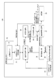
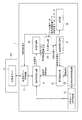
図2は、本実施形態の生体検査装置1の測定装置100の概略構成を示すブロック図である。
図2に示すように、測定装置100は、超音波センサー10と、超音波アレイ切替回路21と、送受信切替回路22と、超音波モード切替制御部23と、超音波信号発信回路24と、信号遅延回路25と、受信計測部26と、遅延時間計算部27と、記憶部28と、中央演算回路29と、を含んで構成されている。
FIG. 2 is a block diagram illustrating a schematic configuration of the
As shown in FIG. 2, the measuring
〔2−1.超音波センサーの構成〕
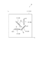
図3は、第一実施形態の超音波センサーの概略構成を示す平面図である。
図3に示すように、超音波センサー10は、矩形状の基板11を備えている。また、基板11の厚み方向から当該基板11を見た平面視において、基板11の略中心部には、超音波アレイ12(12A,12B,12C,12D)が設けられている。より具体的には、超音波センサー10は、基板11と、基板11上に積層形成される支持膜14(図4参照)とを備え、この超音波アレイ12上を覆うように、上述した音響整合部61が形成されている。
[2-1. (Configuration of ultrasonic sensor)
FIG. 3 is a plan view showing a schematic configuration of the ultrasonic sensor according to the first embodiment.
As shown in FIG. 3, the
図4は、超音波アレイを拡大した平面図、およびその断面を示す図である。
基板11の各辺の中央部には、上述したように超音波アレイ12が配置され、この超音波アレイ12は、ダイアフラム141と、圧電体15とにより構成される超音波振動子16により構成されている。
具体的には、図4に示すように、基板11は、例えば矩形状に形成されている。そして、この基板11の中心部には、超音波アレイ12の各超音波振動子16(超音波素子)のダイアフラム141を形成するための開口部111が複数形成されている。
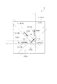
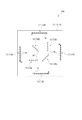
ここで、図3に示すように、矩形の1頂点を原点として、基板11上にxy軸を設定した際、超音波アレイ12Aは、x軸と平行な走査直線方向A1を有し、この走査直線方向A1に沿って配設される複数の超音波振動子16を備えている。また、超音波アレイ12Bは、y軸と平行な走査直線方向A2を有し、この走査直線方向A2に沿って配設される複数の超音波振動子16を備えている。超音波アレイ12Cは、x軸に対して45度の角度で傾斜する走査直線方向A3を有し、この走査直線方向A3に沿って配設される複数の超音波振動子16を備えている。超音波アレイ12Dは、x軸に対して135度の角度で傾斜する走査直線方向A4を有し、この走査直線方向A4に沿って配設される複数の超音波振動子16を備えている。そして、開口部111は、基板11上のこれらの超音波振動子16の配置位置に対して、それぞれ形成されている。
また、基板11には、上述のように支持膜14が積層され、上述した各開口部111は支持膜14により閉塞されている。この支持膜14のうち、開口部111を閉塞する領域によりダイアフラム141が構成される。そして、このダイアフラム141上には、圧電体15が設けられている。
なお、本実施形態では、超音波センサー10と、超音波アレイ12とにおいて、共通の基板11が用いられる例を示すが、例えば、超音波センサー10を構成する基板11上に、超音波アレイ12を構成するアレイ基板を別途配置する構成などとしてもよい。
FIG. 4 is an enlarged plan view of the ultrasonic array and a cross-sectional view thereof.
As described above, the
Specifically, as shown in FIG. 4, the
Here, as shown in FIG. 3, when the xy axis is set on the
Further, the
In the present embodiment, an example in which the
本実施形態の超音波センサー10および超音波振動子16をより具体的に説明すると、基板11は、例えばエッチングなどにより加工が容易なシリコン(Si)などの半導体形成素材により形成される。また、基板11に形成される開口部111は、平面視で例えば円形状に形成されている。なお、開口部111の平面形状として、ここでは、円形を例示するが、これに限定されず、ダイアフラム141の撓みバランスや、圧電体15によるダイアフラム141の振動安定性に応じて、例えば矩形状などその他の形状に形成されてもよい。
The
支持膜14は、基板11上で、開口部111を閉塞する状態に成膜されている。この支持膜14は、例えばSiO2膜とZrO2層との2層構造により構成されている。ここで、SiO2層は、基板11がSi基板である場合、基板表面を熱酸化処理することで成膜することができる。また、ZrO2層は、SiO2層上に例えばスパッタリングなどの手法により成膜される。ここで、ZrO2層は、後述する圧電膜152として例えばPZTを用いる場合に、PZTを構成するPbがSiO2層に拡散することを防止するための層である。また、ZrO2層は、圧電膜152の歪みに対する撓み効率が向上させるなどの効果もある。
The
圧電体15は、支持膜14の上層に積層される下部電極151と、下部電極151上に形成される圧電膜152と、圧電膜152上に形成される上部電極153とを備えている。
また、下部電極151には、例えば図4(A)に示すように、支持膜14上で走査直線方向Aに対して直交する走査直交方向に沿って延出する下部電極線151Aが接続されている。この下部電極線151Aは、各超音波振動子16に対して、それぞれ独立して設けられている。
また、上部電極153には、支持膜14上の走査直線方向Aに沿って延出する上部電極線153Aが接続されている。この上部電極線153Aは、1つの超音波アレイ12において共通電極線となる。すなわち、上部電極線153Aは、図4に示すように、隣り合う超音波振動子16の上部電極153に接続されており、端部において、例えばGNDに接続されている。これにより、各超音波振動子16の上部電極153がアースされることになる。
なお、ここでは、上部電極線153Aを超音波アレイ12における共通電極線としてGNDに接続し、下部電極線151Aをそれぞれ独立して形成することで、各超音波振動子16を個別に駆動可能となる構成を例示したが、例えば下部電極線151Aを共通電極線
としてGNDに接続し、上部電極線153Aをそれぞれ独立して形成する構成などとしてもよい。
これらの下部電極151、上部電極153、下部電極線151A,および上部電極線153Aの形成素材としては、導電性を有する金属膜であればよく、金属膜を複数層積層した積層膜を用いてもよい。なお、本実施形態では、下部電極151および下部電極線151Aとして、Ti/Ir/Pt/Ti積層膜を用い、上部電極153および上部電極線153Aとしては、Ir膜を用いている。
The
Further, for example, as shown in FIG. 4A, the
The
Here, each
As a material for forming the
圧電膜152は、例えばPZT(ジルコン酸チタン酸鉛:lead zirconate titanate)を膜状に成膜することで形成される。なお、本実施形態では、圧電膜152としてPZTを用いるが、電圧を印加することで、面内方向に収縮することが可能な素材であれば、いかなる素材を用いてもよく、例えばチタン酸鉛(PbTiO3)、ジルコン酸鉛(PbZrO3)、チタン酸鉛ランタン((Pb、La)TiO3)などを用いてもよい。
The
このような超音波振動子16では、下部電極151と、上部電極153とに電圧を印加することで、圧電膜152が面内方向に伸縮する。このとき、圧電膜152の一方の面は、下部電極151を介して支持膜14に接合され、他方の面には、上部電極153が形成される。ここで、上部電極153上には他の層が積層形成されないため、圧電膜152の支持膜14側が伸縮しにくく、上部電極153側が伸縮し易くなる。このため、圧電膜152に電圧を印加すると、開口部111側に凸となる撓みが生じ、ダイアフラム141を撓ませる。したがって、圧電膜152に交流電圧を印加することで、ダイアフラム141が膜厚方向に対して振動し、このダイアフラム141の振動により超音波が発信される。
また、超音波振動子16で超音波を受信する場合、超音波がダイアフラム141に入力されると、ダイアフラム141が膜厚方向に振動する。超音波振動子16では、このダイアフラム141の振動により、圧電膜152の下部電極151側の面と上部電極153側の面とで電位差が発生し、上部電極153および下部電極151から圧電膜152の変位量に応じた受信信号(電流)が出力される。
In such an
When receiving ultrasonic waves with the
そして、このような超音波振動子16が走査直線方向Aに沿って複数配置される超音波アレイ12では、各超音波振動子16から超音波を発信させるタイミングを遅延させてずらすことで、所望の方向に超音波の平面波を発信することが可能となる。
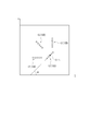
図5は、各超音波素子(1)〜(4)に入力する駆動信号を、△tだけ順に遅延させて、入力した際の超音波の発信方向(発信角度)を示す図である。
各超音波振動子16から超音波を発信させると、これらの超音波が互いに強めあう合成波面Wが形成されて伝搬される。ここで、図5に示すように、配設間隔がdに設定された各超音波素子(1)〜(4)へ入力する駆動信号を△tだけ遅延させると、先に駆動信号が入力された超音波振動子16から発信される超音波の波面と、後に駆動信号が入力された超音波振動子16から発信される波面とで、位相が異なるため、合成波面Wが走査直線方向Aに対して傾斜して伝搬される。
この時、合成波面Wの伝搬方向と、走査直線方向Aに直交する走査直交方向との発信角度をθs、音速をcとすると、次式(2)の関係が成立する。
In the
FIG. 5 is a diagram illustrating the transmission direction (transmission angle) of ultrasonic waves when the drive signals input to the ultrasonic elements (1) to (4) are sequentially delayed by Δt and input.
When ultrasonic waves are transmitted from the
At this time, if the transmission angle between the propagation direction of the combined wavefront W and the scanning orthogonal direction orthogonal to the scanning linear direction A is θs and the sound speed is c, the relationship of the following equation (2) is established.
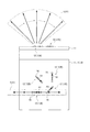
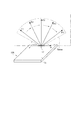
図6は、1つの超音波アレイ12のスキャンエリアを示す図である。図7は、超音波振動子16から発信される超音波のビーム形状を示す図である。図8は、超音波アレイ12の各超音波アレイ12のスキャンエリアを示す図である。なお、以降の説明にあたり、説明を分かり易くするため、図6上図のようなセンサー断面の概略図において、音響整合部61の図示を省略する。
超音波アレイ12は、上述のように、各超音波振動子16に入力する駆動信号のタイミングを遅延させることで、超音波の発信角度を変化させることができる。ここで、超音波アレイ12は、ライン状アレイ構造(1次元アレイ構造)を有しているため、超音波の発信角度は、図6に示すように、走査直線方向Aを通り、基板11に対して直交するスキャン面に制限され、スキャン面に対して交差する方向に発信角度を変化させることはできない。
FIG. 6 is a diagram showing a scan area of one
As described above, the
さらに、有限の面積を持った各超音波振動子16のダイアフラム141から発信される超音波は、図7に示すようなビーム形状(図7中、一点鎖線にて示す)となる。ここで、超音波振動子16のダイアフラム141の直径をmとし、波長λの超音波を発信した場合、ダイアフラム141からm2/4λまでの距離がフレネルゾーンとなる。このフレネルゾーンでは、超音波がほぼ平面波として伝搬させることが可能となり、フレネルゾーンを越える範囲であるフラウンホーファーゾーンでは、超音波の波面が球面状となって拡散伝搬される。超音波により血管の位置を測定する場合、フラウンホーファーゾーンでは、超音波が拡散されるため、正確な位置情報を取得することができないので、フレネルゾーン内の血管を超音波により検出することになる。
以上により、1つの超音波アレイ12により、血管位置を測定可能なスキャンエリアSは、図6に示すように、走査直線方向Aを通り、基板11に対して直交するスキャン面内で、かつ、超音波アレイ12からの距離がフレネルゾーンの範囲内(超音波アレイ12からの距離がm2/4λまでの範囲)となる扇状範囲となる。
なお、ここでは、超音波振動子16の走査直交方向の厚み寸法が十分小さいものであるため、超音波アレイ12によるスキャンエリアSは、スキャン面内としたが、例えば、超音波振動子16が走査直交方向に沿って長手状に形成される場合、スキャンエリアSは、超音波振動子16の長手方向の寸法分だけ幅寸法を有する体積領域となる。
Furthermore, the ultrasonic wave transmitted from the
As described above, the scan area S in which the blood vessel position can be measured by one
Here, since the thickness dimension in the scanning orthogonal direction of the
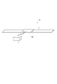
本実施形態の超音波センサー10では、上記のような超音波アレイ12が、基板11の中央部に、各走査直線方向A1〜A4が異なる方向となるように配置される。したがって、これらの4つの超音波アレイ12により、それぞれ異なる面方向を有するスキャンエリアS(S1〜S4)が分布することになる。
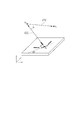
図9は、超音波センサーのスキャンエリアに血管が位置する場合の一例を示す図であり、(A)は斜視図、(B)は平面図である。なお、以降の説明にあたり、説明を分かり易くするため、図9(A)のようなセンサー概略斜視図において、音響整合部61の図示を省略する。
上記のような超音波センサー10では、その直下のスキャン可能領域Sv内に血管Kが通過する場合、4つの超音波アレイ12の各スキャンエリアSのうち少なくとも2つのエリアに血管Kが通過する。したがって、これらの超音波アレイ12から超音波を発信し、血管Kにより反射された超音波を受信することで、血管Kの位置や周波数偏移量を取得することが可能となる。
In the
9A and 9B are diagrams illustrating an example where a blood vessel is located in the scan area of the ultrasonic sensor, where FIG. 9A is a perspective view and FIG. 9B is a plan view. In the following description, the
In the
〔2−2.超音波アレイ切替回路の構成〕
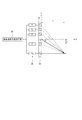
次に、図2に戻って、装置本体2の他の構成について、説明する。
超音波アレイ切替回路21は、超音波センサー10に設けられる4つの超音波アレイ12のうち、駆動させる超音波アレイ12を切り替えるスイッチング回路である。
本実施形態の生体検査装置1では、1つの超音波アレイ12から超音波の送受信が実施されている間、他の超音波アレイ12への駆動信号の出力、および他の超音波アレイ12からの受信信号の受信は実施しない。これにより、駆動対象となった超音波アレイ12では、他の超音波アレイ12から発信された超音波を受信してしまい、ノイズが検出される不都合や、駆動対象以外の超音波アレイ12から受信信号が検出されてしまう不都合を回避できる。
この超音波アレイ切替回路21は、例えば、各超音波アレイ12の下部電極線151Aおよび上部電極線153Aに接続される端子群を備え、中央演算回路29から入力されるアレイを選択する旨の切替制御信号に基づいて、切替制御信号に基づいた超音波アレイ12に対応した端子群と、送受信切替回路22とを接続する。また、駆動させない超音波アレイ12に対応した端子群は、例えば、下部電極線151Aおよび上部電極線153Aの双方をGNDに接続することで、駆動させない構成としてもよい。
[2-2. Configuration of ultrasonic array switching circuit)
Next, returning to FIG. 2, another configuration of the apparatus
The ultrasonic
In the
The ultrasonic
〔2−3.送受信切替回路の構成〕
送受信切替回路22は、超音波モード切替制御部23から入力されるモード切替信号に基づいて、接続状態を切り替えるスイッチング回路である。
具体的には、超音波モード切替制御部23から超音波発信モードに切り替える旨の制御信号が入力された場合、送受信切替回路22は、信号遅延回路25から入力された駆動信号を、超音波アレイ切替回路21に出力可能な接続状態に切り替わる。一方、送受信切替回路22は、超音波モード切替制御部23から超音波受信モードに切り替える旨の制御信号が入力された場合、超音波アレイ切替回路21から入力される受信信号を受信計測部26に出力可能な接続状態に切り替わる。
[2-3. (Configuration of transmission / reception switching circuit)
The transmission /
Specifically, when a control signal for switching to the ultrasonic transmission mode is input from the ultrasonic mode
〔2−4.超音波モード切替制御部の構成〕
超音波モード切替制御部23は、超音波アレイ12から超音波を発信させる超音波発信モードと、超音波アレイ12にて超音波を受信させる超音波受信モードと、を切り替える。
具体的には、超音波モード切替制御部23は、中央演算回路から血管状態の測定を開始する旨の制御信号が入力されると、まず、超音波モードに切り替える処理を実施する。この処理では、超音波モード切替制御部23は、送受信切替回路22に、発信モードに切り替える旨の制御信号を出力し、超音波信号発信回路24から駆動信号を出力させる旨の制御信号を出力する。また、超音波モード切替制御部23は、図示しない計時部により計測される時間を認識し、超音波発信モードから所定の発信時間経過後に、超音波受信モードに切り替える処理を実施する。ここで発信時間は、超音波アレイ12から例えば1〜2周波数のバースト波が発信される時間程度に設定されていればよい。受信モードでは、超音波モード切替制御部23は、送受信切替回路22に受信モードに切り替える旨の制御信号を出力して、送受信切替回路22を、超音波アレイ12から入力される受信信号を受信計測部26に入力可能な接続状態にスイッチングさせる。
なお、超音波モード切替制御部23は、上記処理を例えば予め設定された回数実施する。この回数は、超音波の発信角度の設定数により適宜設定される回数であり、例えば、図6に示すように、超音波の発信角度を5段階に切り替えて血管Kの位置を測定する場合、5回上記の処理を繰り返す。
なお、受信信号に基づいて、血管位置が検出できなかった場合、さらに上記処理を繰り替えしてもよい。
[2-4. Configuration of ultrasonic mode switching control unit)
The ultrasonic mode
Specifically, when a control signal for starting measurement of a blood vessel state is input from the central processing circuit, the ultrasonic mode
The ultrasonic mode
If the blood vessel position cannot be detected based on the received signal, the above process may be repeated.
〔2−5.超音波信号発信回路の構成〕
超音波信号発信回路24は、発信モードにおいて、超音波モード切替制御部23から駆動信号を出力させる旨の制御信号が入力されると、超音波アレイ12の超音波振動子16を駆動させるための駆動信号(駆動電圧)を信号遅延回路25に出力する。
[2-5. Configuration of ultrasonic signal transmission circuit)
When a control signal for outputting a drive signal is input from the ultrasonic mode
〔2−6.信号遅延回路の構成〕
信号遅延回路25は、本発明の遅延制御部を構成する。この信号遅延回路25は、超音波信号発信回路24から、各超音波振動子16に対する駆動信号が入力されると、その駆動信号を遅延させて送受信切替回路22に出力する。
ここで、信号遅延回路25は、遅延時間計算部27から入力される遅延設定信号に基づいて、各超音波振動子16を駆動させるための駆動信号を△tずつ遅延させて送受信切替回路22に出力する。
[2-6. Configuration of signal delay circuit]
The
Here, the
〔2−7.受信計測部の構成〕
受信計測部26は、計時部にて計測される時間を監視し、超音波が受信されまでの時間を計測する。なお、この受信計測部26は、本発明の周波数偏移量算出部、受信時間計測部としても機能する。
すなわち、受信計測部26は、超音波モード切替制御部23により発信モードに切り替える処理が実施されたタイミングからの時間を監視する。すなわち超音波アレイ12から超音波が発信され、超音波モード切替制御部23により、計時部でカウントされる時間がリセットされてからの時間を監視する。そして、超音波モード切替制御部23により受信モードに切り替える処理を実施され、超音波アレイ12で受信された反射超音波に応じた受信信号が送受信切替回路22から受信計測部26に入力されると、その入力されたタイミングでの時間(TOFデータ:Time Of Flightデータ)を取得し、取得したTOFデータを中央演算回路29に出力する。
[2-7. Configuration of reception measurement unit]
The
That is, the
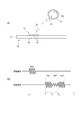
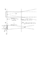
ここで、TOFデータの取得には、図10に示すタイミングで実施する。図10において、(A)は、1つの超音波アレイから血管Kに対して超音波を発信した際のモデルを示す図、(B)は、駆動信号の出力タイミングおよび受信信号のタイミングを示す図である。
図10(A)に示すように、超音波アレイ12から超音波を発信させると、この超音波は、血管Kの超音波アレイに近接する側の血管壁(第一血管壁K1と称す)で、一部が反射され、残りが血管K内に透過される。この第一血管壁K1で反射された超音波が超音波アレイ12で受信されると、超音波アレイ12は、受信信号Sig1を出力する。
また、血管K内に透過した超音波のうち、一部が血液により反射されるが、この時、血流速度に応じた周波数の偏移が起こる。この血液で反射された超音波が超音波アレイ12で受信されると、超音波アレイ12は受信信号Sig2を出力する。
さらに、血液を透過した超音波の一部は、超音波アレイ12から離間する側の血管壁(第二血管壁K2を称す)で反射される。この第二血管壁K2で反射された超音波が超音波アレイ12で受信されると、超音波アレイ12は、受信信号Sig3を出力する。
ここで、受信計測部26は、駆動信号が出力されて超音波アレイ12から超音波が出力されるタイミングを基準、すなわち0秒とし、受信信号Sig1が受信されるまでの時間T1、受信信号Sig3が受信されるまでの時間T2を計測する。そして、受信計測部26は、図10(B)に示すように、受信信号Sig1が受信された時間T1に、時間差の半値(T1−T2)/2を加算した時間T3(=T1+(T2−T1)/2)をTOFとして算出する。
また、受信計測部26は、超音波アレイ12から発信された超音波の周波数と、超音波アレイ12で受信された超音波の周波数の差である周波数偏移量△fを算出し、中央演算回路29に出力する。
Here, the TOF data is acquired at the timing shown in FIG. 10A is a diagram illustrating a model when an ultrasonic wave is transmitted from one ultrasonic array to the blood vessel K, and FIG. 10B is a diagram illustrating the output timing of the drive signal and the timing of the received signal. It is.
As shown in FIG. 10A, when an ultrasonic wave is transmitted from the
Further, some of the ultrasonic waves transmitted into the blood vessel K are reflected by the blood, but at this time, a frequency shift occurs according to the blood flow velocity. When the ultrasound reflected by the blood is received by the
Furthermore, a part of the ultrasonic wave that has passed through the blood is reflected by the blood vessel wall (referred to as the second blood vessel wall K2) on the side away from the
Here, the
The
〔2−8.遅延時間計算部の構成〕
遅延時間計算部27は、中央演算回路29から入力される発信角度データに基づいて、各超音波振動子16の駆動遅延時間を算出する。
ここで、この発信角度データは、記憶部28に予め記憶されているデータである。ここでは、図6に示すように、θs=θ1〜θ5の5つの発信角度データが予め記憶されている例を示す。なお、6個以上の発信角度データが記憶される構成としてもよく、より細かく発信角度を変化させる構成などとしてもよい。
そして、遅延時間計算部27は、入力された発信角度データθsと、予め設定されている超音波振動子16の素子ピッチdと、音速cとを用いて、上記式(1)に基づいて、遅延時間△tを算出し、遅延設定信号として信号遅延回路25に出力する。
[2-8. Configuration of delay time calculation unit]
The delay
Here, the transmission angle data is data stored in the
Then, the delay
〔2−9.記憶部の構成〕
記憶部28は、中央演算回路29や遅延時間計算部27での各種処理を実施するための各種プログラムや各種データなどを記憶する。
具体的には、各種データとして、超音波センサー10における超音波アレイ12の位置データ、発信角度データθs、TOFデータ、周波数偏移量データ、および発信超音波の周波数に関する発信周波数データなどが挙げられる。また、各種プログラムとして、血管測定処理の全体を制御する制御プログラム、超音波が反射された血管Kの1点の座標位置を演算する反射位置算出プログラム、入力された周波数偏移量データを管理する偏移量管理プログラム、血流方向(血流位置)を算出する位置算出プログラム、血流速度を算出する速度算出プログラムなどが記録される。
[2-9. (Configuration of storage unit)
The
Specifically, the various data include position data of the
〔2−10.中央演算回路の構成〕
中央演算回路29は、記憶部28に記憶されるプログラムを展開することで、各種処理を実施する。ここで、中央演算回路29は、記憶部28に記憶される偏移量管理プログラムを読み込み、処理を実施することで、本発明の最大偏移量取得部として機能する。また、中央演算回路29は、記憶部28に記憶される反射位置算出プログラムを読み込み、処理を実行することで、本発明の反射位置算出部として機能する。また、中央演算回路29は、記憶部28に記憶される位置算出プログラムを読み込み、処理を実施することで、本発明の移動方向測定部として機能する。また、中央演算回路29は、記憶部28に記憶される速度算出プログラムを読み込み、処理を実施することで、本発明の流速算出部として機能する。すなわち、中央演算回路29は、本発明の最大偏移量取得部、反射位置算出部、移動方向測定部、および流速算出部を構成する。
[2-10. Configuration of central processing circuit
The central processing circuit 29 performs various processes by expanding the program stored in the
この中央演算回路29は、例えば利用者による操作部5の操作により血管位置の測定を開始する旨の入力信号が入力された場合、超音波モード切替制御部23に測定を開始する旨の制御信号を出力する。
また、中央演算回路29は、超音波アレイ切替回路21に超音波アレイ12を切り替える旨の切替制御信号を出力する。
また、中央演算回路29は、記憶部28から発信角度データを読み込み、遅延時間計算部27に入力する。
さらに、中央演算回路29は、偏移量管理プログラムを実施することで、受信計測部から入力される周波数偏移量のうち、最大となる最大周波数偏移量を取得する処理を実施する。
さらには、中央演算回路29は、反射位置算出プログラムを実行することで、超音波が反射された位置を演算する反射位置演算処理を実施する。
さらには、中央演算回路29は、位置算出プログラムを実行することで、血管Kの位置を算出し、血流方向を特定する血流方向演算処理を実施する。
さらには、中央演算回路29は、速度算出プログラムを実行することで、最大周波数偏移量、血流方向、発信超音波の周波数に基づいて、血流速度を算出する血流速度演算処理を実施する。
そして、中央演算回路29は、上記各種処理で算出された血流速度などを表示部4に表示させる処理を実施する。
なお、各種処理の詳細については、後述の血流速測定方法において、説明する。
For example, when an input signal for starting measurement of the blood vessel position is input by the operation of the
The central processing circuit 29 outputs a switching control signal for switching the
The central processing circuit 29 reads the transmission angle data from the
Further, the central processing circuit 29 executes a deviation amount management program, thereby executing a process of obtaining the maximum maximum frequency deviation amount among the frequency deviation amounts input from the reception measurement unit.
Further, the central processing circuit 29 executes a reflection position calculation program to execute a reflection position calculation process for calculating a position where the ultrasonic wave is reflected.
Further, the central processing circuit 29 executes a position calculation program, calculates the position of the blood vessel K, and performs blood flow direction calculation processing for specifying the blood flow direction.
Furthermore, the central processing circuit 29 executes blood velocity calculation processing for calculating the blood flow velocity based on the maximum frequency shift amount, the blood flow direction, and the frequency of the transmitted ultrasonic wave by executing the velocity calculation program. To do.
Then, the central processing circuit 29 performs a process of displaying the blood flow velocity calculated by the various processes on the
Details of the various processes will be described in the blood flow rate measuring method described later.
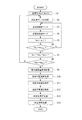
[3.生体検査装置による血流速測定方法]
次に、上記のような生体検査装置1による血流速測定方法について、図面に基づいて説明する。図11は、生体検査装置による血流速測定処置のフローチャートである。図12(A)は、1つの超音波アレイにおいて、超音波の発信角度を変化させた際のスキャンエリアを示す図であり、(B)は、受信信号から得られる周波数偏移量の変化を示す図である。図13は、図9に示すような血管に対して、各スキャンエリアと交差する血管の交差位置の一例を示す図である。図14は、超音波アレイの位置データを示す図である。
[3. Blood flow rate measurement method using a biopsy device]
Next, a blood flow rate measuring method using the above-described
本実施形態の生体検査装置1は、上述したように、生体の例えば腕などの検査対象位置に、超音波センサー10を密着させ、バンド3を締め付けて装置本体2を検査対象位置に固定する。これにより、例えば利用者が、長時間手で装置本体を保持するなどの必要がなく、容易に長期に亘る血管状態の測定を実施することが可能となる。
そして、利用者が操作部5を操作するなどして、入力信号が入力されると、生体検査装置1は、血流速測定処理を開始する。
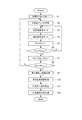
この血流速測定処理では、図11に示すように、生体検査装置1の中央演算回路29は、まず、初期化処理を実施する(ステップS1)。この初期化処理では、アレイ変数Na、角度変数Nsを初期化、すなわちNa=1,Ns=1を設定する。
次に、中央演算回路29は、アレイ変数Naの超音波アレイ12を駆動可能に切り替える処理を実施する(ステップS2)。ここで、中央演算回路29は、アレイ変数NaがNa=1の時には超音波アレイ12Aに切り替える旨の切替制御信号を超音波アレイ切替回路21に出力し、Na=2の時には超音波アレイ12Bに切り替える旨の切替制御信号を超音波アレイ切替回路21に出力し、Na=3の時には超音波アレイ12Cに切り替える旨の切替制御信号を超音波アレイ切替回路21に出力し、Na=4の時には超音波アレイ12Dに切り替える旨の切替制御信号を超音波アレイ切替回路21に出力する。
As described above, the living
And when a user operates the
In this blood flow velocity measurement process, as shown in FIG. 11, the central processing circuit 29 of the
Next, the central processing circuit 29 performs a process of switching the
この後、中央演算回路29は、本発明の超音波受発信ステップを実施する。この超音波受発信ステップでは、ステップS3の超音波発信モードにおける各種処理およびステップS4の超音波受信モードにおける各種処理が含まれる。
この超音波発信モードでは、中央演算回路29は、記憶部28から発信角度データθsを読み込み、遅延時間計算部27に出力する。ステップS1により初期化された状態では、角度変数Ns=1であるので、発信角度データθ1を読み込み、遅延時間計算部27に出力する。これにより、遅延時間計算部27は、式(1)に基づいて、遅延時間△tを算出し、遅延設定信号として信号遅延回路25に出力する。
Thereafter, the central processing circuit 29 performs the ultrasonic wave receiving / transmitting step of the present invention. This ultrasonic wave receiving / transmitting step includes various processes in the ultrasonic wave transmission mode in step S3 and various processes in the ultrasonic wave reception mode in step S4.
In this ultrasonic transmission mode, the central processing circuit 29 reads the transmission angle data θs from the
また、中央演算回路29は、超音波モード切替制御部23に超音波発信モードに切り替える旨の制御信号を出力する。超音波モード切替制御部23は、中央演算回路29から制御信号が入力されると、送受信切替回路22に、信号遅延回路25から入力される駆動信号を超音波アレイ切替回路21に出力する旨の制御信号を出力する。また、超音波モード切替制御部23は、超音波信号発信回路24に超音波アレイ12を駆動させるための駆動信号を発信する旨の制御信号を出力する。
これにより、超音波信号発信回路24から、超音波アレイ12の各超音波振動子16に出力するための駆動信号(駆動パルス)が信号遅延回路25に出力される。また、この信号遅延回路25では、上記のように、遅延時間計算部27から遅延設定信号が入力されている。このため、各駆動信号は、遅延設定信号に基づいた遅延時間だけ遅延させて送受信切替回路22に出力される。
また、送受信切替回路22は、上記のように、超音波モード切替制御部23から入力される制御信号により、信号遅延回路25から入力される駆動信号を超音波アレイ切替回路に出力する状態にスイッチングされている。このため、信号遅延回路25から出力された遅延処理済みの駆動信号は、超音波アレイ切替回路21を介して、アレイ変数Naに対応した超音波アレイ12の各超音波振動子16に出力される。
以上により、アレイ変数Naに対応した超音波アレイ12から、角度変数Nsに対応した発信角度で超音波が出力される。
Further, the central processing circuit 29 outputs a control signal for switching to the ultrasonic wave transmission mode to the ultrasonic mode
As a result, a drive signal (drive pulse) to be output from the ultrasonic
Further, as described above, the transmission /
As described above, ultrasonic waves are output from the
また、超音波モード切替制御部23は、中央演算回路29から超音波発信モードに切り替える旨の制御信号を受信して、超音波信号発信回路24から駆動信号を出力させたタイミング、すなわち、超音波アレイ12から超音波が発信されたタイミングで計時部にて計測される時間をリセットして、経過時間を計測する。そして、超音波モード切替制御部23は、例えば1〜2周期のバースト波が出力される時間後に、ステップS4の超音波受信モードの各種処理を実施する。
なお、超音波モード切替制御部23は、遅延時間計算部27により計算される遅延時間△tに基づいて、前記超音波振動子16から超音波信号の出力が終了する発信終了時間を算出し、超音波アレイ12から超音波が発信されたタイミングからこの発信終了時間の経過後に受信モードに切り替える制御を実施してもよい。
The ultrasonic mode
The ultrasonic mode
ステップS4の超音波受信モードでは、超音波モード切替制御部23は、送受信切替回路22に、超音波アレイ切替回路21から入力される受信信号を、受信計測部26に出力する旨の制御信号を出力する。
これにより、超音波アレイ12で超音波が受信されて、受信信号が超音波アレイ12から受信信号が出力されると、その受信信号が、超音波アレイ切替回路21から送受信切替回路22を経て、受信計測部26に入力可能な状態となる。
In the ultrasonic wave reception mode in step S4, the ultrasonic mode
Thereby, when an ultrasonic wave is received by the
そして、この超音波受信モードでは、受信計測部26は、送受信切替回路22から入力される受信信号を監視し、入力があった場合には、受信信号に基づいた周波数偏移量、TOFを算出する(周波数偏移量算出ステップ)。
ここで、図12における発信角度θaの場合のように、超音波の発信方向に血管Kが存在する場合、血管壁や血液で反射された超音波が超音波に受信されることで、受信信号が出力される。この場合、受信計測部26は、上述したように、血管Kの第一血管壁K1で反射された超音波に基づいた受信信号Sig1が入力されるタイミングT1と、血管Kの第二血管壁K2で反射された超音波に基づいた受信信号Sig3が入力されるタイミングT2とに基づいて、時間T3=T1+(T2−T1)/2を算出してTOFデータとして取得する。
また、上述した図10に示すように、超音波が血管K内を流れる血液で反射された場合、血流速度に応じて周波数が偏移するため、受信計測部26には、受信信号Sig1と異なる周波数の受信信号Sig2が入力される。したがって、受信計測部26は、受信信号Sig2の信号周波数と、発信信号Sig0の信号周波数との差から周波数偏移量を算出する。ここで、本実施形態では、ステップS3の超音波発信モード、およびステップS4の超音波受信モードにおける超音波送受信処理は、予め設定された周期情報に基づき、周期的に実施される。したがって、受信計測部26は、周期的に受信される超音波の受信信号を、FFT(高速フーリエ変換)を用いた演算アルゴリズムにより処理して周波数偏移量を算出する。
なお、受信信号Sig1は、発信信号の信号周期と略同一であるため、受信信号Sig1の信号周波数と、受信信号Sig2の信号周波数との差から周波数偏移量を算出する処理を実施してもよい。
また、受信計測部26は、周波数偏移量が記録される周波数偏移量データ、TOFが記録されるTOFデータ、および受信信号Sig1,Sig3の受信タイミングT1,T2が記録される受信タイミングデータを中央演算回路に出力する。中央演算回路29は、これらの周波数偏移量データ、TOFデータ、受信タイミングデータ、およびこれらのデータが入力された際のアレイ変数Na、角度変数Nsを関連付けた受信データを、適宜読み出し可能に記憶部28に記憶する。
In this ultrasonic wave reception mode, the
Here, as in the case of the transmission angle θa in FIG. 12, when the blood vessel K is present in the transmission direction of the ultrasonic wave, the ultrasonic wave reflected by the blood vessel wall or blood is received by the ultrasonic wave. Is output. In this case, as described above, the
Further, as shown in FIG. 10 described above, when the ultrasonic wave is reflected by the blood flowing in the blood vessel K, the frequency shifts in accordance with the blood flow velocity, so that the
Note that, since the received signal Sig1 has substantially the same signal cycle as the transmission signal, the process of calculating the frequency deviation amount from the difference between the signal frequency of the received signal Sig1 and the signal frequency of the received signal Sig2 may be performed. Good.
The
この後、中央演算回路29は、角度変数Nsに1を加算し(ステップS5)、角度変数Nsが最大値NsMAX以上となったか否かを判断する(ステップS6)。なお、本実施形態では、超音波アレイから超音波を5段階の角度に切り替えて発信するものとするため、NsMAX=5となる。このステップS6において、Ns≦NsMAX(本実施形態では、Ns≦5)となる場合、中央演算回路29は、ステップS3の超音波発信モードの処理に戻る。 Thereafter, the central processing circuit 29 adds 1 to the angle variable Ns (step S5), and determines whether or not the angle variable Ns is equal to or greater than the maximum value NsMAX (step S6). In the present embodiment, NsMAX = 5 because the ultrasonic waves are transmitted from the ultrasonic array while switching the angles to five levels. In this step S6, when Ns ≦ NsMAX (Ns ≦ 5 in the present embodiment), the central processing circuit 29 returns to the processing in the ultrasonic wave transmission mode in step S3.
一方、ステップS6において、Ns>NsMAX(本実施形態では、Ns>5)となる場合、角度変数Nsを初期化してNs=1を設定し、アレイ変数Naに1を加算する(ステップS7)。 On the other hand, if Ns> NsMAX (Ns> 5 in this embodiment) in step S6, the angle variable Ns is initialized and Ns = 1 is set, and 1 is added to the array variable Na (step S7).
そして、中央演算回路29は、アレイ変数Naが最大値NaMAXを超えたか否かを判断する(ステップS8)。なお、本実施形態では、超音波センサー10に4つの超音波アレイ12が設けられる例を示すため、NaMAX=4となる。
このステップS8で、アレイ変数NaがNaMAX(本実施形態では、4)以下である場合、ステップS2の処理に戻り、他の超音波アレイ12によるスキャンを実施する。これにより、図13に示すように、全ての超音波アレイ12により、スキャンエリアS1〜S4内の血管Kをスキャンすることが可能となる。
Then, the central processing circuit 29 determines whether or not the array variable Na exceeds the maximum value NaMAX (step S8). In the present embodiment, NaMAX = 4 because an example in which four
If the array variable Na is equal to or less than NaMAX (4 in this embodiment) in step S8, the process returns to step S2, and scanning with another
この後、中央演算回路29は、記憶部28から偏移量管理プログラムを読み出して実行することで、最大偏移量取得処理を実施する(ステップS9:最大偏移量取得ステップ)。
この最大偏移量取得処理では、記憶部28から受信データを読み込み、血管位置の算出や、血流の測定において、最適な受信データを取得する処理を実施する。
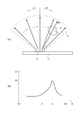
ここで、1つの超音波アレイから超音波の発信角度を切り替えて発信させ、その受信信号に基づいて周波数偏移量を算出すると、図12(B)に示すようなデータが得られる。この図12(B)に示すように、スキャンエリアS内に血管Kがある場合、超音波が血管K中の血液により反射される位置で周波数偏移量が増大し、血流速度が最も早くなる血管K中心に向かって超音波が射出される際(発信角度θa)において、周波数偏移量が最大値△faとなる。
そこで、最大偏移量取得処理では、中央演算回路29は、まず、各超音波アレイ12からそれぞれ超音波を発信させて得られる周波数偏移量データから、各超音波アレイ12に対する周波数偏移量の最大値△faをそれぞれ取得し、これを各超音波アレイ12における固有周波数偏移量とする。
そして、中央演算回路29は、これらの4つの固有周波数偏移量Δfaのうち、最大となる最大周波数偏移量△fmax、および次に大きい値の第二周波数偏移量△fnextを取得する。また、これらの最大周波数偏移量△fmaxおよび第二周波数偏移量△fnextに対応する受信データを読み込む。
ここで、最大周波数偏移量△fmaxに関連付けられたアレイ変数Naおよび角度変数Nsに対応する超音波アレイ12および発信角度が、式(1)により血流速度を算出する際に、誤差が最小となる適切な超音波入射角度を与える最適パラメータとなる。
Thereafter, the central processing circuit 29 reads out and executes the deviation amount management program from the
In this maximum deviation amount acquisition processing, received data is read from the
Here, when the transmission angle of the ultrasonic waves is switched from one ultrasonic array to be transmitted, and the frequency shift amount is calculated based on the received signal, data as shown in FIG. 12B is obtained. As shown in FIG. 12B, when there is a blood vessel K in the scan area S, the amount of frequency shift increases at the position where the ultrasonic wave is reflected by the blood in the blood vessel K, and the blood flow velocity is the fastest. When the ultrasonic wave is emitted toward the center of the blood vessel K (transmitting angle θa), the frequency shift amount becomes the maximum value Δfa.
Therefore, in the maximum deviation amount acquisition process, the central processing circuit 29 firstly calculates the frequency deviation amount for each
Then, the central arithmetic circuit 29 obtains the maximum maximum frequency deviation amount Δfmax and the next largest second frequency deviation amount Δfnext among these four natural frequency deviation amounts Δfa. Also, received data corresponding to these maximum frequency deviation amount Δfmax and second frequency deviation amount Δfnext is read.
Here, when the
次に、中央演算回路29は、記憶部28から反射位置算出プログラムを読み出し、反射位置演算処理を実施する(ステップS10)。
このステップS10の反射位置演算処理では、中央演算回路29は、最大周波数偏移量△fmaxおよび第二周波数偏移量△fnextに対応した受信データから、TOFデータ、アレイ変数Na、および角度変数Nsを読み出し、血管Kにおける2点(反射位置)を算出する。ここで、反射位置の座標は、アレイ変数Naに対応した超音波アレイ12の走査直線方向Aiがx軸(図14参照)となす角度をφiとし、角度変数Nsに対応する発信角度をθiとし、TOFをtiとした際、反射位置Viの座標(Vxi,Vyi,Vzi)は次式(3)により与えられる。中央演算回路29は、この式(3)に基づいて、血管Kの2点の反射位置を算出する。なお、φiは、記憶部28に予め記憶されている各超音波アレイ12の位置を示す位置データである。
Next, the central processing circuit 29 reads the reflection position calculation program from the
In the reflection position calculation process of step S10, the central calculation circuit 29 calculates the TOF data, the array variable Na, and the angle variable Ns from the reception data corresponding to the maximum frequency deviation amount Δfmax and the second frequency deviation amount Δfnext. And two points (reflection positions) in the blood vessel K are calculated. Here, as for the coordinates of the reflection position, the angle formed by the scanning linear direction Ai of the
次に、中央演算回路29は、記憶部28から位置算出プログラムを読み出し、血流方向演算処理を実施する(ステップS11:移動方向検出ステップ)。
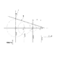
図15は、血流方向を演算するためのモデルを示す図である。図15において、V1は、最大周波数偏移量△fmaxに対応する血管Kの反射位置、V2は、第二周波数偏移量△fnextに対応する血管Kの反射位置である。
この血流方向演算処理では、中央演算回路29は、図15に示すように、ステップS10で算出された2つの反射位置座標から、ベクトル(V1V2)(又はベクトル(V2V1))を算出し、これを血流方向(血流位置)と見なす。すなわち、この血管位置測定処理では、超音波センサー10の直下領域Svが十分に小さいものであり、上記ステップS10で演算された2つ反射位置V1,V2を結ぶ直線上に、血管Kが位置しているものと見なして血管位置の測定結果とする。
Next, the central processing circuit 29 reads the position calculation program from the
FIG. 15 is a diagram illustrating a model for calculating a blood flow direction. In FIG. 15, V1 is the reflection position of the blood vessel K corresponding to the maximum frequency shift amount Δfmax, and V2 is the reflection position of the blood vessel K corresponding to the second frequency shift amount Δfnext.
In this blood flow direction calculation process, the central processing circuit 29 calculates a vector (V1V2) (or vector (V2V1)) from the two reflection position coordinates calculated in step S10, as shown in FIG. Is regarded as the blood flow direction (blood flow position). That is, in this blood vessel position measurement process, the region Sv immediately below the
この後、中央演算回路29は、記憶部28から速度算出プログラムを読み出し、血流速度演算処理を実施する(ステップS12:流速演算ステップ)。
この血流速度演算処理では、中央演算回路29は、上述した式(1)に基づいて、血液の流速を演算する。ここで、超音波入射角度γは、最大周波数偏移量△fmaxを検出した超音波アレイ12の位置をA1(図15では、超音波アレイ12Cの位置の例を示す)として、ベクトルA1V1と、ベクトルV1V2とがなす角となる。したがって、超音波入射角度γは、次式(4)の関係を満たす。
Thereafter, the central processing circuit 29 reads out the velocity calculation program from the
In this blood flow velocity calculation process, the central calculation circuit 29 calculates the blood flow velocity based on the above-described equation (1). Here, with respect to the ultrasonic incident angle γ, the position of the
したがって、上述した式(1)に、上記式(4)を代入して変形することで、次式(5)が導き出される。 Therefore, the following formula (5) is derived by substituting the above formula (4) into the above formula (1) and modifying it.
中央演算回路29は、速度算出プログラムを実行することで、最大周波数偏移量△fmax、式(4)により演算される超音波入射角度γ、音速c、超音波アレイ12から発信された超音波の周波数f0を用い、上記式(5)に基づいて、血流速v0を算出する。
The central processing circuit 29 executes the speed calculation program, thereby causing the maximum frequency deviation amount Δfmax, the ultrasonic incident angle γ calculated by Expression (4), the sound speed c, and the ultrasonic wave transmitted from the
また、生体検査装置1は、上記のようなステップS1〜ステップS12の処理を、周期的に繰り返し実施することで、長時間に亘って血管位置の経時変化を取得することが可能となる。特に、本実施形態の生体検査装置1は、バンド3により常時利用者に装着することが可能であり、上記のように、周期的に測定を実施することで、利用者の動きにより血管位置が変化した場合でも正確に血管位置を特定することができる。したがって、長期間に亘って、正確な血管位置に対する血管状態の測定が可能となる。
なお、この繰り返し処理を実施する際、生体検査装置1は、最大周波数偏移量△fmaxおよび第二周波数偏移量△fnextが検出された2つの超音波アレイ12を固定し、これらの2つの超音波アレイにより測定される受信データに基づいて、ステップS9〜ステップS12を繰り返し実施してもよい。この場合、血流速測定の度に全超音波アレイ12を用いて最大周波数偏移量△fmax,第二周波数偏移量△fnextを取得する必要がなくなり、処理を簡単にすることができ、処理負荷の軽減、処理速度の向上、省エネルギー化を図ることができる。一方、本実施形態のように、周期的に血流速測定を実施する際に、ステップS1〜S12を繰り返し実行することで、例えば利用者が普段の生活で活発に動き、血管位置がずれた場合であっても、測定の度に血管位置を正確に把握して血流速測定を実施することができるため、より精度の高い血流速測定を実施することができる。
Moreover, the
When performing this repetitive processing, the
〔4.第一実施形態の作用効果〕
上述したように、上記第一実施形態の生体検査装置1では、超音波センサー10は、基板11に走査直線方向Aがそれぞれ異なる4つの超音波アレイ12が設けられ、これらの超音波アレイ12は、それぞれ走査直線方向に沿って超音波振動子16が配設されたライン状アレイ構造に構成されている。また、生体検査装置1は、遅延時間計算部27により計算された遅延時間を信号遅延回路25に入力することで、各超音波アレイ12の各超音波振動子16に入力される駆動信号が遅延され、超音波アレイ12から出力される超音波の合成波面Wが所望の方向に制御可能な構成となり、各超音波アレイ12により、扇状のスキャンエリアを走査することが可能となっている。そして、生体検査装置1の受信計測部26は、各超音波アレイにおける周波数偏移量を取得し、中央演算回路29に出力する。また、中央演算回路29は、最大偏移量算出プログラムを読み出すことで、これらの周波数偏移量のうち最大周波数偏移量△fmaxを取得する。
ここで、この最大周波数偏移量△fmaxは、血流の流速算出時に、誤差が小さく、精度の高い演算が可能な超音波入射角度γに対応した、周波数偏移量となる。したがって、この生体検査装置1では、超音波センサー10の位置を調整して、例えば血管Kの向きに対して適切な超音波入射角度を設定するなどの煩雑な作業が不要となり、容易に、適切な超音波入射角度γに対する周波数偏移量を取得することができる。
そして、超音波センサー10は、ライン状アレイ構造の超音波アレイ12を複数備える構成であるため、例えば基板11上に2次元アレイ構造の超音波アレイを敷き詰めるような構成に比べて、アレイ構成、各超音波振動子への配線構造を簡単にでき、製造が容易であり、製造コストも低減できる。
[4. Effect of First Embodiment)
As described above, in the
Here, the maximum frequency deviation amount Δfmax is a frequency deviation amount corresponding to the ultrasonic incident angle γ with a small error and high-accuracy calculation when calculating the blood flow velocity. Therefore, in this
Since the
また、駆動させる超音波アレイを順次切り替え、発信させる超音波の発信角度も順次切り替えてスキャンを実施することで、このような最大周波数偏移量△fmaxを検出した超音波アレイ12や超音波の発信角度も容易に求まる。したがって、この最大周波数偏移量△fmaxが検出された際の超音波入射角度γも、式(4)により、演算により容易に算出することができる。
In addition, by sequentially switching the ultrasonic array to be driven and sequentially switching the transmission angle of the ultrasonic wave to be transmitted, scanning is performed, so that the
また、第一実施形態では、ステップS1〜ステップS12を周期的に繰り返すことで、長期間に亘って、生体の血流状態や血流速の経時的変化を測定することができる。したがって、1度の測定のみでは、検出できないような血流速の異常であっても、長期に亘った測定により、血流速の異常を発見することができ、利用者の健康維持を良好に支援することができる。
なお、本実施形態では、ステップS1〜S12を周期的に繰り返して長期間に亘る血流速測定を実施したが、上述のように、最大周波数偏移量△fmax、第二周波数偏移量△fnextを固定し、ステップS9〜S14のみの処理を繰り返し実施してもよく、この場合、血管位置がずれた場合に測定精度が悪化するものの、処理の高速化、処理負荷の軽減、省エネルギー化を図ることができる。
Moreover, in 1st embodiment, the temporal change of the blood flow state of a biological body and the blood flow rate can be measured over a long period of time by repeating step S1-step S12 periodically. Therefore, even if the blood flow rate is abnormal, which cannot be detected by only one measurement, the abnormal blood flow rate can be found over a long period of time, thus improving the health of the user. Can help.
In this embodiment, steps S1 to S12 are periodically repeated to measure blood flow velocity over a long period. However, as described above, the maximum frequency deviation amount Δfmax and the second frequency deviation amount Δ fnext may be fixed and only the processes of steps S9 to S14 may be repeated. In this case, although the measurement accuracy deteriorates when the blood vessel position is shifted, the processing speed is increased, the processing load is reduced, and the energy is saved. I can plan.
また、1回の血管測定において、超音波発信モードおよび超音波受信モードによる超音波の送受信は、予め設定された周期データに基づいて、周期的に実施される。このため、受信計測部26は、周期的に出力される受信信号に基づいて、FFTを用いた演算アルゴリズムにより、迅速に、かつ高精度な周波数変位量を算出することができる。
In one blood vessel measurement, transmission / reception of ultrasonic waves in the ultrasonic wave transmission mode and the ultrasonic wave reception mode is periodically performed based on preset periodic data. For this reason, the
さらに、中央演算回路29は、位置算出プログラムを実行することで、最大周波数偏移量△fmaxと関連付けられた受信タイミングデータ、および第二周波数偏移量△fnextと関連付けられた受信タイミングデータを読み込み、ベクトル(V1V2)を算出する。すなわち、生体検査装置1は、血管Kの軸方向に超音波アレイ12の走査直線方向を合わせるなどの煩雑な作業を実施することなく、演算により容易に、血管Kの位置を算出することができる。
Further, the central processing circuit 29 reads the reception timing data associated with the maximum frequency deviation amount Δfmax and the reception timing data associated with the second frequency deviation amount Δfnext by executing the position calculation program. The vector (V1V2) is calculated. That is, the
また、中央演算回路29は、速度算出プログラムを実行することで、最大周波数偏移量△fmax、発信超音波の周波数f0、および式(4)により演算される超音波入射角度γに基づいて、式(5)に基づいて、容易に血流速度を算出することができる。したがって、超音波センサー10の位置を調整して、超音波入射角度γを最適に設定するなどの煩雑な作業を不要にでき、容易に演算により精度の高い血流の流速を算出することができる。
Further, the central arithmetic circuit 29 executes the speed calculation program, and based on the maximum frequency deviation amount Δfmax, the frequency f0 of the transmitted ultrasonic wave, and the ultrasonic incident angle γ calculated by the equation (4), Based on the formula (5), the blood flow velocity can be easily calculated. Accordingly, it is possible to eliminate the troublesome work such as adjusting the position of the
[第二実施形態]
次に、本発明に係る第二実施形態の生体検査装置について、図面に基づいて説明する。
上記第一実施形態の生体検査装置1では、血管状態として血流速の測定を実施したが、第二実施形態の生体検査装置1では、血管状態として、上記血流速に加えて、血圧を測定する。なお、第二実施形態以降の説明にあたり、第一実施形態と同様の構成については同符号を付し、その説明を省略または簡略する。
[Second Embodiment]
Next, a biopsy device according to a second embodiment of the present invention will be described with reference to the drawings.
In the
〔1.生体検査装置の構成〕
この第二実施形態の生体検査装置1は、第一実施形態と略同様の構成を備えるものであり、図1に示すように、装置本体2と、装置本体2に接続されるバンド3を備えている。
また、装置本体2の内部に設けられる各種構成も第一実施形態と略同様であり、超音波センサー10と、超音波アレイ切替回路21と、送受信切替回路22と、超音波モード切替制御部23と、超音波信号発信回路24と、信号遅延回路25と、受信計測部26と、遅延時間計算部27と、記憶部28と、中央演算回路29と、を含んで構成されている。なお、第一実施形態と同様の構成については、ここでの説明は省略する。
[1. Configuration of biopsy device]
The
Various configurations provided in the apparatus
ここで、第二実施形態の記憶部28には、各種プログラムとして、制御プログラム、反射位置算出プログラム、偏移量管理プログラム、位置算出プログラム、速度算出プログラムに加え、さらに血管径算出プログラム、および血圧を算出する血圧算出プログラムが記録されている。
Here, in the
また、第二実施形態の中央演算回路29は、記憶部28に記憶される血管径算出プログラムを読み込み、処理を実施することで、本発明の径算出部として機能する。また、中央演算回路29は、記憶部28に記憶される血圧算出プログラムを読み込み、処理を実施することで、本発明の圧測定部として機能する。すなわち、中央演算回路29は、本発明の最大偏移量取得部、反射位置算出部、移動方向測定部、流速算出部、径算出部、および圧測定部を構成する。
In addition, the central processing circuit 29 of the second embodiment functions as a diameter calculation unit of the present invention by reading a blood vessel diameter calculation program stored in the
この中央演算回路29は、上記第一実施形態と同様に、例えば利用者による操作部5の操作により血管位置の測定を開始する旨の入力信号が入力された場合、超音波モード切替制御部23に測定を開始する旨の制御信号を出力する。
また、中央演算回路29は、超音波アレイ切替回路21に超音波アレイ12を切り替える旨の切替制御信号を出力する。
また、中央演算回路29は、記憶部28から発信角度データを読み込み、遅延時間計算部27に入力する。
さらに、中央演算回路29は、偏移量管理プログラムを実施することで、受信計測部から入力される周波数偏移量のうち、最大となる最大周波数偏移量を取得する処理を実施する。
さらには、中央演算回路29は、反射位置算出プログラムを実行することで、超音波が反射された位置を演算する反射位置演算処理を実施する。
さらには、中央演算回路29は、位置算出プログラムを実行することで、血管Kの位置を算出し、血流方向を特定する血流方向演算処理を実施する。
さらには、中央演算回路29は、速度算出プログラムを実行することで、最大周波数偏移量、血流方向、発信超音波の周波数に基づいて、血流速度を算出する血流速度演算処理を実施する。
これに加えて、第二実施形態の中央演算回路29は、血管径算出プログラムを実行することで、受信計測部26から入力される受信信号Sig1,Sig2の受信タイミングT1、T2に基づいて、血管径を算出する血管径演算処理を実施する。
また、中央演算回路29は、血圧算出プログラムを実行することで、血圧を算出する血圧演算処理を実施する。
そして、中央演算回路29は、上記各種処理で算出された血流速度や血圧などを表示部4に表示させる処理を実施する。
In the same way as in the first embodiment, the central arithmetic circuit 29 receives the input signal indicating that the measurement of the blood vessel position is started by the operation of the
The central processing circuit 29 outputs a switching control signal for switching the
The central processing circuit 29 reads the transmission angle data from the
Further, the central processing circuit 29 executes a deviation amount management program, thereby executing a process of obtaining the maximum maximum frequency deviation amount among the frequency deviation amounts input from the reception measurement unit.
Further, the central processing circuit 29 executes a reflection position calculation program to execute a reflection position calculation process for calculating a position where the ultrasonic wave is reflected.
Further, the central processing circuit 29 executes a position calculation program, calculates the position of the blood vessel K, and performs blood flow direction calculation processing for specifying the blood flow direction.
Furthermore, the central processing circuit 29 executes blood velocity calculation processing for calculating the blood flow velocity based on the maximum frequency shift amount, the blood flow direction, and the frequency of the transmitted ultrasonic wave by executing the velocity calculation program. To do.
In addition to this, the central processing circuit 29 according to the second embodiment executes the blood vessel diameter calculation program, and based on the reception timings T1 and T2 of the reception signals Sig1 and Sig2 input from the
In addition, the central processing circuit 29 executes a blood pressure calculation program to perform blood pressure calculation processing for calculating blood pressure.
Then, the central processing circuit 29 performs processing for displaying the blood flow velocity, blood pressure, and the like calculated by the above various processings on the
〔2.生体検査装置による血圧測定方法〕
次に、上記のような生体検査装置1による血圧測定方法について、図面に基づいて説明する。図16は、生体検査装置による血圧測定処置のフローチャートである。
図16に示すように、第二実施形態の生体検査装置1では、上記第一実施形態と同様の方法、すなわちステップS1〜ステップS12を実施することで、血流速v0を算出する。
また、第二実施形態の血圧測定では、ステップS9の最大偏移量取得処理において、固有周波数偏移量Δfaのうち、最大となる最大周波数偏移量△fmax、および次に大きい値の第二周波数偏移量△fnextに加え、最小値となる最小周波数偏移量△fmin、および次に小さい値の第三周波数偏移量△fmin_nextを取得する。
[2. Blood pressure measurement method using biopsy device]
Next, a blood pressure measurement method using the above-described
As shown in FIG. 16, in the
In the blood pressure measurement of the second embodiment, in the maximum deviation amount acquisition process in step S9, the maximum frequency deviation amount Δfmax that is the maximum among the natural frequency deviation amounts Δfa and the second value that is the next largest value. In addition to the frequency deviation amount Δfnext, the minimum frequency deviation amount Δfmin that is the minimum value and the third frequency deviation amount Δfmin_next having the next smallest value are acquired.
そして、図16に示すように、中央演算回路29は、ステップS12の血流速演算処理の後、記憶部28から血管径算出プログラムを読み込み、血管径演算処理を実施する(ステップS13:流路径取得ステップ)。これには、中央演算回路29は、ステップS9で取得した最小周波数偏移量△fminに対応する受信データから、受信タイミングデータ(受信タイミングT1,T3)を読み込み、これらの時間差(T2−T1)と、音速cとに基づいて、血管径を算出する。
なお、この血管径演算処理では、中央演算回路29は、最小周波数偏移量△fminに関連付けられる受信タイミングデータにより算出された径、第三周波数偏移量△fmin_nextに関連付けられる受信タイミングデータにより算出された径の平均値を、血管径として取得するものであってもよい。また、中央演算回路29は、4つの固有周波数偏移量△faに関連付けられる受信タイミングデータから、それぞれ径を算出し、それらの平均値を血管径としてもよい。
Then, as shown in FIG. 16, the central processing circuit 29 reads the blood vessel diameter calculation program from the
In this blood vessel diameter calculation process, the central calculation circuit 29 calculates the diameter calculated from the reception timing data associated with the minimum frequency deviation amount Δfmin and the reception timing data associated with the third frequency deviation amount Δfmin_next. The average value of the diameters may be acquired as the blood vessel diameter. Further, the central processing circuit 29 may calculate the diameters from the reception timing data associated with the four natural frequency shift amounts Δfa, and use the average value thereof as the blood vessel diameter.
この後、中央演算回路29は、記憶部28から血圧算出プログラムを読み出し、血圧演算処理を実施する(ステップS14:血圧測定ステップ)。
この血圧演算処理では、中央演算回路29は、ステップS12で算出した血流の流速v0と、ステップS13で算出した血管径Dに基づいて、血圧を演算により算出する。
Thereafter, the central processing circuit 29 reads out the blood pressure calculation program from the
In this blood pressure calculation process, the central processing circuit 29 calculates blood pressure by calculation based on the blood flow velocity v0 calculated in step S12 and the blood vessel diameter D calculated in step S13.
ここで、図17に、血管K内の血液の流れを示す図を示す。図17において、(A)は、血管Kの一部を拡大した概略図であり、(B)は血管K内の血液の速度分布を示す図である。
図17(A)に示すように、血管軸を中心軸(X軸)として、血管軸に直交する半径方向にr軸を取ったモデルを考える。血管K内を流れる血液は、静脈であれば層流であり、動脈においても末梢に近い領域では層流となる。このような、層流状態では、血管K内を流れる血液は、下記のような一般式(6)の関係式に従う。
Here, FIG. 17 shows a diagram showing the blood flow in the blood vessel K. FIG. 17A is a schematic diagram in which a part of the blood vessel K is enlarged, and FIG. 17B is a diagram showing the blood velocity distribution in the blood vessel K. FIG.
As shown in FIG. 17A, a model is considered in which the vascular axis is the central axis (X axis) and the r axis is taken in the radial direction perpendicular to the vascular axis. The blood flowing in the blood vessel K is a laminar flow if it is a vein, and a laminar flow in the region close to the periphery even in the artery. In such a laminar flow state, the blood flowing in the blood vessel K follows the relational expression of the following general formula (6).
上記式(6)において、μは流体の粘性率であり、Pは流体に係る圧力であり、uは流体の速度である。ここで、血管壁と血液の境界部分では、血流の流速は0となるため、上記式(6)から、下記式(7)が導かれる。 In the above equation (6), μ is the viscosity of the fluid, P is the pressure associated with the fluid, and u is the velocity of the fluid. Here, since the blood flow velocity is 0 at the boundary between the blood vessel wall and the blood, the following equation (7) is derived from the above equation (6).
上記式(7)は、図17(B)に示すように、血管Kの中心軸(X軸)において、血液の流速が最大となり、血管壁との境界部分で血液の流速が0となることを示している。ここで、血管Kの中心軸(X軸)を中心に、速度uを積分すると、この血管K内の断面を通過する血液の流量Qを得ることができ、下記式(8)が導き出せる。 In the above equation (7), as shown in FIG. 17B, the blood flow velocity becomes maximum at the central axis (X axis) of the blood vessel K, and the blood flow velocity becomes 0 at the boundary with the blood vessel wall. Is shown. Here, when the velocity u is integrated around the central axis (X axis) of the blood vessel K, the flow rate Q of blood passing through the cross section in the blood vessel K can be obtained, and the following equation (8) can be derived.
また、血管K内の中心軸(X軸:r=0)では、血液の流速が最大となるため、最大速度u0は、下記式(9)のように表すことができる。 In addition, since the blood flow velocity is maximum on the central axis (X axis: r = 0) in the blood vessel K, the maximum velocity u0 can be expressed by the following equation (9).
したがって、上記式(8)(9)から、血流量Qは、下記式(10)に示すように、血管径D、最大流速u0を用いて求めることが可能となる。 Therefore, from the above equations (8) and (9), the blood flow rate Q can be obtained using the blood vessel diameter D and the maximum flow velocity u0 as shown in the following equation (10).
一方、式(9)における(dP/dx)は、血管Kの中心軸方向への圧力勾配を示す式となり、例えば長さLの範囲内の血管Kの両端部の圧力をそれぞれP1,P2とすると、下記式(11)の関係が成り立つ。 On the other hand, (dP / dx) in Expression (9) is an expression indicating a pressure gradient in the direction of the central axis of the blood vessel K. For example, the pressures at both ends of the blood vessel K within the length L range are represented by P1, P2, respectively. Then, the relationship of the following formula (11) is established.
ここで、上述した式(8)に、式(11)を代入することで、下記式(12)が導かれる。 Here, the following formula (12) is derived by substituting the formula (11) into the above-described formula (8).
また、血流抵抗Rは次式(13)のように定義される。 Moreover, the blood flow resistance R is defined as the following equation (13).
この式(13)を用いることで、式(12)は、QR=P1−P2との式に置き換えることができる。また末梢血管においては、P2=0と見なすことができるため、所定の血管位置における血圧P=圧力P1とすることができる。したがって、下記式(14)が成立する。 By using this equation (13), equation (12) can be replaced with the equation QR = P1-P2. In the peripheral blood vessel, it can be considered that P2 = 0, so that blood pressure P = pressure P1 at a predetermined blood vessel position. Therefore, the following formula (14) is established.
中央演算回路29は、上記式(10)(13)(14)を用いることで、血圧を算出することができる。すなわち、中央演算回路29は、ステップS12で算出した血流の流速v0と、ステップS13で算出した血管径Dを用い、上記式(10)により、血流量Qを算出する。そして、中央演算回路29は、ステップS13で算出された血管径Dを用い、上記式(13)により、血流抵抗Rを算出する。そして、中央演算回路29は、これらの血流量Q、血流抵抗Rを用い、式(14)に基づいて、血圧Pを算出する。 The central processing circuit 29 can calculate the blood pressure by using the above equations (10), (13), and (14). That is, the central processing circuit 29 calculates the blood flow rate Q by the above equation (10) using the blood flow velocity v0 calculated in step S12 and the blood vessel diameter D calculated in step S13. Then, the central processing circuit 29 calculates the blood flow resistance R by the above formula (13) using the blood vessel diameter D calculated in step S13. Then, the central processing circuit 29 calculates the blood pressure P based on the equation (14) using the blood flow volume Q and the blood flow resistance R.
また、生体検査装置1は、第一実施形態と同様に、上記のようなステップS1〜ステップS14の処理を、周期的に繰り返し実施することで、長時間に亘って血管位置の経時変化を取得することが可能となる。特に、本実施形態の生体検査装置1は、バンド3により常時利用者に装着することが可能であり、上記のように、周期的に測定を実施することで、利用者の動きにより血管位置が変化した場合でも正確に血管位置を特定することができる。したがって、長期間に亘って、正確な血管位置に対する血管状態(血流や血圧、脈拍など)の測定が可能となる。
なお、第一実施形態と同様に、この繰り返し処理を実施する際、生体検査装置1は、最大周波数偏移量△fmaxおよび第二周波数偏移量△fnextが検出された2つの超音波アレイ12を固定し、これらの2つの超音波アレイにより測定される受信データに基づいて、ステップS9〜ステップS14を繰り返し実施してもよい。この場合、血圧測定の度に全超音波アレイ12を用いて最大周波数偏移量△fmax,第二周波数偏移量△fnextを取得する必要がなくなり、処理を簡単にすることができ、処理負荷の軽減、処理速度の向上、省エネルギー化を図ることができる。一方、本実施形態のように、周期的に血圧測定を実施する際に、ステップS1〜S14を繰り返し実行することで、例えば利用者が普段の生活で活発に動き、血管位置がずれた場合であっても、測定の度に血管位置を正確に把握して血圧測定を実施することができるため、より精度の高い血圧測定を実施することができる。
In addition, as in the first embodiment, the
As in the first embodiment, when performing this iterative process, the
〔3.第二実施形態の作用効果〕
上記第二実施形態では、上記第一実施形態の作用効果に加え、次の作用効果を奏することができる。
すなわち、中央演算回路29は、血管径プログラムにより、受信タイミングデータに基づいた血管径Dを算出し、この血管径Dと、式(5)により求められた血流の流速v0とを用いて、式(10)(13)(14)により、容易に血圧Pを算出することができる。したがって、超音波センサー10の位置を調整して、超音波入射角度γを最適に設定するなどの煩雑な作業を不要にでき、容易に演算により精度の高い血圧を算出することができる。
[3. Effect of Second Embodiment)
In the second embodiment, in addition to the functions and effects of the first embodiment, the following functions and effects can be achieved.
That is, the central processing circuit 29 calculates the blood vessel diameter D based on the reception timing data by the blood vessel diameter program, and uses the blood vessel diameter D and the blood flow velocity v0 obtained by the equation (5), The blood pressure P can be easily calculated by the equations (10), (13), and (14). Therefore, a complicated operation such as adjusting the position of the
また、第二実施形態においても、第一実施形態と同様、ステップS1〜ステップS12を周期的に繰り返すことで、長期間に亘って、生体の血流状態や血流速および血圧の経時的変化を測定することができる。したがって、1度の測定のみでは、検出できないような血流速や血圧の異常であっても、長期に亘った測定により、早期に異常を発見することができ、利用者の健康維持を良好に支援することができる。 Also in the second embodiment, similarly to the first embodiment, steps S1 to S12 are periodically repeated to change the blood flow state, blood flow rate, and blood pressure over time over a long period of time. Can be measured. Therefore, even if the blood flow velocity and blood pressure are abnormal, which cannot be detected by only one measurement, the abnormality can be discovered early by the measurement over a long period of time, and the health maintenance of the user is improved. Can help.
[第三実施形態]
次に、本発明に係る第三実施形態の測定装置である生体検査装置について、図面に基づいて説明する。
図18は、本発明に係る第三実施形態の生体検査装置の超音波センサー10Aの基板平面を示す平面図である。
[Third embodiment]
Next, a biopsy apparatus that is a measuring apparatus according to a third embodiment of the present invention will be described with reference to the drawings.
FIG. 18 is a plan view showing a substrate plane of the
上記第一実施形態および第二実施形態の生体検査装置1では、超音波センサー10から入力された受信信号に基づく受信データにより、ベクトルV1V2を求めて、血管位置の測定を実施するとともに、血管径Dの演算を行った。これに対して、第三実施形態の生体検査装置1では、超音波センサー10Aは、超音波アレイ12の外周側に、血管位置および血管径を測定するための位置測定用超音波アレイ17が配設されている。すなわち、位置測定用超音波アレイ17は、本発明の径測定用超音波アレイとしても機能する。
In the living
これらの位置測定用超音波アレイ17は、基板11の各辺の略中央部に配設されている。そして、これらの位置測定用超音波アレイ17は、複数の超音波振動子16を走査直線方向Bに沿って配設することで構成されている。ここで、位置測定用超音波アレイ17の走査直線方向Bは、当該位置測定用超音波アレイ17が配設された各辺の辺直線方向と同一方向である。本実施形態では、基板11は正方形状に形成されるため、図18に示すように、位置測定用超音波アレイ17E、17Gでは、x軸方向に沿った走査直線方向B、位置測定用超音波アレイ17F,17Hでは、y軸方向に沿った走査直線方向Bを有している。
These position measuring
また、位置測定用超音波アレイ17は、超音波アレイ12とほぼ同様の構成を有している。すなわち、基板11には、超音波アレイ12を構成する超音波振動子16のダイアフラム141を形成するための開口部111が設けられる他、各辺の中央部に、位置調整用超音波アレイ17を構成する超音波振動子16のダイアフラム141を形成するための開口部111が設けられている。ここで、位置測定用超音波アレイ17の開口部111は、超音波アレイ12の開口部111とは、例えばその開口径が異なり、異なる周波数を発信可能な構成となっている。すなわち、超音波アレイ12では、例えば2Hzの超音波が出力可能であり、ドプラ効果による周波数偏移量が取得し易い周波数が出力可能に形成されている。一方、位置測定用超音波アレイ17では、例えば10Hzの超音波が出力可能であり、超音波の波長が短いため、血管位置や血管径の検出が容易な周波数を出力可能に形成されている。
The position measurement
図19は、1つの位置測定用超音波アレイ17のスキャンエリアを示す図である。
位置測定用超音波アレイ17は、超音波アレイ12と同様に、信号遅延回路25から出力される遅延済み駆動信号により、超音波の発信角度が制御可能であり、これにより、図19に示すように、走査直線方向Bを通り、かつ基板11の面に直交する面内で、扇状のスキャンエリアSareaを有する。第二実施形態では、このような位置測定用超音波アレイ17が各辺に対して設けられているため、各辺を覆うようにスキャンエリアSareaが形成される。すなわち、基板11の直下領域の側面は、各位置測定用超音波アレイ17のスキャンエリアSareaに囲われることになる。このようなスキャンエリアSareaを有する超音波センサー10Aでは、基板11の直下領域に血管Kが通過する場合、これらのスキャンエリアSareaの少なくとも2つに血管Kが交差する。したがって、その交差点を超音波により検出することで、血管位置を演算することが可能となる。
FIG. 19 is a diagram showing a scan area of one position measurement
As in the
このような第二実施形態の生体検査装置1では、記憶部28に記憶される位置算出プログラム、速度算出プログラム、および血管径算出プログラムは、中央演算回路29に、第一実施形態と異なる処理を実施させる。以下、これらのプログラムによる中央演算回路29の処理について説明する。
In the
中央演算回路29は、位置算出プログラムにより、位置測定用超音波アレイ17から出力された受信データに基づいた血管位置を演算する血流方向演算処理を実施する。
具体的には、第二実施形態における血流方向演算処理では、中央演算回路29は、位置測定用超音波アレイ17から出力された受信データを読み込み、そのTOFデータを取得する。そして、これらのTOFデータに基づいて、血管K上の2点、すなわち位置測定用超音波アレイ17から発信された超音波が反射された2点を算出し、これらの2点を結ぶ直線を仮血管位置として算出する。
また、中央演算回路29は、反射位置演算処理では、最大周波数偏移量△fmaxに関連付けられたTOFデータに基づいて反射位置V1,V2を算出し、これらの反射位置V1,V2が仮血管位置上に位置するか否かを判断する。ここで、中央演算回路29は、これらの反射位置V1,V2が仮血管位置上に位置していると判断すると、仮血管位置を血管位置として取得する。一方、これらの反射位置V1,V2が仮血管位置上に位置していない場合、位置測定用超音波アレイ17により検出された2つの反射位置と、点V1,V2とを通る線を血管位置として補正する。この場合、血管Kの軸方向は直線とならず、曲線となる。
The central processing circuit 29 performs blood flow direction calculation processing for calculating the blood vessel position based on the received data output from the position measurement
Specifically, in the blood flow direction calculation process in the second embodiment, the central calculation circuit 29 reads the reception data output from the position measurement
In the reflection position calculation process, the central processing circuit 29 calculates the reflection positions V1 and V2 based on the TOF data associated with the maximum frequency shift amount Δfmax, and these reflection positions V1 and V2 are the temporary blood vessel positions. Judge whether it is located above. Here, if the central processing circuit 29 determines that these reflection positions V1 and V2 are located on the temporary blood vessel position, it acquires the temporary blood vessel position as the blood vessel position. On the other hand, when these reflection positions V1 and V2 are not located on the temporary blood vessel position, a line passing through the two reflection positions detected by the position measurement
また、中央演算回路29は、速度算出プログラムにより、血流速度演算処理を実施する。ここで、上記血流方向演算処理により、反射位置V1,V2が仮血管位置上に位置していると判断された場合、上記第一実施形態と同様の処理を実施する。
一方、血流方向演算処理により、反射位置V1,V2が仮血管位置上に位置していないと判断された場合、血管Kの軸方向における反射位置V1での接線方向を血流方向として判断し、この接線方向と、ベクトルA1V1とのなす角度γを算出する。その後は、第一および第二実施形態と同様に、式(5)に基づいて、血流の流速v0を算出する。
In addition, the central processing circuit 29 performs blood flow velocity calculation processing by a velocity calculation program. Here, when it is determined by the blood flow direction calculation processing that the reflection positions V1 and V2 are located on the temporary blood vessel position, the same processing as in the first embodiment is performed.
On the other hand, when it is determined by the blood flow direction calculation processing that the reflection positions V1 and V2 are not located on the temporary blood vessel position, the tangential direction at the reflection position V1 in the axial direction of the blood vessel K is determined as the blood flow direction. Then, an angle γ formed by the tangential direction and the vector A1V1 is calculated. Thereafter, similarly to the first and second embodiments, the blood flow velocity v0 is calculated based on the equation (5).
さらに、中央演算回路29は、血管径算出プログラムは、位置測定用超音波アレイ17からの受信信号に基づいた受信データを読み込み、受信タイミングデータから、血管径Dを算出する。
Further, the central processing circuit 29 reads the reception data based on the reception signal from the position measurement
〔第三実施形態の作用効果〕
上述したような第三実施形態の生体検査装置では、超音波センサー10Aは、位置測定用超音波アレイ17を備えており、この位置測定用超音波アレイ17から出力された受信信号に基づいて、血管位置の測定を実施する。
超音波アレイ12から、1つの周波数の超音波を発信して、血管位置や血管径の測定用のTOFデータや受信タイミングデータと、血流速測定用の周波数偏移量との双方を取得する場合、血管壁や血液での超音波の反射率が異なるため、いずれか一方のデータに誤差が生じやすくなる。これに対して、第三実施形態では、位置測定用超音波アレイ17を設けることで、血管位置や血管径を測定するための周波数の超音波と、周波数偏移量を測定するための周波数の超音波とをそれぞれ別の素子から発信させることができる。したがって、位置測定用超音波アレイ17から出力された受信信号を用いることで、より正確な血管位置、血管径を測定することができ、超音波アレイ12から出力される受信信号を用いることで、より正確な周波数偏移量を測定することができる。これにより、より正確な血流速度、血圧を算出することができ、測定精度を向上させることができる。
[Operational effects of the third embodiment]
In the living body inspection apparatus of the third embodiment as described above, the
The
[第四実施形態]
次に、本発明に係る第四実施形態の生体検査装置について、図面に基づいて説明する。
第四実施形態の生体検査装置は、第一実施形態および第二実施形態の生体検査装置1の超音波アレイ12の構造を変形したものであり、その他の構成については上記第一実施形態および第二実施形態の生体検査装置1と同様である。
図20は、第四実施形態の生体検査装置の超音波センサー10Bの基板11の平面図である。
[Fourth embodiment]
Next, a biopsy device according to a fourth embodiment of the present invention will be described with reference to the drawings.
The biopsy device of the fourth embodiment is a modification of the structure of the
FIG. 20 is a plan view of the
第四実施形態の生体検査装置の超音波センサー10Bには、第一実施形態と同様に、基板11の中央部に、それぞれ超音波アレイ31(31A,31B,31C,31D)が配置される。
ここで、各超音波アレイ31は、第一実施形態と同様に、それぞれ異なる走査直線方向Aを有しており、これらの走査直線方向Aに沿って、複数の超音波素子32が配設されている。また、各超音波素子32は、走査直線方向Aに直交する走査直交方向に沿って配設された複数(本実施形態では3つの例を示す)の超音波振動子16を備えている。なお、各超音波振動子16の構成は、第一実施形態の超音波振動子16と同様の構成であり、ここでの説明は省略する。
In the
Here, as in the first embodiment, each
1つの超音波素子32において、例えば、各超音波振動子16の上部電極線153Aが共通電極として互いに接続され、各超音波振動子16の各下部電極151に接続される下部電極線151Aがそれぞれ独立して配線されている。すなわち、これらの超音波振動子16は、それぞれ独立して駆動させることが可能に構成されている。
なお、1つの超音波アレイ31において、全ての上部電極線153Aが結線されて共通電極線となる構成としてもよい。
In one
In the single
このような、超音波アレイ31では、各超音波素子32における各超音波振動子16の超音波出力タイミングを制御することで、所定の1点に超音波を集束させることが可能となる。これにより、超音波の平面波を出力可能なフレネルゾーンを拡大することができ、超音波振動子16から超音波が平面波として伝搬される距離を延ばすことができる。
図21は、1つの超音波振動子により出力される超音波のフレネルゾーン(上図)と、第二実施形態の超音波アレイのフレネルゾーン(下図)と、の差を示す図である。
図21の上図に示すように、上記第一実施形態で示したような単一の超音波振動子16から発信される超音波では、距離L1=D2/4λまでがフレネルゾーンとなり、平面波が伝搬される。これに対して、図12の下図に示すように、中央の超音波素子32から超音波を発信するタイミングを、両端部の超音波素子32から発信される超音波の発信タイミングから遅延させることで、各超音波振動子16から出力される超音波の合成波が、遅延時間に応じたフォーカス点Pに向かって集束するように形成される。すなわち、各超音波振動子16の超音波発信タイミングを制御することで、フォーカス点Pの位置を制御でき、フレネルゾーンの距離(すなわち、超音波が平面波として伝搬される距離)L2を所望の距離に調整することが可能となる。
In such an
FIG. 21 is a diagram showing the difference between the Fresnel zone (upper diagram) of the ultrasonic wave output by one ultrasonic transducer and the Fresnel zone (lower diagram) of the ultrasonic array of the second embodiment.
As shown in the upper diagram of FIG. 21, in the ultrasonic wave transmitted from the single
このような遅延時間の制御は、中央演算回路29、遅延時間計算部27および信号遅延回路25により実施することが可能である。その遅延時間の算出方法を図22に基づいて説明する。
図22は、複数の超音波振動子16から発信した超音波を所定の1点に集束させた状態を示す図である。図22に示す例のように、1〜Nの超音波振動子16が配置されており、各超音波振動子16における超音波発信タイミングを調整することで、フォーカス点Pに超音波を集束させる場合、任意の点Yiの位置にある超音波振動子16からフォーカス点Pに超音波が到達するまでの時間τ(i,F)は、以下の式(15)により表すことができる。
Such control of the delay time can be performed by the central processing circuit 29, the delay
FIG. 22 is a diagram illustrating a state in which the ultrasonic waves transmitted from the plurality of
この式(15)は、図22に示すように、超音波素子32の中央点を原点(0,0)とし、超音波振動子16のy軸に沿って配設し、x方向に超音波を発信した場合における演算式である。上記式(5)において、Fは、フォーカス点のx座標位置、θは、超音波素子32の中心点(原点)とフォーカス点Pとを通る直線と、x軸とのなす角度である。
As shown in FIG. 22, this equation (15) is arranged along the y-axis of the
第四実施形態の生体検査装置では、上記式(15)に基づいて、中央演算回路29、遅延時間計算部27、および信号遅延回路25は、各超音波振動子16に印加する駆動信号の出力タイミングを制御して、超音波の発信タイミングを遅延させる。
すなわち、第四実施形態の生体検査装置では、中央演算回路29は、血管Kが位置する深さに応じて、超音波を集束させるフォーカス点Pを設定して、遅延時間計算部27に出力する。これにより、遅延時間計算部27は、上記式(15)に基づいて、各超音波振動子16から出力させる超音波をフォーカス点Pで集束させるための遅延時間を計算し、信号遅延回路25に入力する。
ここで、血管Kが位置する深さとは、例えば利用者が操作部5を操作することで入力されるものであればよい。例えば、皮膚から血管Kまでの距離が短い指などを検査部位とする場合で、利用者の操作部5の操作により指を検査対象とする旨の入力信号が入力されると、中央演算回路29は、遅延時間計算部27に小さい値のF値(フォーカス点Pまでの距離)を出力する。また、例えば、皮膚から血管Kまでの距離が長くなる腕などを検査部位とする場合で、利用者の操作部5の操作により腕を検査対象とする旨の入力信号が入力されると、中央演算回路29は、より大きい値のF値を遅延時間計算部27に出力する。また、例えば、皮膚から血管Kまでの距離がさらに長くなる脚などを検査部位とする場合で、利用者の操作部5の操作により脚を検査対象とする旨の入力信号が入力されると、中央演算回路29は、さらに大きい値のF値を遅延時間計算部27に出力する。ここで、これらのF値としては、予め設定され、記憶部28に記憶される値を用いることができる。なお、例えば指を検査部位とする場合などでは、1つの超音波素子32を構成する各超音波振動子16間では、超音波の発信タイミングを遅延させず、上記第一実施形態と同様のフレネルゾーンにより血管位置を検出する構成などとしてもよい。
In the biopsy device of the fourth embodiment, based on the above equation (15), the central processing circuit 29, the delay
That is, in the biopsy device of the fourth embodiment, the central processing circuit 29 sets a focus point P for focusing the ultrasonic wave according to the depth at which the blood vessel K is located, and outputs the focus point P to the delay
Here, the depth at which the blood vessel K is located may be any depth that is input by the user operating the
なお、この超音波センサー10Bにおいても、第三実施形態のような位置測定用超音波アレイ17を別途設ける構成としてもよく、この場合、位置測定用超音波アレイ17においても、走査直線方向Bに直交する方向に複数の超音波振動子16を配設したアレイ構造とし、フレネルゾーンを拡大して、超音波が平面波として伝搬される距離を延長可能な構成とすることで、より広い範囲の血管Kの位置測定を実施することができる。
The
〔第四実施形態の作用効果〕
上記第四実施形態の生体検査装置では、各超音波アレイ31は、走査直線方向Aに沿って配設されたライン状アレイ構造の超音波素子32を備えるとともに、これらの超音波素子32は、それぞれ走査直線方向Aに直交する走査直交方向に配設された超音波振動子16を備えている。そして、遅延時間計算部27および信号遅延回路25は、中央演算回路29から入力される最適F値に基づいて、各超音波素子32の走査直交方向に配設された各超音波振動子16に対し、両端部の超音波振動子16から中央部の超音波振動子16に向かうに従って、超音波の発信タイミングを遅延させる駆動信号を出力する。
このため、各超音波振動子16から発信される超音波のフレネルゾーンの距離(すなわち、超音波が平面波として伝搬される距離)L2を、単一の超音波振動子16を用いる場合に比べて延ばすことができ、血管位置のスキャンエリアSareaをより大きくすることができる。したがって、生体検査装置は、より広い領域に対して血管Kの位置測定を実施することができる。
[Effects of the fourth embodiment]
In the biological examination apparatus of the fourth embodiment, each
For this reason, the distance between the Fresnel zones of ultrasonic waves transmitted from each ultrasonic transducer 16 (that is, the distance by which the ultrasonic waves are propagated as a plane wave) L2 is set as compared with the case where a single
[第五実施形態]
次に、本発明に係る第五実施形態の生体検査装置について、図面に基づいて説明する。
第五実施形態は、第一実施形態や第二実施形態の生体検査装置1の超音波アレイ12の
配置位置を変形したものであり、その他の構成については上記第一実施形態および第二実施形態の生体検査装置1と同様である。
図23は、第五実施形態の超音波センサー10Cの概略構成を示す平面図である。
[Fifth embodiment]
Next, a biopsy device according to a fifth embodiment of the present invention will be described with reference to the drawings.
The fifth embodiment is obtained by modifying the arrangement position of the
FIG. 23 is a plan view showing a schematic configuration of an ultrasonic sensor 10C according to the fifth embodiment.
この第五実施形態の生体検査装置では、超音波センサー10Cの基板11上に、走査直線方向Aがそれぞれ異なる超音波アレイ12が、8個配設されている。具体的には、超音波アレイ12Aは、x軸と平行な走査直線方向A1を有し、この走査直線方向A1に沿って配設される複数の超音波振動子16を備えている。また、超音波アレイ12Bは、y軸と平行な走査直線方向A2を有し、この走査直線方向A2に沿って配設される複数の超音波振動子16を備えている。超音波アレイ12Cは、x軸に対して45度の角度で傾斜する走査直線方向A3を有し、この走査直線方向A3に沿って配設される複数の超音波振動子16を備えている。超音波アレイ12Dは、x軸に対して135度の角度で傾斜する走査直線方向A4を有し、この走査直線方向A4に沿って配設される複数の超音波振動子16を備えている。超音波アレイ12Eは、x軸に対して30度の角度で傾斜する走査直線方向A5を有し、この走査直線方向A5に沿って配設される複数の超音波振動子16を備えている。超音波アレイ12Fは、x軸に対して60度の角度で傾斜する走査直線方向A6を有し、この走査直線方向A6に沿って配設される複数の超音波振動子16を備えている。超音波アレイ12Gは、x軸に対して120度の角度で傾斜する走査直線方向A7を有し、この走査直線方向A7に沿って配設される複数の超音波振動子16を備えている。超音波アレイ12Hは、x軸に対して135度の角度で傾斜する走査直線方向A8を有し、この走査直線方向A8に沿って配設される複数の超音波振動子16を備えている。
In the biopsy device of the fifth embodiment, eight
このような超音波センサー10Cを備えた生体検査装置では、8個の超音波アレイ12から出力される周波数偏移量に基づいて、最大周波数偏移量△fmaxを取得することができる。したがって、多くのデータからより血流測定に適したデータを取得することができ、より精度が高く、誤差が少ない血流速度を演算により求めることができる。
In the living body inspection apparatus provided with such an ultrasonic sensor 10C, the maximum frequency deviation amount Δfmax can be acquired based on the frequency deviation amounts output from the eight
[第六実施形態]
次に、本発明に係る第六実施形態の生体検査システム1Aについて図面に基づいて説明する。図24は、本発明に係る第六実施形態の生体検査システム1Aの概略を示す斜視図である。
図24において、第六実施形態の生体検査システム1Aは、超音波センサー10Dと、バンド3と、制御装置7と、を備えており、これらの超音波センサー10Dおよび制御装置7により本発明の測定装置を構成する。図25は、第六実施形態の生体検査システム1Aの概略構成を示すブロック図である。
この生体検査システム1Aでは、膜状に形成される超音波センサー10Dを生体の所定の検査位置にバンドで固定し、超音波センサー10Dから出力される信号を制御装置7により処理する。なお、図24では、図示を省略しているが、超音波センサー10Dの表層には、音響整合部61が形成されている。
また、制御装置7には、図25に示すように、超音波アレイ切替回路21、送受信切替回路22、超音波モード切替制御部23、超音波信号発信回路24、信号遅延回路25、受信計測部26、遅延時間計算部27、記憶部28、中央演算回路29などが組み込まれている。
なお、制御装置7に設けられる各構成については、上記第一実施形態と同様であるため、ここでの説明は省略する。
また、制御装置7に利用者が生体検査システム1Aを操作するための操作部5や表示部4が設けられる構成としてよく、制御装置7に操作部5や表示部4が接続可能な構成としてもよい。
[Sixth embodiment]
Next, a
In FIG. 24, the
In this living
25, the
In addition, about each structure provided in the
Further, the
なお、図24では、超音波センサー10Dを制御装置7が有線により接続される例を示すが、例えば、赤外線、Bluetooth(登録商標)、電波などにより、無線接続される構成としてもよく、この場合、超音波センサー10Dおよび制御装置7には、それぞれ、無線通信を実施する無線通信部が設けられる。このような構成とする場合、超音波センサー10Dを装着時に線が邪魔になることがなく、より携帯利便性に優れた生体検査システム1Aを提供できる。
FIG. 24 shows an example in which the
上述のような第五実施形態の生体検査システム1Aでは、薄型の超音波センサー10Dのみを生体に固定するため、長時間に亘って血管状態を検査する場合であっても、生体検査システム1Aが邪魔になったり、重量により生体に負荷をかけたりすることがない。したがって、例えば利用者は、普段の生活を続けながら血管状態の変化を測定することができる。
In the living
〔その他の実施形態〕
なお、本発明は前述の実施形態に限定されるものではなく、本発明の目的を達成できる範囲での変形、改良等は本発明に含まれるものである。
[Other Embodiments]
It should be noted that the present invention is not limited to the above-described embodiments, and modifications, improvements, and the like within the scope that can achieve the object of the present invention are included in the present invention.
例えば、上記第一〜第六実施形態では、測定装置として、生体内の血管K内を流れる血液の流速や血圧を測定する生体検査装置1、生体検査システム1Aを例示したが、これに限定されない。例えば、超音波を伝達可能な収納体の内部に、収納体と異なる音響インピーダンスを有する管が設けられており、その管内に流れる被測定流体の流速や圧力を測定する測定装置であれば本発明を適用することができる。例えば、液体内に配設された配管の位置や、配管内の被測定流体の流速や圧力を測定する測定装置などに本発明を適用することができる。
For example, in the first to sixth embodiments, the
また、上記第一〜第六実施形態において、超音波振動子16は、支持膜14上に、膜状の下部電極151、圧電膜152、上部電極153を積層することで構成される例を示したが、これに限定されず、例えばバルク状(塊状)の圧電体を支持膜14上に配置する構成などとしてもよい。この場合、バルク状圧電体としては、カット成形が容易な長方形状に形成し、長方形の長手方向を走査直交方向に沿わせ、かつ走査直線方向Aに沿って複数の圧電体を配置する。
In the first to sixth embodiments, an example in which the
さらに、上記第一〜第六実施形態において、超音波振動子16として、ダイアフラム141の形状が円形で、円形状の圧電体15を形成する構成を例示したが、これに限定されず、例えば矩形状や、多角形状などのダイアフラム141に、矩形状や多角形状などの圧電体15を設ける構成としてもよい。すなわち、ダイアフラム141の振動時の応力バランスなどを考慮して、超音波振動子16の形状を自由に設計することができる。
また、1つの超音波振動子16により超音波の送信および受信の双方を実施する例を示したが、例えば超音波送信用の振動子と、超音波受信用の振動子とを別素子として備える構成などとしてもよい。
Further, in the first to sixth embodiments, the
Further, although an example in which both transmission and reception of ultrasonic waves are performed by one
さらには、上記第一〜第六実施形態において、超音波センサー10の基板11を矩形状(正方形状)に形成する例を示したが、これに限定されず、その他の多角形状や、円形、楕円形状など、いかなる形状に成形してもよい。
また、第三実施形態において、基板11が多角形状の場合、各辺に対してそれぞれ位置測定用超音波アレイ17を配設することで、また、基板が円形や楕円形の場合では、走査直線方向Bが、基板11の接線方向に沿うように、位置測定用超音波アレイ17を配設することで、超音波センサー10Aの直下領域を通過する血管Kの位置を測定することができる。
Furthermore, in the said 1st-6th embodiment, although the example which forms the board |
In the third embodiment, when the
第一〜第六実施形態において、ステップS10の反射位置演算処理では、中央演算回路29は、第二周波数偏移量△fnextに対応した受信データから、反射位置V2を算出したが、例えば、その他の固有周波数偏移量△faに対応した受信データから、反射位置V2を算出してもよい。 In the first to sixth embodiments, in the reflection position calculation process in step S10, the central processing circuit 29 calculates the reflection position V2 from the reception data corresponding to the second frequency shift amount Δfnext. The reflection position V2 may be calculated from the received data corresponding to the natural frequency deviation amount Δfa.
そして、第四実施形態では、生体検査装置1が装着される位置が設定入力されることで、中央演算回路29で最適なF値を選択して遅延時間計算部27に出力し、遅延時間計算部27で各超音波素子32を構成する各超音波振動子16に対して出力する駆動信号の遅延時間を算出する構成を例示したがこれに限定されない。例えば、血管状態の検査対象が予め設定された位置、例えば腕の血管状態の検査専用の生体検査装置1などでは、遅延時間計算部27は、予め設定された最適F値に基づいて、遅延時間を計算する構成などとしてもよい。
In the fourth embodiment, the position at which the
また、第一〜第六実施形態において、1つの走査直線方向Aに対して1つの超音波アレイ12が配設される例を示したが、例えば、1つの走査直線方向Aに対して複数の超音波アレイ12が配置される構成などとしてもよい。
In the first to sixth embodiments, an example in which one
さらに、第六実施形態において、制御装置7内に、超音波アレイ切替回路21、送受信切替回路22、超音波モード切替制御部23、超音波信号発信回路24、信号遅延回路25、受信計測部26、遅延時間計算部27、記憶部28、中央演算回路29が含まれる構成を例示したがこれに限定されない。例えば、超音波センサー10Dに、超音波アレイ切替回路21や送受信切替回路22、信号遅延回路25などの回路を設ける構成としてもよい。超音波センサー10Dに各回路が構成される場合、例えば基板11上に形成することで、超音波センサー10Dの厚み寸法の増大を抑えることができる。
Further, in the sixth embodiment, the
そして、上記第一〜第六実施形態において、各超音波アレイ12は、各超音波振動子16により超音波の発信および受信の双方を実施し、超音波モード切替制御部23により、超音波発信モードと、超音波受信モードとを切り替える例を示したが、これに限定されない。
例えば、各超音波アレイ12を構成する超音波振動子16のうち、奇数番目に配置される超音波振動子16を超音波発信用の素子として用い、偶数番目に配置される超音波振動子16を超音波受信用の素子として用いてもよい。また、超音波アレイ12のライン一端側の超音波振動子16から超音波を発信し、ライン他端側の超音波振動子16で超音波を受信する構成などとしてもよい。
さらには、超音波発信専用の超音波振動子と、超音波受信専用の超音波振動子とがそれぞれ別体として設けられる構成としてもよい。
この場合、図26に示すように、複数の超音波発信専用振動子161が直線上に配列された超音波発信用アレイ121と、超音波受信専用振動子162が直線上に配列された超音波受信用アレイ122とが、並設される構成などとしてもよい。
In the first to sixth embodiments, each
For example, among the
Furthermore, an ultrasonic transducer dedicated to ultrasonic transmission and an ultrasonic transducer dedicated to ultrasonic reception may be provided as separate bodies.
In this case, as shown in FIG. 26, an
また、上記のような変形例の測定システムや、第五実施形態の生体検査システム1Aにおいて、制御装置7は、例えばインターネット回線を介して接続されるサーバー装置にデータを送信する構成であってもよく、この場合、例えば病院などの医療施設で超音波センサー10Dを装着した患者の血管状態を常時監視することができる。
Further, in the measurement system of the modified example as described above and the
第二実施形態において、中央演算回路29は、血流方向演算処理の際に、位置測定用超音波アレイ17の受信信号に基づく反射位置座標により演算された血管位置上に、最大周波数偏移量△fmaxと関連付けられたTOFデータに基づいて演算された反射位置V1がない場合、位置測定用超音波アレイ17の受信信号に基づく反射位置座標と、超音波アレイ12の受信信号に基づく反射位置V1,V2により血管位置を補正する例を示したがこれに限定されない。例えば、位置測定用超音波アレイ17から出力される受信信号に基づく受信データのみにより血管位置を演算し、V1座標を、この血管位置上の移動させる補正を行ってもよい。
In the second embodiment, the central processing circuit 29 performs the maximum frequency shift amount on the blood vessel position calculated from the reflection position coordinates based on the received signal of the position measurement
さらに、上記実施形態において、遅延時間計算部27が、中央演算回路29から発信角度データを受け取ることで、各超音波振動子16に入力する駆動信号の遅延時間を演算する装置である例、すなわち、遅延時間計算部27がハードウェアとして構成される例を示したが、これに限定されない。例えば、記憶部28に遅延時間計算プログラムが記憶され、中央演算回路29によりこの遅延時間計算プログラムが読み出されて実行されることで、各駆動信号に遅延時間を演算する構成としてもよい。
また、本発明の最大偏移量取得部、反射位置算出部、移動方向測定部、流速算出部、径算出部、および圧測定部として、中央演算回路29が偏移量管理プログラム、反射位置算出プログラム、位置算出プログラム、速度算出プログラム、血管径算出プログラム、および血圧算出プログラムを読み出し実行することで機能する例を示したが、例えば、最大偏移量取得部、反射位置算出部、移動方向測定部、流速算出部、径算出部、および圧測定部が、例えばICなどの集積回路により、ハードウェアとして構成されるものであってもよい。
Furthermore, in the above embodiment, the delay
Further, as the maximum deviation amount acquisition unit, reflection position calculation unit, movement direction measurement unit, flow velocity calculation unit, diameter calculation unit, and pressure measurement unit of the present invention, the central arithmetic circuit 29 has a deviation amount management program, reflection position calculation. Although an example of functioning by reading and executing a program, a position calculation program, a speed calculation program, a blood vessel diameter calculation program, and a blood pressure calculation program has been shown, for example, a maximum deviation amount acquisition unit, a reflection position calculation unit, a movement direction measurement The unit, the flow velocity calculation unit, the diameter calculation unit, and the pressure measurement unit may be configured as hardware by an integrated circuit such as an IC.
以上、本発明を実施するための最良の構成について具体的に説明したが、本発明は、これに限定されるものではない。すなわち、本発明は、主に特定の実施形態に関して特に図示され、かつ、説明されているが、本発明の技術的思想および目的の範囲から逸脱することなく、以上述べた実施形態に対し、当業者が様々な変形および改良を加えることができるものである。 Although the best configuration for carrying out the present invention has been specifically described above, the present invention is not limited to this. That is, the present invention has been illustrated and described primarily with respect to particular embodiments, but the present invention is not limited to the embodiments described above without departing from the scope of the technical idea and object of the present invention. Various modifications and improvements can be made by a trader.
1…測定装置である生体検査装置、1A…測定装置である生体検査システム、7…制御装置、10,10A,10B,10C,10D…超音波センサー、11…基板、12,31…超音波アレイ、16…超音波振動子、17…径測定用超音波アレイとしても機能する位置測定用超音波アレイ、25…遅延制御部を構成する信号遅延回路、26…周波数偏移量算出部である受信計測部、29…プログラムを読み込み実行することで最大偏移量取得部、反射位置算出部、移動方向測定部、流速算出部、径算出部、および圧測定部として機能する中央演算回路、32…超音波素子、A…走査直線方向。
DESCRIPTION OF
Claims (15)
前記第1の超音波素子アレイに配置された複数の第1の超音波素子、または前記第2の超音波素子アレイに配置された複数の第2の超音波素子による、発信超音波の発信と受信超音波の受信とを行う送受信部と、
前記送受信部で受信される前記受信超音波に基づいて演算を実施する演算部と、を具備し、
複数の前記第1の超音波素子アレイは、複数の前記第1の超音波素子を有し、かつ、複数の前記第1の超音波素子アレイの方向が前記基板において互いに異なる方向となるように互いに離間した位置に配設され、
複数の前記第2の超音波素子アレイは、複数の前記第2の超音波素子を有し、かつ、複数の前記第2の超音波素子が配列された方向と、複数の前記第1の超音波素子が配列された方向とが交差しており、
前記演算部は、前記送受信部から出力された受信信号に基づいて、前記発信超音波の周波数と前記受信超音波の周波数との差である周波数偏移量を算出する周波数偏移量算出部を備える、
ことを特徴とする測定装置。 A substrate, a first ultrasonic element array provided on the base plate, and the second ultrasonic element array provided on the substrate, and an ultrasonic sensor comprising a
According to the first plurality of first ultrasonic element arranged in the ultrasonic element array a plurality of second ultrasound device or arranged in the second ultrasonic element array, and transmitting the outgoing ultrasonic A transmission / reception unit for receiving reception ultrasonic waves ;
Anda calculation unit for executing calculation based on the reception ultrasonic wave is received by the transceiver unit,
Said first ultrasonic element array of multiple has a plurality of the first ultrasonic element and the direction of the plurality of the first ultrasonic element array is different Oite each other in the base plate Are arranged at positions separated from each other so as to be in the direction,
The plurality of second ultrasonic element arrays include a plurality of the second ultrasonic elements, and a direction in which the plurality of second ultrasonic elements are arranged, and a plurality of the first ultrasonic elements. The direction in which the sonic elements are arranged intersects,
The calculation unit includes a frequency shift amount calculation unit that calculates a frequency shift amount that is a difference between the frequency of the transmission ultrasonic wave and the frequency of the reception ultrasonic wave based on the reception signal output from the transmission / reception unit. Prepare
A measuring device.
前記送受信部は、複数の前記第1の超音波素子と複数の前記第2の超音波素子とから発信される前記発信超音波の発信角度を制御する遅延制御部を備える、
ことを特徴とする測定装置。 The measuring apparatus according to claim 1,
The transmission and reception unit includes a delay control unit that controls the outgoing angle of the outgoing ultrasonic waves transmitted from a plurality of the first ultrasonic element and the plurality of the second ultrasonic element,
A measuring device.
複数の前記第1の超音波素子と複数の前記第2の超音波素子とは、異なるタイミングで前記発信超音波を発信可能であり、
前記送受信部は、前記第1の超音波素子アレイ又は前記第2の超音波素子アレイの両端側に配置された、前記第1の超音波素子又は前記第2の超音波素子から、中央に配置された前記第1の超音波素子又は前記第2の超音波素子に向かうに従って、前記発信超音波を遅延させて発信させる、
ことを特徴とする測定装置。 In the measuring apparatus according to claim 1 or 2,
The plurality of first ultrasonic elements and the plurality of second ultrasonic elements can transmit the transmission ultrasonic waves at different timings,
The transmission and reception unit from the first arranged on both end sides of the ultrasonic element array or the second ultrasonic element array, said first ultrasonic element and the second ultrasonic element, the central The outgoing ultrasonic wave is delayed and transmitted toward the first ultrasonic element or the second ultrasonic element arranged ,
A measuring device.
前記演算部は、
前記周波数偏移量算出部により算出された前記超音波素子アレイ毎の前記周波数偏移量のうち、最大となる最大周波数偏移量を取得する最大偏移量取得部を備える、
ことを特徴とする測定装置。 The measuring device according to any one of claims 1 to 3,
The computing unit is
Among the frequency shift amounts for each of the ultrasonic element arrays calculated by the frequency shift amount calculation unit, a maximum shift amount acquisition unit that acquires a maximum maximum frequency shift amount is provided.
Measurement device comprising a call.
前記送受信部は、複数タイミングで、前記超音波センサーにより前記発信超音波を送信し、前記受信超音波を受信し、
前記周波数偏移量算出部は、前記最大偏移量取得部において先のタイミングで取得された最大周波数偏移量に対応して前記送受信部から出力される受信信号に基づいて、取得されたタイミングにおける前記周波数偏移量を算出する、
ことを特徴とした測定装置。 The measuring apparatus according to claim 4, wherein
The transmission and reception unit, a plurality timing, transmits the outgoing ultrasound by the ultrasonic sensor receives the reception ultrasonic wave,
The frequency shift amount calculating unit, based on the reception signals outputted from the transmitting and receiving unit corresponds to the maximum frequency shift amount obtained in the previous timing in the maximum shift amount obtaining unit, acquired timing Calculating the amount of frequency deviation in
A measuring device characterized by that.
前記最大偏移量取得部は、前記周波数偏移量算出部により算出される度に、前記周波数偏移量から前記最大周波数偏移量を取得する、
ことを特徴とする測定装置。 The measuring apparatus according to claim 5 , wherein
The maximum deviation amount acquisition unit acquires the maximum frequency deviation amount from the frequency deviation amount each time calculated by the frequency deviation amount calculation unit .
A measuring device.
前記送受信部は、周期的に、前記超音波センサーにより前記発信超音波を送信し、前記受信超音波を受信する、
ことを特徴とする測定装置。 In the measuring apparatus according to claim 5 or 6,
The transmission and reception unit periodically transmits the outgoing ultrasound by the ultrasonic sensor, to receive the reception ultrasonic wave,
A measuring device.
前記演算部は、
前記最大周波数偏移量に対応した、前記第1の超音波アレイと前記第2の超音波アレイとのいずれか1つにおいて、前記発信超音波が発信されてから前記受信超音波が受信されるまでの受信時間を計測する受信時間計測部と、
前記第1の超音波素子アレイ又は前記第2の超音波素子アレイの位置データ、前記受信時間、および前記第1の超音波素子アレイ又は前記第2の超音波素子アレイから発信された前記発信超音波の発信角度に基づいて、前記発信超音波が反射された反射位置を算出する反射位置算出部と、
前記反射位置算出部により算出される前記反射位置から、被測定流体の移動方向を求める移動方向測定部と、を備えた、
ことを特徴とする測定装置。 The measuring device according to any one of claims 7 claims 4,
The computing unit is
Corresponding to the previous SL maximum frequency shift amount, in any one of the first and the second ultrasonic array ultrasonic array, the originating the received ultrasonic waves from the ultrasonic wave is transmitted is received A reception time measurement unit that measures reception time until
Said first ultrasonic element array or the position data of the second ultrasonic element array, the reception time, and the outgoing than transmitted from the first ultrasonic element array or the second ultrasonic element array A reflection position calculation unit that calculates a reflection position where the transmission ultrasonic wave is reflected based on a transmission angle of the sound wave;
A moving direction measuring unit for obtaining a moving direction of the fluid to be measured from the reflecting position calculated by the reflecting position calculating unit ,
A measuring device.
前記超音波センサーは、被測定流体が流れる管の位置を測定するための位置測定用超音波素子アレイを備え、
前記演算部は、前記位置測定用超音波素子アレイから前記被測定流体に向けて前記発信超音波を発信し、前記被測定流体から反射する前記受信超音波を前記送受信部が受信して取得した受信信号に基づいて、前記管内の前記被測定流体の移動方向を算出する移動方向算出部を備えた、
ことを特徴とする測定装置。 The measuring device according to any one of claims 7 claims 4,
The ultrasonic sensor includes an ultrasonic element array for position measurement for measuring the position of a tube through which a fluid to be measured flows,
The calculation unit transmits the transmission ultrasonic wave from the position measurement ultrasonic element array toward the fluid to be measured, and the transmission / reception unit receives and acquires the reception ultrasonic wave reflected from the fluid to be measured. Based on the received signal, provided with a movement direction calculation unit for calculating the movement direction of the fluid to be measured in the pipe ,
A measuring device.
前記被測定流体の移動方向、前記最大周波数偏移量、および前記第1の超音波素子アレイまたは第2の超音波素子アレイから発信される前記発信超音波の周波数、に基づいて、前記被測定流体の流速を算出する流速算出部を備えた、
ことを特徴とする測定装置。 The measuring apparatus according to claim 8 or 9,
The moving direction of the fluid to be measured, the maximum frequency shift amount, and on the basis of the calling ultrasonic frequency, the transmitted from the first ultrasonic element array or the second ultrasonic element array, the measured Provided with a flow rate calculation unit that calculates the flow rate of the fluid ,
A measuring device.
前記被測定流体が流れる流路径を取得する径取得部と、
前記流路径、および前記被測定流体の流速に基づいて、前記被測定流体の圧力を測定する圧測定部と、を備えた、
ことを特徴とする測定装置。 The measuring device according to claim 10,
A diameter acquisition unit for acquiring a flow path diameter through which the fluid to be measured flows;
A pressure measuring unit that measures the pressure of the fluid under measurement based on the flow path diameter and the flow velocity of the fluid under measurement ;
A measuring device.
前記超音波センサーは、前記流路径を測定するための径測定用超音波アレイを備え、
前記径取得部は、前記径測定用超音波アレイから出力される受信信号に基づいて前記流路径を算出する、
ことを特徴とする測定装置。 The measuring device according to claim 11,
The ultrasonic sensor includes a diameter measuring ultrasonic array for measuring the flow path diameter,
The diameter acquisition unit calculates the flow path diameter based on a reception signal output from the diameter measurement ultrasonic array ,
A measuring device.
前記超音波センサーにおける、前記第1の超音波素子アレイ又は前記第2の超音波素子アレイの表面を覆い、生体の音響インピーダンスと同等の音響インピーダンスを有する音響整合部と、を備えた、
ことを特徴とする生体検査装置。 A measuring device according to any one of claims 1 to 12,
Wherein the ultrasonic sensor, the covering the first ultrasonic element array or surface of the second ultrasonic element array, comprising a an acoustic matching section having the same acoustic impedance and the acoustic impedance of the living body,
A biopsy device characterized by that.
複数の前記第1の超音波素子アレイは、複数の第1の超音波素子を有し、かつ、複数の前記第1の超音波素子が配列された方向が前記基板において互いに異なる方向となるように互いに離間した位置に配設され、
複数の前記第2の超音波素子アレイは、複数の第2超音波素子を有し、かつ複数の前記第1の超音波素子が配列された方向と複数の前記第2の超音波素子が配列された方向とが交差した、
超音波センサーを用いて、被測定流体の流速を測定する流速測定方法であって、
複数の前記第1の超音波素子又は複数の前記第2の超音波素子から発信される発信超音波の発信角度を制御して、複数の前記第1の超音波素子又は複数の前記第2の超音波素子から前記発信超音波の発信と、前記被測定流体から反射された受信超音波の受信とを実施する超音波受発信ステップと、
受信した前記受信超音波から算出された受信信号に基づいて、前記発信超音波の周波数と前記受信超音波の周波数との差である周波数偏移量を、前記第1の超音波素子アレイ又は前記第2の超音波素子アレイ毎に算出する周波数偏移量算出ステップと、
前記周波数偏移量算出ステップにより算出された、前記第1の超音波素子アレイ又は前記第2の超音波素子アレイ毎の前記周波数偏移量のうち、最大となる最大周波数偏移量を取得する最大偏移量取得ステップと、
前記被測定流体の移動方向を検出する移動方向検出ステップと、
前記発信超音波の周波数、前記最大周波数偏移量、および前記被測定流体の移動方向に基づいて、前記被測定流体の流速を算出する流速演算ステップと、
を備えることを特徴とする流速測定方法。 A substrate , a plurality of first ultrasonic element arrays disposed on the substrate, and a plurality of second ultrasonic element arrays disposed on the substrate,
The plurality of the first ultrasonic element array having a plurality of first ultrasonic element and the direction the direction in which the plurality of the first ultrasonic elements arranged is different Oite each other in the base plate Arranged so as to be separated from each other,
The plurality of second ultrasonic element arrays have a plurality of second ultrasonic elements, and the direction in which the plurality of first ultrasonic elements are arranged and the plurality of second ultrasonic elements are arranged. Intersected direction,
A method of measuring a flow rate of a fluid to be measured using an ultrasonic sensor,
By controlling the outgoing angle of outgoing ultrasonic waves transmitted from a plurality of the first ultrasonic element or a plurality of the second ultrasonic element, a plurality of the first ultrasonic element or a plurality of the second and transmitted from the ultrasonic element of the outgoing ultrasound, and the ultrasonic transceiving step wherein implementing the reception of the reception ultrasonic waves reflected from the fluid to be measured,
Based on the received the received ultrasonic wave or we calculated received signal, the originating a frequency shift amount which is the difference between the ultrasonic frequency and the reception ultrasonic frequency, said first ultrasonic element array Or a frequency shift amount calculating step for calculating for each second ultrasonic element array ;
The maximum frequency shift amount that is the maximum among the frequency shift amounts for each of the first ultrasonic element array or the second ultrasonic element array that is calculated in the frequency shift amount calculating step is acquired. A maximum deviation amount acquisition step;
A moving direction detecting step for detecting a moving direction of the fluid to be measured;
A flow rate calculating step of calculating a flow rate of the fluid under measurement based on the frequency of the transmitted ultrasonic wave, the maximum frequency deviation amount, and the moving direction of the fluid under measurement;
A flow rate measuring method comprising:
前記被測定流体の流路径を取得する流路径取得ステップと、
前記流路径、および前記被測定流体の流速に基づいて、前記被測定流体の圧力を算出する圧測定ステップと、
を備えることを特徴とする圧力測定方法。 A method for measuring the pressure of the fluid under measurement using the flow velocity of the fluid under measurement measured by the method for measuring the flow velocity according to claim 14,
A flow path diameter obtaining step for obtaining a flow path diameter of the fluid to be measured;
A pressure measuring step for calculating the pressure of the fluid under measurement based on the flow path diameter and the flow velocity of the fluid under measurement;
A pressure measurement method comprising:
Priority Applications (1)
| Application Number | Priority Date | Filing Date | Title |
|---|---|---|---|
| JP2014004492A JP5772995B2 (en) | 2014-01-14 | 2014-01-14 | Measuring device, biopsy device, flow velocity measuring method, and pressure measuring method |
Applications Claiming Priority (1)
| Application Number | Priority Date | Filing Date | Title |
|---|---|---|---|
| JP2014004492A JP5772995B2 (en) | 2014-01-14 | 2014-01-14 | Measuring device, biopsy device, flow velocity measuring method, and pressure measuring method |
Related Parent Applications (1)
| Application Number | Title | Priority Date | Filing Date |
|---|---|---|---|
| JP2010145107A Division JP5499939B2 (en) | 2010-06-25 | 2010-06-25 | Measuring device, biopsy device, flow velocity measuring method, and pressure measuring method |
Related Child Applications (1)
| Application Number | Title | Priority Date | Filing Date |
|---|---|---|---|
| JP2015133745A Division JP2015166024A (en) | 2015-07-02 | 2015-07-02 | Ultrasonic sensor and ultrasonic measurement device |
Publications (2)
| Publication Number | Publication Date |
|---|---|
| JP2014061450A JP2014061450A (en) | 2014-04-10 |
| JP5772995B2 true JP5772995B2 (en) | 2015-09-02 |
Family
ID=50617225
Family Applications (1)
| Application Number | Title | Priority Date | Filing Date |
|---|---|---|---|
| JP2014004492A Expired - Fee Related JP5772995B2 (en) | 2014-01-14 | 2014-01-14 | Measuring device, biopsy device, flow velocity measuring method, and pressure measuring method |
Country Status (1)
| Country | Link |
|---|---|
| JP (1) | JP5772995B2 (en) |
Family Cites Families (3)
| Publication number | Priority date | Publication date | Assignee | Title |
|---|---|---|---|---|
| JPH07213523A (en) * | 1994-01-31 | 1995-08-15 | Ge Yokogawa Medical Syst Ltd | Ultrasonic probe and ultrasonic blood flow displaying method and ultrasonic diagnostic device |
| US5797845A (en) * | 1996-11-04 | 1998-08-25 | Barabash; Leonid S. | Ultrasound apparatus for three dimensional image reconstruction |
| ATE520353T1 (en) * | 2005-12-14 | 2011-09-15 | Koninkl Philips Electronics Nv | CONVERTER CUFF FOR DELIVERY AND APPLICATION OF HIGH-INTENSITY FOCUSED ULTRASOUND TO CONTROL BLEEDING DUE TO SEVERED LIMBS |
-
2014
- 2014-01-14 JP JP2014004492A patent/JP5772995B2/en not_active Expired - Fee Related
Also Published As
| Publication number | Publication date |
|---|---|
| JP2014061450A (en) | 2014-04-10 |
Similar Documents
| Publication | Publication Date | Title |
|---|---|---|
| JP5499939B2 (en) | Measuring device, biopsy device, flow velocity measuring method, and pressure measuring method | |
| JP5499938B2 (en) | Ultrasonic sensor, measuring device, probe, and measuring system | |
| JP6051693B2 (en) | Ultrasonic probe, electronic device and ultrasonic diagnostic apparatus | |
| US10031226B2 (en) | Ultrasonic measurement apparatus, ultrasonic diagnostic apparatus, and ultrasonic measurement method | |
| JP5807459B2 (en) | Ultrasonic sensor control device and biopsy device | |
| JP6650474B2 (en) | Ultrasonic oscillation device and related method and program | |
| JP2012085789A (en) | Blood vessel diameter measurement device | |
| JP5199157B2 (en) | Ultrasonic diagnostic apparatus, pressure difference measuring method, and vascular elasticity measuring method | |
| EP2979644A1 (en) | Ultrasonic probe for puncture needle and ultrasonic diagnostic device using same | |
| CN107046094B (en) | Piezoelectric element, method for manufacturing same, ultrasonic probe, and ultrasonic measurement device | |
| JP2005074146A (en) | Method for measuring ultrasonic wave, and mechanism for generating the ultrasonic wave | |
| JP2012170467A (en) | Ultrasound probe and ultrasound diagnostic apparatus | |
| JP5772995B2 (en) | Measuring device, biopsy device, flow velocity measuring method, and pressure measuring method | |
| JP2015166024A (en) | Ultrasonic sensor and ultrasonic measurement device | |
| JP2014100590A (en) | Ultrasonic probe, ultrasonic sensor, measuring apparatus, and measuring system | |
| JP6933038B2 (en) | Ultrasonic signal processing device, ultrasonic diagnostic device, and ultrasonic signal processing method | |
| JP6081744B2 (en) | Ultrasonic diagnostic equipment | |
| JP2012192133A (en) | Ultrasound diagnostic apparatus and ultrasound image producing method | |
| JP6194935B2 (en) | Ultrasonic sensor control device, electronic equipment | |
| US20230309956A1 (en) | Ultrasound diagnostic apparatus and operation method thereof | |
| KR102426027B1 (en) | Phase control apparatus for improving acoustic radiation force impulse image and method thereof | |
| You | Exploring multiple-mode vibrations of capacitive micromachined ultrasonic transducers (CMUTs) | |
| JP5745740B2 (en) | Ultrasonic probe used for medical diagnosis and ultrasonic diagnostic apparatus using the same | |
| JP2005211590A (en) | Ultrasonic distance measuring method, ultrasonic distance measuring device and ultrasonograph | |
| JP2014111209A (en) | Blood vessel diameter measurement device and blood vessel diameter measurement method |
Legal Events
| Date | Code | Title | Description |
|---|---|---|---|
| A521 | Request for written amendment filed |
Free format text: JAPANESE INTERMEDIATE CODE: A523 Effective date: 20140210 |
|
| A621 | Written request for application examination |
Free format text: JAPANESE INTERMEDIATE CODE: A621 Effective date: 20140210 |
|
| A977 | Report on retrieval |
Free format text: JAPANESE INTERMEDIATE CODE: A971007 Effective date: 20141024 |
|
| A131 | Notification of reasons for refusal |
Free format text: JAPANESE INTERMEDIATE CODE: A131 Effective date: 20141028 |
|
| A521 | Request for written amendment filed |
Free format text: JAPANESE INTERMEDIATE CODE: A523 Effective date: 20141226 |
|
| TRDD | Decision of grant or rejection written | ||
| A01 | Written decision to grant a patent or to grant a registration (utility model) |
Free format text: JAPANESE INTERMEDIATE CODE: A01 Effective date: 20150602 |
|
| A61 | First payment of annual fees (during grant procedure) |
Free format text: JAPANESE INTERMEDIATE CODE: A61 Effective date: 20150615 |
|
| R150 | Certificate of patent or registration of utility model |
Ref document number: 5772995 Country of ref document: JP Free format text: JAPANESE INTERMEDIATE CODE: R150 |
|
| S531 | Written request for registration of change of domicile |
Free format text: JAPANESE INTERMEDIATE CODE: R313531 |
|
| R350 | Written notification of registration of transfer |
Free format text: JAPANESE INTERMEDIATE CODE: R350 |
|
| LAPS | Cancellation because of no payment of annual fees |