WO2017135192A1 - 排液バッグおよび吸引システム - Google Patents
排液バッグおよび吸引システム Download PDFInfo
- Publication number
- WO2017135192A1 WO2017135192A1 PCT/JP2017/003181 JP2017003181W WO2017135192A1 WO 2017135192 A1 WO2017135192 A1 WO 2017135192A1 JP 2017003181 W JP2017003181 W JP 2017003181W WO 2017135192 A1 WO2017135192 A1 WO 2017135192A1
- Authority
- WO
- WIPO (PCT)
- Prior art keywords
- suction
- drainage bag
- absorbing material
- exhaust port
- water absorbing
- Prior art date
- Legal status (The legal status is an assumption and is not a legal conclusion. Google has not performed a legal analysis and makes no representation as to the accuracy of the status listed.)
- Ceased
Links
Images







Classifications
-
- A—HUMAN NECESSITIES
- A61—MEDICAL OR VETERINARY SCIENCE; HYGIENE
- A61M—DEVICES FOR INTRODUCING MEDIA INTO, OR ONTO, THE BODY; DEVICES FOR TRANSDUCING BODY MEDIA OR FOR TAKING MEDIA FROM THE BODY; DEVICES FOR PRODUCING OR ENDING SLEEP OR STUPOR
- A61M1/00—Suction or pumping devices for medical purposes; Devices for carrying-off, for treatment of, or for carrying-over, body-liquids; Drainage systems
Definitions
- the present invention relates to a drainage bag and a suction system.
- “Cuffed tracheal tube” may be used to prevent gas leakage and aspiration during artificial respiration. Further, in order to suck the secretions stored in the upper part of the cuff, a “tracheal tube with a cuff upper suction lumen” having a suction pipe (suction lumen) may be used.
- a low-pressure suction discharge for medical use disclosed in a general-purpose low-pressure continuous suction device used in medical institutions (for example, Patent Document 1 (Japanese Patent Laid-Open No. 11-226115)).
- the main components of this low-pressure continuous aspirator are a container (mainly a molded product such as a hard plastic material) that collects drainage, an electric pump that generates negative pressure, and a plurality of connections that connect them. .
- Patent Document 2 Japanese Patent Laid-Open No. 2013-169414 discloses a storage provided with a drainage absorbing material that absorbs drainage and gels. A container is disclosed. However, this storage container has only an inlet (introduction port) for allowing the biological drainage to flow into the flexible container, and can be used to collect the biological drainage discharged from the body such as urine. It is what is used. Since this storage container does not have a suction port, it cannot be connected to a suction device, and cannot be used for sucking biological drainage that is not discharged by itself, such as secretions accumulated in the upper part of the cuff.
- the drainage container used in the low-pressure continuous suction device as described above is formed of a hard material so as not to be crushed by the negative pressure generated by the pump. In addition, it usually has a large volume so that it can be used in a wide range of applications. Furthermore, the drainage container is generally disposable because it causes sanitary problems such as bad odor due to breeding of various germs when it is repeatedly used, and is discarded after each use.
- an object of the present invention is to provide a drainage container (drainage bag) that can reduce storage space.
- a flexible container having an inlet and an outlet; A water absorbing material, A filter that does not allow the water absorbing material to pass therethrough; A drainage bag comprising: The water absorbing material and the filter are housed inside the flexible container, The drainage bag according to claim 1, wherein the filter is disposed between the inflow port and the exhaust port in a plan view. [2] In plan view, the inflow port and the water absorbing material are arranged so as to overlap, The filter according to [1], wherein the filter is disposed between the inflow port and the water absorbing material and includes a portion where the inflow port and the water absorbing material overlap in a plan view. Drainage bag.
- the exhaust port and the water absorbing material are arranged to overlap, [1] or [2]
- the filter is disposed between the exhaust port and the water absorbing material and includes a portion where the exhaust port and the water absorbing material overlap in a plan view.
- the water absorbing material includes a holding member, and the water absorbent polymer is held by the holding member.
- the drainage bag according to any one of [1] to [5] further comprising a hydrophobic filter covering the exhaust port.
- a connecting member is provided at the exhaust port for connecting the exhaust port to a suction device,
- a suction module having a suction pump connected to the exhaust port of the drainage bag;
- a suction system comprising.
- the suction system according to [10] wherein the suction pump is a piezoelectric pump.
- suction system according to [10] or [11], wherein the suction module includes a control unit that can be controlled to intermittently drive the suction pump.
- suction system according to any one of [10] to [12], further comprising a tracheal tube having a cuff and a suction channel.
- a drainage container capable of reducing storage space.
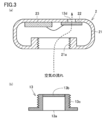
- FIG. (A) is a top view
- (b) is a sectional view. It is a figure showing roughly the composition of the suction system of Embodiment 1.
- (A) is a top view
- (b) is a sectional view.
- (A) is a cross-sectional enlarged view schematically showing the configuration of the suction module.
- (B) is a cross-sectional enlarged view schematically showing the configuration of the connecting member.
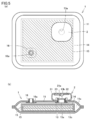
- FIG. (A) is a top view
- (b) is a sectional view.
- (A) is a schematic diagram which shows an example of a cuffed tracheal tube.
- (B) is a schematic diagram showing an enlarged AA cross section of the tracheal tube shown in (a).
- (C) is a schematic diagram which shows a mode that the tracheal tube was inserted in the trachea from the oral cavity. It is sectional drawing which shows the structure of the piezoelectric pump used for the suction system of Embodiment 1. It is a figure which shows schematically the structure of a modification about the drainage bag of Embodiment 1.
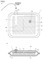
- FIG. (A) is a top view
- (b) is a sectional view.
- FIG. (A) is a top view
- (b) is a sectional view. It is sectional drawing which shows schematically the structure of a modification about the drainage bag of Embodiment 2.
- FIG. (A) is a top view
- (b) is a sectional view. It is sectional drawing which shows schematically the structure of a modification about the drainage bag of Embodiment 2.
- the drainage bag 1 includes a flexible container 11, a water absorbing material 15, and a filter 14. Drained liquid (suctioned secretion etc.) is stored in the interior 11 a of the flexible container 11 while being held by the water absorbing material 15.
- the material of the flexible container 11 is not particularly limited, but is formed of a flexible material that can reduce (crush) the volume of the interior 11a before use.
- a material for the flexible container for example, polyethylene, polypropylene, or the like can be used.
- the drainage bag before use (before absorbing the drainage) is thin and almost flat, so when storing a large number of drainage bags before use, the storage space can be greatly reduced. Can do.
- the initial internal volume of the container is small, there are also advantages that the time required for the inside of the container to become negative pressure is short and the power consumption is small.
- the shape of the flexible container 11 is not particularly limited, for example, it is a bag-shaped container as shown in FIG.
- the bag-like flexible container 11 can be produced, for example, by thermally welding the peripheral portions of two flexible sheets. Since the drainage bag of the present embodiment has a simple structure mainly composed of a flexible container 11 such as a bag and a water absorbing material, it can be manufactured at a relatively low cost and is easily disposable.
- the flexible container 11 has an inflow port (first opening) 12b and an exhaust port (second opening) 13a.
- the tube 12 having the suction port 12a and the inflow port 12b is arranged in a state of being sandwiched between two sheets.
- the tube 12 can be arranged in this way by welding simultaneously when sheets are welded together.
- suction port 12a One end (suction port 12a) of the tube 12 communicates with the suction tube connecting portion 87 of the tracheal tube with a cuff upper suction lumen as shown in FIG. 6 (a) outside the flexible container 11.
- the other end (inflow port 12 b) of the tube 12 communicates with the inside 11 a of the flexible container 11. Thereby, it is possible to allow the biological drainage fluid to flow toward the inside 11 a of the flexible container 11 through the tube 12.
- a material of the tube 12 for example, polyvinyl chloride, polypropylene, or the like can be used as a material of the tube 12.
- the exhaust port 13 a is provided on one side (one sheet) of the flexible container 11.
- the exhaust port 13a is provided with a hydrophobic filter 13b so as to block the air flow path passing through the exhaust port 13a (so as to cover the exhaust port 13a). That is, the exhaust port 13a communicates with the suction device via the hydrophobic filter 13b.
- the hydrophobic filter 13b By providing the hydrophobic filter 13b, it is possible to suppress or prevent the intrusion of the drained liquid into the suction device. Thereby, it can prevent that a suction device fails.
- the exhaust port 13a is not limited to such an aspect, and as shown in FIG. 9, the tube 13d having the exhaust port 13a includes two sheets constituting the flexible container 11 as in the tube 12. You may arrange
- At least one sheet-like water absorbing material 15 is disposed in the interior 11a of the flexible container 11.
- two water absorbing materials 15 are arranged in FIG. 2, two water absorbing materials 15 are arranged.
- the water absorbing material 15 preferably contains a water absorbing polymer.
- the water absorbing material 15 preferably includes a holding member, and the water absorbing polymer is preferably held by a holding member (preferably a fiber material or a plate-like member).
- the water-absorbing polymer is a polymer designed to have a high water retention performance and is also called a high water-absorbing polymer (SAP).
- SAP high water-absorbing polymer
- known synthetic polymers having a water-absorbing property polymers derived from natural products, and the like can be used.
- Examples of the synthetic polymer having water absorption include polyacrylic acid resins, polyethylene oxide resins, maleic anhydride resins, polysulfonic acid resins, polyacrylamide resins, polyvinyl alcohol resins, or combinations thereof. It is done.
- polymers derived from natural products having water absorption include polyaspartic acid-based, polyglutamic acid-based, polyalginic acid-based, starch-based, cellulose-based, pullulan-based, dextran-based, dextrin-based, and other polysaccharide cross-linked products, or those Combinations are listed.
- the average particle diameter (number average particle diameter) of the water-absorbing polymer is, for example, 0.1 mm to 4 mm.
- the water absorbing material 15 may include various thickening materials such as thickening polysaccharides, clay minerals such as montmorillonite, or the like, instead of the above water absorbing polymer.
- the holding member is made of, for example, a fiber material such as pulp, and the water-absorbing polymer is held in a state where the water-absorbing polymer is randomly distributed in the gaps between the fiber materials.
- the holding member may be a plate-like member made of, for example, paper or plastic, and is not particularly limited as long as the member can hold the water-absorbing polymer.
- the drainage container When the drainage liquid leaks from the drainage container, there is a concern about an increase in infectious diseases. Therefore, it is preferable that the drainage container is difficult to leak the liquid. Conventionally, hard resin materials that are not easily damaged have been used from such a viewpoint.
- the drainage bag of the present embodiment includes a water absorbing material, so that the drained liquid is held by the water absorbing material and is externally provided. Therefore, even if a soft resin material or the like is used as the material of the container, there is an advantage that the drainage is difficult to leak. Thereby, the infectious disease by exposure of bacteria or a virus can be suppressed.
- the water-absorbing polymer has a feature that the volume before water absorption is small and the volume expands by absorbing water. Thus, since the water-absorbing polymer expands itself by absorbing water, it is not necessary to manually inflate the container before use, and suction can be started quickly and easily when necessary.
- the filter 14 may be a member that allows liquid such as drainage to pass therethrough but does not allow water-absorbing polymer particles to pass therethrough, and may pass substances other than water (liquid and solid).
- the shape of the filter 14 is not specifically limited, For example, it is a film
- water-absorbing paper, cloth material, non-woven fabric, absorbent cotton, a plastic sheet having many fine holes, or the like can be used.
- the filter 14 is disposed between the inlet 12b and the water absorbing material 15, and is seen in a plan view (for example, a plan view seen from the thickness direction of the drainage bag, a plan view seen from the suction direction, or a flow
- a plan view for example, a plan view seen from the thickness direction of the drainage bag, a plan view seen from the suction direction, or a flow
- the inlet 12b and the water absorbing material 15 are arranged so as to include an overlapping portion.
- the filter 14 is disposed between the exhaust port 13a and the water absorbing material 15, and is seen in a plan view (for example, a plan view seen from the thickness direction of the drainage bag, a plan view seen from the exhaust direction, or an exhaust gas).
- the exhaust port 13a and the water absorbing material 15 are arranged so as to include a portion overlapping in the plane view as viewed from the direction parallel to the shortest line segment connecting the center of gravity of the port 13a and the water absorbing material 15.
- the filter 14 disposed between the inlet 12b and the water absorbing material 15 and the filter 14 disposed between the exhaust port 13a and the water absorbing material 15 are different filters as shown in FIG. There may be one filter connected as shown in FIG.
- the water-absorbing material 15 is generally free to move by separating from the holding member in the process of absorbing water and expanding.
- the inside 11a of the flexible container 11 becomes negative pressure due to suction and the flexible container 11 is compressed, the water-absorbing polymer released from the holding member by the pressing force is absorbed into the inflow port 12b and the exhaust port 13a.
- the inflow port 12b and the exhaust port 13a are blocked and the suction cannot be continued.
- the present inventors arrange the filter 14 between the inlet 12b and the water absorbent 15 and between the exhaust port 13a and the water absorbent 15 as described above. It has been found that the filter 14 blocks the inflow of the water-absorbing polymer to the inlet 12b and the exhaust port 13a, thereby preventing the inlet 12b and the exhaust port 13a from being blocked.
- the filter 14 covers the water absorbing material 15 in a large area, and the inlet 12b of the tube 12 is disposed at a position overlapping the water absorbing material through the filter 14 when viewed in plan (for example, the filter 14 Due to the capillary phenomenon or the like, the drainage liquid spreads substantially radially from the inlet 12b, and can spread efficiently and quickly over the entire water-absorbing material 15.
- the hydrophobic filter is a filter that allows gas such as air to pass through without allowing liquid such as drainage to pass through.
- the material of the hydrophobic filter is not particularly limited as long as it is a hydrophobic material, and examples thereof include polytetrafluoroethylene.
- suction system including the same drain bag as described above.
- the suction system of this embodiment is used, for example, to continuously suck secretions such as saliva accumulated in the upper part of the cuff of the tracheal tube or in the oral cavity.
- the suction system of this embodiment is not restricted to the use at the time of such tracheal intubation, but can be applied to various uses such as other medical use and oral care use.
- the suction system mainly includes a suction module 2 that generates suction pressure and a drainage bag 1 for storing drainage (suctioned secretions and the like) (see FIG. 2).
- a suction module 2 that generates suction pressure
- a drainage bag 1 for storing drainage (suctioned secretions and the like) (see FIG. 2).
- FIG. 6C is a schematic diagram showing a state in which the tracheal tube 81 is inserted into the trachea 91 from the oral cavity 94.
- a tracheal tube (tracheal intubation tube, endotracheal tube) 8 is inserted from the oral cavity 94 of the subject into the trachea 91.
- secretions such as saliva flow into the trachea 91 from the gap between the inserted tracheal tube 81 and the inner wall 91a of the trachea 91, and the subject is May cause ventilator-associated pneumonia (VAP).
- VAP ventilator-associated pneumonia
- a cuff 7 is provided at a predetermined position on the outer periphery of the tracheal tube 81.
- the cuff 7 can be expanded by supplying air from the outside.
- a cuffed tracheal tube it is possible to prevent inflow of secretions and the like into the trachea 91 by the cuff 7 while securing an airway by the tracheal tube 81.
- secretions accumulated in the upper part (oral cavity 94 side) of the cuff 7 may gradually leak into the airway in the lower part of the cuff 7 through a slight gap between the inner wall 91a of the trachea 91 and the cuff 7 over time. Therefore, in order to prevent ventilator-associated pneumonia (VAP) more completely, it is said that it is effective to continuously suck and remove secretions accumulated in the upper part of the cuff 7 or the like.
- VAP ventilator-associated pneumonia
- a tracheal tube with a cuff (a cuff upper suction lumen) provided with a hole 86a for secretion secretion near the upper portion of the cuff 7 of the tracheal tube 81 is provided.
- An attached tracheal tube is commercially available (see FIG. 6A).
- a suction channel 86 and a cuff channel 88a formed in parallel with the main channel 81a are provided in the wall portion constituting the main channel 81a of the tracheal tube 81. (See FIG. 6B).
- the suction flow path 86 communicates with a hole 86 a that opens to the outside of the tracheal tube 81 in the vicinity of the cuff 7, and on the other hand, communicates with the suction pipe connection portion 87.
- a cuff channel 88a is also provided in the wall of the tracheal tube 81 (FIG. 6B).
- the cuff channel 88 a communicates with the inside of the cuff 7 on the outer peripheral side of the tracheal tube 81 on the one hand and communicates with the cuff expansion tube 88 on the other hand.
- the cuff can be expanded by sending air or the like to the cuff 7 through the cuff expansion pipe 88 and the cuff flow path 88a.
- the cuff channel 88a is not shown for simplification.
- the suction system of the present embodiment is connected to a suction pipe connecting portion 87 of a cuffed tracheal tube (a tracheal tube with a cuff upper suction lumen) 8 as shown in FIG. Used in state.
- a suction pipe connecting portion 87 of a cuffed tracheal tube a tracheal tube with a cuff upper suction lumen 8 as shown in FIG. Used in state.
- the other end of the connection tube is connected to, for example, the suction port 12a of the suction system (see FIG. 2A).
- the suction system of this embodiment includes a drainage bag 1 and a suction module 2.
- the drainage bag 1 is basically the same as the drainage bag described with reference to FIG. 1, except that the connection member 13 is provided at the exhaust port 13a.
- the drainage bag 1 and the suction module 2 are connected by the connecting member 13. Thereby, the exhaust port 13 a communicates with the inside of the suction module 2.
- the connecting member 13 preferably has a space communicating with the exhaust port 13a between the lower surface of the connecting member 13 and the upper surface of the connecting member 13 provided with the hydrophobic filter 13b.
- the connecting member 13 is preferably made of a hard material such as polyethylene, polypropylene, or ABS resin.
- the connecting member is formed so as not to leak air or liquid by being thermally welded to a sheet around the exhaust port.
- a small suction module 2 is used as a suction device connected to the drainage bag 1 as shown in FIG. 2
- suction is performed.
- another suction device such as a large suction device (for example, a medical low-pressure suction / discharge device disclosed in Patent Document 1) widely used in medical institutions may be used.
- the suction module 2 mainly includes a casing 21 having a discharge port 13d, a suction pump 22, and a control unit (control circuit, drive circuit) 23 electrically connected thereto. .
- a control unit control circuit, drive circuit 23 electrically connected thereto.
- air is sent from the exhaust port 13 a to the discharge port 13 d (in the direction of the dotted arrow in the figure), and the inside 11 a of the flexible container 11 of the drainage bag 1. The air can be sucked.
- a screw groove 21a is provided on the inner peripheral wall of the exhaust port 13a of the casing 21 constituting the suction module 2 (FIG. 3A), and the outer periphery of the connection member 13 included in the drainage bag 1 is provided.
- a screw groove 13c is provided on the wall.
- the suction module 2 can be detached from the drainage bag 1. Therefore, if the suction module 2 is removed from the drainage bag 1 and only the drainage bag 1 is discarded, the suction module 2 can be used repeatedly.
- the exhaust port 13a is provided with a hydrophobic filter 13b so as to block the air flow path passing through the exhaust port 13a (so as to cover the exhaust port 13a). That is, the exhaust port 13a communicates with the inside of the suction module 2 through the hydrophobic filter 13b.
- the hydrophobic filter 13b By providing the hydrophobic filter 13b, the intrusion of the drained liquid into the suction module 2 can be suppressed. Thereby, it can prevent that the suction module 2 fails.
- the suction module 2 preferably includes a suction pump 22.
- the suction pump include a piezoelectric pump and a motor pump.
- the suction pump 22 is preferably a piezoelectric pump. Referring to FIG. 7, in piezoelectric pump 22a, piezoelectric element 200 made of, for example, lead zirconate titanate (PZT) ceramics is bonded to metal diaphragm 201. A metal plate 202b provided with a discharge hole 202a at the center is bonded to the diaphragm 201 with a spacer 202c interposed therebetween so as to form a pump chamber 202.
- PZT lead zirconate titanate
- the piezoelectric element 200 When the piezoelectric element 200 is resonated by applying a voltage, the diaphragm 201 is flexibly vibrated, and a volume change occurs in the pump chamber 202. As a result, a high-speed air flow is intermittently generated in the discharge hole 202a. At this time, since the pressure decreases in the vicinity of the discharge hole 202a, air in the suction flow path 203 is sucked in the direction of the discharge hole 202a, and as a result, air is discharged from the nozzle 204. Thus, the piezoelectric pump 22a acts as an air pump that sucks air from the lower side and discharges it to the upper side, as indicated by arrows in FIG.
- the piezoelectric pump 22a has a feature that when the voltage (power) supply is stopped and the bending vibration of the piezoelectric element 200 is stopped, the suction can be stopped immediately. Therefore, the piezoelectric pump 22a can easily perform intermittent drive control.
- the suction module 2 can be reduced in size or thickness by using the piezoelectric pump 22a.
- the piezoelectric pump is lightweight, the suction module 2 can be reduced in weight.
- the apparatus main body including the electric pump is larger than the drainage container and is heavy, so that it is difficult to move and there are many restrictions on the installation place.
- the suction module 2 that is a suction device using a piezoelectric pump is small and light (smaller than the drainage container), so it is easy to move and is installed and used in various places in the medical field. It is possible.
- the control unit 23 can control the driving of the piezoelectric pump 22a, and is composed of, for example, a memory control unit (MCU). In this embodiment, the control part 23 can drive the piezoelectric pump 22a intermittently.
- MCU memory control unit
- the piezoelectric pump 22a by intermittently driving the piezoelectric pump 22a, it is possible to prevent the tip of the suction tube from being adsorbed to the tracheal mucosa or the oral mucosa during suction. Thereby, the risk of mucosal damage caused by such an adsorption state can be avoided, and the safety of the suction system can be improved. Further, by intermittently driving the piezoelectric pump 22a, the power consumption of the suction system can be saved, and a long-time use becomes possible.
- the suction time for one time is desirably a time sufficient to finish sucking most of the secretions in the upper part of the cuff, but more than necessary to reduce power consumption. It is preferable not to lengthen the suction time.
- the suction interval is preferably shorter than a predetermined time so that secretions in the upper part of the cuff do not accumulate and the risk of VAP increases. On the other hand, in order to reduce power consumption, it is preferable not to make the suction interval too short. What is necessary is just to set the specific 1 time of suction and the space
- the suction module 2 may further include a power source, an operation switch, a display unit, and the like (not shown).
- the power source is electrically connected to each unit (piezoelectric pump 22a, control unit 23) of the suction module 2 so that power (voltage) can be supplied. As a result, the suction module 2 can be driven without requiring an external power source.
- the suction module 2 may have a pressure sensor for detecting the suction pressure.
- the suction system of the present embodiment may further include a tracheal tube (a tracheal tube with a cuff upper suction lumen) as shown in FIG. 6A having a cuff and a suction channel.
- a tracheal tube a tracheal tube with a cuff upper suction lumen
- the drainage bag and the suction system of the present embodiment are formed so that the filter wraps not only on one side of the sheet-like water absorbent but also on the entire water absorbent 15 including both sides and sides. This is different from the first embodiment. Other points are the same as in the first embodiment.
- the suction port (tube 12) and the water absorbing material 15 may be arrange
- the inlet 12b and the exhaust port 13a are basically not closed by the expanded water-absorbing polymer.
- the inlet 12b and the exhaust port 13a are basically not closed by the expanded water-absorbing polymer.
- the inlet 12b and the exhaust port 13a have a predetermined distance from the end of the filter in plan view. It is preferable to place them.
- the tube 12 separates the inlet 12b from the end of the filter.
- there is no such restriction and the layout design is easy.
- the tube 12 may not be provided. Therefore, as shown in FIG. 5, the inflow port 16a has a hole penetrating in the thickness direction of the drainage bag. 16 may be formed.
- the connection tube connected to the suction pipe connection portion 87 of the cuffed tracheal tube 8 is inserted into the connection port 16 of the drainage bag 1 shown in FIG. 5 toward the inside 11 a of the flexible container 11.
- the inserted connection tube may be connected to the connection port by a fixing means, and may not be particularly connected.
- the inflow port 12b can be arranged at an arbitrary position on the surface of the flexible container 11, but in order to effectively use the entire water absorbing material for absorbing the drainage, the exhaust port 13a. It is preferable to arrange at a position distant from.
- 1 drain bag 11 flexible container, 11a inside, 12 tube, 12a suction port, 12b inlet, 13 connecting member, 13a exhaust port, 13b hydrophobic filter, 13c thread groove, 13d tube, 14 filter, 15 water absorption Material, 16 connection port, 16a inlet, 2, suction module, 21 housing, 21a screw groove, 22 suction pump, 22a piezoelectric pump, 23 control unit, 200 piezoelectric element, 201 diaphragm, 202 pump chamber, 202a discharge hole, 202b Metal plate, 203 suction channel, 204 nozzle, 7 cuff, 8 cuffed tracheal tube (tracheal tube with cuff upper suction lumen), 81 tracheal tube, 81a main channel, 86 suction channel, 86a hole, 87 suction tube connection 88 cuff expansion tube, 88a Full passage, 91 trachea, 91a inner wall 92 esophagus, 93 epiglottis 94 oral.
Landscapes
- Health & Medical Sciences (AREA)
- Heart & Thoracic Surgery (AREA)
- Vascular Medicine (AREA)
- Engineering & Computer Science (AREA)
- Anesthesiology (AREA)
- Biomedical Technology (AREA)
- Hematology (AREA)
- Life Sciences & Earth Sciences (AREA)
- Animal Behavior & Ethology (AREA)
- General Health & Medical Sciences (AREA)
- Public Health (AREA)
- Veterinary Medicine (AREA)
- External Artificial Organs (AREA)
Abstract
流入口および排気口を有する可撓性容器と、可撓性容器の内部に収納された吸水材およびフィルタと、を備える排液バックであって、フィルタは、平面視において、流入口と排気口との間に配置されていることを特徴とする、排液バッグ。
Description
本発明は、排液バッグおよび吸引システムに関する。
人工呼吸中のガスリークの防止と誤嚥防止のために、「カフ付きの気管チューブ」を使用することがある。また、このカフの上部に貯留する分泌物を吸引するために、吸引管(吸引ルーメン)を有する「カフ上部吸引ルーメン付き気管チューブ」を使用する場合がある。
ここで、吸引管に接続する専用の吸引器はなく、医療機関で用いられる汎用の低圧持続吸引器(例えば、特許文献1(特開平11-226115号公報)に開示される医療用低圧吸引排出装置)が使用されている。この低圧持続吸引器の主な構成要素は、排液を溜める容器(主に硬質のプラスチック材料などの成型品)、陰圧を発生させる電動ポンプ、および、それらを接続する複数の接続部である。
なお、軟質のプラスチック材料などからなる可撓性の収納容器として、例えば、特許文献2(特開2013-169414号公報)には、排液を吸収してゲル化する排液吸収材を備える収納容器が開示されている。ただし、この収納容器は、可撓性容器の内部に生体排液を流入させるための流入口(導入口)のみを有するものであり、尿などの体内から自ら排出される生体排液の回収に使用されるものである。この収納容器は、吸引口を有していないため、吸引装置に接続することができず、カフ上部に溜まる分泌物などの自ら排出されない生体排液を吸引するために用いることはできない。
上述のような低圧持続吸引器に用いられる排液容器は、ポンプによって生じる陰圧で潰れないように、硬質の材料で成形される。また、幅広い用途に使用できるように、通常は大きな容積を有している。さらに、そして、排液容器は、繰り返し使用すると雑菌の繁殖による悪臭などの衛生面の問題が生じるため、一般的にはディスポーザブルなものであり、一回の使用毎に廃棄される。
したがって、このような硬質材料で成形された、大きな容積を有する排液容器を、医療現場において多数在庫しておく必要があり、多くの保管スペースが必要となるという問題があった。
本発明は、上記の課題に鑑み、保管スペースを削減することのできる排液容器(排液バッグ)を提供することを目的とする。
[1]
流入口および排気口を有する可撓性容器と、
吸水材と、
前記吸水材を透過させないフィルタと、
を備える排液バックであって、
前記吸水材および前記フィルタは、前記可撓性容器の内部に収納されており、
前記フィルタは、平面視において、前記流入口と前記排気口との間に配置されていることを特徴とする、排液バッグ。
[2]
平面視において、前記流入口と前記吸水材とが重なるように配置され、
前記フィルタは、前記流入口と前記吸水材との間に配置され、かつ、平面視において、前記流入口と前記吸水材とが重なる部分を含むように配置されている、[1]に記載の排液バッグ。
[3]
平面視において、前記排気口と前記吸水材とが重なるように配置され、
前記フィルタは、前記排気口と前記吸水材との間にも配置され、かつ、平面視において前記排気口と前記吸水材とが重なる部分を含むように配置されている、[1]または[2]に記載の排液バッグ。
[4]
前記吸水材は吸水性ポリマーを含む、[1]~[3]のいずれかに記載の排液バッグ。
[5]
前記吸水材は、保持部材を含み、前記吸水性ポリマーは前記保持部材に保持されている、[4]に記載の排液バッグ。
[6]
前記排気口を覆う疎水性フィルタをさらに備える、[1]~[5]のいずれかに記載の排液バッグ。
[7]
前記排気口を吸引装置に接続するため接続部材が前記排気口に設けられており、
前記接続部材は、前記排気口に連通する空間を有している、[1]~[6]のいずれかに記載の排液バッグ。
[8]
前記接続部材が前記排気口を覆う疎水性フィルタを有している、[7]に記載の排液バッグ。
[9]
前記吸水材の全体が前記フィルタで包まれている、[1]~[8]のいずれかに記載の排液バッグ。
[10]
[1]~[9]のいずれかに記載の排液バッグと、
前記排液バッグの前記排気口に接続された、吸引ポンプを有する吸引モジュールと、
を備える吸引システム。
[11]
前記吸引ポンプは圧電ポンプである、[10]に記載の吸引システム。
[12]
前記吸引モジュールは、前記吸引ポンプを間欠的に駆動させるように制御可能な制御部を備える、[10]または[11]に記載の吸引システム。
[13]
さらに、カフと吸引用流路とを有する気管チューブを備える、[10]~[12]のいずれかに記載の吸引システム。
流入口および排気口を有する可撓性容器と、
吸水材と、
前記吸水材を透過させないフィルタと、
を備える排液バックであって、
前記吸水材および前記フィルタは、前記可撓性容器の内部に収納されており、
前記フィルタは、平面視において、前記流入口と前記排気口との間に配置されていることを特徴とする、排液バッグ。
[2]
平面視において、前記流入口と前記吸水材とが重なるように配置され、
前記フィルタは、前記流入口と前記吸水材との間に配置され、かつ、平面視において、前記流入口と前記吸水材とが重なる部分を含むように配置されている、[1]に記載の排液バッグ。
[3]
平面視において、前記排気口と前記吸水材とが重なるように配置され、
前記フィルタは、前記排気口と前記吸水材との間にも配置され、かつ、平面視において前記排気口と前記吸水材とが重なる部分を含むように配置されている、[1]または[2]に記載の排液バッグ。
[4]
前記吸水材は吸水性ポリマーを含む、[1]~[3]のいずれかに記載の排液バッグ。
[5]
前記吸水材は、保持部材を含み、前記吸水性ポリマーは前記保持部材に保持されている、[4]に記載の排液バッグ。
[6]
前記排気口を覆う疎水性フィルタをさらに備える、[1]~[5]のいずれかに記載の排液バッグ。
[7]
前記排気口を吸引装置に接続するため接続部材が前記排気口に設けられており、
前記接続部材は、前記排気口に連通する空間を有している、[1]~[6]のいずれかに記載の排液バッグ。
[8]
前記接続部材が前記排気口を覆う疎水性フィルタを有している、[7]に記載の排液バッグ。
[9]
前記吸水材の全体が前記フィルタで包まれている、[1]~[8]のいずれかに記載の排液バッグ。
[10]
[1]~[9]のいずれかに記載の排液バッグと、
前記排液バッグの前記排気口に接続された、吸引ポンプを有する吸引モジュールと、
を備える吸引システム。
[11]
前記吸引ポンプは圧電ポンプである、[10]に記載の吸引システム。
[12]
前記吸引モジュールは、前記吸引ポンプを間欠的に駆動させるように制御可能な制御部を備える、[10]または[11]に記載の吸引システム。
[13]
さらに、カフと吸引用流路とを有する気管チューブを備える、[10]~[12]のいずれかに記載の吸引システム。
本発明によれば、保管スペースを削減することのできる排液容器(排液バッグ)を提供することができる。
以下、本発明の実施形態について、図面を参照して説明する。なお、図面において、同一の参照符号は、同一部分または相当部分を表すものである。また、長さ、幅、厚さ、深さなどの寸法関係は図面の明瞭化と簡略化のために適宜変更されており、実際の寸法関係を表すものではない。なお、実施形態は例示であり、異なる形態で示した構成の部分的な置換または組み合わせが可能であることは言うまでもない。
[実施形態1]
<排液バッグ>
以下、本実施形態の排液バッグ1の構成について説明する。
<排液バッグ>
以下、本実施形態の排液バッグ1の構成について説明する。
図1を参照して、排液バッグ1は、可撓性容器11と、吸水材15と、フィルタ14とを備える。排液(吸引した分泌物等)は、可撓性容器11の内部11aに、吸水材15に保持された状態で貯留される。
可撓性容器11の材質は、特に限定されないが、使用前に内部11aの体積を小さくする(押し潰す)ことができような可撓性を有する材料から形成される。可撓性容器の材料としては、例えば、ポリエチレン、ポリプロピレンなどを使用できる。このように、使用前(排液を吸水する前)の排液バッグは、厚みが薄くほぼ平らになるため、使用前の排液バッグを多数保管する際に、保管スペースを大幅に削減することができる。また、初期の容器内容積が小さいため、容器内が陰圧になるまでに要する時間が短く、また、消費電力も少ないという利点もある。
可撓性容器11の形状も特に限定されないが、例えば図2に示されるような袋状の容器である。袋状の可撓性容器11は、例えば、2枚の柔軟なシートの周縁部を熱溶着するなどして作製することができる。本実施形態の排液バッグは、主に袋状などの可撓性容器11と吸水材とから構成されるシンプルな構造を有しているため、比較的安価で製造でき、使い捨てにし易い。
可撓性容器11は、流入口(第一開口部)12bと排気口(第二開口部)13aとを有している。
本実施形態においては、図2に示されるように、吸引口12aおよび流入口12bを有するチューブ12が、2枚のシートに挟まれた状態で配置されている。チューブ12は、シート同士を溶着する際に同時に溶着することで、このように配置することができる。
チューブ12の一端(吸引口12a)は、可撓性容器11の外部において図6(a)に示されるようなカフ上部吸引ルーメン付き気管チューブの吸引管接続部87に連通する。チューブ12の他端(流入口12b)は、可撓性容器11の内部11aに連通している。これにより、チューブ12を介して、可撓性容器11の内部11aに向けて、生体排液を流入させることが可能となっている。なお、チューブ12の材質としては、例えば、ポリ塩化ビニル、ポリプロピレンなどを使用することが出来る。
排気口13aは、可撓性容器11の片面(一方のシート)に設けられている。また、排気口13aには、排気口13aを通る空気の流路を塞ぐように(排気口13aを覆うように)、疎水性フィルタ13bが設けられている。すなわち、排気口13aは、疎水性フィルタ13bを介して吸引装置に連通する。疎水性フィルタ13bを設けることで、吸引装置内への排液の侵入を抑制または防止することができる。これにより、吸引装置が故障することを防止できる。
なお、排気口13aはこのような態様に限定されず、図9に示されるように、チューブ12と同様に、排気口13aを有するチューブ13dが、可撓性容器11を構成する2枚のシートに挟まれた状態で配置されていてもよい。
可撓性容器11の内部11aには、シート状の吸水材15が少なくとも1枚配置されている。なお、図2においては、2枚の吸水材15が配置されている。
吸水材15は、吸水性ポリマーを含むことが好ましい。また、吸水材15は、保持部材を含み、吸水性ポリマーが保持部材(好ましくは繊維素材。板状部材でもよい。)に保持されていることが好ましい。
吸水性ポリマーは、高い水分保持性能を有するように設計された高分子であり、高吸水性高分子(SAP)とも呼ばれる。吸水性ポリマーとしては、吸水性を有する公知の合成ポリマー、天然物由来ポリマーなどを用いることができる。吸水性を有する合成ポリマーとしては、例えば、ポリアクリル酸系樹脂、ポリエチレンオキシド系樹脂、無水マレイン酸系樹脂、ポリスルホン酸系樹脂、ポリアクリルアミド系樹脂、ポリビニルアルコール系樹脂、または、それらの組み合わせが挙げられる。吸水性を有する天然物由来ポリマーとしては、ポリアスパラギン酸系、ポリグルタミン酸系、ポリアルギン酸系、デンプン系、セルロース系、プルラン系、デキストラン系、デキストリン系、その他多糖類の架橋物、または、それらの組み合わせが挙げられる。吸水性ポリマーの平均粒子径(数平均粒子径)は、例えば0.1mm~4mmである。
なお、吸水材15は、上記の吸水性ポリマーに代えて、あるいは、上記の吸水性ポリマーと共に、増粘多糖類等の各種増粘材、モンモリロナイト等の粘土鉱物などを含んでいてもよい。
保持部材は、例えば、パルプなどの繊維素材から成り、吸水性ポリマーがその繊維素材の隙間にランダムに分散配置された状態で保持されている。なお、保持部材は、例えば、紙、プラスチックなどからなる板状の部材であってもよく、吸水性ポリマーを保持できる部材であれば特に限定されない。
排液容器から排液が漏れると、感染症の増加が懸念されるため、排液容器は液が漏れ難いものであることが好ましい。従来は、このような観点から、破損し難い硬質の樹脂材料等が用いられていたが、本実施形態の排液バッグは、吸水材を備えることにより、排液が吸水材に保持されて外部に漏れにくくなるため、容器の材質として軟質の樹脂材料等を使用しても排液が漏れ難いという利点も有している。これにより、細菌やウイルスの曝露による感染症を抑制することができる。
また、吸水性ポリマーは、吸水前の体積は小さく、吸水することで体積が膨張するという特徴を有している。このように、吸水性ポリマーは、吸水することで自ら膨張するため、使用前に用手で容器を膨らませておく必要はなく、必要な時に簡単に素早く吸引を開始することができる。
フィルタ14は、排液などの液体を通すが、吸水性ポリマーの粒子を通さない部材であればよく、水以外の物質(液体および固体)を通すものであってもよい。フィルタ14の形状は、特に限定されないが、例えば膜状である。フィルタ14としては、具体的には、吸水紙、布材、不織布、脱脂綿、多数の微細な穴を持つプラスチックのシートなどを使用できる。
フィルタ14は、流入口12bと吸水材15との間に配置されており、かつ、平面視(例えば、排液バッグの厚み方向から見た平面視、吸引方向から見た平面視、または、流入口12bの重心と吸水材15とを結ぶ最短の線分と平行な方向から見た平面視)において、流入口12bと吸水材15とが重なる部分を含むように配置されている。
また、フィルタ14は、排気口13aと吸水材15との間に配置され、かつ、平面視(例えば、排液バッグの厚み方向から見た平面視、排気方向から見た平面視、または、排気口13aの重心と吸水材15とを結ぶ最短の線分と平行な方向から見た平面視)において排気口13aと吸水材15とが重なる部分を含むように配置されている。
なお、流入口12bと吸水材15との間に配置されるフィルタ14と、排気口13aと吸水材15との間に配置されるフィルタ14とは、図8に示されるように別のフィルタであってもよく、図1に示されるように繋がった1枚のフィルタであってもよい。
吸水材15は、一般に、吸水して膨張する過程で、保持部材から離脱して自由に動けるようになる。この場合、吸引により可撓性容器11の内部11aが陰圧になり、可撓性容器11が圧縮されると、その押圧力により保持部材から離脱した吸水性ポリマーが流入口12bおよび排気口13aに押し込まれて、流入口12bおよび排気口13aを塞いでしまい、吸引を継続できなくなることが、本発明者らの検討により判明した。
本発明者らは、かかる知見に基づいて、上記のように、流入口12bと吸水材15との間、および、排気口13aと吸水材15との間に、フィルタ14を配置することで、フィルタ14が流入口12bおよび排気口13aへの吸水性ポリマーの流入を遮断するため、流入口12bおよび排気口13aの閉塞を防止できることを見出した。
また、フィルタ14が広い面積で吸水材15を覆い、かつ、チューブ12の流入口12bが平面視した時にフィルタ14を介して吸水材と重なる位置に配置されることにより、(例えば、フィルタ14の毛細管現象などによって、)排液が流入口12bから略放射状に広がり、吸水材15全体に対して、効率よく素早く広がることが出来る。
なお、疎水性フィルターとは、排液などの液体を透過させず、空気などの気体を通過させることが可能なフィルターである。疎水性フィルターの材質としては、疎水性の材質であれば特に限定されないが、例えば、ポリテトラフルオロエチレンなどが挙げられる。
<吸引システム>
次に、上記と同様の排液バッグを備える吸引システムについて説明する。本実施形態の吸引システムは、例えば、気管チューブのカフ上部や口腔内に溜まった唾液等の分泌物を持続的に吸引するために用いられる。なお、本実施形態の吸引システムは、このような気管挿管時の用途だけに限られず、その他の医療用、口腔ケア用などの種々の用途に適用することができる。
次に、上記と同様の排液バッグを備える吸引システムについて説明する。本実施形態の吸引システムは、例えば、気管チューブのカフ上部や口腔内に溜まった唾液等の分泌物を持続的に吸引するために用いられる。なお、本実施形態の吸引システムは、このような気管挿管時の用途だけに限られず、その他の医療用、口腔ケア用などの種々の用途に適用することができる。
吸引システムは、主に、吸引圧を発生させる吸引モジュール2と、排液(吸引した分泌物等)を貯留するための排液バッグ1とを備える(図2参照)。まず、吸引システムの詳細を説明する前に、本実施形態の吸引システムの使用形態について説明する。
図6(c)は、気管チューブ81が口腔94から気管91内に挿入された様子を示す模式図である。人工呼吸器の使用時に気管挿管で気道を確保する場合、被検体の口腔94から気管91へ気管チューブ(気管挿管チューブ、気管内チューブ)8を挿入する。このとき、喉頭蓋93は常に開かれた状態となるため、挿入された気管チューブ81と気管91の内壁91aとの間の隙間から、気管91内に唾液等の分泌物が流入し、被検体が人工呼吸器関連肺炎(VAP)を発症するおそれがある。
このような分泌物の流入を防止するため、気管チューブ81の外周の所定の位置にカフ7が設けられている。このカフ7は、外部からの空気の供給によって膨張させることができる。カフ7を膨張させることにより、カフ7の外周面が気管91の内壁91aに接触して気管チューブ81と気管91の内壁91aとの隙間が閉塞される。このようなカフ付き気管チューブを用いることで、気管チューブ81により気道を確保しつつ、カフ7により気管91への分泌物等の流入を防止することができる。
ただし、カフ7の上部(口腔94側)に溜まった分泌物は、時間とともに気管91の内壁91aとカフ7の僅かな隙間から、カフ7の下部の気道に少しずつ漏れてしまう虞がある。したがって、人工呼吸器関連肺炎(VAP)をより完全に予防するためには、カフ7の上部などに溜った分泌物を持続的に吸引し、除去することが有効であると言われている。
このような分泌物の吸引を容易に行うことを可能とするために、気管チューブ81のカフ7の上部付近に分泌物の吸引用の孔86aが設けられたカフ付き気管チューブ(カフ上部吸引ルーメン付き気管チューブ)が市販されている(図6(a)参照)。
図6(a)に示すカフ付き気管チューブにおいて、気管チューブ81の主流路81aを構成する壁部内には、主流路81aと並列して形成された吸引流路86およびカフ用流路88aが設けられている(図6(b)参照)。吸引流路86は、一方で、カフ7の近傍において気管チューブ81の外側に開口した孔86aに連通し、他方で、吸引管接続部87に連通している。このような構成により、吸引管接続部87を吸引システムに接続して吸引を行うことで、カフ7の上部付近に溜まった分泌物等を吸引することができる。
なお、気管チューブ81の壁部内には、カフ用流路88aも設けられている(図6(b))。カフ用流路88aは、一方で、気管チューブ81の外周側においてカフ7の内部に連通し、他方で、カフ膨張管88に連通している。このような構成により、カフ膨張管88およびカフ用流路88aを介してカフ7に空気等を送ることで、カフを膨張させることができる。なお、図6(a)では、簡略化のためカフ用流路88aは図示していない。
本実施形態の吸引システムは、例えば、図6(a)に示されるようなカフ付き気管チューブ(カフ上部吸引ルーメン付き気管チューブ)8の吸引管接続部87に、接続チューブを介して接続された状態で使用される。なお、接続チューブの他端は、例えば、吸引システムの吸引口12aに接続される(図2(a)参照)。
次に、本実施形態の吸引システムの詳細について説明する。本実施形態の吸引システムは、排液バッグ1と吸引モジュール2とを備える。排液バッグ1は、基本的に前述の図1を用いて説明した排液バッグと同様であるが、排気口13aに接続部材13が設けられている点で異なっている。接続部材13によって、排液バッグ1と吸引モジュール2とが接続される。これにより、排気口13aが吸引モジュール2の内部と連通する。
接続部材13は、接続部材13の下面と疎水性フィルタ13bが設けられた接続部材13の上面との間に、排気口13aに連通する空間を有していることが好ましい。また、この空間が吸引モジュール2を駆動した際に発生する陰圧で変形しないようにするため、接続部材13は、ポリエチレン、ポリプロピレン、ABS樹脂などの硬質材料からなることが好ましい。なお、接続部材は、排気口周囲のシートに熱溶着されるなどして、空気や液体が漏れないように形成されている。
このように、排気口13aの周囲に空間を確保することで、排液が疎水性フィルタ13bを容易に閉塞することを抑制できるため、安定した吸引を継続することができる。
なお、本実施形態においては、図2に示されるように排液バッグ1と連結される吸引装置として、小型の吸引モジュール2を用いた場合について説明するが、本発明の吸引システムにおいては、吸引モジュール2の代わりに医療機関で汎用される大型の吸引装置(例えば、特許文献1に開示される医療用低圧吸引排出装置)などの他の吸引装置を用いてもよい。
(吸引モジュール)
図3を参照して、吸引モジュール2は、主に、吐出口13dを有する筐体21と、吸引ポンプ22と、それに電気的に接続された制御部(制御回路、駆動回路)23とを含む。吸引モジュール2において、吸引ポンプ22を駆動させることで、排気口13aから吐出口13dの方向(図に示す点線矢印の方向)へ空気を送り、排液バッグ1の可撓性容器11の内部11aの空気を吸引することができる。
図3を参照して、吸引モジュール2は、主に、吐出口13dを有する筐体21と、吸引ポンプ22と、それに電気的に接続された制御部(制御回路、駆動回路)23とを含む。吸引モジュール2において、吸引ポンプ22を駆動させることで、排気口13aから吐出口13dの方向(図に示す点線矢印の方向)へ空気を送り、排液バッグ1の可撓性容器11の内部11aの空気を吸引することができる。
吸引モジュールは、簡単な操作で排液バッグに固着できることが操作性の観点から好ましい。本実施形態では、吸引モジュール2を構成する筐体21の排気口13aの内周壁にはネジ溝21aが設けられており(図3(a))、排液バッグ1が備える接続部材13の外周壁にはネジ溝13cが設けられている。これにより、特別なロック機構を必要とせずに、螺合によって容易に吸引モジュール2を排液バッグ1に接続することができる。なお、吸引モジュール2を固着する手段は、特に限定されず、ネジ溝による螺合以外にも、例えば、マジックテープ(登録商標)、ロック機構などによる固着手段であってもよい。
このような手段を用いる場合、吸引モジュール2は、排液バッグ1から取り外し可能である。そのため、吸引モジュール2を排液バッグ1から取り外して、排液バッグ1のみを廃棄すれば、吸引モジュール2は繰り返し使用することができる。
また、排気口13aには、排気口13aを通る空気の流路を塞ぐように(排気口13aを覆うように)、疎水性フィルタ13bが設けられている。すなわち、排気口13aは、疎水性フィルタ13bを介して吸引モジュール2の内部に連通する。疎水性フィルタ13bを設けることで、吸引モジュール2内への排液の侵入を抑制することができる。これにより、吸引モジュール2が故障することを防止できる。
このとき、疎水性フィルタとしてバクテリア等の汚染原を通さないフィルタを用いることで、吸引モジュール2内が排液で汚染されることを防止できる。これにより、吸引モジュール2を別の患者に再使用する際でも、衛生面の問題が生じることを防止できる。
また、吸引モジュール2は吸引ポンプ22を備えることが好ましい。吸引ポンプとしては、例えば、圧電ポンプ、モーターポンプなどが挙げられる。吸引ポンプ22は、圧電ポンプであることが好ましい。図7を参照して、圧電ポンプ22aにおいては、例えば、チタン酸ジルコン酸鉛(PZT)セラミックスからなる圧電素子200が、金属製のダイヤフラム201に貼り合わせられている。ダイヤフラム201には、ポンプ室202を形成するように、スペーサ202cを挟んで、中央部に吐出孔202aが設けられた金属板202bが貼り合わせられている。
電圧を加えることにより、圧電素子200を共振させると、ダイヤフラム201は屈曲振動し、ポンプ室202に体積変化が生じる。その結果、吐出孔202aにおいて、断続的にエアの高速流が発生する。このとき、吐出孔202a近傍では圧力が下がるため、吸入流路203にあるエアが吐出孔202aの方向へ吸引され、その結果としてノズル204からエアが吐出される。このように、圧電ポンプ22aは、図7に矢印で示されるように、下側から空気を吸って、上側に吐出する空気ポンプとして作用する。
ここで、圧電ポンプ22aは、電圧(電力)供給を停止し、圧電素子200の屈曲振動を停止させると、直ちに吸引を停止させることができるという特徴を有している。このため、圧電ポンプ22aは、間欠駆動の制御を容易に行うことができる。
また、圧電ポンプ22aはサイズが小さいため、圧電ポンプ22aを用いることで、吸引モジュール2を小型化または薄型化することができる。また、圧電ポンプは軽量であるため、吸引モジュール2を軽量化することができる。従来の一般的な低圧持続吸引器では、排液容器よりも電動ポンプを含む装置本体の方が大きく、また重いため、移動が難しく設置場所の制約も多かった。これに対して、圧電ポンプを用いた吸引装置である吸引モジュール2は、小型軽量(排液容器よりも小さい)であるため、移動が容易であり、医療現場の様々な場所に設置して用いることが可能である。
制御部23は、圧電ポンプ22aの駆動を制御することができ、例えばメモリ制御装置(MCU)から構成される。本実施形態において、制御部23は、圧電ポンプ22aを間欠的に駆動させることが可能である。
圧電ポンプ22a(吸引ポンプ22)を間欠的に動作させることにより、吸引を停止している間に、吸水性ポリマーが十分に排液を吸水する時間を与えることができ、また、吸水性ポリマーに作用する圧縮力を取り除き、吸水性ポリマーが十分に膨張できるようにすることが出来る。
また、圧電ポンプ22aを間欠的に駆動させることで、吸引時に吸引管先端が気管粘膜や口腔粘膜に吸着した状態になることを防止することができる。これにより、そのような吸着状態に起因する粘膜損傷のリスクを回避することができ、吸引システムの安全性を高めることができる。また、圧電ポンプ22aを間欠的に駆動させることで、吸引システムの消費電力を節約し、長時間の使用が可能となる。
1回の吸引時間(吸引ポンプ22の駆動時間)は、カフ上部の分泌物の大部分を吸引し終えるのに十分な時間であることが望ましいが、消費電力を抑えるためには、必要以上に吸引時間を長くしないことが好ましい。吸引の間隔は、カフ上部の分泌物が溜まり過ぎてVAPの危険性が高まらないように、所定時間より短くすることが好ましい。一方、消費電力を抑えるためには、吸引間隔を短くし過ぎないことが好ましい。具体的な1回の吸引時間や吸引の間隔は、吸引の対象患者等に応じて適宜設定すればよい。
なお、吸引モジュール2は、図示しない電源、操作スイッチ、表示部などをさらに有していてもよい。電源は、吸引モジュール2の各部(圧電ポンプ22a、制御部23)に電力(電圧)を供給できるように、それらと電気的に接続される。これにより、外部の電源を必要とせずに、吸引モジュール2の駆動が可能となる。また、吸引モジュール2は、吸引圧力を検出するための圧力センサを有していてもよい。
本実施形態の吸引システムは、さらに、カフと吸引用流路などを有する図6(a)に示されるような気管チューブ(カフ上部吸引ルーメン付き気管チューブ)を備えていてもよい。
[実施形態2]
図4を参照して、本実施形態の排液バッグおよび吸引システムは、フィルタが、シート状の吸水材の片面側だけでなく、両面および側面も含む吸水材15全体を包むように形成されている点で、実施形態1とは異なる。それ以外の点は、実施形態1と同様である。
図4を参照して、本実施形態の排液バッグおよび吸引システムは、フィルタが、シート状の吸水材の片面側だけでなく、両面および側面も含む吸水材15全体を包むように形成されている点で、実施形態1とは異なる。それ以外の点は、実施形態1と同様である。
本実施形態においては、吸水材15全体がフィルタ14で覆われているため、可撓性容器11の内部11aで膨潤した吸水性ポリマーが拡散することを抑制できる。このため、フィルタ14の外側にある流入口12b(図2参照)および排気口13aが高分子ポリマーによって閉塞されることを、より確実に防止できる。なお、本実施形態においては、図10に示されるように、吸引口(チューブ12)と吸水材15とが、平面視において重ならないように配置されていてもよい。
また、流入口12bおよび排気口13aをどのような位置に配置しても、基本的に膨張した吸水性ポリマーによって閉じられることがないため、流入口12bおよび排気口13aの配置の選択の余地が広がり、設計が容易になる。すなわち、実施形態1では、フィルタの端部から流入口12bおよび排気口13aに回り込んでくる可能性があるため、流入口12bおよび排気口13aは平面視においてフィルタの端部から所定の距離を置いて配置することが好ましい。このため実施形態1では、チューブ12によって、流入口12bをフィルタの端部から離すようにしている。これに対して、本実施形態ではそのような制約がなく、配置設計が容易である。
このため、本実施形態では、流入口12bさえあればチューブ12が無くてもよいため、図5に示されるように、流入口16aが、排液バッグの厚み方向に貫通する孔を有する接続ポート16によって形成されていてもよい。なお、図5に示される排液バッグ1の接続ポート16には、カフ付き気管チューブ8の吸引管接続部87に接続された接続チューブが可撓性容器11の内部11a側に向かって挿入される。挿入された接続チューブは接続ポートに固定手段によって接続されていてもよく、特に接続されていなくてもよい。
上記のように、本実施形態において、流入口12bは、可撓性容器11の表面の任意の位置に配置できるが、吸水材全体を排液の吸収に有効利用するためには、排気口13aから離れた位置に配置することが好ましい。
今回開示された実施形態はすべての点で例示であって制限的なものではないと考えられるべきである。本発明の範囲は上記した説明ではなくて請求の範囲によって示され、請求の範囲と均等の意味および範囲内でのすべての変更が含まれることが意図される。
1 排液バッグ、11 可撓性容器、11a 内部、12 チューブ、12a 吸引口、12b 流入口、13 接続部材、13a 排気口、13b 疎水性フィルタ、13c ネジ溝、13d チューブ、14 フィルタ、15 吸水材、16 接続ポート、16a 流入口、2 吸引モジュール、21 筐体、21a ネジ溝、22 吸引ポンプ、22a 圧電ポンプ、23 制御部、200 圧電素子、201 ダイヤフラム、202 ポンプ室、202a 吐出孔、202b 金属板、203 吸入流路、204 ノズル、7 カフ、8 カフ付き気管チューブ(カフ上部吸引ルーメン付き気管チューブ)、81 気管チューブ、81a 主流路、86 吸引流路、86a 孔、87 吸引管接続部、88 カフ膨張管、88a カフ用流路、91 気管、91a 内壁、92 食道、93 喉頭蓋、94 口腔。
Claims (13)
- 流入口および排気口を有する可撓性容器と、
吸水材と、
前記吸水材を透過させないフィルタと、
を備える排液バックであって、
前記吸水材および前記フィルタは、前記可撓性容器の内部に収納されており、
前記フィルタは、平面視において、前記流入口と前記排気口との間に配置されていることを特徴とする、排液バッグ。 - 平面視において、前記流入口と前記吸水材とが重なるように配置され、
前記フィルタは、前記流入口と前記吸水材との間に配置され、かつ、平面視において、前記流入口と前記吸水材とが重なる部分を含むように配置されている、請求項1に記載の排液バッグ。 - 平面視において、前記排気口と前記吸水材とが重なるように配置され、
前記フィルタは、前記排気口と前記吸水材との間にも配置され、かつ、平面視において前記排気口と前記吸水材とが重なる部分を含むように配置されている、請求項1または2に記載の排液バッグ。 - 前記吸水材は吸水性ポリマーを含む、請求項1~3のいずれか1項に記載の排液バッグ。
- 前記吸水材は、保持部材を含み、前記吸水性ポリマーは前記保持部材に保持されている、請求項4に記載の排液バッグ。
- 前記排気口を覆う疎水性フィルタをさらに備える、請求項1~5のいずれか1項に記載の排液バッグ。
- 前記排気口を吸引装置に接続するため接続部材が前記排気口に設けられており、
前記接続部材は、前記排気口に連通する空間を有している、請求項1~6のいずれか1項に記載の排液バッグ。 - 前記接続部材が前記排気口を覆う疎水性フィルタを有している、請求項7に記載の排液バッグ。
- 前記吸水材の全体が前記フィルタで包まれている、請求項1~8のいずれか1項に記載の排液バッグ。
- 請求項1~9のいずれか1項に記載の排液バッグと、
前記排液バッグの前記排気口に接続された、吸引ポンプを有する吸引モジュールと、
を備える吸引システム。 - 前記吸引ポンプは圧電ポンプである、請求項10に記載の吸引システム。
- 前記吸引モジュールは、前記吸引ポンプを間欠的に駆動させるように制御可能な制御部を備える、請求項10または11に記載の吸引システム。
- さらに、カフと吸引用流路とを有する気管チューブを備える、請求項10~12のいずれか1項に記載の吸引システム。
Priority Applications (1)
| Application Number | Priority Date | Filing Date | Title |
|---|---|---|---|
| JP2017565534A JP6519666B2 (ja) | 2016-02-02 | 2017-01-30 | 排液バッグおよび吸引システム |
Applications Claiming Priority (2)
| Application Number | Priority Date | Filing Date | Title |
|---|---|---|---|
| JP2016-018031 | 2016-02-02 | ||
| JP2016018031 | 2016-02-02 |
Publications (1)
| Publication Number | Publication Date |
|---|---|
| WO2017135192A1 true WO2017135192A1 (ja) | 2017-08-10 |
Family
ID=59500404
Family Applications (1)
| Application Number | Title | Priority Date | Filing Date |
|---|---|---|---|
| PCT/JP2017/003181 Ceased WO2017135192A1 (ja) | 2016-02-02 | 2017-01-30 | 排液バッグおよび吸引システム |
Country Status (2)
| Country | Link |
|---|---|
| JP (1) | JP6519666B2 (ja) |
| WO (1) | WO2017135192A1 (ja) |
Cited By (2)
| Publication number | Priority date | Publication date | Assignee | Title |
|---|---|---|---|---|
| CN112057718A (zh) * | 2020-08-24 | 2020-12-11 | 浙江隆泰医疗科技股份有限公司 | 一种用于呼吸系统的阻隔材料 |
| JP2020536688A (ja) * | 2017-10-09 | 2020-12-17 | ザ インサイズ カンパニー リミテッド | 栄養素リサイクル装置 |
Citations (4)
| Publication number | Priority date | Publication date | Assignee | Title |
|---|---|---|---|---|
| WO2009106895A1 (en) * | 2008-02-27 | 2009-09-03 | Smith & Nephew Plc | Fluid collection |
| US20090240185A1 (en) * | 2008-03-05 | 2009-09-24 | Jonathan Paul Jaeb | Dressing and method for applying reduced pressure to and collecting and storing fluid from a tissue site |
| JP2014516294A (ja) * | 2011-04-12 | 2014-07-10 | ケーシーアイ ライセンシング インコーポレイテッド | 蒸発性流体用パウチ、および体液用システム |
| US20150202353A1 (en) * | 2013-01-23 | 2015-07-23 | Christopher John Daughtery | Flexible Exudate Collection Canister |
-
2017
- 2017-01-30 JP JP2017565534A patent/JP6519666B2/ja active Active
- 2017-01-30 WO PCT/JP2017/003181 patent/WO2017135192A1/ja not_active Ceased
Patent Citations (4)
| Publication number | Priority date | Publication date | Assignee | Title |
|---|---|---|---|---|
| WO2009106895A1 (en) * | 2008-02-27 | 2009-09-03 | Smith & Nephew Plc | Fluid collection |
| US20090240185A1 (en) * | 2008-03-05 | 2009-09-24 | Jonathan Paul Jaeb | Dressing and method for applying reduced pressure to and collecting and storing fluid from a tissue site |
| JP2014516294A (ja) * | 2011-04-12 | 2014-07-10 | ケーシーアイ ライセンシング インコーポレイテッド | 蒸発性流体用パウチ、および体液用システム |
| US20150202353A1 (en) * | 2013-01-23 | 2015-07-23 | Christopher John Daughtery | Flexible Exudate Collection Canister |
Cited By (5)
| Publication number | Priority date | Publication date | Assignee | Title |
|---|---|---|---|---|
| JP2020536688A (ja) * | 2017-10-09 | 2020-12-17 | ザ インサイズ カンパニー リミテッド | 栄養素リサイクル装置 |
| JP7301823B2 (ja) | 2017-10-09 | 2023-07-03 | ザ インサイズ カンパニー リミテッド | 栄養素リサイクル装置 |
| JP2023123631A (ja) * | 2017-10-09 | 2023-09-05 | ザ インサイズ カンパニー リミテッド | 栄養素リサイクル装置 |
| JP7598973B2 (ja) | 2017-10-09 | 2024-12-12 | ザ インサイズ カンパニー リミテッド | 栄養素リサイクル装置 |
| CN112057718A (zh) * | 2020-08-24 | 2020-12-11 | 浙江隆泰医疗科技股份有限公司 | 一种用于呼吸系统的阻隔材料 |
Also Published As
| Publication number | Publication date |
|---|---|
| JP6519666B2 (ja) | 2019-05-29 |
| JPWO2017135192A1 (ja) | 2018-09-13 |
Similar Documents
| Publication | Publication Date | Title |
|---|---|---|
| KR102888188B1 (ko) | 밀폐된 에지가 구비된 유체 투과성 본체를 갖는 유체 수집 장치, 및 관련 시스템 및 방법 | |
| JP6347950B2 (ja) | 患者の組織部位を治療する包帯と方法 | |
| JP6911043B2 (ja) | 陰圧源が創傷被覆材内に一体化された創傷治療装置及び方法 | |
| JP5286448B2 (ja) | フィルター膜を有するキャニスター上面を含む流体収集キャニスターおよび同じものを含む陰圧創傷療法システム | |
| JP6245280B2 (ja) | 吸入装置 | |
| CN104797277B (zh) | 便携式医疗设备系统 | |
| US8439894B1 (en) | Negative pressure bandage with internal storage chamber | |
| CN101378795A (zh) | 用来促进伤口愈合的装置、泵及系统 | |
| US20090012484A1 (en) | Pump and System for Treatment of a Wound | |
| EP1981561A1 (en) | Device, pump and system for stimulating the healing of a wound | |
| KR20110028950A (ko) | 마취호스에 장착되는 습제거구. | |
| US8216196B2 (en) | Wound treatment apparatus and guiding unit thereof | |
| JP2022524884A (ja) | 一体化された電子機器を備えた陰圧創傷治療装置および方法 | |
| WO2017135192A1 (ja) | 排液バッグおよび吸引システム | |
| CN115779165B (zh) | 一种用于伤口治疗的一次性负压吸液敷料装置 | |
| JP6536669B2 (ja) | 吸引装置 | |
| CN111450372B (zh) | 重症医学病人用气道通畅器 | |
| KR101958291B1 (ko) | 필터 모듈이 구비된 의료용 석션기 | |
| CN102294074B (zh) | 负压伤口照护系统的集液装置与其组合 | |
| CN102294073B (zh) | 负压伤口照护装置的致动器 | |
| KR101114599B1 (ko) | 마취호스에 장착되는 습 제거구 | |
| CN120586182A (zh) | 一种乳腺外科用负压引流装置 | |
| CN118576800A (zh) | 一种整形美容微创负压引流器 | |
| TW201517944A (zh) | 傷口排流設備與傷口覆蓋件 | |
| HK1054702B (en) | Disposable body fluid filter unit |
Legal Events
| Date | Code | Title | Description |
|---|---|---|---|
| 121 | Ep: the epo has been informed by wipo that ep was designated in this application |
Ref document number: 17747348 Country of ref document: EP Kind code of ref document: A1 |
|
| ENP | Entry into the national phase |
Ref document number: 2017565534 Country of ref document: JP Kind code of ref document: A |
|
| NENP | Non-entry into the national phase |
Ref country code: DE |
|
| 122 | Ep: pct application non-entry in european phase |
Ref document number: 17747348 Country of ref document: EP Kind code of ref document: A1 |