WO2017135007A1 - ゴム部材の製造方法 - Google Patents
ゴム部材の製造方法 Download PDFInfo
- Publication number
- WO2017135007A1 WO2017135007A1 PCT/JP2017/000900 JP2017000900W WO2017135007A1 WO 2017135007 A1 WO2017135007 A1 WO 2017135007A1 JP 2017000900 W JP2017000900 W JP 2017000900W WO 2017135007 A1 WO2017135007 A1 WO 2017135007A1
- Authority
- WO
- WIPO (PCT)
- Prior art keywords
- rubber composition
- cylinder
- rubber
- extruder
- screw
- Prior art date
Links
Images


Classifications
-
- B—PERFORMING OPERATIONS; TRANSPORTING
- B29—WORKING OF PLASTICS; WORKING OF SUBSTANCES IN A PLASTIC STATE IN GENERAL
- B29C—SHAPING OR JOINING OF PLASTICS; SHAPING OF MATERIAL IN A PLASTIC STATE, NOT OTHERWISE PROVIDED FOR; AFTER-TREATMENT OF THE SHAPED PRODUCTS, e.g. REPAIRING
- B29C48/00—Extrusion moulding, i.e. expressing the moulding material through a die or nozzle which imparts the desired form; Apparatus therefor
- B29C48/25—Component parts, details or accessories; Auxiliary operations
- B29C48/36—Means for plasticising or homogenising the moulding material or forcing it through the nozzle or die
- B29C48/50—Details of extruders
- B29C48/68—Barrels or cylinders
- B29C48/685—Barrels or cylinders characterised by their inner surfaces, e.g. having grooves, projections or threads
- B29C48/687—Barrels or cylinders characterised by their inner surfaces, e.g. having grooves, projections or threads having projections with a short length in the barrel direction, e.g. pins
-
- B—PERFORMING OPERATIONS; TRANSPORTING
- B29—WORKING OF PLASTICS; WORKING OF SUBSTANCES IN A PLASTIC STATE IN GENERAL
- B29C—SHAPING OR JOINING OF PLASTICS; SHAPING OF MATERIAL IN A PLASTIC STATE, NOT OTHERWISE PROVIDED FOR; AFTER-TREATMENT OF THE SHAPED PRODUCTS, e.g. REPAIRING
- B29C48/00—Extrusion moulding, i.e. expressing the moulding material through a die or nozzle which imparts the desired form; Apparatus therefor
- B29C48/25—Component parts, details or accessories; Auxiliary operations
- B29C48/36—Means for plasticising or homogenising the moulding material or forcing it through the nozzle or die
- B29C48/50—Details of extruders
- B29C48/76—Venting, drying means; Degassing means
-
- B—PERFORMING OPERATIONS; TRANSPORTING
- B29—WORKING OF PLASTICS; WORKING OF SUBSTANCES IN A PLASTIC STATE IN GENERAL
- B29B—PREPARATION OR PRETREATMENT OF THE MATERIAL TO BE SHAPED; MAKING GRANULES OR PREFORMS; RECOVERY OF PLASTICS OR OTHER CONSTITUENTS OF WASTE MATERIAL CONTAINING PLASTICS
- B29B7/00—Mixing; Kneading
- B29B7/80—Component parts, details or accessories; Auxiliary operations
- B29B7/84—Venting or degassing ; Removing liquids, e.g. by evaporating components
-
- B—PERFORMING OPERATIONS; TRANSPORTING
- B29—WORKING OF PLASTICS; WORKING OF SUBSTANCES IN A PLASTIC STATE IN GENERAL
- B29B—PREPARATION OR PRETREATMENT OF THE MATERIAL TO BE SHAPED; MAKING GRANULES OR PREFORMS; RECOVERY OF PLASTICS OR OTHER CONSTITUENTS OF WASTE MATERIAL CONTAINING PLASTICS
- B29B7/00—Mixing; Kneading
- B29B7/30—Mixing; Kneading continuous, with mechanical mixing or kneading devices
- B29B7/34—Mixing; Kneading continuous, with mechanical mixing or kneading devices with movable mixing or kneading devices
- B29B7/38—Mixing; Kneading continuous, with mechanical mixing or kneading devices with movable mixing or kneading devices rotary
- B29B7/40—Mixing; Kneading continuous, with mechanical mixing or kneading devices with movable mixing or kneading devices rotary with single shaft
- B29B7/42—Mixing; Kneading continuous, with mechanical mixing or kneading devices with movable mixing or kneading devices rotary with single shaft with screw or helix
- B29B7/422—Mixing; Kneading continuous, with mechanical mixing or kneading devices with movable mixing or kneading devices rotary with single shaft with screw or helix with screw sections co-operating, e.g. intermeshing, with elements on the wall of the surrounding casing
-
- B—PERFORMING OPERATIONS; TRANSPORTING
- B29—WORKING OF PLASTICS; WORKING OF SUBSTANCES IN A PLASTIC STATE IN GENERAL
- B29B—PREPARATION OR PRETREATMENT OF THE MATERIAL TO BE SHAPED; MAKING GRANULES OR PREFORMS; RECOVERY OF PLASTICS OR OTHER CONSTITUENTS OF WASTE MATERIAL CONTAINING PLASTICS
- B29B7/00—Mixing; Kneading
- B29B7/74—Mixing; Kneading using other mixers or combinations of mixers, e.g. of dissimilar mixers ; Plant
- B29B7/7476—Systems, i.e. flow charts or diagrams; Plants
- B29B7/7495—Systems, i.e. flow charts or diagrams; Plants for mixing rubber
-
- B—PERFORMING OPERATIONS; TRANSPORTING
- B29—WORKING OF PLASTICS; WORKING OF SUBSTANCES IN A PLASTIC STATE IN GENERAL
- B29B—PREPARATION OR PRETREATMENT OF THE MATERIAL TO BE SHAPED; MAKING GRANULES OR PREFORMS; RECOVERY OF PLASTICS OR OTHER CONSTITUENTS OF WASTE MATERIAL CONTAINING PLASTICS
- B29B7/00—Mixing; Kneading
- B29B7/80—Component parts, details or accessories; Auxiliary operations
- B29B7/84—Venting or degassing ; Removing liquids, e.g. by evaporating components
- B29B7/845—Venting, degassing or removing evaporated components in devices with rotary stirrers
-
- B—PERFORMING OPERATIONS; TRANSPORTING
- B29—WORKING OF PLASTICS; WORKING OF SUBSTANCES IN A PLASTIC STATE IN GENERAL
- B29B—PREPARATION OR PRETREATMENT OF THE MATERIAL TO BE SHAPED; MAKING GRANULES OR PREFORMS; RECOVERY OF PLASTICS OR OTHER CONSTITUENTS OF WASTE MATERIAL CONTAINING PLASTICS
- B29B7/00—Mixing; Kneading
- B29B7/80—Component parts, details or accessories; Auxiliary operations
- B29B7/86—Component parts, details or accessories; Auxiliary operations for working at sub- or superatmospheric pressure
-
- B—PERFORMING OPERATIONS; TRANSPORTING
- B29—WORKING OF PLASTICS; WORKING OF SUBSTANCES IN A PLASTIC STATE IN GENERAL
- B29C—SHAPING OR JOINING OF PLASTICS; SHAPING OF MATERIAL IN A PLASTIC STATE, NOT OTHERWISE PROVIDED FOR; AFTER-TREATMENT OF THE SHAPED PRODUCTS, e.g. REPAIRING
- B29C48/00—Extrusion moulding, i.e. expressing the moulding material through a die or nozzle which imparts the desired form; Apparatus therefor
- B29C48/25—Component parts, details or accessories; Auxiliary operations
- B29C48/36—Means for plasticising or homogenising the moulding material or forcing it through the nozzle or die
- B29C48/50—Details of extruders
- B29C48/505—Screws
- B29C48/58—Screws provided with seal ring elements, i.e. elements of generally circular and tapered shape for preventing the back flow of the melt
-
- B—PERFORMING OPERATIONS; TRANSPORTING
- B29—WORKING OF PLASTICS; WORKING OF SUBSTANCES IN A PLASTIC STATE IN GENERAL
- B29C—SHAPING OR JOINING OF PLASTICS; SHAPING OF MATERIAL IN A PLASTIC STATE, NOT OTHERWISE PROVIDED FOR; AFTER-TREATMENT OF THE SHAPED PRODUCTS, e.g. REPAIRING
- B29C48/00—Extrusion moulding, i.e. expressing the moulding material through a die or nozzle which imparts the desired form; Apparatus therefor
- B29C48/25—Component parts, details or accessories; Auxiliary operations
- B29C48/36—Means for plasticising or homogenising the moulding material or forcing it through the nozzle or die
- B29C48/50—Details of extruders
- B29C48/76—Venting, drying means; Degassing means
- B29C48/765—Venting, drying means; Degassing means in the extruder apparatus
- B29C48/766—Venting, drying means; Degassing means in the extruder apparatus in screw extruders
- B29C48/767—Venting, drying means; Degassing means in the extruder apparatus in screw extruders through a degassing opening of a barrel
Definitions
- the present invention relates to a method for manufacturing a rubber member.
- Patent Document 1 discloses a so-called pin type extruder.
- the pin type extruder a large number of pins are projected on the inner wall surface of the cylinder, and the pins can be heated with respect to the material to be kneaded.
- the to-be-kneaded material extruded from such an extruder is shape
- the present invention has been made to solve this problem, and an object of the present invention is to provide a method for manufacturing a rubber member, which can prevent problems caused by gas generated from the material to be kneaded and can improve productivity.
- the method for producing a rubber member according to the present invention includes a step of supplying a rubber composition to a cylinder of an extruder, and an inner space of the cylinder in which a plurality of protruding members protrude from an inner wall surface of the cylinder.
- a step of extruding the rubber composition to the downstream side of the cylinder and the step of extruding the rubber composition to the downstream side, and the step of compressing the rubber composition at least once, and the compressed rubber composition A step of discharging the gas generated from the outside of the cylinder, a step of discharging the rubber composition after the gas is generated from a discharge port of the cylinder, and a rubber composition discharged from the discharge port. And molding into a predetermined rubber member shape.
- the rubber composition in the step of compressing the rubber composition, can be passed through a plurality of slits.
- the temperature of the rubber composition discharged from the discharge port can be lowered, for example, 135 ° C. or lower, 130 ° C. or lower, 125 ° C. or lower, or 120 ° C. or lower. be able to.
- the rubber composition may include 40 PHR or more of silica in 100 PHR of the polymer.
- the gas generated from the rubber composition can be sucked out of the cylinder by a vacuum pump.
- the method for producing a rubber member according to the present invention it is possible to prevent problems caused by gas generated from the material to be kneaded and to improve productivity.
- FIG. 1 is a cross-sectional view schematically showing an extruder 10 and an extrusion head 3 used in this manufacturing method
- FIG. 2 is a front view of the extrusion head.
- the extruder 10 which concerns on this embodiment supplies rubber compositions, such as a rough rubber, kneads
- the extruder includes a cylindrical cylinder 1 and a screw 2 that rotates within the cylinder 1.
- a first end located on the left side in FIG. 1 has a discharge port 11 through which the kneaded rubber is discharged, and a screw on the second end located on the right side in FIG.
- a motor 6 that rotates the motor 2 is disposed.
- the inner diameter of the discharge port 11 is adjusted according to the request, and in this embodiment, the inner diameter is made smaller.
- a hopper (supply unit) 8 for supplying a rubber composition is attached to the upper surface on the second end side, and the hopper 8 communicates with the internal space of the cylinder 1. Furthermore, a plurality of through holes 12 are formed in the cylinder 1 at predetermined intervals along the axial direction and at equal intervals in the circumferential direction. Each through hole 12 communicates the inside and outside of the cylinder 1, and a pin (protruding member) 4 protruding into the internal space of the cylinder 1 is detachably attached to some through holes 12. Each pin 4 is formed in a cylindrical shape, and extends to a position close to the shaft 21 of the screw 2 toward the axis X of the cylinder 1 as described later.
- the screw 2 includes a shaft 21 extending along the axis X of the cylinder 1 and a screw blade 22 attached to the outer peripheral surface of the shaft 21.
- the pitch of the screw blades 22 is uniform over the entire length, but is not continuous and is divided at predetermined intervals along the axial direction. That is, the shaft 21 is provided with gap regions (notches) 23 in which the screw blades 22 are not formed at predetermined intervals in the axial direction.
- the through hole 12 of the cylinder 1 is positioned in the gap region 23 so that each pin 4 described above extends. It is also possible to provide a notch with a predetermined depth from the outer peripheral surface of the screw blade 22 so that the screw blade 22 is not completely divided and does not interfere with the pin 4. Further, the length of the pin 4 can be changed as appropriate.
- a compression portion 24 for compressing the rubber composition is provided between the middle portion of the screw 2, that is, between the hopper 8 and the discharge port 11.
- the compression unit 24 is configured as follows. First, in the screw blade 22, the portion of about 360 ° corresponding to the compression portion 24 is formed so that the outer diameter of the screw blade 22 is larger than the other portions and is close to the inner wall surface of the cylinder 1. More specifically, for example, a clearance of about several mm can be formed so that the outer peripheral surface of the screw blade 22 and the inner wall surface of the cylinder 1 are sealed with the rubber composition.
- the compression part 24 includes a weir part 241 extending in the axial direction so as to connect the adjacent screw blades 22.
- the dam portion 241 is formed so that the height from the shaft 21 is the same as that of the screw blades 22, whereby the rubber composition passing between the screw blades 22 is dammed by the dam portions 241 and on the downstream side. It is not transported.
- a plurality of narrow grooves 242 extending in the axial direction are provided on the outer peripheral surface of the screw blade 22 so as to connect the front end portion and the rear end portion of the dam portion 241 over about 360 °. It is formed at intervals. Therefore, the rubber composition dammed up by the dam portion is transferred to the downstream side of the cylinder 1 through these grooves 242.
- the pin 4 is not provided in the part corresponded to the compression part 24 of the screw blade 22.
- the through hole 12 is simply closed without providing the pin 4 in the through hole 12.
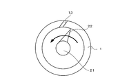
- the pin 4 is not provided in the through hole of the cylinder 1 closest to the compression unit 24, and a vacuum pump 5 disposed outside the cylinder 1 is connected. . That is, this through hole constitutes a deaeration hole 13 as will be described later, and discharges moisture, air, etc. in the rubber composition.
- pins 4 are attached to all the through holes 12 on the downstream side of the deaeration holes 13 and the upstream side of the compression portion 24, and these pins 4 extend to the gap region 23 of the screw blade 22. .
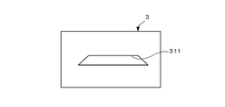
- the extrusion head 3 is attached to the discharge port 11 of the extruder 10, and a die plate 31 is provided at the tip. As shown in FIG. 2, the die plate 31 has an opening 311 formed in the cross-sectional shape of the tread to be molded.
- a preformer 32 is formed in a path from the discharge port 11 of the extruder 10 to the die plate 31, and the rubber composition is preformed.
- Rubber composition In the rubber composition used in the present embodiment, a silica-rich compound rubber containing a large amount of silica can be used. Such a silica-rich compounded rubber can exhibit excellent actual vehicle running performance such as improving wet grip performance and reducing heat generation and rolling resistance.
- Examples of the rubber polymer include natural rubber (NR), butadiene rubber (BR), styrene butadiene rubber (SBR), polyisoprene rubber (IR), nitrile rubber (NBR), and chloroprene rubber (CR). One or two or more of these can be blended and used.
- NR natural rubber
- BR butadiene rubber
- SBR styrene butadiene rubber
- IR polyisoprene rubber
- NBR nitrile rubber
- CR chloroprene rubber
- the silica to be blended is not particularly limited, but in order to improve the reinforcing effect on rubber and the rubber processability, the nitrogen adsorption specific surface area (BET) is in the range of 150 to 250 m 2 / g, and dibutyl phthalate. (DBP) The thing which shows the colloidal characteristic whose oil absorption amount is 180 ml / 100g or more is desirable.
- the silane coupling agent bis (triethoxysilylpropyl) tetrasulfide and ⁇ -mercaptopropyltrimethoxysilane are suitable.
- the compounding amount of silica is preferably 40 PHR or more, more preferably 50 PHR or more, relative to 100 PHR of the polymer.
- the rubber composition further generates heat while passing through the narrow groove 242 to increase the surface area, and a part of the components in the rubber composition and moisture are vaporized. In this way, by increasing the surface area, it is easy to discharge moisture contained therein to the rubber surface.
- the vaporized component is sucked by the vacuum pump 5 on the downstream side of the compression unit 24 and discharged from the deaeration hole 13 to the outside of the cylinder 1. Then, the rubber composition from which part of the components, moisture, and the like have disappeared is transferred further downstream by the screw 2 and discharged from the discharge port 11. In this process, the rubber composition is also heated by the pins 4 on the downstream side of the compression portion 24.
- the rubber composition thus discharged from the extruder is preformed into a band shape while passing through the preformer 32 of the extrusion head 3 and then passed through the opening 311 of the die plate 31 to form a tread shape. Is done.
- the plurality of pins 4 are provided on the inner wall surface of the cylinder 1, it is not necessary to narrow the pitch of a part of the screw blades for hot-heating as in, for example, a vent type extruder. Therefore, the pitch of the screw blades 22 can be widened, thereby increasing the discharge amount.
- a cylinder as used in a conventional pin type extruder can be used.
- a part of the rubber composition may be discharged from the deaeration holes 13. In that case, what is necessary is just to change the position of the deaeration hole 13 suitably. That is, the through hole used as the deaeration hole 13 can be changed.
- the position of the compression unit 24 can be changed according to the type of the rubber composition.
- a plurality of screws 2 having different positions of the compression part 24 can be used properly depending on the type of rubber composition.
- the pin 4 is not provided at the position where the compression unit 24 is disposed, but the position where the pin 4 is not provided can be easily changed according to the screw 2.
- the pitch of the screw blades 22 is made uniform over the entire axial direction. However, as long as the discharge amount is not greatly reduced, a part of the pitch may be changed according to the type of the rubber composition. You can also.
- one compression unit 24 is provided, but two or more compression units 24 may be provided.
- a deaeration hole can be provided on the downstream side of each compression unit 24. If it is set as such a structure, deaeration from a rubber composition can be performed in multiple times. Further, the number of deaeration holes 13 is not particularly limited, and a plurality of deaeration holes 13 may be provided. Further, the gas can be sucked from the deaeration holes other than the vacuum pump as long as the gas can be sucked, and various pumps can be applied.
- the structure of the compression part 24 is not limited to the said embodiment, What is necessary is just a structure which can compress and heat-generate a rubber composition with passage.
- a compression portion 28 having a diameter larger than that of the shaft 21 can be provided instead of the compression portion 24 of FIG. 1.
- the compression portion 28 is formed in a cylindrical shape having a predetermined length in the axial direction, and has a small clearance with the inner wall surface of the cylinder 1. Further, it is inclined similarly to the screw blade 22. Even when such a compression unit 28 is used, the rubber composition supplied from the upstream side passes while being compressed between the compression unit 28 and the inner wall surface of the cylinder 1, and moisture and the like in the rubber composition are vaporized. To do.
- the cylinder 1 can have various configurations.
- the deaeration hole can be inclined in a direction away from the rotation direction of the screw. Thereby, it is possible to prevent the rubber composition from being clogged in the deaeration holes.
- a cylinder like a pin type extruder may be a cylinder which does not provide a through-hole and attaches a pin directly to an inner wall surface, and a deaeration hole is also required. It may be provided appropriately at various locations. Further, the shape of the pin is not particularly limited.
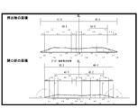
- Diameter 90mm L / D (ratio of screw length L to screw diameter): 12 ⁇ Temperature control (extrusion head, screw, cylinder): 90 °C ⁇ 80 °C ⁇ 60 °C ⁇ Die factor (cross-sectional area of die plate opening (mm 2 ) / extruded cross-sectional area (mm 2 ) ⁇ 1 00): 62.5% (the specific shape is as shown in FIG. 6)
- Tan ⁇ 0 ° C. 0.73.
- -Bubble area ratio (%): The recessed area (mm 2 ) / cross-sectional area (mm 2 ) of the extrudate was calculated. This was calculated by 3D analysis using a microscope. If the bubble area ratio is 2% or more, for example, the shape is not stable, which causes a problem in tire performance.
- Table 1 shows the results of the method according to the example
- Table 2 shows the results of the method according to the comparative example.
- the method according to the comparative example has lower WET performance and RCC evaluation than the method according to the example. Moreover, it turns out that the bubble area ratio is getting worse when the rotation speed of the screw is 30 rpm or more. Furthermore, it has also been found that when the number of rotations of the screw is 40 rpm or more, a problem occurs in the shape. In particular, when the number of rotations of the screw is 50 rpm or more, problems occur in most treads. Further, in the method according to the comparative example, there is no problem in the shape at the rotation speed of 30 rpm or less, but there is a problem that the productivity is lowered at 30 rpm or less.
- the WET performance was high and the rolling performance was high because the RRC was low. That is, these performance evaluations are higher and more stable than the comparative examples. And even if the rotation speed of the screw became high, the bubble area ratio was almost 0%. In addition, there was no problem in the shape at any rotational speed. Therefore, in the method according to the example, it was found that the performance of the molded tread was higher and the productivity was higher than that of the comparative example.
Landscapes
- Engineering & Computer Science (AREA)
- Mechanical Engineering (AREA)
- Extrusion Moulding Of Plastics Or The Like (AREA)
- Compositions Of Macromolecular Compounds (AREA)
Abstract
本発明に係るゴム部材の製造方法は、押出機のシリンダに、ゴム組成物を供給するステップと、シリンダの内壁面から複数の突出部材が突出する当該シリンダの内部空間において、ゴム組成物を混練りしつつ、シリンダの下流側に押し出すステップと、ゴム組成物を下流側に押し出すステップにおいて、少なくとも1回、ゴム組成物を圧縮するステップと、圧縮されたゴム組成物から発生する気体を、シリンダの外部に排出するステップと、気体が発生した後のゴム組成物を、シリンダの吐出口から排出するステップと、吐出口から排出されたゴム組成物を、所定のゴム部材の形状に成形するステップと、を備えている。
Description
本発明は、ゴム部材の製造方法に関する。
従来より、ゴム組成物や合成樹脂など被混練物を混練するための種々の押出機が提案されている。例えば、特許文献1には、いわゆるピン型押出機が開示されている。ピン型押出機では、シリンダの内壁面に多数のピンを突出させ、このピンによって、被混練物に対する熱入れが可能となる。そして、このような押出機から押し出された被混練物は、ダイプレートを含む押出しヘッドを通過することにより成形され、所望の形状のゴム部材が得られるように構成されている。
しかしながら、このようなピン型押出機においては、所望のタイヤ性能を得るため、さらなる改良が望まれていた。
本発明は、この問題を解決するためになされたものであり、被混練物から発生した気体による不具合を防止し、しかも生産性を高めることができる、ゴム部材の製造方法を提供することを目的とする。
本発明に係るゴム部材の製造方法は、押出機のシリンダに、ゴム組成物を供給するステップと、前記シリンダの内壁面から複数の突出部材が突出する当該シリンダの内部空間において、前記ゴム組成物を混練りしつつ、前記シリンダの下流側に押し出すステップと、前記ゴム組成物を前記下流側に押し出すステップにおいて、少なくとも1回、前記ゴム組成物を圧縮するステップと、圧縮された前記ゴム組成物から発生する気体を、前記シリンダの外部に排出するステップと、前記気体が発生した後のゴム組成物を、前記シリンダの吐出口から排出するステップと、前記吐出口から排出されたゴム組成物を、所定のゴム部材の形状に成形するステップと、を備えている。
上記ゴム部材の製造方法において、前記ゴム組成物を圧縮するステップでは、当該ゴム組成物を複数のスリットを通過させることができる。
上記各ゴム部材の製造方法においては、前記吐出口から排出されたゴム組成物の温度は、低くすることができ、例えば、135℃以下、130℃以下、125℃以下、または120℃以下とすることができる。
上記各ゴム部材の製造方法において、前記ゴム組成物は、ポリマー100PHRに対し、シリカを40PHR以上配合したものとすることができる。
上記各ゴム部材の製造方法において、前記ゴム組成物から発生した気体は、真空ポンプによって前記シリンダの外部に吸引することができる。
本発明に係るゴム部材の製造方法によれば、被混練物から発生した気体による不具合を防止し、しかも生産性を高めることができる。
以下、本発明に係るゴム部材の製造方法をタイヤ用トレッドの製造方法に適用した一実施形態について、図面を参照しつつ説明する。図1は、この製造方法に用いる押出機10及び押出しヘッド3の概略を示す断面図、図2は、押出しヘッドの正面図である。
<1.押出機の構造>
図1に示すように、本実施形態に係る押出機10は、荒ゴムなどのゴム組成物を供給し、混練して押し出すものである。図1に示すように、この押出機は、円筒状のシリンダ1と、このシリンダ1内で回転するスクリュー2と、を備えている。このシリンダ1において、図1の左側に位置する第1端部には、混練されたゴムが吐出される吐出口11を有し、図1の右側に位置する第2端部側には、スクリュー2を回転させるモータ6が配置されている。吐出口11は、要求に応じて内径が調整されており、本実施形態では、内径を小さくしている。
図1に示すように、本実施形態に係る押出機10は、荒ゴムなどのゴム組成物を供給し、混練して押し出すものである。図1に示すように、この押出機は、円筒状のシリンダ1と、このシリンダ1内で回転するスクリュー2と、を備えている。このシリンダ1において、図1の左側に位置する第1端部には、混練されたゴムが吐出される吐出口11を有し、図1の右側に位置する第2端部側には、スクリュー2を回転させるモータ6が配置されている。吐出口11は、要求に応じて内径が調整されており、本実施形態では、内径を小さくしている。
また、このシリンダ1において、第2端部側の上面には、ゴム組成物を供給するホッパ(供給部)8が取付けられており、このホッパ8はシリンダ1の内部空間に連通している。さらに、このシリンダ1には、軸方向に沿って所定間隔をおいて、且つ周方向に等間隔に複数の貫通孔12が形成されている。各貫通孔12は、シリンダ1の内外を連通させるとともに、いくつかの貫通孔12には、シリンダ1の内部空間に突出するピン(突出部材)4が着脱自在に取付けられている。各ピン4は、円筒状に形成され、後述するように、シリンダ1の軸心Xに向かって、スクリュー2のシャフト21に近接する位置まで延びている。
次に、スクリュー2について説明する。スクリュー2は、シリンダ1の軸心Xに沿って延びるシャフト21と、シャフト21の外周面に取付けられたスクリュー羽根22と、を備えている。このスクリュー羽根22のピッチは全長に亘って均等であるが、連続しておらず、軸方向に沿って所定間隔おきに分断されている。すなわち、シャフト21には、スクリュー羽根22が形成されていない隙間領域(切欠き部)23が、軸方向に所定間隔おきに設けられている。そして、この隙間領域23に、上述した各ピン4が延びるように、シリンダ1の貫通孔12が位置決めされている。なお、スクリュー羽根22を完全に分断せず、ピン4と干渉しないように、スクリュー羽根22の外周面から所定深さの切欠きを設けることもできる。また、ピン4の長さも適宜変更することができる。
また、このスクリュー2の中間部、つまりホッパ8と吐出口11との間には、ゴム組成物を圧縮する圧縮部24が設けられている。圧縮部24は次のように構成されている。まず、スクリュー羽根22において圧縮部24に相当する約360°の部分では、他の部分に比べ、スクリュー羽根22の外径が大きく、シリンダ1の内壁面に近接するように形成
されている。より詳細には、ゴム組成物によってスクリュー羽根22の外周面とシリンダ1の内壁面とがシールされるように、例えば、数mm程度のクリアランスを形成することができる。
されている。より詳細には、ゴム組成物によってスクリュー羽根22の外周面とシリンダ1の内壁面とがシールされるように、例えば、数mm程度のクリアランスを形成することができる。
また、この圧縮部24においては、隣接するスクリュー羽根22を連結するように、軸方向に延びる堰部241を備えている。堰部241は、シャフト21からの高さがスクリュー羽根22と同じになるように形成されており、これによってスクリュー羽根22の間を通るゴム組成物は堰部241で堰き止められ、下流側に移送されないようになっている。これに対し、圧縮部24において、スクリュー羽根22の外周面には、堰部241の前端部と後端部を結ぶように約360°に亘って、軸方向に延びる複数の細い溝242が所定間隔おきに形成されている。したがって、堰部で堰き止められたゴム組成物は、これら溝242を介してシリンダ1の下流側に移送されるようになっている。
そして、シリンダ1において、スクリュー羽根22の圧縮部24に相当する部分には、ピン4が設けられていない。すなわち、貫通孔12にピン4を設けず、単に貫通孔12を閉鎖する。また、圧縮部24の下流側において、圧縮部24に最も近接するシリンダ1の貫通孔には、ピン4が設けられておらず、シリンダ1の外部に配置された真空ポンプ5が連結されている。すなわち、この貫通孔は、後述するように脱気孔13を構成し、ゴム組成物内の水分、空気などを排出するようになっている。そして、この脱気孔13よりも下流側及び圧縮部24の上流側には、すべての貫通孔12にピン4が取付けられており、これらピン4は、スクリュー羽根22の隙間領域23に延びている。
<2.押出しヘッドの構造>
次に、押出しヘッドについて、図2も参照しつつ説明する。押出しヘッド3は、押出機10の吐出口11に取付けられており、先端には、ダイプレート31が設けられている。図2に示すように、ダイプレート31は、成形すべきトレッドの断面形状に形成された開口部311を有している。また、押出しヘッド3において、押出機10の吐出口11からダイプレート31に至る経路には、プリフォーマ32が形成されており、ゴム組成物の予成形が行われる。
次に、押出しヘッドについて、図2も参照しつつ説明する。押出しヘッド3は、押出機10の吐出口11に取付けられており、先端には、ダイプレート31が設けられている。図2に示すように、ダイプレート31は、成形すべきトレッドの断面形状に形成された開口部311を有している。また、押出しヘッド3において、押出機10の吐出口11からダイプレート31に至る経路には、プリフォーマ32が形成されており、ゴム組成物の予成形が行われる。
<3.ゴム組成物>
本実施形態に用いられるゴム組成物では、シリカを多く配合したシリカリッチ配合ゴムを用いることができる。このようなシリカリッチ配合ゴムは、ウエットグリップ性能を高め、また発熱や転がり抵抗を低減するなど優れた実車走行性能を発揮しうる。
本実施形態に用いられるゴム組成物では、シリカを多く配合したシリカリッチ配合ゴムを用いることができる。このようなシリカリッチ配合ゴムは、ウエットグリップ性能を高め、また発熱や転がり抵抗を低減するなど優れた実車走行性能を発揮しうる。
ゴムポリマーには、例えば天然ゴム(NR)、ブタジエンゴム(BR)、スチレンブタジエンゴム(SBR)ポリイソプレンゴム(IR)、ニトリルゴム(NBR)又はクロロプレンゴム(CR)などを挙げることができ、これらの1種又は2種以上をブレンドして用いることができる。
また、配合されるシリカとしては、特に限定はされないが、ゴムへの補強効果及びゴム加工性を高めるために、窒素吸着比表面積(BET)が150~250m2/gの範囲、かつフタル酸ジブチル(DBP)吸油量が180ml/100g以上のコロイダル特性を示すものが望ましい。
また、シランカップリング剤としては、ビス(トリエトキシシリルプロピル)テトラスルフィド、α-メルカプトプロピルトリメトキシシランが好適である。なお、低転がり抵抗性とウエットグリップ性とをより高いレベルで両立させるために、シリカの配合量は、ポリマー100PHRに対し、40PHR以上配合することが好ましく、50PHR以上配合することがさらに好ましい。
<4.押出機及び押出しヘッドの動作>
次に、上記のように構成された押出機の動作について説明する。まず、モータを駆動してスクリュー2を回転させる。また、真空ポンプ5も駆動しておく。次に、ホッパ8からゴム組成物を投入する。投入されたゴム組成物は、スクリュー2の回転により下流側へ移送される。このとき、ゴム組成物は、スクリュー羽根22の間を通過しつつ、ピン4により剪断力が付与されるため、その摩擦によってゴム組成物には熱入れがなされる。そして、圧縮部24に到達したゴム組成物は、堰部241によって堰き止められ、スクリュー羽根22の間からは下流側に移送できないため、スクリュー羽根22の外周面に形成された溝242から下流側へ移送される。このとき、溝242は、スクリュー羽根22の外周面に約360度に亘って形成されているため、溝242を通過するゴム組成物は、円筒状に形成されつつ下流側へ移送される。
次に、上記のように構成された押出機の動作について説明する。まず、モータを駆動してスクリュー2を回転させる。また、真空ポンプ5も駆動しておく。次に、ホッパ8からゴム組成物を投入する。投入されたゴム組成物は、スクリュー2の回転により下流側へ移送される。このとき、ゴム組成物は、スクリュー羽根22の間を通過しつつ、ピン4により剪断力が付与されるため、その摩擦によってゴム組成物には熱入れがなされる。そして、圧縮部24に到達したゴム組成物は、堰部241によって堰き止められ、スクリュー羽根22の間からは下流側に移送できないため、スクリュー羽根22の外周面に形成された溝242から下流側へ移送される。このとき、溝242は、スクリュー羽根22の外周面に約360度に亘って形成されているため、溝242を通過するゴム組成物は、円筒状に形成されつつ下流側へ移送される。
そして、ゴム組成物は、細い溝242を通過することで表面積を増やしながら、さらに発熱し、ゴム組成物中の成分の一部や水分などが気化する。このように、表面積を増加させることで、内包する水分等をゴムの表面に排出させやすくする。こうして気化した成分は、圧縮部24の下流側において真空ポンプ5により吸引され、脱気孔13からシリンダ1の外部に排出される。そして、成分の一部や水分などが消失したゴム組成物は、スクリュー2によりさらに下流側に移送され、吐出口11から吐出される。この過程において、圧縮部24の下流側でも、ゴム組成物はピン4により熱入れがなされる。
こうして押出機から吐出されたゴム組成物は、押出しヘッド3のプリフォーマ32を通過しつつ、帯状に予成形された後、ダイプレート31の開口部311を通過することで、トレッドの形状に成形される。
<5.特徴>
以上のように、本実施形態によれば、押出機10に脱気孔13を設けているため、圧縮部24で発熱したゴム組成物から発生した気体をシリンダ1の外部に放出することができる。そのため、混練されるゴム組成物に気体が含まれるのを防止することができる。その結果、成形されたトレッドを、所望の形状とすることができる。
以上のように、本実施形態によれば、押出機10に脱気孔13を設けているため、圧縮部24で発熱したゴム組成物から発生した気体をシリンダ1の外部に放出することができる。そのため、混練されるゴム組成物に気体が含まれるのを防止することができる。その結果、成形されたトレッドを、所望の形状とすることができる。
また、気体がゴムとシリカとの反応を阻害するのを防止することができ、シリカを適切に分散させることができる。これにより、WET性能、転がり抵抗などのタイヤ性能を向上することができる。また、シリカ以外の薬剤についても同様である。
また、気体が発生しないように、低温で押出機を駆動する必要がなく、そのため、スクリュー2の回転速度を高くすることができる。その結果、生産性を向上することができる。
また、シリンダ1の内壁面に複数のピン4が設けられているため、例えば、ベント式押出機のように、熱入れのためにスクリュー羽根の一部のピッチを狭くする必要がない。そのため、スクリュー羽根22のピッチを広くすることができ、これによって吐出量を増大させることができる。
また、本実施形態の押出機では、従来のピン型押出機で用いられるようなシリンダを利用することができる。これにより、次の利点がある。すなわち、一般的なピン型押出機のシリンダには、ピンを取付けるための貫通孔が予め形成されており、この貫通孔にピンを着脱自在に取付けることができる。したがって、このようなシリンダを用いれば、例えば、ゴム組成物に対する必要な熱入れの量に応じて、ピンの数を適宜変更することができる。すなわち、すべての貫通孔にピンを取付けることができるほか、一部の貫通孔にのみピ
ンを取付けることができる。そして、ピンを設けない場合には、キャップなどで貫通孔を閉鎖すればよい。
ンを取付けることができる。そして、ピンを設けない場合には、キャップなどで貫通孔を閉鎖すればよい。
また、ゴム組成物の種類によっては、ゴム組成物の一部が脱気孔13から排出されるおそれがある。その場合には、脱気孔13の位置を適宜変更すればよい。すなわち、脱気孔13として利用する貫通孔を変更することができる。
さらに、ゴム組成物の種類に応じて、圧縮部24の位置を変更することができる。例えば、圧縮部24の位置が異なる複数のスクリュー2をゴム組成物の種類によって使い分けすることができる。このとき、シリンダ1において、圧縮部24が配置される位置にはピン4を設けないが、ピン4を設けない位置もスクリュー2に合わせて簡単に変更することができる。
このように、ピン型押出機で用いられるような複数の貫通孔が予め形成されているシリンダを用いれば、ピンの位置のみならず、脱気孔の位置も適宜変更することができる。
<6.変形例>
以上、本発明の一実施形態について説明したが、本発明は上記実施形態に限定されるものではなく、その趣旨を逸脱しない限りにおいて、種々の変更が可能である。なお、以下の変形例は適宜組み合わせることができる。
以上、本発明の一実施形態について説明したが、本発明は上記実施形態に限定されるものではなく、その趣旨を逸脱しない限りにおいて、種々の変更が可能である。なお、以下の変形例は適宜組み合わせることができる。
<6-1>
上記実施形態では、スクリュー羽根22のピッチが軸方向全体に亘って均等にしているが、吐出量が大きく減少しない限りにおいては、ゴム組成物の種類などに応じて、一部のピッチを変えることもできる。
上記実施形態では、スクリュー羽根22のピッチが軸方向全体に亘って均等にしているが、吐出量が大きく減少しない限りにおいては、ゴム組成物の種類などに応じて、一部のピッチを変えることもできる。
<6-2>
上記実施形態では、圧縮部24を1つ設けているが、2以上設けることもできる。この場合、各圧縮部24の下流側に脱気孔を設けることができる。このような構成にすると、ゴム組成物からの脱気を複数回に亘って行うことができる。また、脱気孔13の数も特には限定されず、複数設けることもできる。また、脱気孔から気体を吸引するのは、気体が吸引できれば、真空ポンプ以外でもよく、種々のポンプを適用することができる。
上記実施形態では、圧縮部24を1つ設けているが、2以上設けることもできる。この場合、各圧縮部24の下流側に脱気孔を設けることができる。このような構成にすると、ゴム組成物からの脱気を複数回に亘って行うことができる。また、脱気孔13の数も特には限定されず、複数設けることもできる。また、脱気孔から気体を吸引するのは、気体が吸引できれば、真空ポンプ以外でもよく、種々のポンプを適用することができる。
<6-3>
圧縮部24の構成は、上記実施形態に限定されるものではなく、通過に伴ってゴム組成物を圧縮して発熱させることができるような構成であればよい。例えば、図3に示すように、図1の圧縮部24に代えて、シャフト21よりも大径の圧縮部28を設けることができる。この圧縮部28は、軸方向に所定の長さを有する円筒状に形成され、シリンダ1の内壁面との間に小さいクリアランスを有している。また、スクリュー羽根22と同様に傾いている。このような圧縮部28を用いても、上流側から供給されたゴム組成物が、圧縮部28とシリンダ1の内壁面との間で圧縮されながら通過し、ゴム組成物内の水分等が気化する。
圧縮部24の構成は、上記実施形態に限定されるものではなく、通過に伴ってゴム組成物を圧縮して発熱させることができるような構成であればよい。例えば、図3に示すように、図1の圧縮部24に代えて、シャフト21よりも大径の圧縮部28を設けることができる。この圧縮部28は、軸方向に所定の長さを有する円筒状に形成され、シリンダ1の内壁面との間に小さいクリアランスを有している。また、スクリュー羽根22と同様に傾いている。このような圧縮部28を用いても、上流側から供給されたゴム組成物が、圧縮部28とシリンダ1の内壁面との間で圧縮されながら通過し、ゴム組成物内の水分等が気化する。
<6-4>
シリンダ1は、種々の構成にすることができるが、例えば、図4に示すように、脱気孔をスクリューの回転方向から離れる方向に傾斜させることができる。これにより、脱気孔にゴム組成物が詰まるのを防止することができる。
シリンダ1は、種々の構成にすることができるが、例えば、図4に示すように、脱気孔をスクリューの回転方向から離れる方向に傾斜させることができる。これにより、脱気孔にゴム組成物が詰まるのを防止することができる。
<6-5>
また、上記実施形態では、ピン型押出機のようなシリンダを利用した態様を示している
が、貫通孔を設けず、内壁面に直接ピンを取付けるようなシリンダであってよく、脱気孔も必要な箇所に適宜設けたものであってもよい。また、ピンの形状も特には限定されない。
また、上記実施形態では、ピン型押出機のようなシリンダを利用した態様を示している
が、貫通孔を設けず、内壁面に直接ピンを取付けるようなシリンダであってよく、脱気孔も必要な箇所に適宜設けたものであってもよい。また、ピンの形状も特には限定されない。
<6-6>
上記実施形態では、ゴム組成物を混練して押し出し、トレッドを成形する場合について説明したが、押出しヘッドを適宜交換することで、種々の形態のトレッドの製造に適用することができる。また、トレッド以外のタイヤのパーツや、種々のゴム部材の製造にも適用することができる。
上記実施形態では、ゴム組成物を混練して押し出し、トレッドを成形する場合について説明したが、押出しヘッドを適宜交換することで、種々の形態のトレッドの製造に適用することができる。また、トレッド以外のタイヤのパーツや、種々のゴム部材の製造にも適用することができる。
以下、本発明に係る実施例について説明する。但し、本発明は、以下の実施例に限定されない。
(1.押出機及び押出しヘッド)
実施例に係る方法を実施するため、上記実施形態に係る図1に示すような押出機及び押出しヘッドを準備した。一方、比較例としては、次の装置を用いた。すなわち、図5に示すように、実施例に係る押出機において、真空ポンプを設けず、シリンダにおいて脱気孔として用いた貫通孔を塞ぎ、この押出機を用いた方法を比較例とした。
また、押出機の仕様は以下の通りである。
・直径:90mm
・L/D(スクリュー長さLとスクリュー径の比):12
・温調(押出しヘッド・スクリュー・シリンダ):90℃・80℃・60℃
・ダイファクター(ダイプレートの開口部の断面積(mm2)/押出物の断面積(mm2)×1
00):62.5%(具体的な形状は図6に示すとおりである。)
(2.ゴム組成物)
・配合:シリカ55PHRのトレッド配合
・練ゴムでのシリカ分散:95.2%
・配合:シリカ55PHRのトレッド配合
・練ゴムでのシリカ分散:95.2%
(3.トレッドの製造及び評価)
上記のようなゴム組成物を用い、実施例及び比較例に係る押出機及び押出しヘッドにより、タイヤ100本分のトレッドを成形した。その際、スクリューの回転数を変化させ、以下の項目を測定した。
・吐出時の温度:サーモセンサーで成形されたトレッドの表面温度を測定し、最大時の温度とした。
・形状不適合トレッドの発生量(%):各ポイントでの仕様±0.5mmより外れた本数/100本×100として算出した。
・タイヤ性能(WET性能:Tanδ0℃):アルファーテクノロジー社製RPA2000を用い、Tanδ0℃を測定した。なお、練ゴムでは、Tanδ0℃=0.73であった。
・転がり性能(RRC:Tanδ30℃):アルファーテクノロジー社製RPA2000を用い、Tanδ30℃を測定した。なお、練ゴムでは、Tanδ30℃=0.33であった。
・気泡面積比率(%):凹んだ面積(mm2)/押出物の断面積(mm2)を算出した。これは、マイクロスコープによる3D解析により算出した。気泡面積比率は、例えば、2%以上であれば、形状が安定しないため、タイヤ性能に問題が生じる。
結果は、以下の通りである。表1が実施例に係る方法の結果であり、表2が比較例に係る方法の結果である。
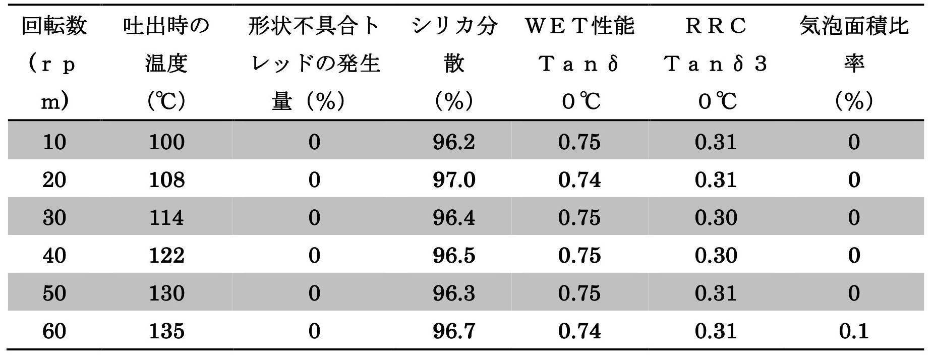
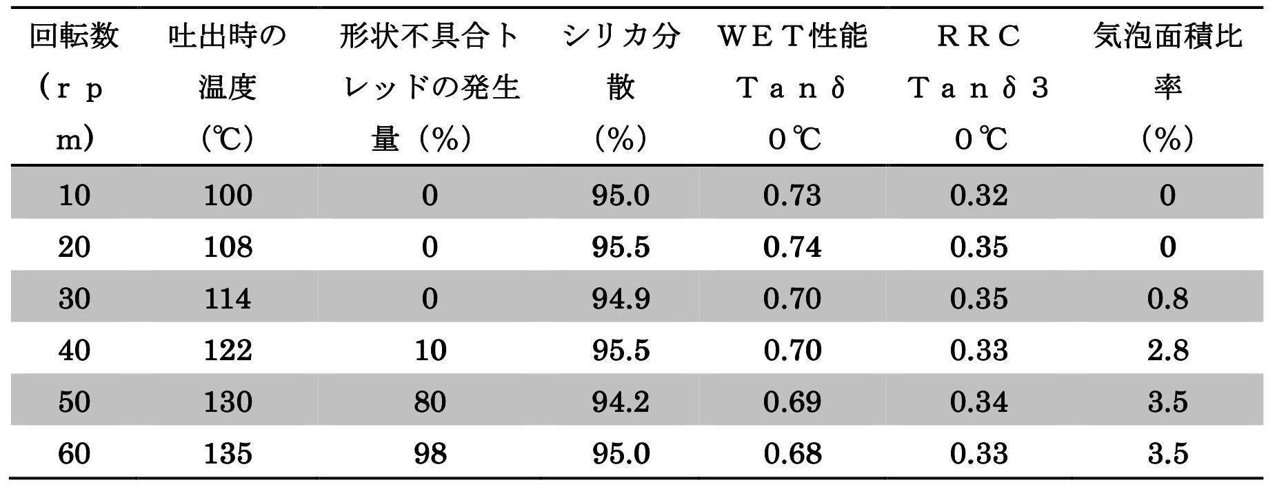
上記の結果によれば、比較例に係る方法では、WET性能及びRCCの評価が、実施例に係る方法に比べ、低いことが分かった。また、スクリューの回転数が30rpm以上となると、気泡面積比率が悪化していることが分かる。さらに、スクリューの回転数が40rpm以上となると、形状に不具合が発生することも分かった。特に、スクリューの回転数が50rpm以上になると、大半のトレッドで不具合が発生している。また、比較例に係る方法では、30rpm以下の回転数では、形状に不具合は発生していないが、30rpm以下では生産性が低下するという問題がある。一方、実施例に係る方法では、比較例に比べ、WET性能が高く、またRRCが低いため転がり性能が高かった。すなわち、これらの性能の評価は、比較例に比べて高く、安定している。そして、スクリューの回転数が高くなっても気泡面積比率はほぼ0%であった。また、いずれの回転数においても、形状に不具合は発生しなかった。したがって、実施例に係る方法では、比較例に比べ、成形されるトレッドの性能が高く、また生産性も高いことが分かった。
1 :シリンダ
11 :吐出口
12 :貫通孔
13 :脱気孔
2 :スクリュー
242 :溝
4 :ピン(突出部材)
11 :吐出口
12 :貫通孔
13 :脱気孔
2 :スクリュー
242 :溝
4 :ピン(突出部材)
Claims (4)
- 押出機のシリンダに、ゴム組成物を供給するステップと、
前記シリンダの内壁面から複数の突出部材が突出する当該シリンダの内部空間において、前記ゴム組成物を混練りしつつ、前記シリンダの下流側に押し出すステップと、
前記ゴム組成物を前記下流側に押し出すステップにおいて、少なくとも1回、前記ゴム組成物を圧縮するステップと、
圧縮された前記ゴム組成物から発生する気体を、前記シリンダの外部に排出するステップと、
前記気体が発生した後のゴム組成物を、前記シリンダの吐出口から排出するステップと、
前記吐出口から排出されたゴム組成物を、所定のゴム部材の形状に成形するステップと、
を備えている、ゴム部材の製造方法。 - 前記ゴム組成物を圧縮するステップでは、当該ゴム組成物を複数のスリットを通過させる、請求項1に記載のゴム部材の製造方法。
- 前記ゴム組成物は、ポリマー100PHRに対し、シリカが40PHR以上配合されている、請求項1または2に記載のゴム部材の製造方法。
- 前記ゴム組成物から発生した気体は、真空ポンプによって前記シリンダの外部に吸引される、請求項1から3のいずれかに記載のゴム部材の製造方法。
Priority Applications (3)
| Application Number | Priority Date | Filing Date | Title |
|---|---|---|---|
| EP17747169.5A EP3409441B1 (en) | 2016-02-05 | 2017-01-12 | Method for producing rubber member |
| US16/073,407 US11097447B2 (en) | 2016-02-05 | 2017-01-12 | Method for producing rubber member |
| CN201780009542.7A CN108602229A (zh) | 2016-02-05 | 2017-01-12 | 橡胶部件的制造方法 |
Applications Claiming Priority (2)
| Application Number | Priority Date | Filing Date | Title |
|---|---|---|---|
| JP2016-021376 | 2016-02-05 | ||
| JP2016021376A JP6736899B2 (ja) | 2016-02-05 | 2016-02-05 | ゴム部材の製造方法 |
Publications (1)
| Publication Number | Publication Date |
|---|---|
| WO2017135007A1 true WO2017135007A1 (ja) | 2017-08-10 |
Family
ID=59500686
Family Applications (1)
| Application Number | Title | Priority Date | Filing Date |
|---|---|---|---|
| PCT/JP2017/000900 WO2017135007A1 (ja) | 2016-02-05 | 2017-01-12 | ゴム部材の製造方法 |
Country Status (5)
| Country | Link |
|---|---|
| US (1) | US11097447B2 (ja) |
| EP (1) | EP3409441B1 (ja) |
| JP (1) | JP6736899B2 (ja) |
| CN (1) | CN108602229A (ja) |
| WO (1) | WO2017135007A1 (ja) |
Cited By (1)
| Publication number | Priority date | Publication date | Assignee | Title |
|---|---|---|---|---|
| JP2019119050A (ja) * | 2017-12-28 | 2019-07-22 | Toyo Tire株式会社 | 連続混練単軸押出機およびゴム組成物の製造方法 |
Families Citing this family (4)
| Publication number | Priority date | Publication date | Assignee | Title |
|---|---|---|---|---|
| CN111633947B (zh) * | 2019-03-01 | 2023-11-10 | 住友橡胶工业株式会社 | 橡胶挤出机以及橡胶挤出方法 |
| CN110920024B (zh) * | 2019-11-29 | 2021-05-28 | 重庆瑞霆塑胶有限公司 | 耐高温薄膜的挤出供料装置 |
| JP6754018B1 (ja) * | 2020-01-23 | 2020-09-09 | 中田エンヂニアリング株式会社 | スクリュー、押出機及び押出方法 |
| CN115302650B (zh) * | 2022-08-30 | 2024-05-24 | 承德石油高等专科学校 | 一种基于绿色环保的橡胶密炼加工设备 |
Citations (8)
| Publication number | Priority date | Publication date | Assignee | Title |
|---|---|---|---|---|
| JPS62273821A (ja) * | 1986-05-22 | 1987-11-27 | Kobe Kikai Kk | スクリユ−押出機において粘性材料中のガス分及び水分を除去する方法とその装置 |
| JPH04276423A (ja) * | 1990-12-14 | 1992-10-01 | Hermann Berstorff Mas Gmbh | 脱気用押出機 |
| JPH1177667A (ja) * | 1997-09-10 | 1999-03-23 | Bridgestone Cycle Co | ピン押出機 |
| JP2004237715A (ja) * | 2002-12-11 | 2004-08-26 | Sumitomo Rubber Ind Ltd | 押出機および押出方法 |
| JP2008018581A (ja) * | 2006-07-12 | 2008-01-31 | Japan Steel Works Ltd:The | 熱可塑性樹脂組成物の製造方法 |
| JP2008132672A (ja) * | 2006-11-28 | 2008-06-12 | Kobe Steel Ltd | 混練スクリュー、2軸押出機、及び混練スクリューの組み立て方法 |
| JP2010089423A (ja) * | 2008-10-09 | 2010-04-22 | Sumitomo Rubber Ind Ltd | タイヤ用ゴムの混練方法及び装置 |
| WO2014084404A1 (ja) * | 2012-11-30 | 2014-06-05 | コンパニー ゼネラール デ エタブリッスマン ミシュラン | 空気入りタイヤ用トレッド及びこのトレッドを有する空気入りタイヤ |
Family Cites Families (11)
| Publication number | Priority date | Publication date | Assignee | Title |
|---|---|---|---|---|
| DE3275070D1 (de) * | 1982-08-26 | 1987-02-19 | Berstorff Gmbh Masch Hermann | Extruder with vent zone |
| EP0490360B1 (de) * | 1990-12-14 | 1994-07-13 | HERMANN BERSTORFF Maschinenbau GmbH | Verfahren und Extruder zur Verarbeitung und Herstellung von Kautschuk und thermoplastischen Kunststoffen |
| US5219589A (en) * | 1992-01-22 | 1993-06-15 | Bridgestone/Firestone, Inc. | Vented kneading pin for extruder |
| KR100853552B1 (ko) * | 2000-09-28 | 2008-08-21 | 베르스토르프 게엠베하 | 고점성 매질용 스크루 압출기와 기어 펌프의 조립체 |
| JP2004142383A (ja) * | 2002-10-28 | 2004-05-20 | Toyo Tire & Rubber Co Ltd | ゴムの真空式押出機 |
| JP4338668B2 (ja) | 2005-04-05 | 2009-10-07 | 住友ゴム工業株式会社 | ゴム押出機 |
| JP2008230060A (ja) * | 2007-03-20 | 2008-10-02 | Bridgestone Corp | ゴム押出機及び押出方法 |
| KR101046615B1 (ko) * | 2008-12-24 | 2011-07-05 | 한국타이어 주식회사 | 초음파 발생 핀이 구비된 콜드피드압출기 |
| CN102784572A (zh) | 2011-05-20 | 2012-11-21 | 日东电工株式会社 | 混炼机 |
| ES2658079T3 (es) * | 2013-07-11 | 2018-03-08 | Ineos Styrolution Group Gmbh | Procedimiento para la producción de masas de moldeo termoplásticas, así como masas de moldeo termoplásticas producidas según éste |
| JP6217328B2 (ja) * | 2013-11-11 | 2017-10-25 | 信越化学工業株式会社 | 太陽電池封止用紫外線遮蔽性シリコーン接着剤シート並びにそれを用いた太陽電池モジュール |
-
2016
- 2016-02-05 JP JP2016021376A patent/JP6736899B2/ja active Active
-
2017
- 2017-01-12 EP EP17747169.5A patent/EP3409441B1/en active Active
- 2017-01-12 US US16/073,407 patent/US11097447B2/en active Active
- 2017-01-12 WO PCT/JP2017/000900 patent/WO2017135007A1/ja active Application Filing
- 2017-01-12 CN CN201780009542.7A patent/CN108602229A/zh active Pending
Patent Citations (8)
| Publication number | Priority date | Publication date | Assignee | Title |
|---|---|---|---|---|
| JPS62273821A (ja) * | 1986-05-22 | 1987-11-27 | Kobe Kikai Kk | スクリユ−押出機において粘性材料中のガス分及び水分を除去する方法とその装置 |
| JPH04276423A (ja) * | 1990-12-14 | 1992-10-01 | Hermann Berstorff Mas Gmbh | 脱気用押出機 |
| JPH1177667A (ja) * | 1997-09-10 | 1999-03-23 | Bridgestone Cycle Co | ピン押出機 |
| JP2004237715A (ja) * | 2002-12-11 | 2004-08-26 | Sumitomo Rubber Ind Ltd | 押出機および押出方法 |
| JP2008018581A (ja) * | 2006-07-12 | 2008-01-31 | Japan Steel Works Ltd:The | 熱可塑性樹脂組成物の製造方法 |
| JP2008132672A (ja) * | 2006-11-28 | 2008-06-12 | Kobe Steel Ltd | 混練スクリュー、2軸押出機、及び混練スクリューの組み立て方法 |
| JP2010089423A (ja) * | 2008-10-09 | 2010-04-22 | Sumitomo Rubber Ind Ltd | タイヤ用ゴムの混練方法及び装置 |
| WO2014084404A1 (ja) * | 2012-11-30 | 2014-06-05 | コンパニー ゼネラール デ エタブリッスマン ミシュラン | 空気入りタイヤ用トレッド及びこのトレッドを有する空気入りタイヤ |
Non-Patent Citations (1)
| Title |
|---|
| See also references of EP3409441A4 * |
Cited By (1)
| Publication number | Priority date | Publication date | Assignee | Title |
|---|---|---|---|---|
| JP2019119050A (ja) * | 2017-12-28 | 2019-07-22 | Toyo Tire株式会社 | 連続混練単軸押出機およびゴム組成物の製造方法 |
Also Published As
| Publication number | Publication date |
|---|---|
| JP6736899B2 (ja) | 2020-08-05 |
| US11097447B2 (en) | 2021-08-24 |
| EP3409441A1 (en) | 2018-12-05 |
| CN108602229A (zh) | 2018-09-28 |
| JP2017136804A (ja) | 2017-08-10 |
| EP3409441A4 (en) | 2019-08-14 |
| US20190358855A1 (en) | 2019-11-28 |
| EP3409441B1 (en) | 2021-11-24 |
Similar Documents
| Publication | Publication Date | Title |
|---|---|---|
| WO2017135007A1 (ja) | ゴム部材の製造方法 | |
| EP2338655B1 (en) | Continuous mixing apparatus and method | |
| EP2338662B1 (en) | Method of forming a rubber article and apparatus | |
| CN106863748B (zh) | 挤压机 | |
| CA2168282A1 (en) | Continuous mixing of silica loaded elastomeric compounds | |
| US7476096B2 (en) | Screw extruder | |
| JP2010089423A (ja) | タイヤ用ゴムの混練方法及び装置 | |
| EP2338660B1 (en) | Apparatus and method for applying rubber mixture on a core | |
| EP2574443B1 (en) | Method for forming a tire component and pneumatic tire | |
| KR20120124409A (ko) | 점탄성 물질을 압출하기 위한 스크류 공급 요소, 및 용도 및 방법 | |
| CN103419373A (zh) | 一种csm/nbr复合胶管的制备方法 | |
| WO2019031350A1 (ja) | ロール付スクリュ押出機 | |
| EP2468476A1 (en) | Extruder apparatus and method for forming tire components | |
| JP2019119050A (ja) | 連続混練単軸押出機およびゴム組成物の製造方法 | |
| EP3702125B1 (en) | Rubber extruder and method for extruding rubber | |
| WO2017183531A1 (ja) | スクリュ式押出機 | |
| WO2018198630A1 (ja) | ゴム組成物の製造方法およびタイヤの製造方法 | |
| WO2018142936A1 (ja) | スクリュ式押出機 | |
| JP7283132B2 (ja) | ゴム押出機及びゴム押出方法 | |
| EP2655029B1 (en) | Method for producing tyres | |
| JP2024102875A (ja) | トレッドゴム成形方法及びトレッドゴム | |
| JP2020138522A (ja) | ゴム押出機及びゴム押出方法 | |
| JP2024102876A (ja) | トレッドゴム成形装置及びトレッドゴム成形方法 |
Legal Events
| Date | Code | Title | Description |
|---|---|---|---|
| 121 | Ep: the epo has been informed by wipo that ep was designated in this application |
Ref document number: 17747169 Country of ref document: EP Kind code of ref document: A1 |
|
| NENP | Non-entry into the national phase |
Ref country code: DE |
|
| WWE | Wipo information: entry into national phase |
Ref document number: 2017747169 Country of ref document: EP |
|
| ENP | Entry into the national phase |
Ref document number: 2017747169 Country of ref document: EP Effective date: 20180828 |