WO2017134874A1 - 医療通信システム - Google Patents
医療通信システム Download PDFInfo
- Publication number
- WO2017134874A1 WO2017134874A1 PCT/JP2016/081762 JP2016081762W WO2017134874A1 WO 2017134874 A1 WO2017134874 A1 WO 2017134874A1 JP 2016081762 W JP2016081762 W JP 2016081762W WO 2017134874 A1 WO2017134874 A1 WO 2017134874A1
- Authority
- WO
- WIPO (PCT)
- Prior art keywords
- information
- dicom
- medical
- ultrasonic
- endoscope
- Prior art date
- Legal status (The legal status is an assumption and is not a legal conclusion. Google has not performed a legal analysis and makes no representation as to the accuracy of the status listed.)
- Ceased
Links
Images







Classifications
-
- G—PHYSICS
- G16—INFORMATION AND COMMUNICATION TECHNOLOGY [ICT] SPECIALLY ADAPTED FOR SPECIFIC APPLICATION FIELDS
- G16H—HEALTHCARE INFORMATICS, i.e. INFORMATION AND COMMUNICATION TECHNOLOGY [ICT] SPECIALLY ADAPTED FOR THE HANDLING OR PROCESSING OF MEDICAL OR HEALTHCARE DATA
- G16H30/00—ICT specially adapted for the handling or processing of medical images
- G16H30/20—ICT specially adapted for the handling or processing of medical images for handling medical images, e.g. DICOM, HL7 or PACS
-
- A—HUMAN NECESSITIES
- A61—MEDICAL OR VETERINARY SCIENCE; HYGIENE
- A61B—DIAGNOSIS; SURGERY; IDENTIFICATION
- A61B8/00—Diagnosis using ultrasonic, sonic or infrasonic waves
- A61B8/12—Diagnosis using ultrasonic, sonic or infrasonic waves in body cavities or body tracts, e.g. by using catheters
-
- A—HUMAN NECESSITIES
- A61—MEDICAL OR VETERINARY SCIENCE; HYGIENE
- A61B—DIAGNOSIS; SURGERY; IDENTIFICATION
- A61B8/00—Diagnosis using ultrasonic, sonic or infrasonic waves
- A61B8/56—Details of data transmission or power supply
- A61B8/565—Details of data transmission or power supply involving data transmission via a network
-
- G—PHYSICS
- G16—INFORMATION AND COMMUNICATION TECHNOLOGY [ICT] SPECIALLY ADAPTED FOR SPECIFIC APPLICATION FIELDS
- G16H—HEALTHCARE INFORMATICS, i.e. INFORMATION AND COMMUNICATION TECHNOLOGY [ICT] SPECIALLY ADAPTED FOR THE HANDLING OR PROCESSING OF MEDICAL OR HEALTHCARE DATA
- G16H15/00—ICT specially adapted for medical reports, e.g. generation or transmission thereof
-
- G—PHYSICS
- G16—INFORMATION AND COMMUNICATION TECHNOLOGY [ICT] SPECIALLY ADAPTED FOR SPECIFIC APPLICATION FIELDS
- G16H—HEALTHCARE INFORMATICS, i.e. INFORMATION AND COMMUNICATION TECHNOLOGY [ICT] SPECIALLY ADAPTED FOR THE HANDLING OR PROCESSING OF MEDICAL OR HEALTHCARE DATA
- G16H30/00—ICT specially adapted for the handling or processing of medical images
- G16H30/40—ICT specially adapted for the handling or processing of medical images for processing medical images, e.g. editing
-
- G—PHYSICS
- G16—INFORMATION AND COMMUNICATION TECHNOLOGY [ICT] SPECIALLY ADAPTED FOR SPECIFIC APPLICATION FIELDS
- G16H—HEALTHCARE INFORMATICS, i.e. INFORMATION AND COMMUNICATION TECHNOLOGY [ICT] SPECIALLY ADAPTED FOR THE HANDLING OR PROCESSING OF MEDICAL OR HEALTHCARE DATA
- G16H40/00—ICT specially adapted for the management or administration of healthcare resources or facilities; ICT specially adapted for the management or operation of medical equipment or devices
- G16H40/60—ICT specially adapted for the management or administration of healthcare resources or facilities; ICT specially adapted for the management or operation of medical equipment or devices for the operation of medical equipment or devices
- G16H40/67—ICT specially adapted for the management or administration of healthcare resources or facilities; ICT specially adapted for the management or operation of medical equipment or devices for the operation of medical equipment or devices for remote operation
-
- A—HUMAN NECESSITIES
- A61—MEDICAL OR VETERINARY SCIENCE; HYGIENE
- A61B—DIAGNOSIS; SURGERY; IDENTIFICATION
- A61B1/00—Instruments for performing medical examinations of the interior of cavities or tubes of the body by visual or photographical inspection, e.g. endoscopes; Illuminating arrangements therefor
- A61B1/00002—Operational features of endoscopes
- A61B1/00004—Operational features of endoscopes characterised by electronic signal processing
- A61B1/00009—Operational features of endoscopes characterised by electronic signal processing of image signals during a use of endoscope
-
- A—HUMAN NECESSITIES
- A61—MEDICAL OR VETERINARY SCIENCE; HYGIENE
- A61B—DIAGNOSIS; SURGERY; IDENTIFICATION
- A61B1/00—Instruments for performing medical examinations of the interior of cavities or tubes of the body by visual or photographical inspection, e.g. endoscopes; Illuminating arrangements therefor
- A61B1/00002—Operational features of endoscopes
- A61B1/00011—Operational features of endoscopes characterised by signal transmission
-
- A—HUMAN NECESSITIES
- A61—MEDICAL OR VETERINARY SCIENCE; HYGIENE
- A61B—DIAGNOSIS; SURGERY; IDENTIFICATION
- A61B5/00—Measuring for diagnostic purposes; Identification of persons
- A61B5/0059—Measuring for diagnostic purposes; Identification of persons using light, e.g. diagnosis by transillumination, diascopy, fluorescence
- A61B5/0082—Measuring for diagnostic purposes; Identification of persons using light, e.g. diagnosis by transillumination, diascopy, fluorescence adapted for particular medical purposes
- A61B5/0084—Measuring for diagnostic purposes; Identification of persons using light, e.g. diagnosis by transillumination, diascopy, fluorescence adapted for particular medical purposes for introduction into the body, e.g. by catheters
-
- G—PHYSICS
- G16—INFORMATION AND COMMUNICATION TECHNOLOGY [ICT] SPECIALLY ADAPTED FOR SPECIFIC APPLICATION FIELDS
- G16H—HEALTHCARE INFORMATICS, i.e. INFORMATION AND COMMUNICATION TECHNOLOGY [ICT] SPECIALLY ADAPTED FOR THE HANDLING OR PROCESSING OF MEDICAL OR HEALTHCARE DATA
- G16H40/00—ICT specially adapted for the management or administration of healthcare resources or facilities; ICT specially adapted for the management or operation of medical equipment or devices
- G16H40/60—ICT specially adapted for the management or administration of healthcare resources or facilities; ICT specially adapted for the management or operation of medical equipment or devices for the operation of medical equipment or devices
-
- G—PHYSICS
- G16—INFORMATION AND COMMUNICATION TECHNOLOGY [ICT] SPECIALLY ADAPTED FOR SPECIFIC APPLICATION FIELDS
- G16H—HEALTHCARE INFORMATICS, i.e. INFORMATION AND COMMUNICATION TECHNOLOGY [ICT] SPECIALLY ADAPTED FOR THE HANDLING OR PROCESSING OF MEDICAL OR HEALTHCARE DATA
- G16H80/00—ICT specially adapted for facilitating communication between medical practitioners or patients, e.g. for collaborative diagnosis, therapy or health monitoring
Definitions
- the present invention relates to a medical communication system having a plurality of medical devices that acquire medical images in examinations and the like and a server that stores medical images, and in particular, a medical communication system that transmits and receives medical images between the medical devices and the server.
- a medical communication system Digital ⁇ ⁇ ⁇ Imaging and Communication inMedicine Standard medical communication system
- the present invention provides a technique capable of generating DICOM data corresponding to each modality (medical device) and registering it in a DICOM server even in a multi-modality use case under the current DICOM standard. With the goal.
- a first medical device that stores first additional information to be added to the first information when generating DICOM format data for the first information related to the subject, and DICOM
- a DICOM server formed to be communicable with the first medical device via a network defined by a protocol, and the second information when generating data in the DICOM format for the second information related to the subject.
- a second medical device that stores second additional information to be added to the information, and the second information and the second storage between the first medical device and the second medical device.
- a first communication unit that communicates part or all of the second additional information stored in the apparatus via a network defined by a predetermined protocol different from the DICOM protocol
- a DICOM information generating unit that is provided in the first medical device and generates DICOM format data for the second information based on at least information received via the first communication unit;
- the DICOM format data about the second information generated by the DICOM information generation unit is communicated with the DICOM server via the network defined by the DICOM protocol.
- a second communication unit is provided.
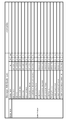
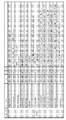
- FIG. 3 is a diagram (part 1) illustrating information necessary for generating DICOM format ultrasonic image data
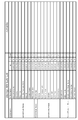
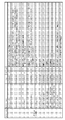
- FIG. 6 is a diagram (part 2) illustrating information necessary for generating DICOM format ultrasonic image data
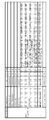
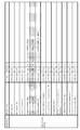
- FIG. 4 is a diagram (part 3) illustrating information necessary for generating DICOM format ultrasonic image data
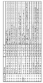
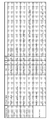
- FIG. 14 is a diagram (part 4) illustrating information necessary for generating DICOM format ultrasonic image data
- FIG. 10 is a diagram (part 5) illustrating information necessary for generating DICOM format ultrasonic image data
- FIG. 11 is a diagram (part 6) illustrating information necessary for generating DICOM format ultrasonic image data
- FIG. 10 is a diagram (part 7) illustrating information necessary for generating DICOM format ultrasonic image data
- FIG. 10 is a diagram (part 8) illustrating information necessary for generating DICOM format ultrasonic image data
- FIG. 9 is a diagram (part 9) illustrating information necessary for generating DICOM format ultrasonic image data
- FIG. 10 is a diagram (part 10) illustrating information necessary for generating DICOM format ultrasonic image data
- FIG. 11 is a diagram (No. 11) illustrating information necessary for generating DICOM format ultrasonic image data
- FIG. 11 is a diagram (No. 11) illustrating information necessary for generating DICOM format ultrasonic image data
- FIG. 11 is a diagram (No. 11) illustrating information necessary for generating DICOM format ultrasonic image data
- FIG. 12 is a diagram (No. 12) illustrating information necessary for generating DICOM format ultrasonic image data; It is a block diagram of the medical system which concerns on 2nd Embodiment. It is the flowchart which showed the recording process of the moving image by the medical system which concerns on 2nd Embodiment, and the transfer process to a DICOM server.
- FIG. 1 is a configuration diagram of a medical system according to the present embodiment.
- a medical system 100 in FIG. 1 includes a video processor 1, an endoscope ultrasonic observation apparatus (hereinafter abbreviated as an ultrasonic observation apparatus) 2, an ultrasonic endoscope 4, and a DICOM server 3.
- an ultrasonic observation apparatus hereinafter abbreviated as an ultrasonic observation apparatus
- an ultrasonic endoscope 4 an ultrasonic endoscope 4
- DICOM server 3 a DICOM server 3.
- the video processor 1 includes a scope connection unit 11, a control unit 12, an image processing unit 14, an image recording unit 16, a storage unit 17, a memory 13, and a communication interface unit (hereinafter abbreviated as a communication I / F unit) 15. And an external video input unit 18 and a network interface unit (abbreviated as a network I / F unit in FIG. 1 and the following) 19.
- the video processor 1 generates endoscopic image data and ultrasonic image data in DICOM format in the medical system 100 of FIG.
- the scope connection unit 11 is a connection interface unit with the ultrasonic endoscope 4 and receives an image signal input from the ultrasonic endoscope 4.
- the ultrasonic endoscope 4 is illustrated in FIG. 1, the present invention is not limited to this, and instead of this, it may be configured by a normal endoscope and an ultrasonic probe.
- the control unit 12 controls each part of the video processor 1 and controls related to the endoscopic inspection of each connected device such as the ultrasonic endoscope 4.
- the control unit 12 receives a release signal from the ultrasonic endoscope 4 via the scope control unit 11, the control unit 12 controls each unit according to the observation mode of the ultrasonic endoscope 4 to generate image data in DICOM format.
- the generated data is transmitted to the DICOM server 3. Details of such processing will be specifically described later.
- the image processing unit 14 When the observation mode is a normal mode (a mode indicating that observation is performed with an endoscope), the image processing unit 14 performs necessary processing on the input image signal, and performs endoscope image data in DICOM format. Get. Information necessary for generating endoscope image data in DICOM format is stored in the memory 13. The image recording unit 16 temporarily records the obtained image data. The video processor 1 communicates with the DICOM server 3 using the DICOM protocol, and the image data recorded in the image recording unit 16 is transmitted to the DICOM server 3 via the network I / F unit 19.
- the external video input unit 18 When the observation mode is an ultrasonic mode (a mode representing observation with an ultrasonic observation apparatus), the external video input unit 18 performs an image signal on which necessary processing has been performed via the ultrasonic observation apparatus 2. Accepts input.
- the ultrasonic observation apparatus 2 In the ultrasonic mode, in the present embodiment, in this embodiment, the ultrasonic observation apparatus 2 communicates with the ultrasonic observation apparatus 2 using a predetermined protocol (general-purpose protocol) different from the DICOM protocol. Information necessary for obtaining DICOM format image data for the ultrasound image is acquired from the observation device 2.
- the storage unit 17 stores an operating system (OS), an application, and the like of the video processor 1.
- the control unit 12 reads out the OS and applications from the storage unit 17, expands and executes them, thereby controlling each unit and system of the video processor 1, generating DICOM format image data and a DICOM server according to the present embodiment.
- the transmission process to 3 is executed.
- the ultrasonic observation apparatus 2 includes an ultrasonic scope / probe connection unit 21, a control unit 22, an image processing unit 24, a storage unit 26, a memory 23, and a communication interface unit (hereinafter abbreviated as a communication I / F unit in FIG. 1 and below). 25 and a video output unit 27.
- the ultrasonic observation device 2 When the observation mode in the endoscopic examination is set to the ultrasonic mode, the ultrasonic observation device 2 performs necessary processing on the image signal input from the ultrasonic endoscope 4 and sends a signal to the video processor 1. Output.
- the ultrasound observation apparatus 2 transmits information necessary for generating DICOM format ultrasound image data to the video processor 1.
- the ultrasonic scope / probe connection unit 21 is a connection interface unit with the ultrasonic endoscope 4 and receives an image signal input from the ultrasonic endoscope 4.
- the control unit 22 controls the respective units constituting the ultrasonic observation apparatus 2. Are controlled to generate ultrasonic image data.
- the image processing unit 24 performs necessary processing on the image signal input via the ultrasonic scope / probe connection unit 21 to generate ultrasonic image data. Since the DICOM format image data is generated by the video processor 1, the generated image data and predetermined information corresponding thereto are transmitted to the video processor 1 via the video output unit 27 and the communication I / F unit 25, respectively. Is done. Details thereof will be described later.
- the storage unit 26 stores an operating system (OS), an application, and the like of the ultrasound observation apparatus 2.
- the control unit 22 reads out the OS and application from the storage unit 26, expands and executes the OS and the application, thereby controlling each unit of the ultrasonic observation apparatus 2.
- OS operating system
- the control unit 22 reads out the OS and application from the storage unit 26, expands and executes the OS and the application, thereby controlling each unit of the ultrasonic observation apparatus 2.
- a DICOM type ultrasonic wave Information necessary for generating image data by the video processor 1 and processing for transmitting image data to the video processor 1 are performed.
- the memory 23 stores information necessary to generate DICOM format ultrasonic image data.
- the video processor 1 generates DICOM format data from the obtained images depending on whether the observation mode is set to the normal mode or the ultrasonic mode in the endoscopy, Transmit to the DICOM server 3.
- the DICOM server 3 stores data received via the network interface unit (network I / F unit in FIG. 1) 31.
- the video processor 1 receives necessary information and image data subjected to image processing from the ultrasonic observation apparatus 2, and based on this, DICOM Generate ultrasound image data in the format. This will be specifically described with reference to a flowchart and the like.
- FIG. 2 is a flowchart showing image recording and transfer processing to the DICOM server 3 by the medical system 100 according to the present embodiment.
- the video processor 1 When starting one endoscopic examination, the video processor 1 generates identification information such as ID (Identification) for identifying the examination, and sets information for identifying a modality (medical device) used in the examination. These pieces of information are held in the memory 13.
- ID Identification
- modality medical device
- -Inspection is started when information for identifying inspection and modality to be used are set. Thereafter, a user such as a doctor observes the body cavity of the subject using the ultrasonic endoscope 4 while appropriately switching the observation mode between the normal mode and the ultrasonic mode. When a user finds a suspicious portion or the like, he / she operates an operation button or the like at hand. With this operation, a release signal is generated from the ultrasonic endoscope 4 and input to the video processor 1. In step S1, the control unit 12 of the video processor 1 recognizes the release operation based on the signal.
- step S2 the control unit 12 of the video processor 1 issues a release ID for identifying the release. Thereafter, in step S3, when the control unit 12 recognizes that the user has performed the freeze operation based on the freeze signal input from the ultrasonic endoscope 4, the process proceeds to the determination in step S4.
- step S4 the control unit 12 determines whether or not the ultrasound observation apparatus 2 is connected to the medical system 100 and the observation mode is set to the ultrasound mode.
- the process proceeds to step S8. Otherwise, the process proceeds to step S5.
- step S5 an endoscope image in DICOM format is recorded and transferred to the DICOM server 3.
- the control unit 12 of the video processor 1 stores the normal visible light endoscopic image data obtained by performing necessary processing in the image processing unit 14 in the memory 13.
- Endoscopic image data in DICOM format is generated from the information and recorded in the image recording unit 16.
- step S6 when the control unit 12 recognizes that the freeze has been released, in step S7, the controller 12 reads out the data of the endoscope image in the DICOM format from the image recording unit 16 and transmits it to the DICOM server 3.
- the series of processes in FIG. 2 ends. Endoscopic image recording and transfer processing is the same as in the conventional case where the modality used is an endoscope.
- step S8 and subsequent steps recording of DICOM format ultrasonic images and transfer to the DICOM server 3 are performed.
- the control unit 12 of the video processor 1 transmits the release ID issued in step S2 to the ultrasound observation apparatus 2 via the communication I / F unit 15.
- step S ⁇ b> 9 when receiving the release ID via the communication I / F unit 25, the control unit 22 of the ultrasound observation apparatus 2 reads out information necessary for generating DICOM format ultrasound image data from the memory 23. .
- the control unit 22 associates the read information with the received release ID and transmits the information to the video processor 1 via the communication I / F unit 25.
- FIGS. 3A to 3L are diagrams illustrating information necessary for generating DICOM format ultrasonic image data.
- the data structure of information attached to image data is defined, and in accordance with this definition, the video processor 1 adds information (metadata) defined for each of the endoscopic image and the ultrasound image. Then, DICOM format image data is generated.
- the difference between the endoscope image data and the ultrasound image data is shown by shading in FIGS. 3A to 3L.
- the other items that are not shaded are the same as the information added to the data of the endoscopic image, and the video processor 1 uses the information held in the memory 13 of its own device.
- the video processor 1 displays the communication I / F unit.
- the information is received via 15.
- the ultrasonic observation apparatus 2 transmits the ultrasonic image data obtained by performing necessary processing in the image processing unit 24 from the video output unit 27 to the video processor 1.
- the video processor 1 receives the image data via the external video input unit 18.
- step S9 from the viewpoint of reducing the amount of communication, information transmitted from the ultrasound observation apparatus 2 to the video processor 1 via the communication I / F unit 25 is displayed in the DICOM format as described above. Only the difference from the mirror image (shaded items in FIGS. 3A to 3L) is shown. However, the present invention is not limited to this. For example, all items in FIGS. 3A to 3L may be transmitted.
- step S ⁇ b> 10 the control unit 12 of the video processor 1 receives the ultrasonic image being input through the external video input unit 18 and inputting PinP (Picture in Picture) and the information received through at least the communication I / F unit 15.
- PinP Pin in Picture
- the DICOM format ultrasonic image data is generated by adding metadata shown in FIGS. 3A to 3L to image data (pixel data). In the embodiment, information that is not held in the video processor 1 is described. Obtained from the ultrasonic observation apparatus 2.
- the generated DICOM format ultrasonic image data is recorded in the image recording unit 16 in association with the release ID issued in step S2.
- step S11 and step S12 the process similar to step S6 and step S7 is implemented, respectively. That is, in step S11, when the control unit 12 recognizes that the freeze has been released, in step S12, the control unit 12 reads DICOM format image data from the image recording unit 16, transmits the data to the DICOM server 3, and transmits the data.
- step S11 when the control unit 12 recognizes that the freeze has been released, in step S12, the control unit 12 reads DICOM format image data from the image recording unit 16, transmits the data to the DICOM server 3, and transmits the data.
- DICOM format image data is obtained for both the endoscopic image and the ultrasonic image according to the observation mode when the release operation is performed in one examination. It can be generated and registered in the DICOM server 3.
- DICOM format image data is generated for an endoscopic image or an ultrasound image acquired according to an observation mode. And can be registered in the DICOM server 3.
- one modality endoscope in the above example
- the other modality an ultrasonic device in the example
- FIG. 3A to FIG. 3A added to the ultrasonic image when creating the report.
- information indicated by shading can also be used.
- x0, y0, x1, and y1 representing the position coordinates of each vertex of the ultrasound image represented by the rectangle are respectively attribute names (Attribute Name).
- (Region Location Min x0 ") ((* 1) in FIG. 3E).
- physical units in the x and y directions (same as “Physical Units X (Y) Direction”), increments thereof (same as “Physical Delta X (Y)”), and reference position coordinates x0, y0 (same as “Reference”).
- Pixel x0 (y0) ) is also included ((* 2) in FIG. 3F).
- the ultrasonic observation apparatus 2 can perform such processing.
- the ultrasound observation apparatus 2 receives a release or freeze operation by the user, and issues a release ID and transmits it to the video processor 1.
- the video processor 1 that has received the release ID reads information necessary for generating an endoscope image in DICOM format from the memory 13 of its own device, and transmits the information in association with the release ID.
- the ultrasound observation apparatus 2 associates image data received from the video processor 1 with information necessary for generating a DICOM format image, and generates DICOM format endoscope image data. Transmit to the DICOM server 3. Even if comprised in this way, the effect similar to the structure of FIG. 2 is acquired.
- each of the three or more medical devices can acquire an image and generate an image in DICOM format.
- a plurality of types of medical devices are configured to be able to communicate release IDs and image data to medical devices that are connected to the DICOM server 3 and generate and transfer DICOM format images.
- the video processor 1 issues a release ID according to the release operation, and a medical device corresponding to the observation mode.
- the release ID is sent to.
- the operation in the medical device that has received the release ID and the operation in the video processor 1 after receiving the necessary information associated with the release ID are the same as in the case of the two-unit configuration described above. In this way, even with the configuration of three or more units, the same effect as in the case of the two-unit configuration illustrated in FIG. 2 is obtained.
- a DICOM format image is generated for a still image.
- the present embodiment differs in that a DICOM format moving image is generated for a moving image.
- FIG. 4 is a configuration diagram of the medical system 100 according to the present embodiment. Compared with the block diagram of the first embodiment shown in FIG. 1, the video processor 1 in FIG. 1 records the DICOM format image generated in the image recording unit 16, whereas in FIG. The difference is that a moving image in DICOM format is recorded in the moving image recording unit 161.
- the endoscope moving image is captured when the observation mode is set to the normal mode, and the ultrasonic moving image is captured when the observation mode is set to the ultrasonic mode.
- DICOM format moving image data for the corresponding modality is generated, and the generated DICOM format moving image data is registered in the DICOM server 3. This method will be specifically described with reference to a flowchart.
- FIG. 5 is a flowchart showing the moving image recording and transfer processing to the DICOM server 3 by the medical system 100 according to the present embodiment. Similar to the case of recording and transferring the still image in FIG. 2, the video processor 1 generates identification information for identifying the examination when starting one endoscopic examination, and also uses the modality used in the examination. Is set, and the information is stored in the memory 13. In the configuration of FIG. 4, the “endoscope” is set to the modality to be used.
- step S ⁇ b> 21 the control unit 12 of the video processor 1 recognizes an instruction to start recording a moving image based on the signal.
- step S22 the control unit 12 of the video processor 1 issues a management ID for managing moving images. Then, the process proceeds to the determination in step S23.
- the determination in step S23 is the same as that in step S4 in FIG.
- the process proceeds to step S27, and otherwise, the process proceeds to step S24.
- step S24 an endoscope moving image in DICOM format is recorded and transferred to the DICOM server 3.
- the control unit 12 of the video processor 1 stores the data of the normal visible light endoscope moving image obtained by performing the necessary processing in the image processing unit 14 in the memory 13.
- the endoscope moving image data in DICOM format is generated from the information to be recorded and recorded in the moving image recording unit 161.
- the control unit 12 determines whether or not a signal instructing to end the recording of the moving image has been received from the ultrasonic endoscope 4, and the DICOM format in step S24 is received until the signal is received. Continue the process of recording the endoscopic video.
- step S ⁇ b> 26 the control unit 12 reads the data of the endoscope moving image in the DICOM format from the moving image recording unit 16 and transmits it to the DICOM server 3.
- the series of processes in FIG. 5 ends.
- the process of recording and transferring the endoscope moving image is the same as that in the conventional case where the modality to be used is an endoscope.
- step S27 and subsequent steps recording of DICOM format ultrasonic moving images and transfer to the DICOM server 3 are performed.
- the control unit 12 of the video processor 1 transmits the management ID issued in step S22 to the ultrasonic observation apparatus 2 via the communication I / F unit 15.
- the control unit 22 of the ultrasonic observation apparatus 2 receives the management ID via the communication I / F unit 25, the control unit 22 stores the management ID in the memory 23.
- the control unit 22 of the ultrasonic observation apparatus 2 causes the video output unit 27 to transmit the ultrasonic moving image data obtained by performing the necessary processing in the image processing unit 24 to the video processor 1.
- the video processor 1 receives the moving image data via the external video input unit 18.
- step S28 the control unit 12 of the video processor 1 records the ultrasonic moving image during PinP input received via the external video input unit 18 in the moving image recording unit 161. Then, in step S29, the control unit 12 determines whether or not a signal instructing to end the recording of the moving image has been received from the ultrasonic endoscope 4, and the processing in step S28 is continued until the signal is received. The process of recording the sonic moving image in the moving image recording unit 161 is continued. When the signal is received, the process proceeds to step S30.
- step S30 the control unit 22 of the ultrasonic observation apparatus 2 reads out information necessary for generating the DICOM format ultrasonic moving image data from the memory 23 by the video processor 1.
- the control unit 22 associates the read information with the received management ID and transmits the information to the video processor 1 via the communication I / F unit 25.
- the video processor 1 receives the information via the communication I / F unit 15.
- step S31 the control unit 12 of the video processor 1 associates the moving image data recorded in the moving image recording unit 161 in step S28 with the information received in step S30, and generates DICOM format ultrasonic moving image data. Then, this is recorded in the moving image recording unit 161 again.
- step S ⁇ b> 32 the control unit 12 reads out DICOM format ultrasonic moving image data from the moving image recording unit 161 and transmits the data to the DICOM server 3. When the transmission process ends, the series of processes in FIG. 5 ends.
- the ultrasound observation apparatus 2 can acquire the necessary information from the video processor 1 to generate a DICOM-format endoscopic video, and can be applied to a medical system including three or more medical apparatuses. This is the same as in the first embodiment.
- the present invention is not limited to the above-described embodiments as they are, and can be embodied by modifying the constituent elements without departing from the scope of the invention in the implementation stage.
- various inventions can be formed by appropriately combining a plurality of constituent elements disclosed in the embodiment. For example, all the constituent elements shown in the embodiments may be appropriately combined. Furthermore, constituent elements over different embodiments may be appropriately combined. It goes without saying that various modifications and applications are possible without departing from the spirit of the invention.
Landscapes
- Health & Medical Sciences (AREA)
- Engineering & Computer Science (AREA)
- Public Health (AREA)
- Life Sciences & Earth Sciences (AREA)
- General Health & Medical Sciences (AREA)
- Medical Informatics (AREA)
- Radiology & Medical Imaging (AREA)
- Nuclear Medicine, Radiotherapy & Molecular Imaging (AREA)
- Epidemiology (AREA)
- Primary Health Care (AREA)
- Biomedical Technology (AREA)
- Surgery (AREA)
- Veterinary Medicine (AREA)
- Heart & Thoracic Surgery (AREA)
- Animal Behavior & Ethology (AREA)
- Biophysics (AREA)
- Physics & Mathematics (AREA)
- Pathology (AREA)
- Molecular Biology (AREA)
- Computer Networks & Wireless Communication (AREA)
- Business, Economics & Management (AREA)
- General Business, Economics & Management (AREA)
- Ultra Sonic Daignosis Equipment (AREA)
- Measuring And Recording Apparatus For Diagnosis (AREA)
- Endoscopes (AREA)
- Optics & Photonics (AREA)
Abstract
ビデオプロセッサ1及び超音波観測装置2は、それぞれの画像についてDICOM形式のデータを生成するときに付加される第1及び第2の付加情報を記憶する。通信I/F部15は、ビデオプロセッサ1と超音波観測装置2との間で超音波画像と第2の付加情報の一部または全てを汎用プロトコルで定められるネットワークを介して通信する。制御部12は、少なくとも通信I/F部15を介して受信した情報に基づき超音波画像についてのDICOM形式のデータを生成する。ネットワークI/F部19は、DICOMサーバ3との間で、生成された超音波画像についてのDICOM形式のデータをDICOMプロトコルで定められるネットワークを介して通信する。
Description
本発明は、検査等にて医用画像を取得する複数の医療装置と医用画像を格納するサーバとを有し、医療装置とサーバとの間で医療画像を送受する医療通信システムに関し、特に、DICOM(Digital Imaging and Communication in Medicine)規格対応の医療通信システムに関する。
近年、医療の場においては、内視鏡装置等の医療装置にて被検体を撮影して取得した医用画像については、DICOM規格対応のシステムにて管理する傾向にある。DICOM規格対応のシステムでは、医療装置にて取得した医用画像よりDICOM形式のデータを生成し、これをDICOM対応のサーバに保存しておく。
ここで、従来より、1回の内視鏡検査において、通常の内視鏡だけでなく超音波内視鏡の画像等の複数の撮影装置を使用する(マルチモダリティ)ユースケースも存在している。このようなユースケースを想定したDICOM規格対応のシステムについても検討されており、公知の技術となっている(例えば、特許文献1)。
現時点では、DICOMプロトコル規格のネットワーク上におけるDICOMサーバと通信して行われる検査は、1検査につき、1つのモダリティしか使用できない、という制限が存在する。このため、1検査で複数のモダリティを使用する場合であっても、DICOMサーバに格納できるデータは、指定したモダリティについての形式に限られてしまうこととなる。
DICOM規格では、内視鏡画像及び超音波画像のそれぞれの画像データに付加される情報が規定されている。しかし、上記の1検査につき1つのモダリティしか使用できないという制約の下では、1回の内視鏡検査において取得した超音波画像に対しても、内視鏡画像に付加される情報と同様の情報しか付加することができない。
本発明は、現在のDICOM規格の下、マルチモダリティのユースケースにおいても各モダリティ(医療装置)に応じたDICOM形式のデータを生成してDICOMサーバに登録することを可能とする技術を提供することを目的とする。
本発明の一態様によれば、被写体にかかわる第1の情報についてDICOM形式のデータを生成するときに前記第1の情報に付加する第1の付加情報を記憶する第1の医療装置と、DICOMプロトコルで定められるネットワークを介して、前記第1の医療装置との間で通信可能に形成されるDICOMサーバと、前記被写体にかかわる第2の情報についてDICOM形式のデータを生成するときに前記第2の情報に付加する第2の付加情報を記憶する第2の医療装置と、前記第1の医療装置と前記第2の医療装置との間で、前記第2の情報と、前記第2の記憶装置に記憶されている前記第2の付加情報の一部または全てを、前記DICOMプロトコルとは異なる所定のプロトコルで定められるネットワークを介して通信する第1の通信部と、前記第1の医療装置に備えられ、少なくとも前記第1の通信部を介して受信した情報に基づいて、前記第2の情報についてのDICOM形式のデータを生成するDICOM情報生成部と、前記第1の医療装置に備えられ、前記DICOMサーバとの間で、前記DICOM情報生成部により生成された前記第2の情報についてのDICOM形式のデータを、前記DICOMプロトコルで定められるネットワークを介して通信する第2の通信部と、を備えることを特徴とする。
本発明によれば、現在のDICOM規格の下、マルチモダリティのユースケースにおいても各モダリティに応じたDICOM形式のデータを生成してDICOMサーバに登録することが可能となる。
以下、本発明の実施の形態について、図面を参照して詳細に説明する。
<第1の実施形態>
図1は、本実施形態に係る医療システムの構成図である。図1の医療システム100は、ビデオプロセッサ1、内視鏡用超音波観測装置(以下においては超音波観測装置と略記)2、超音波内視鏡4及びDICOMサーバ3を有する。医療システム100は、超音波内視鏡4にて被検体より得られる画像信号に対して必要な処理を施すと、DICOM形式のデータ構造を有するデータを生成し、これをDICOMサーバ3に登録する。
<第1の実施形態>
図1は、本実施形態に係る医療システムの構成図である。図1の医療システム100は、ビデオプロセッサ1、内視鏡用超音波観測装置(以下においては超音波観測装置と略記)2、超音波内視鏡4及びDICOMサーバ3を有する。医療システム100は、超音波内視鏡4にて被検体より得られる画像信号に対して必要な処理を施すと、DICOM形式のデータ構造を有するデータを生成し、これをDICOMサーバ3に登録する。
ビデオプロセッサ1は、スコープ接続部11、制御部12、画像処理部14、画像記録部16、記憶部17、メモリ13、通信インタフェース部(図1及び以下においては通信I/F部と略記)15、外部映像入力部18及びネットワークインタフェース部(図1及び以下においてはネットワークI/F部と略記)19を有する。ビデオプロセッサ1は、図1の医療システム100において、DICOM形式の内視鏡画像データ及び超音波画像データを生成する。
ビデオプロセッサ1のうち、スコープ接続部11は、超音波内視鏡4との接続インタフェース部であり、超音波内視鏡4から入力される画像信号を受け付ける。なお、図1においては超音波内視鏡4を記載しているが、これには限定されず、この代わりに、通常の内視鏡と超音波プローブとから構成されてもよい。
制御部12は、ビデオプロセッサ1を構成する各部の制御や、超音波内視鏡4等の接続されている各機器の内視鏡検査に関わる制御を行う。制御部12は、スコープ制御部11を介して超音波内視鏡4からのレリーズ信号を受け付けると、超音波内視鏡4の観察モードに応じて各部を制御してDICOM形式の画像データを生成させ、生成したデータをDICOMサーバ3に送信する処理を実施する。かかる処理の詳細については、後に具体的に説明することとする。
画像処理部14は、上記観察モードが通常モード(内視鏡で観察を行うことを表すモード)であるときは、入力された画像信号に必要な処理を施し、DICOM形式の内視鏡画像データを得る。DICOM形式の内視鏡画像データを生成するために必要な情報は、メモリ13に格納されている。画像記録部16は、得られた画像データを一時的に記録する。ビデオプロセッサ1は、DICOMプロトコルを用いてDICOMサーバ3と通信を行い、画像記録部16に記録された画像データは、ネットワークI/F部19を介して、DICOMサーバ3に送信される。
外部映像入力部18は、上記観察モードが超音波モード(超音波観測装置で観察を行うことを表すモード)であるときは、超音波観測装置2を介して必要な処理の施された画像信号の入力を受け付ける。超音波モードにおいては、これとともに、本実施形態においては、通信I/F部15を介して超音波観測装置2とDICOMプロトコルと異なる所定のプロトコル(汎用プロトコル)を用いて通信を行い、超音波観測装置2から、超音波画像についてDICOM形式の画像データを得るために必要な情報を取得する。
記憶部17には、ビデオプロセッサ1のオペレーティングシステム(OS)やアプリ等が記憶されている。制御部12は、記憶部17からOSやアプリを読み出してこれを展開して実行することにより、ビデオプロセッサ1の各部やシステムの制御、本実施形態に係るDICOM形式の画像データの生成及びDICOMサーバ3への送信処理等を実施する。
超音波観測装置2は、超音波スコープ・プローブ接続部21、制御部22、画像処理部24、記憶部26、メモリ23、通信インタフェース部(図1及び以下においては通信I/F部と略記)25及び映像出力部27を有する。超音波観測装置2は、内視鏡検査における観察モードが超音波モードに設定されているとき、超音波内視鏡4から入力される画像信号に必要な処理を施してビデオプロセッサ1に信号を出力する。これとともに、本実施形態においては、超音波観測装置2は、DICOM形式の超音波画像データを生成するために必要な情報をビデオプロセッサ1に送信する。
超音波スコープ・プローブ接続部21は、超音波内視鏡4との接続インタフェース部であり、超音波内視鏡4から入力される画像信号を受け付ける。
制御部22は、超音波観測装置2を構成する各部の制御を行い、超音波スコープ・プローブ接続部21を介して超音波内視鏡4から画像信号が入力されると、画像処理部24等の各部を制御して超音波画像データを生成させる。
制御部22は、超音波観測装置2を構成する各部の制御を行い、超音波スコープ・プローブ接続部21を介して超音波内視鏡4から画像信号が入力されると、画像処理部24等の各部を制御して超音波画像データを生成させる。
画像処理部24は、上記のとおり、超音波スコープ・プローブ接続部21を介して入力された画像信号に対して必要な処理を施し、超音波画像データを生成する。ビデオプロセッサ1にてDICOM形式の画像データを生成するため、生成した画像データ及びこれに対応する所定の情報については、それぞれ映像出力部27及び通信I/F部25を介してビデオプロセッサ1に送信される。その詳細については、後に詳しく説明する。
記憶部26には、超音波観測装置2のオペレーティングシステム(OS)やアプリ等が記憶されている。制御部22は、記憶部26からOSやアプリを読み出してこれを展開して実行することにより、超音波観測装置2の各部の制御を行い、本実施形態に関しては、例えば、DICOM形式の超音波画像データをビデオプロセッサ1にて生成するために必要な情報や画像データのビデオプロセッサ1への送信処理等を実施する。メモリ23には、DICOM形式の超音波画像データを生成するために必要な情報が格納されている。
このように、ビデオプロセッサ1は、内視鏡検査において観察モードが通常モードまたは超音波モードのいずれに設定されているかに応じて、それぞれ得られた画像からDICOM形式のデータを生成し、これをDICOMサーバ3に送信する。DICOMサーバ3は、ネットワークインタフェース部(図1においてはネットワークI/F部)31を介して受信したデータを格納する。
ここで、観察モードが超音波モードに設定されているときは、ビデオプロセッサ1は、超音波観測装置2から必要な情報と画像処理を施した画像データとを受信して、これに基づき、DICOM形式の超音波画像データを生成する。これについて、フローチャート等を参照して、具体的に説明する。
図2は、本実施形態に係る医療システム100による画像の記録及びDICOMサーバ3への転送処理を示したフローチャートである。
ビデオプロセッサ1は、1件の内視鏡検査を開始するに際して、検査を識別するID(Identification)等の識別情報を生成し、また、検査において使用するモダリティ(医療装置)を識別する情報を設定し、これらの情報をメモリ13に保持する。図1の構成においては、「内視鏡」が、使用するモダリティに設定される。
ビデオプロセッサ1は、1件の内視鏡検査を開始するに際して、検査を識別するID(Identification)等の識別情報を生成し、また、検査において使用するモダリティ(医療装置)を識別する情報を設定し、これらの情報をメモリ13に保持する。図1の構成においては、「内視鏡」が、使用するモダリティに設定される。
検査を識別する情報及び使用するモダリティが設定されると、検査が開始する。以後は、医師等のユーザは、通常モードと超音波モードとの間で観察モードを適宜切り替えつつ、超音波内視鏡4を用いて被検体の体腔内を観察する。ユーザは、病変の疑いのある箇所等を発見した場合には、手元の操作ボタン等を操作する。当該操作により、レリーズ信号が超音波内視鏡4から発せられ、ビデオプロセッサ1に入力される。ステップS1では、ビデオプロセッサ1の制御部12が、当該信号により、レリーズ操作を認識する。
ステップS2では、ビデオプロセッサ1の制御部12は、レリーズを識別するレリーズIDを発行する。その後、ステップS3で、制御部12は、超音波内視鏡4から入力されるフリーズ信号によってユーザによりフリーズ操作がなされたことを認識すると、ステップS4の判定へと処理を移行させる。
ステップS4では、制御部12は、超音波観測装置2が医療システム100に接続されており、且つ観察モードが超音波モードに設定されているか否かを判定する。超音波観測装置2が医療システム100に接続され、且つ観察モードが超音波モードであるときは、ステップS8へと処理を移行させ、それ以外の場合は、ステップS5へと処理を移行させる。
ステップS5以降では、DICOM形式の内視鏡画像が記録され、DICOMサーバ3に転送される。具体的には、まず、ステップS5で、ビデオプロセッサ1の制御部12は、画像処理部14にて必要な処理を施して得られる通常可視光の内視鏡画像のデータとメモリ13に保持する情報からDICOM形式の内視鏡画像データを生成し、画像記録部16に記録する。ステップS6で、制御部12は、フリーズが解除されたことを認識すると、ステップS7で、画像記録部16からDICOM形式の内視鏡画像のデータを読み出して、DICOMサーバ3に向けて送信する。送信処理を終えると、図2の一連の処理を終了する。内視鏡画像の記録及び転送処理については、使用するモダリティを内視鏡とする場合の従来におけるそれと同様である。
一方、ステップS8以降では、DICOM形式の超音波画像の記録及びDICOMサーバ3への転送が行われる。具体的には、まず、ステップS8で、ビデオプロセッサ1の制御部12は、通信I/F部15を介して超音波観測装置2に向けてステップS2で発行したレリーズIDを送信する。ステップS9で、超音波観測装置2の制御部22は、通信I/F部25を介してレリーズIDを受信すると、DICOM形式の超音波画像データを生成するために必要な情報をメモリ23から読み出す。制御部22は、読み出した情報を受信したレリーズIDに紐付けて、通信I/F部25を介してビデオプロセッサ1に向けて送信する。
図3A~図3Lは、DICOM形式の超音波画像データを生成するために必要な情報を例示する図である。
DICOM規定では、画像データに付す情報のデータ構造が定義されており、ビデオプロセッサ1は、この定義にしたがって、内視鏡画像及び超音波画像にそれぞれに定義されている情報(メタデータ)を付加して、DICOM形式の画像データを生成する。
DICOM規定では、画像データに付す情報のデータ構造が定義されており、ビデオプロセッサ1は、この定義にしたがって、内視鏡画像及び超音波画像にそれぞれに定義されている情報(メタデータ)を付加して、DICOM形式の画像データを生成する。
なお、DICOM形式の画像データのうち、内視鏡画像データ及び超音波画像データの差分を、図3A~図3Lにおいては網掛けで示す。網掛けのされていない他の項目については、内視鏡画像のデータに付される情報と同様であり、ビデオプロセッサ1は、自装置のメモリ13に保持している情報を利用する。
図2の説明に戻ると、ステップS9で、超音波観測装置2の通信I/F部25が図3A~図3Lの網掛けで示す情報を送信すると、ビデオプロセッサ1は、通信I/F部15を介して当該情報を受信する。これとともに、超音波観測装置2は、映像出力部27から画像処理部24で必要な処理を施して得られた超音波画像データを、ビデオプロセッサ1に向けて送信する。ビデオプロセッサ1は、外部映像入力部18を介して当該画像データを受信する。
なお、ステップS9では、通信量の削減の観点より、超音波観測装置2が通信I/F部25を介してビデオプロセッサ1に向けて送信する情報については、上記のとおり、DICOM形式の内視鏡画像との差分箇所(図3A~図3Lの網掛けの項目)のみとしている。しかし、これに限定されるものではなく、例えば、図3A~図3Lの全項目を送信することとしてもよい。
ステップS10で、ビデオプロセッサ1の制御部12は、外部映像入力部18を介して受信したPinP(Picture in Picture)入力中の超音波画像と、少なくとも通信I/F部15を介して受信した情報とを用いて、DICOM形式の超音波画像データを生成する。上記のとおり、DICOM形式の超音波画像データは、画像データ(画素データ)に図3A~図3Lに示すメタデータを付すことにより生成され、実施例では、ビデオプロセッサ1においては保持しない情報については超音波観測装置2から取得することとしている。生成したDICOM形式の超音波画像データは、ステップS2で発行したレリーズIDと対応付けて、画像記録部16に記録される。
ステップS11及びステップS12については、それぞれステップS6及びステップS7と同様の処理を実施する。すなわち、ステップS11で、制御部12は、フリーズが解除されたことを認識すると、ステップS12で、画像記録部16からDICOM形式の画像のデータを読み出して、DICOMサーバ3に向けて送信し、送信処理を終えると、図2の一連の処理を終了する。
先述のとおり、図2に示す一連の処理は、検査を識別する情報及び使用するモダリティが設定されて1回の内視鏡検査が開始すると、その後のユーザのレリーズ操作ごとに実施される。すなわち、本実施形態に係る医療システム100によれば、1回の検査において、レリーズ操作がなされたときの観察モードに応じ、内視鏡画像及び超音波画像の両方についてそれぞれDICOM形式の画像データを生成し、DICOMサーバ3に登録することが可能である。
以上説明したように、本実施形態に係る医療システム100によれば、マルチモダリティのユースケースにおいては、観察モードに応じて取得される内視鏡画像または超音波画像についてDICOM形式の画像データを生成し、DICOMサーバ3に登録することができる。DICOM規定により、1回の検査では、使用するモダリティとしては一のモダリティ(上記の設例では内視鏡)が設定されるが、他方のモダリティ(設例では超音波装置)についても、その他方のモダリティ側から必要な情報を取得する。取得した情報を用いることにより、使用するモダリティとして設定されていないモダリティで取得した画像についても、DICOM形式のデータを生成することが可能となる。
DICOMサーバ3に登録された内視鏡検査に関するデータは、検査後のレポート作成等において用いられる。このとき、超音波画像についても内視鏡画像と同様にDICOM形式でDICOMサーバ3に登録されていることにより、ユーザにとっては、レポート作成の際に、超音波画像に付加されている図3A~図3Lにおいては網掛けで示す情報についても利用することが可能となる。
例えば、図3E及び図3Fに示すモジュール「US Region Calibration Module」には、長方形で表される超音波画像の各頂点の位置座標を表すx0、y0、x1、y1が、それぞれ属性名(Attribute Nameの「Region Location Min x0」等)として含まれる(図3Eの(*1))。また、x方向及びy方向の物理単位(同「Physical Units X(Y) Direction」)、及びその増分(同「Physical Delta X(Y)」)、基準となる位置座標x0、y0(同「Reference Pixel x0(y0)」)も含まれている(図3Fの(*2))。これらの情報により、ユーザは、例えば画像中の病変の疑いのある箇所等を特定してレポートを作成すること等が可能となる。
なお、図1においては、ビデオプロセッサ1において、1検査で得られる画像は観察モードに応じたDICOM形式の画像を生成する構成を示しているが、これに限定されるものではない。例えば、超音波観測装置2にてかかる処理を実施する構成とすることもできる。この場合は、超音波観測装置2がユーザによるレリーズやフリーズの操作を受け付けて、レリーズIDの発行及びビデオプロセッサ1への送信を実施する。レリーズIDを受信したビデオプロセッサ1は、DICOM形式の内視鏡画像の生成に必要な情報を、自装置のメモリ13から読み出して、レリーズIDに紐付けて送信する。超音波観測装置2は、レリーズIDに基づき、ビデオプロセッサ1から受信する画像データとDICOM形式の画像の生成に必要な情報とを対応付けて、DICOM形式の内視鏡画像のデータを生成し、DICOMサーバ3に送信する。このように構成しても、図2の構成と同様の効果を得る。
更には、3台以上の医療装置のそれぞれが画像を取得し、それぞれDICOM形式の画像を生成することができるよう医療システムを構成することもできる。この場合は、DICOMサーバ3に接続され、DICOM形式の画像の生成及び転送を行う医療装置に対し、複数の種類の医療装置がレリーズID及び画像データを通信可能に構成される。例えばビデオプロセッサ1がDICOMサーバ3に接続されてDICOM形式の画像の生成及び転送を行う構成の場合、ビデオプロセッサ1は、レリーズの操作にしたがって、レリーズIDを発行し、観察モードに応じた医療装置に向けてレリーズIDを送信する。レリーズIDを受信した医療装置における動作、及びレリーズIDと紐付けて必要な情報を受信した後のビデオプロセッサ1における動作については、上記の2台構成の場合と同様である。このように、3台以上の構成であっても、図2に例示する2台構成の場合と同様の効果を得る。
<第2の実施形態>
上記の第1の実施形態では、静止画像についてDICOM形式の画像を生成している。これに対し、本実施形態では、動画像についてDICOM形式の動画像を生成する点で異なる。
上記の第1の実施形態では、静止画像についてDICOM形式の画像を生成している。これに対し、本実施形態では、動画像についてDICOM形式の動画像を生成する点で異なる。
以下に、本実施形態に係る医療システムについて、第1の実施形態と異なる点を中心に説明する。
図4は、本実施形態に係る医療システム100の構成図である。図1に示す第1の実施形態についての構成図と比較すると、図1のビデオプロセッサ1においては画像記録部16に生成したDICOM形式の画像を記録していたのに対し、図4のそれでは、動画記録部161にDICOM形式の動画像を記録する点で異なる。
図4は、本実施形態に係る医療システム100の構成図である。図1に示す第1の実施形態についての構成図と比較すると、図1のビデオプロセッサ1においては画像記録部16に生成したDICOM形式の画像を記録していたのに対し、図4のそれでは、動画記録部161にDICOM形式の動画像を記録する点で異なる。
本実施形態に係る医療システム100では、観察モードが通常モードに設定されているときは、内視鏡動画が、超音波モードに設定されているときは、超音波動画が取り込まれる。設定されている観察モードに応じて、対応するモダリティについてのDICOM形式の動画データを生成し、DICOMサーバ3に生成したDICOM形式の動画データを登録する。この方法について、フローチャートを参照して、具体的に説明する。
図5は、本実施形態に係る医療システム100による動画像の記録及びDICOMサーバ3への転送処理を示したフローチャートである。
ビデオプロセッサ1は、図2の静止画像の記録及び転送を行う場合と同様に、1件の内視鏡検査を開始するに際し、検査を識別する識別情報を生成し、また、検査で使用するモダリティを識別する情報を設定して、これらの情報をメモリ13に保持する。図4の構成においては、「内視鏡」が、使用するモダリティに設定される。
ビデオプロセッサ1は、図2の静止画像の記録及び転送を行う場合と同様に、1件の内視鏡検査を開始するに際し、検査を識別する識別情報を生成し、また、検査で使用するモダリティを識別する情報を設定して、これらの情報をメモリ13に保持する。図4の構成においては、「内視鏡」が、使用するモダリティに設定される。
検査を識別する情報及び使用するモダリティが設定されると、検査が開始する。以後は、ユーザは、通常モードと超音波モードとの間で観察モードを適宜切り替えつつ、超音波内視鏡4を用いて被検体の体腔内を観察する。ユーザは、病変の疑いのある箇所等を発見した場合に、動画像の記録を開始することを、手元の操作ボタン等の操作により指示する。当該操作により、動画像の記録を開始する旨を指示する信号が超音波内視鏡4から発せられ、ビデオプロセッサ1に入力される。ステップS21では、ビデオプロセッサ1の制御部12が、当該信号により、動画像の記録を開始する旨の指示を認識する。
ステップS22では、ビデオプロセッサ1の制御部12は、動画を管理するための管理IDを発行する。そして、ステップS23の判定へと処理を移行させる。
ステップS23の判定は、図2のステップS4と同様の判定を行う。超音波観測装置2が医療システム100に接続され、且つ観察モードが超音波モードであるときは、ステップS27へと処理を移行させ、それ以外の場合は、ステップS24へと処理を移行させる。
ステップS23の判定は、図2のステップS4と同様の判定を行う。超音波観測装置2が医療システム100に接続され、且つ観察モードが超音波モードであるときは、ステップS27へと処理を移行させ、それ以外の場合は、ステップS24へと処理を移行させる。
ステップS24以降では、DICOM形式の内視鏡動画が記録され、DICOMサーバ3に転送される。具体的には、まず、ステップS24で、ビデオプロセッサ1の制御部12は、画像処理部14にて必要な処理を施して得られる通常可視光の内視鏡動画のデータと、メモリ13に保持する情報とからDICOM形式の内視鏡動画データを生成し、動画記録部161に記録する。ステップS25で、制御部12は、動画の記録を終了する旨を指示する信号を超音波内視鏡4から受信したか否かを判定し、当該信号を受信するまで、ステップS24のDICOM形式の内視鏡動画を記録する処理を継続する。当該信号を受信すると、ステップS26へと進み、制御部12は、動画記録部16からDICOM形式の内視鏡動画のデータを読み出して、DICOMサーバ3に向けて送信する。送信処理を終えると、図5の一連の処理を終了する。図2と同様に、内視鏡動画の記録及び転送処理については、使用するモダリティを内視鏡とする場合の従来におけるそれと同様である。
一方、ステップS27以降では、DICOM形式の超音波動画の記録及びDICOMサーバ3への転送が行われる。具体的には、まず、ステップS27で、ビデオプロセッサ1の制御部12は、通信I/F部15を介して超音波観測装置2に向けてステップS22で発行した管理IDを送信する。超音波観測装置2の制御部22は、通信I/F部25を介して管理IDを受信すると、これをメモリ23に保持する。また、これとともに、超音波観測装置2の制御部22は、映像出力部27から画像処理部24で必要な処理を施して得られた超音波動画データを、ビデオプロセッサ1に向けて送信させ、ビデオプロセッサ1は、外部映像入力部18を介して当該動画データを受信する。
ステップS28で、ビデオプロセッサ1の制御部12は、外部映像入力部18を介して受信したPinP入力中の超音波動画を動画記録部161に記録する。そして、ステップS29で、制御部12は、動画の記録を終了する旨を指示する信号を超音波内視鏡4から受信したか否かを判定し、当該信号を受信するまで、ステップS28の超音波動画を動画記録部161に記録する処理を継続する。当該信号を受信すると、ステップS30へと処理を移行させる。
ステップS30では、超音波観測装置2の制御部22は、ビデオプロセッサ1にてDICOM形式の超音波動画データを生成するために必要な情報をメモリ23から読み出す。制御部22は、読み出した情報を受信した管理IDに紐付けて、通信I/F部25を介してビデオプロセッサ1に向けて送信する。ビデオプロセッサ1は、通信I/F部15を介して当該情報を受信する。
ステップS31で、ビデオプロセッサ1の制御部12は、ステップS28にて動画記録部161に記録した動画のデータとステップS30にて受信した情報とを紐付け、DICOM形式の超音波動画のデータを生成し、これを改めて動画記録部161に記録させる。ステップS32で、制御部12は、動画記録部161からDICOM形式の超音波動画のデータを読み出して、DICOMサーバ3に向けて送信する。送信処理を終えると、図5の一連の処理を終了する。
以上説明したように、本実施形態に係る医療システム100のように、動画データを取り扱う場合であっても、第1の実施形態と同様の効果を得ることができる。また、超音波観測装置2が、ビデオプロセッサ1から必要な情報を取得してDICOM形式の内視鏡動画を生成すること、及び、3台以上の医療装置からなる医療システムに適用することが可能であることについても、第1の実施形態と同様である。
本発明は、上述した実施形態そのままに限定されるものではく、実施段階でのその要旨を逸脱しない範囲で構成要素を変形して具体化することができる。また、上記実施形態に開示されている複数の構成要素の適宜な組み合わせにより、種々の発明を形成することができる。例えば、実施形態に示される全構成要素を適宜組み合わせても良い。更に、異なる実施形態にわたる構成要素を適宜組み合わせてもよい。このような、発明の趣旨を逸脱しない範囲内において種々の変形や応用が可能であることはもちろんである。
1 ビデオプロセッサ
2 内視鏡用超音波観測装置
3 DICOMサーバ
4 超音波内視鏡
2 内視鏡用超音波観測装置
3 DICOMサーバ
4 超音波内視鏡
Claims (7)
- 被写体にかかわる第1の情報についてDICOM(Digital Imaging and Communication in Medicine)形式のデータを生成するときに前記第1の情報に付加する第1の付加情報を記憶する第1の医療装置と、
DICOMプロトコルで定められるネットワークを介して、前記第1の医療装置との間で通信可能に形成されるDICOMサーバと、
前記被写体にかかわる第2の情報についてDICOM形式のデータを生成するときに前記第2の情報に付加する第2の付加情報を記憶する第2の医療装置と、
前記第1の医療装置と前記第2の医療装置との間で、前記第2の情報と、前記第2の記憶装置に記憶されている前記第2の付加情報の一部または全てを、前記DICOMプロトコルとは異なる所定のプロトコルで定められるネットワークを介して通信する第1の通信部と、
前記第1の医療装置に備えられ、少なくとも前記第1の通信部を介して受信した情報に基づいて、前記第2の情報についてのDICOM形式のデータを生成するDICOM情報生成部と、
前記第1の医療装置に備えられ、前記DICOMサーバとの間で、前記DICOM情報生成部により生成された前記第2の情報についてのDICOM形式のデータを、前記DICOMプロトコルで定められるネットワークを介して通信する第2の通信部と、
を備えることを特徴とする医療通信システム。 - 前記DICOM情報生成部は、前記第1の医療装置についての1回の検査内で、前記第1及び第2の情報の両方についてのDICOM形式のデータを生成し、
前記第2の通信部は、前記1回の検査内で前記DICOM情報生成部により生成されたそれぞれ前記第1及び第2の情報についてのDICOM形式のデータの両方を、前記DICOMサーバに送信する
ことを特徴とする請求項1に記載の医療通信システム。 - 前記第1の通信部は、前記医療通信システムにおける前記第2の情報の取得を識別する識別情報を用いて、前記第2の医療装置との間で通信し、前記第2の情報及び前記第2の付加情報のうちの少なくとも前記第1の付加情報との差分を取得することを特徴とする請求項2に記載の医療通信システム。
- 前記第2の医療装置は、前記少なくとも差分を、前記識別情報と対応付けて、前記第1の医療装置に向けて送信することを特徴とする請求項3に記載の医療通信システム。
- 前記DICOM情報生成部は、前記識別情報に基づき、前記第2の情報と、少なくとも前記第1の通信部を介して受信した情報とを用いて、DICOMプロトコルで定義されるメタデータを前記第2の情報に付加することにより、前記第2の情報についてのDICOM形式のデータを生成することを特徴とする請求項4に記載の医療通信システム。
- 前記第1の医療装置は、内視鏡装置、前記第2の医療装置は、内視鏡用超音波観測装置であり、
前記第1及び第2の情報は、それぞれ前記内視鏡装置及び内視鏡用超音波観測装置により生成された内視鏡画像及び超音波内視鏡画像である
ことを特徴とする請求項1に記載の医療通信システム。 - 前記第1の医療装置は、内視鏡装置、前記第2の医療装置は、内視鏡用超音波観測装置であり、
前記第1及び第2の情報は、それぞれ前記内視鏡装置及び内視鏡用超音波観測装置により生成された内視鏡動画及び超音波内視鏡動画である
ことを特徴とする請求項1に記載の医療通信システム。
Priority Applications (2)
| Application Number | Priority Date | Filing Date | Title |
|---|---|---|---|
| JP2017547015A JP6239216B1 (ja) | 2016-02-05 | 2016-10-26 | 医療通信システム及び医療装置 |
| US16/051,830 US11282600B2 (en) | 2016-02-05 | 2018-08-01 | Medical communication system and medical device |
Applications Claiming Priority (2)
| Application Number | Priority Date | Filing Date | Title |
|---|---|---|---|
| JP2016021325 | 2016-02-05 | ||
| JP2016-021325 | 2016-02-05 |
Related Child Applications (1)
| Application Number | Title | Priority Date | Filing Date |
|---|---|---|---|
| US16/051,830 Continuation US11282600B2 (en) | 2016-02-05 | 2018-08-01 | Medical communication system and medical device |
Publications (1)
| Publication Number | Publication Date |
|---|---|
| WO2017134874A1 true WO2017134874A1 (ja) | 2017-08-10 |
Family
ID=59500760
Family Applications (1)
| Application Number | Title | Priority Date | Filing Date |
|---|---|---|---|
| PCT/JP2016/081762 Ceased WO2017134874A1 (ja) | 2016-02-05 | 2016-10-26 | 医療通信システム |
Country Status (3)
| Country | Link |
|---|---|
| US (1) | US11282600B2 (ja) |
| JP (1) | JP6239216B1 (ja) |
| WO (1) | WO2017134874A1 (ja) |
Cited By (1)
| Publication number | Priority date | Publication date | Assignee | Title |
|---|---|---|---|---|
| US20230190239A1 (en) * | 2021-12-20 | 2023-06-22 | Fujifilm Healthcare Corporation | Ultrasonic diagnosis apparatus and ultrasound image transfer method |
Citations (3)
| Publication number | Priority date | Publication date | Assignee | Title |
|---|---|---|---|---|
| JP2004337503A (ja) * | 2003-05-19 | 2004-12-02 | Konica Minolta Medical & Graphic Inc | 医用画像管理システム |
| JP2004344390A (ja) * | 2003-05-22 | 2004-12-09 | Olympus Corp | 画像記録装置 |
| JP2007148660A (ja) * | 2005-11-25 | 2007-06-14 | Toshiba Corp | 医用レポートシステム及び医用データ変換プログラム |
Family Cites Families (10)
| Publication number | Priority date | Publication date | Assignee | Title |
|---|---|---|---|---|
| US8723936B2 (en) * | 2002-03-12 | 2014-05-13 | Karl Storz Imaging, Inc. | Wireless camera coupling with rotatable coupling |
| WO2004103167A1 (ja) | 2003-05-22 | 2004-12-02 | Olympus Corporation | 画像記録装置 |
| JP2009022368A (ja) * | 2007-07-17 | 2009-02-05 | Toshiba Corp | 医用画像観察支援システム |
| JP2009022626A (ja) | 2007-07-23 | 2009-02-05 | Ge Medical Systems Global Technology Co Llc | 超音波撮像装置および画像診断システム |
| US20100036676A1 (en) * | 2008-08-07 | 2010-02-11 | E-Merge Health Solutions, Ltd. | Computer implemented medical treatment management system |
| ES2491491B1 (es) * | 2013-03-05 | 2015-06-16 | Vodafone España, S.A.U. | Método para asociar de manera anónima mediciones de un dispositivo de monitorización sanitaria con un ID de usuario |
| DE102013213247A1 (de) * | 2013-07-05 | 2015-01-08 | Olympus Winter & Ibe Gmbh | Videoendoskopiesystem, Kopplungseinrichtung, Videoendoskop und Kontrolleinrichtung |
| CN106794006A (zh) * | 2014-08-28 | 2017-05-31 | 普利逊公司 | 光声波检测器及光声成像装置 |
| US10368257B2 (en) * | 2014-11-07 | 2019-07-30 | Sony Corporation | Communication control device, communication control method, program, and communication control system |
| HK1250471A1 (zh) * | 2015-03-25 | 2018-12-21 | 卡姆普勒克斯公司 | 手术可视化系统和显示器 |
-
2016
- 2016-10-26 WO PCT/JP2016/081762 patent/WO2017134874A1/ja not_active Ceased
- 2016-10-26 JP JP2017547015A patent/JP6239216B1/ja active Active
-
2018
- 2018-08-01 US US16/051,830 patent/US11282600B2/en active Active
Patent Citations (3)
| Publication number | Priority date | Publication date | Assignee | Title |
|---|---|---|---|---|
| JP2004337503A (ja) * | 2003-05-19 | 2004-12-02 | Konica Minolta Medical & Graphic Inc | 医用画像管理システム |
| JP2004344390A (ja) * | 2003-05-22 | 2004-12-09 | Olympus Corp | 画像記録装置 |
| JP2007148660A (ja) * | 2005-11-25 | 2007-06-14 | Toshiba Corp | 医用レポートシステム及び医用データ変換プログラム |
Cited By (1)
| Publication number | Priority date | Publication date | Assignee | Title |
|---|---|---|---|---|
| US20230190239A1 (en) * | 2021-12-20 | 2023-06-22 | Fujifilm Healthcare Corporation | Ultrasonic diagnosis apparatus and ultrasound image transfer method |
Also Published As
| Publication number | Publication date |
|---|---|
| JP6239216B1 (ja) | 2017-11-29 |
| JPWO2017134874A1 (ja) | 2018-02-08 |
| US11282600B2 (en) | 2022-03-22 |
| US20180336965A1 (en) | 2018-11-22 |
Similar Documents
| Publication | Publication Date | Title |
|---|---|---|
| US10623665B2 (en) | Converter device and system including converter device | |
| CN118695823A (zh) | 用于术中可视化的装置、系统和方法 | |
| JP5026886B2 (ja) | 医療装置及びこの医療装置を備えた医療システム | |
| AU2004243199B2 (en) | Medical image recording system | |
| CN109565565B (zh) | 信息处理装置、信息处理方法和非暂态计算机可读介质 | |
| JP2009022626A (ja) | 超音波撮像装置および画像診断システム | |
| US10506915B2 (en) | Signal processing apparatus and endoscope system | |
| JP2006055262A (ja) | 画像表示装置、画像表示方法および画像表示プログラム | |
| JP6239216B1 (ja) | 医療通信システム及び医療装置 | |
| JP2014008126A (ja) | 内視鏡画像処理システム | |
| US20210235967A1 (en) | Medical system, network apparatus, medical apparatus, and inspection information processing method | |
| US10855980B2 (en) | Medical-image display control device, medical image display device, medical-information processing system, and medical-image display control method | |
| US11832990B2 (en) | Ultrasonic diagnostic apparatus, and medical data processing apparatus | |
| US20080249361A1 (en) | Ultrasound endoscope system and control method of ultrasound endoscope system | |
| JP6215021B2 (ja) | 医用画像処理装置及び医用画像処理プログラム | |
| JPWO2017170085A1 (ja) | 医用診断装置、及び医用診断プログラム | |
| US20260066093A1 (en) | Systems and methods for transmission of medical image metadata | |
| JP2013186479A (ja) | 管理オブジェクト生成装置および画像表示システム | |
| JP2017006261A (ja) | 内視鏡装置及び内視鏡システム | |
| JP5089838B2 (ja) | 内視鏡装置 | |
| US20210212550A1 (en) | Endoscope apparatus, processing state switching method, network apparatus and medical system | |
| CN116269151A (zh) | 内窥镜图像调试系统及方法 | |
| JP5105747B2 (ja) | 医用画像データ管理システム | |
| KR101652640B1 (ko) | 의료용 모니터와 이종 프로토콜의 외부 장치 사이의 통합 영상 설정 방법 및 그 장치 | |
| JP2017176637A (ja) | 超音波診断装置、及び超音波診断プログラム |
Legal Events
| Date | Code | Title | Description |
|---|---|---|---|
| ENP | Entry into the national phase |
Ref document number: 2017547015 Country of ref document: JP Kind code of ref document: A |
|
| 121 | Ep: the epo has been informed by wipo that ep was designated in this application |
Ref document number: 16889357 Country of ref document: EP Kind code of ref document: A1 |
|
| NENP | Non-entry into the national phase |
Ref country code: DE |
|
| 122 | Ep: pct application non-entry in european phase |
Ref document number: 16889357 Country of ref document: EP Kind code of ref document: A1 |