WO2017134863A1 - 情報処理装置、及び記録媒体 - Google Patents
情報処理装置、及び記録媒体 Download PDFInfo
- Publication number
- WO2017134863A1 WO2017134863A1 PCT/JP2016/080432 JP2016080432W WO2017134863A1 WO 2017134863 A1 WO2017134863 A1 WO 2017134863A1 JP 2016080432 W JP2016080432 W JP 2016080432W WO 2017134863 A1 WO2017134863 A1 WO 2017134863A1
- Authority
- WO
- WIPO (PCT)
- Prior art keywords
- display
- control unit
- image
- setting
- document data
- Prior art date
- Legal status (The legal status is an assumption and is not a legal conclusion. Google has not performed a legal analysis and makes no representation as to the accuracy of the status listed.)
- Ceased
Links
Images












Classifications
-
- B—PERFORMING OPERATIONS; TRANSPORTING
- B41—PRINTING; LINING MACHINES; TYPEWRITERS; STAMPS
- B41J—TYPEWRITERS; SELECTIVE PRINTING MECHANISMS, i.e. MECHANISMS PRINTING OTHERWISE THAN FROM A FORME; CORRECTION OF TYPOGRAPHICAL ERRORS
- B41J21/00—Column, tabular or like printing arrangements; Means for centralising short lines
-
- B—PERFORMING OPERATIONS; TRANSPORTING
- B41—PRINTING; LINING MACHINES; TYPEWRITERS; STAMPS
- B41J—TYPEWRITERS; SELECTIVE PRINTING MECHANISMS, i.e. MECHANISMS PRINTING OTHERWISE THAN FROM A FORME; CORRECTION OF TYPOGRAPHICAL ERRORS
- B41J29/00—Details of, or accessories for, typewriters or selective printing mechanisms not otherwise provided for
- B41J29/42—Scales and indicators, e.g. for determining side margins
-
- G—PHYSICS
- G06—COMPUTING OR CALCULATING; COUNTING
- G06F—ELECTRIC DIGITAL DATA PROCESSING
- G06F3/00—Input arrangements for transferring data to be processed into a form capable of being handled by the computer; Output arrangements for transferring data from processing unit to output unit, e.g. interface arrangements
- G06F3/01—Input arrangements or combined input and output arrangements for interaction between user and computer
- G06F3/048—Interaction techniques based on graphical user interfaces [GUI]
- G06F3/0481—Interaction techniques based on graphical user interfaces [GUI] based on specific properties of the displayed interaction object or a metaphor-based environment, e.g. interaction with desktop elements like windows or icons, or assisted by a cursor's changing behaviour or appearance
- G06F3/0483—Interaction with page-structured environments, e.g. book metaphor
-
- H—ELECTRICITY
- H04—ELECTRIC COMMUNICATION TECHNIQUE
- H04N—PICTORIAL COMMUNICATION, e.g. TELEVISION
- H04N1/00—Scanning, transmission or reproduction of documents or the like, e.g. facsimile transmission; Details thereof
-
- H—ELECTRICITY
- H04—ELECTRIC COMMUNICATION TECHNIQUE
- H04N—PICTORIAL COMMUNICATION, e.g. TELEVISION
- H04N1/00—Scanning, transmission or reproduction of documents or the like, e.g. facsimile transmission; Details thereof
- H04N1/387—Composing, repositioning or otherwise geometrically modifying originals
Definitions
- the present invention relates to an information processing apparatus and a recording medium.
- Patent Document 1 discloses a technology capable of performing print setting including duplex setting by a predetermined operation on a touch panel mounted on a digital multi-functional peripheral.
- a preview screen of a printing result is also displayed based on document data before execution of printing.
- the user can check the print result in advance by looking at the preview screen, and can perform correction, setting change, etc. as needed.
- the present invention has been made in view of the above problems, and an object of the present invention is to provide a new and improved information processing that allows a user to easily grasp the current two-sided setting. It is in providing an apparatus.
- a setting specification unit that specifies a duplex setting related to printing of print data including a plurality of document data, and based on the print data and the duplex setting
- an information processing apparatus including: a first surface which is a front surface in printing; and a display control unit which displays a display object in which a second surface which is a back surface in printing is combined.
- the display object to be displayed by the display control unit when the duplex setting is a value indicating duplex printing is a document data corresponding to the first surface, and a document data corresponding to the second surface It may include a predetermined area of
- the display control unit may display the display object by overlapping a preview image indicating a print result and a sheet image indicating a print sheet.
- the display control unit may specify, from the plurality of preview images, a preview image to be superimposed on the sheet image based on the duplex setting.
- the display control unit may specify, from the plurality of preview images, a preview image to be superimposed on the sheet image, further based on the behavior status related to the behavior of the display object.
- the image processing apparatus may further include a preview image generation unit that generates the preview image based on material data generated by cutting out the predetermined area from the document data included in the print data.
- the preview image generation unit combines the material data generated from document data corresponding to the first side and the material data generated from document data corresponding to the second side, The preview image may be generated.
- the display control unit may display the display object by overlapping the sheet image and the preview image in each of a visual front surface display area and a visual rear surface display area.
- the display control unit may specify, from the plurality of preview images, a preview image to be superimposed on the sheet image in the visual reverse surface display area based on the duplex setting.
- the display control unit may specify, from the plurality of preview images, a preview image to be superimposed on the sheet image in the visual reverse surface display area, further based on the behavior state related to the behavior of the display object.
- the image processing apparatus may further include a storage unit that stores the plurality of preview images.
- the display object displayed by the display control unit when the duplex setting is a value indicating single-sided printing includes at least a partial area of document data corresponding to the first surface, and the first surface It is not necessary to include the area of the manuscript data included in the print data other than the corresponding manuscript data.
- the display control unit may display a display object including dummy data when the predetermined area of the document data corresponding to the side to be printed based on the duplex setting is blank.
- the display control unit displays a display object including an enlarged predetermined area obtained by enlarging the predetermined area, when the predetermined area of the document data corresponding to the side to be printed based on the duplex setting is blank. It is also good.
- a setting specifying function for specifying double-sided setting relating to printing of print data including a plurality of document data according to another aspect of the present invention.
- Recorded a program for realizing a display control function for displaying a display object in which a first surface which is a front surface in printing and a second surface which is a back surface in printing are combined based on duplex setting A computer readable recording medium is provided.
- FIG. 1 is a block diagram for explaining a configuration of an image forming apparatus 1 according to a first embodiment of the present invention. It is an explanatory view for explaining an example of a preview screen which a display control part 124 concerning the embodiment displays, and a display object. It is an explanatory view showing an operation example concerning the embodiment.
- FIG. 6 is an explanatory view showing an example of a sheet image according to the embodiment; FIG. 6 is an explanatory view for explaining each area in a sheet image according to the embodiment;
- FIG. 12 is an explanatory view showing a region of document data cut out by the material data generation unit 128 according to the embodiment;
- FIG. 6 is an explanatory view showing an example of document data included in print data according to the same operation example.
- FIG. 18 is an explanatory diagram for explaining preview image generation processing by the preview image generation unit 126 according to the embodiment;
- FIG. 18 is an explanatory diagram for explaining preview image generation processing by the preview image generation unit 126 according to the embodiment;
- FIG. 18 is an explanatory diagram for explaining preview image generation processing by the preview image generation unit 126 according to the embodiment; It is an explanatory view for explaining a concrete example of a display object which a display control part 124 concerning the embodiment displays.
- FIG. 6 is an explanatory view showing an example of a sheet image and a preview image according to the embodiment; It is an explanatory view for explaining an example of a preview screen which a display control part 224 concerning the embodiment displays, and a display object.
- FIG. 8 is an explanatory view showing an example of a sheet image corresponding to the back surface display area according to the embodiment;
- FIG. 6 is an explanatory view for explaining each area in a sheet image according to the embodiment
- FIG. 14 is an explanatory view showing a region of document data cut out by the material data generation unit 228 according to the embodiment; It is explanatory drawing for demonstrating the production
- FIG. 18 is an explanatory diagram for explaining preview image generation processing by the preview image generation unit 226 according to the embodiment; FIG.
- 18 is an explanatory diagram for explaining preview image generation processing by the preview image generation unit 226 according to the embodiment; It is an explanatory view for explaining a concrete example of a display object which a display control part 224 concerning the embodiment displays. It is an explanatory view for explaining a concrete example of a display object which a display control part 224 concerning the embodiment displays. It is an explanatory view showing a display transition example of a display object according to a behavior situation and a setting situation concerning the embodiment. It is an explanatory view showing the example of hardware constitutions.
- the present invention displays a display object imitating one print medium having the first surface and the second surface, which corresponds to, for example, a sheet of paper having front and back surfaces, on a preview screen of a print result.
- the user can easily grasp the current two-sided setting.
- the display object simulates a print result in which an image composed of, for example, characters and photos is printed on printing paper and output.
- the first side may be the front side in printing
- the second side may be the back side in printing.
- a plurality of components having substantially the same functional configuration may be distinguished by attaching different alphabets to the same reference numerals.
- the same reference numerals when it is not necessary to distinguish each of a plurality of components having substantially the same functional configuration, only the same reference numerals will be given.
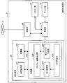
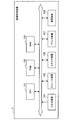
- FIG. 1 is a block diagram for explaining the configuration of an image forming apparatus 1 according to the first embodiment of the present invention.
- the image forming apparatus 1 according to the present embodiment is an information processing apparatus including a display device 10, a scanner unit 12, a printer unit 14, a control unit 16, and a communication unit 18.
- the image forming apparatus 1 according to the present embodiment has, for example, a copy function, and may have a scanner function, a facsimile function, an internet facsimile function, a network printer function, and the like.
- the configuration of the display device 10 provided in the image forming apparatus 1 according to the present embodiment will be described in detail.
- the display device 10 is an information processing apparatus having a display function of displaying various screens related to the function of the image forming apparatus 1 and an input function of receiving an input from a user.
- the display device 10 displays a setting screen for performing setting related to the operation of the image forming apparatus 1 such as double-sided printing setting, and specifies the setting based on an input from the user.
- the display device 10 provides the control unit 16 with the information of the specified setting.
- the display device 10 displays a preview screen according to the operation result of the image forming apparatus 1 such as the print result. The detailed configuration of the display device 10 will be described later.
- the scanner unit 12 reads image information from a document based on settings and control by the control unit 16.
- the printer unit 14 prints (outputs) the image information on, for example, a print sheet based on the setting and control by the control unit 16.
- image information to be printed as one surface (one page) by the printer unit 14 may be referred to as document data.
- data including one or a plurality of document data to be printed continuously or simultaneously by the printer unit 14 may be referred to as print data.
- An example in which print data includes a plurality of document data will be described below.
- the control unit 16 controls each component of the image forming apparatus 1. For example, the control unit 16 provides the display device 10 with information on the current setting status, and receives setting information from the display device 10 to reflect the setting. Further, the control unit 16 controls the scanner unit 12 and the printer unit 14 to realize various functions such as a copy function that the image forming apparatus 1 has.
- the control unit 16 according to the present embodiment reflects a setting related to double-sided printing specified by the display device 10 described later, and controls the scanner unit 12 and the printer unit 14 based on the setting. Further, the control unit 16 provides the display device 10 and the printer unit 14 with the print data obtained based on the scanner unit 12.
- control unit 16 may control the communication by the communication unit 18 and transmit / receive information to / from an information processing apparatus (not shown) connected to the communication network 5 shown in FIG. 1.
- the control unit 16 receives print data and setting information from the information processing apparatus connected to the communication network 5 via the communication unit 18, and causes the printer unit 14 to print based on the received print data and setting. It is also good.
- the control unit 16 may cause another information processing apparatus connected to the communication network 5 to transmit information on the current setting status via the communication unit 18. With such a configuration, for example, a network printer function in which the image forming apparatus 1 is operated by another information processing apparatus connected to the communication network 5 is realized.
- the communication unit 18 is a communication interface that mediates communication with another device.
- the communication unit 18 supports any wireless communication protocol or wired communication protocol, and establishes a communication connection with another device via, for example, the communication network 5 shown in FIG.
- the image forming apparatus 1 transmits the information of the current setting status etc. to the other information processing apparatus connected to the communication network 5, and the other information processing apparatus connected to the communication network 5 It is possible to receive information and print data.
- the communication network 5 is a wired or wireless transmission path of information transmitted from an apparatus or system connected to the communication network 5.
- the communication network 5 may include the Internet, a public network such as a telephone network, a satellite communication network, or various LANs (Local Area Networks) including Ethernet (registered trademark), WAN (Wide Area Network), etc. .
- the communication network 5 may also include a dedicated line network such as an IP-VPN (Internet Protocol-Virtual Private Network).
- the display device 10 is an information processing device including a display operation unit 110, a control unit 120, and a storage unit 130.
- the display operation unit 110 has a display function and an input function for receiving an input from the user.
- the display operation unit 110 may be realized by, for example, a touch panel display capable of detecting a touch operation.
- FIG. 1 shows an example in which the display device 10 includes the display operation unit 110 in which the display function and the input function are integrated, the display device 10 includes a display unit having the display function and an input unit having the input function. May be provided separately.
- the display operation unit 110 is controlled by the control unit 120 described later, and displays various screens for operating various functions of the image forming apparatus 1. Further, the display operation unit 110 provides the control unit 120 with information on the user's input on the displayed screen.
- the control unit 120 controls each component of the display device 10.
- the control unit 120 also functions as a situation specifying unit 122, a display control unit 124, a preview image generation unit 126, and a material data generation unit 128, as shown in FIG.
- the situation specifying unit 122 specifies a setting specifying function as a setting specifying unit that specifies a setting situation related to the image forming apparatus 1 and a behavior state related to the behavior of the display object that the display control unit 124 causes the display operation unit 110 to display. It has a behavior specifying function as a behavior specifying unit.
- the situation specifying unit 122 may receive information on the current setting situation from the control unit 16 of the image forming apparatus 1 to specify the setting situation, or the setting situation based on the user's input received by the display operation unit 110. May be identified.
- the status specifying unit 122 provides the control unit 16 of the image forming apparatus 1 with information of the setting to be changed.
- the setting status specified by the status specifying unit 122 in the present embodiment may include duplex setting related to printing of print data including a plurality of document data.
- the value of double-sided setting may be, for example, either “long side binding”, which is a value indicating double-sided printing, or “off”, which is a value indicating single-sided printing.
- the situation specifying unit 122 may specify the behavior situation based on the user's input received by the display operation unit 110. For example, the situation specifying unit 122 behaves according to the user's input to the display object displayed on the display operation unit 110. The situation may be identified. Also, the situation specifying unit 122 may specify the behavior situation so as to change according to time.
- the behavior status specified by the status specifying unit 122 in the present embodiment is, for example, reverse behavior indicating whether or not the display object is flipped to the left and right, and whether the display surface of the display object is front or back.
- the display surface behavior shown may be included.
- the value of the inversion behavior may be either “YES” indicating inversion or “NO” indicating non-inversion.
- the value of the display surface behavior may be either “front” indicating that the display surface is front or “back” indicating that the display surface is back.
- the display control unit 124 has a display control function of controlling the display operation unit 110 to display various screens related to the function of the image forming apparatus 1. For example, the display control unit 124 displays a setting screen for performing settings related to the operation of the image forming apparatus 1 such as duplex printing setting. The display control unit 124 also displays a preview screen related to the operation result of the image forming apparatus 1, such as the printing result by the image forming apparatus 1.
- the display control unit 124 combines the first surface, which is the front surface in printing, and the second surface, which is the back surface in printing, on the preview screen of the print result based on the print data and the duplex setting.
- the display object may be displayed on the display operation unit 110.
- the display object to be displayed by the display control unit 124 is a predetermined area of the first document data corresponding to the first side. And a predetermined area of the second original data corresponding to the second side.
- the second document data is, for example, document data of a page next to the first document data in the print data.
- the display object to be displayed by the display control unit 124 includes a predetermined region of the first document data corresponding to the first surface, and is included in the print data It is not necessary to include an area of original data other than one original data.
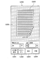
- FIG. 2 is an explanatory diagram for describing an example of a preview screen displayed by the display control unit 124 and a display object.
- the preview screen U100 includes a display object D100 that indicates the first print medium in the print result.
- the preview screen U100 may include a second display object D110 in the print result and buttons U101 to U104.
- buttons U101 to U103 are, for example, buttons for changing and confirming the setting status, and when the user operates the display operation unit 110 to press the buttons U101 to U103, the display control unit 124 displays a setting screen. May be For example, in the setting screen displayed after the user presses the button U101, it is possible to change the duplex setting relating to duplex printing.
- a button U104 is a button for starting printing, and when the user operates the display operation unit 110 and presses the button U104, a command signal for starting printing is sent from the control unit 120 to the image forming apparatus. 1 is output to the control unit 16.
- the display object D100 simulates one print medium having the first surface and the second surface in the print result, and regardless of the behavior status and the setting status, the first surface And at least a partial area of the second surface.
- the value of the inversion behavior is “NO”, the value of the display surface behavior is “front”, and the value of the both sides setting is “off”.
- the user can easily grasp that the current value of the both-side setting is “off”. Note that a specific example of the display object in other behavior states and setting states (double-sided setting) will be described later with reference to FIG.
- the display control unit 124 may display the display object by overlapping the preview image P100 and the sheet image Y100 as illustrated in FIG. 2.
- the preview image P100 is an image showing the print result itself which does not include the print sheet.
- the preview image P100 is, for example, an image obtained by combining the first side and the second side in the print result when printing the document data in the current setting situation, and is generated by the preview image generation unit 126 described later. It is also good.
- the sheet image Y100 is an image showing a printing sheet as shown in FIG. 2, and is an image including at least a partial area of one side of the printing sheet and at least a partial area of the other side. It is also good.
- the size of the preview image P100 may be a size corresponding to the paper image Y100, and may be, for example, the same size.
- the preview image P100 and the sheet image Y100 may be superimposed on the same coordinates.
- the display object D100 indicates in advance the print result when the document data is printed on the print sheet under the current setting condition. effective.
- the preview image as described above may be generated in advance by a preview image generation unit 126 described later, and stored in the storage unit 130. Then, the display control unit 124 may specify one preview image to be superimposed on the sheet image from the plurality of preview images stored in the storage unit 130 based on the duplex setting (setting status) and the behavior status. . With such a configuration, the display control unit 124 can rapidly display the display object corresponding to the change when the change in the behavior state or the setting state occurs.
- the display control unit 124 may specify one sheet image to be superimposed on the preview image from the plurality of sheet images stored in the storage unit 130 based on the behavior status.
- a specific example of specifying the preview image and the sheet image by the display control unit 124 will be described later with reference to FIG.
- the preview image generation unit 126 generates a preview image indicating the print result not including the print sheet as described with reference to FIG. 2 based on the material data generated by the material data generation unit 128 described later.
- the preview image generation unit 126 may generate a preview image by performing predetermined processing on, for example, one or a plurality of pieces of material data.
- the processing of the material data by the preview image generation unit 126 may include, for example, movement, rotation, scaling, and distortion of the material data.
- the preview image generation unit 126 generates a first material generated from the first document data included in the print data as a preview image when the duplex setting is long-side binding (an example of a value indicating duplex printing).
- the preview image may be generated by combining the data and the second material data generated from the second document data which is the document data of the next page of the first document data.
- the preview image generation unit 126 may generate a preview image based on the first document data as a preview image when the duplex setting is off (an example of a value indicating single-sided printing).
- the first document data is document data corresponding to the front surface (first surface) in printing
- the second document data is document data corresponding to the back surface (second surface) in printing.
- the preview image generated by the preview image generation unit 126 may be provided to the display control unit 124 or may be stored in the storage unit 130.
- the preview image generation unit 126 may generate preview images of all patterns based on the combination of the behavior status and the setting status in advance and store the preview image in the storage unit 130 before the preview screen is displayed.
- the material data generation unit 128 cuts out a predetermined area of the document data included in the print data, and generates material data which is data for generating a preview image.
- the material data generated by the material data generation unit 128 may be provided to the preview image generation unit 126 or may be stored in the storage unit 130.
- the material data generation unit 128 generates, in advance, material data of all patterns that can be used to generate a preview image based on a combination of the behavior status and the setting status. It may be stored. Note that an example of an area cut out by the material data generation unit 128 and a specific example of material data generated by the material data generation unit 128 will be described later.
- the print data including the document data used to generate the material data by the material data generation unit 128 may be provided from, for example, the control unit 16 of the image forming apparatus 1 or may be stored in advance in the storage unit 130. Good.
- the storage unit 130 stores programs and parameters for each component of the display device 10 to function.
- the storage unit 130 may store a sheet image, print data, and the like.
- the storage unit 130 stores information specified or generated by each configuration of the control unit 120.
- the storage unit 130 may store a plurality of material data provided from the control unit 120 and a plurality of preview images.
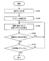
- FIG. 3 is an explanatory view showing an operation example according to the present embodiment.
- the material data generation unit 128 cuts out a predetermined area of document data included in the print data to generate material data (S102).
- material data generation unit 128 cuts out a predetermined area of document data included in the print data to generate material data (S102).
- material data generation unit 128 specific examples of material data generation by the material data generation unit 128 according to the present embodiment will be described with reference to FIGS. 4 to 10.
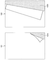
- FIG. 4 is an explanatory view showing an example of a sheet image according to the present embodiment.
- the normal image Y12 shown in FIG. 4 is a paper image used when the reverse behavior is "NO”
- the reverse image Y14 is a paper image used when the reverse behavior is "YES”.
- FIG. 5 is an explanatory diagram for explaining each area in the sheet image shown in FIG.
- the normal image Y12 includes a front surface display area Y122 and a back surface display area Y124
- the reverse image Y14 includes a front surface display area Y142 and a back surface display area Y144.
- the front surface display area is, for example, an area of the display surface which occupies more area when each sheet image is displayed on the display operation unit 110 as a part of the display object.
- the back surface display area is an area displayed as a surface on the back side of the display surface, that is, a surface in which the display surface is turned over (folded).
- the front surface display region may be called a visual front surface display region
- the rear surface display region may be called a visual rear surface display region.
- the material data generation unit 128 may cut out the corresponding document data area in the visual front surface display area and the back surface display area of the display object to generate the material data.
- FIG. 6 is an explanatory view showing an area of document data cut out by the material data generation unit 128. As shown in FIG.
- an area surrounded by a broken line is an area to be cut out by the material data generation unit 128.
- the surface display area C1 of the document data C11 shown in FIG. 6 is an area corresponding to the surface display area Y122 of the normal image Y12 shown in FIG.
- the back surface display area C2 of the document data C12 shown in FIG. 6 is an area corresponding to the back surface display area Y124 of the normal image Y12 shown in FIG.
- the front display area C3 of the document data C13 shown in FIG. 6 is an area corresponding to the front display area Y142 of the reverse image Y14 shown in FIG.
- the back surface display area C4 of the document data C14 shown in FIG. 6 is an area corresponding to the back surface display area Y144 of the reverse image Y14 shown in FIG.
- FIG. 7 is an explanatory view showing an example of document data included in print data according to the present operation example.
- the print data according to this operation example includes the first page document data G1 (first document data) and the second page document data G2 (second document data) shown in FIG.
- the material data generation unit 128 according to the present embodiment cuts out the regions C1 to C4 described with reference to FIG. 6 from the document data G1 according to the table shown in FIG. 8 to generate the material data M11 to M14 shown in FIG. Do.
- the material data generation unit 128 according to the present embodiment cuts out the regions C1 to C4 described with reference to FIG. 6 from the document data G2 according to the table shown in FIG. Generate M24.
- step S104 the preview image generation unit 126 generates a preview image based on the material data generated in step S102.
- the preview image generation unit 126 generates a preview image based on the material data generated in step S102.
- FIGS. 9 and 10 are explanatory diagrams for explaining preview image generation processing by the preview image generation unit 126 according to the present embodiment.
- the preview image generation unit 126 generates a preview image from the material data shown in FIGS. 9 and 10 based on the behavior status (display surface behavior and reverse behavior) and the setting status (both sides setting). Specify the material data for generation used to generate.
- the preview image generation unit 126 processes the specified material data for generation so as to match the corresponding regions, and generates the preview images P1 to P8 shown in FIG. As shown in FIGS. 11 and 12, preview images P3, P4, P7, and P8 in the case where the duplex setting is a value (long side binding) indicating duplex are used as material data based on document data G1 and document data G2. It is the image in which the material data based on it was synthesize
- the preview image generation unit 126 may store the generated preview images P1 to P8 in the storage unit 130 in step S104.
- step S106 the display control unit 124 causes the display object to be displayed by overlapping the preview image and the sheet image according to the behavior status and the setting status.
- the display control unit 124 causes the display object to be displayed by overlapping the preview image and the sheet image according to the behavior status and the setting status.
- FIG. 13 and 14 are explanatory diagrams for describing a specific example of the display object to be displayed by the display control unit 124 according to the present embodiment.
- the display control unit 124 displays the preview image shown in FIG. 12 and FIG. 4 based on the behavior status (display surface behavior and reverse behavior) and the setting status (double-sided setting) as shown in the table of FIG. From the paper image, the combination of the preview image and the paper image to be superimposed is specified.
- the display control unit 124 causes the display operation unit 110 to display the display objects D1 to D8 shown in FIG. 14 by overlapping the specified preview image and the sheet image.
- step S108 If a change occurs in the behavior state or the setting state based on the user's input via the display operation unit 110 (YES in S108), the process returns to step S106, and the display control unit 124 changes the behavior state and the setting state Display the display object according to.
- FIG. 15 is an explanatory view showing a display transition example of a display object according to the behavior status and the setting status.
- the display object D1 is displayed when the behavior status and the setting status are in the initial state “display surface behavior: surface, reverse behavior: NO, both sides setting: off”. Subsequently, when the behavior status and the setting status change to “display surface behavior: front surface, reverse behavior: NO, both surface configuration: long side binding”, the display object to be displayed transitions to the display object D3. Furthermore, when the behavior status and the setting status change to the reverse status “display surface behavior: back surface, reverse behavior: YES, both sides setting: long side binding”, the display object to be displayed transitions to the display object D4. Furthermore, when the behavior status and the setting status change to the back surface status “display surface behavior: back surface, reverse behavior: NO, both sides setting: long side binding”, the display object to be displayed transitions to the display object D7.
- steps S106 to S108 are repeated until printing is started or canceled based on the user's input via display operation unit 110, and when printing is started or canceled (YES in S110), the process ends. Do.
- the first embodiment of the present invention has been described above.
- the user can easily grasp the current duplex setting.
- the user can grasp the state of both the front side and the back side in printing only by confirming one display object displayed on the preview screen.
- Second embodiment In the first embodiment described above, an example has been described in which material data corresponding to a visual front surface display area and material data corresponding to a visual rear surface display area are generated. On the other hand, in the following, as a second embodiment, an example in which material data corresponding to a visual surface display area is not generated will be described.
- the image forming apparatus according to the second embodiment of the present invention is, for example, an information processing apparatus having a copy function, as in the image forming apparatus according to the first embodiment.
- the image forming apparatus according to the second embodiment may have, for example, a scanner function, a facsimile function, an internet facsimile function, and a network printer function.
- the image forming apparatus according to the second embodiment of the present invention has a configuration similar to that of the image forming apparatus 1 according to the first embodiment described with reference to FIG. While explaining.
- the configuration of the image forming apparatus according to the second embodiment will be described below with reference to FIG.
- FIG. 16 is an explanatory view showing a configuration example of the image forming apparatus according to the present embodiment.
- the image forming apparatus 2 according to the present embodiment includes, for example, a display device 20, a scanner unit 12, a printer unit 14, a control unit 16, and a communication unit 18.
- the configurations shown in FIG. 16 the configurations substantially the same as the configurations shown in FIG.
- the display device 20 shown in FIG. 16 is different from the display device 10 in that the function of the control unit 220 is partially different from the function of the control unit 120 of the display device 10 shown in FIG.
- the control unit 220 controls each component of the display device 20 as the control unit 120 does.
- the control unit 220 also functions as a situation specifying unit 122, a display control unit 224, a preview image generation unit 226, and a material data generation unit 228 as shown in FIG.
- the function of the situation specifying unit 122 is the same as the situation specifying unit 122 described with reference to FIG.
- the display control unit 224 controls the display operation unit 110 to display various screens related to the function of the image forming apparatus 2.
- the display control unit 224 according to the present embodiment is a display control unit 124 in that the display object is displayed by overlapping the paper image and the preview image in each of the visual front surface display area and the visual rear surface display area. It is different from
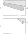
- FIG. 17 is an explanatory view showing an example of a sheet image and a preview image according to the present embodiment.
- a normal image Y202 shown in FIG. 17 is an example of a sheet image superimposed in the front surface display area.
- a preview image P202 shown in FIG. 17 is an example of a preview image superimposed in the front surface display area.
- the preview image P 202 superimposed in the front surface display area may be document data itself corresponding to the front surface display area.
- a reverse image Y 204 shown in FIG. 17 is an example of a sheet image to be superimposed in the back surface display area.
- a preview image P204 shown in FIG. 17 is an example of a preview image superimposed in the back surface display area.
- FIG. 18 is an explanatory diagram for describing an example of a preview screen displayed by the display control unit 224 and a display object.
- the preview screen U200 includes a display object D200 indicating a print medium in the print result.
- the preview screen U200 may include buttons U201 to U204.
- the functions of the buttons U201 to U204 shown in FIG. 18 are the same as the functions of the buttons U101 to U104 shown in FIG.
- the display control unit 224 displays, for example, the display object D200 illustrated in FIG. 18 by superimposing the normal image Y202, the preview image P202, the reverse image Y204, and the preview image P204 illustrated in FIG. 17 in the above-described order.
- the functions and effects of the displayed display object D200 are the same as those of the display object D100 described with reference to FIG.
- the display control unit 224 may specify the preview image and the paper image to be superimposed for each of the visual front surface display area and the visual rear surface display area.
- the display control unit 224 selects one preview image (original data) overlapped in the visual back surface display area from a plurality of original data included in the print data based on the duplex setting (setting status) and the behavior status. May be identified.
- the display control unit 224 selects one preview image that is superimposed on the sheet image in the visual reverse surface display area from the plurality of preview images stored in the storage unit 130 based on the duplex setting (setting status) and the behavior status. An image may be identified.
- the sheet image superimposed in the visual front surface display area may be only the normal image Y 202 shown in FIG. 17, and the normal image Y 202 may be simply referred to as a normal image hereinafter.
- the display control unit 224 may specify one sheet image to be overlapped in the visual back surface display area from the plurality of sheet images stored in the storage unit 130 based on the behavior status. A specific example of specifying the preview image and the sheet image by the display control unit 224 will be described later with reference to FIG.
- the preview image generation unit 226 generates a preview image in the same manner as the preview image generation unit 126 described with reference to FIG.
- the preview image generation unit 226 according to the present embodiment may generate a preview image corresponding to the back surface display region based on the material data corresponding to the back surface display region generated by the material data generation unit 228 described later.
- the material data generation unit 228 cuts out a predetermined area of document data included in print data to generate material data.
- the material data generation unit 228 may generate only material data corresponding to the back surface display area. Note that an example of an area cut out by the material data generation unit 228 and a specific example of the material data generated by the material data generation unit 228 will be described later.
- the material data generation unit 228 cuts out a predetermined area of document data included in print data to generate material data (S102).
- material data generation unit 228 cuts out a predetermined area of document data included in print data to generate material data (S102).
- material data generation unit 228 cuts out a predetermined area of document data included in print data to generate material data (S102).
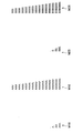
- FIG. 19 is an explanatory view showing an example of a sheet image corresponding to the back surface display area according to the present embodiment.
- the reverse image Y21 shown in FIG. 19 is a sheet image used in the back surface display area when the reverse behavior is “NO”, and the reverse image Y22 is used in the back surface display area when the reverse behavior is “YES”. Paper image.
- the colors of the background area Y212 and the background area Y222 may be the same as the color of the background area U205 of the preview screen U200 shown in FIG. According to such a configuration, the boundary between the display object in which the reverse image Y21 and the reverse image Y22 are displayed in an overlapping manner and the background area U205 is aligned, and the user does not feel uncomfortable.
- FIG. 20 is an explanatory diagram for explaining each area in the sheet image shown in FIG.
- the reverse image Y21 includes a back surface display area Y214
- the reverse image Y22 includes a back surface display area Y224.
- the material data generation unit 228 according to the present embodiment generates the material data by cutting out the area of the document data corresponding to the visual back surface display area in the display object.
- FIG. 21 is an explanatory view showing a region of document data cut out by the material data generation unit 228. As shown in FIG.
- the area surrounded by the broken line is the area to be cut out by the material data generation unit 228.
- the back surface display area C5 of the document data C25 shown in FIG. 21 is an area corresponding to the back surface display area Y214 of the reverse image Y21 shown in FIG.
- the back surface display area C6 of the document data C26 shown in FIG. 21 is an area corresponding to the back surface display area Y224 of the reverse image Y22 shown in FIG.
- FIG. 22 and FIG. 23 are explanatory diagrams for explaining the generation process of the material data by the material data generation unit 228 according to the present embodiment.
- the material data generation unit 228 according to the present embodiment cuts out the regions C5 and C6 described with reference to FIG. 21 from the document data G1 according to the table shown in FIG. 22, and generates material data M15 and M16 shown in FIG. Do.
- the material data generation unit 228 according to the present embodiment cuts out the regions C5 and C6 described with reference to FIG. 21 from the document data G2 according to the table shown in FIG. Generate M26.
- the material data generated by the material data generation unit 228 according to the present embodiment is only material data corresponding to the back surface display area, and has been described with reference to FIGS. It is less than the material data generated in the first embodiment.
- step S104 the preview image generation unit 226 generates a preview image based on the material data generated in step S102.
- the preview image generation unit 226 generates a preview image based on the material data generated in step S102.
- FIGS. 24 and 25 are explanatory diagrams for explaining preview image generation processing by the preview image generation unit 226 according to the present embodiment.
- the preview image generation unit 226 generates a preview image from the material data shown in FIG. 23 based on the behavior status (display surface behavior and reverse behavior) and the setting status (double-sided setting) as shown in the table of FIG. Identify the material data for generation used in
- preview image generation unit 226 processes the specified material data for generation so as to match the back surface display area of the paper image corresponding to each material data, and generates preview images P21 to P24 shown in FIG. 25. Do. As shown in FIGS. 24 and 25, the preview image generated by the preview image generation unit 226 according to the present embodiment is generated only from material data corresponding to the back surface display area, as shown in FIGS. 11 and 12. There are fewer than the preview images generated in the first embodiment described.
- the preview image generation unit 226 may store the generated preview images P21 to P24 in the storage unit 130 in step S104.
- step S106 the display control unit 224 causes the display object to be displayed by overlapping the preview image and the sheet image according to the behavior status and the setting status.
- the display control unit 224 causes the display object to be displayed by overlapping the preview image and the sheet image according to the behavior status and the setting status.
- FIG. 26 and FIG. 27 are explanatory diagrams for describing specific examples of display objects to be displayed by the display control unit 224 according to the present embodiment.
- the display control unit 224 displays a preview superimposed on each of the front display area and the back display area based on the behavior status (display surface behavior and reverse behavior) and the setting status (double-sided setting). Identify combinations of images and paper images.
- the preview image to be superimposed in the front display area is specified from the original data G1, G2 included in the print data.
- the sheet image to be superimposed in the front surface display area is a normal image (normal image Y202 shown in FIG. 17).
- preview images to be superimposed in the back surface display area are specified from preview images P21 to P24 shown in FIG. 25, and the sheet images to be superimposed in the back surface display area are specified from inverted image Y21 and inverted image Y22 shown in FIG. Be done.
- the display control unit 224 causes the display operation unit 110 to display the display objects D21 to D28 shown in FIG. 27 by overlapping the specified preview image and the sheet image.
- step S108 If a change occurs in the behavior state or the setting state based on the user's input via the display operation unit 110 (YES in S108), the process returns to step S106, and the display control unit 224 changes the behavior state and the setting state Display the display object according to.
- FIG. 28 is an explanatory view showing a display transition example of the display object according to the behavior status and the setting status.
- the display object D21 is displayed when the behavior state and the setting state are in the initial state “display surface behavior: surface, reverse behavior: NO, both sides setting: off”. Subsequently, when the behavior status and the setting status change to “display surface behavior: front surface, reverse behavior: NO, both surface configuration: long side binding”, the displayed display object transitions to the display object D23. Further, when the behavior status and the setting status change to “display surface behavior: back surface, reverse behavior: YES, both sides setting: long side binding”, the display object to be displayed transitions to the display object D24. Furthermore, when the behavior status and the setting status change to the back surface status “display surface behavior: back surface, reverse behavior: NO, both sides setting: long side binding”, the display object to be displayed transitions to the display object D 27.
- steps S106 to S108 are repeated until printing is started or canceled based on the user's input via display operation unit 110, and when printing is started or canceled (YES in S110), the process ends. Do.
- the processing amounts in steps S102 and S104 of FIG. 3 are stored. Reduce the amount of data
- the preview image used to display the display object is different between the front surface display area and the back surface display area, only the preview image corresponding to the front surface display area is enlarged or A function of reducing the size can also be realized.
- the display control unit is a display object including dummy data instead of the predetermined area of the document data. May be displayed.
- the material data generation unit cuts out a predetermined area from document data to generate material data, it determines whether or not the predetermined area is blank, and if it is blank, it is determined from dummy document data.
- a predetermined area may be cut out to generate material data.
- the dummy document data may be, for example, document data entirely filled with characters, pictures, predetermined colors, and the like.
- the display control unit can display a display object including, as dummy data, a preview image including material data generated from dummy document data.
- a dummy paper image or a dummy preview image may be generated in advance and stored in the storage unit.
- the display control unit displays the display object by overlapping the dummy paper image or the dummy preview image when the predetermined area of the document data corresponding to the side to be printed based on the duplex setting is blank. May be displayed.
- the display control unit displays the display object including the enlarged predetermined area obtained by enlarging the predetermined area.
- the control unit of the display device enlarges the area of the corresponding document data by making the reversed (flipped) portion of the paper image larger (larger reverse) than the paper image based on the current behavior situation.
- the enlarged predetermined area may be identified. Further, the enlargement predetermined area may be enlarged until the enlargement predetermined area in the document data is not blank.
- the determination as to whether or not the predetermined area in the document data is blank is performed, for example, by determining that the blank area in the document data is blank when the blank ratio of the predetermined area is equal to or more than a predetermined value. It is also good.
- the display control unit may have the functions of a material data generation unit and a preview image generation unit, dynamically generate a preview image according to the behavior status and the setting status, and may display a display object.
- the display device may further include a display object generation unit that generates a display object by combining the paper image and the preview image.
- the display object generation unit may store the generated display object in the storage unit in advance, and the display control unit may specify the display object to be displayed from the storage unit according to the behavior status and the setting status.
- the display control unit can display the display object corresponding to the change at higher speed when the change in the behavior state or the setting state occurs.
- the display transition of the display object due to the change of the behavior state becomes a smoother transition.
- FIG. 29 is an explanatory view showing an example of the hardware configuration of the image forming apparatus 1.
- the image forming apparatus 1 includes a central processing unit (CPU) 151, a read only memory (ROM) 152, a random access memory (RAM) 153, an input / output device 154, and a storage device 155. , A scanner device 156, a printer device 157, and a communication device 158.
- the CPU 151 functions as an arithmetic processing unit and a control unit, and controls the overall operation in the image forming apparatus 1 according to various programs. Also, the CPU 151 may be a microprocessor.
- the ROM 152 stores programs used by the CPU 151, calculation parameters, and the like.
- the RAM 153 temporarily stores programs used in the execution of the CPU 151, parameters that change appropriately in the execution, and the like. These are mutually connected by a host bus configured of a CPU bus and the like.
- the functions of the control unit 120 and the control unit 16 are realized mainly by the cooperation of the CPU 151, the ROM 152, and the RAM 153 with the software.
- the input / output device 154 includes an input unit such as a touch panel for the user to input information, and a display unit for displaying a captured image, a generated image, and the like.
- the input means includes an input control circuit that generates an input signal based on an input by the user and outputs the generated input signal to the CPU 151.
- the input means may include a mouse, a keyboard, a touch panel, a button, a microphone, a switch, a lever, and the like.
- the user of the image forming apparatus 1 can input various data to the image forming apparatus 1 and instruct processing operations by operating the input / output device 154.
- the output means includes an audio output device such as a speaker and a headphone, and the audio output device converts audio data and the like into audio and outputs the audio.
- the input / output device 154 corresponds to the display / operation unit 110 described with reference to FIG.
- the storage device 155 is a device for storing data.
- the storage device 155 may include a storage medium, a recording device that records data in the storage medium, a reading device that reads data from the storage medium, and a deletion device that deletes data recorded in the storage medium.
- the storage device 155 stores programs executed by the CPU 151 and various data.
- the scanner device 156 includes an ADF (Auto Document Feeder) and a document table, and reads image information from a document sheet.
- the scanner device 156 corresponds to the scanner unit 12 described with reference to FIG.
- the printer device 157 prints on a sheet according to image data.
- the printer device 157 corresponds to the printer unit 14 described with reference to FIG.
- the communication device 158 is, for example, a communication interface configured of a communication device or the like for connecting to a transmission line such as the communication network 5 described with reference to FIG.
- the communication device 158 may also include a wireless local area network (LAN) compatible communication device, a long term evolution (LTE) compatible communication device, a wire communication device performing wired communication, or a Bluetooth (registered trademark) communication device.
- LAN wireless local area network
- LTE long term evolution
- wire communication device performing wired communication
- Bluetooth registered trademark
- the image forming apparatus 2 also has hardware equivalent to the CPU 151, the ROM 152, the RAM 153, and the like, similarly to the image forming apparatus 1. Then, the cooperation of the hardware and software of the image forming apparatus 2 realizes, for example, the function and the like of the control unit 220.
- the present invention is not limited to such an example.
- Other devices may have the functions of the display device 10 and the display device 20 described above.
- an information processing device (not shown) connected to the communication network 5 described with reference to FIG.
- the display device 10 or the condition specifying unit of the display device 20 may have the functions of a display control unit, a preview image generation unit, and a material data generation unit.
- the information processing apparatus (not shown) connected to the communication network 5 may be an information processing apparatus such as a PC (Personal Computer), a tablet PC, or a smartphone.
- Reference Signs List 1 image forming apparatus 5 communication network 10 display unit 12 scanner unit 14 printer unit 16 control unit 18 communication unit 110 display operation unit 120 control unit 122 condition specification unit 124 display control unit 126 preview image generation unit 128 material data generation unit 130 storage unit
Landscapes
- Engineering & Computer Science (AREA)
- Multimedia (AREA)
- Signal Processing (AREA)
- General Engineering & Computer Science (AREA)
- Theoretical Computer Science (AREA)
- General Physics & Mathematics (AREA)
- Physics & Mathematics (AREA)
- Human Computer Interaction (AREA)
- Accessory Devices And Overall Control Thereof (AREA)
- Record Information Processing For Printing (AREA)
- Editing Of Facsimile Originals (AREA)
- User Interface Of Digital Computer (AREA)
- Facsimiles In General (AREA)
- Control Or Security For Electrophotography (AREA)
Abstract
【課題】情報処理装置、及び記録媒体を提供する。 【解決手段】複数の原稿データを含む印刷データの印刷に係る両面設定を特定する設定特定部と、前記印刷データと前記両面設定に基づいて、印刷における表面である第一の面、及び印刷における裏面である第二の面が合成された表示オブジェクトを表示させる表示制御部と、を備える情報処理装置。
Description
本発明は、情報処理装置、及び記録媒体に関する。
従来、1枚の印刷媒体の両面に印刷させるか、片面に印刷させるかについての両面設定が行われている。例えば、特許文献1には、デジタル複合機に搭載されたタッチパネルにおいて、所定操作により両面設定を含む印刷設定を行うことが可能な技術が開示されている。
また、印刷を行うためのアプリケーションにおいて、原稿データに基づいて印刷結果のプレビュー画面を印刷の実行前に表示させることも行われている。ユーザはプレビュー画面を見ることで、予め印刷結果を確認し、必要に応じて修正や設定変更等を行うことが可能である。
しかし、上記のような従来のプレビュー画面では、2つのオブジェクトを表示させることで表面と裏面を別々にプレビュー表示させる、または原稿データを切り替えることで、印刷における表面と裏面をプレビュー表示させる処理が行われていた。そのため、印刷結果のプレビュー画面において、ユーザが現在の両面設定を直感的に把握することが困難であるという問題があった。
そこで、本発明は、上記問題に鑑みてなされたものであり、本発明の目的とするところは、ユーザが現在の両面設定をより容易に把握することが可能な、新規かつ改良された情報処理装置を提供することにある。
上記課題を解決するために、本発明のある観点によれば、複数の原稿データを含む印刷データの印刷に係る両面設定を特定する設定特定部と、前記印刷データと前記両面設定に基づいて、印刷における表面である第一の面、及び印刷における裏面である第二の面が合成された表示オブジェクトを表示させる表示制御部と、を備える情報処理装置が提供される。
前記両面設定が両面印刷を示す値である場合に前記表示制御部が表示させる前記表示オブジェクトは、前記第一の面に対応する原稿データの所定領域、及び前記第二の面に対応する原稿データの所定領域を含んでもよい。
前記表示制御部は、印刷結果を示すプレビュー画像と、印刷用紙を示す用紙画像を重ねることで、前記表示オブジェクトを表示させてもよい。
前記表示制御部は、前記両面設定に基づいて、複数のプレビュー画像から、前記用紙画像と重ねられるプレビュー画像を特定してもよい。
前記表示制御部は、前記表示オブジェクトの振舞に係る振舞状況にさらに基づいて、前記複数のプレビュー画像から、前記用紙画像と重ねられるプレビュー画像を特定してもよい。
前記印刷データに含まれる前記原稿データから前記所定領域を切り抜いて生成される素材データに基づいて、前記プレビュー画像を生成するプレビュー画像生成部をさらに備えてもよい。
前記プレビュー画像生成部は、前記第一の面に対応する原稿データから生成される前記素材データと、前記第二の面に対応する原稿データから生成される前記素材データと、を合成して、前記プレビュー画像を生成してもよい。
前記表示制御部は、視覚上の表面表示領域、及び視覚上の裏面表示領域のそれぞれにおいて、前記用紙画像と前記プレビュー画像を重ねることで、前記表示オブジェクトを表示させてもよい。
前記表示制御部は、前記両面設定に基づいて、複数のプレビュー画像から、前記視覚上の裏面表示領域において前記用紙画像と重ねられるプレビュー画像を特定してもよい。
前記表示制御部は、前記表示オブジェクトの振舞に係る振舞状況にさらに基づいて、前記複数のプレビュー画像から、前記視覚上の裏面表示領域において前記用紙画像と重ねられるプレビュー画像を特定してもよい。
前記複数のプレビュー画像を記憶する、記憶部をさらに備えてもよい。
前記両面設定が片面印刷を示す値である場合に前記表示制御部が表示させる前記表示オブジェクトは、前記第一の面に対応する原稿データの少なくとも一部の領域を含み、前記第一の面に対応する原稿データ以外の、前記印刷データに含まれる原稿データの領域を含まなくてもよい。
前記表示制御部は、前記両面設定に基づいて印刷されるべき面に対応する原稿データの前記所定領域が空白である場合に、ダミーのデータを含む表示オブジェクトを表示させてもよい。
前記表示制御部は、前記両面設定に基づいて印刷されるべき面に対応する原稿データの前記所定領域が空白である場合に、前記所定領域を拡大した拡大所定領域を含む表示オブジェクトを表示させてもよい。
また、上記課題を解決するために、本発明の別の観点によれば、コンピュータに、複数の原稿データを含む印刷データの印刷に係る両面設定を特定する設定特定機能と、前記印刷データと前記両面設定に基づいて、印刷における表面である第一の面、及び印刷における裏面である第二の面が合成された表示オブジェクトを表示させる表示制御機能と、を実現させるための、プログラムを記録したコンピュータ読み取り可能な記録媒体が提供される。
以上説明したように本発明によれば、ユーザが現在の両面設定をより容易に把握することが可能である。
本発明は、例えば表裏面を備えた一枚の紙に相当する、第一の面と第二の面を備えた一つの印刷媒体を模した表示オブジェクトを印刷結果のプレビュー画面において表示させることで、ユーザにとって現在の両面設定がより容易に把握可能となる。印刷機能やコピー機能のプレビュー表示において本発明が適用される場合、表示オブジェクトは、例えば文字や写真等からなる画像が印刷用紙に印刷されて出力される印刷結果をシミュレートしたものとなる。また、例えば第一の面は印刷における表面であり、第二の面は印刷における裏面であってもよい。
以下に添付図面を参照しながら、本発明の好適な実施の形態について詳細に説明する。なお、本明細書及び図面において、実質的に同一の機能構成を有する構成要素については、同一の符号を付することにより重複説明を省略する。
また、本明細書及び図面において、実質的に同一の機能構成を有する複数の構成要素を、同一の符号の後に異なるアルファベットを付して区別する場合もある。ただし、実質的に同一の機能構成を有する複数の構成要素の各々を特に区別する必要がない場合、同一符号のみを付する。
<<1.第一の実施形態>>
<1-1.第一の実施形態の構成例>
まず、図1を参照して、本発明の第一の実施形態にかかる画像形成装置の構成を説明する。
<1-1.第一の実施形態の構成例>
まず、図1を参照して、本発明の第一の実施形態にかかる画像形成装置の構成を説明する。
図1は、本発明の第一の実施形態に係る画像形成装置1の構成を説明するためのブロック図である。図1に示すように、本実施形態による画像形成装置1は、表示装置10、スキャナ部12、プリンタ部14、制御部16、通信部18を備える情報処理装置である。本実施形態による画像形成装置1は、例えばコピー機能を有し、また、スキャナ機能、ファクシミリ機能、インターネットファクシミリ機能、及びネットワークプリンタ機能などを有してもよい。以下、本実施形態の全体構成を説明した後、本実施形態に係る画像形成装置1が備える表示装置10の構成について、詳細に説明する。
表示装置10は、画像形成装置1の機能に係る各種画面を表示する表示機能、及びユーザからの入力を受け付ける入力機能を有する情報処理装置である。例えば、表示装置10は、例えば両面印刷設定等の、画像形成装置1の動作に係る設定を行うための設定画面を表示し、利用者からの入力に基づいて設定を特定する。また、表示装置10は、特定された設定の情報を制御部16に提供する。さらに、表示装置10は、印刷結果等の、画像形成装置1の動作結果に係るプレビュー画面を表示する。なお、表示装置10の詳細な構成については後述する。
スキャナ部12は、制御部16による設定、及び制御に基づいて、原稿から画像情報を読み取る。プリンタ部14は、制御部16による設定、及び制御に基づいて、画像情報を例えば印刷用紙に印刷(出力)する。以降では、プリンタ部14により1つの面(1頁)として印刷されるための画像情報を、原稿データと呼ぶ場合がある。また、プリンタ部14により連続的に、または同時に印刷される、1または複数の原稿データを含むデータを印刷データと呼ぶ場合がある。以下では、印刷データには複数の原稿データが含まれる例を説明する。
制御部16は、画像形成装置1の各構成を制御する。例えば、制御部16は、表示装置10に現在の設定状況の情報を提供し、また表示装置10から設定の情報を受け取って当該設定を反映させる。また、制御部16は、スキャナ部12、プリンタ部14を制御し、画像形成装置1が有するコピー機能等の各種機能を実現する。本実施形態に係る制御部16は、後述する表示装置10が特定した両面印刷に係る設定を反映させ、当該設定に基づいてスキャナ部12、プリンタ部14を制御する。また、制御部16は、スキャナ部12に基づいて得られる印刷データを表示装置10、及びプリンタ部14に提供する。
また、制御部16は、通信部18による通信を制御し、図1に示す通信網5に接続された不図示の情報処理装置と情報の送受信を行ってもよい。例えば制御部16は、通信部18を介して、通信網5に接続された情報処理装置から、印刷データと設定の情報を受け取り、受け取った印刷データと設定に基づいてプリンタ部14に印刷させてもよい。また、制御部16は、通信部18を介して、通信網5に接続された他の情報処理装置に現在の設定状況の情報を送信させてもよい。係る構成により、例えば、通信網5に接続された他の情報処理装置により画像形成装置1が操作されるネットワークプリンタ機能が実現される。
通信部18は、他の装置との間の通信を仲介する通信インタフェースである。通信部18は、任意の無線通信プロトコルまたは有線通信プロトコルをサポートし、例えば図1に示した通信網5を介して他の装置との間の通信接続を確立する。それにより、例えば、画像形成装置1が通信網5に接続された他の情報処理装置に現在の設定状況の情報等を送信し、及び通信網5に接続された他の情報処理装置から設定の情報と印刷データを受信することが可能となる。
なお、通信網5は、通信網5に接続されている装置、またはシステムから送信される情報の有線、または無線の伝送路である。例えば、通信網5は、インターネット、電話回線網、衛星通信網等の公衆回線網や、Ethernet(登録商標)を含む各種のLAN(Local Area Network)、WAN(Wide Area Network)等を含んでもよい。また、通信網5は、IP-VPN(Internet Protocol-Virtual Private Network)等の専用回線網を含んでもよい。
以上、本実施形態にかかる画像形成装置1の構成を説明した。続いて、本実施形態に係る画像形成装置1が有する表示装置10の構成について説明する。図1に示すように、表示装置10は、表示操作部110、制御部120、及び記憶部130を備える情報処理装置である。
表示操作部110は、表示機能と、ユーザの入力を受け付ける入力機能を有する。表示操作部110は、例えばタッチ操作を検出可能なタッチパネルディスプレイ等により実現されてもよい。なお、図1では表示装置10が表示機能と入力機能が一体化された表示操作部110を備える例を示したが、表示装置10は、表示機能を有する表示部と、入力機能を有する入力部を別々に備えてもよい。
また、表示操作部110は、後述する制御部120に制御されて、画像形成装置1の各種機能を操作するための各種画面を表示する。また、表示操作部110は、表示した画面に対するユーザの入力の情報を制御部120に提供する。
制御部120は、表示装置10の各構成を制御する。また、制御部120は、図1に示すように、状況特定部122、表示制御部124、プレビュー画像生成部126、素材データ生成部128としても機能する。
状況特定部122は、画像形成装置1に係る設定状況を特定する設定特定部としての設定特定機能と、表示制御部124が表示操作部110に表示させる表示オブジェクトの振舞に係る振舞状況を特定する振舞特定部としての振舞特定機能とを有する。
状況特定部122は、画像形成装置1の制御部16から現在の設定状況の情報を受け取って設定状況を特定してもよいし、表示操作部110が受け付けたユーザの入力に基づいて、設定状況を特定してもよい。表示操作部110が受け付けたユーザの入力に基づいて、設定状況が変更される場合、状況特定部122は、変更すべき設定の情報を画像形成装置1の制御部16に提供する。例えば、本実施形態において状況特定部122により特定される設定状況は、複数の原稿データを含む印刷データの印刷に係る両面設定を含んでもよい。また、本実施形態において、両面設定の値は、例えば両面印刷を示す値である「長辺とじ」、または片面印刷を示す値である「オフ」のいずれかであってもよい。
また、状況特定部122は、表示操作部110が受け付けたユーザの入力に基づいて、振舞状況を特定してもよく、例えば表示操作部110に表示された表示オブジェクトに対するユーザの入力に応じて振舞状況を特定してもよい。また、状況特定部122は、時間に応じて変化するように振舞状況を特定してもよい。
本実施形態において状況特定部122により特定される振舞状況は、例えば表示オブジェクトが左右に反転遷移しているか否かを示す反転振舞と、表示オブジェクトの表示面が表であるか裏であるかを示す表示面振舞を含んでもよい。本実施形態において反転振舞の値は、反転していることを示す「YES」、または反転していないことを示す「NO」のいずれかであってもよい。また、本実施形態において表示面振舞の値は、表示面が表であることを示す「表面」、または表示面が裏であることを示す「裏面」のいずれかであってもよい。なお、各振舞状況での表示オブジェクトの具体例については図13~15を参照して後述する。
表示制御部124は、表示操作部110を制御して、画像形成装置1の機能に係る各種画面を表示させる表示制御機能を有する。例えば、表示制御部124は、両面印刷設定等の、画像形成装置1の動作に係る設定を行うための設定画面を表示させる。また表示制御部124は、画像形成装置1による印刷結果等の、画像形成装置1の動作結果に係るプレビュー画面を表示させる。
本実施形態に係る表示制御部124は、印刷結果のプレビュー画面において、印刷データと両面設定に基づいて、印刷における表面である第一の面、及び印刷における裏面である第二の面が合成された表示オブジェクトを表示操作部110に表示させてもよい。
例えば、両面設定が両面印刷を示す値(例えば「長辺とじ」)である場合に、表示制御部124が表示させる表示オブジェクトは、第一の面に対応する第一の原稿データの所定領域、及び第二の面に対応する第二の原稿データの所定領域を含んでもよい。なお、第二の原稿データは、例えば印刷データにおける第一の原稿データの次の頁の原稿データである。
また、両面設定が片面印刷を示す値である場合に、表示制御部124が表示させる表示オブジェクトは、第一の面に対応する第一の原稿データの所定領域を含み、印刷データに含まれる第一の原稿データ以外の原稿データの領域を含まなくてもよい。
係る構成により、ユーザは現在の設定状況(両面設定)を、容易に把握することが可能である。
図2は、表示制御部124が表示させるプレビュー画面、及び表示オブジェクトの一例について説明するための説明図である。図2に示すように、プレビュー画面U100は、印刷結果における1枚目の印刷媒体を示す表示オブジェクトD100を含む。また、図2に示すように、プレビュー画面U100は、印刷結果における2枚目の表示オブジェクトD110、及びボタンU101~U104を含んでもよい。
ボタンU101~U103は、例えば設定状況を変更・確認するためのボタンであり、ユーザが表示操作部110を操作してボタンU101~U103を押下した場合、表示制御部124は、設定画面を表示してもよい。例えば、ボタンU101をユーザが押下した後に表示される設定画面において、両面印刷に係る両面設定の変更を行うことができる。
また、ボタンU104は、印刷を開始させるためのボタンであり、ユーザが表示操作部110を操作してボタンU104を押下した場合、印刷を開始させるための命令信号が、制御部120から画像形成装置1の制御部16に出力される。
図2に示すように、表示オブジェクトD100は、印刷結果における第一の面と第二の面を備えた一つの印刷媒体を模しており、振舞状況、設定状況に関わらず、第一の面の少なくとも一部の領域と、第二の面の少なくとも一部の領域が表示される。
なお、図2に示す表示オブジェクトD100の例において、反転振舞の値は「NO」、表示面振舞の値は「表面」、両面設定の値は「オフ」である。図2に示すような表示オブジェクトD100を表示させることで、ユーザは、現在の両面設定の値が「オフ」になっていることを容易に把握することが可能である。なお、他の振舞状況、及び設定状況(両面設定)において表示オブジェクトの具体例については、図14を参照して後述する。
表示制御部124は、図2に示すような、プレビュー画像P100と、用紙画像Y100を重ねることで、表示オブジェクトを表示させてもよい。プレビュー画像P100は、印刷用紙を含まない印刷結果そのものを示す画像である。プレビュー画像P100は、例えば現在の設定状況で原稿データを印刷する場合の印刷結果における第一の面、及び第二の面が合成された画像であり、後述するプレビュー画像生成部126により生成されてもよい。また、用紙画像Y100は、図2に示すように印刷用紙を示す画像であり、印刷用紙における一方の面の少なくとも一部の領域と、他方の面の少なくとも一部の領域を含む画像であってもよい。なお、プレビュー画像P100の大きさは、用紙画像Y100に対応した大きさであってもよく、例えば同一の大きさであってもよい。またプレビュー画像P100と用紙画像Y100とは、同一座標上で重ねられてもよい。
上述したプレビュー画像P100と用紙画像Y100が重ねられて表示オブジェクトD100が構成されることで、表示オブジェクトD100は、現在の設定状況で原稿データが印刷用紙に印刷される場合の印刷結果を事前に示す効果がある。
上述したようなプレビュー画像は、後述するプレビュー画像生成部126により予め生成されて、記憶部130に記憶されてもよい。そして、表示制御部124は、両面設定(設定状況)と、振舞状況に基づいて、記憶部130に記憶される複数のプレビュー画像から、用紙画像と重ねられる一のプレビュー画像を特定してもよい。係る構成により、表示制御部124は、振舞状況または設定状況に変化が生じた場合に、変化に応じた表示オブジェクトを高速に表示させることが可能となる。
また、表示制御部124は、振舞状況に基づいて、記憶部130に記憶される複数の用紙画像から、プレビュー画像と重ねられる一の用紙画像を特定してもよい。なお、表示制御部124による、プレビュー画像と用紙画像の具体的な特定例については、図13を参照して後述する。
プレビュー画像生成部126は、後述する素材データ生成部128により生成される素材データに基づいて、図2を参照して説明したような、印刷用紙を含まない印刷結果を示すプレビュー画像を生成する。プレビュー画像生成部126は、例えば1または複数の素材データに所定の加工を施して、プレビュー画像を生成してもよい。プレビュー画像生成部126による素材データの加工は、例えば、素材データの移動、回転、拡大縮小、歪ませること等を含んでもよい。
例えば、プレビュー画像生成部126は、両面設定が長辺とじ(両面印刷を示す値の一例)である場合のプレビュー画像として、印刷データに含まれる第一の原稿データから生成される第一の素材データと、第一の原稿データの次の頁の原稿データである第二の原稿データから生成される第二の素材データを合成して、プレビュー画像を生成してもよい。また、プレビュー画像生成部126は、両面設定がオフ(片面印刷を示す値の一例)である場合のプレビュー画像として、上記第一の原稿データに基づいて、プレビュー画像を生成してもよい。なお、第一の原稿データは、印刷における表面(第一の面)に対応する原稿データであり、第二の原稿データは、印刷における裏面(第二の面)に対応する原稿データである。
プレビュー画像生成部126により生成されたプレビュー画像は表示制御部124に提供されてもよいし、記憶部130に記憶されてもよい。例えば、プレビュー画像生成部126は、プレビュー画面が表示される前に、振舞状況と設定状況の組み合わせに基づくすべてのパターンのプレビュー画像を予め生成し、記憶部130に記憶させてもよい。
なお、プレビュー画像生成部126により生成されるプレビュー画像の具体例については、図11,12を参照して後述する。
素材データ生成部128は、印刷データに含まれる原稿データの所定領域を切り抜いて、プレビュー画像を生成するためのデータである素材データを生成する。素材データ生成部128により生成される素材データは、プレビュー画像生成部126に提供されてもよいし、記憶部130に記憶されてもよい。例えば、素材データ生成部128は、プレビュー画面が表示される前に、振舞状況と設定状況の組み合わせに基づくプレビュー画像の生成に用いられ得るすべてのパターンの素材データを予め生成し、記憶部130に記憶させてもよい。なお、素材データ生成部128が切り抜く領域の例、及び素材データ生成部128により生成される素材データの具体例については、後述する。
なお、素材データ生成部128による素材データの生成に用いられる原稿データを含む印刷データは、例えば画像形成装置1の制御部16から提供されてもよいし、予め記憶部130に記憶されていてもよい。
記憶部130は、表示装置10の各構成が機能するためのプログラムやパラメータを記憶する。例えば、記憶部130は、用紙画像、印刷データ等を記憶してもよい。また、記憶部130は、制御部120の各構成により特定され、または生成される情報を記憶する。例えば、記憶部130は、制御部120から提供される複数の素材データ、及び複数のプレビュー画像を記憶してもよい。
<1-2.第一の実施形態の動作例>
以上、本実施形態の構成例について説明した。続いて、本実施形態の動作、特に表示装置10によるプレビュー画面の表示に係る動作の一例について、図3~15を参照して説明する。図3は、本実施形態に係る動作例を示す説明図である。
以上、本実施形態の構成例について説明した。続いて、本実施形態の動作、特に表示装置10によるプレビュー画面の表示に係る動作の一例について、図3~15を参照して説明する。図3は、本実施形態に係る動作例を示す説明図である。
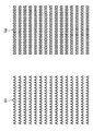
まず、図3に示すように、素材データ生成部128は、印刷データに含まれる原稿データの所定領域を切り抜いて、素材データを生成する(S102)。以下、本実施形態に係る素材データ生成部128による素材データ生成の具体例について、図4~図10を参照して説明する。
図4は、本実施形態に係る用紙画像の例を示す説明図である。図4に示す通常画像Y12は、反転振舞が「NO」である場合に用いられる用紙画像であり、反転画像Y14は、反転振舞が「YES」である場合に用いられる用紙画像である。
図5は、図4に示した用紙画像における各領域を説明するための説明図である。図5に示すように、通常画像Y12は、表面表示領域Y122と、裏面表示領域Y124とを含み、同様に反転画像Y14は、表面表示領域Y142と、裏面表示領域Y144とを含む。表面表示領域は、例えば、各用紙画像が表示オブジェクトの一部として表示操作部110に表示された際により多くの領域を占める表示面の領域である。また、裏面表示領域は、表示面の裏側の面、すなわち表示面を裏返した(捲った)面として表示される領域である。なお、以下では、印刷における表面、及び裏面との混同を避けるため、表面表示領域を視覚上の表面表示領域と呼び、裏面表示領域を視覚上の裏面表示領域と呼ぶ場合がある。
ステップS102において、素材データ生成部128は、表示オブジェクトにおける視覚上の表面表示領域と裏面表示領域に、対応する原稿データの領域を切り抜いて素材データを生成してもよい。図6は、素材データ生成部128が切り抜く原稿データの領域を示す説明図である。
図6に示す原稿データC11~C14のうち、破線で囲まれた領域が素材データ生成部128により切り抜かれる領域である。例えば、図6に示す原稿データC11の表面表示領域C1は、図5に示した通常画像Y12の表面表示領域Y122に対応する領域である。また、図6に示す原稿データC12の裏面表示領域C2は、図5に示した通常画像Y12の裏面表示領域Y124に対応する領域である。また、図6に示す原稿データC13の表面表示領域C3は、図5に示した反転画像Y14の表面表示領域Y142に対応する領域である。また、図6に示す原稿データC14の裏面表示領域C4は、図5に示した反転画像Y14の裏面表示領域Y144に対応する領域である。
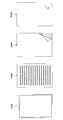
図7は、本動作例に係る印刷データに含まれる原稿データの一例を示す説明図である。本動作例に係る印刷データには、図7に示す1頁目の原稿データG1(第一の原稿データ)と、2頁目の原稿データG2(第二の原稿データ)が含まれる。
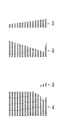
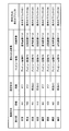
図8~10は、本実施形態に係る素材データ生成部128による素材データの生成処理を説明するための説明図である。本実施形態に係る素材データ生成部128は、図8に示す表に従って、原稿データG1から図6を参照して説明した領域C1~C4を切り抜いて、図9に示す素材データM11~M14を生成する。同様に、本実施形態に係る素材データ生成部128は、図8に示す表に従って、原稿データG2から図6を参照して説明した領域C1~C4を切り抜いて、図10に示す素材データM21~M24を生成する。
図3に戻って説明を続ける。ステップS104において、プレビュー画像生成部126は、ステップS102で生成された素材データに基づいてプレビュー画像を生成する。以下、本実施形態に係るプレビュー画像生成部126によるプレビュー画像生成の具体例について、図11、図12を参照して説明する。
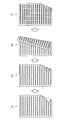
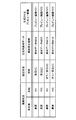
図11、図12は、本実施形態に係るプレビュー画像生成部126によるプレビュー画像生成処理を説明するための説明図である。プレビュー画像生成部126は、図11の表に示すように、振舞状況(表示面振舞、及び反転振舞)と設定状況(両面設定)に基づいて、図9,10に示した素材データからプレビュー画像の生成に用いる生成用素材データを特定する。
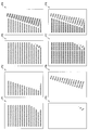
さらに、プレビュー画像生成部126は、特定された生成用素材データを、それぞれ対応する領域に整合するように加工して、図12に示すプレビュー画像P1~P8を生成する。図11、図12に示すように、両面設定が両面を示す値(長辺とじ)である場合のプレビュー画像P3、P4、P7、P8は、原稿データG1に基づく素材データと、原稿データG2に基づく素材データとが合成された画像である。
なお、上述したように、プレビュー画像生成部126は、ステップS104において、生成したプレビュー画像P1~P8を、記憶部130に記憶させてもよい。
図3に戻って説明を続ける。ステップS106において、表示制御部124は、振舞状況、及び設定状況に応じたプレビュー画像、及び用紙画像を重ねることで、表示オブジェクトを表示させる。以下、本実施形態に係る表示制御部124が表示させる表示オブジェクトの具体例について、図13、図14を参照して説明する。
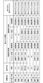
図13、図14は、本実施形態に係る表示制御部124が表示させる表示オブジェクトの具体例を説明するための説明図である。表示制御部124は、図13の表に示すように振舞状況(表示面振舞、及び反転振舞)と設定状況(両面設定)に基づいて、図12に示したプレビュー画像と、図4に示した用紙画像から、重ねられるプレビュー画像と用紙画像の組み合わせを特定する。
さらに、表示制御部124は、特定されたプレビュー画像と用紙画像とを重ねることで、図14に示す表示オブジェクトD1~D8を表示操作部110に表示させる。
図3に戻って説明を続ける。表示操作部110を介したユーザの入力に基づき、振舞状況、または設定状況に変化が生じた場合(S108においてYES)、ステップS106に戻り、表示制御部124が変化後の振舞状況、及び設定状況に応じた表示オブジェクトを表示させる。
図15は、振舞状況、及び設定状況に応じた表示オブジェクトの表示遷移例を示す説明図である。図15に示す例では、振舞状況、及び設定状況が初期状態「表示面振舞:表面、反転振舞:NO、両面設定:オフ」である場合に表示オブジェクトD1が表示される。続いて、振舞状況、及び設定状況が両面設定状態「表示面振舞:表面、反転振舞:NO、両面設定:長辺とじ」に変化すると、表示される表示オブジェクトは、表示オブジェクトD3に遷移する。さらに、振舞状況、及び設定状況が反転状態「表示面振舞:裏面、反転振舞:YES、両面設定:長辺とじ」に変化すると、表示される表示オブジェクトは、表示オブジェクトD4に遷移する。さらに、振舞状況、及び設定状況が裏面状態「表示面振舞:裏面、反転振舞:NO、両面設定:長辺とじ」に変化すると、表示される表示オブジェクトは、表示オブジェクトD7に遷移する。
図3に戻って説明を続ける。表示操作部110を介したユーザの入力に基づき、印刷が開始またはキャンセルされるまで、ステップS106~S108の処理は繰り返され、印刷が開始、またはキャンセルされる(S110においてYES)と、処理は終了する。
<1-3.第一の実施形態の効果>
以上、本発明の第一の実施形態について説明した。本実施形態によれば、ユーザは現在の両面設定をより容易に把握することが可能である。例えば、ユーザはプレビュー画面に表示された1つの表示オブジェクトを確認するだけで、印刷における表面と裏面の両方の状態を把握することが出来る。
以上、本発明の第一の実施形態について説明した。本実施形態によれば、ユーザは現在の両面設定をより容易に把握することが可能である。例えば、ユーザはプレビュー画面に表示された1つの表示オブジェクトを確認するだけで、印刷における表面と裏面の両方の状態を把握することが出来る。
<<2.第二の実施形態>>
上述した第一の実施形態では、視覚上の表面表示領域に対応する素材データと、視覚上の裏面表示領域に対応する素材データとが生成される例を説明した。これに対し、以下では、第二の実施形態として、視覚上の表面表示領域に対応する素材データが生成されない例を説明する。
上述した第一の実施形態では、視覚上の表面表示領域に対応する素材データと、視覚上の裏面表示領域に対応する素材データとが生成される例を説明した。これに対し、以下では、第二の実施形態として、視覚上の表面表示領域に対応する素材データが生成されない例を説明する。
<2-1.第二の実施形態の構成例>
本発明の第二の実施形態に係る画像形成装置は、第一の実施形態に係る画像形成装置と同様に、例えばコピー機能を有する情報処理装置である。また、第二の実施形態に係る画像形成装置は、例えばスキャナ機能、ファクシミリ機能、インターネットファクシミリ機能、及びネットワークプリンタ機能などを有してもよい。また、本発明の第二の実施形態に係る画像形成装置は、図1を参照して説明した第一の実施形態に係る画像形成装置1と一部において同様の構成を有するため、適宜省略しながら説明を行う。以下では、図16を参照して、第二の実施形態に係る画像形成装置の構成について説明する。
本発明の第二の実施形態に係る画像形成装置は、第一の実施形態に係る画像形成装置と同様に、例えばコピー機能を有する情報処理装置である。また、第二の実施形態に係る画像形成装置は、例えばスキャナ機能、ファクシミリ機能、インターネットファクシミリ機能、及びネットワークプリンタ機能などを有してもよい。また、本発明の第二の実施形態に係る画像形成装置は、図1を参照して説明した第一の実施形態に係る画像形成装置1と一部において同様の構成を有するため、適宜省略しながら説明を行う。以下では、図16を参照して、第二の実施形態に係る画像形成装置の構成について説明する。
図16は、本実施形態に係る画像形成装置の構成例を示す説明図である。図10に示すように、本実施形態に係る画像形成装置2は、例えば、表示装置20、スキャナ部12、プリンタ部14、制御部16、及び通信部18を備える。図16に示す構成のうち、図1に示した各構成と実質的に同様の構成については同一の符号を付してあるため、説明を省略する。
図16に示す表示装置20は、制御部220の機能が図1に示す表示装置10の制御部120の機能と一部異なる点で、表示装置10と異なる。制御部220は、制御部120と同様に表示装置20の各構成を制御する。また、制御部220は、図16に示すように状況特定部122、表示制御部224、プレビュー画像生成部226、素材データ生成部228としても機能する。このうち、状況特定部122の機能は、図1を参照して説明した状況特定部122と同様であるため説明を省略する。
本実施形態に係る表示制御部224は、図1を参照して説明した表示制御部124と同様に、表示操作部110を制御して、画像形成装置2の機能に係る各種画面を表示させる。本実施形態に係る表示制御部224は、視覚上の表面表示領域と、視覚上の裏面表示領域のそれぞれにおいて、用紙画像とプレビュー画像を重ねることで表示オブジェクトを表示させる点で、表示制御部124と異なる。
図17は、本実施形態に係る用紙画像とプレビュー画像の例を示す説明図である。図17に示す通常画像Y202は、表面表示領域において重ねられる用紙画像の例である。また、図17に示すプレビュー画像P202は、表面表示領域において重ねられるプレビュー画像の例である。ここで、表面表示領域において重ねられるプレビュー画像P202は、表面表示領域に対応する原稿データそのものであってもよい。
また、図17に示す反転画像Y204は、裏面表示領域において重ねられる用紙画像の例である。また、図17に示すプレビュー画像P204は、裏面表示領域において重ねられるプレビュー画像の例である。
図18は表示制御部224が表示させるプレビュー画面、及び表示オブジェクトの一例について説明するための説明図である。図18に示すように、プレビュー画面U200は、印刷結果における印刷媒体を示す表示オブジェクトD200を含む。また、図18に示すように、プレビュー画面U200は、ボタンU201~U204を含んでもよい。なお、図18に示すボタンU201~U204の機能は、図2に示したボタンU101~U104の機能と同様であるため、説明を省略する。
表示制御部224は、例えば図17に示した通常画像Y202、プレビュー画像P202、反転画像Y204、及びプレビュー画像P204を、上記の順番で重ねることで、図18に示す表示オブジェクトD200を表示する。表示された表示オブジェクトD200の機能、及び効果は、図2を参照して説明した表示オブジェクトD100と同様であるため説明を省略する。
また、表示制御部224は、視覚上の表面表示領域、及び視覚上の裏面表示領域のそれぞれについて、重ねられるプレビュー画像と用紙画像とを特定してもよい。
例えば、表示制御部224は、両面設定(設定状況)と、振舞状況に基づいて、印刷データに含まれる複数の原稿データから、視覚上の裏面表示領域において重ねられる一のプレビュー画像(原稿データ)を特定してもよい。また、表示制御部224は、両面設定(設定状況)と、振舞状況に基づいて、記憶部130に記憶される複数のプレビュー画像から、視覚上の裏面表示領域において用紙画像と重ねられる一のプレビュー画像を特定してもよい。
また、本実施形態では、視覚上の表面表示領域において重ねられる用紙画像は図17に示す通常画像Y202のみであってもよく、以後、通常画像Y202を単に通常画像と呼ぶ場合がある。また、表示制御部224は、振舞状況に基づいて、記憶部130に記憶される複数の用紙画像から、視覚上の裏面表示領域において重ねられる一の用紙画像を特定してもよい。なお、表示制御部224による、プレビュー画像と用紙画像の具体的な特定例については、図26を参照して後述する。
プレビュー画像生成部226は、図1を参照して説明したプレビュー画像生成部126と同様にプレビュー画像を生成する。本実施形態に係るプレビュー画像生成部226は、後述する素材データ生成部228により生成される裏面表示領域に対応する素材データに基づいて、裏面表示領域に対応するプレビュー画像を生成してもよい。
なお、プレビュー画像生成部226により生成されるプレビュー画像の具体例については、図23,24を参照して後述する。
素材データ生成部228は、図1を参照して説明した素材データ生成部128と同様に、印刷データに含まれる原稿データの所定領域を切り抜いて、素材データを生成する。本実施形態に係る素材データ生成部228は、裏面表示領域に対応する素材データのみを生成してもよい。なお、素材データ生成部228が切り抜く領域の例、及び素材データ生成部228により生成される素材データの具体例については、後述する。
<2-2.第二の実施形態の動作例>
以上、本実施形態の構成例について説明した。続いて、本実施形態の動作、特に表示装置20によるプレビュー画面の表示に係る動作の一例について、図3と図19~27を参照して説明する。なお、本実施形態の動作は、第一の実施形態の動作と一部において同様であるため、適宜省略しながら説明を行う。
以上、本実施形態の構成例について説明した。続いて、本実施形態の動作、特に表示装置20によるプレビュー画面の表示に係る動作の一例について、図3と図19~27を参照して説明する。なお、本実施形態の動作は、第一の実施形態の動作と一部において同様であるため、適宜省略しながら説明を行う。
以下では、第一の実施形態に係る動作例と同様に、図7に示した印刷データに含まれる原稿データを例に具体的な動作を説明する。また、本実施形態に係る動作の全体的な流れは、図3に示したフローチャートと同様であるため、以下、図3を参照しながら、説明を行う。
まず、図3に示すように素材データ生成部228は、印刷データに含まれる原稿データの所定領域を切り抜いて、素材データを生成する(S102)。以下、本実施形態に係る素材データ生成部228による素材データ生成の具体例について、図19~図22を参照して説明する。
図19は、本実施形態に係る裏面表示領域に対応する用紙画像の例を示す説明図である。図19に示す反転画像Y21は、反転振舞が「NO」である場合に裏面表示領域において用いられる用紙画像であり、反転画像Y22は、反転振舞が「YES」である場合に裏面表示領域において用いられる用紙画像である。
図19に示す反転画像Y21、及び反転画像Y22のうち、背景領域Y212、及び背景領域Y222の色は、図18に示したプレビュー画面U200の背景領域U205の色と同一であってもよい。係る構成により、反転画像Y21、及び反転画像Y22を重ねて表示される表示オブジェクトと、背景領域U205との境界が整合し、ユーザに違和感を与えない。
図20は、図19に示した用紙画像における各領域を説明するための説明図である。図20に示すように、反転画像Y21は裏面表示領域Y214を含み、反転画像Y22は、裏面表示領域Y224を含む。ステップS102において、本実施形態に係る素材データ生成部228は、表示オブジェクトにおける視覚上の裏面表示領域に対応する原稿データの領域を切り抜いて素材データを生成する。図21は、素材データ生成部228が切り抜く原稿データの領域を示す説明図である。
図21に示す原稿データC25、C26のうち、破線で囲まれた領域が素材データ生成部228により切り抜かれる領域である。例えば、図21に示す原稿データC25の裏面表示領域C5は、図20に示した反転画像Y21の裏面表示領域Y214に対応する領域である。また、図21に示す原稿データC26の裏面表示領域C6は、図20に示した反転画像Y22の裏面表示領域Y224に対応する領域である。
図22、図23は、本実施形態に係る素材データ生成部228による素材データの生成処理を説明するための説明図である。本実施形態に係る素材データ生成部228は、図22に示す表に従って、原稿データG1から図21を参照して説明した領域C5、C6を切り抜いて、図23に示す素材データM15、M16を生成する。同様に、本実施形態に係る素材データ生成部228は、図22に示す表に従って、原稿データG2から図21を参照して説明した領域C5、C6を切り抜いて、図23に示す素材データM25、M26を生成する。
図22、図23に示すように、本実施形態に係る素材データ生成部228により生成される素材データは、裏面表示領域に対応する素材データのみであり、図8~10を参照して説明した第一の実施形態で生成される素材データよりも少ない。
図3に戻って説明を続ける。ステップS104において、プレビュー画像生成部226は、ステップS102で生成された素材データに基づいてプレビュー画像を生成する。以下、本実施形態に係るプレビュー画像生成部226によるプレビュー画像生成の具体例について、図24、図25を参照して説明する。
図24、図25は、本実施形態に係るプレビュー画像生成部226によるプレビュー画像生成処理を説明するための説明図である。プレビュー画像生成部226は、図24の表に示すように、振舞状況(表示面振舞、及び反転振舞)と設定状況(両面設定)に基づいて、図23に示した素材データからプレビュー画像の生成に用いる生成用素材データを特定する。
さらに、プレビュー画像生成部226は、特定された生成用素材データを、それぞれ素材データに対応する用紙画像の裏面表示領域に整合するように加工して、図25に示すプレビュー画像P21~P24を生成する。図24、図25に示すように、本実施形態に係るプレビュー画像生成部226により生成されるプレビュー画像は、裏面表示領域に対応する素材データのみから生成され、図11、図12を参照して説明した第一の実施形態で生成されるプレビュー画像よりも少ない。
なお、プレビュー画像生成部226は、ステップS104において、生成したプレビュー画像P21~P24を、記憶部130に記憶させてもよい。
図3に戻って説明を続ける。ステップS106において、表示制御部224は、振舞状況、及び設定状況に応じたプレビュー画像、及び用紙画像を重ねることで、表示オブジェクトを表示させる。以下、本実施形態に係る表示制御部224が表示させる表示オブジェクトの具体例について、図26、図27を参照して説明する。
図26、図27は、本実施形態に係る表示制御部224が表示させる表示オブジェクトの具体例を説明するための説明図である。表示制御部224は、図26の表に示すように振舞状況(表示面振舞、及び反転振舞)と設定状況(両面設定)に基づいて、表面表示領域と裏面表示領域のそれぞれにおいて、重ねられるプレビュー画像と用紙画像の組み合わせを特定する。表面表示領域において重ねられるプレビュー画像は印刷データに含まれる原稿データG1、G2から特定される。また、表面表示領域において重ねられる用紙画像は、上述したように通常画像(図17に示した通常画像Y202)である。さらに、裏面表示領域において重ねられるプレビュー画像は、図25に示したプレビュー画像P21~P24から特定され、裏面表示領域において重ねられる用紙画像は、図19に示した反転画像Y21、反転画像Y22から特定される。
さらに、表示制御部224は、特定されたプレビュー画像と用紙画像とを重ねることで、図27に示す表示オブジェクトD21~D28を表示操作部110に表示させる。
図3に戻って説明を続ける。表示操作部110を介したユーザの入力に基づき、振舞状況、または設定状況に変化が生じた場合(S108においてYES)、ステップS106に戻り、表示制御部224が変化後の振舞状況、及び設定状況に応じた表示オブジェクトを表示させる。
図28は、振舞状況、及び設定状況に応じた表示オブジェクトの表示遷移例を示す説明図である。図28に示す例では、振舞状況、及び設定状況が初期状態「表示面振舞:表面、反転振舞:NO、両面設定:オフ」である場合に表示オブジェクトD21が表示される。続いて、振舞状況、及び設定状況が両面設定状態「表示面振舞:表面、反転振舞:NO、両面設定:長辺とじ」に変化すると、表示される表示オブジェクトは、表示オブジェクトD23に遷移する。さらに、振舞状況、及び設定状況が反転状態「表示面振舞:裏面、反転振舞:YES、両面設定:長辺とじ」に変化すると、表示される表示オブジェクトは、表示オブジェクトD24に遷移する。さらに、振舞状況、及び設定状況が裏面状態「表示面振舞:裏面、反転振舞:NO、両面設定:長辺とじ」に変化すると、表示される表示オブジェクトは、表示オブジェクトD27に遷移する。
図3に戻って説明を続ける。表示操作部110を介したユーザの入力に基づき、印刷が開始またはキャンセルされるまで、ステップS106~S108の処理は繰り返され、印刷が開始、またはキャンセルされる(S110においてYES)と、処理は終了する。
<2-3.第二の実施形態の効果>
以上、本発明の第二の実施形態について説明した。上述した第二の実施形態によれば、第一の実施形態と同様に、ユーザは現在の両面設定をより容易に把握することが可能である。
以上、本発明の第二の実施形態について説明した。上述した第二の実施形態によれば、第一の実施形態と同様に、ユーザは現在の両面設定をより容易に把握することが可能である。
また、本実施形態において生成される素材データ、及びプレビュー画像は、第一の実施形態において生成される素材データ、及びプレビュー画像よりも少ないため、図3のステップS102,S104における処理量と記憶されるデータ量を削減する効果がある。
また、本実施形態によれば、表面表示領域と裏面表示領域で表示オブジェクトの表示に用いられるプレビュー画像が異なるため、表面表示領域に対応するプレビュー画像のみを所定操作(ピンチ操作等)により拡大または縮小させる、という機能も実現可能である。
<<3.変形例>
以上、本発明の実施形態を説明した。以下では、本発明の幾つかの変形例を説明する。なお、以下に説明する各変形例は、単独で各実施形態に適用されてもよいし、組み合わせで各実施形態に適用されてもよい。また、各変形例は、上記実施形態で説明した構成に代えて適用されてもよいし、上記実施形態で説明した構成に対して追加的に適用されてもよい。
以上、本発明の実施形態を説明した。以下では、本発明の幾つかの変形例を説明する。なお、以下に説明する各変形例は、単独で各実施形態に適用されてもよいし、組み合わせで各実施形態に適用されてもよい。また、各変形例は、上記実施形態で説明した構成に代えて適用されてもよいし、上記実施形態で説明した構成に対して追加的に適用されてもよい。
<3-1.変形例1>
上記実施形態では、素材データ生成部により切り抜かれる原稿データの所定領域が空白ではない例を説明したが、原稿データによっては、当該所定領域が空白であり得る。係る場合、印刷設定に基づいて印刷されるべき面に対応する表示領域が空白に表示されて、ユーザが現在の両面設定が把握できない恐れがある。以下では、素材データ生成部により切り抜かれる原稿データの所定領域が空白である場合に行われる処理について、変形例1として説明する。
上記実施形態では、素材データ生成部により切り抜かれる原稿データの所定領域が空白ではない例を説明したが、原稿データによっては、当該所定領域が空白であり得る。係る場合、印刷設定に基づいて印刷されるべき面に対応する表示領域が空白に表示されて、ユーザが現在の両面設定が把握できない恐れがある。以下では、素材データ生成部により切り抜かれる原稿データの所定領域が空白である場合に行われる処理について、変形例1として説明する。
例えば、表示制御部は、両面設定に基づいて印刷されるべき面に対応する原稿データの所定領域が空白である場合には、当該原稿データの所定領域の代わりに、ダミーのデータを含む表示オブジェクトを表示させてもよい。例えば、素材データ生成部が、原稿データから所定領域を切り抜いて素材データを生成する際に、当該所定領域が空白であるか否かを判定し、空白である場合には、ダミーの原稿データから所定領域を切り抜いて、素材データを生成してもよい。ダミーの原稿データは、例えば全体が文字や絵、所定色等で埋められた原稿データであってもよい。係る場合、表示制御部は、ダミーの原稿データから生成される素材データを含むプレビュー画像をダミーのデータとして含む表示オブジェクトを表示させ得る。
また、同様の効果を持つダミーのデータとして、ダミーの用紙画像、またはダミーのプレビュー画像が予め生成され、記憶部に記憶されていてもよい。係る場合、表示制御部は、両面設定に基づいて印刷されるべき面に対応する原稿データの所定領域が空白である場合に、ダミーの用紙画像、またはダミーのプレビュー画像を重ねることで、表示オブジェクトを表示させてもよい。
また、表示制御部は、両面設定に基づいて印刷されるべき面に対応する原稿データの所定領域が空白である場合に、当該所定領域を拡大した拡大所定領域を含む表示オブジェクトを表示させてもよい。例えば、表示装置の制御部は、用紙画像の裏返される(捲られる)部分を、現在の振舞状況に基づく用紙画像よりも大きくする(大きく裏返す)ことで、対応する原稿データの領域が拡大され、拡大所定領域が特定されてもよい。また、原稿データにおける拡大所定領域が空白でなくなるまで、拡大所定領域は拡大されてもよい。
なお、上述した、原稿データにおける所定領域が空白であるか否かの判定は、例えば、原稿データにおける所定領域の空白率が所定値以上である場合に空白であると判定することにより行われてもよい。
本変形例において上述したいずれかの構成により、素材データ生成部により切り抜かれる原稿データの所定領域が空白であっても、ユーザは現在の両面設定を把握することが可能である。
<3-2.変形例2>
上記実施形態では、表示制御部が、記憶部に記憶された用紙画像とプレビュー画像から、特定した用紙画像とプレビュー画像を重ねることで、表示オブジェクトを表示させる例を説明したが、本発明は係る例に限定されない。
上記実施形態では、表示制御部が、記憶部に記憶された用紙画像とプレビュー画像から、特定した用紙画像とプレビュー画像を重ねることで、表示オブジェクトを表示させる例を説明したが、本発明は係る例に限定されない。
例えば、表示制御部が素材データ生成部、及びプレビュー画像生成部の機能を有し、振舞状況と設定状況に応じて動的にプレビュー画像を生成して、表示オブジェクトを表示させてもよい。
また、例えば、表示装置は、用紙画像とプレビュー画像を合成して、表示オブジェクトを生成する表示オブジェクト生成部をさらに備えてもよい。また、表示オブジェクト生成部は、生成した表示オブジェクトを予め記憶部に記憶させ、表示制御部は、振舞状況と設定状況に応じて、記憶部から表示させる表示オブジェクトを特定してもよい。
係る構成によれば、表示制御部は、振舞状況または設定状況に変化が生じた場合に、変化に応じた表示オブジェクトをより高速に表示させることが可能となる。
<3-3.変形例3>
上記実施形態では、反転振舞の値は「YES」または「NO」である例を説明したが、本発明は係る例に限定されない。例えば、反転振舞は3種類以上の値であってもよく、値に応じて、用紙画像、または表示オブジェクトにおける視覚上の表面表示領域と裏面表示領域の割合が変化してもよい。
上記実施形態では、反転振舞の値は「YES」または「NO」である例を説明したが、本発明は係る例に限定されない。例えば、反転振舞は3種類以上の値であってもよく、値に応じて、用紙画像、または表示オブジェクトにおける視覚上の表面表示領域と裏面表示領域の割合が変化してもよい。
係る構成によれば、振舞状況の変化による表示オブジェクトの表示遷移が、より滑らかな遷移となる。
<<4.ハードウェア構成例>>
以上、本発明の各実施形態と各変形例を説明した。上述した状況特定処理、表示制御処理、プレビュー画像生成処理、素材データ生成処理、などの情報処理は、ソフトウェアと、以下に説明する画像形成装置1のハードウェアとの協働により実現される。
以上、本発明の各実施形態と各変形例を説明した。上述した状況特定処理、表示制御処理、プレビュー画像生成処理、素材データ生成処理、などの情報処理は、ソフトウェアと、以下に説明する画像形成装置1のハードウェアとの協働により実現される。
図29は、画像形成装置1のハードウェア構成例を示す説明図である。図29に示したように、画像形成装置1は、CPU(Central Processing Unit)151と、ROM(Read Only Memory)152と、RAM(Random Access Memory)153と、入出力装置154と、ストレージ装置155と、スキャナ装置156と、プリンタ装置157と、通信装置158とを備える。
CPU151は、演算処理装置及び制御装置として機能し、各種プログラムに従って画像形成装置1内の動作全般を制御する。また、CPU151は、マイクロプロセッサであってもよい。ROM152は、CPU151が使用するプログラムや演算パラメータなどを記憶する。RAM153は、CPU151の実行において使用するプログラムや、その実行において適宜変化するパラメータなどを一時記憶する。これらはCPUバスなどから構成されるホストバスにより相互に接続されている。主に、CPU151、ROM152及びRAM153とソフトウェアとの協働により、制御部120、制御部16の機能が実現される。
入出力装置154は、タッチパネルなどユーザが情報を入力するための入力手段と、撮像された画像や生成された画像などを表示する表示手段を含む。入力手段は、ユーザによる入力に基づいて入力信号を生成し、CPU151に出力する入力制御回路などから構成されている。入力手段は、マウス、キーボード、タッチパネル、ボタン、マイクロフォン、スイッチ及びレバーなどを含んでもよい。画像形成装置1のユーザは、該入出力装置154を操作することにより、画像形成装置1に対して各種のデータを入力したり処理動作を指示したりすることができる。また、出力手段はスピーカ及びヘッドホンなどの音声出力装置を含み、音声出力装置は、音声データなどを音声に変換して出力する。入出力装置154は、図1を参照して説明した表示操作部110に対応する。
ストレージ装置155は、データ格納用の装置である。ストレージ装置155は、記憶媒体、記憶媒体にデータを記録する記録装置、記憶媒体からデータを読み出す読出し装置及び記憶媒体に記録されたデータを削除する削除装置などを含んでもよい。ストレージ装置155は、CPU151が実行するプログラムや各種データを格納する。
スキャナ装置156は、ADF(Auto Document Feeder)と原稿台を備え、原稿用紙から画像情報を読み取る。スキャナ装置156は、図1を参照して説明したスキャナ部12に対応する。プリンタ装置157は、画像データに従って用紙に印刷する。プリンタ装置157は、図1を参照して説明したプリンタ部14に対応する。
通信装置158は、例えば、図1を参照して説明した通信網5等の伝送路に接続するための通信デバイスなどで構成された通信インタフェースである。また、通信装置158は、無線LAN(Local Area Network)対応通信装置、LTE(Long Term Evolution)対応通信装置、有線による通信を行うワイヤー通信装置、またはブルートゥース(登録商標)通信装置を含んでもよい。通信装置158は、図1を参照して説明した通信部18に対応する。
なお上記では画像形成装置1のハードウェア構成を説明したが、画像形成装置2も、画像形成装置1と同様に、CPU151、ROM152およびRAM153などに相当するハードウェアを有する。そして、画像形成装置2のハードウェアとソフトウェアとの協働により、例えば制御部220の機能等が実現される。
<<5.むすび>>
以上説明したように、本発明の実施形態によれば、ユーザが現在の両面設定をより容易に把握することが可能である。
以上説明したように、本発明の実施形態によれば、ユーザが現在の両面設定をより容易に把握することが可能である。
以上、添付図面を参照しながら本発明の好適な実施形態について詳細に説明したが、本発明はかかる例に限定されない。本発明の属する技術の分野における通常の知識を有する者であれば、特許請求の範囲に記載された技術的思想の範疇内において、各種の変更例または修正例に想到し得ることは明らかであり、これらについても、当然に本発明の技術的範囲に属するものと了解される。
上記実施形態では、上述した表示装置10、及び表示装置20の各機能を、画像形成装置1、及び画像形成装置2が有する例を説明したが、本発明は係る例に限定されない。上述した表示装置10、及び表示装置20の各機能を他の装置が有してもよく、例えば、図1を参照して説明した通信網5に接続された不図示の情報処理装置が、上述した表示装置10、または表示装置20の状況特定部、表示制御部、プレビュー画像生成部、素材データ生成部の機能を有してもよい。なお、通信網5に接続された当該不図示の情報処理装置は、例えばPC(Personal Computer)、タブレットPC、スマートフォン等の情報処理装置であってもよい。
また、上記実施形態では、両面設定における両面印刷を示す値として、「長辺とじ」のみを説明したが、両面設定における両面印刷を示す値は「短辺とじ」を含んでもよい。
また、画像形成装置1に内蔵されるCPU151、ROM152、及びRAM153などのハードウェアに、上述した画像形成装置1、及び画像形成装置2の機能を発揮させるためのコンピュータプログラムも作成可能である。また、該コンピュータプログラムを記録させた記録媒体も提供される。
1 画像形成装置
5 通信網
10 表示装置
12 スキャナ部
14 プリンタ部
16 制御部
18 通信部
110 表示操作部
120 制御部
122 状況特定部
124 表示制御部
126 プレビュー画像生成部
128 素材データ生成部
130 記憶部
5 通信網
10 表示装置
12 スキャナ部
14 プリンタ部
16 制御部
18 通信部
110 表示操作部
120 制御部
122 状況特定部
124 表示制御部
126 プレビュー画像生成部
128 素材データ生成部
130 記憶部
Claims (15)
- 複数の原稿データを含む印刷データの印刷に係る両面設定を特定する設定特定部と、
前記印刷データと前記両面設定に基づいて、印刷における表面である第一の面、及び印刷における裏面である第二の面が合成された表示オブジェクトを表示させる表示制御部と、
を備える情報処理装置。 - 前記両面設定が両面印刷を示す値である場合に前記表示制御部が表示させる前記表示オブジェクトは、前記第一の面に対応する原稿データの所定領域、及び前記第二の面に対応する原稿データの所定領域を含む、請求項1に記載の情報処理装置。
- 前記表示制御部は、印刷結果を示すプレビュー画像と、印刷用紙を示す用紙画像を重ねることで、前記表示オブジェクトを表示させる、請求項1に記載の情報処理装置。
- 前記表示制御部は、前記両面設定に基づいて、複数のプレビュー画像から、前記用紙画像と重ねられるプレビュー画像を特定する、請求項3に記載の情報処理装置。
- 前記表示制御部は、前記表示オブジェクトの振舞に係る振舞状況にさらに基づいて、前記複数のプレビュー画像から、前記用紙画像と重ねられるプレビュー画像を特定する、請求項4に記載の情報処理装置。
- 前記印刷データに含まれる前記原稿データから所定領域を切り抜いて生成される素材データに基づいて、前記プレビュー画像を生成するプレビュー画像生成部をさらに備える、請求項3に記載の情報処理装置。
- 前記プレビュー画像生成部は、前記第一の面に対応する原稿データから生成される前記素材データと、前記第二の面に対応する原稿データから生成される前記素材データと、を合成して、前記プレビュー画像を生成する、請求項6に記載の情報処理装置。
- 前記表示制御部は、視覚上の表面表示領域、及び視覚上の裏面表示領域のそれぞれにおいて、前記用紙画像と前記プレビュー画像を重ねることで、前記表示オブジェクトを表示させる、請求項3に記載の情報処理装置。
- 前記表示制御部は、前記両面設定に基づいて、複数のプレビュー画像から、前記視覚上の裏面表示領域において前記用紙画像と重ねられるプレビュー画像を特定する、請求項8に記載の情報処理装置。
- 前記表示制御部は、前記表示オブジェクトの振舞に係る振舞状況にさらに基づいて、前記複数のプレビュー画像から、前記視覚上の裏面表示領域において前記用紙画像と重ねられるプレビュー画像を特定する、請求項9に記載の情報処理装置。
- 前記複数のプレビュー画像を記憶する、記憶部をさらに備える、請求項4に記載の情報処理装置。
- 前記両面設定が片面印刷を示す値である場合に前記表示制御部が表示させる前記表示オブジェクトは、前記第一の面に対応する原稿データの少なくとも一部の領域を含み、前記第一の面に対応する原稿データ以外の、前記印刷データに含まれる原稿データの領域を含まない、請求項1に記載の情報処理装置。
- 前記表示制御部は、前記両面設定に基づいて印刷されるべき面に対応する原稿データの前記所定領域が空白である場合に、ダミーのデータを含む表示オブジェクトを表示させる、請求項2に記載の情報処理装置。
- 前記表示制御部は、前記両面設定に基づいて印刷されるべき面に対応する原稿データの前記所定領域が空白である場合に、前記所定領域を拡大した拡大所定領域を含む表示オブジェクトを表示させる、請求項2に記載の情報処理装置。
- コンピュータに、
複数の原稿データを含む印刷データの印刷に係る両面設定を特定する設定特定機能と、
前記印刷データと前記両面設定に基づいて、印刷における表面である第一の面、及び印刷における裏面である第二の面が合成された表示オブジェクトを表示させる表示制御機能と、
を実現させるための、プログラムを記録したコンピュータ読み取り可能な記録媒体。
Applications Claiming Priority (2)
| Application Number | Priority Date | Filing Date | Title |
|---|---|---|---|
| JP2016-021094 | 2016-02-05 | ||
| JP2016021094A JP2017139710A (ja) | 2016-02-05 | 2016-02-05 | 情報処理装置、及びプログラム |
Publications (1)
| Publication Number | Publication Date |
|---|---|
| WO2017134863A1 true WO2017134863A1 (ja) | 2017-08-10 |
Family
ID=59500994
Family Applications (1)
| Application Number | Title | Priority Date | Filing Date |
|---|---|---|---|
| PCT/JP2016/080432 Ceased WO2017134863A1 (ja) | 2016-02-05 | 2016-10-13 | 情報処理装置、及び記録媒体 |
Country Status (2)
| Country | Link |
|---|---|
| JP (1) | JP2017139710A (ja) |
| WO (1) | WO2017134863A1 (ja) |
Citations (5)
| Publication number | Priority date | Publication date | Assignee | Title |
|---|---|---|---|---|
| JP2004094955A (ja) * | 2001-10-26 | 2004-03-25 | Ricoh Co Ltd | 文書管理装置、文書管理制御方法及び文書管理制御プログラム |
| JP2008207527A (ja) * | 2007-02-28 | 2008-09-11 | Kyocera Mita Corp | 画像形成装置,印刷プレビュー用プログラム |
| JP2008225808A (ja) * | 2007-03-13 | 2008-09-25 | Kyocera Mita Corp | 画像形成装置,印刷プレビュー用プログラム |
| JP2009296370A (ja) * | 2008-06-05 | 2009-12-17 | Sharp Corp | 情報処理装置及びプログラム |
| JP2009302759A (ja) * | 2008-06-11 | 2009-12-24 | Kyocera Mita Corp | 画像形成装置 |
-
2016
- 2016-02-05 JP JP2016021094A patent/JP2017139710A/ja active Pending
- 2016-10-13 WO PCT/JP2016/080432 patent/WO2017134863A1/ja not_active Ceased
Patent Citations (5)
| Publication number | Priority date | Publication date | Assignee | Title |
|---|---|---|---|---|
| JP2004094955A (ja) * | 2001-10-26 | 2004-03-25 | Ricoh Co Ltd | 文書管理装置、文書管理制御方法及び文書管理制御プログラム |
| JP2008207527A (ja) * | 2007-02-28 | 2008-09-11 | Kyocera Mita Corp | 画像形成装置,印刷プレビュー用プログラム |
| JP2008225808A (ja) * | 2007-03-13 | 2008-09-25 | Kyocera Mita Corp | 画像形成装置,印刷プレビュー用プログラム |
| JP2009296370A (ja) * | 2008-06-05 | 2009-12-17 | Sharp Corp | 情報処理装置及びプログラム |
| JP2009302759A (ja) * | 2008-06-11 | 2009-12-24 | Kyocera Mita Corp | 画像形成装置 |
Also Published As
| Publication number | Publication date |
|---|---|
| JP2017139710A (ja) | 2017-08-10 |
Similar Documents
| Publication | Publication Date | Title |
|---|---|---|
| JP4891102B2 (ja) | 画像形成装置,印刷プレビュー用プログラム | |
| US10237427B2 (en) | Image forming system, remote terminal, image forming apparatus, and recording medium | |
| JP2008226050A (ja) | 画像処理装置、プログラムおよびプレビュー画像表示方法 | |
| JP2004271512A5 (ja) | ||
| JP2013134387A (ja) | 表示画像の操作システム、それを構成する画像表示装置、及びその制御方法 | |
| JP2012174183A (ja) | プリンタドライバプログラム、印刷制御装置および印刷制御装置の制御方法 | |
| JP2009177526A (ja) | 画像処理装置 | |
| JP5061054B2 (ja) | 画像形成装置,プレビュー画像表示プログラム | |
| JP4942688B2 (ja) | 画像形成装置,印刷プレビュー画像表示プログラム | |
| US20090190151A1 (en) | Image forming apparatus | |
| JP2010167698A5 (ja) | ||
| JP2008306469A (ja) | 画像形成装置 | |
| WO2017134863A1 (ja) | 情報処理装置、及び記録媒体 | |
| JP5070148B2 (ja) | 画像形成装置,印刷プレビュー画像表示プログラム | |
| JP7840919B2 (ja) | 画像形成システム | |
| JP2008225808A (ja) | 画像形成装置,印刷プレビュー用プログラム | |
| JP4949076B2 (ja) | 画像形成装置,印刷プレビュー用プログラム | |
| JP6693244B2 (ja) | 情報処理装置、及びプログラム | |
| JP5257377B2 (ja) | 画像処理装置の操作パネル及び該パネルを備えた画像処理装置 | |
| JP5673334B2 (ja) | 画像データ処理装置、画像データ処理方法およびコンピュータプログラム | |
| JP4842158B2 (ja) | 画像形成装置,印刷プレビュー用プログラム | |
| JP2008179037A (ja) | 画像形成装置,印刷プレビュー用プログラム | |
| JP6607117B2 (ja) | 情報処理装置、及びプログラム | |
| JP2011171841A (ja) | 画像処理装置、画像形成装置、制御プログラム、記録媒体 | |
| WO2017168801A1 (ja) | 情報処理装置、及び記録媒体 |
Legal Events
| Date | Code | Title | Description |
|---|---|---|---|
| 121 | Ep: the epo has been informed by wipo that ep was designated in this application |
Ref document number: 16889346 Country of ref document: EP Kind code of ref document: A1 |
|
| DPE1 | Request for preliminary examination filed after expiration of 19th month from priority date (pct application filed from 20040101) | ||
| NENP | Non-entry into the national phase |
Ref country code: DE |
|
| 122 | Ep: pct application non-entry in european phase |
Ref document number: 16889346 Country of ref document: EP Kind code of ref document: A1 |