WO2017134850A1 - モータ - Google Patents
モータ Download PDFInfo
- Publication number
- WO2017134850A1 WO2017134850A1 PCT/JP2016/074850 JP2016074850W WO2017134850A1 WO 2017134850 A1 WO2017134850 A1 WO 2017134850A1 JP 2016074850 W JP2016074850 W JP 2016074850W WO 2017134850 A1 WO2017134850 A1 WO 2017134850A1
- Authority
- WO
- WIPO (PCT)
- Prior art keywords
- refrigerant
- refrigerant passage
- coil
- stator core
- passage
- Prior art date
- Legal status (The legal status is an assumption and is not a legal conclusion. Google has not performed a legal analysis and makes no representation as to the accuracy of the status listed.)
- Ceased
Links
Images




Classifications
-
- H—ELECTRICITY
- H02—GENERATION; CONVERSION OR DISTRIBUTION OF ELECTRIC POWER
- H02K—DYNAMO-ELECTRIC MACHINES
- H02K1/00—Details of the magnetic circuit
- H02K1/06—Details of the magnetic circuit characterised by the shape, form or construction
- H02K1/12—Stationary parts of the magnetic circuit
- H02K1/20—Stationary parts of the magnetic circuit with channels or ducts for flow of cooling medium
Definitions
- This invention relates to a motor.
- Japanese Utility Model Laid-Open No. 3-77260 discloses an electric motor cooling device for the purpose of realizing downsizing and increasing the cooling effect by directly cooling the vicinity of the opening of the slot.
- Patent Document 1 discloses an electric motor cooling device for the purpose of realizing downsizing and increasing the cooling effect by directly cooling the vicinity of the opening of the slot.
- the electric apparatus cooling device disclosed in Patent Document 1 includes a cooling pipe that is provided in an opening of a slot and into which a cooling medium such as cooling oil or cooling water flows.
- an object of the present invention is to solve the above-described problems and to provide a motor having excellent cooling efficiency.
- a motor according to the present invention has an annular yoke portion and a plurality of tooth portions extending radially inward from the yoke portion and spaced apart in the circumferential direction, and between adjacent tooth portions.
- a space adjacent to the outside in the radial direction of the yoke portion is referred to as an outer peripheral region, and a space in the slot is referred to as an inner peripheral region.
- the motor is supplied with a refrigerant through a route that avoids the outer peripheral region, the first refrigerant passage that flows the refrigerant to the inner peripheral region, the second refrigerant passage that flows the refrigerant to the outer peripheral region, the first refrigerant passage, and the second refrigerant passage.
- a third refrigerant passage that communicates between the refrigerant passages and guides the refrigerant after flowing through the first refrigerant passage to the second refrigerant passage;
- a motor with excellent cooling efficiency can be provided.
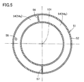
- FIG. 5 is a cross-sectional view showing a refrigerant passage forming member along the line VV in FIG. 2.
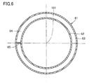
- FIG. 3 is a cross-sectional view showing a refrigerant passage forming member along the line VI-VI in FIG. 2.
- FIG. 3 is a cross-sectional view showing a refrigerant passage forming member along the line VII-VII in FIG. 2. It is sectional drawing which expands partially and shows the motor in Embodiment 2 of this invention. It is a perspective view which shows the motor in Embodiment 3 of this invention.
- FIG. 1 is a perspective view showing a motor according to Embodiment 1 of the present invention.
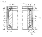
- FIG. 2 is a cross-sectional view showing the motor in FIG.
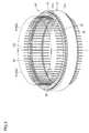
- FIG. 3 is a perspective view showing the internal structure of the motor in FIG.
- FIG. 4 is a cross-sectional view showing the motor in FIG. 3 partially enlarged.
- a motor 10 according to Embodiment 1 of the present invention is for a machine tool, and is used, for example, as a motor that rotationally drives a spindle of a machining center.
- the motor 10 includes a rotor (not shown) and a stator 20 disposed with a gap (gap) provided on the outer periphery of the rotor.
- a rotor (not shown) is driven to rotate about a central axis 101 indicated by an imaginary line.
- the stator 20 has a stator core 21 and a coil 31.
- the stator core 21 as a whole has a cylindrical shape centered on the central axis 101.
- the stator core 21 is made of a magnetic material.
- Stator core 21 has end surface 21a and end surface 21b.
- the end surface 21 a and the end surface 21 b are disposed at one end and the other end of the stator core 21 in the axial direction of the central shaft 101, respectively.
- the end surface 21 a and the end surface 21 b extend in a plane orthogonal to the central axis 101.
- a coil 31 is wound around the stator core 21.
- the stator core 21 has a yoke part 22 and a plurality of teeth parts 23 as its constituent parts (see FIG. 4).
- the yoke portion 22 has a shape that circulates in an annular shape around the central axis 101.
- the teeth part 23 has a shape that extends radially inward from the yoke part 22.
- the teeth portion 23 is opposed to the rotor with a gap at the tip that extends from the yoke portion 22.
- the plurality of tooth portions 23 are provided at intervals in the circumferential direction around the central axis 101. Slots 24 are formed between teeth portions 23 adjacent to each other in the circumferential direction.
- the coil 31 is wound around each of the plurality of tooth portions 23.
- the coil 31 is wound so as to pass through the slots 24 located on both sides of the tooth portion 23 and the end face 21a and the end face 21b.
- the portion of the coil 31 that passes over the end surface 21 a constitutes the coil end portion 32, and the portion of the coil 31 that passes over the end surface 21 b constitutes the coil end portion 33.
- the stator 20 further has a resin layer 26.
- the resin layer 26 is provided so as to fill the slot 24.
- the resin layer 26 is provided so as to cover the coil end portion 32 on the end surface 21a and to cover the coil end portion 33 on the end surface 21b.
- the stator 20 has a cylindrical shape centered on the central axis 101.
- FIG. 5 is a cross-sectional view showing the refrigerant passage forming member along the line VV in FIG.
- FIG. 6 is a cross-sectional view showing the refrigerant passage forming member along the line VI-VI in FIG.
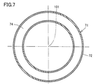
- FIG. 7 is a cross-sectional view showing the refrigerant passage forming member along the line VII-VII in FIG.
- the cooling structure provided in the motor 10 will be described in detail.
- the motor 10 includes a refrigerant passage forming member 51, a refrigerant passage forming member 61, a refrigerant passage forming member 71, and a refrigerant passage forming member 41.
- the refrigerant passage forming member 51, the refrigerant passage forming member 61, the refrigerant passage forming member 71, and the refrigerant passage forming member 41 form a refrigerant passage through which a refrigerant such as cooling water or cooling oil can flow.
- the refrigerant passage forming member 51, the refrigerant passage forming member 61, the refrigerant passage forming member 71, and the refrigerant passage forming member 41 are provided in contact with the stator 20.
- the refrigerant passage forming member 51 has a disk shape centered on the central axis 101.
- the refrigerant passage forming member 51 is provided on one end side in the axial direction of the central shaft 101 with respect to the stator 20.
- the refrigerant passage forming member 51 is provided at a position facing the end surface 21 a in the axial direction of the central shaft 101.
- the coil end portion 32 is located between the end surface 21 a and the refrigerant passage forming member 51.
- the refrigerant passage forming member 51 is provided directly above the coil end portion 32 through the resin layer 26.
- the refrigerant passage forming member 51 is provided in contact with the resin layer 26 on the end surface 21 a of the stator 20.
- the refrigerant passage forming member 51 is configured by combining a main body portion 52, a lid portion 53, a wall member 56 and a wall member 57.
- the main body 52 has a concave cross section and is provided so as to circulate around the central axis 101 in an annular shape.
- the lid 53 is provided so as to close the opening of the main body 52.
- the wall member 56 and the wall member 57 have a wall shape and are provided so as to close the concave cross section of the main body 52.
- the wall member 56 and the wall member 57 are provided apart from each other in the circumferential direction around the central axis 101.
- the refrigerant passage 54 is formed by the refrigerant passage forming member 51 configured as described above.
- the refrigerant passage 54 is provided in a region facing the coil 31 (coil end portion 32) on one side of the central shaft 101 in the axial direction.
- the refrigerant passage 54 forms an annular passage centered on the central axis 101 in a region facing the coil end portion 32.
- the refrigerant passage 54 is provided at a position shifted from the outer peripheral side region 110.
- the refrigerant passage 54 is surrounded by the main body 52 and the lid 53.
- the refrigerant passage 54 is divided into a refrigerant passage 54p and a refrigerant passage 54q by a wall member 56 and a wall member 57.
- the refrigerant passage forming member 71 has a disk shape centered on the central axis 101.
- the refrigerant passage forming member 71 is provided on the other end side in the axial direction of the central shaft 101 with respect to the stator 20.
- the refrigerant passage forming member 71 is provided at a position facing the end surface 21 b in the axial direction of the central shaft 101.
- the coil end portion 33 is located between the end surface 21 b and the refrigerant passage forming member 71.
- the refrigerant passage forming member 71 is provided directly above the coil end portion 33 through the resin layer 26.
- the refrigerant passage forming member 71 is provided in contact with the resin layer 26 on the end surface 21 b of the stator 20.
- the refrigerant passage forming member 71 is configured by combining a main body 72 and a lid 73.
- the main body 72 has a concave cross section and is provided so as to circulate around the central axis 101 in an annular shape.
- the lid 73 is provided so as to close the opening of the main body 72.
- the refrigerant passage 74 is formed by the refrigerant passage forming member 71 configured as described above.
- the refrigerant passage 74 is provided in a region facing the coil 31 (coil end portion 33) on the other side in the axial direction of the central shaft 101.
- the refrigerant passage 74 forms an annular passage centering on the central axis 101 in a region facing the coil end portion 33.
- the refrigerant passage 74 is provided at a position shifted from the outer peripheral region 110.
- the refrigerant passage 74 is surrounded by the main body portion 72 and the lid portion 73.
- the refrigerant passage forming member 61 has a cylindrical shape with the central axis 101 as the center.
- the refrigerant passage forming member 61 is provided on the outer periphery of the stator 20.
- the refrigerant passage forming member 61 is provided between the refrigerant passage forming member 51 and the refrigerant passage forming member 71 in the axial direction of the central shaft 101.
- the refrigerant passage forming member 61 is provided in contact with the stator core 21 (yoke portion 22) of the stator 20 and the resin layer 26 on the end surface 21a and the end surface 21b.
- the refrigerant passage forming member 61 is configured by combining a main body 62, a lid 63, and a wall member 65.
- the main body portion 62 has a concave cross section and is provided so as to circulate around the central axis 101 in an annular shape.
- the lid 63 is provided so as to close the opening of the main body 62.
- the wall member 65 has a wall shape and is provided so as to close the concave cross section of the main body 62.
- the refrigerant passage 64 is formed by the refrigerant passage forming member 61 configured as described above.
- the refrigerant passage 64 is provided so that the refrigerant flows through the outer peripheral side region 110.
- the refrigerant passage 64 forms an annular passage around the central axis 101 on the outer periphery of the stator 20.
- the refrigerant passage 64 is surrounded by the main body 62 and the lid 63.
- the refrigerant passage 64 is not limited to the annular passage described above, and may be provided, for example, so as to extend spirally around the central axis 101, or as a whole while reciprocating along the axial direction of the central axis 101, It may be provided so as to go around the axis of the central axis 101.
- FIG. 1 and FIG. 9 mentioned later illustration of the cover part 53 and the cover part 73 is abbreviate
- a communication hole 58 is formed in the refrigerant passage forming member 51 (main body portion 52).
- the communication hole 58 passes through the refrigerant passage forming member 51 (main body portion 52).
- the communication hole 58 is provided so as to communicate between the refrigerant passage 54q and the refrigerant passage 64.
- the refrigerant passage forming member 51, the refrigerant passage forming member 61, and the refrigerant passage forming member 71 are provided so as to surround the stator 20 from the outer peripheral side and both sides in the axial direction of the central shaft 101. .
- the stator 20, the refrigerant passage forming member 51, the refrigerant passage forming member 61, and the refrigerant passage forming member 71 have a cylindrical shape centering on the central axis 101 as a whole.
- the refrigerant passage forming member 41 is provided in the slot 24.
- the refrigerant passage forming member 41 is embedded in the resin layer 26.
- the refrigerant passage forming member 41 is provided in contact with the resin layer 26 filling the slot 24 in the stator 20.
- the refrigerant passage forming member 41 is provided in each of the plurality of slots 24.
- Each slot 24 is provided with one refrigerant passage forming member 41.
- the plurality of refrigerant passage forming members 41 are provided at intervals in the circumferential direction around the central axis 101.
- the refrigerant passage forming member 41 is made of a pipe material.
- the refrigerant passage forming member 41 extends along the axial direction of the central shaft 101.
- the refrigerant passage forming member 41 is connected to the refrigerant passage forming member 51 and the refrigerant passage forming member 71 at both ends extending along the axial direction of the central shaft 101.
- the refrigerant passage 42 is formed by the refrigerant passage forming member 41 configured as described above.
- the refrigerant passage 42 is provided so that the refrigerant flows through the inner peripheral region 120.
- the refrigerant passage 42 communicates with the refrigerant passage 54 and the refrigerant passage 74.
- a plurality of refrigerant passages 42 are formed by the plurality of refrigerant passage forming members 41, respectively.
- the plurality of refrigerant passages 42 includes a first group of refrigerant passages 42p arranged in the circumferential direction, and a second group of refrigerant passages 42q arranged in the circumferential direction in a range different from the first group of refrigerant passages 42p (see FIG. 3). See
- the first group of refrigerant passages 42p among the plurality of refrigerant passages 42 communicates with the refrigerant passage 54p of the refrigerant passage 54, and the second group of refrigerant passages 42q among the plurality of refrigerant passages 42 is connected to the refrigerant passage 54. Of these, it communicates with the refrigerant passage 54q.
- the refrigerant passage forming member 41 is not necessarily provided in all of the plurality of slots 24.
- the refrigerant passage forming member 41 is disposed in every other slot 24 among the plurality of slots 24 arranged in the circumferential direction. It may be provided.
- the flow of the refrigerant in the motor 10 will be described with reference to FIGS.
- the refrigerant is first supplied to the refrigerant passage 54p (the refrigerant flow indicated by the arrow 131).
- the refrigerant supplied to the refrigerant passage 54p is split into two from the supply position, and flows in the circumferential direction around the central axis 101 (refrigerant flow indicated by an arrow 132).
- the refrigerant flows into the first group of refrigerant passages 42p while flowing through the refrigerant passage 54p.
- the refrigerant that has flowed into the first group of refrigerant passages 42p flows through the inner peripheral side region 120 in the slot 24 (refrigerant flow indicated by an arrow 133).
- the refrigerant flows into the refrigerant passage 74 from the first group of refrigerant passages 42p and flows in the circumferential direction around the central axis 101 (refrigerant flow indicated by an arrow 134).
- the refrigerant flows into the second group of refrigerant passages 42q while flowing through the refrigerant passage 74.
- the refrigerant that has flowed into the second group of refrigerant passages 42q flows through the inner peripheral side region 120 in the slot 24 (refrigerant flow indicated by an arrow 135).
- the refrigerant flows from the second group of refrigerant passages 42q into the refrigerant passage 54q and flows in the circumferential direction around the central axis 101 (refrigerant flow indicated by an arrow 136).
- the refrigerant flows from the refrigerant passage 54q into the refrigerant passage 64 through the communication hole 58 (refrigerant flow indicated by an arrow 137).
- the refrigerant that has flowed into the refrigerant passage 64 flows in the outer peripheral side region 110 adjacent to the outer side in the radial direction of the yoke portion 22 (refrigerant flow indicated by an arrow 138).
- the refrigerant flows from one side of the wall member 65 to the other side, and is then discharged from the refrigerant passage 64 to the outside (refrigerant flow indicated by an arrow 139).
- the refrigerant sequentially flows through the refrigerant passage 54p, the first group of refrigerant passages 42p, the refrigerant passage 74, the second group of refrigerant passages 42q, the refrigerant passage 54q, and the refrigerant passage 64.
- the refrigerant passage 54p that supplies the refrigerant to the first group of refrigerant passages 42p and the refrigerant passage 74 that guides the refrigerant from the first group of refrigerant passages 42p to the second group of refrigerant passages 42q are from the outer peripheral side region 110.
- the refrigerant is supplied to the inner peripheral side region 120 through a route that avoids the outer peripheral side region 110.
- the motor 10 is cooled from the inner peripheral side region 120 that is closer to the coil 31 that is a heat generation source by the refrigerant that remains at a very low temperature because it does not pass through the outer peripheral side region 110.
- the refrigerant after flowing through the refrigerant passage 42 (first group refrigerant passage 42p and second group refrigerant passage 42q) is guided to the refrigerant passage 64 through the refrigerant passage 54q.
- the motor is cooled from the outer peripheral side region 110 using the refrigerant after the heat exchange with the coil 31 is completed in the inner peripheral side region 120.
- the motor 10 can be efficiently cooled by such a two-stage cooling process.
- the first group of refrigerant passages 42p and the second group of refrigerant passages 42q are connected in series via the refrigerant passage 74 in the cooling flow direction.
- the structure of the motor 10 according to the first embodiment of the present invention described above will be described together.
- the motor 10 according to the present embodiment has an annular yoke portion 22 and extends from the yoke portion 22 radially inward.
- a stator core 21 having a plurality of teeth portions 23 provided at intervals in the circumferential direction and forming slots 24 between adjacent tooth portions 23, and a coil 31 wound around the teeth portions 23.
- a space adjacent to the outside in the radial direction of the yoke portion 22 is referred to as an outer peripheral region 110, and a space in the slot 24 is referred to as an inner peripheral region 120.
- the refrigerant is supplied through a route that avoids the outer peripheral side region 110, and the refrigerant passage 42 as a first refrigerant passage that flows the refrigerant to the inner peripheral side region 120 and the second refrigerant passage that flows the refrigerant to the outer peripheral side region 110.
- a refrigerant passage 54q as a third refrigerant passage that communicates between the refrigerant passage 42 and the refrigerant passage 64 and guides the refrigerant after flowing through the refrigerant passage 42 to the refrigerant passage 64.
- the refrigerant passage 42 extends along the axial direction of the stator core 21.
- the refrigerant passage 64 extends along the circumferential direction of the stator core 21.
- the refrigerant passage 54q is provided in a region facing the coil 31 in the axial direction of the stator core 21.
- a plurality of refrigerant passages 42 are respectively provided in the plurality of slots 24 and communicate with the refrigerant passage 54q.
- the plurality of refrigerant passages 42 include a first group of refrigerant passages 42p arranged in the circumferential direction and a second group of refrigerant passages 42q arranged in the circumferential direction in a range different from the first group of refrigerant passages 42p.
- the motor 10 communicates between a refrigerant passage 54p as a fourth refrigerant passage for supplying refrigerant to the first group of refrigerant passages 42p, and between the first group of refrigerant passages 42p and the second group of refrigerant passages 42q.
- a refrigerant passage 74 as a fifth refrigerant passage for guiding the refrigerant after flowing through the refrigerant passage 42p of the group to the refrigerant passage 42q of the second group.
- the refrigerant passage 54q is provided in a region facing the coil 31 on one side of the stator core 21 in the axial direction.
- the refrigerant passage 54p is provided in a region facing the coil 31 on one side in the axial direction of the stator core 21, and forms an annular passage centering on the central axis of the stator core 21 together with the refrigerant passage 54q.
- the motor 10 further includes a wall member 56 and a wall member 57 that partition between the refrigerant passage 54q and the refrigerant passage 54p.
- the refrigerant passage 74 is provided in a region facing the coil 31 on the other side in the axial direction of the stator core 21, and forms an annular passage centering on the central axis of the stator core 21.
- the motor 10 according to the first embodiment of the present invention configured as described above can improve the cooling efficiency of the motor 10 by appropriately arranging the refrigerant passage around the coil 31.
- FIG. 8 is a partially enlarged cross-sectional view of the motor according to the second embodiment of the present invention.
- FIG. 8 is a diagram corresponding to FIG. 4 in the first embodiment.
- the motor in the present embodiment basically has the same structure as that of motor 10 in the first embodiment. Hereinafter, the description of the overlapping structure will not be repeated.
- coil 31 includes a first coil portion 31A and a second coil portion 31B.
- the first coil portion 31 ⁇ / b> A is wound around the tooth portion 23 at a position adjacent to the inside in the radial direction of the yoke portion 22.
- the second coil portion 31B is wound around the tooth portion 23 at a position adjacent to the radially inner side of the first coil portion 31A.
- a substantially triangular space surrounded by the first coil portion 31 ⁇ / b> A, the second coil portion 31 ⁇ / b> B, and the yoke portion 22 is formed between the adjacent tooth portions 23.
- Each slot 24 is provided with two refrigerant passage forming members 41 (41A, 41B).
- the refrigerant passage forming member 41 ⁇ / b> A and the refrigerant passage forming member 41 ⁇ / b> B are provided in a substantially triangular space surrounded by the first coil portion 31 ⁇ / b> A, the second coil portion 31 ⁇ / b> B, and the yoke portion 22 in the slot 24.
- a refrigerant passage 42A and a refrigerant passage 42B are formed by the refrigerant passage forming member 41A and the refrigerant passage forming member 41B, respectively.
- the refrigerant passage 42 ⁇ / b> A is provided in a space generated between the first coil portions 31 ⁇ / b> A between the adjacent tooth portions 23.
- the refrigerant passage 42B is provided in a space generated between the second coil portions 31B between the tooth portions 23 adjacent to each other.
- the effects described in the first embodiment can be similarly achieved.
- the refrigerant passage 42 can be provided by effectively utilizing the space generated between the coils in the slot 24.
- FIG. 9 is a perspective view showing a motor according to Embodiment 3 of the present invention.
- FIG. 9 is a diagram corresponding to FIG. 1 in the first embodiment.
- the motor in the present embodiment basically has the same structure as that of motor 10 in the first embodiment. Hereinafter, the description of the overlapping structure will not be repeated.
- refrigerant passage forming member 51 is configured by combining body portion 52 and lid portion 53 (wall member 56 and wall member 57 in FIG. 1 are combined). Not provided).
- a refrigerant passage 54 is formed by the refrigerant passage forming member 51.
- a communication hole 81 is formed in the refrigerant passage forming member 71 (main body portion 72).
- the communication hole 81 passes through the refrigerant passage forming member 71 (main body portion 72).
- the communication hole 81 is provided so as to communicate between the refrigerant passage 74 and the refrigerant passage 64.
- the refrigerant is first supplied to the refrigerant passage 54 (the refrigerant flow indicated by the arrow 141).
- the refrigerant supplied to the refrigerant passage 54 is split into two from the supply position, and flows in the circumferential direction around the central axis 101 (refrigerant flow indicated by an arrow 142).
- the refrigerant flows into the refrigerant passage 42 while flowing through the refrigerant passage 54.
- the refrigerant that has flowed into the refrigerant passage 42 flows through the inner peripheral side region 120 in the slot 24 (refrigerant flow indicated by an arrow 143).
- the refrigerant flows into the refrigerant passage 74 from the refrigerant passage 42 and flows in the circumferential direction around the central axis 101 (refrigerant flow indicated by an arrow 144).
- the refrigerant flows from the refrigerant passage 74 into the refrigerant passage 64 through the communication hole 81 (refrigerant flow indicated by an arrow 145).
- the refrigerant that has flowed into the refrigerant passage 64 flows in the outer peripheral side region 110 adjacent to the radially outer side of the yoke portion 22 (refrigerant flow indicated by an arrow 146).
- the refrigerant flows from one side of the wall member 65 to the other side, and is then discharged from the refrigerant passage 64 to the outside (refrigerant flow indicated by an arrow 147).
- the motor according to the present embodiment includes an annular yoke portion 22 and the yoke portion 22 extending radially inward.
- a stator core 21 having a plurality of teeth portions 23 provided at intervals in the circumferential direction and forming slots 24 between adjacent tooth portions 23, and a coil 31 wound around the teeth portions 23 are provided.
- a space adjacent to the outer side in the radial direction of the yoke portion 22 is referred to as an outer peripheral region 110, and a space in the slot 24 is referred to as an inner peripheral region 120.
- the motor is supplied with a refrigerant through a route avoiding the outer peripheral side region 110, and serves as a refrigerant passage 42 as a first refrigerant passage for flowing the refrigerant to the inner peripheral side region 120 and a second refrigerant passage for flowing the refrigerant to the outer peripheral side region 110.
- a refrigerant passage 74 as a third refrigerant passage that communicates between the refrigerant passage 42 and the refrigerant passage 64 and guides the refrigerant after flowing through the refrigerant passage 42 to the refrigerant passage 64.
- the motor further includes a refrigerant passage 54 as a sixth refrigerant passage for supplying the refrigerant to the refrigerant passage 42.
- the refrigerant passage 54 is provided in a region facing the coil 31 on one side in the axial direction of the stator core 21, and forms an annular passage centering on the central axis of the stator core 21.
- the refrigerant passage 74 is provided in a region facing the coil 31 on the other side in the axial direction of the stator core 21, and forms an annular passage centering on the central axis of the stator core 21.
- a motor according to the present invention has an annular yoke portion and a plurality of tooth portions extending radially inward from the yoke portion and spaced apart in the circumferential direction, and between adjacent tooth portions.
- a space adjacent to the outside in the radial direction of the yoke portion is referred to as an outer peripheral region, and a space in the slot is referred to as an inner peripheral region.
- the motor is supplied with a refrigerant through a route that avoids the outer peripheral region, the first refrigerant passage that flows the refrigerant to the inner peripheral region, the second refrigerant passage that flows the refrigerant to the outer peripheral region, the first refrigerant passage, and the second refrigerant passage.
- a third refrigerant passage that communicates between the refrigerant passages and guides the refrigerant after flowing through the first refrigerant passage to the second refrigerant passage;
- the motor configured as described above, first, by flowing a refrigerant that does not exchange heat with the coil in the outer peripheral side region through the first refrigerant passage, the motor is moved from the inner peripheral region closer to the coil that is the heat generation source. Then, the motor is cooled from the outer peripheral side region adjacent to the outside in the radial direction of the yoke portion by flowing the refrigerant after flowing through the first refrigerant passage to the second refrigerant passage through the third refrigerant passage. Thereby, the cooling efficiency of a motor can be improved.
- the first refrigerant passage extends along the axial direction of the stator core.
- the second refrigerant passage extends along the circumferential direction of the stator core.
- heat can be efficiently exchanged between the motor and the refrigerant flowing through the first refrigerant passage and the second refrigerant passage.
- the third refrigerant passage is provided in a region facing the coil in the axial direction of the stator core.
- a plurality of first refrigerant passages are provided in the plurality of slots, respectively, and communicate with the third refrigerant passage.
- the refrigerant flowing through the plurality of first refrigerant passages can be smoothly guided to the third refrigerant passage.
- a plurality of first refrigerant passages are respectively provided in the plurality of slots.
- the plurality of first refrigerant passages include a first group of first refrigerant passages arranged in the circumferential direction and a second group of first refrigerant passages arranged in the circumferential direction in a range different from the first refrigerant passage of the first group.
- the motor communicates between a fourth refrigerant passage for supplying refrigerant to the first refrigerant passage in the first group, a first refrigerant passage in the first group, and a first refrigerant passage in the second group, and the first group first refrigerant passage.
- a fifth refrigerant passage for guiding the refrigerant after flowing through the first refrigerant passage to the first refrigerant passage of the second group.
- the first group of first refrigerant passages and the second group of first refrigerant passages are connected in series in the refrigerant flow direction through the fifth refrigerant passage, so that a plurality of The first refrigerant passage can cause the refrigerant to flow evenly.
- the third refrigerant passage is provided in a region facing the coil on one side in the axial direction of the stator core.
- the fourth refrigerant passage is provided in a region facing the coil on one side in the axial direction of the stator core, and forms an annular passage centering on the central axis of the stator core together with the third refrigerant passage.
- the motor further includes a wall member that partitions the third refrigerant passage and the fourth refrigerant passage.
- the fifth refrigerant passage is provided in a region facing the coil on the other side in the axial direction of the stator core, and forms an annular passage centering on the central axis of the stator core.
- the third refrigerant passage, the fourth refrigerant passage, and the fifth refrigerant passage can be compactly arranged around the coil.
- the motor further includes a sixth refrigerant passage for supplying the refrigerant to the first refrigerant passage.
- the sixth refrigerant passage is provided in a region facing the coil on one side in the axial direction of the stator core, and forms an annular passage centering on the central axis of the stator core.
- the third refrigerant passage is provided in a region facing the coil on the other side in the axial direction of the stator core, and forms an annular passage centering on the central axis of the stator core.
- the third refrigerant passage and the sixth refrigerant passage can be compactly arranged around the coil.
- the coil is wound around the teeth portion at a position adjacent to the teeth portion at a position adjacent to the radially inner side of the yoke portion, and at a position adjacent to the inside of the first coil portion in the radial direction.
- a second coil portion is provided.
- a 1st refrigerant path is provided in the space which arises between 1st coil parts between the mutually adjacent teeth parts, and the space which arises between 2nd coil parts.
- the space between the first coil portion and the second coil portion in the slot can be effectively used as a space for providing the first refrigerant passage.
- This invention is applied to, for example, a motor that rotationally drives a spindle of a machining center.
Landscapes
- Engineering & Computer Science (AREA)
- Power Engineering (AREA)
- Iron Core Of Rotating Electric Machines (AREA)
- Motor Or Generator Cooling System (AREA)
Abstract
モータ(10)は、互いに隣り合うティース部間にスロットを形成するステータコア(21)と、ティース部に巻回されるコイル(31)とを備える。ヨーク部の径方向外側に隣り合う空間を外周側領域といい、スロット内の空間を内周側領域という場合に、モータ(10)は、外周側領域を避けた経路により冷媒が供給され、内周側領域に冷媒を流す冷媒通路(42)と、外周側領域に冷媒を流す冷媒通路(64)と、冷媒通路(42)および冷媒通路(64)の間を連絡し、冷媒通路(42)を流れた後の冷媒を冷媒通路(64)に導く冷媒通路(54q)とを備える。このような構成により、冷却効率に優れたモータを提供する。
Description
この発明は、モータに関する。
従来のモータに関して、たとえば、実開平3-77260号公報には、スロットの開口部付近を直接冷却することにより、小型化の実現および冷却効果を大きくすることを目的とした、電機の冷却装置が開示されている(特許文献1)。特許文献1に開示された電機の冷却装置は、スロットの開口部に設けられ、冷却油または冷却水などの冷却媒体が流される冷却管を備える。
上述の特許文献1に開示されるように、各種の冷却構造を備えたモータが知られている。このようなモータにおいては、ステータコアに巻回されるコイルからの発熱が顕著となる。このため、コイル周辺に冷媒通路を適切に配置することにより、モータの冷却効率を向上させることが求められる。
そこでこの発明の目的は、上記の課題を解決することであり、冷却効率に優れたモータを提供することである。
この発明に従ったモータは、環状のヨーク部と、ヨーク部から径方向内側に向けて延出し、周方向に間隔を隔てて設けられる複数のティース部とを有し、互いに隣り合うティース部間にスロットを形成するステータコアと、ティース部に巻回されるコイルとを備える。ヨーク部の径方向外側に隣り合う空間を外周側領域といい、スロット内の空間を内周側領域という。モータは、外周側領域を避けた経路により冷媒が供給され、内周側領域に冷媒を流す第1冷媒通路と、外周側領域に冷媒を流す第2冷媒通路と、第1冷媒通路および第2冷媒通路の間を連絡し、第1冷媒通路を流れた後の冷媒を第2冷媒通路に導く第3冷媒通路とを備える。
この発明に従えば、冷却効率に優れたモータを提供することができる。
この発明の実施の形態について、図面を参照して説明する。なお、以下で参照する図面では、同一またはそれに相当する部材には、同じ番号が付されている。
(実施の形態1)
図1は、この発明の実施の形態1におけるモータを示す斜視図である。図2は、図1中のモータを示す断面図である。図3は、図1中のモータの内部構造を示す斜視図である。図4は、図3中のモータを部分的に拡大して示す断面図である。
図1は、この発明の実施の形態1におけるモータを示す斜視図である。図2は、図1中のモータを示す断面図である。図3は、図1中のモータの内部構造を示す斜視図である。図4は、図3中のモータを部分的に拡大して示す断面図である。
図1から図4を参照して、この発明の実施の形態1におけるモータ10は、工作機械用であり、たとえば、マシニングセンタの主軸を回転駆動させるモータとして用いられる。モータ10は、ロータ(不図示)と、ロータの外周上に隙間(ギャップ)を設けて配置されるステータ20とを有する。ロータ(不図示)は、仮想線で示された中心軸101を中心に回転駆動する。
まず、ステータ20の基本的な構造について説明する。ステータ20は、ステータコア21およびコイル31を有する。
ステータコア21は、全体として、中心軸101を中心とする円筒形状を有する。ステータコア21は、磁性材料から形成されている。ステータコア21は、端面21aおよび端面21bを有する。端面21aおよび端面21bは、それぞれ、中心軸101の軸方向におけるステータコア21の一方端および他方端に配置されている。端面21aおよび端面21bは、中心軸101に直交する平面内で延在する。ステータコア21には、コイル31が巻回されている。
ステータコア21は、その構成部位として、ヨーク部22と、複数のティース部23とを有する(図4を参照のこと)。ヨーク部22は、中心軸101を中心に環状に周回する形状を有する。ティース部23は、ヨーク部22から径方向内側に向けて延出する形状を有する。ティース部23は、ヨーク部22から延出する先端において、ロータと隙間を設けて対向する。複数のティース部23は、中心軸101を中心とする周方向において互いに間隔を隔てて設けられている。周方向において互いに隣り合うティース部23間には、スロット24が形成されている。
コイル31は、複数のティース部23の各々に巻回されている。コイル31は、ティース部23の両側に位置するスロット24と、端面21aおよび端面21b上とを通るように巻回されている。端面21a上を通るコイル31の部分が、コイルエンド部32を構成し、端面21b上を通るコイル31の部分が、コイルエンド部33を構成している。
ステータ20は、樹脂層26をさらに有する。樹脂層26は、スロット24を充填するように設けられている。樹脂層26は、端面21a上においてコイルエンド部32を覆い、端面21b上においてコイルエンド部33を覆うように設けられている。ステータ20は、樹脂層26を含めた形態において、中心軸101を中心とする円筒形状を有する。
なお、図1、図3および後述する図9中では、樹脂層26の図示が省略されている。
図5は、図2中のV-V線上に沿った冷媒通路形成部材を示す断面図である。図6は、図2中のVI-VI線上に沿った冷媒通路形成部材を示す断面図である。図7は、図2中のVII-VII線上に沿った冷媒通路形成部材を示す断面図である。続いて、モータ10が備える冷却構造について詳細に説明する。
図5は、図2中のV-V線上に沿った冷媒通路形成部材を示す断面図である。図6は、図2中のVI-VI線上に沿った冷媒通路形成部材を示す断面図である。図7は、図2中のVII-VII線上に沿った冷媒通路形成部材を示す断面図である。続いて、モータ10が備える冷却構造について詳細に説明する。
図1から図7を参照して、モータ10は、冷媒通路形成部材51と、冷媒通路形成部材61と、冷媒通路形成部材71と、冷媒通路形成部材41とを有する。
冷媒通路形成部材51、冷媒通路形成部材61、冷媒通路形成部材71および冷媒通路形成部材41は、冷却水や冷却油などの冷媒が流通可能な冷媒通路を形成する。冷媒通路形成部材51、冷媒通路形成部材61、冷媒通路形成部材71および冷媒通路形成部材41は、ステータ20と接触して設けられている。
冷媒通路形成部材51は、中心軸101を中心とする円盤形状を有する。冷媒通路形成部材51は、ステータ20に対して中心軸101の軸方向における一方端側に設けられている。冷媒通路形成部材51は、中心軸101の軸方向において端面21aと対向する位置に設けられている。中心軸101の軸方向において、端面21aおよび冷媒通路形成部材51の間には、コイルエンド部32が位置する。冷媒通路形成部材51は、樹脂層26を介してコイルエンド部32の直上に設けられている。冷媒通路形成部材51は、ステータ20のうちの、端面21a上の樹脂層26と接触して設けられている。
冷媒通路形成部材51は、本体部52と、蓋部53と、壁部材56および壁部材57とが組み合わさって構成されている。本体部52は、凹形状の断面を有し、中心軸101を中心に環状に周回するように設けられている。蓋部53は、本体部52の開口部を塞ぐように設けられている。壁部材56および壁部材57は、壁形状を有し、本体部52が有する凹形状の断面を塞ぐように設けられている。壁部材56および壁部材57は、中心軸101を中心とする周方向において互いに離れて設けられている。
このように構成された冷媒通路形成部材51によって、冷媒通路54が形成されている。冷媒通路54は、中心軸101の軸方向における一方において、コイル31(コイルエンド部32)と対向する領域に設けられている。冷媒通路54は、そのコイルエンド部32と対向する領域において、中心軸101を中心とする環状通路をなす。ヨーク部22の径方向外側に隣り合う空間を外周側領域110という場合に(図2を参照のこと)、冷媒通路54は、外周側領域110からずれた位置に設けられている。冷媒通路54は、本体部52および蓋部53により囲繞されている。冷媒通路54は、壁部材56および壁部材57によって、冷媒通路54pおよび冷媒通路54qに区画されている。
冷媒通路形成部材71は、中心軸101を中心とする円盤形状を有する。冷媒通路形成部材71は、ステータ20に対して中心軸101の軸方向における他方端側に設けられている。冷媒通路形成部材71は、中心軸101の軸方向において端面21bと対向する位置に設けられている。中心軸101の軸方向において、端面21bおよび冷媒通路形成部材71の間には、コイルエンド部33が位置する。冷媒通路形成部材71は、樹脂層26を介してコイルエンド部33の直上に設けられている。冷媒通路形成部材71は、ステータ20のうちの、端面21b上の樹脂層26と接触して設けられている。
冷媒通路形成部材71は、本体部72と、蓋部73とが組み合わさって構成されている。本体部72は、凹形状の断面を有し、中心軸101を中心に環状に周回するように設けられている。蓋部73は、本体部72の開口部を塞ぐように設けられている。
このように構成された冷媒通路形成部材71によって、冷媒通路74が形成されている。冷媒通路74は、中心軸101の軸方向における他方において、コイル31(コイルエンド部33)と対向する領域に設けられている。冷媒通路74は、そのコイルエンド部33と対向する領域において、中心軸101を中心とする環状通路をなす。冷媒通路74は、外周側領域110からずれた位置に設けられている。冷媒通路74は、本体部72および蓋部73により囲繞されている。
冷媒通路形成部材61は、中心軸101を中心とする円筒形状を有する。冷媒通路形成部材61は、ステータ20の外周上に設けられている。冷媒通路形成部材61は、中心軸101の軸方向において、冷媒通路形成部材51および冷媒通路形成部材71の間に設けられている。冷媒通路形成部材61は、ステータ20のうちの、ステータコア21(ヨーク部22)と、端面21aおよび端面21b上の樹脂層26とに接触して設けられている。
冷媒通路形成部材61は、本体部62と、蓋部63と、壁部材65とが組み合わさって構成されている。本体部62は、凹形状の断面を有し、中心軸101を中心に環状に周回するように設けられている。蓋部63は、本体部62の開口部を塞ぐように設けられている。壁部材65は、壁形状を有し、本体部62が有する凹形状の断面を塞ぐように設けられている。
このように構成された冷媒通路形成部材61によって、冷媒通路64が形成されている。冷媒通路64は、外周側領域110に冷媒を流すように設けられている。冷媒通路64は、ステータ20の外周上において、中心軸101を中心とする環状通路をなす。冷媒通路64は、本体部62および蓋部63により囲繞されている。冷媒通路64は、上記の環状通路に限られず、たとえば、中心軸101を中心に螺旋状に延びるように設けられてもよいし、中心軸101の軸方向に沿って往復しながら、全体として、中心軸101の軸周りを周回するように設けられてもよい。
なお、図1および後述する図9中では、蓋部53および蓋部73の図示が省略されている。また、図1および後述する図9中では、冷媒通路形成部材61の周方向における一部の図示が省略されている。
冷媒通路形成部材51(本体部52)には、連通孔58が形成されている。連通孔58は、冷媒通路形成部材51(本体部52)を貫通している。連通孔58は、冷媒通路54qおよび冷媒通路64の間を連通させるように設けられている。
以上に説明したように、冷媒通路形成部材51、冷媒通路形成部材61および冷媒通路形成部材71は、ステータ20を、その外周側と、中心軸101の軸方向における両側とから取り囲むように設けられる。ステータ20、冷媒通路形成部材51、冷媒通路形成部材61および冷媒通路形成部材71は、全体として、中心軸101を中心とする円筒形状を有する。
冷媒通路形成部材41は、スロット24内に設けられている。冷媒通路形成部材41は、樹脂層26に埋設されている。冷媒通路形成部材41は、ステータ20のうちの、スロット24を充填する樹脂層26と接触して設けられている。冷媒通路形成部材41は、複数のスロット24のそれぞれに設けられている。各スロット24には、冷媒通路形成部材41が1つずつ設けられている。複数の冷媒通路形成部材41は、中心軸101を中心とする周方向に間隔を隔てて設けられている。
冷媒通路形成部材41は、パイプ材から構成されている。冷媒通路形成部材41は、中心軸101の軸方向に沿って延びている。冷媒通路形成部材41は、中心軸101の軸方向に沿って延びる両端において、冷媒通路形成部材51および冷媒通路形成部材71に接続されている。
このように構成された冷媒通路形成部材41によって、冷媒通路42が形成されている。スロット24内の空間を内周側領域120という場合に(図2を参照のこと)、冷媒通路42は、内周側領域120に冷媒を流すように設けられている。冷媒通路42は、冷媒通路54および冷媒通路74に連通している。
複数の冷媒通路形成部材41によって、それぞれ、複数の冷媒通路42が形成されている。複数の冷媒通路42は、周方向に並ぶ第1群の冷媒通路42pと、第1群の冷媒通路42pとは異なる範囲で周方向に並ぶ第2群の冷媒通路42qとを含む(図3を参照のこと)。複数の冷媒通路42のうちの第1群の冷媒通路42pが、冷媒通路54のうちの冷媒通路54pに連通し、複数の冷媒通路42のうちの第2群の冷媒通路42qが、冷媒通路54のうちの冷媒通路54qに連通する。
なお、必ずしも、複数のスロット24の全てに冷媒通路形成部材41が設けられる必要はなく、たとえば、周方向に並ぶ複数のスロット24のうちの1つおきのスロット24に、冷媒通路形成部材41が設けられてもよい。
図1から図3を参照して、モータ10における冷媒の流れについて説明する。冷媒は、まず、冷媒通路54pに供給される(矢印131に示す冷媒流れ)。冷媒通路54pに供給された冷媒は、その供給位置から二手に分かれて、中心軸101を中心とする周方向に流れる(矢印132に示す冷媒流れ)。冷媒は、冷媒通路54pを流れながら第1群の冷媒通路42pに流入する。
第1群の冷媒通路42pに流入した冷媒は、スロット24内の内周側領域120を流れる(矢印133に示す冷媒流れ)。冷媒は、第1群の冷媒通路42pから冷媒通路74に流入し、中心軸101を中心する周方向に流れる(矢印134に示す冷媒流れ)。冷媒は、冷媒通路74を流れながら第2群の冷媒通路42qに流入する。
第2群の冷媒通路42qに流入した冷媒は、スロット24内の内周側領域120を流れる(矢印135に示す冷媒流れ)。冷媒は、第2群の冷媒通路42qから冷媒通路54qに流入し、中心軸101を中心とする周方向に流れる(矢印136に示す冷媒流れ)。冷媒は、連通孔58を通じて冷媒通路54qから冷媒通路64に流入する(矢印137に示す冷媒流れ)。
冷媒通路64に流入した冷媒は、ヨーク部22の径方向外側に隣り合う外周側領域110を流れる(矢印138に示す冷媒流れ)。冷媒は、壁部材65を隔てた一方の側から他方の側まで流れた後、冷媒通路64から外部に排出される(矢印139に示す冷媒流れ)。
このように本実施の形態におけるモータ10においては、冷媒が、冷媒通路54p、第1群の冷媒通路42p、冷媒通路74、第2群の冷媒通路42q、冷媒通路54qおよび冷媒通路64を順に流れる。この場合、第1群の冷媒通路42pに冷媒を供給する冷媒通路54pと、第1群の冷媒通路42pから第2群の冷媒通路42qに冷媒を導く冷媒通路74とは、外周側領域110からずれた位置にあるため、冷媒は、外周側領域110を避けた経路により内周側領域120に供給されることになる。これにより、まず、外周側領域110を通っていないために極低温のままの冷媒によって、発熱源であるコイル31により近接した内周側領域120からモータ10を冷却する。さらに、冷媒通路42(第1群の冷媒通路42pおよび第2群の冷媒通路42q)を流れた後の冷媒は、冷媒通路54qを通じて冷媒通路64に導かれる。これにより、内周側領域120においてコイル31との熱交換を完了させた後の冷媒を用いて、外周側領域110からモータを冷却する。本実施の形態では、このような2段階の冷却工程によって、モータ10を効率的に冷却することができる。
また、本実施の形態では、第1群の冷媒通路42pおよび第2群の冷媒通路42qが、冷媒通路74を介して、冷却の流れ方向において直列に接続されている。このような構成により、複数の冷媒通路42に供給される冷媒の流量がばらつくことを抑制して、内周側領域120からのモータの冷却をより均等に行なうことができる。
以上に説明した、この発明の実施の形態1におけるモータ10の構造についてまとめて説明すると、本実施の形態におけるモータ10は、環状のヨーク部22と、ヨーク部22から径方向内側に向けて延出し、周方向に間隔を隔てて設けられる複数のティース部23とを有し、互いに隣り合うティース部23間にスロット24を形成するステータコア21と、ティース部23に巻回されるコイル31とを備える。ヨーク部22の径方向外側に隣り合う空間を外周側領域110といい、スロット24内の空間を内周側領域120という。モータ10は、外周側領域110を避けた経路により冷媒が供給され、内周側領域120に冷媒を流す第1冷媒通路としての冷媒通路42と、外周側領域110に冷媒を流す第2冷媒通路としての冷媒通路64と、冷媒通路42および冷媒通路64の間を連絡し、冷媒通路42を流れた後の冷媒を冷媒通路64に導く第3冷媒通路としての冷媒通路54qとを備える。
冷媒通路42は、ステータコア21の軸方向に沿って延びる。冷媒通路64は、ステータコア21の周方向に沿って延びる。
冷媒通路54qは、ステータコア21の軸方向においてコイル31と対向する領域に設けられる。複数の冷媒通路42が、複数のスロット24内にそれぞれ設けられ、冷媒通路54qに連通する。
複数の冷媒通路42は、周方向に並ぶ第1群の冷媒通路42pと、第1群の冷媒通路42pとは異なる範囲で周方向に並ぶ第2群の冷媒通路42qとを含む。モータ10は、第1群の冷媒通路42pに冷媒を供給する第4冷媒通路としての冷媒通路54pと、第1群の冷媒通路42pおよび第2群の冷媒通路42qの間を連絡し、第1群の冷媒通路42pを流れた後の冷媒を第2群の冷媒通路42qに導く第5冷媒通路としての冷媒通路74とをさらに備える。
冷媒通路54qは、ステータコア21の軸方向における一方においてコイル31と対向する領域に設けられる。冷媒通路54pは、ステータコア21の軸方向における一方においてコイル31と対向する領域に設けられ、冷媒通路54qとともにステータコア21の中心軸を中心とする環状通路をなす。モータ10は、冷媒通路54qおよび冷媒通路54pの間を区画する壁部材56および壁部材57をさらに備える。冷媒通路74は、ステータコア21の軸方向における他方においてコイル31と対向する領域に設けられ、ステータコア21の中心軸を中心とする環状通路をなす。
このように構成された、この発明の実施の形態1におけるモータ10によれば、コイル31の周辺に冷媒通路を適切に配置することによって、モータ10の冷却効率を向上させることができる。
(実施の形態2)
図8は、この発明の実施の形態2におけるモータを部分的に拡大して示す断面図である。図8は、実施の形態1における図4に対応する図である。本実施の形態におけるモータは、実施の形態1におけるモータ10と比較して、基本的には同様の構造を備える。以下、重複する構造については、その説明を繰り返さない。
図8は、この発明の実施の形態2におけるモータを部分的に拡大して示す断面図である。図8は、実施の形態1における図4に対応する図である。本実施の形態におけるモータは、実施の形態1におけるモータ10と比較して、基本的には同様の構造を備える。以下、重複する構造については、その説明を繰り返さない。
図8を参照して、本実施の形態では、コイル31が、第1コイル部分31Aおよび第2コイル部分31Bを含む。第1コイル部分31Aは、ヨーク部22の径方向内側に隣り合う位置でティース部23に巻回されている。第2コイル部分31Bは、第1コイル部分31Aの径方向内側に隣り合う位置でティース部23に巻回されている。互いに隣り合うティース部23間には、第1コイル部分31A、第2コイル部分31Bおよびヨーク部22により取り囲まれた略三角形の空間が形成されている。
各スロット24には、冷媒通路形成部材41(41A,41B)が2つずつ設けられている。冷媒通路形成部材41Aおよび冷媒通路形成部材41Bは、スロット24内において、第1コイル部分31A、第2コイル部分31Bおよびヨーク部22により取り囲まれた略三角形の空間に設けられている。
冷媒通路形成部材41Aおよび冷媒通路形成部材41Bによって、それぞれ、冷媒通路42Aおよび冷媒通路42Bが形成されている。冷媒通路42Aは、互いに隣り合うティース部23間において第1コイル部分31A間に生じる空間に設けられている。冷媒通路42Bは、互いに隣り合うティース部23間において第2コイル部分31B間に生じる空間に設けられている。
このように構成された、この発明の実施の形態2におけるモータによれば、実施の形態1に記載の効果を同様に奏することができる。加えて、スロット24内のコイル間に生じた空間を有効に利用して、冷媒通路42を設けることができる。
(実施の形態3)
図9は、この発明の実施の形態3におけるモータを示す斜視図である。図9は、実施の形態1における図1に対応する図である。本実施の形態におけるモータは、実施の形態1におけるモータ10と比較して、基本的には同様の構造を備える。以下、重複する構造については、その説明を繰り返さない。
図9は、この発明の実施の形態3におけるモータを示す斜視図である。図9は、実施の形態1における図1に対応する図である。本実施の形態におけるモータは、実施の形態1におけるモータ10と比較して、基本的には同様の構造を備える。以下、重複する構造については、その説明を繰り返さない。
図9を参照して、本実施の形態では、冷媒通路形成部材51が、本体部52と、蓋部53とが組み合わさって構成されている(図1中の壁部材56および壁部材57が設けられていない)。冷媒通路形成部材51によって、冷媒通路54が形成されている。
冷媒通路形成部材51(本体部52)には、図1中の連通孔58が形成されていない。替わって、冷媒通路形成部材71(本体部72)に連通孔81が形成されている。連通孔81は、冷媒通路形成部材71(本体部72)を貫通している。連通孔81は、冷媒通路74および冷媒通路64の間を連通させるように設けられている。
本実施の形態における冷媒の流れについて説明すると、冷媒は、まず、冷媒通路54に供給される(矢印141に示す冷媒流れ)。冷媒通路54に供給された冷媒は、その供給位置から二手に分かれて、中心軸101を中心とする周方向に流れる(矢印142に示す冷媒流れ)。冷媒は、冷媒通路54を流れながら冷媒通路42に流入する。
冷媒通路42に流入した冷媒は、スロット24内の内周側領域120を流れる(矢印143に示す冷媒流れ)。冷媒は、冷媒通路42から冷媒通路74に流入し、中心軸101を中心する周方向に流れる(矢印144に示す冷媒流れ)。
冷媒は、連通孔81を通じて、冷媒通路74から冷媒通路64に流入する(矢印145に示す冷媒流れ)。冷媒通路64に流入した冷媒は、ヨーク部22の径方向外側に隣り合う外周側領域110を流れる(矢印146に示す冷媒流れ)。冷媒は、壁部材65を隔てた一方の側から他方の側まで流れた後、冷媒通路64から外部に排出される(矢印147に示す冷媒流れ)。
以上に説明した、この発明の実施の形態3におけるモータの構造についてまとめて説明すると、本実施の形態におけるモータは、環状のヨーク部22と、ヨーク部22から径方向内側に向けて延出し、周方向に間隔を隔てて設けられる複数のティース部23とを有し、互いに隣り合うティース部23間にスロット24を形成するステータコア21と、ティース部23に巻回されるコイル31とを備える。ヨーク部22の径方向外側に隣り合う空間を外周側領域110といい、スロット24内の空間を内周側領域120という。モータは、外周側領域110を避けた経路により冷媒が供給され、内周側領域120に冷媒を流す第1冷媒通路としての冷媒通路42と、外周側領域110に冷媒を流す第2冷媒通路としての冷媒通路64と、冷媒通路42および冷媒通路64の間を連絡し、冷媒通路42を流れた後の冷媒を冷媒通路64に導く第3冷媒通路としての冷媒通路74とを備える。
モータは、冷媒通路42に冷媒を供給する第6冷媒通路としての冷媒通路54をさらに備える。冷媒通路54は、ステータコア21の軸方向における一方においてコイル31と対向する領域に設けられ、ステータコア21の中心軸を中心とする環状通路をなす。冷媒通路74は、ステータコア21の軸方向における他方においてコイル31と対向する領域に設けられ、ステータコア21の中心軸を中心とする環状通路をなす。
このように構成された、この発明の実施の形態3におけるモータによれば、実施の形態1に記載の効果を同様に奏することができる。
この発明に従ったモータは、環状のヨーク部と、ヨーク部から径方向内側に向けて延出し、周方向に間隔を隔てて設けられる複数のティース部とを有し、互いに隣り合うティース部間にスロットを形成するステータコアと、ティース部に巻回されるコイルとを備える。ヨーク部の径方向外側に隣り合う空間を外周側領域といい、スロット内の空間を内周側領域という。モータは、外周側領域を避けた経路により冷媒が供給され、内周側領域に冷媒を流す第1冷媒通路と、外周側領域に冷媒を流す第2冷媒通路と、第1冷媒通路および第2冷媒通路の間を連絡し、第1冷媒通路を流れた後の冷媒を第2冷媒通路に導く第3冷媒通路とを備える。
このように構成されたモータによれば、まず、外周側領域においてコイルと熱交換していない冷媒を第1冷媒通路に流すことによって、発熱源であるコイルとより近接した内周側領域からモータを冷却し、続いて、第1冷媒通路を流れた後の冷媒を第3冷媒通路を通じて第2冷媒通路に流すことによって、ヨーク部の径方向外側に隣り合う外周側領域からモータを冷却する。これにより、モータの冷却効率を向上させることができる。
また好ましくは、第1冷媒通路は、ステータコアの軸方向に沿って延びる。第2冷媒通路は、ステータコアの周方向に沿って延びる。
このように構成されたモータによれば、第1冷媒通路および第2冷媒通路を流れる冷媒と、モータとの間で効率的に熱交換することができる。
また好ましくは、第3冷媒通路は、ステータコアの軸方向においてコイルと対向する領域に設けられる。複数の第1冷媒通路が、複数のスロット内にそれぞれ設けられ、第3冷媒通路に連通する。
このように構成されたモータによれば、複数の第1冷媒通路を流れる冷媒を、第3冷媒通路に円滑に導くことができる。
また好ましくは、複数の第1冷媒通路が、複数のスロット内にそれぞれ設けられる。複数の第1冷媒通路は、周方向に並ぶ第1群の第1冷媒通路と、第1群の第1冷媒通路とは異なる範囲で周方向に並ぶ第2群の第1冷媒通路とを含む。モータは、第1群の第1冷媒通路に冷媒を供給する第4冷媒通路と、第1群の第1冷媒通路および第2群の第1冷媒通路の間を連絡し、第1群の第1冷媒通路を流れた後の冷媒を第2群の第1冷媒通路に導く第5冷媒通路とをさらに備える。
このように構成されたモータによれば、第1群の第1冷媒通路と第2群の第1冷媒通路とを、第5冷媒通路を通じて、冷媒の流れ方向において直列に接続することにより、複数の第1冷媒通路により均等に冷媒を流すことができる。
また好ましくは、第3冷媒通路は、ステータコアの軸方向における一方においてコイルと対向する領域に設けられる。第4冷媒通路は、ステータコアの軸方向における一方においてコイルと対向する領域に設けられ、第3冷媒通路とともにステータコアの中心軸を中心とする環状通路をなす。モータは、第3冷媒通路および第4冷媒通路の間を区画する壁部材をさらに備える。第5冷媒通路は、ステータコアの軸方向における他方においてコイルと対向する領域に設けられ、ステータコアの中心軸を中心とする環状通路をなす。
このように構成されたモータによれば、第3冷媒通路、第4冷媒通路および第5冷媒通路を、コイル周辺にコンパクトに配することができる。
また好ましくは、モータは、第1冷媒通路に冷媒を供給する第6冷媒通路をさらに備える。第6冷媒通路は、ステータコアの軸方向における一方においてコイルと対向する領域に設けられ、ステータコアの中心軸を中心とする環状通路をなす。第3冷媒通路は、ステータコアの軸方向における他方においてコイルと対向する領域に設けられ、ステータコアの中心軸を中心とする環状通路をなす。
このように構成されたモータによれば、第3冷媒通路および第6冷媒通路を、コイル周辺にコンパクトに配することができる。
また好ましくは、コイルは、ヨーク部の径方向内側に隣り合う位置でティース部に巻回される第1コイル部分と、第1コイル部分の径方向内側に隣り合う位置でティース部に巻回される第2コイル部分とを含む。第1冷媒通路は、互いに隣り合うティース部間において第1コイル部分間に生じる空間と、第2コイル部分間に生じる空間とに設けられる。
このように構成されたモータによれば、スロット内における第1コイル部分間および第2コイル部分間の空間を、第1冷媒通路を設ける空間として有効に利用することができる。
今回開示された実施の形態はすべての点で例示であって制限的なものではないと考えられるべきである。本発明の範囲は上記した説明ではなくて請求の範囲によって示され、請求の範囲と均等の意味および範囲内でのすべての変更が含まれることが意図される。
この発明は、たとえば、マシニングセンタの主軸を回転駆動させるモータに適用される。
10 モータ、20 ステータ、21 ステータコア、21a,21b 端面、22 ヨーク部、23 ティース部、24 スロット、26 樹脂層、31 コイル、31A 第1コイル部分、31B 第2コイル部分、32,33 コイルエンド部、41,41A,41B,51,61,71 冷媒通路形成部材、42,42A,42B,42p,42q,54,54p,54q,64,74 冷媒通路、52,62,72 本体部、53,63,73 蓋部、56,57,65 壁部材、58,81 連通孔、101 中心軸、110 外周側領域、120 内周側領域。
Claims (7)
- 環状のヨーク部と、前記ヨーク部から径方向内側に向けて延出し、周方向に間隔を隔てて設けられる複数のティース部とを有し、互いに隣り合う前記ティース部間にスロットを形成するステータコアと、
前記ティース部に巻回されるコイルとを備え、
前記ヨーク部の径方向外側に隣り合う空間を外周側領域といい、前記スロット内の空間を内周側領域という場合に、さらに、
前記外周側領域を避けた経路により冷媒が供給され、前記内周側領域に冷媒を流す第1冷媒通路と、
前記外周側領域に冷媒を流す第2冷媒通路と、
前記第1冷媒通路および前記第2冷媒通路の間を連絡し、前記第1冷媒通路を流れた後の冷媒を前記第2冷媒通路に導く第3冷媒通路とを備える、モータ。 - 前記第1冷媒通路は、前記ステータコアの軸方向に沿って延び、
前記第2冷媒通路は、前記ステータコアの周方向に沿って延びる、請求項1に記載のモータ。 - 前記第3冷媒通路は、前記ステータコアの軸方向において前記コイルと対向する領域に設けられ、
複数の前記第1冷媒通路が、複数の前記スロット内にそれぞれ設けられ、前記第3冷媒通路に連通する、請求項1または2に記載のモータ。 - 複数の前記第1冷媒通路が、複数の前記スロット内にそれぞれ設けられ、
複数の前記第1冷媒通路は、周方向に並ぶ第1群の第1冷媒通路と、前記第1群の第1冷媒通路とは異なる範囲で周方向に並ぶ第2群の第1冷媒通路とを含み、
前記第1群の第1冷媒通路に冷媒を供給する第4冷媒通路と、
前記第1群の第1冷媒通路および前記第2群の第1冷媒通路の間を連絡し、前記第1群の第1冷媒通路を流れた後の冷媒を前記第2群の第1冷媒通路に導く第5冷媒通路とをさらに備える、請求項1から3のいずれか1項に記載のモータ。 - 前記第3冷媒通路は、前記ステータコアの軸方向における一方において前記コイルと対向する領域に設けられ、
前記第4冷媒通路は、前記ステータコアの軸方向における一方において前記コイルと対向する領域に設けられ、前記第3冷媒通路とともに前記ステータコアの中心軸を中心とする環状通路をなし、
前記第3冷媒通路および前記第4冷媒通路の間を区画する壁部材をさらに備え、
前記第5冷媒通路は、前記ステータコアの軸方向における他方において前記コイルと対向する領域に設けられ、前記ステータコアの中心軸を中心とする環状通路をなす、請求項4に記載のモータ。 - 前記第1冷媒通路に冷媒を供給する第6冷媒通路をさらに備え、
前記第6冷媒通路は、前記ステータコアの軸方向における一方において前記コイルと対向する領域に設けられ、前記ステータコアの中心軸を中心とする環状通路をなし、
前記第3冷媒通路は、前記ステータコアの軸方向における他方において前記コイルと対向する領域に設けられ、前記ステータコアの中心軸を中心とする環状通路をなす、請求項1から3のいずれか1項に記載のモータ。 - 前記コイルは、前記ヨーク部の径方向内側に隣り合う位置で前記ティース部に巻回される第1コイル部分と、前記第1コイル部分の径方向内側に隣り合う位置で前記ティース部に巻回される第2コイル部分とを含み、
前記第1冷媒通路は、互いに隣り合う前記ティース部間において前記第1コイル部分間に生じる空間と、第2コイル部分間に生じる空間とに設けられる、請求項1から6のいずれか1項に記載のモータ。
Applications Claiming Priority (2)
| Application Number | Priority Date | Filing Date | Title |
|---|---|---|---|
| JP2016-018676 | 2016-02-03 | ||
| JP2016018676A JP6130940B1 (ja) | 2016-02-03 | 2016-02-03 | モータ |
Publications (1)
| Publication Number | Publication Date |
|---|---|
| WO2017134850A1 true WO2017134850A1 (ja) | 2017-08-10 |
Family
ID=58714799
Family Applications (1)
| Application Number | Title | Priority Date | Filing Date |
|---|---|---|---|
| PCT/JP2016/074850 Ceased WO2017134850A1 (ja) | 2016-02-03 | 2016-08-25 | モータ |
Country Status (2)
| Country | Link |
|---|---|
| JP (1) | JP6130940B1 (ja) |
| WO (1) | WO2017134850A1 (ja) |
Cited By (2)
| Publication number | Priority date | Publication date | Assignee | Title |
|---|---|---|---|---|
| JP2021519565A (ja) * | 2018-03-20 | 2021-08-10 | ラッペーンランナン−ラハデン テクニッリネン ユリオピスト ルト | 電気機械のステータ及び電気機械 |
| CN115912702A (zh) * | 2022-11-14 | 2023-04-04 | 上海盘毂动力科技股份有限公司 | 一种轴向磁场电机定子冷却结构 |
Families Citing this family (1)
| Publication number | Priority date | Publication date | Assignee | Title |
|---|---|---|---|---|
| CN114448150B (zh) * | 2020-10-30 | 2025-03-21 | 比亚迪股份有限公司 | 集成化电驱系统冷却结构及集成化电驱系统 |
Citations (5)
| Publication number | Priority date | Publication date | Assignee | Title |
|---|---|---|---|---|
| JPS5174202A (ja) * | 1974-12-25 | 1976-06-28 | Tokyo Shibaura Electric Co | Kaitendenki |
| JPS5838572U (ja) * | 1981-09-10 | 1983-03-12 | 大日本印刷株式会社 | 液体収納容器 |
| JP2000083351A (ja) * | 1998-09-03 | 2000-03-21 | Hitachi Ltd | 車両用交流発電機及び車両用冷却装置 |
| JP2004112968A (ja) * | 2002-09-20 | 2004-04-08 | Nissan Motor Co Ltd | 回転電機の冷却構造 |
| JP2005168265A (ja) * | 2003-12-05 | 2005-06-23 | Nissan Motor Co Ltd | 回転電機の冷却構造 |
Family Cites Families (1)
| Publication number | Priority date | Publication date | Assignee | Title |
|---|---|---|---|---|
| JPS59145252U (ja) * | 1983-03-15 | 1984-09-28 | 三菱電機株式会社 | 回転電機の界磁部通風冷却装置 |
-
2016
- 2016-02-03 JP JP2016018676A patent/JP6130940B1/ja active Active
- 2016-08-25 WO PCT/JP2016/074850 patent/WO2017134850A1/ja not_active Ceased
Patent Citations (5)
| Publication number | Priority date | Publication date | Assignee | Title |
|---|---|---|---|---|
| JPS5174202A (ja) * | 1974-12-25 | 1976-06-28 | Tokyo Shibaura Electric Co | Kaitendenki |
| JPS5838572U (ja) * | 1981-09-10 | 1983-03-12 | 大日本印刷株式会社 | 液体収納容器 |
| JP2000083351A (ja) * | 1998-09-03 | 2000-03-21 | Hitachi Ltd | 車両用交流発電機及び車両用冷却装置 |
| JP2004112968A (ja) * | 2002-09-20 | 2004-04-08 | Nissan Motor Co Ltd | 回転電機の冷却構造 |
| JP2005168265A (ja) * | 2003-12-05 | 2005-06-23 | Nissan Motor Co Ltd | 回転電機の冷却構造 |
Cited By (3)
| Publication number | Priority date | Publication date | Assignee | Title |
|---|---|---|---|---|
| JP2021519565A (ja) * | 2018-03-20 | 2021-08-10 | ラッペーンランナン−ラハデン テクニッリネン ユリオピスト ルト | 電気機械のステータ及び電気機械 |
| US12170470B2 (en) | 2018-03-20 | 2024-12-17 | Lappeenrannan-Lahden Teknillinen Yliopisto Lut | Stator of an electric machine and an electric machine |
| CN115912702A (zh) * | 2022-11-14 | 2023-04-04 | 上海盘毂动力科技股份有限公司 | 一种轴向磁场电机定子冷却结构 |
Also Published As
| Publication number | Publication date |
|---|---|
| JP6130940B1 (ja) | 2017-05-17 |
| JP2017139872A (ja) | 2017-08-10 |
Similar Documents
| Publication | Publication Date | Title |
|---|---|---|
| US11152827B2 (en) | End plate for a rotor assembly of an electrical machine, rotor assembly for an electrical machine, and vehicle | |
| JP5445675B2 (ja) | 回転機 | |
| JP5261052B2 (ja) | 回転電機及び回転電機冷却システム | |
| JP5772832B2 (ja) | 回転機 | |
| CN107093933B (zh) | 用于机动车的电机,用于电机的线圈架和机动车 | |
| US20180205294A1 (en) | Cooling structure for dynamo-electric machine | |
| JP2019515642A (ja) | 電気機械用フランジ | |
| JP6594401B2 (ja) | 回転電機 | |
| US11374445B2 (en) | Stator unit of rotary electric machine | |
| JP2017093207A (ja) | 回転電機 | |
| JP6164179B2 (ja) | 電動モータの冷却構造およびその製造方法 | |
| WO2015092833A1 (ja) | 回転電機 | |
| CN117353481A (zh) | 具有周向流道的定子冲片、电机、动力总成及电动汽车 | |
| JP6130940B1 (ja) | モータ | |
| CN113498572B (zh) | 具有内部冷却通路的电机 | |
| JP4897587B2 (ja) | 回転電機 | |
| JP2017060319A (ja) | 電動機の冷却構造。 | |
| JP5892091B2 (ja) | マルチギャップ型回転電機 | |
| JP2015019494A (ja) | 回転機および回転機の製造方法 | |
| JP2013220004A (ja) | 誘導電動機 | |
| JP2013192339A (ja) | 誘導電動機 | |
| JP5330860B2 (ja) | 回転電機 | |
| JP6672741B2 (ja) | モータ及びこれを備える電動過給機 | |
| JP6551060B2 (ja) | 回転電機冷却構造 | |
| JP2020188561A (ja) | 回転電機 |
Legal Events
| Date | Code | Title | Description |
|---|---|---|---|
| 121 | Ep: the epo has been informed by wipo that ep was designated in this application |
Ref document number: 16889334 Country of ref document: EP Kind code of ref document: A1 |
|
| NENP | Non-entry into the national phase |
Ref country code: DE |
|
| 122 | Ep: pct application non-entry in european phase |
Ref document number: 16889334 Country of ref document: EP Kind code of ref document: A1 |