WO2017134849A1 - 識別システム、振動発生装置、及び識別方法 - Google Patents
識別システム、振動発生装置、及び識別方法 Download PDFInfo
- Publication number
- WO2017134849A1 WO2017134849A1 PCT/JP2016/073630 JP2016073630W WO2017134849A1 WO 2017134849 A1 WO2017134849 A1 WO 2017134849A1 JP 2016073630 W JP2016073630 W JP 2016073630W WO 2017134849 A1 WO2017134849 A1 WO 2017134849A1
- Authority
- WO
- WIPO (PCT)
- Prior art keywords
- pipe
- temperature
- vibration
- specific
- vibration generator
- Prior art date
- Legal status (The legal status is an assumption and is not a legal conclusion. Google has not performed a legal analysis and makes no representation as to the accuracy of the status listed.)
- Ceased
Links
Images







Classifications
-
- G—PHYSICS
- G01—MEASURING; TESTING
- G01J—MEASUREMENT OF INTENSITY, VELOCITY, SPECTRAL CONTENT, POLARISATION, PHASE OR PULSE CHARACTERISTICS OF INFRARED, VISIBLE OR ULTRAVIOLET LIGHT; COLORIMETRY; RADIATION PYROMETRY
- G01J5/00—Radiation pyrometry, e.g. infrared or optical thermometry
-
- E—FIXED CONSTRUCTIONS
- E04—BUILDING
- E04G—SCAFFOLDING; FORMS; SHUTTERING; BUILDING IMPLEMENTS OR AIDS, OR THEIR USE; HANDLING BUILDING MATERIALS ON THE SITE; REPAIRING, BREAKING-UP OR OTHER WORK ON EXISTING BUILDINGS
- E04G23/00—Working measures on existing buildings
- E04G23/08—Wrecking of buildings
-
- F—MECHANICAL ENGINEERING; LIGHTING; HEATING; WEAPONS; BLASTING
- F17—STORING OR DISTRIBUTING GASES OR LIQUIDS
- F17D—PIPE-LINE SYSTEMS; PIPE-LINES
- F17D5/00—Protection or supervision of installations
-
- G—PHYSICS
- G01—MEASURING; TESTING
- G01J—MEASUREMENT OF INTENSITY, VELOCITY, SPECTRAL CONTENT, POLARISATION, PHASE OR PULSE CHARACTERISTICS OF INFRARED, VISIBLE OR ULTRAVIOLET LIGHT; COLORIMETRY; RADIATION PYROMETRY
- G01J5/00—Radiation pyrometry, e.g. infrared or optical thermometry
- G01J5/48—Thermography; Techniques using wholly visual means
-
- G—PHYSICS
- G01—MEASURING; TESTING
- G01N—INVESTIGATING OR ANALYSING MATERIALS BY DETERMINING THEIR CHEMICAL OR PHYSICAL PROPERTIES
- G01N25/00—Investigating or analyzing materials by the use of thermal means
- G01N25/56—Investigating or analyzing materials by the use of thermal means by investigating moisture content
- G01N25/66—Investigating or analyzing materials by the use of thermal means by investigating moisture content by investigating dew-point
- G01N25/68—Investigating or analyzing materials by the use of thermal means by investigating moisture content by investigating dew-point by varying the temperature of a condensing surface
-
- G—PHYSICS
- G01—MEASURING; TESTING
- G01V—GEOPHYSICS; GRAVITATIONAL MEASUREMENTS; DETECTING MASSES OR OBJECTS; TAGS
- G01V9/00—Prospecting or detecting by methods not provided for in groups G01V1/00 - G01V8/00
-
- G—PHYSICS
- G21—NUCLEAR PHYSICS; NUCLEAR ENGINEERING
- G21C—NUCLEAR REACTORS
- G21C17/00—Monitoring; Testing ; Maintaining
- G21C17/003—Remote inspection of vessels, e.g. pressure vessels
-
- G—PHYSICS
- G21—NUCLEAR PHYSICS; NUCLEAR ENGINEERING
- G21F—PROTECTION AGAINST X-RADIATION, GAMMA RADIATION, CORPUSCULAR RADIATION OR PARTICLE BOMBARDMENT; TREATING RADIOACTIVELY CONTAMINATED MATERIAL; DECONTAMINATION ARRANGEMENTS THEREFOR
- G21F9/00—Treating radioactively contaminated material; Decontamination arrangements therefor
- G21F9/28—Treating solids
- G21F9/30—Processing
-
- Y—GENERAL TAGGING OF NEW TECHNOLOGICAL DEVELOPMENTS; GENERAL TAGGING OF CROSS-SECTIONAL TECHNOLOGIES SPANNING OVER SEVERAL SECTIONS OF THE IPC; TECHNICAL SUBJECTS COVERED BY FORMER USPC CROSS-REFERENCE ART COLLECTIONS [XRACs] AND DIGESTS
- Y02—TECHNOLOGIES OR APPLICATIONS FOR MITIGATION OR ADAPTATION AGAINST CLIMATE CHANGE
- Y02E—REDUCTION OF GREENHOUSE GAS [GHG] EMISSIONS, RELATED TO ENERGY GENERATION, TRANSMISSION OR DISTRIBUTION
- Y02E30/00—Energy generation of nuclear origin
- Y02E30/30—Nuclear fission reactors
Definitions
- the present invention relates to an identification system, a vibration generator, and an identification method.
- the dismantling of nuclear reactors and the dismantling of incidental equipment such as piping are carried out.
- the incidental facilities are gradually dismantled while ensuring the function and safety of the nuclear power plant. For example, when a plurality of pipes exist, a situation occurs in which a certain pipe is disassembled and other pipes are not disassembled during a certain period of the decommissioning process. That is, in the decommissioning process, there are pipes that should be dismantled and pipes that should not be dismantled.
- a nuclear power plant has a plurality of indoor spaces partitioned by walls.
- the piping is disposed over the plurality of indoor spaces.
- An operator who enters the indoor space and performs the dismantling work of the pipes needs to identify the pipes that should be dismantled and the pipes that should not be dismantled. For example, the worker identifies a pipe that should be disassembled and a pipe that should not be disassembled while referring to a system diagram or a piping diagram of the nuclear power plant.
- Patent Document 1 discloses a technique for confirming an instrumentation pipe route by flowing warm water through the instrumentation pipe.
- An aspect of the present invention is to provide an identification system, a vibration generator, and an identification method capable of identifying a target pipe or member and another pipe or member from among a plurality of pipes or members with good workability. To do.
- the 1st aspect of this invention has a gas temperature regulator,
- the gas supply apparatus which supplies the gas adjusted to the temperature different from the temperature of the said space to specific piping among several piping arrange
- a pipe temperature data acquisition unit that acquires pipe temperature data indicating the temperature of each of the plurality of pipes including the specific pipe, and an output control unit that outputs the pipe temperature data acquired by the pipe temperature data acquisition unit,
- An identification system is provided.
- the gas supply device includes a housing in which the gas temperature regulator is disposed, a fan that takes gas in the space into the housing, and a gas temperature regulator that is incorporated in the housing. It is preferable to include a nozzle having a supply port for supplying the gas in the space whose temperature is adjusted to the specific pipe.
- the space includes a plurality of indoor spaces partitioned by a nuclear power plant, and the plurality of pipes including the specific pipe may be arranged over the plurality of indoor spaces, respectively. Good.
- the space temperature data acquisition part which acquires the space temperature data which shows the temperature of the said indoor space is provided,
- the said gas supply apparatus is the said space temperature data acquired by the said space temperature data acquisition part. It is preferable to adjust the temperature of the gas supplied to the specific pipe based on the above.
- the said gas supply apparatus is arrange
- the gas is supplied to the specific pipe so that the gas flows to the second part of the pipe, the space temperature data acquisition unit acquires the space temperature data of the second indoor space, and the gas temperature regulator is It is preferable to adjust the temperature of the gas supplied to the specific pipe so that the temperature of the gas supplied to the specific pipe is different from the temperature of the second indoor space.
- the said piping temperature data detects the infrared rays from the said piping via the said optical system which has a visual field area where the said several piping containing the said specific piping is arrange
- the pipe temperature data acquisition unit acquires the pipe temperature data from the pipe temperature detection device.
- circulated the said specific piping is provided,
- the said gas temperature regulator is based on the said fluid data acquired by the said fluid data acquisition part. It is preferable that the temperature of the gas supplied to the specific pipe is adjusted to one of a temperature higher and lower than the temperature of the space.
- a refrigerant adjusted to a temperature lower than the temperature of the indoor space is provided to the specific pipe so that the surface of the specific pipe among the plurality of pipes arranged in the indoor space is condensed.
- An identification system including a refrigerant supply device for supplying is provided.
- an evaluation member whose appearance is changed by being wet is disposed on the surface of each of the plurality of pipes including the specific pipe, and a visual field region in which the plurality of pipes including the specific pipe are disposed.
- an output control unit that outputs the image data acquired by the piping image data acquisition unit.
- the indoor space includes a plurality of compartment spaces partitioned by a nuclear power plant, and the plurality of pipes including the specific pipe are respectively disposed over the plurality of indoor spaces. Also good.
- a third aspect of the present invention includes a plurality of vibration generators arranged at intervals to a specific member among a plurality of members arranged in a space, and the vibration generator includes a vibration generator, a counter, and a counter. And a control unit that controls the vibration generator, wherein the counter of the first vibration generator operates in synchronization with the counter of another vibration generator, and the first vibration generator The control unit of the first vibration generating device of the first vibration generating device based on the count value of the counter of the first vibration generating device so as not to overlap with the operation period of the vibration generator of another vibration generating device.
- An identification system is provided for controlling the vibration generator.
- a fourth aspect of the present invention includes a plurality of vibration generators arranged at intervals to a specific member among a plurality of members arranged in a space, and the vibration generator includes a vibration generator, a vibration
- the vibration detector of the first vibration generator includes: a detector; a control unit that controls the vibration generator; and a determination unit that determines whether a detection value of the vibration detector is equal to or greater than a threshold value. Detects vibrations generated by a vibration generator of another vibration generator, and when the determination unit determines that the detected value is not greater than or equal to a threshold value, the control unit of the first vibration generator An identification system is provided for operating the vibration generator of the first vibration generator.
- the space includes a plurality of indoor spaces partitioned by a nuclear power plant, and the plurality of members including the specific member are respectively disposed over the plurality of indoor spaces. May be.
- a vibration generator disposed on a specific member among a plurality of members disposed in space, a counter, a control unit for controlling the vibration generator, and disposed on the specific member.
- a storage unit that stores vibration condition data of the external vibration generator that is configured, and the control unit, based on the count value of the counter and the vibration condition data stored in the storage unit,
- a vibration generator for controlling the vibration generator so as not to overlap with an operation period of an external vibration generator is provided.
- a vibration generator disposed on a specific member among a plurality of members disposed in space and a vibration generated by an external vibration generator disposed on the specific member are detected.
- the detection value is a threshold value.
- the space includes a plurality of indoor spaces partitioned by a nuclear power plant, and the plurality of members including the specific member are respectively disposed over the plurality of indoor spaces. May be.
- a gas adjusted to a temperature different from the temperature of the space is supplied to the specific pipe among the plurality of pipes arranged in the space, and the plurality of the pipes including the specific pipe
- an identification method including obtaining pipe temperature data indicating the temperature of each pipe and identifying the specific pipe and another pipe based on the pipe temperature data.
- a refrigerant adjusted to a temperature lower than the temperature of the indoor space is provided in the specific pipe so that the surface of the specific pipe among the plurality of pipes arranged in the indoor space is condensed.
- An identification method including supplying and identifying the specific pipe and another pipe based on the surface of the specific pipe that has condensed is provided.
- a plurality of vibration generators are arranged at intervals between specific members among a plurality of members arranged in the space, and each of the plurality of vibration generators is provided. Operating the vibration generators of the plurality of vibration generators based on the count values of the counters provided in the plurality of vibration generators so that the operation periods of the vibration generators are not overlapped.
- an identification method including:
- a plurality of vibration generators are arranged with a space between specific members among a plurality of members arranged in a space, and a first vibration among the plurality of vibration generators. Detecting a vibration generated by a vibration generator of another vibration generating device with a vibration detector of the generating device, determining whether a detection value of the vibration detector is equal to or greater than a threshold, and When it is determined that the value is not equal to or greater than the threshold value, an identification method is provided that includes operating a vibration generator of the first vibration generation device.
- a mark is given to a specific member among a plurality of members arranged in a space based on design data of a piping system, and the specific member and others are based on the mark.
- An identification method comprising: identifying a member of
- the mark is a mark indicating that the specific member is a member to be disassembled.
- the mark includes data indicating a disassembly time of the specific member.
- an identification system a vibration generator, and an identification method that can identify a target pipe or member and another pipe or member from a plurality of pipes or members with good workability are provided.
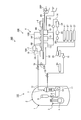
- FIG. 1 is a schematic configuration diagram illustrating an example of a nuclear power plant according to the first embodiment.
- FIG. 2 is a diagram schematically illustrating an example of the piping system and the identification system of the nuclear power plant according to the first embodiment.
- FIG. 3 is a diagram schematically illustrating an example of the gas supply device according to the first embodiment.
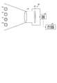
- FIG. 4 is a diagram schematically illustrating an example of a pipe temperature detection device according to the first embodiment.
- FIG. 5 is a functional block diagram illustrating an example of a gas temperature adjusting device of the identification system according to the first embodiment.
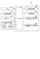
- FIG. 6 is a functional block diagram illustrating an example of a pipe temperature detection device of the identification system according to the first embodiment.
- FIG. 1 is a schematic configuration diagram illustrating an example of a nuclear power plant according to the first embodiment.
- FIG. 2 is a diagram schematically illustrating an example of the piping system and the identification system of the nuclear power plant according to the first embodiment.
- FIG. 3 is a diagram schematically illustrating
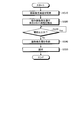
- FIG. 7 is a flowchart illustrating an example of a pipe identification method according to the first embodiment.
- FIG. 8 is a flowchart illustrating an example of a pipe identification method according to the second embodiment.
- FIG. 9 is a functional block diagram illustrating an example of a gas supply device of the identification system according to the third embodiment.
- FIG. 10 is a diagram schematically illustrating an example of an identification system according to the fourth embodiment.
- FIG. 11 is a diagram illustrating an example of an identification system according to the fifth embodiment.
- FIG. 12 is a flowchart illustrating an example of a pipe identification method according to the fifth embodiment.
- FIG. 13 is a diagram schematically illustrating an example of an identification system according to the sixth embodiment.
- FIG. 14 is a diagram schematically illustrating an example of a vibration generator according to the sixth embodiment.
- FIG. 15 is a flowchart illustrating an example of a pipe identification method according to the sixth embodiment.
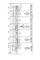
- FIG. 16 is a timing chart showing an operation period of the vibration generator according to the sixth embodiment.
- FIG. 17 is a diagram schematically illustrating an example of an identification system according to the seventh embodiment.
- FIG. 18 is a diagram schematically illustrating an example of a vibration generating device according to the seventh embodiment.
- FIG. 19 is a flowchart illustrating an example of a pipe identification method according to the seventh embodiment.
- FIG. 20 is a schematic diagram for explaining a pipe identification method according to the eighth embodiment.
- FIG. 1 is a schematic configuration diagram illustrating an example of a nuclear power plant 100 according to the present embodiment.
- the nuclear power plant 100 includes a nuclear reactor 1.
- the nuclear reactor 1 is a pressurized water reactor (PWR)
- the nuclear power plant 100 is a nuclear power plant that generates power using nuclear power.
- PWR pressurized water reactor
- the nuclear power plant 100 includes a nuclear reactor system 101 including a nuclear reactor 1 and a turbine system 102 including a steam turbine 5 and a generator 6.
- a nuclear reactor system 101 including a nuclear reactor 1 and a turbine system 102 including a steam turbine 5 and a generator 6.
- primary cooling water circulates.
- turbine system 102 secondary cooling water circulates.
- the reactor system 101 and the turbine system 102 are separated by the steam generator 7.
- the nuclear reactor system 101 includes a primary containment vessel 2, a nuclear reactor pressure vessel 3 stored in the nuclear reactor containment vessel 2, and thermal energy contained in the nuclear reactor pressure vessel 3 and generated by a nuclear reaction.
- a pressurizer 9 for pressurizing water, a pipe 10 connected to each of the reactor pressure vessel 3 and the steam generator 7, and a low-temperature primary cooling water heat-exchanged by the steam generator 7, and a pipe 10 are arranged.
- a primary cooling water pump 11 for supplying the primary cooling water to the reactor pressure vessel 3.
- the turbine system 102 is connected to each of the steam generator 7 and the steam turbine 5, the pipe 12 through which the high-temperature and high-pressure steam generated by the steam generator 7 flows, and the steam turbine 5 operated by the steam from the steam generator 7.
- a generator 6 that is operated by the steam turbine 5, a condenser 13 that cools the steam that has worked in the steam turbine 5 and returns it to water, and a condenser 13 and a steam generator 7, respectively.
- a pipe 14 through which the secondary cooling water from the vessel 13 flows, a secondary cooling water pump 15 that sends the secondary cooling water to the steam generator 7, and a moisture separation heater 17 are provided.
- the primary cooling water When the primary cooling water is pressurized by the pressurizer 9, the boiling point of the primary cooling water rises.
- the high-temperature and high-pressure primary cooling water heated in the reactor pressure vessel 3 and pressurized by the pressurizer 9 is supplied to the steam generator 7 via the pipe 8.
- the steam generator 7 performs heat exchange between the primary cooling water and the secondary cooling water. By the heat exchange between the primary cooling water and the secondary cooling water, steam of the secondary cooling water is generated in the steam generator 7.
- the steam of the secondary cooling water generated by the steam generator 7 is supplied to the steam turbine 5 through the pipe 12 provided with the isolation valve 16.
- the steam turbine 5 includes a high-pressure turbine 5A and a low-pressure turbine 5B, and is driven by steam from the steam generator 7.
- the moisture separator / heater 17 is connected to the high-pressure turbine 5A via the reheat pipe 18A, and is connected to the low-pressure turbine 5B via the reheat pipe 18B.
- the high pressure turbine 5 ⁇ / b> A is driven by the steam supplied from the steam generator 7 through the pipe 12.
- the steam that has worked in the high-pressure turbine 5A is supplied to the moisture separation heater 17 through the reheat pipe 18A. Further, at least a part of the steam from the steam generator 7 is supplied to the moisture separation heater 17 via the branch pipe 19.
- the low-pressure turbine 5B is operated by steam supplied from the moisture separator / heater 17 via the reheat pipe 18B.
- the generator 6 is connected to the steam turbine 5.
- the generator 6 is driven by the steam turbine 5 to generate power.
- the condenser 13 cools the steam worked by the steam turbine 5 and returns it to water.
- An intake pipe 20 for taking in seawater and a drain pipe 21 for discharging seawater are connected to the condenser 13. Seawater is supplied to the condenser 13 through the intake pipe 20 by the operation of the circulating water pump 20P.
- the pipe 12 and the condenser 13 are connected via a bypass pipe 22 provided with a bypass valve 22B.
- a condensate pump 23, a ground condenser 24, a condensate demineralizer 25, a condensate booster pump 26, and a low-pressure feed water heater 27 are disposed in the pipe 14.
- a deaerator 28 is connected to the pipe 14. Further, the pipe 14 is provided with a high-pressure feed water heater 29 and a feed water control valve 30.
- FIG. 2 is a diagram schematically illustrating an example of the piping system PS and the identification system 40A of the nuclear power plant 100 according to the present embodiment.
- the building of the nuclear power plant 100 has a plurality of indoor spaces A, B, C, D, E, F, and G partitioned by walls W.
- walls W are provided at intervals of 1 [m] to 10 [m].
- the building of the nuclear power plant 100 is provided with a plurality of indoor spaces by walls W.
- the indoor spaces A, B, C, D, E, F, and G are schematically shown indoor spaces, and a large number of indoor spaces are actually provided.
- the piping system PS has a plurality of pipings Pa, Pb, Pc, and Pd.
- the plurality of pipes Pa, Pb, Pc, Pd are arranged in the indoor space of the nuclear power plant 100.
- the pipes Pa, Pb, Pc, and Pd are pipes schematically shown, and a large number of pipes are actually provided.
- the plurality of pipes Pa, Pb, Pc, and Pd are disposed over the plurality of indoor spaces A, B, C, D, E, F, and G, respectively.
- the pipes Pa, Pb, Pc, and Pd are arranged so as to penetrate the wall W.
- the dismantling work of the piping system PS is performed.
- a situation occurs in which one of a plurality of pipes is dismantled and other pipes are not dismantled. That is, in the decommissioning process, there are pipes that should be dismantled and pipes that should not be dismantled.
- the pipe Pc is disassembled and the pipes Pa, Pb, and Pd are not disassembled.
- the identification system 40A identifies the piping Pc that should be disassembled and the piping Pa, Pb, and Pd that should not be disassembled.
- the pipe Pc to be disassembled among the plurality of pipes Pa, Pb, Pc, Pd arranged in the indoor space is appropriately referred to as a specific pipe Pc.
- the identification system 40A includes a gas supply device 50 that supplies a gas whose temperature is adjusted to a specific pipe Pc, and pipe temperature detection that detects the temperatures of a plurality of pipes Pa, Pb, Pc, and Pd.
- the apparatus 60 and the indoor temperature detection apparatus 70 which detects the temperature of indoor space are provided.
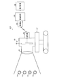
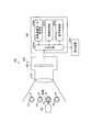
- FIG. 3 is a diagram schematically illustrating an example of the gas supply device 50 according to the present embodiment.
- the gas supply device 50 is disposed in the indoor space A.
- the gas supply device 50 includes a housing 51, a fan 52 that takes the gas in the indoor space A into the housing 51, a gas temperature adjuster 53 that is disposed inside the housing 51 and adjusts the temperature of the gas, and a gas temperature adjuster.
- a nozzle 54 having a supply port 54M for supplying the gas adjusted in temperature to the specific pipe Pc, and a control device 55 for controlling the fan 52 and the gas temperature regulator 53.
- the gas in the indoor space A is air.
- the fan 52 can rotate inside the housing 51. When the fan 52 is activated, the gas in the indoor space A flows into the housing 51.
- the gas temperature adjuster 53 adjusts the temperature of the gas in the indoor space A taken into the housing 51 by the fan 52.
- the gas temperature adjuster 52 has a heater including a heating wire and can heat the gas.
- the gas whose temperature has been adjusted by the gas temperature adjuster 53 is supplied to the flow path of the specific pipe Pc via the supply port 54M provided at the tip of the nozzle 54.
- An opening K is provided in a part of the specific pipe Pc.
- the supply port 54M is arranged in the flow path of the specific pipe Pc.
- the fan 52 and the gas temperature regulator 53 are operated, whereby the heated gas is supplied to the flow path of the specific pipe Pc.
- the gas supply device 50 supplies the gas adjusted to a temperature different from the temperature of the indoor space to the specific pipe Pc.
- the control device 55 includes a computer unit such as a microprocessor, and controls the fan 52 and the gas temperature regulator 53.
- the control device 55 controls the gas temperature regulator 53 so that the difference between the temperature of the gas supplied from the supply port 54M to the specific pipe Pc and the temperature of the indoor space is equal to or greater than a specified value.
- the specified value of the difference between the temperature of the gas supplied to the specific pipe Pc and the temperature of the indoor space is, for example, 10 [° C.].
- the control device 55 controls the gas temperature regulator 53 so that the temperature of the gas supplied from the supply port 54M to the specific pipe Pc is at least 10 [° C.] higher than the temperature of the indoor space.
- the nozzle 54 is provided with a temperature sensor 56 that detects the temperature of the gas supplied from the supply port 54M.
- the control device 55 controls the gas temperature regulator 53 based on the detection value of the temperature sensor 56.
- control device 55 can adjust the amount of gas supplied per unit time supplied from the supply port 54 to the specific pipe Pc by controlling the rotational speed of the fan 52 per unit time.
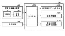
- FIG. 4 is a diagram schematically illustrating an example of the pipe temperature detection device 60 according to the present embodiment.
- the pipe temperature detection device 60 can simultaneously detect the temperatures of the plurality of pipes Pa, Pb, Pc, and Pd in a non-contact manner.
- the pipe temperature detection device 60 includes a thermography.
- the pipe temperature detection device 60 may include an infrared camera.
- the pipe temperature detection device 60 includes an optical system 61 having a visual field area in which a plurality of pipes Pa, Pb, Pc, and Pd including the specific pipe Pc are arranged, and pipes Pa, Pb, Pc, and Pd through the optical system 61. And a detecting element 62 for detecting infrared rays.
- the pipe temperature detection device 60 includes a control device 63 including a computer unit such as a microprocessor, and an output device 64 that outputs pipe temperature data of a plurality of pipes Pa, Pb, Pc, and Pd acquired by the pipe temperature detection device 60. And have.
- the output device 64 is a display device 64 that displays pipe temperature data as image data.
- the display device 64 includes a flat panel display such as a liquid crystal display or an organic EL display.
- the gas supply device 50 includes an indoor space B from a portion Ba of the specific pipe Pc disposed in the indoor space A among the plurality of indoor spaces A, B, C, D, E, F, and G. , C, D, E, and F so that the gas flows through the specific piping Pc portion Bg disposed in the indoor space G through the specific piping Pc portions Bb, Bc, Bd, Be, and Bf.
- the gas is supplied to the specific pipe Pc.
- the gas supplied up to the portion Bg of the specific pipe Pc is released into the atmosphere, for example. Note that the gas supplied up to the portion Bg of the specific pipe Pc may be recovered by a gas recovery device (not shown).
- the indoor temperature detection device 70 detects the temperature of the indoor space G different from the indoor space A in which the gas supply device 50 is disposed.
- the indoor space G is a space on the downstream side of the gas from the indoor space A, and is a space where the gas used for pipe identification is released or collected.
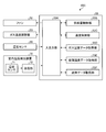
- FIG. 5 is a functional block diagram showing an example of the gas temperature adjusting device 50 of the identification system 40A according to the present embodiment.
- the control device 55 of the gas temperature adjusting device 50 outputs a control signal to the input / output unit 55A and the fan 52, and supplies gas to the specific pipe Pc from the supply port 54M.
- a supply amount control unit 55B that controls the supply amount
- a temperature control unit 55C that outputs a control signal to the gas temperature regulator 53 and controls the temperature of the gas supplied from the supply port 54M to the specific pipe Pc
- a temperature sensor 56 A gas temperature data acquisition unit 55D for acquiring gas temperature data indicating the temperature of the gas supplied to the specific pipe Pc from the supply port 54M, and a detection signal of the indoor temperature detection device 70 to acquire the detection signal
- a space temperature data acquisition unit 55E that acquires space temperature data indicating the temperature of the space G.
- the indoor temperature detection device 70 transmits a temperature sensor 71 that detects the temperature of the indoor space G, and space temperature data that indicates the temperature of the indoor space G detected by the temperature sensor 71 to the control device 55 of the gas supply device 50. Part 72.
- the transmission unit 72 may transmit the space temperature data to the control device 55 by wire, or may transmit to the control device 55 wirelessly.
- FIG. 6 is a functional block diagram showing an example of the pipe temperature detection device 60 of the identification system 40A according to the present embodiment.
- the control device 63 of the pipe temperature detection device 60 acquires a detection signal from the input / output unit 63A and the detection element 62, and each of a plurality of pipes Pa, Pb, Pc, Pd including the specific pipe Pc.
- the pipe temperature data acquisition unit 63B that acquires the pipe temperature data indicating the temperature of the pipe
- the image processing unit 63C that performs image processing on the pipe temperature data acquired by the pipe temperature data acquisition unit 63B, and the pipe temperature data acquisition unit 63B.
- a display control unit 63D for causing the display device 64 to display the pipe temperature data.
- the display control unit 63D generates display data to be displayed on the display device 64 from the pipe temperature data image-processed by the image processing unit 63C, and outputs the display data to the display device 64.
- the display control unit 63D functions as an output control unit that outputs the pipe temperature data acquired by the pipe temperature data acquisition unit 63B.
- the display device 64 displays display data generated based on the pipe temperature data.
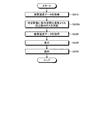
- FIG. 7 is a flowchart illustrating an example of a pipe identification method according to the present embodiment.
- the space temperature data acquisition unit 55E of the gas supply device 50 acquires the space temperature data of the indoor space G from the indoor temperature detection device 70 (step SA10).
- the temperature control unit 55C of the gas supply device 50 controls the gas temperature adjuster 53 so that the temperature of the gas supplied to the specific pipe Pc and the temperature of the indoor space G are different based on the space temperature data.
- the gas temperature regulator 53 supplies the specific pipe Pc with the temperature of the gas supplied to the specific pipe Pc and the temperature of the indoor space G based on the space temperature data acquired by the space temperature data acquisition unit 55E. Adjust the gas temperature.
- the gas supply device 50 supplies the gas adjusted to a temperature different from the temperature of the indoor space G to the specific pipe Pc.
- the gas supply device 50 supplies a gas having a temperature higher than that of the indoor space G to the specific pipe Pc (step SA20).
- the pipe temperature detection device 60 detects the temperature of each of the plurality of pipes Pa, Pb, Pc, Pd.
- the pipe temperature data acquisition unit 63B acquires pipe temperature data from the pipe temperature detection device 60 (step SA30).
- the image processing unit 63C performs image processing on the pipe temperature data.
- the display control unit 63D generates display data to be displayed on the display device 64 based on the pipe temperature data, and outputs the display data to the display device 64.
- the display device 64 displays pipe temperature data indicating the temperatures of the plurality of pipes Pa, Pb, Pc, and Pd (step SA40).
- the high-temperature gas supplied from the gas supply device 50 flows through the specific pipe Pc.
- the surface temperature of the specific pipe Pc is higher than the temperature of the indoor space.
- no gas is supplied from the gas supply device 50 to the other pipes Pa, Pb, and Pd. Therefore, the surface temperatures of the pipes Pa, Pb, and Pd are substantially equal to the temperature of the indoor space.
- a gas having a temperature higher than a specified value than the temperature of the indoor space flows through the specific pipe Pc. Therefore, the difference between the surface temperature of the specific pipe Pc and the surface temperature of the pipes Pa, Pb, and Pd is not less than a specified value (10 [° C.] or more).
- the pipe temperature detection device 60 includes a thermography, and the display device 64 displays the specific pipe Pc and the other pipes Pa, Pb, and Pd in different forms.
- the display device 64 displays the specific pipe Pc in red, for example, and displays the other pipes Pa, Pb, Pd in blue, for example.
- the worker can identify the specific pipe Pc and the other pipes Pa, Pb, and Pd based on the pipe temperature data displayed on the display device 64 (step SA50). By identifying the specific pipe Pc, the worker can perform the disassembly work of the specific pipe Pc.
- the pipe temperature data indicating the temperature of each of the plurality of pipes Pa, Pb, Pc, and Pd is acquired, and the acquired pipe temperature data is displayed on the display device 64.
- the specific pipe Pc and the other pipes Pa, Pb, and Pd can be distinguished from each other without much effort. Further, the identification work of the specific pipe Pc can be performed in a short period with good workability.
- the method of identifying a pipe by flowing a gas through the pipe can omit various processes such as a purification process and a monitoring process as compared with a method of flowing water. Therefore, the cost of decommissioning can be reduced.
- the pipe since the pipe is identified by flowing a gas through the pipe, the pipe can be disassembled immediately after the pipe identification work is completed. Therefore, the period of the decommissioning process can be shortened.
- the method of flowing high temperature gas to piping can suppress the risk of a burn of an operator compared with the method of flowing high temperature water.
- the gas supply device 50 takes the gas in the indoor space A into the housing 51, adjusts the temperature of the taken-in gas, and supplies it to the specific pipe Pc. Therefore, the gas in the indoor space A can be effectively used without preparing complicated equipment.
- the pipes Pa, Pb, Pc, and Pd are arranged over a plurality of indoor spaces A, B, C, D, E, F, and G of the nuclear power plant 100.
- the worker in the indoor space B, the worker in the indoor space D, and the worker in the indoor space F are simultaneously specified pipe. It is preferable that the Pc dismantling operation can be performed.
- the gas supply device 50 includes a portion Bb of the specific pipe Pc disposed in the indoor spaces B, C, D, E, and F from a portion Ba of the specific pipe Pc disposed in the indoor space A.
- the gas is supplied to the specific pipe Pc so that the gas flows through the portion Bg of the specific pipe Pc arranged in the indoor space G through Bc, Bd, Be, Bf. Therefore, the worker in the indoor space B, the worker in the indoor space D, and the worker in the indoor space F can simultaneously identify the specific pipe Pc and the other pipes Pa, Pb, and Pd. Therefore, the disassembly work of the specific pipe Pc can be performed simultaneously in the plurality of indoor spaces B, D, and F.
- the temperature of the indoor space is detected by the indoor temperature detection device 70, and the gas supply device 50 acquires the space temperature data indicating the temperature of the indoor space and supplies the specific pipe Pc with the gas. Adjust the temperature. Therefore, the gas supply device 50 can set the difference between the temperature of the specific pipe Pc and the temperatures of the other pipes Pa, Pb, and Pd to a specified value or more.
- the gas is supplied from the gas supply device 50 to the specific pipe Pc in the indoor space A, the temperature of the indoor space G downstream of the indoor space A is detected by the indoor temperature detection device 70, and the gas
- the supply device 50 acquires space temperature data indicating the temperature of the indoor space G, and adjusts the temperature of the gas supplied to the specific pipe Pc.
- the temperature of the gas supplied to the specific pipe Pc is adjusted based on the temperature of the indoor space G that is different from the indoor space A in which the gas supply device 50 is arranged.
- the difference with the temperature of other piping Pa, Pb, Pd can be made more than a specified value.
- the specific pipe Pc is specified in order to insert the nozzle 54 of the gas supply device 50 into the opening K of the specific pipe Pc.
- the indoor temperature detection device 70 detects the temperature of at least one of the indoor spaces B, C, D, E, and F, and the gas supply device 50 supplies the gas supplied to the specific pipe Pc based on the temperature of the indoor space. You may adjust the temperature.
- the gas supply device 50 may adjust the temperature of the gas supplied to the specific pipe Pc based on the temperature of the indoor space A.
- the pipe temperature data of the pipes Pa, Pb, Pc, and Pd is acquired by the pipe temperature detection device 60 including a thermography having the optical system 61 and the detection element 62. Therefore, the pipe temperature data of the pipes Pa, Pb, Pc, and Pd can be efficiently acquired at the same time.
- a temperature sensor 56 that detects the temperature of the gas supplied from the gas supply device 50 to the specific pipe Pc is provided, and the gas supply device 50 is specified based on the detection value of the temperature sensor 56. The temperature of the gas supplied to the pipe Pc is adjusted. For this reason, the gas supply device 50 can accurately supply a gas having a temperature difference between the temperature of the indoor space and a specified value or more.
- a temperature sensor that detects the temperature of the portion Bg of the specific pipe Pc in the indoor space G is provided, and is supplied from the gas supply device 50 to the specific pipe Pc based on the detection value of the temperature sensor.
- the temperature of the gas to be adjusted may be adjusted.
- the portions Bb, Bc, Bd, Be, Bf of the specific pipe Pc are used. There is a possibility that the difference between the temperature of the gas and the temperature of the indoor space G becomes small in the portion Bg of the indoor space G.
- the temperature of the part Bg of the specific pipe Pc is detected by the temperature sensor, and the control device 55 is configured so that the difference between the temperature of the part Bg of the specific pipe Pc and the temperature of the indoor space G is equal to or greater than a specified value.
- at least one of the gas temperature regulator 53 may be controlled.
- the control device 55 sets the temperature of the gas supplied from the supply port 54M to the specific pipe Pc so that the difference between the temperature of the part Bg of the specific pipe Pc and the temperature of the indoor space G is 10 [°] or more. It may be increased, or the amount of gas supplied per unit time supplied from the supply port 54M to the specific pipe Pc may be increased.
- FIG. 8 is a flowchart showing an example of a pipe identification method according to this embodiment.
- the space temperature data acquisition unit 55E of the gas supply device 50 acquires the space temperature data of the indoor space G from the indoor temperature detection device 70 (step SA10). Based on the space temperature data, the temperature control unit 55C of the gas supply device 50 controls the gas temperature regulator 53 so that the temperature of the gas supplied to the specific pipe Pc and the temperature of the indoor space G are equal to or higher than a specified value.
- the gas temperature regulator 53 includes a chiller device that can cool the supplied gas.
- the gas supply device 50 supplies a gas having a lower temperature than the indoor space G to the specific pipe Pc (step SA20b).
- the pipe temperature detection device 60 detects the temperature of each of the plurality of pipes Pa, Pb, Pc, Pd.
- the pipe temperature data acquisition unit 63B acquires pipe temperature data from the pipe temperature detection device 60 (step SA30).
- the display control unit 63D generates display data to be displayed on the display device 64 based on the pipe temperature data, and outputs the display data to the display device 64.
- the display device 64 displays pipe temperature data indicating the temperatures of the plurality of pipes Pa, Pb, Pc, and Pd (step SA40).
- the operator can identify the specific pipe Pc and the other pipes Pa, Pb, and Pd based on the pipe temperature data displayed on the display device 64 (step SA50). Thereby, the dismantling operation
- the gas supply device 50 may supply a gas having a temperature lower than the temperature of the indoor space G to the specific pipe Pc.
- the gas can flow smoothly in the specific pipe Pc by using a low-temperature gas. In addition, there is no risk of operator burns.
- FIG. 9 is a functional block diagram showing an example of the gas supply device 50 of the identification system 40C according to the present embodiment.
- the control device 55 includes a fluid data acquisition unit 55F that acquires fluid data that has been distributed to the specific pipe Pc during the operation period before the dismantling operation.
- the fluid data may be input to the fluid data acquisition unit 55F via an input device such as a keyboard or a touch panel.
- the fluid data may be stored in a storage device such as a storage, and the fluid data acquisition unit 55F may acquire the fluid data from the storage device.
- the temperature control unit 55C sets the temperature of the gas supplied to the specific pipe Pc at a temperature higher or lower than the temperature of the indoor space G based on the fluid data acquired by the fluid data acquisition unit 55F. Adjust to either one.
- the gas temperature regulator 53 is connected to the specific pipe Pc based on the fluid data acquired by the fluid data acquisition unit 55F.
- the temperature of the supplied gas is adjusted to a temperature lower than the temperature of the indoor space G.
- the gas temperature regulator 53 passes through the specific pipe Pc based on the fluid data acquired by the fluid data acquisition unit 55E.
- the temperature of the supplied gas is adjusted to a temperature higher than the temperature of the indoor space G.
- the gas temperature adjusting device 50 can switch between the supply of the high temperature gas and the supply of the low temperature gas based on the fluid data.
- the gas temperature adjusting device 50 may supply a low temperature gas to the specific pipe Pc. Further, when the dismantling operation is performed in winter and the temperature of the indoor space is low, the gas temperature adjusting device 50 may supply a high-temperature gas to the specific pipe Pc. By doing so, the physical burden on the worker who performs the dismantling work is reduced.
- FIG. 10 is a diagram schematically illustrating an example of the identification system 40D according to the present embodiment.
- the control device 63 and the display device 64 are provided in the pipe temperature detection device 60.
- the control device 63 and the display device 64 are arranged at a remote place of the pipe temperature detection device 60.
- the pipe temperature detection device 60 including the optical system 61 and the detection element 62 is mounted on a mobile robot 67.
- the pipe temperature detection device 60 and the mobile robot 67 are controlled by remote operation.
- the pipe temperature data acquired by the pipe temperature detection device 60 is transmitted to the control device 63 by wireless communication.
- the pipe temperature detection device 60 includes a transmitter 65 capable of wirelessly transmitting pipe temperature data.
- the control device 63 has a receiver 66 that can wirelessly receive pipe temperature data.
- the control device 63 causes the display device 64 to display the received pipe temperature data.
- the operator can identify the specific pipe Pc and the other pipes Pa, Pb, and Pd at a remote place in the indoor space.
- the output device 64 is the display device 64.
- the output device 64 may be a printing device that prints out pipe temperature data.
- FIG. 11 is a diagram illustrating an example of the identification system 40E according to the present embodiment.
- the identification system 40E is adjusted to a temperature lower than the temperature of the indoor space in the specific pipe Pc so that the surface of the specific pipe Pc of the plurality of pipes Pa, Pb, Pc, Pd arranged in the indoor space is condensed.
- the refrigerant may be a gas or a liquid.
- the surfaces of the other pipes Pa, Pb, and Pd to which no refrigerant is supplied do not condense. Therefore, the worker can identify the specific pipe Pc and the other pipes Pa, Pb, and Pd through vision. Since the operator can identify the specific pipe Pc by visual observation, the identification system 40E can be simplified.
- a refrigerant eliminates the risk of operator burns. Moreover, it is applicable also to the specific piping Pc with low heat resistance.
- the evaluation member 32 whose appearance changes when it gets wet may be arranged on the surface of each of the plurality of pipes Pa, Pb, Pc, Pd including the specific pipe Pc.
- the evaluation member 32 may be a test paper whose color changes due to contact with a liquid, for example.
- the evaluation system 40E may include an imaging device 60E that can acquire image data of the pipes Pa, Pb, Pc, and Pd.
- an identification method using the imaging device 60E will be described.
- the imaging device 60E includes an optical system 61E having a visual field area in which a plurality of pipes Pa, Pb, Pc, and Pd including the specific pipe Pc are arranged, and the pipes Pa and Pb via the optical system 61E. , Pc, and Pd. Image data of the pipes Pa, Pb, Pc, and Pd is acquired by the imaging device 60E.
- the control device 63E of the imaging device 60E performs image processing on the input / output unit 63Ae, the piping image data acquisition unit 63Be that acquires image data acquired by the imaging device 60E, and the image data acquired by the piping image data acquisition unit 63Be.
- An image processing unit 63Ce that generates the display data to be displayed on the display device 64E based on the image data acquired by the pipe image data acquisition unit 63Be, and outputs the display data to the display device 64E. Have.
- FIG. 12 is a flowchart showing an example of a pipe identification method according to this embodiment.
- the refrigerant supply device 50E supplies the refrigerant to the specific pipe Pc (Step SE10).
- the imaging device 60E detects image data of each of the plurality of pipes Pa, Pb, Pc, Pd.
- the pipe image data acquisition unit 63Be acquires image data from the imaging device 60E (step SE20).
- the display control unit 63De generates display data to be displayed on the display device 64E based on the image data of the pipes Pa, Pb, Pc, and Pd, and outputs the display data to the display device 64E.
- the display device 64E displays the image data of each of the plurality of pipes Pa, Pb, Pc, Pd (step SE30).
- the operator can identify the specific pipe Pc and the other pipes Pa, Pb, Pd based on the image data displayed on the display device 64E (step SE40). Thereby, the dismantling operation
- the specific pipe Pc is a pipe that should be disassembled, and the other pipes Pa, Pb, and Pd are pipes that should not be disassembled.
- the specific pipe Pc is a pipe that should not be disassembled, and other pipes Pa, Pb, and Pd may be pipes that should be disassembled.
- FIG. 13 is a diagram schematically illustrating an example of an identification system 40F according to the present embodiment.
- the plurality of pipes Pa, Pb, Pc, and Pd are respectively disposed across the plurality of indoor spaces A, B, C, D, E, F, and G in which the nuclear power plant 100 is partitioned.
- the specific pipe Pc is a pipe that should not be disassembled
- the other pipes Pa, Pb, and Pd are pipes that should be disassembled.
- the identification system 40F includes a plurality of vibration generators 80 arranged at intervals on the specific pipe Pc.
- the vibration generator 80 includes a vibration generator 80A arranged in the indoor space A, a vibration generator 80B arranged in the indoor space D, and a vibration generator 80C arranged in the indoor space F. ,including.
- the identification system 40F continues to vibrate the specific pipe Pc or the fluid of the specific pipe Pc using the vibration generating device 80 during the disassembly work of the pipes Pa, Pb, and Pd.
- the operator can identify the piping Pa, Pb, Pd to be disassembled and the specific piping Pc that should not be disassembled in the dismantling operation of the piping Pa, Pb, Pd. Therefore, it is possible to prevent the specific pipe Pc from being disassembled by mistake.
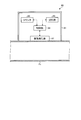
- FIG. 14 is a diagram schematically illustrating an example of the vibration generator 80 according to the present embodiment.
- the vibration generator 80 includes a housing 81, a vibration generator 82, a counter 83, a control unit 84 that controls the vibration generator 82, and a storage unit 85.
- the vibration generator 82, the counter 83, the control unit 84, and the storage unit 85 are disposed inside the housing 81.
- the vibration generator 82 is disposed so as to contact the surface of the specific pipe Pc.
- the vibration generator 82 vibrates the specific pipe Pc and vibrates the fluid existing in the flow path of the specific pipe Pc.
- the counter 83 counts the count value at a constant cycle.
- the counter 83 includes a clock that counts time at a constant period.
- the count value of the counter 83 is output to the control unit 84.
- the control unit 84 includes a computer unit such as a microprocessor, and controls the vibration generator 82 by outputting a control signal to the vibration generator 82.
- the storage unit 85 includes a memory such as a ROM (Read Only Memory) or a RAM (Random Access Memory), and a vibration generator 82 (an external vibration generator) of another vibration generator 80 arranged in the specific pipe Pc.
- the vibration condition data is stored.
- the storage unit 85 of the vibration generator 80C stores vibration condition data of the vibration generators 82 of the other vibration generators 80A and 80B.
- the counters 83 of the plurality of vibration generators 80A, 80B, 80C operate in synchronization. That is, the counter 83 of the vibration generator 80A, the counter 83 of the vibration generator 80B, and the counter 83 of the vibration generator 80C count the count value (time) at the same cycle and timing.
- each of the plurality of vibration generators 80A, 80B, 80C operates the vibration generator 82 for a predetermined operation period.
- the operation period of the vibration generator 82 is determined based on the count value of the counter 83.
- Each of the plurality of vibration generators 80A, 80B, and 80C controls the vibration generator 82 based on the count value of the counter 83 so that the operation periods of the vibration generators 82 do not overlap each other.
- the counter 83 of the vibration generator 80C operates in synchronization with the counters 83 of the other vibration generators 80A and 80B. Based on the count value of the counter 83 of the vibration generator 80C, the control unit 84 of the vibration generator 80C does not overlap the operation period of the vibration generator 82 of the other vibration generators 80A and 80B. The vibration generator 82 is controlled.
- the storage unit 85 of the vibration generator 80C stores vibration condition data including the period and timing of the count value of the counter 83 of the vibration generators 80A and 80B and the operation period of the vibration generator 82.
- the control unit 84 of the vibration generating device 80C can select another vibration generating device based on the count value of the counter 83 of the vibration generating device 80C and the vibration condition data stored in the storage unit 85 of the vibration generating device 80C.
- the vibration generator 82 of the vibration generator 80C can be controlled so as not to overlap with the operation period of the vibration generators 82A and 80B. The same applies to the vibration generators 80A and 80B.
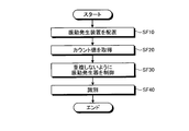
- FIG. 15 is a flowchart illustrating an example of a pipe identification method according to the present embodiment.
- a plurality of vibration generators 80A, 80B, and 80C are arranged at intervals to the specific pipe Pc that should not be disassembled (step SF10).
- the control unit 84 of the vibration generating device 80A acquires the count value of the counter 83 of the vibration generating device 80A.
- the control unit 84 of the vibration generator 80B acquires the count value of the counter 83 of the vibration generator 80B
- the control unit 84 of the vibration generator 80C acquires the count value of the counter 83 of the vibration generator 80C.
- the control unit 84 of the vibration generator 80A includes the count value of the counter 83 of the vibration generator 80A and the vibration generators 82B and 82C of the other vibration generators 80B and 80C stored in the storage unit 85 of the vibration generator 80A. Based on the vibration condition data (see FIG. 16), the vibration generator 82A of the vibration generator 80A (FIG. 16) is used so as not to overlap with the operation periods of the vibration generators 82B and 82C of the other vibration generators 80B and 80C. Control).
- the control unit 84 of the vibration generator 80B includes the count value of the counter 83 of the vibration generator 80B and the vibration generators of the other vibration generators 80A and 80C stored in the storage unit 85 of the vibration generator 80B. Based on the vibration condition data of 82A and 82C, the vibration generator 82B of the vibration generator 80B is controlled so as not to overlap with the operation period of the vibration generators 82A and 82C of the other vibration generators 80A and 80C.
- the control unit 84 of the vibration generator 80C includes the count value of the counter 83 of the vibration generator 80C and the vibration generators of the other vibration generators 80AA and 80B stored in the storage unit 85 of the vibration generator 80C. Based on the vibration condition data of 82A and 82B, the vibration generator 82C of the vibration generator 80C is controlled so as not to overlap with the operation period of the vibration generators 82A and 82B of the other vibration generators 80A and 80B (step) SF30).
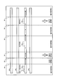
- FIG. 16 is a timing chart showing operation periods of the vibration generators 82A, 82B, and 82C of the vibration generators 80A, 80B, and 80C according to the present embodiment.
- each of the plurality of vibration generators 80A, 80B, 80C has vibration generators 82A, 82A, 80C, 80A, 82B, 80C so that their operation periods (vibration generation periods) do not overlap each other.
- 82B and 82C are controlled.
- the vibration generated by the vibration generator 82A and the vibration generated by at least one of the vibration generators 82B and 82C cancel each other, and the vibration can be attenuated. There is sex.
- the operator can perform the pipe Pa, , Pb, Pd and the specific piping Pc can be identified (step SF40). Thereby, it is suppressed that specific piping Pc will be demolished accidentally.
- FIG. 17 is a diagram schematically illustrating an example of an identification system 40G according to the present embodiment.
- the plurality of pipes Pa, Pb, Pc, and Pd are respectively disposed across the plurality of indoor spaces A, B, C, D, E, F, and G in which the nuclear power plant 100 is partitioned.
- the specific pipe Pc is a pipe that should not be disassembled, and the other pipes Pa, Pb, and Pd are pipes that should be disassembled.
- the identification system 40G includes a plurality of vibration generators 90 that are arranged at intervals in the specific pipe Pc.
- the vibration generator 90 includes a vibration generator 90A disposed in the indoor space A, a vibration generator 90B disposed in the indoor space D, and a vibration generator 90C disposed in the indoor space F. ,including.
- FIG. 18 is a diagram schematically illustrating an example of the vibration generator 90 according to the present embodiment.
- the vibration generator 90 includes a housing 91, a vibration generator 92, a vibration detector 93, a control unit 94 for controlling the vibration generator 92, and a detection value of the vibration detector 93 as a threshold value. And a determination unit 95 that determines whether or not the above is true.
- the vibration generator 92, the vibration detector 93, the control unit 94, and the determination unit 95 are disposed inside the housing 91.
- the vibration generator 92 is disposed so as to contact the surface of the specific pipe Pc.
- the vibration generator 92 applies vibration to the specific pipe Pc to vibrate the fluid existing in the flow path of the specific pipe Pc.
- the vibration detector 93 is disposed so as to contact the surface of the specific pipe Pc.
- the vibration detector 93 detects vibration generated by a vibration generator 92 (external vibration generator) of another vibration generator 90 disposed in the specific pipe Pc.
- the vibration detector 93 of the vibration generator 90C detects the vibration generated by the vibration generator 92 of the other vibration generators 90A and 90B.
- the control unit 94 includes a computer unit such as a microprocessor, and outputs a control signal to the vibration generator 92 to control the vibration generator 92.
- the controller 94 does not operate the vibration generator 92 during the vibration detection period of the vibration detector 93.
- the determination unit 95 includes a computer unit such as a microprocessor, and determines whether or not the detection value of the vibration detector 93 is equal to or greater than a threshold value.
- the vibration generator 92 of the vibration generator 90A when the vibration generator 92 of the vibration generator 90A is activated, the vibration generated by the vibration generator 92 propagates through the specific pipe Pc or the fluid in the flow path of the specific pipe Pc, and the vibration detector 93 of the vibration generator 90B. To reach.
- the vibration detector 93 of the vibration generator 90B detects the vibration generated by the vibration generator 92 of the other vibration generator 90A. In the vibration detection period in which the vibration generated by the vibration generator 92 of the vibration generator 90A is detected by the vibration detector 93 of the vibration generator 90B, the vibration generator 92 of the vibration generator 90B is not activated.
- the determination unit 95 of the vibration generator 90B determines whether or not the detection value of the vibration detector 93 of the vibration generator 90B is equal to or greater than a predetermined threshold value.
- the control unit 94 of the vibration generation device 90B causes the vibration generator 92 of the vibration generation device 90B. Is activated. Thereby, even if the vibration generated by the vibration generator 90A in the indoor space A is attenuated before reaching the specific pipe Pc in the indoor space D, the vibration generator 90B generates the vibration.
- the vibration generator 90C detects the vibration generated by the vibration generator 92 of the vibration generator 90B.
- the control unit 94 of the vibration generation device 90C controls the vibration generator 92 of the vibration generation device 90C. Is activated. Thereby, vibration propagates reliably to the downstream side (the indoor space G side).
- FIG. 19 is a flowchart illustrating an example of a pipe identification method according to the present embodiment.
- the plurality of vibration generators 90A, 90B, and 90C are arranged at intervals to the specific pipe Pc that should not be disassembled (step SG10).
- the control unit 94 of the vibration generator 90A operates the vibration generator 92 of the vibration generator 90A. Thereby, the fluid of the specific piping Pc of the indoor space A or the flow path of the specific piping Pc vibrates. The vibration generated in the specific pipe Pc in the indoor space A propagates to the specific pipe Pc in the indoor space D.
- the vibration detector 93 of the vibration generator 90B arranged in the indoor space D detects the vibration generated by the vibration generator 92 of the vibration generator 90A (step SG20).
- the determination unit 95 of the vibration generator 90B determines whether or not the detection value of the vibration detector 93 of the vibration generator 90B is equal to or greater than a threshold value (step SG30).
- step SG30 when it is determined that the detection value of the vibration detector 93 of the vibration generator 90B is not equal to or greater than the threshold value (step SG30: No), the control unit 94 of the vibration generator 90B controls the vibration generator of the vibration generator 90B. 93 is operated (step SG40).
- the worker in the indoor space D can identify the pipes Pa, Pb, Pd and the specific pipe Pc in the dismantling work of the pipes Pa, Pb, Pd (step SG50). Thereby, it is suppressed that specific piping Pc will be demolished accidentally.
- step SG30 when it is determined that the detection value of the vibration detector 93 of the vibration generator 90B is equal to or greater than the threshold value (step SG30: Yes), the control unit 94 of the vibration generator 90B controls the vibration generator 90B.
- the vibration generator 93 may not be activated.
- vibration generator 90C is the same as the operation of the vibration generator 90B, and thus the description thereof is omitted.
- the vibration detector 93 of the vibration generator 90 disposed on the downstream side detects the vibration generated by the vibration generator 92 of the upstream vibration generator 90.
- the control unit 94 of the vibration generator 90 on the downstream side operates the vibration generator 92. Therefore, even if the vibration generated by the vibration generator 90 on the upstream side is attenuated, the vibration generator 90 on the downstream side generates vibration, so that the vibration can be reliably transmitted to the downstream side of the specific pipe Pc. . Therefore, vibration spreads from one end portion to the other end portion of the specific pipe Pc, and an operator in each indoor space can reliably identify the pipes Pa, Pb, Pd and the specific pipe Pc.
- FIG. 20 is a schematic diagram for explaining a pipe identification method according to the present embodiment.
- the mark 34 is given to the specific pipe Pc among the plurality of pipes Pa, Pb, Pc, Pd arranged in the indoor space.
- the mark 34 is a sheet member (seal) having an adhesive layer that can adhere to the surface of the specific pipe Pc, for example.
- the operator gives a mark 34 to the specific piping Pc based on the design data of the piping system PS.
- the worker gives a mark 34 to the specific piping Pc while referring to a system diagram or piping diagram in which design data of the piping system PS is written.
- the worker who performs the dismantling work can identify the specific pipe Pc and the other pipes Pa, Pb, and Pd based on the mark 34.
- the mark 34 is a mark indicating that the specific pipe Pc is a pipe to be disassembled. As shown in FIG. 20, the mark 34 includes data indicating the dismantling time of the specific pipe Pc.
- a mark 34 including data indicating that the dismantling time has been changed or a mark 34 including data indicating that the order of dismantling has been changed may be given to the pipe.
- the mark 34 may be given to the specific piping Pc to be demolished by the operator before the dismantling work is performed. Thereby, the worker who performs the dismantling operation can identify the piping Pc to be dismantled and the piping Pa, Pb, Pd that should not be dismantling.
- the object to be identified may not be a pipe, and may be an object to identify various members in the dismantling work of incidental facilities of a nuclear power plant.
- the piping is arranged in the indoor space of the nuclear power plant 100. At least a part of the piping may be disposed in an outdoor (outdoor) space.
- the nuclear power plant 100 includes a pressurized water reactor.
- the nuclear power plant 100 may include a boiling water reactor (BWR: Boiling Water Reactor).
- the members are identified in the dismantling work of the incidental equipment in the decommissioning process of the nuclear power plant 100.
- the above-described identification system and identification method can be applied.
- the members of the nuclear power plant 100 not only the members of the nuclear power plant 100 but also the identification system and the identification method described above can be applied to the identification of the members of the chemical plant.
Landscapes
- Engineering & Computer Science (AREA)
- Physics & Mathematics (AREA)
- General Physics & Mathematics (AREA)
- Architecture (AREA)
- Spectroscopy & Molecular Physics (AREA)
- General Engineering & Computer Science (AREA)
- Chemical & Material Sciences (AREA)
- Life Sciences & Earth Sciences (AREA)
- High Energy & Nuclear Physics (AREA)
- Mechanical Engineering (AREA)
- Civil Engineering (AREA)
- Biochemistry (AREA)
- Electrochemistry (AREA)
- Plasma & Fusion (AREA)
- Health & Medical Sciences (AREA)
- Chemical Kinetics & Catalysis (AREA)
- Analytical Chemistry (AREA)
- Structural Engineering (AREA)
- General Health & Medical Sciences (AREA)
- Immunology (AREA)
- Pathology (AREA)
- General Life Sciences & Earth Sciences (AREA)
- Geophysics (AREA)
- Monitoring And Testing Of Nuclear Reactors (AREA)
- Investigating Or Analyzing Materials Using Thermal Means (AREA)
- Radiation Pyrometers (AREA)
Abstract
識別システムは、ガス温度調整器を有し、空間に配置されている複数の配管のうち特定配管に空間の温度とは異なる温度に調整されたガスを供給するガス供給装置と、特定配管を含む複数の配管それぞれの温度を示す配管温度データを取得する配管温度データ取得部と、配管温度データ取得部で取得された配管温度データを出力する出力制御部と、を備える。
Description
本発明は、識別システム、振動発生装置、及び識別方法に関する。
原子力プラントの廃炉工程においては、原子炉の解体作業及び配管のような付帯設備の解体作業が実施される。付帯設備は、原子力プラントの機能及び安全性を確保しつつ徐々に解体される。例えば複数の配管が存在する場合、廃炉工程のある期間においては、ある配管を解体し他の配管を解体しないという状況が発生する。すなわち、廃炉工程においては、解体すべき配管と解体すべきでない配管とが存在することとなる。
一般に、原子力プラントは、壁で区画された複数の室内空間を有する。配管は、それら複数の室内空間に亘って配置される。室内空間に入って配管の解体作業を実施する作業者は、解体すべき配管と解体すべきでない配管とを識別する必要がある。作業者は、例えば原子力プラントの系統図又は配管図を参照しながら、解体すべき配管と解体すべきでない配管とを識別することとなる。
原子力プラントの配管の数は膨大である。そのため、系統図又は配管図を参照しながら作業者が配管を識別する作業は、多大な労力を伴う困難な作業であり、作業時間の長期化をもたらす。
また、例えば、ある室内空間において解体すべき配管が特定されても、別の室内空間において、作業者が視覚等に基づいてその配管を特定することは困難である。そのため、ある室内空間において解体すべき配管が特定されても、別の室内空間においては、作業者は、再度、系統図又は配管図を参照しながら配管を識別する作業を実施する必要がある。
また、系統図又は配管図を参照しながら作業者が配管を識別する作業は、ヒューマンエラーをもたらす可能性が高い。ヒューマンエラーにより、例えば解体すべきでない配管が解体されてしまう可能性がある。
特許文献1には、計装配管に温水を流して計装配管経路を確認する技術が開示されている。
配管に温水を流して配管を識別する方法の場合、その温水に放射性物質又は化学物質が含まれる可能性があるため、使用した温水の浄化処理及びモニタリング処理を実施する必要が生じる。浄化処理及びモニタリング処理にはコストが発生するため、廃炉作業の高コスト化をもたらす。また、配管に温水を流して配管を識別する方法の場合、配管の解体作業は、その配管から温水を除去した後に実施する必要がある。また、温水が漏洩すると、漏洩した温水を回収する作業が発生したり、作業者が火傷を負ったりする可能性がある。また、耐熱性が低いシール部材が配管に設けられている場合、その配管に温水を流すことは困難である。
本発明の態様は、複数の配管又は部材の中から対象となる配管又は部材と他の配管又は部材とを作業性良く識別できる識別システム、振動発生装置、及び識別方法を提供することを目的とする。
本発明の第1の態様は、ガス温度調整器を有し、空間に配置されている複数の配管のうち特定配管に前記空間の温度とは異なる温度に調整されたガスを供給するガス供給装置と、前記特定配管を含む複数の前記配管それぞれの温度を示す配管温度データを取得する配管温度データ取得部と、前記配管温度データ取得部で取得された前記配管温度データを出力する出力制御部と、を備える識別システムを提供する。
本発明の第1の態様において、前記ガス供給装置は、前記ガス温度調整器が配置されるハウジングと、前記空間のガスを前記ハウジングに取り入れるファンと、前記ハウジングに取り入れられ前記ガス温度調整器で温度が調整された前記空間のガスを前記特定配管に供給する供給口を有するノズルと、を有する、ことが好ましい。
本発明の第1の態様において、前記空間は、原子力プラントの区画された複数の室内空間を含み、前記特定配管を含む複数の前記配管はそれぞれ、複数の前記室内空間に亘って配置されてもよい。
本発明の第1の態様において、前記室内空間の温度を示す空間温度データを取得する空間温度データ取得部を備え、前記ガス供給装置は、前記空間温度データ取得部で取得された前記空間温度データに基づいて前記特定配管に供給する前記ガスの温度を調整する、ことが好ましい。
本発明の第1の態様において、前記ガス供給装置は、複数の前記室内空間のうち第1室内空間に配置されている前記特定配管の第1部分から第2室内空間に配置されている前記特定配管の第2部分に前記ガスが流れるように前記特定配管に前記ガスを供給し、前記空間温度データ取得部は、前記第2室内空間の空間温度データを取得し、前記ガス温度調整器は、前記特定配管に供給する前記ガスの温度と前記第2室内空間の温度とが異なるように、前記特定配管に供給する前記ガスの温度を調整する、ことが好ましい。
本発明の第1の態様において、前記配管温度データは、前記特定配管を含む複数の前記配管が配置される視野領域を有する光学系と、前記光学系を介して前記配管からの赤外線を検出する検出素子と、を有する配管温度検出装置によって取得され、前記配管温度データ取得部は、前記配管温度検出装置から前記配管温度データを取得する、ことが好ましい。
本発明の第1の態様において、前記特定配管に流通していた流体データを取得する流体データ取得部を備え、前記ガス温度調整器は、前記流体データ取得部で取得された前記流体データに基づいて、前記特定配管に供給する前記ガスの温度を、前記空間の温度よりも高い温度又は低い温度のいずれか一方に調整する、ことが好ましい。
本発明の第2の態様は、室内空間に配置されている複数の配管のうち特定配管の表面が結露するように、前記特定配管に前記室内空間の温度よりも低い温度に調整された冷媒を供給する冷媒供給装置を備える、識別システムを提供する。
本発明の第2の態様において、濡れることによって外観が変化する評価部材が前記特定配管を含む複数の前記配管それぞれの表面に配置され、前記特定配管を含む複数の前記配管が配置される視野領域を有する光学系と、前記光学系を介して前記配管の光学像を取得する撮像素子と、を有する撮像装置によって前記配管の画像データが取得され、前記画像データを取得する配管画像データ取得部と、前記配管画像データ取得部で取得された前記画像データを出力する出力制御部と、を備えることが好ましい。
本発明の第2の態様において、前記室内空間は、原子力プラントの区画された複数の室内空間を含み、前記特定配管を含む複数の前記配管はそれぞれ、複数の前記室内空間に亘って配置されてもよい。
本発明の第3の態様は、空間に配置されている複数の部材のうち特定部材に間隔をあけて配置された複数の振動発生装置を備え、前記振動発生装置は、振動発生器と、カウンタと、前記振動発生器を制御する制御部と、を有し、第1の振動発生装置の前記カウンタは、他の振動発生装置の前記カウンタと同期して作動し、前記第1の振動発生装置の前記制御部は、前記第1の振動発生装置の前記カウンタのカウント値に基づいて、他の振動発生装置の前記振動発生器の作動期間と重複しないように、前記第1の振動発生装置の前記振動発生器を制御する、識別システムを提供する。
本発明の第4の態様は、空間に配置されている複数の部材のうち特定部材に間隔をあけて配置された複数の振動発生装置を備え、前記振動発生装置は、振動発生器と、振動検出器と、前記振動発生器を制御する制御部と、前記振動検出器の検出値が閾値以上か否かを判定する判定部と、を有し、第1の振動発生装置の前記振動検出器は、他の振動発生装置の振動発生器で発生された振動を検出し、前記判定部において前記検出値が閾値以上でないと判定されたとき、前記第1の振動発生装置の前記制御部は、前記第1の振動発生装置の前記振動発生器を作動させる、識別システムを提供する。
本発明の第3又は第4の態様において、前記空間は、原子力プラントの区画された複数の室内空間を含み、前記特定部材を含む複数の前記部材はそれぞれ、複数の前記室内空間に亘って配置されてもよい。
本発明の第5の態様は、空間に配置されている複数の部材のうち特定部材に配置される振動発生器と、カウンタと、前記振動発生器を制御する制御部と、前記特定部材に配置されている外部振動発生器の振動条件データを記憶する記憶部と、を備え、前記制御部は、前記カウンタのカウント値と前記記憶部に記憶されている前記振動条件データとに基づいて、前記外部振動発生器の作動期間と重複しないように前記振動発生器を制御する、振動発生装置を提供する。
本発明の第6の態様は、空間に配置されている複数の部材のうち特定部材に配置される振動発生器と、前記特定部材に配置されている外部振動発生器で発生された振動を検出する振動検出器と、前記振動発生器を制御する制御部と、前記振動検出器の検出値が閾値以上か否かを判定する判定部と、を有し、前記判定部において前記検出値が閾値以上でないと判定されたとき、前記制御部は、前記振動発生器を作動させる、振動発生装置を提供する。
本発明の第5又は第6の態様において、前記空間は、原子力プラントの区画された複数の室内空間を含み、前記特定部材を含む複数の前記部材はそれぞれ、複数の前記室内空間に亘って配置されてもよい。
本発明の第7の態様は、空間に配置されている複数の配管のうち特定配管に前記空間の温度とは異なる温度に調整されたガスを供給することと、前記特定配管を含む複数の前記配管それぞれの温度を示す配管温度データを取得することと、前記配管温度データに基づいて、前記特定配管と他の配管とを識別することと、を含む識別方法を提供する。
本発明の第8の態様は、室内空間に配置されている複数の配管のうち特定配管の表面が結露するように、前記特定配管に前記室内空間の温度よりも低い温度に調整された冷媒を供給することと、前記結露した前記特定配管の表面に基づいて、前記特定配管と他の配管とを識別することと、を含む識別方法を提供する。
本発明の第9の態様は、空間に配置されている複数の部材のうち特定部材に間隔をあけて複数の振動発生装置を配置することと、複数の前記振動発生装置のそれぞれに設けられている振動発生器の作動期間が重複しないように、複数の前記振動発生装置のそれぞれに設けられているカウンタのカウント値に基づいて、複数の前記振動発生装置それぞれの前記振動発生器を作動させることと、を含む識別方法を提供する。
本発明の第10の態様は、空間に配置されている複数の部材のうち特定部材に間隔をあけて複数の振動発生装置を配置することと、複数の前記振動発生装置のうち第1の振動発生装置の振動検出器で、他の振動発生装置の振動発生器で発生された振動を検出すること、前記振動検出器の検出値が閾値以上か否かを判定することと、前記検出値が閾値以上でないと判定されたとき、第1の前記振動発生装置の振動発生器を作動させることと、を含む識別方法を提供する。
本発明の第11の態様は、配管システムの設計データに基づいて、空間に配置されている複数の部材のうち特定部材にマークを付与することと、前記マークに基づいて、前記特定部材と他の部材とを識別することと、を含む識別方法を提供する。
本発明の第11の態様において、前記マークは、前記特定部材が解体される部材であることを示すマークである、ことが好ましい。
本発明の第11の態様において、前記マークは、前記特定部材の解体時期を示すデータを含む、ことが好ましい。
本発明の態様によれば、複数の配管又は部材の中から対象となる配管又は部材と他の配管又は部材とを作業性良く識別できる識別システム、振動発生装置、及び識別方法が提供される。
以下、本発明に係る実施形態について図面を参照しながら説明するが、本発明はこれに限定されない。以下で説明する各実施形態の要件は、適宜組み合わせることができる。また、一部の構成要素を用いない場合もある。
<第1実施形態>
第1実施形態について説明する。図1は、本実施形態に係る原子力プラント100の一例を示す概略構成図である。原子力プラント100は、原子炉1を備える。本実施形態において、原子炉1は、加圧水型原子炉(PWR:Pressurized Water Reactor)であり、原子力プラント100は、原子力を使って発電する原子力発電プラントである。
第1実施形態について説明する。図1は、本実施形態に係る原子力プラント100の一例を示す概略構成図である。原子力プラント100は、原子炉1を備える。本実施形態において、原子炉1は、加圧水型原子炉(PWR:Pressurized Water Reactor)であり、原子力プラント100は、原子力を使って発電する原子力発電プラントである。
原子力プラント100は、原子炉1を含む原子炉系101と、蒸気タービン5及び発電機6を含むタービン系102とを有する。原子炉系101において、1次冷却水が循環する。タービン系102において、2次冷却水が循環する。原子炉系101とタービン系102とは、蒸気発生器7で分離される。
原子炉系101は、原子炉格納容器2と、原子炉格納容器2に格納される原子炉圧力容器3と、原子炉圧力容器3に収容され原子核反応により生じた熱エネルギーで1次冷却水を加熱する炉心4と、原子炉圧力容器3及び蒸気発生器7のそれぞれと接続され原子炉圧力容器3で加熱された高温の1次冷却水が流れる配管8と、配管8に接続され1次冷却水を加圧する加圧器9と、原子炉圧力容器3及び蒸気発生器7のそれぞれと接続され蒸気発生器7で熱交換された低温の1次冷却水が流れる配管10と、配管10に配置され1次冷却水を原子炉圧力容器3に供給する1次冷却水ポンプ11と、を備える。
タービン系102は、蒸気発生器7及び蒸気タービン5のそれぞれと接続され蒸気発生器7で生成された高温高圧な蒸気が流れる配管12と、蒸気発生器7からの蒸気により作動する蒸気タービン5と、蒸気タービン5により作動する発電機6と、蒸気タービン5で仕事をした蒸気を冷却して水に戻す復水器13と、復水器13及び蒸気発生器7のそれぞれと接続され、復水器13からの2次冷却水が流れる配管14と、2次冷却水を蒸気発生器7に送る2次冷却水ポンプ15と、湿分分離加熱器17と、を備える。
加圧器9により1次冷却水が加圧されることにより、その1次冷却水の沸点が上昇する。原子炉圧力容器3で加熱され加圧器9によって加圧された高温高圧な1次冷却水は、配管8を介して蒸気発生器7に供給される。蒸気発生器7は、1次冷却水と2次冷却水との熱交換を行う。1次冷却水と2次冷却水との熱交換により、蒸気発生器7において2次冷却水の蒸気が生成される。蒸気発生器7で生成された2次冷却水の蒸気は、隔離弁16が設けられた配管12を介して蒸気タービン5に供給される。
蒸気タービン5は、高圧タービン5A及び低圧タービン5Bを含み、蒸気発生器7からの蒸気により駆動する。湿分分離加熱器17は、再熱管18Aを介して高圧タービン5Aと接続され、再熱管18Bを介して低圧タービン5Bと接続される。高圧タービン5Aは、蒸気発生器7から配管12を介して供給された蒸気により駆動する。高圧タービン5Aで仕事をした蒸気は、再熱管18Aを介して湿分分離加熱器17に供給される。また、蒸気発生器7からの蒸気の少なくとも一部は、分岐配管19を介して湿分分離加熱器17に供給される。低圧タービン5Bは、湿分分離加熱器17から再熱管18Bを介して供給された蒸気により作動する。
発電機6は、蒸気タービン5と接続される。発電機6は、蒸気タービン5により駆動されて発電する。復水器13は、蒸気タービン5で仕事をした蒸気を冷却して水に戻す。復水器13に、海水を取り入れるための取入管20及び海水を排出するための排水管21が接続される。循環水ポンプ20Pの作動により、海水が取入管20を介して復水器13に供給される。
配管12と復水器13とは、バイパス弁22Bが設けられたバイパス配管22を介して接続される。配管14には、復水ポンプ23、グランドコンデンサ24、復水脱塩装置25、復水ブースタポンプ26、及び低圧給水加熱器27が配置される。また、配管14には、脱気器28が連結される。また、配管14には、高圧給水加熱器29、及び給水制御弁30が設けられている。
図2は、本実施形態に係る原子力プラント100の配管システムPS及び識別システム40Aの一例を模式的に示す図である。図2に示すように、原子力プラント100の建屋は、壁Wで区画された複数の室内空間A,B,C,D,E,F,Gを有する。原子力プラント100においては、放射線防護の観点から、例えば1[m]以上10[m]以下の間隔で壁Wが設けられる。原子力プラント100の建屋には、壁Wによって複数の室内空間が設けられる。なお、室内空間A,B,C,D,E,F,Gは模式的に示した室内空間であり、実際には多数の室内空間が設けられる。
配管システムPSは、複数の配管Pa,Pb,Pc,Pdを有する。複数の配管Pa,Pb,Pc,Pdは、原子力プラント100の室内空間に配置される。なお、配管Pa,Pb,Pc,Pdは模式的に示した配管であり、実際には多数の配管が設けられる。複数の配管Pa,Pb,Pc,Pdはそれぞれ、複数の室内空間A,B,C,D,E,F,Gに亘って配置される。配管Pa,Pb,Pc,Pdは、壁Wを貫通するように配置される。
原子力プラント100の廃炉工程においては、配管システムPSの解体作業が実施される。廃炉工程のある期間においては、複数の配管のうちある配管を解体し、他の配管を解体しないという状況が発生する。すなわち、廃炉工程においては、解体すべき配管と解体すべきでない配管とが存在することとなる。本実施形態においては、一例として、配管Pcを解体し、配管Pa,Pb,Pdを解体しないこととする。
配管システムPSの解体作業においては、配管Pcと、配管Pa,Pb,Pdとを識別する必要がある。本実施形態において、識別システム40Aは、解体すべき配管Pcと、解体すべきでない配管Pa,Pb,Pdとを識別する。以下の説明においては、室内空間に配置されている複数の配管Pa,Pb,Pc,Pdのうち解体すべき配管Pcを適宜、特定配管Pc、と称する。
図2に示すように、識別システム40Aは、温度が調整されたガスを特定配管Pcに供給するガス供給装置50と、複数の配管Pa,Pb,Pc,Pdそれぞれの温度を検出する配管温度検出装置60と、室内空間の温度を検出する室内温度検出装置70と、を備える。
図3は、本実施形態に係るガス供給装置50の一例を模式的に示す図である。図2及び図3に示すように、ガス供給装置50は、室内空間Aに配置される。ガス供給装置50は、ハウジング51と、室内空間Aのガスをハウジング51の内部に取り入れるファン52と、ハウジング51の内部に配置されガスの温度を調整するガス温度調整器53と、ガス温度調整器53で温度が調整されたガスを特定配管Pcに供給する供給口54Mを有するノズル54と、ファン52及びガス温度調整器53を制御する制御装置55とを有する。
室内空間Aのガスは、空気である。ファン52は、ハウジング51の内部において回転可能である。ファン52が作動すると、室内空間Aのガスは、ハウジング51の内部に流入する。
ガス温度調整器53は、ファン52によりハウジング51の内部に取り入れられた室内空間Aのガスの温度を調整する。本実施形態において、ガス温度調整器52は、電熱線を含むヒータを有し、ガスを加熱可能である。
ガス温度調整器53によって温度が調整されたガスは、ノズル54の先端部に設けられている供給口54Mを介して特定配管Pcの流路に供給される。特定配管Pcの一部に開口Kが設けられる。ノズル54が開口Kに挿入されると、供給口54Mが特定配管Pcの流路に配置される。特定配管Pcの流路に供給口54Mが配置された状態で、ファン52及びガス温度調整器53が作動することにより、加熱されたガスが特定配管Pcの流路に供給される。
ガス供給装置50は、室内空間の温度とは異なる温度に調整されたガスを特定配管Pcに供給する。制御装置55は、マイクロプロセッサのようなコンピュータユニットを含み、ファン52及びガス温度調整器53を制御する。制御装置55は、供給口54Mから特定配管Pcに供給されるガスの温度と室内空間の温度との差が規定値以上になるように、ガス温度調整器53を制御する。
特定配管Pcに供給されるガスの温度と室内空間の温度との差の規定値は、例えば10[℃]である。制御装置55は、供給口54Mから特定配管Pcに供給されるガスの温度が室内空間の温度よりも少なくとも10[℃]高くなるように、ガス温度調整器53を制御する。本実施形態において、ノズル54には、供給口54Mから供給されるガスの温度を検出する温度センサ56が設けられる。制御装置55は、温度センサ56の検出値に基づいて、ガス温度調整器53を制御する。
また、制御装置55は、ファン52の単位時間当たりの回転数を制御して、供給口54から特定配管Pcに供給される単位時間当たりのガスの供給量を調整することができる。
図4は、本実施形態に係る配管温度検出装置60の一例を模式的に示す図である。配管温度検出装置60は、複数の配管Pa,Pb,Pc,Pdの温度を非接触で同時に検出可能である。本実施形態において、配管温度検出装置60は、サーモグラフィを含む。なお、配管温度検出装置60は、赤外線カメラを含んでもよい。
配管温度検出装置60は、特定配管Pcを含む複数の配管Pa,Pb,Pc,Pdが配置される視野領域を有する光学系61と、光学系61を介して配管Pa,Pb,Pc,Pdからの赤外線を検出する検出素子62とを有する。
配管温度検出装置60は、マイクロプロセッサのようなコンピュータユニットを含む制御装置63と、配管温度検出装置60によって取得された複数の配管Pa,Pb,Pc,Pdの配管温度データを出力する出力装置64とを有する。本実施形態において、出力装置64は、配管温度データを画像データとして表示する表示装置64である。表示装置64は、液晶ディスプレイ又は有機ELディスプレイのようなフラットパネルディスプレイを含む。
図2に示すように、ガス供給装置50は、複数の室内空間A,B,C,D,E,F,Gのうち室内空間Aに配置されている特定配管Pcの部分Baから室内空間B,C,D,E,Fに配置されている特定配管Pcの部分Bb,Bc,Bd,Be,Bfを経て、室内空間Gに配置されている特定配管Pcの部分Bgにガスが流れるように、特定配管Pcにガスを供給する。特定配管Pcの部分Bgまで供給されたガスは、例えば大気に放出される。なお、特定配管Pcの部分Bgまで供給されたガスは、ガス回収装置(不図示)に回収されてもよい。
室内温度検出装置70は、ガス供給装置50が配置されている室内空間Aとは異なる室内空間Gの温度を検出する。なお、本実施形態において、室内空間Gは、室内空間Aよりもガスの下流側の空間であり、配管の識別に使用されたガスが放出又は回収される空間である。
図5は、本実施形態に係る識別システム40Aのガス温度調整装置50の一例を示す機能ブロック図である。図5に示すように、ガス温度調整装置50の制御装置55は、入出力部55Aと、ファン52に制御信号を出力して供給口54Mから特定配管Pcに供給される単位時間当たりのガスの供給量を制御する供給量制御部55Bと、ガス温度調整器53に制御信号を出力して供給口54Mから特定配管Pcに供給されるガスの温度を制御する温度制御部55Cと、温度センサ56の検出信号を取得して供給口54Mから特定配管Pcに供給されるガスの温度を示すガス温度データを取得するガス温度データ取得部55Dと、室内温度検出装置70の検出信号を取得して室内空間Gの温度を示す空間温度データを取得する空間温度データ取得部55Eと、を有する。
室内温度検出装置70は、室内空間Gの温度を検出する温度センサ71と、温度センサ71で検出された室内空間Gの温度を示す空間温度データをガス供給装置50の制御装置55に送信する送信部72とを有する。送信部72は、空間温度データを、有線で制御装置55に送信してもよいし、無線で制御装置55に送信してもよい。
図6は、本実施形態に係る識別システム40Aの配管温度検出装置60の一例を示す機能ブロック図である。図6に示すように、配管温度検出装置60の制御装置63は、入出力部63Aと、検出素子62の検出信号を取得して特定配管Pcを含む複数の配管Pa,Pb,Pc,Pdそれぞれの温度を示す配管温度データを取得する配管温度データ取得部63Bと、配管温度データ取得部63Bで取得された配管温度データを画像処理する画像処理部63Cと、配管温度データ取得部63Bで取得された配管温度データを表示装置64に表示させるための表示制御部63Dとを有する。
表示制御部63Dは、画像処理部63Cで画像処理された配管温度データから表示装置64に表示させる表示データを生成して、表示装置64に出力する。表示制御部63Dは、配管温度データ取得部63Bで取得された配管温度データを出力する出力制御部として機能する。表示装置64は、配管温度データに基づいて生成された表示データを表示する。
次に、本実施形態に係る特定配管Pcと他の配管Pa,Pb,Pdとの識別方法について説明する。図7は、本実施形態に係る配管の識別方法の一例を示すフローチャートである。
ガス供給装置50の空間温度データ取得部55Eは、室内温度検出装置70から室内空間Gの空間温度データを取得する(ステップSA10)。
ガス供給装置50の温度制御部55Cは、空間温度データに基づいて、特定配管Pcに供給するガスの温度と室内空間Gの温度とが異なるように、ガス温度調整器53を制御する。ガス温度調整器53は、空間温度データ取得部55Eで取得された空間温度データに基づいて、特定配管Pcに供給するガスの温度と室内空間Gの温度とが異なるように、特定配管Pcに供給するガスの温度を調整する。ガス供給装置50は、室内空間Gの温度とは異なる温度に調整されたガスを特定配管Pcに供給する。本実施形態において、ガス供給装置50は、室内空間Gよりも高温度のガスを特定配管Pcに供給する(ステップSA20)。
配管温度検出装置60は、複数の配管Pa,Pb,Pc,Pdそれぞれの温度を検出する。配管温度データ取得部63Bは、配管温度検出装置60から配管温度データを取得する(ステップSA30)。
画像処理部63Cは、配管温度データを画像処理する。表示制御部63Dは、配管温度データに基づいて表示装置64に表示させる表示データを生成して、その表示データを表示装置64に出力する。表示装置64は、複数の配管Pa,Pb,Pc,Pdそれぞれの温度を示す配管温度データを表示する(ステップSA40)。
特定配管Pcにはガス供給装置50から供給された高温度のガスが流れている。特定配管Pcの表面の温度は、室内空間の温度よりも高くなる。一方、他の配管Pa,Pb,Pdにはガス供給装置50からガスが供給されない。そのため、配管Pa,Pb,Pdの表面の温度は、実質的に室内空間の温度と等しい。本実施形態においては、室内空間の温度よりも規定値以上の温度のガスが特定配管Pcに流れている。そのため、特定配管Pcの表面の温度と配管Pa,Pb,Pdの表面の温度との差は、規定値以上(10[℃]以上)となる。
上述のように、配管温度検出装置60はサーモグラフィを含み、表示装置64は、特定配管Pcと他の配管Pa,Pb,Pdとを異なる形態で表示する。表示装置64は、特定配管Pcを例えば赤色で表示し、他の配管Pa,Pb,Pdを例えば青色で表示する。
作業者は、表示装置64に表示された配管温度データに基づいて、特定配管Pcと他の配管Pa,Pb,Pdとを識別することができる(ステップSA50)。特定配管Pcが識別されることにより、作業者はその特定配管Pcの解体作業を実施することができる。
以上説明したように、本実施形態によれば、室内空間に配置されている複数の配管Pa,Pb,Pc,Pdのうち特定配管Pcに、室内空間の温度とは異なる温度に調整されたガスを供給し、複数の配管Pa,Pb,Pc,Pdそれぞれの温度を示す配管温度データを取得し、その取得された配管温度データを表示装置64に表示するようにしたので、作業者は、多大な労力を伴わずに、特定配管Pcと他の配管Pa,Pb,Pdとを識別することができる。また、特定配管Pcの識別作業を短期間で作業性良く実施することができる。
また、配管にガスを流して配管を識別する方法は、水を流す方法に比べて、浄化処理及びモニタリング処理等の各種の処理を省略することができる。そのため、廃炉作業を低コスト化することができる。また、配管にガスを流して配管を識別するので、配管の識別作業が終了した後、直ぐに配管の解体作業を実施することができる。そのため、廃炉工程の期間を短縮することができる。また、配管に流したガスが漏洩しても、水を流す方法に比べて、漏洩による被害を小さくすることができる。また、配管に高温度のガスを流す方法は、高温度の水を流す方法に比べて、作業者の火傷のリスクを抑制することができる。
また、本実施形態によれば、ガス供給装置50は、室内空間Aのガスをハウジング51の内部に取り入れ、その取り入れたガスの温度を調整して特定配管Pcに供給する。したがって、複雑な設備を準備することなく、室内空間Aのガスを有効活用することができる。
また、本実施形態においては、配管Pa,Pb,Pc,Pdは、原子力プラント100の複数の室内空間A,B,C,D,E,F,Gに亘って配置される。特定配管Pcの解体作業の効率化の観点から、例えば図2に示したように、室内空間Bに居る作業者と室内空間Dに居る作業者と室内空間Fに居る作業者とが同時に特定配管Pcの解体作業を実施できることが好ましい。本実施形態においては、ガス供給装置50は、室内空間Aに配置されている特定配管Pcの部分Baから室内空間B,C,D,E,Fに配置されている特定配管Pcの部分Bb,Bc,Bd,Be,Bfを経て、室内空間Gに配置されている特定配管Pcの部分Bgにガスが流れるように、特定配管Pcにガスを供給する。そのため、室内空間Bに居る作業者と室内空間Dに居る作業者と室内空間Fに居る作業者とは、同時に、特定配管Pcと他の配管Pa,Pb,Pdとを識別することができる。したがって、複数の室内空間B,D,Fにおいて、特定配管Pcの解体作業を同時に実施することができる。
また、本実施形態においては、室内空間の温度が室内温度検出装置70によって検出され、ガス供給装置50は、室内空間の温度を示す空間温度データを取得して、特定配管Pcに供給するガスの温度を調整する。そのため、ガス供給装置50は、特定配管Pcの温度と、他の配管Pa,Pb,Pdの温度との差を規定値以上にすることができる。
また、本実施形態においては、室内空間Aにおいてガス供給装置50から特定配管Pcにガスが供給され、室内空間Aよりも下流側の室内空間Gの温度が室内温度検出装置70によって検出され、ガス供給装置50は、室内空間Gの温度を示す空間温度データを取得して、特定配管Pcに供給するガスの温度を調整する。ガス供給装置50が配置される室内空間Aとは別の室内空間Gの温度に基づいて特定配管Pcに供給されるガスの温度が調整されることにより、室内空間Gにおける特定配管Pcの温度と他の配管Pa,Pb,Pdの温度との差を規定値以上にすることができる。室内空間Aにおいては、ガス供給装置50のノズル54を特定配管Pcの開口Kに挿入するために、特定配管Pcが特定される。室内空間Aとは別の室内空間Gの空間温度データに基づいて特定配管Pcに供給するガスの温度が調整されることにより、室内空間Gにおける特定配管Pcと他の配管Pa,Pb,Pdとの識別作業は円滑に実施される。なお、室内温度検出装置70が室内空間B,C,D,E,Fの少なくとも1つの温度を検出し、ガス供給装置50は、その室内空間の温度に基づいて特定配管Pcに供給されるガスの温度を調整してもよい。なお、ガス供給装置50は、室内空間Aの温度に基づいて特定配管Pcに供給されるガスの温度を調整してもよい。
また、本実施形態においては、配管Pa,Pb,Pc,Pdの配管温度データが光学系61及び検出素子62を有するサーモグラフィを含む配管温度検出装置60によって取得される。そのため、配管Pa,Pb,Pc,Pdの配管温度データを同時に効率良く取得することができる。
また、本実施形態においては、ガス供給装置50から特定配管Pcに供給されるガスの温度を検出する温度センサ56が設けられ、ガス供給装置50は、温度センサ56の検出値に基づいて、特定配管Pcに供給されるガスの温度を調整する。そのため、ガス供給装置50は、室内空間の温度との差が規定値以上の温度のガスを精度良く供給することができる。
なお、本実施形態において、例えば室内空間Gの特定配管Pcの部分Bgの温度を検出する温度センサが設けられ、その温度センサの検出値に基づいて、ガス供給装置50から特定配管Pcに供給されるガスの温度が調整されてもよい。特定配管Pcの長さが長い場合、室内空間Aにおいてガス供給装置50から特定配管Pcに温度が調整されたガスが供給されても、特定配管Pcの部分Bb,Bc,Bd,Be,Bfを流れる間に徐々に冷え、室内空間Gの部分Bgにおいては、ガスの温度と室内空間Gの温度との差が小さくなる可能性がある。そのため、特定配管Pcの部分Bgの温度を温度センサで検出し、特定配管Pcの部分Bgの温度と室内空間Gの温度との差が規定値以上になるように、制御装置55は、ファン52の回転数及びガス温度調整器53の少なくとも一方を制御してもよい。例えば、制御装置55は、特定配管Pcの部分Bgの温度と室内空間Gの温度との差が10[°]以上になるように、供給口54Mから特定配管Pcに供給されるガスの温度を高めたり、供給口54Mから特定配管Pcに供給される単位時間当たりのガスの供給量を多くしたりしてもよい。
<第2実施形態>
第2実施形態について説明する。以下の説明において、上述の実施形態と同一又は同等の構成要素については同一の符号を付し、その説明を簡略又は省略する。
第2実施形態について説明する。以下の説明において、上述の実施形態と同一又は同等の構成要素については同一の符号を付し、その説明を簡略又は省略する。
図8は、本実施形態に係る配管の識別方法の一例を示すフローチャートである。ガス供給装置50の空間温度データ取得部55Eは、室内温度検出装置70から室内空間Gの空間温度データを取得する(ステップSA10)。ガス供給装置50の温度制御部55Cは、空間温度データに基づいて、特定配管Pcに供給するガスの温度と室内空間Gの温度とが規定値以上となるようにガス温度調整器53を制御する。本実施形態において、ガス温度調整器53は、供給するガスを冷却可能なチラー装置を含む。ガス供給装置50は、室内空間Gよりも低温度のガスを特定配管Pcに供給する(ステップSA20b)。
配管温度検出装置60は、複数の配管Pa,Pb,Pc,Pdそれぞれの温度を検出する。配管温度データ取得部63Bは、配管温度検出装置60から配管温度データを取得する(ステップSA30)。表示制御部63Dは、配管温度データに基づいて表示装置64に表示させる表示データを生成して、表示装置64に出力する。表示装置64は、複数の配管Pa,Pb,Pc,Pdそれぞれの温度を示す配管温度データを表示する(ステップSA40)。作業者は、表示装置64に表示された配管温度データに基づいて、特定配管Pcと他の配管Pa,Pb,Pdとを識別することができる(ステップSA50)。これにより、特定配管Pcの解体作業を実施することができる。
以上説明したように、ガス供給装置50は、室内空間Gの温度よりも低い温度のガスを特定配管Pcに供給してもよい。特定配管Pcの耐熱性が低い場合、低温度のガスを使用することにより、特定配管Pcにおいてガスを円滑に流すことができる。また、作業者の火傷のリスクが無くなる。
<第3実施形態>
第3実施形態について説明する。図9は、本実施形態に係る識別システム40Cのガス供給装置50の一例を示す機能ブロック図である。
第3実施形態について説明する。図9は、本実施形態に係る識別システム40Cのガス供給装置50の一例を示す機能ブロック図である。
制御装置55は、解体作業前の稼働期間において特定配管Pcに流通していた流体データを取得する流体データ取得部55Fを有する。流体データは、例えばキーボード又はタッチパネルのような入力装置を介して流体データ取得部55Fに入力されてもよい。流体データがストレージのような記憶装置に記憶され、流体データ取得部55Fは、記憶装置から流体データを取得してもよい。
本実施形態において、温度制御部55Cは、流体データ取得部55Fで取得された流体データに基づいて、特定配管Pcに供給するガスの温度を、室内空間Gの温度よりも高い温度又は低い温度のいずれか一方に調整する。
例えば、特定配管Pcに高温度で化学反応する化学物質を含む流体が流通していた場合、ガス温度調整器53は、流体データ取得部55Fで取得された流体データに基づいて、特定配管Pcに供給するガスの温度を、室内空間Gの温度よりも低い温度に調整する。これにより、特定配管Pcに化学物質が残留していても、化学反応の発生が抑制される。
一方、特定配管Pcに低温度で化学反応する化学物質を含む流体が流通していた場合、ガス温度調整器53は、流体データ取得部55Eで取得された流体データに基づいて、特定配管Pcに供給するガスの温度を、室内空間Gの温度よりも高い温度に調整する。
以上説明したように、ガス温度調整装置50は、流体データに基づいて、高温度のガスの供給と低温度のガスの供給とを切り替えることができる。
なお、例えば解体作業が夏期に実施され、室内空間の温度が高い場合、ガス温度調整装置50は、低温度のガスを特定配管Pcに供給してもよい。また、解体作業が冬期に実施され、室内空間の温度が低い場合、ガス温度調整装置50は、高温度のガスを特定配管Pcに供給してもよい。こうすることにより、解体作業を実施する作業者の肉体的負担が軽減される。
<第4実施形態>
第4実施形態について説明する。図10は、本実施形態に係る識別システム40Dの一例を模式的に示す図である。上述の実施形態においては、制御装置63及び表示装置64が配管温度検出装置60に設けられることとした。本実施形態においては、制御装置63及び表示装置64が配管温度検出装置60の遠隔地に配置される例について説明する。
第4実施形態について説明する。図10は、本実施形態に係る識別システム40Dの一例を模式的に示す図である。上述の実施形態においては、制御装置63及び表示装置64が配管温度検出装置60に設けられることとした。本実施形態においては、制御装置63及び表示装置64が配管温度検出装置60の遠隔地に配置される例について説明する。
図10に示すように、光学系61及び検出素子62を含む配管温度検出装置60は、移動ロボット67に搭載される。配管温度検出装置60及び移動ロボット67は、遠隔操作により制御される。
配管温度検出装置60で取得された配管温度データは、無線通信で、制御装置63に送信される。本実施形態において、配管温度検出装置60は、配管温度データを無線送信可能な送信機65を有する。制御装置63は、配管温度データを無線受信可能な受信機66を有する。
制御装置63は、受信した配管温度データを表示装置64に表示させる。作業者は、室内空間の遠隔地において、特定配管Pcと他の配管Pa,Pb,Pdとを識別することができる。
なお、上述の第1実施形態から第4実施形態においては、出力装置64が表示装置64であることとした。出力装置64は、配管温度データをプリントアウトする印刷装置でもよい。
<第5実施形態>
第5実施形態について説明する。図11は、本実施形態に係る識別システム40Eの一例を示す図である。識別システム40Eは、室内空間に配置されている複数の配管Pa,Pb,Pc,Pdのうち特定配管Pcの表面が結露するように、特定配管Pcに室内空間の温度よりも低い温度に調整された冷媒を供給する冷媒供給装置50Eを備える。冷媒は、気体でもよいし液体でもよい。特定配管Pcに冷媒が供給されることにより、特定配管Pcの表面が結露する。冷媒が供給されない他の配管Pa,Pb,Pdの表面は結露しない。そのため、作業者は、視覚を通じて、特定配管Pcと他の配管Pa,Pb,Pdとを識別することができる。作業者は目視により特定配管Pcを識別できるので、識別システム40Eの簡素化を図ることができる。
第5実施形態について説明する。図11は、本実施形態に係る識別システム40Eの一例を示す図である。識別システム40Eは、室内空間に配置されている複数の配管Pa,Pb,Pc,Pdのうち特定配管Pcの表面が結露するように、特定配管Pcに室内空間の温度よりも低い温度に調整された冷媒を供給する冷媒供給装置50Eを備える。冷媒は、気体でもよいし液体でもよい。特定配管Pcに冷媒が供給されることにより、特定配管Pcの表面が結露する。冷媒が供給されない他の配管Pa,Pb,Pdの表面は結露しない。そのため、作業者は、視覚を通じて、特定配管Pcと他の配管Pa,Pb,Pdとを識別することができる。作業者は目視により特定配管Pcを識別できるので、識別システム40Eの簡素化を図ることができる。
また、冷媒を使用することにより、作業者の火傷のリスクは無くなる。また、耐熱性が低い特定配管Pcにも適用可能である。
なお、作業者の目視では特定配管Pcの結露を十分に確認することができない可能性がある。そのため、図11に示すように、濡れることによって外観が変化する評価部材32が特定配管Pcを含む複数の配管Pa,Pb,Pc,Pdそれぞれの表面に配置されてもよい。評価部材32は、例えば液体との接触により色が変化する試験紙でもよい。
また、評価システム40Eは、配管Pa,Pb,Pc,Pdの画像データを取得可能な撮像装置60Eを備えてもよい。以下、撮像装置60Eを使った識別方法について説明する。図11に示すように、撮像装置60Eは、特定配管Pcを含む複数の配管Pa,Pb,Pc,Pdが配置される視野領域を有する光学系61Eと、光学系61Eを介して配管Pa,Pb,Pc,Pdの光学像を取得する撮像素子62Eと、を有する。撮像装置60Eによって配管Pa,Pb,Pc,Pdの画像データが取得される。
撮像装置60Eの制御装置63Eは、入出力部63Aeと、撮像装置60Eで取得された画像データを取得する配管画像データ取得部63Beと、配管画像データ取得部63Beで取得された画像データを画像処理する画像処理部63Ceと、配管画像データ取得部63Beで取得された画像データに基づいて表示装置64Eに表示させる表示データを生成して、その表示データを表示装置64Eに出力する表示制御部63Deと、を有する。
図12は、本実施形態に係る配管の識別方法の一例を示すフローチャートである。冷媒供給装置50Eは、特定配管Pcに冷媒を供給する(ステップSE10)。撮像装置60Eは、複数の配管Pa,Pb,Pc,Pdそれぞれの画像データを検出する。配管画像データ取得部63Beは、撮像装置60Eから画像データを取得する(ステップSE20)。表示制御部63Deは、配管Pa,Pb,Pc,Pdの画像データに基づいて表示装置64Eに表示させる表示データを生成して、表示装置64Eに出力する。表示装置64Eは、複数の配管Pa,Pb,Pc,Pdそれぞれの画像データを表示する(ステップSE30)。作業者は、表示装置64Eに表示された画像データに基づいて、特定配管Pcと他の配管Pa,Pb,Pdとを識別することができる(ステップSE40)。これにより、特定配管Pcの解体作業を実施することができる。
以上説明したように、配管から放出される赤外線ではなく、配管の画像を取得して、特定配管Pcと他の配管Pa,Pb,Pdとを識別することができる。また、配管Pa,Pb,Pc,Pdに評価部材32を配置した後、特定配管Pcに冷媒を供給することにより、結露した特定配管Pcを目立たせることができる。そのため、特定配管Pcの識別作業は円滑に実施される。
なお、上述の第1実施形態から第5実施形態においては、特定配管Pcが解体すべき配管であり、他の配管Pa,Pb,Pdが解体すべきでない配管であることとした。特定配管Pcが解体すべきでない配管であり、他の配管Pa,Pb,Pdが解体すべき配管でもよい。
<第6実施形態>
第6実施形態について説明する。図13は、本実施形態に係る識別システム40Fの一例を模式的に示す図である。本実施形態においても、複数の配管Pa,Pb,Pc,Pdはそれぞれ、原子力プラント100の区画された複数の室内空間A,B,C,D,E,F,Gに亘って配置される。本実施形態においては、特定配管Pcが解体すべきでない配管であり、他の配管Pa,Pb,Pdが解体すべき配管であることとする。
第6実施形態について説明する。図13は、本実施形態に係る識別システム40Fの一例を模式的に示す図である。本実施形態においても、複数の配管Pa,Pb,Pc,Pdはそれぞれ、原子力プラント100の区画された複数の室内空間A,B,C,D,E,F,Gに亘って配置される。本実施形態においては、特定配管Pcが解体すべきでない配管であり、他の配管Pa,Pb,Pdが解体すべき配管であることとする。
識別システム40Fは、特定配管Pcに間隔をあけて配置された複数の振動発生装置80を備える。本実施形態においては、振動発生装置80は、室内空間Aに配置される振動発生装置80Aと、室内空間Dに配置される振動発生装置80Bと、室内空間Fに配置される振動発生装置80Cと、を含む。
配管Pa,Pb,Pdが特定され、配管Pa,Pb,Pdの解体作業中に、作業者が誤って特定配管Pcを解体してしまう可能性がある。本実施形態において、識別システム40Fは、配管Pa,Pb,Pdの解体作業中に、振動発生装置80を使って、特定配管Pc又は特定配管Pcの流路の流体を振動し続ける。これにより、作業者は、配管Pa,Pb,Pdの解体作業において、解体すべき配管Pa,Pb,Pdと解体すべきでない特定配管Pcとを識別することができる。そのため、特定配管Pcが誤って解体されてしまうことが抑制される。
図14は、本実施形態に係る振動発生装置80の一例を模式的に示す図である。図14に示すように、振動発生装置80は、ハウジング81と、振動発生器82と、カウンタ83と、振動発生器82を制御する制御部84と、記憶部85とを有する。振動発生器82、カウンタ83、制御部84、及び記憶部85は、ハウジング81の内部に配置される。
振動発生器82は、特定配管Pcの表面に接触するように配置される。振動発生器82は、特定配管Pcに振動を与えて、その特定配管Pcの流路に存在する流体を振動させる。
カウンタ83は、一定周期でカウント値をカウントする。カウンタ83は、一定周期で時刻をカウントするクロックを含む。カウンタ83のカウント値は、制御部84に出力される。
制御部84は、マイクロプロセッサのようなコンピュータユニットを含み、振動発生器82に制御信号を出力して振動発生器82を制御する。
記憶部85は、ROM(Read Only Memory)又はRAM(Random Access Memory)のようなメモリを含み、特定配管Pcに配置されている他の振動発生装置80の振動発生器82(外部振動発生器)の振動条件データを記憶する。例えば、振動発生装置80Cの記憶部85は、他の振動発生装置80A,80Bの振動発生器82の振動条件データを記憶する。
複数の振動発生装置80A,80B,80Cのカウンタ83は、同期して作動する。すなわち、振動発生装置80Aのカウンタ83と振動発生装置80Bのカウンタ83と振動発生装置80Cのカウンタ83とは、カウント値(時刻)を同一の周期及びタイミングでカウントする。
本実施形態において、複数の振動発生装置80A,80B,80Cのそれぞれは、決められた作動期間だけ、振動発生器82を作動させる。振動発生器82の作動期間は、カウンタ83のカウント値に基づいて決定される。
複数の振動発生装置80A,80B,80Cのそれぞれは、お互いの振動発生器82の作動期間が重複しないように、カウンタ83のカウント値に基づいて、振動発生器82を制御する。
例えば、振動発生装置80Cのカウンタ83は、他の振動発生装置80A,80Bのカウンタ83と同期して作動する。振動発生装置80Cの制御部84は、振動発生装置80Cのカウンタ83のカウント値に基づいて、他の振動発生装置80A,80Bの振動発生器82の作動期間と重複しないように、振動発生装置80Cの振動発生器82を制御する。振動発生装置80Cの記憶部85には、振動発生装置80A,80Bのカウンタ83のカウント値の周期、タイミング、及び振動発生器82の作動期間を含む振動条件データが記憶されている。したがって、振動発生装置80Cの制御部84は、振動発生装置80Cのカウンタ83のカウント値と、振動発生装置80Cの記憶部85に記憶されている振動条件データとに基づいて、他の振動発生装置80A,80Bの振動発生器82の作動期間と重複しないように、振動発生装置80Cの振動発生器82を制御することができる。なお、振動発生装置80A,80Bについても同様である。
次に、本実施形態に係る配管の識別方法について説明する。図15は、本実施形態に係る配管の識別方法の一例を示すフローチャートである。
解体すべき配管Pa,Pb,Pdが特定された後、解体すべきでない特定配管Pcに間隔をあけて複数の振動発生装置80A,80B,80Cが配置される(ステップSF10)。
振動発生装置80Aの制御部84は、振動発生装置80Aのカウンタ83のカウント値を取得する。同様に、振動発生装置80Bの制御部84は、振動発生装置80Bのカウンタ83のカウント値を取得し、振動発生装置80Cの制御部84は、振動発生装置80Cのカウンタ83のカウント値を取得する(ステップSF20)。
振動発生装置80Aの制御部84は、振動発生装置80Aのカウンタ83のカウント値と、振動発生装置80Aの記憶部85に記憶されている他の振動発生装置80B,80Cの振動発生器82B,82C(図16参照)の振動条件データとに基づいて、他の振動発生装置80B,80Cの振動発生器82B,82Cの作動期間と重複しないように、振動発生装置80Aの振動発生器82A(図16参照)を制御する。
同様に、振動発生装置80Bの制御部84は、振動発生装置80Bのカウンタ83のカウント値と、振動発生装置80Bの記憶部85に記憶されている他の振動発生装置80A,80Cの振動発生器82A,82Cの振動条件データとに基づいて、他の振動発生装置80A,80Cの振動発生器82A,82Cの作動期間と重複しないように、振動発生装置80Bの振動発生器82Bを制御する。
同様に、振動発生装置80Cの制御部84は、振動発生装置80Cのカウンタ83のカウント値と、振動発生装置80Cの記憶部85に記憶されている他の振動発生装置80AA,80Bの振動発生器82A,82Bの振動条件データとに基づいて、他の振動発生装置80A,80Bの振動発生器82A,82Bの作動期間と重複しないように、振動発生装置80Cの振動発生器82Cを制御する(ステップSF30)。
図16は、本実施形態に係る振動発生装置80A,80B,80Cの振動発生器82A,82B,82Cの作動期間を示すタイミングチャートである。図16に示すように、複数の振動発生装置80A,80B,80Cのそれぞれは、お互いの振動発生器82A,82B,82Cの作動期間(振動発生期間)が重複しないように、振動発生器82A,82B,82Cを制御する。
振動発生器82A,82B,82Cの作動期間が重複すると、例えば振動発生器82Aにより発生した振動と、振動発生器82B,82Cの少なくとも一方により発生した振動とが打ち消し合って、振動が減衰する可能性がある。振動発生器82A,82B,82Cの作動期間を重複させないことにより、特定配管Pc又は特定配管Pcの流路の流体を振動させ続けることができる。
識別システム40Fの複数の振動発生装置80A,80B,80Cによって特定配管Pc又は特定配管Pcの流路の流体が振動され続けるので、作業者は、配管Pa,Pb,Pdの解体作業において、配管Pa,Pb,Pdと特定配管Pcとを識別することができる(ステップSF40)。これにより、特定配管Pcが誤って解体されてしまうことが抑制される。
<第7実施形態>
第7実施形態について説明する。図17は、本実施形態に係る識別システム40Gの一例を模式的に示す図である。本実施形態においても、複数の配管Pa,Pb,Pc,Pdはそれぞれ、原子力プラント100の区画された複数の室内空間A,B,C,D,E,F,Gに亘って配置される。本実施形態においても、特定配管Pcが解体すべきでない配管であり、他の配管Pa,Pb,Pdが解体すべき配管であることとする。
第7実施形態について説明する。図17は、本実施形態に係る識別システム40Gの一例を模式的に示す図である。本実施形態においても、複数の配管Pa,Pb,Pc,Pdはそれぞれ、原子力プラント100の区画された複数の室内空間A,B,C,D,E,F,Gに亘って配置される。本実施形態においても、特定配管Pcが解体すべきでない配管であり、他の配管Pa,Pb,Pdが解体すべき配管であることとする。
識別システム40Gは、特定配管Pcに間隔をあけて配置された複数の振動発生装置90を備える。本実施形態においては、振動発生装置90は、室内空間Aに配置される振動発生装置90Aと、室内空間Dに配置される振動発生装置90Bと、室内空間Fに配置される振動発生装置90Cと、を含む。
図18は、本実施形態に係る振動発生装置90の一例を模式的に示す図である。図18に示すように、振動発生装置90は、ハウジング91と、振動発生器92と、振動検出器93と、振動発生器92を制御する制御部94と、振動検出器93の検出値が閾値以上か否かを判定する判定部95と、を有する。振動発生器92、振動検出器93、制御部94、及び判定部95は、ハウジング91の内部に配置される。
振動発生器92は、特定配管Pcの表面に接触するように配置される。振動発生器92は、特定配管Pcに振動を与えて、その特定配管Pcの流路に存在する流体を振動させる。
振動検出器93は、特定配管Pcの表面に接触するように配置される。振動検出器93は、特定配管Pcに配置されている他の振動発生装置90の振動発生器92(外部振動発生器)で発生された振動を検出する。例えば、振動発生装置90Cの振動検出器93は、他の振動発生装置90A,90Bの振動発生器92で発生された振動を検出する。
制御部94は、マイクロプロセッサのようなコンピュータユニットを含み、振動発生器92に制御信号を出力して振動発生器92を制御する。制御部94は、振動検出器93の振動検出期間において、振動発生器92を作動させない。
判定部95は、マイクロプロセッサのようなコンピュータユニットを含み、振動検出器93の検出値が閾値以上か否かを判定する。
例えば、振動発生装置90Aの振動発生器92が作動すると、振動発生器92で発生された振動は特定配管Pc又は特定配管Pcの流路の流体を伝播し、振動発生装置90Bの振動検出器93に到達する。振動発生装置90Bの振動検出器93は、他の振動発生装置90Aの振動発生器92で発生された振動を検出する。振動発生装置90Aの振動発生器92が発生する振動を振動発生装置90Bの振動検出器93で検出する振動検出期間においては、振動発生装置90Bの振動発生器92は作動されない。振動発生装置90Bの判定部95は、振動発生装置90Bの振動検出器93の検出値が予め決められている閾値以上か否かを判定する。振動発生装置90Bの判定部95において振動発生装置90Bの振動検出器93の検出値が閾値以上でないと判定されたとき、振動発生装置90Bの制御部94は、振動発生装置90Bの振動発生器92を作動させる。これにより、室内空間Aの振動発生装置90Aで発生させた振動が室内空間Dの特定配管Pcに到達するまでに減衰しても、振動発生装置90Bが振動を発生させる。
振動発生装置90Cについても同様である。振動発生装置90Cの振動検出器93は、振動発生装置90Bの振動発生器92で発生された振動を検出する。振動発生装置90Cの判定部95において振動発生装置90Cの振動検出器93の検出値が閾値以上でないと判定されたとき、振動発生装置90Cの制御部94は、振動発生装置90Cの振動発生器92を作動させる。これにより、振動は下流側(室内空間G側)まで確実に伝播する。
次に、本実施形態に係る配管の識別方法について説明する。図19は、本実施形態に係る配管の識別方法の一例を示すフローチャートである。
解体すべき配管Pa,Pb,Pdが特定された後、解体すべきでない特定配管Pcに間隔をあけて複数の振動発生装置90A,90B,90Cが配置される(ステップSG10)。
振動発生装置90Aの制御部94は、振動発生装置90Aの振動発生器92を作動する。これにより、室内空間Aの特定配管Pc又は特定配管Pcの流路の流体が振動する。室内空間Aの特定配管Pcで発生した振動は、室内空間Dの特定配管Pcに伝播する。
室内空間Dに配置されている振動発生装置90Bの振動検出器93は、振動発生装置90Aの振動発生器92で発生された振動を検出する(ステップSG20)。
振動発生装置90Bの判定部95は、振動発生装置90Bの振動検出器93の検出値が閾値以上か否かを判定する(ステップSG30)。
ステップSG30において、振動発生装置90Bの振動検出器93の検出値が閾値以上でないと判定された場合(ステップSG30:No)、振動発生装置90Bの制御部94は、振動発生装置90Bの振動発生器93を作動させる(ステップSG40)。
これにより、例えば室内空間Dの作業者は、配管Pa,Pb,Pdの解体作業において、配管Pa,Pb,Pdと特定配管Pcとを識別することができる(ステップSG50)。これにより、特定配管Pcが誤って解体されてしまうことが抑制される。
なお、ステップSG30において、振動発生装置90Bの振動検出器93の検出値が閾値以上であると判定された場合(ステップSG30:Yes)、振動発生装置90Bの制御部94は、振動発生装置90Bの振動発生器93を作動させなくてもよい。
なお、振動発生装置90Cの動作は、振動発生装置90Bの動作と同様であるため、説明を省略する。
以上説明したように、本実施形態によれば、下流側に配置される振動発生装置90の振動検出器93は、上流側の振動発生装置90の振動発生器92で発生された振動を検出し、判定部95において振動検出器93の検出値が閾値以上でないと判定されたとき、下流側の振動発生装置90の制御部94は、振動発生器92を作動させる。そのため、上流側の振動発生装置90で発生された振動が減衰されても、下流側の振動発生装置90が振動を発生するので、特定配管Pcの下流側まで振動を確実に伝播させることができる。したがって、特定配管Pcの一端部から他端部まで振動が行き渡り、各室内空間に居る作業者は、配管Pa,Pb,Pdと特定配管Pcとを確実に識別することができる。
<第8実施形態>
第8実施形態について説明する。図20は、本実施形態に係る配管の識別方法を説明するための模式図である。図20に示すように、室内空間に配置されている複数の配管Pa,Pb,Pc,Pdのうち特定配管Pcにマーク34が付与される。マーク34は、例えば特定配管Pcの表面に付着可能な粘着層を有するシート部材(シール)である。
第8実施形態について説明する。図20は、本実施形態に係る配管の識別方法を説明するための模式図である。図20に示すように、室内空間に配置されている複数の配管Pa,Pb,Pc,Pdのうち特定配管Pcにマーク34が付与される。マーク34は、例えば特定配管Pcの表面に付着可能な粘着層を有するシート部材(シール)である。
配管システムPSの解体作業において、作業者は、配管システムPSの設計データに基づいて、特定配管Pcにマーク34を付与する。作業者は、配管システムPSの設計データが記された系統図又は配管図を参照しながら、特定配管Pcにマーク34を付与する。
解体作業を実施する作業者は、マーク34に基づいて、特定配管Pcと他の配管Pa,Pb,Pdとを識別することができる。
本実施形態において、マーク34は、特定配管Pcが解体される配管であることを示すマークである。図20に示すように、マーク34は、特定配管Pcの解体時期を示すデータを含む。
また、配管システムPSの解体作業のスケジュールが変更され、特定配管Pcの解体時期が変更されたり、複数の配管を解体する順番が変更されたりする可能性がある。そのような場合、解体時期が変更されたことを示すデータを含むマーク34又は解体の順番が変更されたことを示すデータを含むマーク34が配管に付与されてもよい。
以上説明したように、解体作業が実施される前に、作業者により、解体対象の特定配管Pcにマーク34が付与されてもよい。これにより、解体作業を実施する作業者は、解体すべき配管Pcと解体すべきでない配管Pa,Pb,Pdとを識別することができる。
なお、上述の第6実施形態から第8実施形態において、識別される対象は配管でなくてもよく、原子力プラントの付帯設備の解体作業における各種の部材が識別される対象でよい。
なお、上述の各実施形態においては、配管が原子力プラント100の室内空間に配置されることとした。配管の少なくとも一部が室外(屋外)の空間に配置されてもよい。
なお、上述の各実施形態においては、原子力プラント100が加圧水型原子炉を含むこととした。原子力プラント100は、沸騰水型原子炉(BWR:Boiling Water Reactor)を含んでもよい。
なお、上述の各実施形態においては、原子力プラント100の廃炉工程における付帯設備の解体作業において部材を識別することとした。解体作業以外の作業において部材を識別する必要がある場合、上述した識別システム及び識別方法を適用することができる。また、原子力プラント100の部材に限らず、化学プラントの部材の識別に上述した識別システム及び識別方法を適用することができる。
1 原子炉、2 原子炉格納容器、3 原子炉圧力容器、4 炉心、5 蒸気タービン、5A 高圧タービン、5B 低圧タービン、6 発電機、7 蒸気発生器、8 配管、9 加圧器、10 配管、11 1次冷却水ポンプ、12 配管、13 復水器、14 配管、15 2次冷却水ポンプ、16 隔離弁、17 湿分分離加熱器、18A 再熱管、18B 再熱管、19 分岐配管、20 取入管、20P 循環水ポンプ、21 排水管、22 バイパス配管、22B バイパス弁、23 復水ポンプ、24 グランドコンデンサ、25 復水脱塩装置、26 復水ブースタポンプ、27 低圧給水加熱器、28 脱気器、29 高圧給水加熱器、30 給水制御弁、32 評価部材、34 マーク、40A 識別システム、50 ガス供給装置、50E 冷媒供給装置、51 ハウジング、52 ファン、53 ガス温度調整器、54 ノズル、54M 供給口、55 制御装置、55A 入出力部、55B 供給量制御部、55C 温度制御部、55D ガス温度データ取得部、55E 空間温度データ取得部、55F 流体データ取得部、56 温度センサ、60 配管温度検出装置、60E 撮像装置、61 光学系、61E 光学系、62 検出素子、62E 撮像素子、63 制御装置、63E 制御装置、63A 入出力部、63Ae 入出力部、63B 配管温度データ取得部、63Be 配管画像データ取得部、63C 画像処理部、63Ce 画像処理部、63D 表示制御部(出力制御部)、63De 表示制御部(出力制御部)、64 表示装置(出力装置)、64E 表示装置(出力装置)、65 送信機、66 受信機、67 移動ロボット、70 室内温度検出装置、71 温度センサ、72 送信部、80 振動発生装置、81 ハウジング、82 振動発生器、83 カウンタ、84 制御部、85 記憶部、90 振動発生装置、91 ハウジング、92 振動発生器、93 振動検出器、94 制御部、95 判定部、100 原子力プラント、101 原子炉系、102 タービン系、Ba,Bb,Bc,Bd,Be,Bf,Bg 部分、K 開口、PS 配管システム、Pa 配管、Pb 配管、Pc 配管(特定配管)、Pd 配管、W 壁。
Claims (23)
- ガス温度調整器を有し、空間に配置されている複数の配管のうち特定配管に前記空間の温度とは異なる温度に調整されたガスを供給するガス供給装置と、
前記特定配管を含む複数の前記配管それぞれの温度を示す配管温度データを取得する配管温度データ取得部と、
前記配管温度データ取得部で取得された前記配管温度データを出力する出力制御部と、
を備える識別システム。 - 前記ガス供給装置は、前記ガス温度調整器が配置されるハウジングと、前記空間のガスを前記ハウジングに取り入れるファンと、前記ハウジングに取り入れられ前記ガス温度調整器で温度が調整された前記空間のガスを前記特定配管に供給する供給口を有するノズルと、を有する、
請求項1に記載の識別システム。 - 前記空間は、原子力プラントの区画された複数の室内空間を含み、
前記特定配管を含む複数の前記配管はそれぞれ、複数の前記室内空間に亘って配置される、
請求項1又は請求項2に記載の識別システム。 - 前記室内空間の温度を示す空間温度データを取得する空間温度データ取得部を備え、
前記ガス供給装置は、前記空間温度データ取得部で取得された前記空間温度データに基づいて前記特定配管に供給する前記ガスの温度を調整する、
請求項3に記載の識別システム。 - 前記ガス供給装置は、複数の前記室内空間のうち第1室内空間に配置されている前記特定配管の第1部分から第2室内空間に配置されている前記特定配管の第2部分に前記ガスが流れるように前記特定配管に前記ガスを供給し、
前記空間温度データ取得部は、前記第2室内空間の空間温度データを取得し、
前記ガス温度調整器は、前記特定配管に供給する前記ガスの温度と前記第2室内空間の温度とが異なるように、前記特定配管に供給する前記ガスの温度を調整する、
請求項4に記載の識別システム。 - 前記配管温度データは、前記特定配管を含む複数の前記配管が配置される視野領域を有する光学系と、前記光学系を介して前記配管からの赤外線を検出する検出素子と、を有する配管温度検出装置によって取得され、
前記配管温度データ取得部は、前記配管温度検出装置から前記配管温度データを取得する、
請求項1から請求項5のいずれか一項に記載の識別システム。 - 前記特定配管に流通していた流体データを取得する流体データ取得部を備え、
前記ガス温度調整器は、前記流体データ取得部で取得された前記流体データに基づいて、前記特定配管に供給する前記ガスの温度を、前記空間の温度よりも高い温度又は低い温度のいずれか一方に調整する、
請求項1から請求項6のいずれか一項に記載の識別システム。 - 室内空間に配置されている複数の配管のうち特定配管の表面が結露するように、前記特定配管に前記室内空間の温度よりも低い温度に調整された冷媒を供給する冷媒供給装置を備える、
識別システム。 - 濡れることによって外観が変化する評価部材が前記特定配管を含む複数の前記配管それぞれの表面に配置され、
前記特定配管を含む複数の前記配管が配置される視野領域を有する光学系と、前記光学系を介して前記配管の光学像を取得する撮像素子と、を有する撮像装置によって前記配管の画像データが取得され、
前記画像データを取得する配管画像データ取得部と、
前記配管画像データ取得部で取得された前記画像データを出力する出力制御部と、
を備える請求項8に記載の識別システム。 - 前記室内空間は、原子力プラントの区画された複数の室内空間を含み、
前記特定配管を含む複数の前記配管はそれぞれ、複数の前記室内空間に亘って配置される、
請求項8又は請求項9に記載の識別システム。 - 空間に配置されている複数の部材のうち特定部材に間隔をあけて配置された複数の振動発生装置を備え、
前記振動発生装置は、振動発生器と、カウンタと、前記振動発生器を制御する制御部と、を有し、
第1の振動発生装置の前記カウンタは、他の振動発生装置の前記カウンタと同期して作動し、
前記第1の振動発生装置の前記制御部は、前記第1の振動発生装置の前記カウンタのカウント値に基づいて、他の振動発生装置の前記振動発生器の作動期間と重複しないように、前記第1の振動発生装置の前記振動発生器を制御する、
識別システム。 - 空間に配置されている複数の部材のうち特定部材に間隔をあけて配置された複数の振動発生装置を備え、
前記振動発生装置は、振動発生器と、振動検出器と、前記振動発生器を制御する制御部と、前記振動検出器の検出値が閾値以上か否かを判定する判定部と、を有し、
第1の振動発生装置の前記振動検出器は、他の振動発生装置の振動発生器で発生された振動を検出し、
前記判定部において前記検出値が閾値以上でないと判定されたとき、前記第1の振動発生装置の前記制御部は、前記第1の振動発生装置の前記振動発生器を作動させる、
識別システム。 - 前記空間は、原子力プラントの区画された複数の室内空間を含み、
前記特定部材を含む複数の前記部材はそれぞれ、複数の前記室内空間に亘って配置される、
請求項11又は請求項12に記載の識別システム。 - 空間に配置されている複数の部材のうち特定部材に配置される振動発生器と、
カウンタと、
前記振動発生器を制御する制御部と、
前記特定部材に配置されている外部振動発生器の振動条件データを記憶する記憶部と、を備え、
前記制御部は、前記カウンタのカウント値と前記記憶部に記憶されている前記振動条件データとに基づいて、前記外部振動発生器の作動期間と重複しないように前記振動発生器を制御する、
振動発生装置。 - 空間に配置されている複数の部材のうち特定部材に配置される振動発生器と、
前記特定部材に配置されている外部振動発生器で発生された振動を検出する振動検出器と、
前記振動発生器を制御する制御部と、
前記振動検出器の検出値が閾値以上か否かを判定する判定部と、を有し、
前記判定部において前記検出値が閾値以上でないと判定されたとき、前記制御部は、前記振動発生器を作動させる、
振動発生装置。 - 前記空間は、原子力プラントの区画された複数の室内空間を含み、
前記特定部材を含む複数の前記部材はそれぞれ、複数の前記室内空間に亘って配置される、
請求項14又は請求項15に記載の振動発生装置。 - 空間に配置されている複数の配管のうち特定配管に前記空間の温度とは異なる温度に調整されたガスを供給することと、
前記特定配管を含む複数の前記配管それぞれの温度を示す配管温度データを取得することと、
前記配管温度データに基づいて、前記特定配管と他の配管とを識別することと、
を含む識別方法。 - 室内空間に配置されている複数の配管のうち特定配管の表面が結露するように、前記特定配管に前記室内空間の温度よりも低い温度の冷媒を供給することと、
前記結露した前記特定配管の表面に基づいて、前記特定配管と他の配管とを識別することと、
を含む識別方法。 - 空間に配置されている複数の部材のうち特定部材に間隔をあけて複数の振動発生装置を配置することと、
複数の前記振動発生装置のそれぞれに設けられている振動発生器の作動期間が重複しないように、複数の前記振動発生装置のそれぞれに設けられているカウンタのカウント値に基づいて、複数の前記振動発生装置それぞれの前記振動発生器を作動させることと、
を含む識別方法。 - 空間に配置されている複数の部材のうち特定部材に間隔をあけて複数の振動発生装置を配置することと、
複数の前記振動発生装置のうち第1の振動発生装置の振動検出器で、他の振動発生装置の振動発生器で発生された振動を検出すること、
前記振動検出器の検出値が閾値以上か否かを判定することと、
前記検出値が閾値以上でないと判定されたとき、第1の前記振動発生装置の振動発生器を作動させることと、
を含む識別方法。 - 配管システムの設計データに基づいて、空間に配置されている複数の部材のうち特定部材にマークを付与することと、
前記マークに基づいて、前記特定部材と他の部材とを識別することと、
を含む識別方法。 - 前記マークは、前記特定部材が解体される部材であることを示すマークである、
請求項21に記載の識別方法。 - 前記マークは、前記特定部材の解体時期を示すデータを含む、
請求項22に記載の識別方法。
Applications Claiming Priority (2)
| Application Number | Priority Date | Filing Date | Title |
|---|---|---|---|
| JP2016020204A JP6723636B2 (ja) | 2016-02-04 | 2016-02-04 | 識別システム、及び識別方法 |
| JP2016-020204 | 2016-02-04 |
Publications (1)
| Publication Number | Publication Date |
|---|---|
| WO2017134849A1 true WO2017134849A1 (ja) | 2017-08-10 |
Family
ID=59500813
Family Applications (1)
| Application Number | Title | Priority Date | Filing Date |
|---|---|---|---|
| PCT/JP2016/073630 Ceased WO2017134849A1 (ja) | 2016-02-04 | 2016-08-10 | 識別システム、振動発生装置、及び識別方法 |
Country Status (3)
| Country | Link |
|---|---|
| JP (1) | JP6723636B2 (ja) |
| TW (1) | TWI649763B (ja) |
| WO (1) | WO2017134849A1 (ja) |
Cited By (1)
| Publication number | Priority date | Publication date | Assignee | Title |
|---|---|---|---|---|
| WO2021255478A1 (en) * | 2020-06-19 | 2021-12-23 | Puls8 Ltd | System and method for identifying a pipe |
Families Citing this family (1)
| Publication number | Priority date | Publication date | Assignee | Title |
|---|---|---|---|---|
| CN111222277B (zh) * | 2020-01-10 | 2023-04-28 | 中国石油集团川庆钻探工程有限公司 | 输气站增压泵进出口管道的振动评价方法 |
Citations (7)
| Publication number | Priority date | Publication date | Assignee | Title |
|---|---|---|---|---|
| JPH0231185A (ja) * | 1988-07-20 | 1990-02-01 | Seibu Gas Kk | 埋設管の探査方法 |
| JPH0566278A (ja) * | 1991-09-06 | 1993-03-19 | Hitachi Ltd | 計装配管経路の確認装置 |
| JPH05223479A (ja) * | 1991-10-02 | 1993-08-31 | Framatome Et Cogema <Fragema> | 熱交換器の管を個々に識別する方法 |
| JPH07146218A (ja) * | 1993-11-22 | 1995-06-06 | Seibu Gas Kk | 都市ガスの配管系の属性検出方法及び検出装置 |
| JPH08155414A (ja) * | 1994-11-30 | 1996-06-18 | Sony Corp | 配管洗浄システム |
| JP3058674U (ja) * | 1998-10-23 | 1999-06-22 | ニチアス株式会社 | 小口径配管用識別装置 |
| JP2007071372A (ja) * | 2005-09-09 | 2007-03-22 | Osaka Gas Co Ltd | 配管系統識別方法および配管系統識別システム |
Family Cites Families (5)
| Publication number | Priority date | Publication date | Assignee | Title |
|---|---|---|---|---|
| US7306011B2 (en) * | 2005-04-04 | 2007-12-11 | Lmk Enterprises, Inc. | Apparatus and method for lateral pipe identification |
| KR100877415B1 (ko) * | 2006-11-27 | 2009-01-08 | (주) 삼정디씨피 | 전자태그가 설치된 관체 |
| JP4912426B2 (ja) * | 2009-04-27 | 2012-04-11 | 三菱電機株式会社 | 配管診断装置、及び空気調和機 |
| CN203070790U (zh) * | 2013-01-14 | 2013-07-17 | 上海核工程研究设计院 | 定量测量压水堆核电厂一回路冷却剂泄漏率的系统 |
| CN203858868U (zh) * | 2014-06-04 | 2014-10-01 | 中广核工程有限公司 | 寒冷地区核电站rea传硼管线的温控装置 |
-
2016
- 2016-02-04 JP JP2016020204A patent/JP6723636B2/ja not_active Expired - Fee Related
- 2016-08-10 WO PCT/JP2016/073630 patent/WO2017134849A1/ja not_active Ceased
- 2016-11-17 TW TW105137578A patent/TWI649763B/zh not_active IP Right Cessation
Patent Citations (7)
| Publication number | Priority date | Publication date | Assignee | Title |
|---|---|---|---|---|
| JPH0231185A (ja) * | 1988-07-20 | 1990-02-01 | Seibu Gas Kk | 埋設管の探査方法 |
| JPH0566278A (ja) * | 1991-09-06 | 1993-03-19 | Hitachi Ltd | 計装配管経路の確認装置 |
| JPH05223479A (ja) * | 1991-10-02 | 1993-08-31 | Framatome Et Cogema <Fragema> | 熱交換器の管を個々に識別する方法 |
| JPH07146218A (ja) * | 1993-11-22 | 1995-06-06 | Seibu Gas Kk | 都市ガスの配管系の属性検出方法及び検出装置 |
| JPH08155414A (ja) * | 1994-11-30 | 1996-06-18 | Sony Corp | 配管洗浄システム |
| JP3058674U (ja) * | 1998-10-23 | 1999-06-22 | ニチアス株式会社 | 小口径配管用識別装置 |
| JP2007071372A (ja) * | 2005-09-09 | 2007-03-22 | Osaka Gas Co Ltd | 配管系統識別方法および配管系統識別システム |
Cited By (1)
| Publication number | Priority date | Publication date | Assignee | Title |
|---|---|---|---|---|
| WO2021255478A1 (en) * | 2020-06-19 | 2021-12-23 | Puls8 Ltd | System and method for identifying a pipe |
Also Published As
| Publication number | Publication date |
|---|---|
| TWI649763B (zh) | 2019-02-01 |
| JP2017138235A (ja) | 2017-08-10 |
| JP6723636B2 (ja) | 2020-07-15 |
| TW201729218A (zh) | 2017-08-16 |
Similar Documents
| Publication | Publication Date | Title |
|---|---|---|
| CN201607278U (zh) | 炉管在线热像表面温度测量装置 | |
| CN103808412B (zh) | 一种炉膛工件测温装置及方法 | |
| JP6723636B2 (ja) | 識別システム、及び識別方法 | |
| JP5497085B2 (ja) | チューブリーク検査装置、及びチューブリーク検査方法 | |
| CA2453298A1 (en) | Potable water heater and method of using same | |
| CN104897284A (zh) | 一种炉膛工件表面测温装置和测温方法 | |
| JP2008269310A (ja) | プラント保守支援システム | |
| CN101971115A (zh) | 冷凝水回收系统的改进或与其相关的改进 | |
| US20170328240A1 (en) | Turbine power generation system having emergency operation means, and emergency operation method therefor | |
| US9627877B2 (en) | Control system and method for nuclear power facility | |
| CN205002154U (zh) | 内窥式锅炉炉膛火焰电视监视系统冷却装置 | |
| JP2011524014A (ja) | 例えば、原子力発電プラントのニュークリアアイランドのような流体システムの手動弁を遠隔監視するための方法およびデバイス | |
| JP2020076784A (ja) | 識別システム、振動発生装置、及び識別方法 | |
| CN106447665A (zh) | 基于视觉识别的蒸发器管板定位器的辅助定位系统及方法 | |
| WO2017194369A1 (en) | Monitoring of heated tubes | |
| KR20150044449A (ko) | 플랜트 관리 지원 시스템 | |
| ES2277120T3 (es) | Metodo y aparato para curar un estratificado compuesto. | |
| CN102708940B (zh) | 核电厂湿废物烘干装置 | |
| CN107797529B (zh) | 设施管理系统、设施管理装置、控制器以及设施管理方法 | |
| KR100622356B1 (ko) | 가열로 내부 감시 시스템을 이용한 감시방법 | |
| KR20160015694A (ko) | 3차원 변위측정장치에 연계된 배관 수명관리시스템 | |
| CN201917397U (zh) | 一种消防用的红外成像仪 | |
| KR102730469B1 (ko) | 튜브 가스분출 모니터링 시스템 | |
| JP2012093140A (ja) | 減速材の温度係数測定装置および減速材の温度係数測定方法 | |
| JP4443481B2 (ja) | 流動媒体の詰まり診断システム |
Legal Events
| Date | Code | Title | Description |
|---|---|---|---|
| 121 | Ep: the epo has been informed by wipo that ep was designated in this application |
Ref document number: 16889333 Country of ref document: EP Kind code of ref document: A1 |
|
| NENP | Non-entry into the national phase |
Ref country code: DE |
|
| 122 | Ep: pct application non-entry in european phase |
Ref document number: 16889333 Country of ref document: EP Kind code of ref document: A1 |