WO2017126672A1 - ガス供給装置及びガス供給方法 - Google Patents
ガス供給装置及びガス供給方法 Download PDFInfo
- Publication number
- WO2017126672A1 WO2017126672A1 PCT/JP2017/001964 JP2017001964W WO2017126672A1 WO 2017126672 A1 WO2017126672 A1 WO 2017126672A1 JP 2017001964 W JP2017001964 W JP 2017001964W WO 2017126672 A1 WO2017126672 A1 WO 2017126672A1
- Authority
- WO
- WIPO (PCT)
- Prior art keywords
- gas
- chamber
- piston
- pressure
- cylinder
- Prior art date
- Legal status (The legal status is an assumption and is not a legal conclusion. Google has not performed a legal analysis and makes no representation as to the accuracy of the status listed.)
- Ceased
Links
Images



Classifications
-
- F—MECHANICAL ENGINEERING; LIGHTING; HEATING; WEAPONS; BLASTING
- F17—STORING OR DISTRIBUTING GASES OR LIQUIDS
- F17C—VESSELS FOR CONTAINING OR STORING COMPRESSED, LIQUEFIED OR SOLIDIFIED GASES; FIXED-CAPACITY GAS-HOLDERS; FILLING VESSELS WITH, OR DISCHARGING FROM VESSELS, COMPRESSED, LIQUEFIED, OR SOLIDIFIED GASES
- F17C5/00—Methods or apparatus for filling containers with liquefied, solidified, or compressed gases under pressures
- F17C5/06—Methods or apparatus for filling containers with liquefied, solidified, or compressed gases under pressures for filling with compressed gases
-
- F—MECHANICAL ENGINEERING; LIGHTING; HEATING; WEAPONS; BLASTING
- F17—STORING OR DISTRIBUTING GASES OR LIQUIDS
- F17C—VESSELS FOR CONTAINING OR STORING COMPRESSED, LIQUEFIED OR SOLIDIFIED GASES; FIXED-CAPACITY GAS-HOLDERS; FILLING VESSELS WITH, OR DISCHARGING FROM VESSELS, COMPRESSED, LIQUEFIED, OR SOLIDIFIED GASES
- F17C13/00—Details of vessels or of the filling or discharging of vessels
-
- Y—GENERAL TAGGING OF NEW TECHNOLOGICAL DEVELOPMENTS; GENERAL TAGGING OF CROSS-SECTIONAL TECHNOLOGIES SPANNING OVER SEVERAL SECTIONS OF THE IPC; TECHNICAL SUBJECTS COVERED BY FORMER USPC CROSS-REFERENCE ART COLLECTIONS [XRACs] AND DIGESTS
- Y02—TECHNOLOGIES OR APPLICATIONS FOR MITIGATION OR ADAPTATION AGAINST CLIMATE CHANGE
- Y02E—REDUCTION OF GREENHOUSE GAS [GHG] EMISSIONS, RELATED TO ENERGY GENERATION, TRANSMISSION OR DISTRIBUTION
- Y02E60/00—Enabling technologies; Technologies with a potential or indirect contribution to GHG emissions mitigation
- Y02E60/30—Hydrogen technology
- Y02E60/32—Hydrogen storage
-
- Y—GENERAL TAGGING OF NEW TECHNOLOGICAL DEVELOPMENTS; GENERAL TAGGING OF CROSS-SECTIONAL TECHNOLOGIES SPANNING OVER SEVERAL SECTIONS OF THE IPC; TECHNICAL SUBJECTS COVERED BY FORMER USPC CROSS-REFERENCE ART COLLECTIONS [XRACs] AND DIGESTS
- Y02—TECHNOLOGIES OR APPLICATIONS FOR MITIGATION OR ADAPTATION AGAINST CLIMATE CHANGE
- Y02P—CLIMATE CHANGE MITIGATION TECHNOLOGIES IN THE PRODUCTION OR PROCESSING OF GOODS
- Y02P90/00—Enabling technologies with a potential contribution to greenhouse gas [GHG] emissions mitigation
- Y02P90/45—Hydrogen technologies in production processes
Definitions
- the present invention relates to a gas supply device and a gas supply method.
- Patent Document 1 discloses a gas supply device used for a hydrogen station.
- the gas supply device disclosed in Patent Document 1 includes a compressor and a pressure accumulator.
- a compressor compresses gas (hydrogen), and the compressed gas is supplied to a pressure accumulator.
- the gas stored in the pressure accumulator is supplied to the dispenser, and the dispenser fills the vehicle tank of the fuel cell vehicle with the gas via the filling nozzle connected to the vehicle tank.
- the gas in the accumulator is supplied to the dispenser by the differential pressure between the internal pressure of the accumulator and the gas pressure in the dispenser. For this reason, when the differential pressure gradually decreases as the gas stored in the pressure accumulator flows toward the dispenser, the flow rate of gas flowing per unit time gradually decreases. For this reason, there is a problem that the amount of gas that can be supplied is limited. On the other hand, in order to keep the differential pressure as small as possible, the pressure accumulator must be increased in size, resulting in an increase in size as a gas supply device.
- An object of the present invention is to ensure a gas amount that can be supplied to a dispenser while preventing an increase in the size of a gas supply device.
- a gas supply device includes a compressor that compresses a gas, a piston that partitions a gas chamber, a cylinder into which the gas compressed by the compressor is introduced into the gas chamber, and the gas An operation control unit that performs control for operating the piston so that the volume in the gas chamber decreases as the gas in the chamber is supplied toward the dispenser. .
- the gas discharged from the compressor is introduced into the gas chamber of the cylinder, and the gas in the gas chamber is supplied toward the dispenser.
- the piston is operated so that the volume in the gas chamber is reduced.
- a gas supply device 30 As shown in FIG. 1, a gas supply device 30 according to this embodiment is used in a hydrogen station, and supplies hydrogen gas (hereinafter simply referred to as gas) to a dispenser 11 provided in the hydrogen station. To do.
- the dispenser 11 has an adapter 11a.
- the dispenser 11 is a filling facility that fills the tank C of the vehicle B, which is a tank mounting device, with the gas supplied from the gas supply device 30 via the adapter 11a.
- the vehicle B is a fuel cell vehicle, for example.
- the dispenser 11 is provided with a precool system 13.
- the precool system 13 includes a refrigerator 14 and a brine circuit 15.
- the brine circuit 15 includes a brine flow path 15a, a brine pump 15b, and a precool heat exchanger 15c. Brine is enclosed in the brine flow path 15a, and the brine pump 15b, the precool heat exchanger 15c, and a part of the refrigerator 14 (heat exchanger) are arranged.
- the gas just before being charged from the dispenser 11 to the tank C of the vehicle B is cooled by heat exchange between the gas and the brine in the precool heat exchanger 15 c.
- the brine that has absorbed heat from the gas in the precool heat exchanger 15c flows into the refrigerator 14 and is cooled.
- the cooled brine is sent again to the precool heat exchanger 15c by the brine pump 15b.
- the dispenser 11 is provided with a flow rate adjusting valve 11b.
- the flow rate adjustment valve 11b adjusts the flow rate of the gas flowing through the dispenser 11 by adjusting the opening degree.
- the opening adjustment of the flow rate adjusting valve 11b is performed by a control unit (not shown) so that the gas filling pressure is increased at a specified pressure increase rate according to a predetermined protocol.
- the gas supply device 30 includes a compressor 31, a cylinder 33, and a controller 35.
- the compressor 31 may be configured to suck the boil-off gas evaporated from the liquid hydrogen stored in a storage tank (not shown), or so as to suck the hydrogen gas produced by the hydrogen production apparatus. It may be configured. The compressor 31 sucks and compresses the gas, and discharges the compressed gas.
- connection path 37 One end of a connection path 37 is connected to the discharge port of the compressor 31.
- the other end of the connection path 37 is connected to the inlet 43 a of the cylinder 33.
- a check valve 38 is provided in the connection path 37. The check valve 38 allows a gas flow from the compressor 31 toward the cylinder 33 while blocking a gas flow from the cylinder 33 toward the compressor 31.
- One end of the supply path 40 is connected to the outlet 43b of the cylinder 33.
- the other end of the supply path 40 is connected to the dispenser 11.
- a check valve 41 is provided in the supply path 40. The check valve 41 allows a gas flow from the cylinder 33 toward the dispenser 11, while preventing a gas flow from the dispenser 11 toward the cylinder 33.
- the cylinder 33 includes a hollow cylinder body 43 that extends in one direction (vertical direction in FIG. 1) with a constant cross-sectional area, and a piston 44 that is accommodated inside the cylinder body 43.
- the piston 44 is disposed in the cylinder body 43 so as to be movable in the direction in which the cylinder body 43 extends. In the present embodiment, the piston 44 is movable in the vertical direction.
- the space in the cylinder body 43 is divided into a gas chamber GS and a liquid chamber LS by the piston 44. Gas is introduced into the gas chamber GS. Liquid is sealed in the liquid chamber LS so as to be able to go to and from the liquid feed pump 46.
- the space above the piston 44 in the cylinder body 43 is a gas chamber GS
- the space below the piston 44 in the cylinder body 43 is a liquid chamber LS.
- the cylinder body 43 is provided with an inlet 43a and an outlet 43b so as to face the gas chamber GS. Gas is introduced into the gas chamber GS from the connection path 37 through the inlet 43a. The gas in the gas chamber GS is led to the supply path 40 through the outlet 43b.
- the cylinder body 43 is provided with an access port 43c so as to face the liquid chamber LS.
- the liquid chamber LS is connected to the liquid feed pump 46 through the access port 43c.
- the liquid feed pump 46 is connected to the tank 45.
- the liquid feed pump 46 can perform a sending operation for sending the liquid stored in the tank 45 to the liquid chamber LS while pressurizing the liquid and a returning operation for returning the liquid from the liquid chamber LS to the tank 45.
- the liquid feeding pump 46 performs the feeding operation, so that the liquid is fed into the liquid chamber LS.
- the piston 44 moves in a direction in which the volume of the gas chamber GS decreases due to the pressure of the liquid.
- the liquid feed pump 46 performs the return operation, the liquid in the liquid chamber LS is returned to the tank 45. Thereby, the piston 44 moves in the direction in which the volume of the gas chamber GS increases.
- the cylinder 33 can be made to function as a pressure accumulator that stores gas of a predetermined pressure (for example, 82 MPa). From the state where the piston 44 is at the dead center position (lower position in FIG. 1) where the volume of the gas chamber GS is the largest to the dead center position (upper position in FIG. 1) where the volume of the gas chamber GS is the smallest By moving, the gas chamber GS can supply more gas than the amount that can fully fill the tank C of the vehicle B. As shown in FIG. 2, in the case where a plurality of cylinders 33 are connected to the connection path 37 and the supply path 40 so as to be parallel to each other, each cylinder 33 can be reduced in size. In this case, the number of on-off valves 47 corresponding to the number of cylinders 33 is provided so that the cylinder 33 to which the gas compressed by the compressor 31 is supplied can be switched.
- a predetermined pressure for example, 82 MPa
- a sealing material (not shown) is disposed on the outer peripheral surface of the piston 44. Therefore, the inner peripheral surface of the cylinder body 43 and the outer peripheral surface of the piston 44 are in sliding contact with each other in a gas-tight manner. Thereby, even if a part of the liquid in the liquid chamber LS becomes a vapor component, the liquid can be prevented from being mixed into the gas chamber GS.
- the cylinder 33 is set so that the liquid chamber LS does not overlap the gas chamber GS even when the piston 44 moves from the top dead center position to the bottom dead center position. That is, the stroke range Lg of the end face of the piston 44 on the gas chamber GS side and the stroke range Ll of the end face of the piston 44 on the liquid chamber LS side are separated from each other in the moving direction of the piston 33. For this reason, the situation where the liquid adhering to the inner surface of the cylinder body 43 is mixed into the gas can be avoided.
- a wiper ring may be used for the piston 44.
- the stroke range Lg of the end face of the piston 44 on the gas chamber GS side and the stroke range Ll of the end face of the piston 44 on the liquid chamber LS side may partially overlap. In this case, the cylinder body 43 can be downsized.
- a pressure detector 48 is attached to the cylinder body 43.
- the pressure detector 48 detects the gas pressure in the gas chamber GS and outputs a signal corresponding to the detected pressure.
- the output signal of the pressure detector 48 is input to the controller 35.
- the controller 35 includes a storage unit, a calculation unit, and the like, and exhibits a predetermined function by executing a program stored in the storage unit.
- the functions of the controller 35 include a compressor control unit 35a and an operation control unit 35b.
- the compressor control unit 35 a performs drive control of the compressor 31.
- the operation control unit 35 b performs control for operating the piston 44 according to the detected pressure, using a signal from the pressure detector 48 provided in the cylinder body 43.
- the compressor control unit 35a performs control to drive the compressor 31 (step ST1).
- the operation control unit 35b performs control to move the piston 44 to the bottom dead center position (step ST2). That is, the liquid feed pump 46 is driven so that the piston 44 moves in the direction in which the volume of the gas chamber GS increases.
- the pressure in the gas chamber GS is detected by the pressure detector 48, and the operation control unit 35b moves the piston 44 so that the detected pressure is maintained at the target pressure (for example, 82 MPa). May be.
- the operation control unit 35b performs control for moving the piston 44 to the bottom dead center position regardless of the pressure detected by the pressure detector 48. May be performed.
- the compressor control unit 35a performs control to stop the compressor 31.
- the piston 44 is positioned at the bottom dead center position in a state where the gas chamber GS is at the target pressure.
- Step ST3 when filling of gas from the dispenser 11 to the tank C of the vehicle B is started (step ST3), the operation control unit 35b drives the liquid feed pump 46 so that the piston 44 slides toward the gas chamber GS.
- Step ST4 that is, when the detected pressure of the pressure detector 48 provided in the gas chamber GS starts to decrease below the target pressure in a state where the compressor 31 is not driven, the operation control unit 35b causes the piston 44 to move to the top dead center position.
- the liquid feed pump 46 is controlled so as to move toward the head. Thereby, since the volume of the gas chamber GS is gradually reduced, the detected pressure approaches the target pressure.
- the gas supply method of this embodiment compared with the differential pressure filling using an accumulator, it can prevent a gas supply amount falling.
- the operation control unit 35b drives the liquid feed pump 46 in a direction to return the liquid from the liquid chamber LS to the tank 45 after driving the liquid feed pump 46 in the direction to send the liquid to the liquid chamber LS (step ST5).
- the detected pressure of the pressure detector 48 starts to decrease.
- the compressor control part 35a starts the compressor 31 (step ST6).
- the compressor controller 35a stops the compressor 31.
- the cylinder 33 is fully filled with gas.
- the cylinder 33 reduces the volume in the gas chamber GS by operating the piston 44. For this reason, when the gas flows out from the gas chamber GS, the rate at which the gas pressure in the cylinder 33 decreases can be reduced. Therefore, compared with the conventional pressure accumulator comprised by the pressure vessel which has a fixed volume, since it becomes difficult for a gas pressure to fall, the gas supply amount by differential pressure filling can be increased. For this reason, the gas quantity which can be supplied toward the dispenser 11 is securable.
- the cylinder 33 does not increase in size, unlike the case where a predetermined differential pressure is secured with a conventional pressure accumulator constituted by a pressure vessel having a constant volume. Therefore, it is possible to prevent the gas supply device 30 from increasing in size.
- the gas pressure is detected by the pressure detector 48 when the gas in the cylinder 33 is supplied toward the dispenser 11. Then, the operation control unit 35b performs control for operating the piston 44 so that the value of the detected pressure is maintained. For this reason, since the differential pressure between the gas pressure in the cylinder 33 and the gas pressure at the dispenser 11 is maintained, the flow rate of the gas flowing toward the dispenser 11 can be maintained.
- the piston 44 is operated by the pressure of the liquid sealed in the cylinder 33. For this reason, the amount of movement of the piston 44 can be adjusted according to the pressing force of the liquid by adjusting the pressing force to the liquid. Therefore, the movement amount of the piston 44 can be adjusted with high accuracy.
- the liquid chamber LS and the gas chamber GS do not overlap with each other, so that the liquid can be prevented from coming into contact with the gas. Therefore, it is possible to prevent the liquid from being mixed with the gas supplied toward the dispenser 11.
- the cylinder 33 is arranged in such a posture that the liquid chamber LS is below the gas chamber GS, it is possible to prevent the piston 44 from being subjected to its own weight.
- the present invention is not limited to the above-described embodiment, and various modifications and improvements can be made without departing from the spirit of the present invention.
- the operation control unit 35b drives and controls the liquid feed pump 46 so that the pressure in the gas chamber GS detected by the pressure detector 48 is maintained at the target pressure.
- the embodiment of the present invention is not limited to this configuration.
- the liquid feed pump 46 may be driven without the pressure detector 48 detecting the pressure in the gas chamber GS. Even in this case, the gas supply amount can be increased as compared with the differential pressure filling using the accumulator as in the conventional case.
- the liquid feed pump 46 is driven so that the detected pressure maintains the target pressure based on the pressure detected by the pressure detector 48 provided in the cylinder body 43. It is not something that can be done.
- the pressure detector 52 is also provided in the supply path 40, and the operation control unit 35 b detects the detected pressure of the pressure detector 52 when the gas flows out of the gas chamber GS.
- the liquid feed pump 46 may be driven and controlled so as to maintain the target pressure. In this case, the pressure detector 48 of the cylinder body 43 may be omitted.
- the gas chamber GS is located on the upper side of the piston 44, and when the piston 44 reaches the uppermost position, the top dead center position is obtained, and the liquid chamber LS is located on the lower side of the piston 44.
- the cylinder 33 may be disposed in a posture in which the piston 44 moves in the horizontal direction. In this case, the top dead center position where the volume of the gas chamber GS is the smallest and the bottom dead center position where the volume of the gas chamber GS is the largest are aligned in the horizontal direction. Further, the cylinder 33 may be installed in such a posture that the space below the piston 44 becomes the gas chamber GS and the space above the piston 44 becomes the liquid chamber LS.
- the gas supply device supplies hydrogen gas.
- the present invention is not limited to hydrogen gas.
- the gas supply device includes a compressor that compresses a gas, a cylinder that partitions a gas chamber, and a cylinder into which the gas compressed by the compressor is introduced into the gas chamber;
- a gas supply device comprising: an operation control unit that performs control for operating the piston so that the volume in the gas chamber is reduced as the gas in the gas chamber is supplied toward the dispenser. It is.
- the piston when the gas flows out from the cylinder, the piston operates so that the volume in the gas chamber decreases as the gas flows out from the gas chamber to the outside of the cylinder. That is, the cylinder reduces the volume in the gas chamber by operating the piston. For this reason, when the gas flows out of the gas chamber, the rate at which the gas pressure in the cylinder decreases can be reduced. Therefore, compared with the conventional pressure accumulator comprised by the pressure vessel which has a fixed volume, since a gas pressure becomes difficult to fall, gas supply amount can be increased. For this reason, the gas quantity which can be supplied toward a dispenser is securable. In addition, the cylinder does not increase in size unlike a conventional accumulator constituted by a pressure vessel having a constant volume. Therefore, it is possible to prevent the gas supply device from becoming large.
- the gas supply device may include a pressure detector that detects a gas pressure in the gas chamber or a gas pressure downstream of the cylinder.
- the operation control unit may be configured to perform control for operating the piston so that the value of the pressure detected by the pressure detector is maintained.
- the operation control unit operates the piston so that the value of the detected pressure is maintained. For this reason, since the differential pressure between the gas pressure in the cylinder and the gas pressure at the dispenser is maintained, the flow rate of the gas flowing toward the dispenser can be maintained.
- the cylinder may include a liquid chamber in which a liquid for driving the piston is enclosed.
- the cylinder may be configured to operate the piston by the pressure of the liquid in the liquid chamber.
- the piston operates by pressing the liquid sealed in the cylinder. For this reason, the movement amount of the piston can be adjusted by adjusting the pressing force to the liquid. Therefore, the movement amount of the piston can be adjusted with high accuracy.
- the cylinder may be configured such that the liquid chamber and the gas chamber in the cylinder do not overlap.
- the cylinder may be provided with an inlet / outlet port through which the liquid flows into the liquid chamber and flows out of the liquid chamber.
- liquid enters and exits through the access port, thereby allowing the piston to stroke.
- the cylinder may be arranged in a posture in which the liquid chamber is below the gas chamber. In this aspect, it is possible to prevent the piston's own weight from being applied to the gas in the gas chamber.
- the gas discharged from the compressor is introduced into the gas chamber of the cylinder, and the gas in the gas chamber is supplied in response to the gas in the gas chamber being supplied toward the dispenser.
- the piston is operated so that the volume is reduced.
- the piston may be operated so that the detected pressure is maintained.
- the piston is operated so that the detected pressure in the gas chamber is maintained when the piston is operated in a direction in which the volume in the gas chamber is increased while driving the compressor. May be operated. Thereby, the discharge pressure of the compressor can be kept constant, and the mechanical efficiency of the compressor can be improved.
- the piston when the gas discharged from the compressor is supplied to the gas chamber, the piston may be operated in a direction in which the volume of the gas chamber increases. As a result, the discharge pressure of the compressor can be lowered, and the gas temperature after discharge can be kept low. Further, the load on the precooler can be reduced, and the aftercooler can be downsized or omitted.
Landscapes
- Engineering & Computer Science (AREA)
- Mechanical Engineering (AREA)
- General Engineering & Computer Science (AREA)
- Filling Or Discharging Of Gas Storage Vessels (AREA)
Abstract
ガス供給装置(30)は、ガスを圧縮する圧縮機(31)と、ガス室(GS)を区画するピストン(44)を有し、ガス室(GS)に圧縮機(31)によって圧縮されたガスが導入されるシリンダ(33)と、ガス室(GS)内のガスがディスペンサ(11)に向けて供給されるのに応じて、ガス室(GS)内の容積が小さくなるようにピストン(44)を動作させるための制御を行う動作制御部(35b)と、を備えている。
Description
本発明は、ガス供給装置及びガス供給方法に関する。
例えば、特許文献1には、水素ステーションに用いられるガス供給装置が開示されている。特許文献1に開示されたガス供給装置は、圧縮機と、蓄圧器とを備えている。この水素ステーションにおいては、圧縮機がガス(水素)を圧縮し、圧縮されたガスは蓄圧器に供給される。そして蓄圧器に蓄えられたガスがディスペンサに供給され、ディスペンサは、車載タンクに接続された充填ノズルを介して燃料電池自動車の車載タンクにガスを充填する。
前記特許文献1に開示されたガス供給装置では、蓄圧器の内圧とディスペンサでのガス圧力との差圧によって、蓄圧器内のガスがディスペンサに供給される。このため、蓄圧器に貯留されたガスがディスペンサに向けて流れるのに従って、差圧が次第に小さくなると、単位時間当たりに流れるガス流量が次第に小さくなってしまう。このため、供給できるガス量に限界があるという問題がある。一方、差圧がなるべく小さくならないようにするには、蓄圧器を大型化させなければならず、ガス供給装置として大型化することに帰結する。
本発明の目的は、ガス供給装置が大型化することを防止しつつ、ディスペンサに向けて供給できるガス量を確保できるようにすることである。
本発明の一局面に従うガス供給装置は、ガスを圧縮する圧縮機と、ガス室を区画するピストンを有し、前記ガス室に前記圧縮機によって圧縮されたガスが導入されるシリンダと、前記ガス室内のガスがディスペンサに向けて供給されるのに応じて、前記ガス室内の容積が小さくなるように前記ピストンを動作させるための制御を行う動作制御部と、を備えているガス供給装置である。
また、本発明の他の一局面に従うガス供給方法は、圧縮機から吐出されたガスをシリンダのガス室内に導入し、前記ガス室内のガスがディスペンサに向けて供給されるのに応じて、前記ガス室内の容積が小さくなるようにピストンを動作させるガス供給方法である。
以下、本発明を実施するための形態について図面を参照しながら詳細に説明する。
図1に示すように、本実施形態に係るガス供給装置30は、水素ステーションにおいて使用されるものであり、水素ステーションに設けられたディスペンサ11に向けて水素ガス(以下、単にガスという)を供給する。ディスペンサ11は、アダプタ11aを有している。ディスペンサ11は、アダプタ11aを介して、ガス供給装置30から供給されたガスを、タンク搭載装置である車両BのタンクCに充填する充填設備である。車両Bは、例えば燃料電池車である。
ディスペンサ11には、プレクールシステム13が設けられている。プレクールシステム13は、冷凍機14とブライン回路15とを備える。ブライン回路15は、ブライン流路15aと、ブラインポンプ15bと、プレクール熱交換器15cとを備える。ブライン流路15aには、ブラインが封入されており、ブラインポンプ15b、プレクール熱交換器15cおよび冷凍機14の一部(熱交換器)が配置される。
ブライン回路15では、プレクール熱交換器15cにおいてガスとブラインとが熱交換することにより、ディスペンサ11から車両BのタンクCへ充填される直前のガスが冷却される。プレクール熱交換器15cにおいてガスから熱を吸収したブラインは、冷凍機14に流入して冷却される。冷却されたブラインはブラインポンプ15bにより再びプレクール熱交換器15cへと送られる。
ディスペンサ11には、流量調整弁11bが設けられている。流量調整弁11bは、開度調整を行うことによってディスペンサ11内を流れるガスの流量を調整する。流量調整弁11bの開度調整は、所定のプロトコルに従って、規定の昇圧速度でガス充填圧力が昇圧するように図略の制御部によって行われる。
ガス供給装置30は、圧縮機31と、シリンダ33と、コントローラ35とを備えている。圧縮機31は、例えば図外の貯蔵タンクに貯留されている液体水素から蒸発したボイルオフガスを吸引するように構成されていてもよく、あるいは、水素製造装置で製造された水素ガスを吸引するように構成されていてもよい。圧縮機31は、ガス吸引して圧縮し、圧縮されたガスを吐出する。
圧縮機31の吐出口には、接続路37の一端部が接続されている。接続路37の他端部は、シリンダ33の流入口43aに接続されている。接続路37には、逆止弁38が設けられている。逆止弁38は、圧縮機31からシリンダ33に向かうガスの流れを許容する一方、シリンダ33から圧縮機31に向かうガスの流れを阻止する。
シリンダ33の流出口43bには、供給路40の一端部が接続されている。供給路40の他端部は、ディスペンサ11に接続されている。供給路40には、逆止弁41が設けられている。逆止弁41は、シリンダ33からディスペンサ11に向かうガスの流れを許容する一方、ディスペンサ11からシリンダ33に向かうガスの流れを阻止する。
シリンダ33は、断面積が一定の状態で一方向(図1では上下方向)に延びる形状で且つ中空状のシリンダ本体43と、シリンダ本体43の内側に収容されたピストン44とを備えている。ピストン44は、シリンダ本体43の延びる方向に移動可能な状態でシリンダ本体43内に配置されている。本実施形態では、ピストン44は上下方向に移動可能となっている。
シリンダ本体43内の空間は、ピストン44によってガス室GSと液室LSとに区画されている。ガス室GSにはガスが導入される。液室LSには、送液ポンプ46との間で行き来可能な状態で液体が封入されている。本実施形態では、シリンダ本体43内におけるピストン44の上側の空間がガス室GSとなっていて、シリンダ本体43内におけるピストン44の下側の空間が液室LSとなっている。
シリンダ本体43には、ガス室GSに臨むように流入口43a及び流出口43bが設けられている。ガス室GSには、流入口43aを通して接続路37からガスが導入される。ガス室GS内のガスは、流出口43bを通して供給路40に導出される。
また、シリンダ本体43には、液室LSに臨むように出入ポート43cが設けられている。液室LSは、出入ポート43cを通じて送液ポンプ46に繋がっている。送液ポンプ46は、タンク45に接続されている。送液ポンプ46は、タンク45に貯留された液を加圧しながら液室LSに送り込む送出動作と、液室LSからタンク45に液体を戻す戻し動作とを行うことができる。送液ポンプ46が送出動作を行うことにより、液室LS内に液体が送り込まれる。このとき、液体の圧力によって、ピストン44はガス室GSの容積が小さくなる方向に移動する。送液ポンプ46が戻し動作を行うことにより、液室LS内の液体がタンク45に戻される。これにより、ピストン44は、ガス室GSの容積が大きくなる方向に移動する。
ガス室GS内にはガスが貯留されることから、シリンダ33を、所定の圧力(例えば82MPa)のガスを貯留する蓄圧器として機能させることができる。そして、ピストン44が、ガス室GSの容積が最も大きくなる死点位置(図1における下位置)にある状態から、ガス室GSの容積が最も小さくなる死点位置(図1における上位置)まで移動することにより、車両BのタンクCを満充填できる量以上のガスをガス室GSから供給できる。なお、図2に示すように、互いに並列になるように複数のシリンダ33が接続路37及び供給路40に接続された構成の場合には、各シリンダ33を小型化することができる。この場合、圧縮機31によって圧縮されたガスをどのシリンダ33にガスを供給するかを切り換えることができるようにシリンダ33の数に応じた数の開閉弁47が設けられている。
ピストン44の外周面には、図略のシール材が配設されている。したがって、シリンダ本体43の内周面とピストン44の外周面とはガス密状に摺接している。これにより、万一液室LS内の液の一部が蒸気成分となったとしても、ガス室GSに液が混入することを防ぐことができる。
シリンダ33は、ピストン44が上死点位置から下死点位置まで移動したときでも、液室LSがガス室GSにオーバーラップしないように設定されている。すなわち、ガス室GS側のピストン44の端面のストローク範囲Lgと、液室LS側のピストン44の端面のストローク範囲Llとは、ピストン33の移動方向において互いに離間している。このため、シリンダ本体43の内面に付着した液体がガスに混入するという事態を回避することができる。なお、ピストン44にワイパーリングが用いられてもよい。この場合、ガス室GS側のピストン44の端面のストローク範囲Lgと、液室LS側のピストン44の端面のストローク範囲Llとが一部オーバーラップする構成とすることも可能である。この場合には、シリンダ本体43の小型化を図ることができる。
シリンダ本体43には、圧力検出器48が取り付けられている。圧力検出器48は、ガス室GS内のガス圧力を検出し、検出圧力に応じた信号を出力する。
圧力検出器48の出力信号は、コントローラ35に入力される。コントローラ35は、記憶部、演算部等を有しており、記憶部に記憶されたプログラムを実行することにより、所定の機能を発揮する。コントローラ35の機能には、圧縮機制御部35aと、動作制御部35bとが含まれている。圧縮機制御部35aは、圧縮機31の駆動制御を行う。動作制御部35bは、シリンダ本体43に設けられた圧力検出器48からの信号を用いて、検出圧力に応じてピストン44を動作させるための制御を行う。
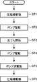
ここで、本実施形態のガス供給装置30の運転動作について、図3を参照しつつ説明する。ガス供給装置30が起動すると、圧縮機制御部35aは、圧縮機31を駆動する制御を行う(ステップST1)。また、圧縮機31が駆動されるときには、動作制御部35bは、ピストン44を下死点位置まで移動させる制御を行う(ステップST2)。すなわち、ガス室GSの容積が大きくなる方向にピストン44が移動するように、送液ポンプ46を駆動する。このとき、圧力検出器48によってガス室GS内の圧力が検出されていて、動作制御部35bは、この検出圧力が目標圧力(例えば82MPa)に維持されるように、ピストン44を移動させるようにしてもよい。なお、圧縮機制御部35aが圧縮機31を駆動する制御を行うときに、動作制御部35bは、圧力検出器48の検出圧力によらず、ピストン44を下死点位置まで移動させるための制御を行うようにしてもよい。この場合、ピストン44が下死点位置まで移動した状態で、検出圧力が目標圧力(例えば82MPa)になると、圧縮機制御部35aは圧縮機31を停止する制御を行う。いずれの場合であっても、ガス室GS内が目標圧力となった状態で、ピストン44が下死点位置に位置づけられる。
その後、ディスペンサ11から車両BのタンクCにガスの充填を開始すると(ステップST3)、動作制御部35bは、ピストン44がガス室GS側に向かってスライドするように、送液ポンプ46を駆動する(ステップST4)。すなわち、圧縮機31が駆動されていない状態で、ガス室GSに設けられた圧力検出器48の検出圧力が目標圧力よりも低下し始めると、動作制御部35bは、ピストン44が上死点位置に向けて移動するように送液ポンプ46を駆動する制御を行う。これにより、ガス室GSの容積が次第に小さくなるため、検出圧力が目標圧力に近づくようになる。したがって、ガス室GS内のガス圧力と、ディスペンサ11内におけるガス圧力との差圧によってタンクCにガス充填を行う場合でも、ガス室GS内の圧力が維持される。このため、本実施形態のガス供給方法によれば、蓄圧器を用いた差圧充填に比べて、ガス供給量が低下しないようにすることができる。
動作制御部35bは、液を液室LSに送出する方向に送液ポンプ46を駆動した後は、液を液室LSからタンク45に戻す方向に送液ポンプ46を駆動する(ステップST5)。これにより、ピストン44は下死点位置に向けて移動するため、圧力検出器48の検出圧力が低下し始める。これにより、圧縮機制御部35aは、圧縮機31を起動する(ステップST6)。そして、ピストン44が下死点位置に位置づけられた状態で、圧力検出器48の検出圧力が目標圧力になると、圧縮機制御部35aは圧縮機31を停止する。これによりシリンダ33内にガスが満充填された状態となる。
以上説明したように、本実施形態では、シリンダ本体43内からガスが流出する際に、ガス室GSからシリンダ33の外方へガスが流出するのに合わせて、ガス室GS内の容積が小さくなるようにピストン44が動作する。すなわち、シリンダ33は、ピストン44が動作することによってガス室GS内の容積を減少させる。このため、ガスがガス室GSから流出する際に、シリンダ33内のガス圧力が低下する割合を小さくすることができる。したがって、一定の容積を有する圧力容器によって構成された従来の蓄圧器に比べて、ガス圧力が下がり難くなるため、差圧充填によるガス供給量を増やすことができる。このため、ディスペンサ11に向けて供給できるガス量を確保することができる。しかも、一定の容積を有する圧力容器によって構成された従来の蓄圧器で所定の差圧を確保する場合と異なり、シリンダ33が大型化しない。したがって、ガス供給装置30が大型化することを防止することができる。
また本実施形態では、シリンダ33内のガスがディスペンサ11に向けて供給されるときに圧力検出器48によってガス圧力が検出されている。そして、動作制御部35bは、この検出圧力の値が維持されるようにピストン44を動作させるための制御を行う。このため、シリンダ33内のガス圧力とディスペンサ11でのガス圧力との間の差圧が維持されるため、ディスペンサ11に向けて流れるガスの流量を維持することができる。
また本実施形態では、シリンダ33内に封入された液体の圧力によって、ピストン44が動作する。このため、液体への押圧力を調整することより、液体の押圧力に応じてピストン44の移動量を調整することができる。したがって、ピストン44の移動量を精度よく調整することができる。
また本実施形態では、ピストン44の動作時においても、液室LSとガス室GSとがオーバーラップしないため、ガスに液体が接触することを防止することができる。したがって、ディスペンサ11に向けて供給されるガスに液体が混ざることを防止することができる。
また本実施形態では、シリンダ33が、液室LSがガス室GSの下になる姿勢で配置されているため、ガスにピストン44の自重がかかることを防止することができる。
なお、本発明は、前記実施形態に限られるものではなく、その趣旨を逸脱しない範囲で種々変更、改良等が可能である。例えば、前記実施形態では、ガスがガス室GSから流出する際に、それに応じてピストン44を上死点位置に向けて移動させる。このとき、圧力検出器48によって検出されたガス室GS内の圧力が目標圧力に維持されるように、動作制御部35bが送液ポンプ46を駆動制御する。しかしながら、本発明の実施形態は、この構成に限られない。例えば、圧力検出器48によってガス室GS内の圧力を検出することなく、送液ポンプ46を駆動するようにしてもよい。この場合でも、従来のごとく、蓄圧器を用いた差圧充填に比べれば、ガス供給量を増大させることができる。
また、前記実施形態では、シリンダ本体43に設けられた圧力検出器48による検出圧力に基づいて、検出圧力が目標圧力を維持するように送液ポンプ46を駆動する構成としたが、これに限られるものではない。例えば、図4に示すように、供給路40にも圧力検出器52が設けられていて、動作制御部35bは、ガスがガス室GSから流出するときに、この圧力検出器52の検出圧力が目標圧力を維持するように送液ポンプ46を駆動制御する構成であってもよい。この場合、シリンダ本体43の圧力検出器48を省略してもよい。
また、前記実施形態では、ガス室GSがピストン44の上側に位置して、ピストン44が最も上の位置に来たときが上死点位置となり、液室LSがピストン44の下側に位置して、ピストン44が最も下の位置に来たときが下死点位置となる構成としたが、これに限られるものではない。例えば、シリンダ33は、ピストン44が水平方向に移動する姿勢で配設されていてもよい。この場合、ガス室GSの容積が最も小さくなる上死点位置と、ガス室GSの容積が最も大きくなる下死点位置は、水平方向に並ぶことになる。また、シリンダ33は、ピストン44の下側の空間がガス室GSとなり、ピストン44の上側の空間が液室LSとなる姿勢で設置されていてもよい。
また、前記実施形態では、ガス供給装置が水素ガスを供給する例について説明したが、水素ガスに限られるものではない。
ここで、前記実施形態について概説する。
(1)前記実施形態に係るガス供給装置は、ガスを圧縮する圧縮機と、ガス室を区画するピストンを有し、前記ガス室に前記圧縮機によって圧縮されたガスが導入されるシリンダと、前記ガス室内のガスがディスペンサに向けて供給されるのに応じて、前記ガス室内の容積が小さくなるように前記ピストンを動作させるための制御を行う動作制御部と、を備えているガス供給装置である。
前記ガス供給装置では、シリンダ内からガスが流出する際に、ガス室からシリンダの外方へガスが流出するのに合わせて、ガス室内の容積が小さくなるようにピストンが動作する。すなわち、シリンダは、ピストンが動作することによってガス室内の容積を減少させる。このため、ガスがガス室から流出する際に、シリンダ内のガス圧力が低下する割合を小さくすることができる。したがって、一定の容積を有する圧力容器によって構成された従来の蓄圧器に比べて、ガス圧力が下がり難くなるため、ガス供給量を増やすことができる。このため、ディスペンサに向けて供給できるガス量を確保することができる。しかも、一定の容積を有する圧力容器によって構成された従来の蓄圧器と異なり、シリンダが大型化しない。したがって、ガス供給装置が大型化することを防止することができる。
(2)前記ガス供給装置は、前記ガス室内のガスの圧力又は前記シリンダの下流側でのガスの圧力を検出する圧力検出器を備えていてもよい。この場合、前記動作制御部は、前記圧力検出器による検出圧力の値が維持されるように、前記ピストンを動作させるための制御を行うように構成されていてもよい。
この態様では、シリンダ内のガスがディスペンサに向けて流出するときに圧力検出器によってガス圧力が検出されており、動作制御部は、この検出圧力の値が維持されるようにピストンを動作させる。このため、シリンダ内のガス圧力とディスペンサでのガス圧力との間の差圧が維持されるため、ディスペンサに向けて流れるガスの流量を維持することができる。
(3)前記シリンダ内には、前記ピストンを駆動するための液体が封入された液室を備えていてもよい。この場合、前記シリンダは、前記液室の液体の圧力によって前記ピストンを動作させるように構成されていてもよい。
この態様では、シリンダ内に封入された液体を押圧することによって、ピストンが動作する。このため、液体への押圧力を調整することよってピストンの移動量を調整することができる。したがって、ピストンの移動量を精度よく調整することができる。
(4)前記シリンダは、前記シリンダ内における液室と前記ガス室とがオーバーラップしないように構成されていてもよい。
この態様では、前記ピストンの移動時においても液室とガス室がオーバーラップしないため、ガスに液体が接触することを防止することができる。したがって、ディスペンサに向けて供給されるガスに液体が混ざることを防止することができる。
(5)前記シリンダには、前記液室に前記液体を流入させ、前記液室から前記液体を流出させる出入ポートが設けられていてもよい。この態様では、出入ポートを通じて液体が出入りし、これにより、ピストンをストロークさせることができる。
(6)前記シリンダは、前記液室が前記ガス室の下になる姿勢で配置されていてもよい。この態様では、ガス室内のガスにピストンの自重がかかることを防止することができる。
(7)前記実施形態のガス供給方法は、圧縮機から吐出されたガスをシリンダのガス室内に導入し、前記ガス室内のガスがディスペンサに向けて供給されるのに応じて、前記ガス室内の容積が小さくなるようにピストンを動作させるガス供給方法である。
(8)前記ガス供給方法において、前記ガス室内のガスの圧力又は前記シリンダの下流側でのガスの圧力を検出し、前記ガス室内のガスを前記ディスペンサに向けて供給する際に、前記ガスの検出圧力が維持されるように前記ピストンを動作させてもよい。
(9)前記ガス供給方法において、圧縮機を駆動しながら、前記ガス室内の容積が大きくなる方向に前記ピストンが動作する際に、検出された前記ガス室内の圧力が維持されるように前記ピストンを動作させてもよい。これにより、圧縮機の吐出圧力を一定に保つことができ、圧縮機の機械効率の向上を図ることができる。
(10)前記ガス供給方法において、圧縮機から吐出されたガスを前記ガス室に供給する際に、前記ガス室内の容積が大きくなる方向に前記ピストンを動作させてもよい。これにより、圧縮機の吐出圧力を下げることができるとともに、吐出後のガス温度を低く抑えることができる。また、プレクーラの負荷低下、アフタークーラの小型化や省略が可能となる。
以上説明したように、前記実施形態によれば、ガス供給装置が大型化することを防止しつつ、ディスペンサに向けて供給できるガス量を確保することができる。
Claims (11)
- ガスを圧縮する圧縮機と、
ガス室を区画するピストンを有し、前記ガス室に前記圧縮機によって圧縮されたガスが導入されるシリンダと、
前記ガス室内のガスがディスペンサに向けて供給されるのに応じて、前記ガス室内の容積が小さくなるように前記ピストンを動作させるための制御を行う動作制御部と、を備えているガス供給装置。 - 前記ガス室内のガスの圧力又は前記シリンダの下流側でのガスの圧力を検出する圧力検出器を備えており、
前記動作制御部は、前記圧力検出器による検出圧力の値が維持されるように、前記ピストンを動作させるための制御を行うように構成されている請求項1に記載のガス供給装置。 - 前記シリンダ内には、前記ピストンを駆動するための液体が封入された液室を備えており、
前記シリンダは、前記液室の液体の圧力によって前記ピストンを動作させるように構成されている請求項1又は2に記載のガス供給装置。 - 前記シリンダは、前記シリンダ内における前記液室と前記ガス室とがオーバーラップしないように構成されている請求項3に記載のガス供給装置。
- 前記シリンダには、前記液室に前記液体を流入させ、前記液室から前記液体を流出させる出入ポートが設けられている請求項4に記載のガス供給装置。
- 前記シリンダは、前記液室が前記ガス室の下になる姿勢で配置されている請求項4に記載のガス供給装置。
- 前記シリンダは、前記液室が前記ガス室の下になる姿勢で配置されている請求項5に記載のガス供給装置。
- 圧縮機から吐出されたガスをシリンダのガス室内に導入し、
前記ガス室内のガスがディスペンサに向けて供給されるのに応じて、前記ガス室内の容積が小さくなるようにピストンを動作させるガス供給方法。 - 前記ガス室内のガスの圧力又は前記シリンダの下流側でのガスの圧力を検出し、
前記ガス室内のガスを前記ディスペンサに向けて供給する際に、前記ガスの検出圧力が維持されるように前記ピストンを動作させる請求項8に記載のガス供給方法。 - 圧縮機を駆動しながら、前記ガス室内の容積が大きくなる方向に前記ピストンが動作する際に、検出された前記ガス室内の圧力が維持されるように前記ピストンを動作させる請求項9に記載のガス供給方法。
- 圧縮機から吐出されたガスを前記ガス室に供給する際に、前記ガス室内の容積が大きくなる方向に前記ピストンを動作させる請求項8又は9に記載のガス供給方法。
Applications Claiming Priority (2)
| Application Number | Priority Date | Filing Date | Title |
|---|---|---|---|
| JP2016-009411 | 2016-01-21 | ||
| JP2016009411A JP2017129221A (ja) | 2016-01-21 | 2016-01-21 | ガス供給装置及びガス供給方法 |
Publications (1)
| Publication Number | Publication Date |
|---|---|
| WO2017126672A1 true WO2017126672A1 (ja) | 2017-07-27 |
Family
ID=59361870
Family Applications (1)
| Application Number | Title | Priority Date | Filing Date |
|---|---|---|---|
| PCT/JP2017/001964 Ceased WO2017126672A1 (ja) | 2016-01-21 | 2017-01-20 | ガス供給装置及びガス供給方法 |
Country Status (2)
| Country | Link |
|---|---|
| JP (1) | JP2017129221A (ja) |
| WO (1) | WO2017126672A1 (ja) |
Citations (7)
| Publication number | Priority date | Publication date | Assignee | Title |
|---|---|---|---|---|
| US5253682A (en) * | 1991-12-13 | 1993-10-19 | Haskett Carl E | Free piston gas delivery apparatus and method |
| US5454408A (en) * | 1993-08-11 | 1995-10-03 | Thermo Power Corporation | Variable-volume storage and dispensing apparatus for compressed natural gas |
| JPH0979495A (ja) * | 1995-09-19 | 1997-03-25 | Tokyo Gas Co Ltd | ガス供給装置 |
| JP2002364396A (ja) * | 2001-06-05 | 2002-12-18 | Tokico Ltd | 燃料混合充填システム |
| JP2003148688A (ja) * | 2001-11-13 | 2003-05-21 | Hitachi Constr Mach Co Ltd | 圧縮天然ガス供給装置と圧縮天然ガス供給システムと圧縮天然ガス供給方法 |
| JP2003148697A (ja) * | 2001-11-07 | 2003-05-21 | Toho Gas Co Ltd | 天然ガススタンドシステム |
| JP2012237437A (ja) * | 2011-04-26 | 2012-12-06 | Kobe Steel Ltd | 水素ステーション |
-
2016
- 2016-01-21 JP JP2016009411A patent/JP2017129221A/ja active Pending
-
2017
- 2017-01-20 WO PCT/JP2017/001964 patent/WO2017126672A1/ja not_active Ceased
Patent Citations (7)
| Publication number | Priority date | Publication date | Assignee | Title |
|---|---|---|---|---|
| US5253682A (en) * | 1991-12-13 | 1993-10-19 | Haskett Carl E | Free piston gas delivery apparatus and method |
| US5454408A (en) * | 1993-08-11 | 1995-10-03 | Thermo Power Corporation | Variable-volume storage and dispensing apparatus for compressed natural gas |
| JPH0979495A (ja) * | 1995-09-19 | 1997-03-25 | Tokyo Gas Co Ltd | ガス供給装置 |
| JP2002364396A (ja) * | 2001-06-05 | 2002-12-18 | Tokico Ltd | 燃料混合充填システム |
| JP2003148697A (ja) * | 2001-11-07 | 2003-05-21 | Toho Gas Co Ltd | 天然ガススタンドシステム |
| JP2003148688A (ja) * | 2001-11-13 | 2003-05-21 | Hitachi Constr Mach Co Ltd | 圧縮天然ガス供給装置と圧縮天然ガス供給システムと圧縮天然ガス供給方法 |
| JP2012237437A (ja) * | 2011-04-26 | 2012-12-06 | Kobe Steel Ltd | 水素ステーション |
Also Published As
| Publication number | Publication date |
|---|---|
| JP2017129221A (ja) | 2017-07-27 |
Similar Documents
| Publication | Publication Date | Title |
|---|---|---|
| US10883662B2 (en) | Gas supply device, hydrogen station, and gas supply method | |
| US6799698B2 (en) | Liquid material supply system | |
| EP2998579B1 (en) | Ultra-high pressure generator | |
| CN102947593B (zh) | 双膜片泵 | |
| US9810374B2 (en) | Gas-filling apparatus and method for filling gas | |
| EP1864022B1 (en) | Pressure accumulating apparatus | |
| US20070177998A1 (en) | Liquid chemical supply system | |
| US7063513B2 (en) | Liquid chromatograph pump with dual cylinders and dual plungers | |
| US10590634B2 (en) | Pressurized potable water system with conformal shape water storage tank | |
| US20120301328A1 (en) | Multistage piston compressor | |
| CN103492785A (zh) | 氢站 | |
| CN104676241A (zh) | 气体填充装置和气体填充方法 | |
| RU2006141599A (ru) | Многоцилиндровый насос с гидроприводом | |
| KR20070057813A (ko) | 가스상 매체를 압축하기 위한 방법 및 장치 | |
| JP6753532B2 (ja) | 送液装置 | |
| US6851449B2 (en) | Spring-loaded oil overflow valve for diaphragm compressors | |
| US10718324B2 (en) | Bellows pump apparatus | |
| US3743444A (en) | Oil-diaphragm slurry pump | |
| KR100363748B1 (ko) | 펌프의 맥동 감쇠장치 | |
| WO2017126672A1 (ja) | ガス供給装置及びガス供給方法 | |
| JP2018009630A (ja) | 二酸化炭素の供給方法および供給システム | |
| JP2008291848A (ja) | 液体クロマトグラフ用ポンプ | |
| WO2003002876A1 (en) | Booster | |
| US8397681B2 (en) | Expansion tank for vehicle cooling system | |
| WO2009157026A1 (en) | Equipment for filling with liquid a diaphragm pump chamber |
Legal Events
| Date | Code | Title | Description |
|---|---|---|---|
| 121 | Ep: the epo has been informed by wipo that ep was designated in this application |
Ref document number: 17741549 Country of ref document: EP Kind code of ref document: A1 |
|
| NENP | Non-entry into the national phase |
Ref country code: DE |
|
| 122 | Ep: pct application non-entry in european phase |
Ref document number: 17741549 Country of ref document: EP Kind code of ref document: A1 |