WO2017126449A1 - ステアリングホイール - Google Patents
ステアリングホイール Download PDFInfo
- Publication number
- WO2017126449A1 WO2017126449A1 PCT/JP2017/001136 JP2017001136W WO2017126449A1 WO 2017126449 A1 WO2017126449 A1 WO 2017126449A1 JP 2017001136 W JP2017001136 W JP 2017001136W WO 2017126449 A1 WO2017126449 A1 WO 2017126449A1
- Authority
- WO
- WIPO (PCT)
- Prior art keywords
- steering
- engagement
- adhesive
- engagement hook
- steering wheel
- Prior art date
- Legal status (The legal status is an assumption and is not a legal conclusion. Google has not performed a legal analysis and makes no representation as to the accuracy of the status listed.)
- Ceased
Links
Images


Classifications
-
- B—PERFORMING OPERATIONS; TRANSPORTING
- B62—LAND VEHICLES FOR TRAVELLING OTHERWISE THAN ON RAILS
- B62D—MOTOR VEHICLES; TRAILERS
- B62D1/00—Steering controls, i.e. means for initiating a change of direction of the vehicle
- B62D1/02—Steering controls, i.e. means for initiating a change of direction of the vehicle vehicle-mounted
- B62D1/04—Hand wheels
- B62D1/06—Rims, e.g. with heating means; Rim covers
-
- F—MECHANICAL ENGINEERING; LIGHTING; HEATING; WEAPONS; BLASTING
- F16—ENGINEERING ELEMENTS AND UNITS; GENERAL MEASURES FOR PRODUCING AND MAINTAINING EFFECTIVE FUNCTIONING OF MACHINES OR INSTALLATIONS; THERMAL INSULATION IN GENERAL
- F16B—DEVICES FOR FASTENING OR SECURING CONSTRUCTIONAL ELEMENTS OR MACHINE PARTS TOGETHER, e.g. NAILS, BOLTS, CIRCLIPS, CLAMPS, CLIPS OR WEDGES; JOINTS OR JOINTING
- F16B19/00—Bolts without screw-thread; Pins, including deformable elements; Rivets
-
- F—MECHANICAL ENGINEERING; LIGHTING; HEATING; WEAPONS; BLASTING
- F16—ENGINEERING ELEMENTS AND UNITS; GENERAL MEASURES FOR PRODUCING AND MAINTAINING EFFECTIVE FUNCTIONING OF MACHINES OR INSTALLATIONS; THERMAL INSULATION IN GENERAL
- F16B—DEVICES FOR FASTENING OR SECURING CONSTRUCTIONAL ELEMENTS OR MACHINE PARTS TOGETHER, e.g. NAILS, BOLTS, CIRCLIPS, CLAMPS, CLIPS OR WEDGES; JOINTS OR JOINTING
- F16B5/00—Joining sheets or plates, e.g. panels, to one another or to strips or bars parallel to them
- F16B5/06—Joining sheets or plates, e.g. panels, to one another or to strips or bars parallel to them by means of clamps or clips
-
- F—MECHANICAL ENGINEERING; LIGHTING; HEATING; WEAPONS; BLASTING
- F16—ENGINEERING ELEMENTS AND UNITS; GENERAL MEASURES FOR PRODUCING AND MAINTAINING EFFECTIVE FUNCTIONING OF MACHINES OR INSTALLATIONS; THERMAL INSULATION IN GENERAL
- F16B—DEVICES FOR FASTENING OR SECURING CONSTRUCTIONAL ELEMENTS OR MACHINE PARTS TOGETHER, e.g. NAILS, BOLTS, CIRCLIPS, CLAMPS, CLIPS OR WEDGES; JOINTS OR JOINTING
- F16B13/00—Dowels or other devices fastened in walls or the like by inserting them in holes made therein for that purpose
- F16B13/04—Dowels or other devices fastened in walls or the like by inserting them in holes made therein for that purpose with parts gripping in the hole or behind the reverse side of the wall after inserting from the front
Definitions
- the present invention relates to a steering wheel coupled to a steering shaft.
- the finisher is attached to the rim core bar by engaging the latch part of the finisher with the through hole of the rim core bar and pressing the latch part with the resin ring in the through hole. Steering wheel is described.
- the resin ring is elastically deformable. For this reason, the resin ring cannot restrict
- the present invention has been made in view of the above-described facts, and an object of the present invention is to provide a steering wheel that can restrict the decorative member from being detached from the steering body.
- a first aspect of the present disclosure includes a steering body connected to a steering shaft, a decoration member that decorates the steering body, and one of the steering shaft and the decoration member.
- the engagement member is attached to the steering body by being engaged with the other of the steering body and the decoration member, and the engagement with respect to the other of the steering body and the decoration member.
- a restricting member that restricts disengagement of the combined member.
- the decoration member is attached to the steering body using the engagement member. Engagement of the engagement member is restricted by the restriction member. This restricts the decorative member from being detached from the steering body.
- a second aspect of the present disclosure is provided in the engagement member, engaged with the other of the steering body and the decoration member, and disengaged from the other of the steering body and the decoration member.
- the second aspect of the present disclosure includes an engagement portion that is engaged with the other of the steering body and the decorating member, and is disengaged by moving to the disengaged side.
- the restricting member restricts the movement of the engaging portion to the side where the engagement is released. Therefore, the decorative member is restricted from being detached from the steering body.
- the restriction member is a cured material.
- a hardened material is used as the limiting member.
- the cured material does not prevent the engaging member from engaging the other of the steering body and the decorative member before curing.
- a limiting member restrict
- FIG. 2 is a schematic cross-sectional view of a rim portion taken along line 2-2 in FIG. It is a schematic perspective view which shows a wooden member and an engagement hook. It is a schematic sectional drawing of the principal part of a base
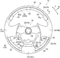
- FIG. 1 shows a steering wheel 10 according to the first embodiment.
- the steering wheel 10 is disposed on the vehicle front side of a seat (driver's seat) on which a passenger who operates a vehicle (not shown) is seated, and is used for steering the vehicle.
- FIG. 1 shows the steering wheel 10 in a plan view from the occupant side.
- the steering wheel 10 includes an annular rim portion 12, a plurality of spoke portions 14 provided on the rim portion 12, and a boss portion 16 provided on an axial center portion of the rim portion 12.
- the steering wheel 10 also includes a metal core 18 that forms a skeleton.
- the core metal 18 includes a rim core metal part 20 disposed in the rim part 12, a spoke core metal part 22 disposed in the spoke part 14, and a boss core metal part 24 disposed in the boss part 16.
- the core metal part 20 and the boss core metal part 24 are connected by a spoke core metal part 22.
- FIG. 1 shows a straight-ahead steering position in a state where the steering wheel 10 moves the vehicle straight.
- the upper side in the axial direction (the steering upward direction) of the steering wheel 10 is indicated by an arrow UP
- the circumferential direction (the steering circumferential direction) of the steering wheel 10 is indicated by an arrow L.
- the radially outward direction (the steering radially outward direction) of the steering wheel 10 is illustrated by an arrow R.
- the steering wheel 10 is provided with a wooden member (saddle part) 30 as a decoration member on the rim part 12.
- the spoke portion 14 is provided with a spoke portion 14A on the left side when viewed from the occupant side, a spoke portion 14B on the right side, and a spoke portion 14C on the occupant side at the straight steering position of the steering wheel 10.
- the wood member 30A is disposed between the spoke portions 14A and 14B of the rim portion 12
- the wood member 30B is disposed between the spoke portions 14A and 14C
- the wood member 30C is disposed between the spoke portions 14B and 14C. Is placed.
- the wooden members 30A, 30B, and 30C have the same basic configuration for attachment to the rim portion 12.
- the wooden members 30A, 30B, and 30C will be described as the wooden member 30 without distinction.
- FIG. 2 shows a cross section of the rim portion 12 cut along the steering radial direction.
- the rim portion 12 includes a base body 32 as a steering body.
- the base 32 is made of a resin material such as urethane.
- the rim cored bar 20 is accommodated in the base body 32 by insert molding.
- the wooden member 30 is formed in an arc shape along the steering circumferential direction in a plan view.
- the wood member 30 has a substantially radial arc-shaped cross section in the steering radial direction, and is opposed to the base body 32 in the range from the steering radial inner direction to the steering upward direction.
- the base 32 has a stepped portion 34 formed at a portion where the wooden member 30 is opposed.
- the step 34 is formed along the steering circumferential direction corresponding to the wooden member 30.
- the stepped portion 34 is formed with a facing surface 34A directed in the steering upward direction on the steering radial inward side of the base body 32, and a facing surface 34B directed in the steering radial inward side on the steering upward direction side of the base body 32. Is formed.
- the step portion 34 is formed with a facing surface 34C facing the steering upward direction at a position on the steering upward direction side of the facing surface 34A between the facing surface 34A and the facing surface 34A.
- the end portion 36A on the steering radial inner side faces the facing surface 34A of the base body 32
- the end portion 36B on the steering radial outer side faces the facing surface 34B of the base body 32. Then, it is disposed on the stepped portion 34 of the base 32.
- the step portion 34 of the base body 32 is filled with the wooden member 30, the rim core metal portion 20 is covered with the wooden member 30 and the base body 32, and the cross-sectional outer shape is substantially circular.
- the wooden member 30 is provided with attachment portions 40 at both ends in the steering circumferential direction, and is attached and fixed to the base 32 at the attachment portions 40.
- the attachment portion 40 may be provided at one or a plurality of locations in the intermediate portion of the wooden member 30 in the steering circumferential direction.
- FIG. 3 shows a surface of the wooden member 30 on the base 32 side (hereinafter, a surface opposite to the front surface 36C, referred to as a back surface 36D).
- a tenon portion 44 is provided in the wood member 30 at a position corresponding to the attachment portion 40 of the back surface 36D.
- the tenon portion 44 has a substantially rectangular block shape protruding from the back surface 36 ⁇ / b> D of the wooden member 30.
- the tenon portion 44 faces the facing surface 34 ⁇ / b> C of the stepped portion 34.
- an engagement hook 50 as an engagement member is attached to the tenon portion 44 of the wooden member 30.
- the engagement hook 50 is made of a metal material such as stainless steel, and a band portion 52, a leg portion 54, and a claw portion 56 as an engagement portion are formed.
- the band portion 52 is formed in a rectangular substantially frame shape corresponding to the outer periphery of the tenon portion 44.
- the engagement hook 50 is attached to the wooden member 30 with the band portion 52 surrounding the tenon portion 44.
- the engagement hook 50 is preferably attached to the wooden member 30 so that the band portion 52 can tighten the periphery of the tenon portion 44.
- a through hole (not shown) is formed in the tenon portion 44 of the wooden member 30 along the steering radial direction. With the engagement hook 50 attached, the locking pin 60 is inserted into the through hole from the steering radial outer side. Is inserted. As shown in FIG. 3, a long hole 52 ⁇ / b> A is formed in the band portion 52 of the engagement hook 50 on the outer side of the steering diameter. The band portion 52 is formed with a rectangular hole (not shown) corresponding to the opening of the through hole of the tenon portion 44 on the steering radial inner side.
- the locking pin 60 is provided with a ring portion 60A on one end side and an end portion 60B that is folded back toward the ring portion 60A on the other end side.
- the outer diameter of the ring portion 60 ⁇ / b> A is slightly larger than the inner diameter of the through hole of the tenon portion 44.
- the end portion 60 ⁇ / b> B corresponds to a long hole 52 ⁇ / b> A formed in the band portion 52 of the engagement hook 50.
- the locking pin 60 is inserted from the ring portion 60A into the through hole of the tenon portion 44 to which the band portion 52 of the engagement hook 50 is mounted until the ring portion 60A protrudes from the through hole.
- the ring portion 60 ⁇ / b> A protruding from the tenon portion 44 enters the rectangular hole formed in the band portion 52 of the engagement hook 50.
- the locking pin 60 enters an elongated hole 52 ⁇ / b> A formed in the band portion 52 of the engagement hook 50 at the end portion 60 ⁇ / b> B and abuts on the surface on the steering radial outer side of the tenon portion 44.
- the locking pin 60 is engaged with the tenon portion 44 while restricting movement in the axial direction and the direction intersecting the axial direction. Further, the movement of the band portion 52 in the circumferential direction outward (direction intersecting the steering shaft direction) of the tenon portion 44 is prevented, and the locking pin 60 moves the tenon portion 44 in the extraction direction (steering shaft direction). The movement is prevented and the engagement hook 50 is fixed to the wooden member 30.
- the leg portions 54 of the engagement hook 50 are formed in a band plate shape and are extended in pairs from both sides of the band portion 52 in the steering circumferential direction.
- the pair of leg portions 54 includes a base portion 54A that extends from the band portion 52 in a direction approaching each other, and the distal end portions of the respective base portions 54A are bent substantially at right angles to extend substantially in parallel.
- the pair of leg portions 54 are elastically deformed and can swing in directions in which the tip portions approach each other.
- the claw portion 56 of the engagement hook 50 is formed by bending the tip portions of the leg portions 54 in directions away from each other along the steering circumferential direction. Further, the claw portion 56 is bent so as to have an obtuse angle with respect to the leg portion 54, so that the tip is inclined toward the band portion 52 side (wood member 30 side), that is, the steering upward direction. Further, the claw portion 56 is narrowed at the interval between the tips thereof by the swinging of the leg portion 54.
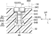
- FIGS. 4A and 4B show schematic cross sections of the base body 32 along the steering circumferential direction.
- the base 32 is provided with a bottomed mounting hole 62 at a position facing the tenon portion 44 of the wooden member 30 on the facing surface 34 ⁇ / b> C of the step portion 34.
- 4A shows a state where the claw portion 56 of the engagement hook 50 is inserted into the attachment hole 62
- FIG. 4B shows a state where the engagement hook 50 is inserted into the attachment hole 62.
- the attachment hole 62 has a recessed portion 64A corresponding to the band portion 52 of the engagement hook 50 attached to the tenon portion 44 of the wood member 30 opened in the facing surface 34C. ing. Further, the attachment hole 62 is formed with an enlarged diameter portion 64 ⁇ / b> B corresponding to the claw portion 56 of the engagement hook 50 inside the base body 32. Further, in the mounting hole 62, the bottom portion of the recessed portion 64 ⁇ / b> A and the enlarged diameter portion 64 ⁇ / b> B are communicated with each other by a shaft hole 64 ⁇ / b> C corresponding to the pair of leg portions 54 of the engagement hook 50.
- the enlarged diameter portion 64B has an inner diameter larger than the distance between the tips of the claw portions 56 in a state where the pair of leg portions 54 of the engagement hook 50 is not swung.
- the shaft hole 64C has an inner diameter slightly larger than the distance between the tips of the claw portions 56 in a state where the pair of leg portions 54 of the engagement hook 50 are swung so as to contact each other.
- the mounting hole 62 has an inner diameter at the end of the shaft hole 64C on the side of the expanded diameter portion 64B gradually increased toward the expanded diameter portion 64B.
- the mounting hole 62 includes the expanded diameter portion 64B and the axial hole 64C.
- An inclined surface 64D is formed between the two. The tip of the claw portion 56 in a state where the pair of leg portions 54 of the engagement hook 50 is not swung is brought into contact with the inclined surface 64D.
- the engagement hook 50 is prevented from moving in the axial direction by being brought into contact with the bottom surface of the recessed portion 64 ⁇ / b> A of the band portion 52 and the inclined surface 64 ⁇ / b> D at the tip of the claw portion 56, and is fixed to the base body 32.
- the engagement hook 50 is swung so that the pair of leg portions 54 are in contact with each other, whereby when the interval between the tips of the claw portions 56 is narrowed, the tips of the claw portions 56 are separated from the inclined surface 64D, The engagement with the base body 32 is released.
- the engagement hook 50 can be pulled out from the attachment hole 62 by releasing the engagement with the base body 32.
- an adhesive 66 is provided in the mounting hole 62 as a limiting member.
- the adhesive 66 is disposed in the enlarged diameter portion 64 ⁇ / b> B of the attachment hole 62, and is cured in a state where the adhesive 66 enters between the pair of leg portions 54.
- a pair of leg part 54 is inhibited from moving to the direction which leaves
- the engagement hook 50 is restricted from being pulled out from the attachment hole 62 by the hardened adhesive 66, and fixes the wooden member 30 to the base body 32.
- the adhesive 66 any adhesive can be applied, but an adhesive having low fluidity is more preferable than an adhesive having high fluidity. That is, the adhesive 66 is more preferably an adhesive having a higher viscosity than an adhesive having a low viscosity. Moreover, it is preferable that the adhesive 66 has a characteristic that it does not soften under the use environment of the steering wheel 10 after being cured.
- the adhesive 66 is injected into the mounting hole 62 of the base body 32 before the engagement hook 50 is inserted.
- the amount of the adhesive 66 to be injected varies depending on the viscosity (fluidity) of the adhesive 66, but when the claw portion 56 of the engagement hook 50 is inserted and arranged in the enlarged diameter portion 64B of the mounting hole 62, The amount is at least between the ends of the pair of legs 54 on the claw 56 side.
- the engaging hook 50 is inserted from the claw portion 56 into the mounting hole 62 into which the adhesive 66 has been injected while being fixed to the wooden member 30.
- the leg portion 54 of the engagement hook 50 is inserted in a state where the tips of the claw portions 56 are swung so as to approach each other (a state where the end portions on the side of the claw portions 56 are in contact with each other).
- the engaging hook 50 passes the shaft hole 64C, without the claw part 56 being blocked by the inner surface of the shaft hole 64C.
- the adhesive 66 injected into the mounting hole 62 remains in the shaft hole 64C, it is pushed into the enlarged diameter portion 64B by the claw portion 56.
- the engaging hook 50 has a mounting hole 62 until the claw 56 reaches the diameter-expanded portion 64B of the mounting hole 62, that is, until the base portion 54A of the leg portion 54 contacts the bottom surface of the recessed portion 64A. After that, the swinging of the leg portion 54 is released. As a result, as shown in FIG. 4B, each of the claw portions 56 abuts the inclined surface 64D, and the engagement hook 50 is engaged with the base body 32 by restricting the movement of the mounting hole 62 in the axial direction.
- the wooden member 30 provided with the mating hook 50 is assembled and fixed to the base 32.
- the adhesive 66 injected into the mounting hole 62 is pushed into the enlarged diameter portion 64B and enters between the leg portions 54. Thereafter, the adhesive 66 is cured as time elapses.
- the engagement hook 50 is restricted from swinging in the direction of releasing the engagement of the claw 56 as the adhesive 66 entering between the pair of legs 54 is cured. As a result, the engagement hook 50 is maintained in a state where the pull-out from the attachment hole 62 is restricted.
- the steering wheel 10 is limited in that the wooden member 30 attached to the base body 32 is detached from the base body 32. At this time, the steering wheel 10 can use the engagement hook 50 to increase the attachment strength of the wooden member 30 to the base body 32 as compared with the case where the wooden member 30 is fixed to the base body 32 only with an adhesive.
- the adhesive 66 is used as the cured material, so that the wooden member 30 is firmly fixed as compared with the case where only the engagement hook 50 is used without using the adhesive 66.
- the adhesive 66 injected into the mounting hole 62 adheres not only to the leg portion 54 of the engagement hook 50 but also to the inner surface of the enlarged diameter portion 64B, so that it hardens in the enlarged diameter portion 64B.
- the lump of adhesive 66 does not move within the enlarged diameter portion 64B. Therefore, the generation of abnormal noise due to the turning operation of the steering wheel 10 is suppressed.
- the wooden member 30 as a decorating member is attached to the inner side of the rim portion 12 in the steering radial direction (range from the steering radial inner direction to the steering upward direction)
- the position where the wooden member is attached is not limited to this.
- the wood member may be attached to an arbitrary position on the outer periphery of the rim portion 12 in the cross section along the steering radial direction of the rim portion 12, and is divided into a plurality of portions and attached to the outer periphery of the rim portion 12. Also good.
- the wooden member is not limited to the rim portion 12 between the spoke portions 14, and may be attached to one of the spoke portion 14 and the boss portion 16, or may be attached across the rim portion 12 and the spoke portion 14. good.
- the wooden member 30 was applied as a decorating member
- the decorating member was not restricted to a wooden member, but was manufactured by the decorative member manufactured by resin molding of synthetic resin, or the resin molding of synthetic resin.
- the adhesive 66 as the limiting member may be a silicone sealant that cures by reacting with moisture in the air.
- the limiting member is not limited to the adhesive 66, and any resin material or resin material that can be cured and maintained in a cured state, such as a thermoplastic resin that cools and cures over time, such as a thermoplastic resin, can be applied. can do.
- claw part 56 as an engaging part was provided in a pair in the engaging hook 50 as an engaging member, it is not restricted to this, One or three or more engaging parts are provided. There may be. In the case where three or more claw portions 56 are provided as the engaging portions, they are arranged so that their respective tips are directed on the same circumference and radially outward. In order to release the engagement, each of the claw portions 56 may be moved inwardly in the radial direction.
- the shape of the leg portion 54 provided on the engaging member is not limited to the band plate shape, and various shapes are applicable as long as the claw portion 56 can swing so as to move in a direction approaching each other.
Landscapes
- Engineering & Computer Science (AREA)
- General Engineering & Computer Science (AREA)
- Mechanical Engineering (AREA)
- Chemical & Material Sciences (AREA)
- Combustion & Propulsion (AREA)
- Transportation (AREA)
- Steering Controls (AREA)
- Connection Of Plates (AREA)
- Dowels (AREA)
- Insertion Pins And Rivets (AREA)
Abstract
木部材(30)に設けられる係合フック(50)は、一対の脚部(54)及び脚部(54)の各々に設けられ先端が互いに離間する方向へ突出された爪部(56)を備え、脚部(54)を揺動することで爪部(56)が接近される。係合フック(50)は、予め接着剤(66)が注入された基体(32)の取付孔(62)に挿入され、爪部(56)が傾斜面(64D)に当接することで基体(32)に係合される。また、接着剤(66)は、脚部(54)の間で硬化し、爪部(56)が互いに接近する方向への脚部(54)の揺動を制限する。これにより、木部材(30)が基体(32)から外れるのが制限される。
Description
本発明は、ステアリングシャフトに連結されるステアリングホイールに関する。
特開2000-085587号公報には、フィニッシャの係止部をリム芯金の貫通孔へ係合させると共に、貫通孔内の樹脂リングにより係止部を押圧して、フィニッシャをリム芯金に取付けたステアリングホイールが記載されている。
ところで、特開2000-085587号公報では、樹脂リングが弾性変形可能にされている。このため、樹脂リングは、係止部の貫通孔への係合の解除を制限できない。
本発明は、上記事実を鑑みて成されたものであり、加飾部材がステアリング本体から外れるのを制限できるステアリングホイールを提供することを目的とする。
上記目的を達成するために、本開示の第1の態様は、ステアリングシャフトに連結されるステアリング本体と、前記ステアリング本体を加飾する加飾部材と、前記ステアリングシャフト及び前記加飾部材の一方に設けられ、前記ステアリング本体及び前記加飾部材の他方に係合されることで前記加飾部材が前記ステアリング本体に取付けられるに係合部材と、前記ステアリング本体及び前記加飾部材の他方に対する前記係合部材の係合解除を制限する制限部材と、を含む。
本開示の第1の態様では、係合部材を用いてステアリング本体に加飾部材が取付けられる。係合部材は、制限部材により係合解除が制限される。これにより、加飾部材がステアリング本体から外れるのが制限される。
本開示の第2の態様は、前記係合部材に設けられ、前記ステアリング本体及び前記加飾部材の他方に係合されると共に、前記ステアリング本体及び前記加飾部材の他方に対する係合が解除される側への移動を前記制限部材が制限する係合部を含む。
本開示の第2の態様では、ステアリング本体及び加飾部材の他方に係合され、係合が解除される側に移動することで係合を解除する係合部を含む。制限部材は、係合部の係合が解除される側への移動を制限する。従って、加飾部材がステアリング本体から外れるのが制限される。
本開示の第3の態様は、前記制限部材は、硬化した材料である。
本開示の第3の態様では、制限部材として、硬化した材料を用いる。硬化した材料は、硬化する前は、係合部材がステアリング本体及び前記加飾部材の他方に係合するのを阻害しない。また、制限部材は、硬化したことで加飾部材がステアリング本体から外れるのを制限する。
本発明によれば、加飾部材がステアリング本体から外れるのが制限される、という効果を有する。
以下、図面を参照して本発明の実施の形態を説明する。図1には、第1の実施の形態に係るステアリングホイール10を示している。ステアリングホイール10は、図示しない車両を運転操作する乗員が着座する座席(運転席)の車両前方側に配置され、車両の操舵に用いられる。図1は、ステアリングホイール10を乗員側からの平面視で示している。
ステアリングホイール10は、円環状のリム部12、リム部12に設けられた複数のスポーク部14、及びリム部12の軸心部に設けられたボス部16を含む。また、ステアリングホイール10は、骨格を形成する金属製の芯金18を備える。芯金18は、リム部12内に配置されるリム芯金部20、スポーク部14内に配置されるスポーク芯金部22及びボス部16内に配置されるボス芯金部24を備え、リム芯金部20とボス芯金部24とがスポーク芯金部22により連結されている。
ステアリングホイール10は、軸心部のボス部16のボス芯金部24が、車両の操舵装置(ステアリング装置)のステアリングシャフト26に固定され、リム部12がステアリングシャフト26の軸回りにステアリングシャフト26と一体回転可能に支持されている。なお、図1は、ステアリングホイール10が車両を直進させる状態の直進操舵位置を示している。また、以下の説明においては、ステアリングホイール10の軸方向上側(ステアリング上方向)を矢印UPで示し、ステアリングホイール10の周方向(ステアリング周方向)を矢印Lで示す。また、以下の説明においては、ステアリングホイール10の径外方向(ステアリング径外方向)を矢印Rにより例示する。
ステアリングホイール10には、リム部12に加飾部材としての木部材(杢部)30が設けられている。スポーク部14は、ステアリングホイール10の直進操舵位置において、乗員側から見て左側にスポーク部14Aが設けられ、右側にスポーク部14Bが設けられ、乗員側にスポーク部14Cが設けられている。木部材30は、リム部12のスポーク部14A、14Bの間に木部材30Aが配置され、スポーク部14A、14Cの間に木部材30Bが配置され、スポーク部14B、14Cの間に木部材30Cが配置される。なお、木部材30A、30B、30Cは、リム部12へ取付けのための基本的な構成が同様であり、以下では、木部材30A、30B、30Cを区別せずに木部材30として説明する。
図2には、ステアリング径方向に沿って切断したリム部12の断面を示している。リム部12は、ステアリング本体としての基体32を含む。基体32は、ウレタンなどの樹脂材料が用いられている。リム芯金部20は、インサート成形により基体32に収容されている。
図1に示すように、木部材30は、平面視でステアリング周方向に沿う円弧状に形成されている。また、図2に示すように、木部材30は、ステアリング径方向の断面が略円弧状に形成され、ステアリング径内方向からステアリング上方向の範囲で基体32に対向されている。
基体32は、木部材30が対向される部位に段差部34が形成されている。段差部34は、木部材30に対応されてステアリング周方向に沿って形成されている。段差部34には、基体32のステアリング径内方向側にステアリング上方向に向けられた対向面34Aが形成され、基体32のステアリング上方向側にステアリング径内方側へ向けられた対向面34Bが形成されている。また、段差部34には、対向面34Aと対向面34Aとの間に、対向面34Aよりもステアリング上方向側となる位置にステアリング上方向に向けられた対向面34Cが形成されている。
木部材30は、略円弧形状の断面において、ステアリング径内方向側の端部36Aが基体32の対向面34Aに対向され、ステアリング径外方向側の端部36Bが基体32の対向面34Bに対向されて、基体32の段差部34に配置される。これにより、リム部12は、基体32の段差部34が木部材30により埋められ、木部材30と基体32とによりリム芯金部20が被覆されると共に、断面外形が略円状とされている。
図1に示すように、木部材30は、ステアリング周方向の両端部に取付部40が設けられ、取付部40において基体32に取付けられて固定される。なお、取付部40は、木部材30のステアリング周方向の両端部に加え、木部材30のステアリング周方向の中間部の1箇所又は複数箇所に設けられても良い。
図3には、木部材30の基体32側の面(以下、表面36Cとは反対側の面。裏面36Dと言う)を示している。木部材30には、裏面36Dの取付部40に対応する位置にほぞ部44が設けられている。ほぞ部44は、木部材30の裏面36Dから突出された略矩形形状のブロック状とされている。図2に示すように、木部材30は、基体32の段差部34に配置されたときに、ほぞ部44が段差部34の対向面34Cに対向される。
図2及び図3に示すように、木部材30には、ほぞ部44に係合部材としての係合フック50が取付けられる。図3に示すように、係合フック50は、ステンレスなどの金属材料が用いられ、バンド部52、脚部54、及び係合部としての爪部56が形成されている。バンド部52は、ほぞ部44の外周に対応する矩形の略枠体状に形成されている。係合フック50は、バンド部52によりほぞ部44の周囲を囲った状態で木部材30に装着される。係合フック50は、バンド部52によりほぞ部44の周囲を締め付けるように木部材30に装着されることが好ましい。
木部材30のほぞ部44には、図示しない貫通孔がステアリング径方向に沿って形成されており、係合フック50が装着された状態で、ステアリング径外方向側から貫通孔に係止ピン60が挿入される。図3に示すように、係合フック50のバンド部52には、ステアリング径外方向側に長孔52Aが形成されている。また、バンド部52には、ステアリング径内方向側にほぞ部44の貫通孔の開口に対応された図示しない矩形孔が形成されている。
図2に示すように、係止ピン60には、一端側にリング部60Aが設けられ、他端側にリング部60Aへ向けて折返された端部60Bが形成されている。リング部60Aは、外径がほぞ部44の貫通孔の内径より僅かに大きくされている。また、図3に示すように、端部60Bは、係合フック50のバンド部52に形成された長孔52Aに対応されている。
係止ピン60は、係合フック50のバンド部52が装着されたほぞ部44の貫通孔へ、リング部60Aから、リング部60Aが貫通孔から突出されるまで挿入される。ほぞ部44の貫通孔に挿入された係止ピン60は、ほぞ部44から突出したリング部60Aが係合フック50のバンド部52に形成された矩形孔へ入り込む。また、係止ピン60は、端部60Bが係合フック50のバンド部52に形成された長孔52Aに入り込んでほぞ部44のステアリング径外方向側の面に当接する。
これにより、係止ピン60は、軸方向及び軸方向とは交差する方向への移動が制限されてほぞ部44に係合される。また、バンド部52が、ほぞ部44の周方向外方(ステアリング軸方向と交差する方向)へ向けた移動が阻止され、係止ピン60によりほぞ部44の抜き出し方向(ステアリング軸方向)への移動が阻止されて、係合フック50が木部材30に固定される。
図3に示すように、係合フック50の脚部54は、帯板状とされてバンド部52のステアリング周方向の両側から対で延設されている。一対の脚部54は、バンド部52から互いに接近する方向へ延設された基部54Aを備え、各々の基部54Aの先端部が略直角に屈曲されることで略平行に延設されている。これにより、一対の脚部54は、弾性変形し、各々の先端部が互いに接近する方向へ揺動可能となっている。
係合フック50の爪部56は、脚部54の各々の先端部が、ステアリング周方向に沿って互いに離間する方向へ屈曲されて形成されている。また、爪部56は、脚部54に対して鈍角となるように屈曲されることで、先端がバンド部52側(木部材30側)、即ち、ステアリング上方向へ向けて傾斜されている。また、爪部56は、脚部54が揺動することで、互いの先端の間隔が狭められる。
一方、図4A及び図4Bには、ステアリング周方向に沿う基体32の概略断面を示している。図2に示すように、基体32には、段差部34の対向面34Cにおいて木部材30のほぞ部44に対向する位置に有底の取付孔62が設けられている。なお、図4Aは、取付孔62への係合フック50の爪部56の挿入途中を示し、図4Bは、取付孔62へ係合フック50を挿入した状態を示している。
図2、図4A及び図4Bに示すように、取付孔62は、木部材30のほぞ部44に装着された係合フック50のバンド部52に対応する凹陥部64Aが対向面34Cに開口されている。また、取付孔62は、係合フック50の爪部56に対応する拡径部64Bが基体32の内部に形成されている。さらに、取付孔62は、凹陥部64Aの底部と拡径部64Bとが係合フック50の一対の脚部54に対応する軸孔64Cにより連通されている。
拡径部64Bは、内径が係合フック50の一対の脚部54が揺動されていない状態における爪部56の先端の間隔よりも大きくなっている。軸孔64Cは、内径が係合フック50の一対の脚部54が互いに接するように揺動された状態における爪部56の先端の間隔よりも僅かに大きくなっている。また、取付孔62は、軸孔64Cの拡径部64B側の端部の内径が、拡径部64Bへ向けて徐々に拡径され、取付孔62には、拡径部64Bと軸孔64Cとの間に傾斜面64Dが形成されている。傾斜面64Dには、係合フック50の一対の脚部54が揺動されていない状態における爪部56の先端が当接される。
係合フック50は、バンド部52の凹陥部64Aの底面への当接、及び爪部56の先端の傾斜面64Dへの当接により、軸線方向への移動が阻止され、基体32に固定される。また、係合フック50は、一対の脚部54が互いに接するように揺動されることで爪部56の先端の間隔が狭められると、爪部56の先端が傾斜面64Dから離間して、基体32への係合が解除される。係合フック50は、基体32への係合が解除されることで、取付孔62からの引き出しが可能となる。
一方、取付孔62には、制限部材として接着剤66が設けられる。接着剤66は、取付孔62の拡径部64B内に配置され、一対の脚部54の間に入り込んだ状態で硬化する。これにより、係合フック50は、一対の脚部54が、爪部56の傾斜面64Dから離れる方向への移動が阻害される。また、係合フック50は、硬化した接着剤66により取付孔62からからの引き抜きが制限されて、木部材30を基体32に固定させる。
接着剤66としては、任意の接着剤を適用し得るが流動性が高い接着剤よりも、流動性の低い接着剤がより好ましい。即ち、接着剤66としては、粘性の低い接着剤よりも粘性の高い接着剤がより好ましい。また、接着剤66は、硬化した後は、ステアリングホイール10の使用環境下においては軟化しない特性を備えることが好ましい。
ここで、図4A及び図4Bを参照しながら、木部材30に固定した係合フック50の基体32への取付けを説明する。
基体32の取付孔62には、係合フック50の挿入に先だって接着剤66が注入される。注入される接着剤66の量は、接着剤66の粘性(流動性)によっても異なるが、係合フック50の爪部56が取付孔62の拡径部64B内に挿入配置されたときに、少なくとも一対の脚部54の爪部56側の端部の間に入り込む量とされる。
係合フック50は、木部材30に固定された状態で、接着剤66が注入された取付孔62へ爪部56から挿入される。このとき、係合フック50の脚部54は、爪部56の先端が互いに接近するように揺動された状態(互いの爪部56側の端部が接する状態)で挿入される。これにより、図4Aに示すように、係合フック50は、爪部56が軸孔64Cの内面に阻害されることなく軸孔64Cを通過する。また、取付孔62に注入されている接着剤66は、軸孔64C内に残っていても、爪部56により拡径部64B内に押し込まれる。
係合フック50は、爪部56側が取付孔62の拡径部64Bに達するまで、即ち、係合フック50は、脚部54の基部54Aが、凹陥部64Aの底面に当接するまで取付孔62に挿入され、その後に、脚部54の揺動が解除される。これにより、図4Bに示すように、係合フック50は、爪部56の各々が傾斜面64Dに当接し、取付孔62の軸線方向への移動が制限されて基体32に係合され、係合フック50が設けられた木部材30が基体32に組み付けられて固定される。
また、取付孔62に注入された接着剤66は、拡径部64B内に押し込まれ、脚部54の間に入り込む。この後、接着剤66は、時間経過することで硬化する。係合フック50は、一対の脚部54の間に入り込んだ接着剤66が硬化することで、爪部56の係合を解除する方向への揺動が制限される。これにより、係合フック50は、取付孔62からの引き抜きが制限された状態が維持される。
従って、ステアリングホイール10は、基体32に取付けた木部材30が基体32から外れるのが制限される。このとき、ステアリングホイール10は、係合フック50を用いることで、接着剤のみで木部材30を基体32に固定する場合に比べ、木部材30の基体32に対する取付強度を高くすることができる。また、ステアリングホイール10では、硬化した材料として接着剤66が用いられることで、接着剤66を用いずに係合フック50のみを用いる場合に比べても木部材30が強固に固定される。
さらに、ステアリングホイール10では、取付孔62に注入された接着剤66が、係合フック50の脚部54のみならず拡径部64Bの内面にも接着するので、拡径部64B内で硬化した接着剤66の塊が拡径部64B内で動いてしまうことがない。従って、ステアリングホイール10の回動操作によって異音が発生してしまうのが抑制される。
なお、以上説明した本実施の形態では、リム部12のステアリング径方向内方側(ステアリング径内方向からステアリング上方向の範囲)に加飾部材としての木部材30を取り付けるように説明したが、木部材を取り付ける位置は、これに限るものではない。木部材は、リム部12のステアリング径方向に沿う断面におけるリム部12の外周の任意の位置に取り付けられるものであっても良く、また、リム部12の外周に複数に分割されて取り付けられても良い。また、木部材は、スポーク部14の間のリム部12に限らず、スポーク部14及びボス部16の一方に取り付けられても良く、リム部12とスポーク部14とに跨って取り付けられても良い。
さらに、本実施の形態では、加飾部材として木部材30を適用したが、加飾部材は木部材に限らず、合成樹脂の樹脂成形により製作した加飾部材或いは合成樹脂の樹脂成形により製作した基材を皮革や木材のシートなどのシート材により被覆した加飾部材などが適用される。
また、制限部材としての接着剤66は、空気中の湿気と反応して硬化するシリコーンシーラントを適用しても良い。また、制限部材は、接着剤66に限らず、時間経過によって冷却し硬化する熱可塑性樹脂など、時間経過や使用環境によって硬化し、硬化した状態が維持される任意の樹脂材料或いは樹脂材料を適用することができる。
また、本実施の形態では、係合部材としての係合フック50に係合部としての爪部56を対で設けたが、これに限らず、係合部は、一本又は3本以上であっても良い。係合部として3本以上の爪部56を設ける場合、各々の先端が同一の円周上でかつ径外方向へ向けるように配置する。係合を解除する場合には、爪部56の各々を径内方向側へ移動させれば良い。さらに、係合部材に設ける脚部54の形状としては帯板状に限らず、爪部56を互いに接近する方向へ移動するように揺動可能な形状であれば各種の形状が適用される。
2016年1月21日に出願された日本国特許出願2016-010014号の開示は、その全体が参照により本明細書に取り込まれる。
Claims (5)
- ステアリングシャフトに連結されるステアリング本体と、
前記ステアリング本体を加飾する加飾部材と、
前記ステアリングシャフト及び前記加飾部材の一方に設けられ、前記ステアリング本体及び前記加飾部材の他方に係合されることで前記加飾部材が前記ステアリング本体に取付けられるに係合部材と、
前記ステアリング本体及び前記加飾部材の他方に対する前記係合部材の係合解除を制限する制限部材と、
を含むステアリングホイール。 - 前記係合部材に設けられ、前記ステアリング本体及び前記加飾部材の他方に係合されると共に、前記ステアリング本体及び前記加飾部材の他方への係合が解除される側への移動を前記制限部材が制限する係合部を含む請求項1記載のステアリングホイール。
- 前記制限部材は、硬化された材料である請求項1又は請求項2記載のステアリングホイール。
- 前記係合部材は金属製の係合フックである請求項1記載のステアリングホイール。
- 前記ステアリング本体には前記係合部材が挿入される取付孔が設けられ、前記制限部材は接着剤であり、前記接着剤は前記取付孔に注入されている請求項1記載のステアリングホイール。
Applications Claiming Priority (2)
| Application Number | Priority Date | Filing Date | Title |
|---|---|---|---|
| JP2016010014A JP2017128274A (ja) | 2016-01-21 | 2016-01-21 | ステアリングホイール |
| JP2016-010014 | 2016-01-21 |
Publications (1)
| Publication Number | Publication Date |
|---|---|
| WO2017126449A1 true WO2017126449A1 (ja) | 2017-07-27 |
Family
ID=59361605
Family Applications (1)
| Application Number | Title | Priority Date | Filing Date |
|---|---|---|---|
| PCT/JP2017/001136 Ceased WO2017126449A1 (ja) | 2016-01-21 | 2017-01-13 | ステアリングホイール |
Country Status (2)
| Country | Link |
|---|---|
| JP (1) | JP2017128274A (ja) |
| WO (1) | WO2017126449A1 (ja) |
Families Citing this family (3)
| Publication number | Priority date | Publication date | Assignee | Title |
|---|---|---|---|---|
| JP6992951B2 (ja) * | 2018-03-22 | 2022-01-13 | 株式会社東海理化電機製作所 | ステアリング体 |
| JP7059769B2 (ja) * | 2018-04-12 | 2022-04-26 | Joyson Safety Systems Japan株式会社 | ステアリングホイール、加飾部品及び加飾部品の接着方法 |
| JP2023158589A (ja) * | 2022-04-18 | 2023-10-30 | 株式会社東海理化電機製作所 | ステアリング |
Citations (4)
| Publication number | Priority date | Publication date | Assignee | Title |
|---|---|---|---|---|
| JPH1082282A (ja) * | 1996-09-05 | 1998-03-31 | Ishikawajima Constr Materials Co Ltd | セグメントの接合構造 |
| JP2000085587A (ja) * | 1998-09-10 | 2000-03-28 | Nippon Plast Co Ltd | ステアリングホイールおよびステアリングホイールの製造方法 |
| JP2002357091A (ja) * | 2001-05-30 | 2002-12-13 | Ohbayashi Corp | 接合構造 |
| US20050050981A1 (en) * | 2003-09-04 | 2005-03-10 | Key Safety Systems, Inc. | Steering wheel and method of manufacture |
Family Cites Families (1)
| Publication number | Priority date | Publication date | Assignee | Title |
|---|---|---|---|---|
| DE29702241U1 (de) * | 1997-01-29 | 1997-04-10 | Petri Ag, 63743 Aschaffenburg | Lenkrad mit mindestens einem Verkleidungsteil |
-
2016
- 2016-01-21 JP JP2016010014A patent/JP2017128274A/ja active Pending
-
2017
- 2017-01-13 WO PCT/JP2017/001136 patent/WO2017126449A1/ja not_active Ceased
Patent Citations (4)
| Publication number | Priority date | Publication date | Assignee | Title |
|---|---|---|---|---|
| JPH1082282A (ja) * | 1996-09-05 | 1998-03-31 | Ishikawajima Constr Materials Co Ltd | セグメントの接合構造 |
| JP2000085587A (ja) * | 1998-09-10 | 2000-03-28 | Nippon Plast Co Ltd | ステアリングホイールおよびステアリングホイールの製造方法 |
| JP2002357091A (ja) * | 2001-05-30 | 2002-12-13 | Ohbayashi Corp | 接合構造 |
| US20050050981A1 (en) * | 2003-09-04 | 2005-03-10 | Key Safety Systems, Inc. | Steering wheel and method of manufacture |
Also Published As
| Publication number | Publication date |
|---|---|
| JP2017128274A (ja) | 2017-07-27 |
Similar Documents
| Publication | Publication Date | Title |
|---|---|---|
| US10746218B2 (en) | Fastener for securing a panel on a support | |
| EP2223637B1 (en) | Fastening assembly for securing a floor mat to a carpet | |
| US20140041185A1 (en) | Elastic tube alignment and attachment system and method for precisely locating and attaching components | |
| WO2017126449A1 (ja) | ステアリングホイール | |
| JP3198479U (ja) | エアレスタイヤとホイールの結合構造とそのファスナー | |
| KR100999246B1 (ko) | 차량용 스티어링 휠의 림 | |
| JP2013534435A (ja) | ベルトバックル用バックルキャップおよびその組み立て方法 | |
| JP5313410B1 (ja) | 走行玩具用ホイール | |
| JP5084641B2 (ja) | クリップ | |
| KR200472150Y1 (ko) | 자동차의 에어벤트 노브 | |
| US20060053956A1 (en) | Steering wheel with decorative element | |
| ITVI980153A1 (it) | Antenna antifurto | |
| JPH05340413A (ja) | 止め具 | |
| JP2013123948A (ja) | 自動車外装品用装飾モールの取り付け構造 | |
| JP5057307B2 (ja) | スペアタイヤカバーの取付構造 | |
| KR101034149B1 (ko) | 스티어링 핸들 | |
| JP2012117629A (ja) | クリップ | |
| JP5923572B2 (ja) | 合成樹脂製玩具の製造方法 | |
| JP6393552B2 (ja) | 合成樹脂部品の結合構造 | |
| US20200148247A1 (en) | Steering wheel | |
| CN105625812B (zh) | 机动车钥匙 | |
| KR20160001779A (ko) | 차량용 매트 고정구 | |
| JP6045059B2 (ja) | フィニッシャ取付構造 | |
| JPH0524848Y2 (ja) | ||
| JP2021020623A (ja) | レールエンドキャップ |
Legal Events
| Date | Code | Title | Description |
|---|---|---|---|
| 121 | Ep: the epo has been informed by wipo that ep was designated in this application |
Ref document number: 17741327 Country of ref document: EP Kind code of ref document: A1 |
|
| NENP | Non-entry into the national phase |
Ref country code: DE |
|
| 122 | Ep: pct application non-entry in european phase |
Ref document number: 17741327 Country of ref document: EP Kind code of ref document: A1 |