WO2017126296A1 - 空気調和機の室外機および送風機 - Google Patents
空気調和機の室外機および送風機 Download PDFInfo
- Publication number
- WO2017126296A1 WO2017126296A1 PCT/JP2016/088636 JP2016088636W WO2017126296A1 WO 2017126296 A1 WO2017126296 A1 WO 2017126296A1 JP 2016088636 W JP2016088636 W JP 2016088636W WO 2017126296 A1 WO2017126296 A1 WO 2017126296A1
- Authority
- WO
- WIPO (PCT)
- Prior art keywords
- outdoor unit
- air conditioner
- fan
- propeller fan
- conditioner according
- Prior art date
- Legal status (The legal status is an assumption and is not a legal conclusion. Google has not performed a legal analysis and makes no representation as to the accuracy of the status listed.)
- Ceased
Links
Images




Classifications
-
- F—MECHANICAL ENGINEERING; LIGHTING; HEATING; WEAPONS; BLASTING
- F24—HEATING; RANGES; VENTILATING
- F24F—AIR-CONDITIONING; AIR-HUMIDIFICATION; VENTILATION; USE OF AIR CURRENTS FOR SCREENING
- F24F1/00—Room units for air-conditioning, e.g. separate or self-contained units or units receiving primary air from a central station
- F24F1/06—Separate outdoor units, e.g. outdoor unit to be linked to a separate room comprising a compressor and a heat exchanger
- F24F1/38—Fan details of outdoor units, e.g. bell-mouth shaped inlets or fan mountings
Definitions
- the present invention relates to an outdoor unit and a blower of an air conditioner.
- the outdoor unit of the air conditioner is provided with a bell mouth so as to surround the flow path of the wind by the propeller fan.
- the blowout opening 5 is a portion which is open for blowing out air on the downstream side (the blowout side) of the bell mouth 2.
- the distance between the rotation axis of the propeller fan 1 and the end portion of the blowout opening 5 is the distance between the rotation axis and the surface of the straight pipe portion 4 (diameter of the straight pipe portion 4
- the inner wall surface from the outlet end of the straight pipe 4 (the outlet end of the suction opening 5) to the outlet end of the outlet opening 5 is a slope having a spread, and the cross-sectional shape is tapered.
- the tapered portion is referred to as an oblique portion 5a, where the bell mouth 2 of the present embodiment has a straight pipe portion 4, but
- the inner wall surface may be formed by the portion 5a and the R portion 3a. " It has been.
- the rainwater tends to be accumulated on the flat portion when it is raining.
- the heating operation is performed in rainy weather when the air temperature is around 0 ° C.
- the air outlet temperature is reduced by about several degrees C. during the heating operation, so that when the air temperature is around 0 ° C., the air outlet temperature is below freezing.
- the rainwater collected on the step freezes early, and ice continues to grow as rainfall continues.
- the propeller fan may be broken.
- the outdoor unit of the air conditioner according to the present invention includes a propeller fan and a bell mouth disposed around the propeller fan, and the bell mouth is a blowout of the propeller fan. It has the level
- the outdoor unit Ou (fan) is called a top flow type, and is widely used for so-called multi-type air conditioners in small and medium-sized buildings.
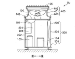
- 1 is a partially cutaway front view of the outdoor unit Ou
- FIG. 2 is a longitudinal sectional view thereof
- FIG. 3 is an exploded plan view thereof
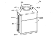
- FIG. 4 is a perspective view thereof.
- the outdoor unit Ou includes a main housing 300 formed in a substantially rectangular parallelepiped shape, and an upper cover 400 made of resin that covers the upper surface of the main housing 300.
- a motor support plate 102 is provided in a beam shape on the top of the main housing 300 in the front-rear direction. Further, a fan motor 101 is attached to the motor support plate 102, and a propeller fan 100 made of resin is coupled to a rotation shaft of the fan motor 101. The propeller fan 100 discharges the air inside the main housing 300 upward.
- the upper surface cover 400 has a fan peripheral portion 401 disposed so as to surround the propeller fan 100 and a top plate portion 403 formed in a substantially flat plate shape.
- a step portion 402 whose radius is expanded in a stepwise manner toward the upper side is formed, and in the air outlet on the further downstream side, metal is used to prevent intrusion of foreign matter and fingers.
- a fan guard 105 which is a net is attached. The fan guard 105 is detachable for maintenance.
- the portion obtained by combining the fan peripheral portion 401 and the step portion 402 described above is referred to as "bell mouth".
- a heat exchanger 200 having a substantially U-shaped planar view is mounted below the motor support plate 102 from the back surface 304 to the rear of the side surface 301 of the main housing 300.
- an electric component box 201 for housing various electric components is mounted on the top of the front surface 302 of the main housing 300.
- an electric component box 201 for housing various electric components is mounted on the top of the front surface 302 of the main housing 300.
- refrigeration cycle parts such as the compressor 103 and the accumulator 104 are mounted.
- FIG. 3 is an exploded plan view in which the outdoor unit Ou is disassembled into a main housing 300, an upper surface cover 400, and a fan guard 105.
- the main housing 300 when the propeller fan 100 rotates, outside air is drawn from the side surface 301 and the back surface 304 via the heat exchanger 200. During the heating operation, the outside air is cooled when passing through the heat exchanger 200, and discharged toward the upper side of the outdoor unit Ou.
- the fan guard 105 is formed by forming a metal wire in a net shape
- the fan guard fixing hole 106 b is formed by curving the metal wire in an annular shape at the four points.
- FIG. 4 is a perspective view of the outdoor unit Ou with the fan guard 105 removed.
- the fan guard fixing boss 106 a is formed in a substantially cylindrical shape having an axis in the vertical direction.
- the step portion 402 includes a plurality of annular portions 404 and a plurality of cylindrical portions 406 joined alternately.
- the annular portion 404 is formed in a substantially annular plate shape.
- the cylindrical portion 406 is formed in a substantially cylindrical shape.
- Each annular portion 404 is joined to the lower cylindrical portion 406 at its inner circumferential portion and is joined to the upper cylindrical portion 406 at its outer circumferential portion.
- the step portion 402 has a generally frusto-conical (tapered) shape in which the radius gradually increases toward the top as a whole.
- the cylindrical portion 406 is formed substantially in the vertical direction, but the annular portion 404 is inclined inward with respect to the horizontal surface by an angle ⁇ at which attached rain water flows down. This is to prevent rainwater from collecting in the annular portion 404.
- the inclination angle of the annular portion 404 is an angle ⁇ to the extent that rain water flows down, and the inclination angle of the cylindrical portion 406 is about 90 °.
- the inclination angle ⁇ of the annular portion 404 is desirably 1 ° or more (slope 1.75%) or more.
- the installation surface of the outdoor unit Ou is not always a horizontal surface, the assembly tolerance of the top cover 400 itself, the component tolerance, the deformation, and the like, it is more desirable to set the inclination angle ⁇ to 5 ° or more.
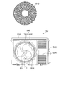
- FIG. 6 is a front view of the outdoor unit Ou.
- the outdoor unit Ou is referred to as a side flow type, and is widely used for separate-type air conditioners for home use or small-scale stores.
- a casing 500 of the outdoor unit Ou is formed in a substantially rectangular parallelepiped shape, and a compressor 504, a heat exchanger 506, and the like are disposed therein.
- the heat exchanger 506 is formed in a substantially U-shape over the rear surface and the rear surfaces of both side surfaces of the housing 500.
- a fan motor 501 is attached to the housing 500, and a propeller fan 502 made of resin is coupled to a rotation shaft of the fan motor 501.
- the propeller fan 502 discharges the air inside the housing 500 forward.
- the bell mouth 550 is made of resin, and is connected to the fan peripheral portion 551 disposed so as to surround the propeller fan 502 and the outlet side of the fan peripheral portion 551, and the step is such that the radius thereof is expanded stepwise toward the front. And a portion 552.
- a fan guard 510 which is a resin net, is mounted in front of the blowout opening of the bell mouth 550 in front of the blowout opening of the bell mouth 550 in front of the blowout opening of the bell mouth 550 in front of the blowout opening of the bell mouth 550 in front of the blowout opening of the bell mouth 550.
- the fan guard 510 is detachable for maintenance, and FIG. 6 shows the fan guard 510 removed.
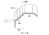
- FIG. 7 is a cross-sectional view taken along line II in FIG.
- the stepped portion 552 includes a plurality of annular portions 556 and a plurality of cylindrical portions 554 joined alternately.
- the annular portion 556 is formed in a substantially annular plate shape.
- the cylindrical portion 554 is formed in a substantially cylindrical shape.
- the annular portion 556 is joined to the rear cylindrical portion 554 at its inner peripheral portion, and is joined to the front cylindrical portion 554 at its outer peripheral portion.
- the step portion 552 has a generally frusto-conical (tapered) shape in which the radius gradually widens toward the front as a whole.
- the annular portion 556 is formed substantially along the vertical direction, but the cylindrical portion 554 is inclined outward at an angle ⁇ with respect to the horizontal surface. This is to prevent rainwater from collecting in the cylindrical portion 554, as described for the annular portion 404 (see FIG. 5) of the first embodiment. Therefore, the angle ⁇ is an angle at which rain water flows down, specifically, preferably 1 ° or more, and more preferably 5 ° or more.
- the inclination angle of the cylindrical portion 554 is the angle ⁇ at which rain water flows down, and the inclination angle of the annular portion 556 is about 90 °.
- an outdoor unit of an air conditioner according to a third embodiment of the present invention will be described.
- the overall configuration of the outdoor unit of the present embodiment is the same as that of the first embodiment (FIGS. 1 to 4).
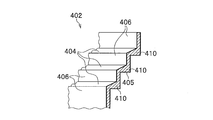
- the shape of the step portion 402 of the upper surface cover 400 is different from that of the first embodiment (FIG. 5). Therefore, the configuration of the step portion 402 in the present embodiment will be described with reference to FIG.
- the step portion 402 has a plurality of annular portions 404 and a plurality of cylindrical portions 406 joined alternately.
- the shape of the cylindrical portion 406 and the shape of the inner surface (upper surface) of the annular portion 404 are also similar to those of the first embodiment (FIG. 5).
- the outer surface 405 (lower surface) of the annular portion 404 is formed to be horizontal.
- the outer surface 405 of the annular portion 404 intersects the outer surface of the cylindrical portion 406 substantially at right angles, and the outer edge portion 410 of the annular portion 404 is thicker than the other portions of the annular portion 404.
- the outer surface of the stepped portion 402 is not particularly required to prevent the accumulation of rain water, and therefore no problem occurs even if the outer surface 405 of the annular portion 404 is horizontal.
- the strength of the step portion 402 can be improved.
- a cylindrical member such as the cylindrical portion 406 is easily deformed in an elliptical shape, and when the cylindrical portion 406 is deformed, vibration is likely to occur due to turbulent air flow.
- the roundness of the cylindrical portion 406 is improved by improving the strength of the annular portion 404. Vibration can be reduced by this.
- resin becomes easy to flow in the thick outer edge part 410, and a moldability also improves.
- an outdoor unit of an air conditioner according to a fourth embodiment of the present invention will be described.
- the overall configuration of the outdoor unit of the present embodiment is the same as that of the first embodiment (FIGS. 1 to 4).
- the shape of the step portion 402 of the upper surface cover 400 is different from that of the first embodiment (FIG. 5). Therefore, the configuration of the step portion 402 in the present embodiment will be described with reference to the cross-sectional view shown in FIG.
- the step portion 402 has a plurality of annular portions 404 and a plurality of cylindrical portions 406 joined alternately.
- the shape of the cylindrical portion 406 and the shape of the annular portion 404 are also substantially the same as those of the first embodiment (FIG. 5).
- one of the features is that the cross-sectional shape of the joint portion 407 (protruding portion) between the annular portion 404 and the cylindrical portion 406 is formed in an arc shape. If the bonding portion 407 is in the form of an edge, water droplets attached to the annular portion 404 will stay near the bonding portion 407 by surface tension and will not easily flow off. On the other hand, according to the present embodiment, since the cross-sectional shape of the joint portion 407 is formed in an arc shape, the water droplets attached to the annular portion 404 can be dropped smoothly.
- the radius of the arc shape of the joint portion 407 is preferably 1 mm or more, and more preferably 3 mm or more.
- the cross-sectional shape of the joint portion 407 may not necessarily be an "arc". That is, the cross-sectional shape may be a curved shape other than a circular arc, or may be linear (chamfering the bonding portion 407 with a flat surface).
- the top portion 409 of the uppermost cylindrical portion 406 has an arc shape with a radius of 1 mm or more.
- the inner side surface of the uppermost cylindrical portion 406 is substantially vertical, and the upper side inclined surface 408 is formed on the outer side surface so as to be inclined downward and outward from the top portion 409. According to this configuration, most of the water droplets dropped to the top portion 409 flow to the outer surface of the stepped portion 402 via the upper end inclined surface 408. As a result, it is possible to reduce the amount of water droplets flowing to the inner surface of the stepped portion 402. As described above, according to the present embodiment, in addition to the effects of the first embodiment, the water droplet can be more easily dropped.
- an outdoor unit of an air conditioner according to a fourth embodiment of the present invention will be described.
- the overall configuration of the outdoor unit of the present embodiment is the same as that of the fourth embodiment (FIGS. 1 to 3 and 9).
- the shape of the step portion 402 of the upper surface cover 400 is different from that of the fourth embodiment (FIG. 9). Therefore, the configuration of the step portion 402 in the present embodiment will be described with reference to the perspective view shown in FIG.
- the step portion 402 has a plurality of annular portions 404 and a plurality of cylindrical portions 406 joined alternately.
- the configuration of the joint portion 407 is an arc in cross section, and the upper end inclined surface 408 is formed on the outer surface of the uppermost cylindrical portion 406 as in the fourth embodiment (see FIG. It is the same as 9).
- the width W1 of the top ring portion 404 closest to the air outlet is wider than the width W2 of the second and subsequent ring portions 404. Therefore, the significance of setting the widths W1 and W2 of the annular portion 404 in this manner will be described.
- the fan guard 105 is mounted on the inside of the upper surface cover 400 so as to make it difficult for the user to see from the outside, because exposing the fan guard 105 gives the viewer an impressive impression. It is desirable to do.
- the fan guard fixing boss 106 a is provided inside the step portion 402, and the fan guard fixing hole 106 b is coupled to the fan guard fixing boss 106 a by the screw 107.
- the width W1 of the uppermost annular portion 404 is the second or subsequent annular ring. It is made wider than the width W2 of the part 404. Even if the widths W1 and W2 are equal, the widths W1 and W2 may be equal as long as the distance between the uppermost cylindrical portion 406 and the fan guard fixing boss 106a can be sufficiently secured.
- the widths W1 and W2 may be equal as long as the distance between the uppermost cylindrical portion 406 and the fan guard fixing boss 106a can be sufficiently secured.
- the outer surface of the step portion 402 is the same as the outer surface of the annular portion 404, as in the third embodiment (FIG. 8).
- the outer surface of the cylindrical portion 406 may intersect substantially at right angles.
- the uppermost cylindrical portion 406 is inclined at the upper end so as to be inclined outward and downward from the top portion 409 408 had been formed.
- the upper end inclined surface 408 may be formed to be inclined inward and downward from the top portion 409.
- the outdoor unit (Ou) of the air conditioner includes the propeller fan (100, 502) and the bellmouth (401, 402) disposed around the propeller fan (100, 502).
- the bell mouth (401, 402, 550) has a stepped portion (402, 552) that expands in a step-like manner toward the blowing direction of the propeller fan (100, 502),
- Each portion of the inner surface of the step portion (402, 552) is characterized in that it has an inclination angle (angle of ⁇ or more) through which the attached water droplets flow with respect to the horizontal surface.
- the thickness of the outer edge portion (410) of the stepped portion (402, 552) that protrudes outward is the same as that of the other portion. It is also characterized by having thickened. Thereby, while being able to suppress a vibration, a moldability can be improved.
- the bell mouth (401, 402) has an outlet opening upward, and the inclination angle ( ⁇ )
- a plurality of annular portions (404) having a substantially annular plate shape and a plurality of cylindrical portions (406) joined to the annular portions (404), and a plurality of the annular portions (404) And the width (W1) of the annular portion (404) at the top of the stages is wider than the width (W2) of the other annular portions (404), and the fan guard (105 And a fan guard fixing portion (106a) provided on the uppermost ring portion (404) and fixing the fan guard (105) to the step portion (402). Accordingly, it is possible to realize an outdoor unit of an air conditioner in which the upper surface cover 400 is not easily broken and which is also excellent in design.
- the bell mouth (401, 402) is a protrusion (see FIG. .
- the projection (407) is formed in a curved surface or chamfered in a planar shape.
- an upper end inclined surface (408) inclined toward the inner surface or the outer surface of the stepped portion (402) is formed at the upper end portion of the uppermost cylindrical portion (406).
- Ou outdoor unit 100 Propeller fan 105 Fan guard 106a Fan guard fixing boss (fan guard fixing part) 106b Fan Guard Fixing Hole 401 Fan around (Bellmouth) 402 Level difference (Bellmouth) 403 top plate portion 404 ring portion 406 cylindrical portion 407 joint portion (protruding portion) 408 top inclined surface 409 top portion 410 outer edge portion 500 casing 502 propeller fan 504 compressor 506 heat exchanger 510 fan guard 550 bell mouth 551 fan peripheral portion 552 step portion 554 cylindrical portion 556 annular portion
Landscapes
- Engineering & Computer Science (AREA)
- Chemical & Material Sciences (AREA)
- Combustion & Propulsion (AREA)
- Mechanical Engineering (AREA)
- General Engineering & Computer Science (AREA)
- Other Air-Conditioning Systems (AREA)
- Structures Of Non-Positive Displacement Pumps (AREA)
Abstract
空気調和機の室外機において、雨水の凍結等による破損を防止する。そのため、プロペラファンと、プロペラファンの周囲に配置されたベルマウスと、を備え、ベルマウスは、プロペラファンの吹出方向に向かって階段状に拡大する段差部(402)を有する。段差部(402)の内面の各部は、水平面に対して、付着した水滴が流れ落ちる傾斜角度(θ以上の角度)を有する。より具体的には、段差部(402)は、上方向に向かって開口する吹出口を有し、傾斜角度(θ)を有する略円環板状の複数の円環部(404)と、これら円環部(404)に接合された複数の円筒部(406)とを有する。
Description
本発明は、空気調和機の室外機および送風機に関する。
空気調和機の室外機には、プロペラファンによる風の流通路を囲むようにベルマウスが備えられる。その一例として、下記特許文献1の段落0015には、「吹出開口部5はベルマウス2の下流側(吹出側)において、空気を吹き出すために開口している部分である。吹出開口部5についても、プロペラファン1の回転軸と吹出開口部5の終端部分との間の距離(開口部分の径)が、回転軸と直管部4の面との間の距離(直管部4の径)よりも長い。そして、直管部4の吹出側終端(吹出開口部5吸込側終端)から吹出開口部5吹出側終端にいたる内壁面が拡がりを有する斜面となっており、断面形状がテーパ状(ラッパ状)になるように形成している。このテーパ状の部分を斜め部5aとする。ここで、本実施の形態のベルマウス2は直管部4を有しているが、斜め部5aとR部3aとにより内壁面を形成するようにしてもよい。」と記載されている。
上記特許文献1においては、ベルマウスの吹出開口部について「断面形状がテーパ状(ラッパ状)」と記載されている。これに対して、ベルマウスの吹出開口部の断面形状を階段状にすることが本件出願時に未公開の特願2015-053500号に提案されている。この出願によると、当該部分の断面形状を階段状にすると、ベルマウスの強度や真円度等の精度を向上させることができ、プロペラファンの効率を高めるとともに騒音を低減できるということである。
しかし、プロペラファンの下流側に段差部を設けると、雨天時には平坦部分に雨水が溜まりやすくなる。特に、気温が0℃付近の雨天時に暖房運転を行うと、暖房運転時には、吹出温度は外気よりも数℃程度低下するため、気温が0℃付近であれば、吹出温度は氷点下になる。すると、段差部に溜まった雨水が早期に凍結し、降雨が続くとさらに氷が成長してゆく。そして、成長した氷塊が回転中のプロペラファンと接触すると、プロペラファンが破損することがある。
この発明は上述した事情に鑑みてなされたものであり、破損を防止できる空気調和機の室外機および送風機を提供することを目的とする。
この発明は上述した事情に鑑みてなされたものであり、破損を防止できる空気調和機の室外機および送風機を提供することを目的とする。
上記課題を解決するため本発明による空気調和機の室外機にあっては、プロペラファンと、前記プロペラファンの周囲に配置されたベルマウスと、を備え、前記ベルマウスは、前記プロペラファンの吹出方向に向かって階段状に拡大する段差部を有し、前記段差部の内面の各部は、水平面に対して、付着した水滴が流れ落ちる傾斜角度を有することを特徴とする。
本発明によれば、空気調和機の室外機および送風機の破損を防止できる。
[第1実施形態]
〈全体構成〉
まず、図1~図4を参照し、本発明の第1実施形態による空気調和機の室外機Ouの構成を説明する。
この室外機Ou(送風機)は、トップフロータイプと呼ばれるものであり、中小規模の建築物におけるいわゆるマルチ型空気調和機に多用されている。図1は室外機Ouの一部切欠正面図、図2はその縦断面図、図3はその分解平面図、図4はその斜視図である。
図1において、室外機Ouは、略直方体状に形成された主筐体300と、主筐体300の上面を覆う樹脂製の上面カバー400とを有している。主筐体300の上部には、前後方向に渡ってモータ支持板102が梁状に設けられている。また、モータ支持板102には、ファンモータ101が装着されており、ファンモータ101の回転軸には、樹脂製のプロペラファン100が結合されている。プロペラファン100は、主筐体300の内部の空気を上方に向かって排出する。
〈全体構成〉
まず、図1~図4を参照し、本発明の第1実施形態による空気調和機の室外機Ouの構成を説明する。
この室外機Ou(送風機)は、トップフロータイプと呼ばれるものであり、中小規模の建築物におけるいわゆるマルチ型空気調和機に多用されている。図1は室外機Ouの一部切欠正面図、図2はその縦断面図、図3はその分解平面図、図4はその斜視図である。
図1において、室外機Ouは、略直方体状に形成された主筐体300と、主筐体300の上面を覆う樹脂製の上面カバー400とを有している。主筐体300の上部には、前後方向に渡ってモータ支持板102が梁状に設けられている。また、モータ支持板102には、ファンモータ101が装着されており、ファンモータ101の回転軸には、樹脂製のプロペラファン100が結合されている。プロペラファン100は、主筐体300の内部の空気を上方に向かって排出する。
上面カバー400は、プロペラファン100を取り囲むように配置されたファン周辺部401と、略平板状に形成された天板部403とを有している。ファン周辺部401の吹出口側には、その半径が上に向かって階段状に拡大する段差部402が形成され、さらに下流側の吹出口には、異物や指等の侵入を防ぐために、金属網であるファンガード105が装着されている。ファンガード105は、メンテナンスのために脱着可能になっている。上述したファン周辺部401および段差部402を合せた部分を「ベルマウス」と呼ぶ。
次に、図2において、モータ支持板102の下方には、主筐体300の背面304から側面301の後部に渡って、平面視が略U字状である熱交換器200が装着されている。また、主筐体300の前面302の上部には、各種電気部品を収納する電気部品箱201が装着されている。また、主筐体300の底面に設けられた底板303には、圧縮機103やアキュムレータ104等の冷凍サイクル部品が搭載されている。
図3は、室外機Ouを、主筐体300と、上面カバー400と、ファンガード105とに分解した状態における分解平面図である。主筐体300において、プロペラファン100が回転すると、側面301、背面304から熱交換器200を介して外気が吸い込まれる。暖房運転時においては、外気は熱交換器200を通過する際に冷却され、室外機Ouの上方に向かって放出される。また、ファンガード105は、金属線を網状に形成したものであるが、その4箇所において、金属線を環状に湾曲させてファンガード固定穴106bが形成されている。
また、上面カバー400の段差部402には、ファンガード固定穴106bに対向する箇所にファンガード固定ボス106a(ファンガード固定部)が形成されている。ファンガード固定ボス106aとファンガード固定穴106bとは、図示せぬネジによって着脱可能な状態で固定される。
次に、図4は、ファンガード105を除いた状態の室外機Ouの斜視図である。図4において、ファンガード固定ボス106aは、上下方向の軸を有する略円柱状に形成されている。
次に、図4は、ファンガード105を除いた状態の室外機Ouの斜視図である。図4において、ファンガード固定ボス106aは、上下方向の軸を有する略円柱状に形成されている。
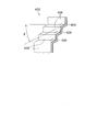
次に、図5に示す断面図を参照し、段差部402の詳細形状を説明する。
段差部402は、交互に接合された複数の円環部404と、複数の円筒部406とを有している。円環部404は、略円環の板状に形成されている。また、円筒部406は、略円筒状に形成されている。各円環部404は、その内周部において下方の円筒部406と接合されるとともに、その外周部において上方の円筒部406と接合されている。これにより、段差部402は、全体として、上に向かうほど段階的に半径が広がる、略切頭円錐状(テーパー状)の形状を有する。
段差部402は、交互に接合された複数の円環部404と、複数の円筒部406とを有している。円環部404は、略円環の板状に形成されている。また、円筒部406は、略円筒状に形成されている。各円環部404は、その内周部において下方の円筒部406と接合されるとともに、その外周部において上方の円筒部406と接合されている。これにより、段差部402は、全体として、上に向かうほど段階的に半径が広がる、略切頭円錐状(テーパー状)の形状を有する。
ここで、円筒部406は、ほぼ鉛直方向に沿って形成されるが、円環部404は、水平面に対して、付着した雨水が流れ落ちる程度の角度θだけ内側に向かって傾斜している。これは、円環部404に雨水が溜まることを防止するためである。上述したように、気温が0℃付近の雨天時に暖房運転を行うと、プロペラファン100の吹出温度は氷点下になるため、雨水が凍結しやすくなる。本実施形態においては、円環部404の傾斜角度は、雨水が流れ落ちる程度の角度θであり、円筒部406の傾斜角度は約90°であるから、段差部402の内面の各部は、全体に渡って、付着した水滴が流れ落ちる傾斜角度(θ以上の角度)を有する。これにより、段差部402の内壁面に沿って雨水を速やかに下方に落下させることができ、成長した氷塊によってプロペラファン100が損傷するような事態を未然に防止することができる。
ここで、一般的に1~2%程度の勾配があれば水滴は流れ落ちるとされるため、円環部404の傾斜角度θは1°以上(勾配1.75%)以上にすることが望ましい。但し、室外機Ouの据付面が必ずしも水平面にならないことや、上面カバー400自体の組立公差、部品公差、変形等を考慮すると、傾斜角度θを5°以上にすることが、より望ましい。
[第2実施形態]
次に、図6を参照し、本発明の第2実施形態による空気調和機の室外機Ouの構成を説明する。なお、図6は室外機Ouの正面図である。
この室外機Ouは、サイドフロータイプと呼ばれるものであり、家庭用または小規模店舗用のセパレート型空気調和機に多用されている。
次に、図6を参照し、本発明の第2実施形態による空気調和機の室外機Ouの構成を説明する。なお、図6は室外機Ouの正面図である。
この室外機Ouは、サイドフロータイプと呼ばれるものであり、家庭用または小規模店舗用のセパレート型空気調和機に多用されている。
図6において、室外機Ouの筐体500は、略直方体状に形成され、その内部には圧縮機504、熱交換器506等が配置されている。熱交換器506は、筐体500の後面および両側面後部に渡って、略U字状に形成されている。また、筐体500には、ファンモータ501が装着されており、ファンモータ501の回転軸には、樹脂製のプロペラファン502が結合されている。プロペラファン502は、筐体500の内部の空気を前方に向かって排出する。
ベルマウス550は樹脂によって形成され、プロペラファン502を取り囲むように配置されたファン周辺部551と、ファン周辺部551の吹出口側に結合され、その半径が前方に向かって階段状に拡大する段差部552とを有している。ベルマウス550の吹出口の前方は、異物や指等の侵入を防ぐために、樹脂製網であるファンガード510が装着される。ファンガード510は、メンテナンスのために脱着可能になっており、図6は、ファンガード510を取り外した状態を示している。
図7は、図6におけるI-I断面図である。段差部552は、交互に接合された複数の円環部556と、複数の円筒部554とを有している。円環部556は、略円環の板状に形成されている。また、円筒部554は、略円筒状に形成されている。円環部556は、その内周部において後方の円筒部554と接合されるとともに、その外周部において前方の円筒部554と接合されている。これにより、段差部552は、全体として、前方に向かうほど段階的に半径が広がる、略切頭円錐状(テーパー状)の形状を有する。
ここで、円環部556は、ほぼ鉛直方向に沿って形成されるが、円筒部554は、水平面に対して、角度θだけ外側に向かって傾斜している。これは、第1実施形態の円環部404(図5参照)について述べたことと同様に、円筒部554に雨水が溜まることを防止するためである。従って、角度θは雨水が流れ落ちる程度の角度であり、具体的には、1°以上にすることが望ましく、5°以上にすることがより望ましい。
本実施形態においては、円筒部554の傾斜角度は、雨水が流れ落ちる程度の角度θであり、円環部556の傾斜角度は約90°であるから、段差部552の内面の各部は、全体に渡って、付着した水滴が流れ落ちる傾斜角度(θ以上の角度)を有する。これにより、段差部552の内壁面に沿って雨水を速やかに下方に落下させることができ、サイドフロータイプの室外機Ouにおいても、成長した氷塊によってプロペラファン502が損傷するような事態を未然に防止することができる。
[第3実施形態]
次に、本発明の第3実施形態による空気調和機の室外機について説明する。
本実施形態の室外機の全体構成は、第1実施形態のもの(図1~図4)と同様である。但し、上面カバー400の段差部402の形状は、第1実施形態のもの(図5)とは異なっている。
そこで、図8を参照し、本実施形態における段差部402の構成を説明する。
本実施形態においても、段差部402は、交互に接合された複数の円環部404と、複数の円筒部406とを有している。そして、円筒部406の形状と、円環部404の内面(上面)の形状も、第1実施形態のもの(図5)と同様である。
次に、本発明の第3実施形態による空気調和機の室外機について説明する。
本実施形態の室外機の全体構成は、第1実施形態のもの(図1~図4)と同様である。但し、上面カバー400の段差部402の形状は、第1実施形態のもの(図5)とは異なっている。
そこで、図8を参照し、本実施形態における段差部402の構成を説明する。
本実施形態においても、段差部402は、交互に接合された複数の円環部404と、複数の円筒部406とを有している。そして、円筒部406の形状と、円環部404の内面(上面)の形状も、第1実施形態のもの(図5)と同様である。
但し、本実施形態においては、円環部404の外面405(下面)は水平になるように形成されている。これにより、円環部404の外面405は、円筒部406の外面と略直角に交わるようになり、円環部404の外縁部410は、円環部404の他の部分よりも肉厚になる。段差部402の外面については、雨水が溜まることを特に防止する必要性は無いため、円環部404の外面405を水平にしたとしても、特に支障は生じない。
一方、円環部404の外縁部410を肉厚にしたことにより、段差部402の強度を向上させることができる。円筒部406のような円筒状の部材は楕円状に変形しやすく、円筒部406が変形すると、乱気流によって振動が起こりやすくなる。本実施形態においては、円環部404の強度を向上させることにより、円筒部406の真円度を向上させる。これによって低振動化を実現することができる。また、段差部402を射出成形によって製造する場合は、肉厚の外縁部410において樹脂が流れやすくなり、成形性も向上する。
このように、本実施形態によれば、第1実施形態の効果に加えて、低振動化や成形性にも優れた、空気調和機の室外機を提供できるという効果を奏する。
このように、本実施形態によれば、第1実施形態の効果に加えて、低振動化や成形性にも優れた、空気調和機の室外機を提供できるという効果を奏する。
[第4実施形態]
次に、本発明の第4実施形態による空気調和機の室外機について説明する。
本実施形態の室外機の全体構成は、第1実施形態のもの(図1~図4)と同様である。但し、上面カバー400の段差部402の形状は、第1実施形態のもの(図5)とは異なっている。
そこで、図9に示す断面図を参照し、本実施形態における段差部402の構成を説明する。
本実施形態においても、段差部402は、交互に接合された複数の円環部404と、複数の円筒部406とを有している。そして、円筒部406の形状および円環部404の形状も、第1実施形態のもの(図5)とほぼ同様である。
次に、本発明の第4実施形態による空気調和機の室外機について説明する。
本実施形態の室外機の全体構成は、第1実施形態のもの(図1~図4)と同様である。但し、上面カバー400の段差部402の形状は、第1実施形態のもの(図5)とは異なっている。
そこで、図9に示す断面図を参照し、本実施形態における段差部402の構成を説明する。
本実施形態においても、段差部402は、交互に接合された複数の円環部404と、複数の円筒部406とを有している。そして、円筒部406の形状および円環部404の形状も、第1実施形態のもの(図5)とほぼ同様である。
但し、本実施形態においては、円環部404と円筒部406との接合部407(突出部)の断面形状を円弧状に形成した点が一つの特徴になっている。仮に、接合部407がエッジ状になっていると、円環部404に付着した水滴が、表面張力によって接合部407付近に留まり、流れ落ちにくくなる。これに対して、本実施形態によれば、接合部407の断面形状を円弧状に形成したので、円環部404に付着した水滴をスムーズに落下させることができる。なお、接合部407の円弧形状の半径は、1mm以上にすることが望ましく、3mm以上にすると、より望ましい。また、接合部407の断面形状は、必ずしも「円弧」でなくてもよい。すなわち、断面形状は、円弧以外の曲線形状であってもよく、直線状(接合部407を平面で面取りすること)であってもよい。
また、本実施形態においては、最上段の円筒部406の頂上部409は、その半径が1mm以上の円弧状になっている。そして、最上段の円筒部406の内側面はほぼ鉛直であり、外側面には、頂上部409から外側下方向に向かって傾斜する上端傾斜面408が形成されている。かかる構成によれば、頂上部409に落下した水滴は、その大部分が上端傾斜面408を介して段差部402の外面に流れる。これにより、段差部402の内面に流れ落ちる水滴を減少させることができる。
このように、本実施形態によれば、第1実施形態の効果に加えて、水滴がさらに流れ落ちやすくなるという効果を奏する。
このように、本実施形態によれば、第1実施形態の効果に加えて、水滴がさらに流れ落ちやすくなるという効果を奏する。
[第5実施形態]
次に、本発明の第4実施形態による空気調和機の室外機について説明する。
本実施形態の室外機の全体構成は、第4実施形態のもの(図1~図3、図9)と同様である。但し、上面カバー400の段差部402の形状は、第4実施形態のもの(図9)とは異なっている。そこで、図10に示す斜視図を参照し、本実施形態における段差部402の構成を説明する。
本実施形態においても、段差部402は、交互に接合された複数の円環部404と、複数の円筒部406とを有している。また、接合部407の構成は図9に示した通り断面が円弧状であり、最上段の円筒部406の外面に上端傾斜面408が形成されていることも、第4実施形態のもの(図9)と同様である。
次に、本発明の第4実施形態による空気調和機の室外機について説明する。
本実施形態の室外機の全体構成は、第4実施形態のもの(図1~図3、図9)と同様である。但し、上面カバー400の段差部402の形状は、第4実施形態のもの(図9)とは異なっている。そこで、図10に示す斜視図を参照し、本実施形態における段差部402の構成を説明する。
本実施形態においても、段差部402は、交互に接合された複数の円環部404と、複数の円筒部406とを有している。また、接合部407の構成は図9に示した通り断面が円弧状であり、最上段の円筒部406の外面に上端傾斜面408が形成されていることも、第4実施形態のもの(図9)と同様である。
但し、本実施形態においては、吹出口に最も近接する最上段の円環部404の幅W1は、2段目以降の円環部404の幅W2よりも広くなっている。そこで、円環部404の幅W1,W2をこのように設定した意義を説明する。ファンガード105として金属網を用いた場合、ファンガード105を露出させると観者に武骨な印象を与えるため、ファンガード105は、外部からは見えにくくなるように、上面カバー400の内側に装着することが望ましい。そのことを実現するために、ファンガード固定ボス106aは段差部402の内側に設け、ネジ107によってファンガード固定穴106bをファンガード固定ボス106aに結合する。
その際、最上段の円筒部406に直接的に接するようにファンガード固定ボス106aを設けることも考えられる。しかし、この場合、上面カバー400を樹脂によって一体整形すると、樹脂が固化する際、ファンガード固定ボス106aに接する円筒部406の外側面において、ヒケ(凹部)が発生する。ヒケが発生すると、上面カバー400の外観を損ねるとともに、このヒケの部分で上面カバー400が割れやすくなるという問題も生じる。そこで、本実施形態においては、最上段の円筒部406と、ファンガード固定ボス106aとの水平方向の距離をある程度離しておき、両者を略長方形の薄板部108によって接続している。
このように、最上段の円筒部406と、ファンガード固定ボス106aとの距離を確保するため、本実施形態においては、最上段の円環部404の幅W1は、2段目以降の円環部404の幅W2よりも広くしている。なお、幅W1,W2を等しくしても、最上段の円筒部406とファンガード固定ボス106aとの距離を充分に確保できるのであれば、幅W1,W2を等しくしてもよい。
このように、本実施形態によれば、第4実施形態の効果に加えて、上面カバー400が割れにくく、かつ意匠性にも優れた空気調和機の室外機を提供できるという効果を奏する。
このように、本実施形態によれば、第4実施形態の効果に加えて、上面カバー400が割れにくく、かつ意匠性にも優れた空気調和機の室外機を提供できるという効果を奏する。
[変形例]
本発明は上述した実施形態に限定されるものではなく、種々の変形が可能である。上述した実施形態は本発明を理解しやすく説明するために例示したものであり、必ずしも説明した全ての構成を備えるものに限定されるものではない。また、ある実施形態の構成の一部を他の実施形態の構成に置き換えることが可能であり、また、ある実施形態の構成に他の実施形態の構成を加えることも可能である。また、各実施形態の構成の一部について削除し、若しくは他の構成の追加・置換をすることが可能である。上記実施形態に対して可能な変形は、例えば以下のようなものである。
本発明は上述した実施形態に限定されるものではなく、種々の変形が可能である。上述した実施形態は本発明を理解しやすく説明するために例示したものであり、必ずしも説明した全ての構成を備えるものに限定されるものではない。また、ある実施形態の構成の一部を他の実施形態の構成に置き換えることが可能であり、また、ある実施形態の構成に他の実施形態の構成を加えることも可能である。また、各実施形態の構成の一部について削除し、若しくは他の構成の追加・置換をすることが可能である。上記実施形態に対して可能な変形は、例えば以下のようなものである。
(1)上述した各実施形態は、空気調和機の室外機Ouに本発明を適用した例を説明したが、本発明は、冷却水の温度を外気温に近づける冷却塔(クーリングタワー)、あるいは単に風を送風する送風機等、送風を行う様々な機器に適用することができる。
(2)上述した第4実施形態(図9)および第5実施形態(図10)において、段差部402の外面は、第3実施形態(図8)と同様に、円環部404の外面と円筒部406の外面とが略直角に交わるようにしてもよい。
(3)上述した第4実施形態(図9)および第5実施形態(図10)において、最上段の円筒部406には、頂上部409から外側下方向に向かって傾斜するように上端傾斜面408が形成されていた。しかし、上端傾斜面408は、頂上部409から内側下方向に向かって傾斜するように形成してもよい。
[構成・効果の総括]
以上のように、上記各実施形態による空気調和機の室外機(Ou)は、プロペラファン(100,502)と、前記プロペラファン(100,502)の周囲に配置されたベルマウス(401,402,550)と、を備え、前記ベルマウス(401,402,550)は、前記プロペラファン(100,502)の吹出方向に向かって階段状に拡大する段差部(402,552)を有し、前記段差部(402,552)の内面の各部は、水平面に対して、付着した水滴が流れ落ちる傾斜角度(θ以上の角度)を有することを特徴とする。
これにより、段差部(402,552)に付着した水滴が速やかに流れ落ちるので、水滴の氷結によって氷塊が成長するような事態を未然に防止でき、室外機(Ou)の破損を防止できる。
以上のように、上記各実施形態による空気調和機の室外機(Ou)は、プロペラファン(100,502)と、前記プロペラファン(100,502)の周囲に配置されたベルマウス(401,402,550)と、を備え、前記ベルマウス(401,402,550)は、前記プロペラファン(100,502)の吹出方向に向かって階段状に拡大する段差部(402,552)を有し、前記段差部(402,552)の内面の各部は、水平面に対して、付着した水滴が流れ落ちる傾斜角度(θ以上の角度)を有することを特徴とする。
これにより、段差部(402,552)に付着した水滴が速やかに流れ落ちるので、水滴の氷結によって氷塊が成長するような事態を未然に防止でき、室外機(Ou)の破損を防止できる。
また、第3実施形態(図8)による空気調和機の室外機(Ou)は、前記段差部(402,552)のうち外側に突出する外縁部(410)の肉厚を、他の部分よりも厚くしたことを特徴とする。
これにより、振動を抑制できるとともに、成形性を高めることができる。
これにより、振動を抑制できるとともに、成形性を高めることができる。
また、第5実施形態(図10)による空気調和機の室外機(Ou)は、前記ベルマウス(401,402)は、上方向に向かって開口する吹出口を有し、前記傾斜角度(θ)を有する略円環板状の複数の円環部(404)と、これら円環部(404)に接合された複数の円筒部(406)とを有し、複数の前記円環部(404)のうち最上段の前記円環部(404)の幅(W1)を他の前記円環部(404)の幅(W2)よりも広くしたものであり、前記吹出口を覆うファンガード(105)と、最上段の前記円環部(404)に設けられ、前記ファンガード(105)を前記段差部(402)に固定するファンガード固定部(106a)と、を有することを特徴とする。
これにより、上面カバー400が割れにくく、かつ意匠性にも優れた空気調和機の室外機を実現できる。
これにより、上面カバー400が割れにくく、かつ意匠性にも優れた空気調和機の室外機を実現できる。
また、第4実施形態(図9)および第5実施形態(図10)による空気調和機の室外機(Ou)は、前記ベルマウス(401,402)は、内側に向かって突出する突出部(407)を有するものであり、前記突出部(407)は、曲面状に形成され、または平面状に面取りされていることを特徴とする。
また、最上段の前記円筒部(406)の上端部に、前記段差部(402)の内面または外面に向かって傾斜する上端傾斜面(408)を形成した
ことも特徴とする。
これらの特徴により、さらに水滴が流れ落ちやすくすることができる。
また、最上段の前記円筒部(406)の上端部に、前記段差部(402)の内面または外面に向かって傾斜する上端傾斜面(408)を形成した
ことも特徴とする。
これらの特徴により、さらに水滴が流れ落ちやすくすることができる。
Ou 室外機(送風機)
100 プロペラファン
105 ファンガード
106a ファンガード固定ボス(ファンガード固定部)
106b ファンガード固定穴
401 ファン周辺部(ベルマウス)
402 段差部(ベルマウス)
403 天板部
404 円環部
406 円筒部
407 接合部(突出部)
408 上端傾斜面
409 頂上部
410 外縁部
500 筐体
502 プロペラファン
504 圧縮機
506 熱交換器
510 ファンガード
550 ベルマウス
551 ファン周辺部
552 段差部
554 円筒部
556 円環部
100 プロペラファン
105 ファンガード
106a ファンガード固定ボス(ファンガード固定部)
106b ファンガード固定穴
401 ファン周辺部(ベルマウス)
402 段差部(ベルマウス)
403 天板部
404 円環部
406 円筒部
407 接合部(突出部)
408 上端傾斜面
409 頂上部
410 外縁部
500 筐体
502 プロペラファン
504 圧縮機
506 熱交換器
510 ファンガード
550 ベルマウス
551 ファン周辺部
552 段差部
554 円筒部
556 円環部
Claims (7)
- プロペラファンと、
前記プロペラファンの周囲に配置されたベルマウスと、
を備え、
前記ベルマウスは、前記プロペラファンの吹出方向に向かって階段状に拡大する段差部を有し、
前記段差部の内面の各部は、水平面に対して、付着した水滴が流れ落ちる傾斜角度を有する
ことを特徴とする空気調和機の室外機。 - 前記傾斜角度は、水平面に対して5°以上であること
を特徴とする請求項1に記載の空気調和機の室外機。 - 前記段差部のうち外側に突出する外縁部の肉厚を、他の部分よりも厚くした
ことを特徴とする請求項2に記載の空気調和機の室外機。 - 前記ベルマウスは、上方向に向かって開口する吹出口を有し、前記傾斜角度を有する略円環板状の複数の円環部と、これら円環部に接合された複数の円筒部とを有し、複数の前記円環部のうち最上段の前記円環部の幅を他の前記円環部の幅よりも広くしたものであり、
前記吹出口を覆うファンガードと、
最上段の前記円環部に設けられ、前記ファンガードを前記段差部に固定するファンガード固定部と、
を有することを特徴とする請求項3に記載の空気調和機の室外機。 - 前記ベルマウスは、内側に向かって突出する突出部を有するものであり、
前記突出部は、曲面状に形成され、または平面状に面取りされている
ことを特徴とする請求項4に記載の空気調和機の室外機。 - 最上段の前記円筒部の上端部に、前記段差部の内面または外面に向かって傾斜する上端傾斜面を形成した
ことを特徴とする請求項5に記載の空気調和機の室外機。 - プロペラファンと、
前記プロペラファンの周囲に配置されたベルマウスと、
を備え、
前記ベルマウスは、前記プロペラファンの吹出方向に向かって階段状に拡大する段差部を有し、
前記段差部の内面の各部は、水平面に対して、付着した水滴が流れ落ちる傾斜角度を有する
ことを特徴とする送風機。
Priority Applications (1)
| Application Number | Priority Date | Filing Date | Title |
|---|---|---|---|
| CN201680078965.XA CN108474571B (zh) | 2016-01-18 | 2016-12-26 | 空调机的室外机及鼓风机 |
Applications Claiming Priority (2)
| Application Number | Priority Date | Filing Date | Title |
|---|---|---|---|
| JP2016006979A JP6731732B2 (ja) | 2016-01-18 | 2016-01-18 | 空気調和機の室外機および送風機 |
| JP2016-006979 | 2016-01-18 |
Publications (1)
| Publication Number | Publication Date |
|---|---|
| WO2017126296A1 true WO2017126296A1 (ja) | 2017-07-27 |
Family
ID=59361816
Family Applications (1)
| Application Number | Title | Priority Date | Filing Date |
|---|---|---|---|
| PCT/JP2016/088636 Ceased WO2017126296A1 (ja) | 2016-01-18 | 2016-12-26 | 空気調和機の室外機および送風機 |
Country Status (3)
| Country | Link |
|---|---|
| JP (1) | JP6731732B2 (ja) |
| CN (1) | CN108474571B (ja) |
| WO (1) | WO2017126296A1 (ja) |
Cited By (1)
| Publication number | Priority date | Publication date | Assignee | Title |
|---|---|---|---|---|
| US10684054B2 (en) * | 2017-05-22 | 2020-06-16 | Trane International Inc. | Tension support system for motorized fan |
Families Citing this family (1)
| Publication number | Priority date | Publication date | Assignee | Title |
|---|---|---|---|---|
| JP7258053B2 (ja) * | 2019-02-01 | 2023-04-14 | 三菱電機株式会社 | 底面パネル及び空気調和装置の室外機 |
Citations (4)
| Publication number | Priority date | Publication date | Assignee | Title |
|---|---|---|---|---|
| JPH0755202A (ja) * | 1993-08-20 | 1995-03-03 | Mitsubishi Electric Corp | 空気調和機の室外ユニット |
| US20060177306A1 (en) * | 2002-03-30 | 2006-08-10 | University Of Central Florida | High efficiency air conditioner condenser fan with performance enhancements |
| JP2008057480A (ja) * | 2006-09-01 | 2008-03-13 | Daikin Ind Ltd | シュラウド付プロペラファン |
| JP2008232536A (ja) * | 2007-03-20 | 2008-10-02 | Daikin Ind Ltd | 空気調和機用室外機 |
Family Cites Families (5)
| Publication number | Priority date | Publication date | Assignee | Title |
|---|---|---|---|---|
| KR20030035328A (ko) * | 2001-10-31 | 2003-05-09 | 삼성전자주식회사 | 공기조화기의 실외기 |
| JP2006242554A (ja) * | 2005-02-04 | 2006-09-14 | Matsushita Electric Ind Co Ltd | 空気調和機 |
| KR101234826B1 (ko) * | 2005-10-31 | 2013-02-20 | 삼성전자주식회사 | 공기조화기의 실외기 |
| KR102199376B1 (ko) * | 2013-07-12 | 2021-01-06 | 엘지전자 주식회사 | 원심 송풍기 및 이를 포함하는 공기 조화기 |
| CN203744394U (zh) * | 2014-02-25 | 2014-07-30 | 广东美的制冷设备有限公司 | 落地式空调室内机 |
-
2016
- 2016-01-18 JP JP2016006979A patent/JP6731732B2/ja active Active
- 2016-12-26 WO PCT/JP2016/088636 patent/WO2017126296A1/ja not_active Ceased
- 2016-12-26 CN CN201680078965.XA patent/CN108474571B/zh active Active
Patent Citations (4)
| Publication number | Priority date | Publication date | Assignee | Title |
|---|---|---|---|---|
| JPH0755202A (ja) * | 1993-08-20 | 1995-03-03 | Mitsubishi Electric Corp | 空気調和機の室外ユニット |
| US20060177306A1 (en) * | 2002-03-30 | 2006-08-10 | University Of Central Florida | High efficiency air conditioner condenser fan with performance enhancements |
| JP2008057480A (ja) * | 2006-09-01 | 2008-03-13 | Daikin Ind Ltd | シュラウド付プロペラファン |
| JP2008232536A (ja) * | 2007-03-20 | 2008-10-02 | Daikin Ind Ltd | 空気調和機用室外機 |
Cited By (1)
| Publication number | Priority date | Publication date | Assignee | Title |
|---|---|---|---|---|
| US10684054B2 (en) * | 2017-05-22 | 2020-06-16 | Trane International Inc. | Tension support system for motorized fan |
Also Published As
| Publication number | Publication date |
|---|---|
| JP6731732B2 (ja) | 2020-07-29 |
| CN108474571B (zh) | 2020-09-08 |
| CN108474571A (zh) | 2018-08-31 |
| JP2017129287A (ja) | 2017-07-27 |
Similar Documents
| Publication | Publication Date | Title |
|---|---|---|
| JP5289200B2 (ja) | 空気調和機用室外機 | |
| CN101631992B (zh) | 离心风扇、空调机 | |
| CN1333207C (zh) | 送风装置的风扇防护体 | |
| US8240997B2 (en) | Centrifugal impeller and centrifugal blower using the centrifugal impeller | |
| JP6223232B2 (ja) | 室外機 | |
| CN101990604A (zh) | 离心鼓风机 | |
| JP2016142431A (ja) | 空気調和機 | |
| JPH086717B2 (ja) | オリフィスシュラウド | |
| JP2017096587A (ja) | 天井埋込型空気調和機 | |
| JP5558378B2 (ja) | 空気調和機の室外ユニット | |
| CN1853046B (zh) | 吹风机和使用该吹风机的热交换器 | |
| CN101957048A (zh) | 排水盘 | |
| JP6731732B2 (ja) | 空気調和機の室外機および送風機 | |
| JP6283194B2 (ja) | 空気調和機の室外機 | |
| WO2004109118A1 (en) | Fan | |
| JP3882324B2 (ja) | 遠心ファン | |
| JP2017053301A (ja) | プロペラファン及び空気調和機の室外機 | |
| JP4760950B2 (ja) | 天井埋込形換気扇 | |
| JP2007205268A (ja) | 遠心ファン | |
| CN112013532A (zh) | 导风装置、具有其的空调室内机和空调系统 | |
| JP5530879B2 (ja) | 空気調和機の室内機 | |
| JP5812572B2 (ja) | 軸流送風機およびこの軸流送風機を用いた空気調和機の室外機 | |
| JP5494209B2 (ja) | 空気調和機 | |
| JP2018025357A (ja) | 室内機および空気調和機 | |
| CN220287619U (zh) | 顶盖组件、暖通设备室外机及暖通设备 |
Legal Events
| Date | Code | Title | Description |
|---|---|---|---|
| 121 | Ep: the epo has been informed by wipo that ep was designated in this application |
Ref document number: 16886534 Country of ref document: EP Kind code of ref document: A1 |
|
| NENP | Non-entry into the national phase |
Ref country code: DE |
|
| 122 | Ep: pct application non-entry in european phase |
Ref document number: 16886534 Country of ref document: EP Kind code of ref document: A1 |