WO2017126229A1 - 伝送路の劣化検出装置 - Google Patents
伝送路の劣化検出装置 Download PDFInfo
- Publication number
- WO2017126229A1 WO2017126229A1 PCT/JP2016/085181 JP2016085181W WO2017126229A1 WO 2017126229 A1 WO2017126229 A1 WO 2017126229A1 JP 2016085181 W JP2016085181 W JP 2016085181W WO 2017126229 A1 WO2017126229 A1 WO 2017126229A1
- Authority
- WO
- WIPO (PCT)
- Prior art keywords
- signal
- communication device
- transmission
- control circuit
- transmission path
- Prior art date
- Legal status (The legal status is an assumption and is not a legal conclusion. Google has not performed a legal analysis and makes no representation as to the accuracy of the status listed.)
- Ceased
Links
Images



Classifications
-
- H—ELECTRICITY
- H04—ELECTRIC COMMUNICATION TECHNIQUE
- H04B—TRANSMISSION
- H04B3/00—Line transmission systems
- H04B3/02—Details
- H04B3/46—Monitoring; Testing
- H04B3/493—Testing echo effects or singing
-
- G—PHYSICS
- G01—MEASURING; TESTING
- G01R—MEASURING ELECTRIC VARIABLES; MEASURING MAGNETIC VARIABLES
- G01R31/00—Arrangements for testing electric properties; Arrangements for locating electric faults; Arrangements for electrical testing characterised by what is being tested not provided for elsewhere
- G01R31/08—Locating faults in cables, transmission lines, or networks
- G01R31/11—Locating faults in cables, transmission lines, or networks using pulse reflection methods
-
- H—ELECTRICITY
- H04—ELECTRIC COMMUNICATION TECHNIQUE
- H04B—TRANSMISSION
- H04B3/00—Line transmission systems
- H04B3/02—Details
- H04B3/04—Control of transmission; Equalising
- H04B3/06—Control of transmission; Equalising by the transmitted signal
-
- H—ELECTRICITY
- H04—ELECTRIC COMMUNICATION TECHNIQUE
- H04B—TRANSMISSION
- H04B3/00—Line transmission systems
- H04B3/02—Details
- H04B3/20—Reducing echo effects or singing; Opening or closing transmitting path; Conditioning for transmission in one direction or the other
- H04B3/23—Reducing echo effects or singing; Opening or closing transmitting path; Conditioning for transmission in one direction or the other using a replica of transmitted signal in the time domain, e.g. echo cancellers
-
- H—ELECTRICITY
- H04—ELECTRIC COMMUNICATION TECHNIQUE
- H04M—TELEPHONIC COMMUNICATION
- H04M9/00—Arrangements for interconnection not involving centralised switching
- H04M9/08—Two-way loud-speaking telephone systems with means for conditioning the signal, e.g. for suppressing echoes for one or both directions of traffic
- H04M9/082—Two-way loud-speaking telephone systems with means for conditioning the signal, e.g. for suppressing echoes for one or both directions of traffic using echo cancellers
Definitions
- the present disclosure relates to a transmission line deterioration detection apparatus that detects a deteriorated state of a communication signal transmission line.
- An apparatus for detecting a failure such as a disconnection of a transmission path of a communication signal has been conventionally known, but there has been no configuration for detecting a state in which the transmission path has deteriorated before the transmission path fails.
- a method for detecting the deterioration of the transmission path for example, a method of counting the total usage time and predicting the deterioration based on the counted usage time can be considered. It was difficult to predict deterioration by time alone.
- Patent Document 1 describes a TDR (Time Domain Domain Reflectometry) method in which a pulse wave is applied to inspect deterioration.
- This TDR method is effective when inspecting a one-to-one communication transmission path.
- the sensitivity is insufficient, disconnection or connection failure of the transmission path can be detected, but deterioration cannot be detected.
- dedicated inspection devices such as a pulse generator, a probe, and an oscilloscope were required.
- a detection device that detects whether a response signal can be received is known.
- this apparatus when the communication apparatus of the communication partner is not an active communication apparatus, it is necessary to incorporate an inspection function into the communication apparatus of the communication partner, which causes a problem that the manufacturing cost increases.
- An object of the present disclosure is to provide a transmission line deterioration detection device that can detect deterioration of a transmission line before the transmission line breaks down, eliminates the need for a dedicated inspection device, and can suppress an increase in manufacturing cost. It is to provide.
- a first aspect of the present disclosure is a signal that is provided in a transmission line of a transmission system, a plurality of communication devices connected to the transmission line, and one communication device among the plurality of communication devices, and generates a pseudo communication signal.
- a degradation unit that detects degradation of the transmission path based on receiving the pseudo communication signal that is provided in the generation unit and one of the plurality of communication apparatuses and that has passed through the transmission path is provided. Is.
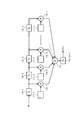
- FIG. 1 shows the first embodiment, and is an electrical configuration diagram showing an overall schematic configuration of a transmission system.
- FIG. 2 is a block diagram of an echo canceller.
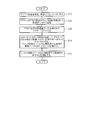
- FIG. 3 is a flowchart of the deterioration determination control.
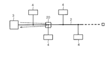
- FIG. 4 is a diagram for explaining a degradation place in the transmission system.
- FIG. 5 is a diagram illustrating an example of changes in the filter coefficients c (1) to c (n).
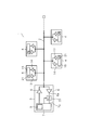
- FIG. 6 shows the second embodiment, and is an electrical configuration diagram showing an overall schematic configuration of the transmission system.
- FIG. 7 is a flowchart of the deterioration determination control.
- FIG. 1 shows the first embodiment, and is an electrical configuration diagram showing an overall schematic configuration of a transmission system.
- FIG. 2 is a block diagram of an echo canceller.
- FIG. 3 is a flowchart of the deterioration determination control.
- FIG. 4 is a diagram for explaining a degradation place in the transmission system.
- FIG. 5 is a diagram illustrating an example of changes
- FIG. 8 is a diagram for explaining a degradation place in the transmission system.
- FIG. 9 is a diagram illustrating an example of changes in the filter coefficients a (1) to a (n).
- FIG. 10 shows the third embodiment, and is an electrical configuration diagram showing an overall schematic configuration of the transmission system.
- FIG. 11 is a flowchart of the deterioration determination control.
- FIG. 12 shows a fourth embodiment and is a flowchart of deterioration determination control.
- the first embodiment will be described below with reference to FIGS. 1 to 5.
- the transmission system 1 is configured to be able to communicate by, for example, bus connection communication.
- a transmission path 2 that is a communication line and a plurality of communication devices 3 connected to the transmission path 2 4.
- the master communication device 3 has a transmission function and a reception function, and includes a driver circuit 5, a receiver circuit 6, a master control circuit 7, and an echo canceller 8.
- the driver circuit 5 receives a transmission data signal (that is, a digital signal) from the master control circuit 7, generates a transmission signal (that is, an analog pulse signal), and outputs the generated transmission signal to the transmission path 2.
- the driver circuit 5 includes a transmission-side analog circuit and a DAC (Digital Analog Converter) circuit.
- the receiver circuit 6 receives a voltage signal (that is, an analog pulse signal) from the transmission line 2, generates a reception signal (that is, a digital signal), and outputs the generated reception signal to the master control circuit 7.
- the receiver circuit 6 includes a reception-side analog circuit and an ADC (Analog Digital Converter) circuit.
- the master control circuit 7 has a function of transmitting a transmission data signal to the driver circuit 5 and receiving a reception signal from the receiver circuit 6.
- the master control circuit 7 has a function as a deterioration detection unit. When the reception signal received from the receiver circuit 6 is distorted, the master control circuit 7 has a function of correcting the distorted reception signal.
- the master control circuit 7 includes a signal generator 9 that generates, for example, a PRBS7 signal, which is a kind of pseudorandom signal, as a pseudo communication signal.
- the signal generator 9 has a function as a signal generator.
- the master control circuit 7 outputs the PRBS7 signal generated by the signal generator 9 to the transmission line 2 through the driver circuit 5 as a transmission signal.
- the echo canceller 8 has a function of canceling an echo of a transmission signal (that is, a PRBS7 signal), that is, a reflection signal from the transmission path 2.
- the echo canceller 8 has a function as a filter coefficient control circuit. The specific configuration and operation of the echo canceller 8 will be described later.
- the slave communication device 4 has a transmission function and a reception function, and includes a driver circuit 13, a receiver circuit 14, and a slave control circuit 15.
- the driver circuit 13 receives a transmission data signal (that is, a digital signal) from the slave control circuit 15 to generate a transmission signal (for example, a digital signal), and outputs the generated transmission signal to the transmission path 2.
- the receiver circuit 14 inputs a voltage signal (that is, an analog pulse signal) from the transmission line 2, digitizes the input signal using a simple determiner, and controls the slave as a received signal using the simplified digitized signal. Output to the circuit 15.
- the slave control circuit 15 has a function of transmitting a transmission data signal to the driver circuit 13 and receiving a reception signal from the receiver circuit 14. Unlike the master communication device 3, the slave communication device 4 does not include a processing circuit that corrects distortion of the received signal and a circuit that cancels echo of the transmission signal. That is, the slave communication device 4 is called a slave because it operates more passively than the master communication device 3.
- the echo canceller 8 automatically adjusts the filter coefficient so that when the transmission signal (that is, PRBS7 signal) is output from the master control circuit 7 to the transmission line 2 via the driver circuit 5, the reflection is reflected on the transmission line 2.
- the transmission signal that is, PRBS7 signal
- the signal returning to the master communication device 3, that is, the signal input to the reception terminal 7a of the master control circuit 7 can be controlled to be zero.
- the echo canceller 8 makes a copy of the echo by an internal circuit and subtracts it from the reflected signal, thereby controlling the signal input to the receiving terminal 7a of the master control circuit 7 to be zero.
- the formula for how to make a copy of Echo is:
- Echo (copy) c (1) x x (1) + c (2) x x (2) + ... + c (n) x x (n) (1)
- c (n) is a filter coefficient of the echo canceller
- x (n) is a PRBS7 signal as a transmission signal (that is, origin of echo) transmitted from the master communication device 3.
- Delay circuits 16-1 to 16-n and 16- (n + 1) are circuits that delay the input signal for a set time.
- the filter coefficient control circuits 17-1 to 17-n have a function of automatically adjusting the filter coefficients c (1) to c (n) so that the signal input to the reception terminal 7a of the master control circuit 7 becomes zero.
- the adjusted filter coefficients c (1) to c (n) are output.
- the multipliers 18-1 to 18-n calculate the multiplication part in the above equation (1).
- the adder 19 calculates the addition part in the above equation (1).
- As an algorithm for adjusting the filter coefficient for example, LMS (Least Mean Square) is preferably used, and other algorithms may be used.
- the specific value of n is preferably set according to the situation of the transmission path 2.
- the filter coefficients c (1) to c (n) of the echo canceller 8 are data corresponding to the magnitude of the signal that is reflected back (ie, echo).
- the data corresponds to the transmission characteristics. Therefore, the deterioration of the transmission path 2 can be determined by examining the change in the magnitude of each value of the filter coefficients c (1) to c (n).
- the master control circuit 7 acquires the filter coefficients c (1) to c (n) from the echo canceller 8 before deterioration of the transmission path 2 (for example, at the time of factory shipment or at the initial stage of operation), It is stored in an internal memory (for example, EEPROM or flash memory). Then, when the echo canceller 8 operates and controls so that the signal input to the reception terminal 7a of the master control circuit 7 becomes zero, the master control circuit 7 performs filter coefficients c (1) to c (1) to Acquire c (n) from the echo canceller 8 and compare the acquired filter coefficients c (1) to c (n) with the pre-degradation filter coefficients c (1) to c (n) stored in the memory.
- an internal memory for example, EEPROM or flash memory
- the process of operating the echo canceller 8 is mainly executed in a statup process until the main communication can be performed. Further, it is preferable that the processing for operating the echo canceller 8 is executed periodically (for example, once a day, once a week, etc.).
- the flowchart of FIG. 3 shows the content of the control for determining the deterioration of the transmission path 2 in the control of the master control circuit 7 of the master communication device 3.
- the master control circuit 7 transmits a control signal for stopping transmission and reception to all slave communication devices 4, and does not transmit or receive all slave communication devices 4. Enter mode.
- the process proceeds to step S20, and the master control circuit 7 transmits (ie, outputs) the PRBS7 signal to the transmission path 2 via the driver circuit 5.
- step S30 A part of the PRBS7 signal is reflected by the transmission line 2, the reflected wave (ie, echo signal) returns to the master communication device 3, and the returned reflected wave is received by the receiver circuit 6. Is received by the master control circuit 7.
- the master control circuit 7 controls the filter coefficients c (1) to c (n) of the filter coefficient control circuits 17-1 to 17-n of the echo canceller 8 to copy the echo signal. The echo is canceled by subtracting from the echo signal (ie, the reflected signal). In this case, control is performed so that the signal input to the receiving terminal 7a of the master control circuit 7 becomes zero. Since the filter coefficients c (1) to c (n) are characteristic data indicating the characteristics of the current transmission line 2, these filter coefficients c (1) to c (n) are stored in the master control circuit 7. Store in the memory.
- the filter coefficients c (1) to c (n) greatly changes in the increasing direction as shown in the table of FIG. Accordingly, when a large change as shown in the table of FIG. 5 is detected, the master control circuit 7 determines that the transmission path 2 has deteriorated. When the deterioration of the transmission path 2 is determined, the master control circuit 7 is configured to notify the user of a message indicating that the transmission path 2 has deteriorated. Thereby, the control shown in FIG. 3 is completed.
- the filter coefficients c (1) to c (n) greatly change is considered to be that impedance mismatching deteriorates due to deterioration of the transmission path 2 or disconnection.
- the control shown in FIG. 3 is configured to be executed in a statup process or periodically.
- the filter coefficient of the echo canceller 8 before deterioration (for example, at the time of shipment) is stored by the master control circuit 7, and when the echo canceller 8 operates thereafter, the echo canceller 8 filter coefficients are stored, and both filter coefficients are compared to determine whether or not the transmission path 2 has deteriorated.
- this configuration it is possible to detect deterioration of the transmission line 2 before the transmission line 2 breaks down, and it is possible to eliminate the need for a dedicated inspection device.
- since only the function of detecting the deterioration of the transmission line 2 is incorporated in the master control circuit 7 of the master communication device 3, an increase in manufacturing cost can be suppressed.
- the echo canceller 8 is periodically operated to update and store the filter coefficient, it is possible to grasp the deterioration process before the transmission line 2 is disconnected. Become. And according to the said structure, the disconnection of the transmission line 2, the connection failure of a connector, etc. are detectable by the change of the filter coefficient of the echo canceller 8. FIG.
- (Second Embodiment) 6 to 9 show a second embodiment.
- symbol is attached
- the signal generator 21 for generating the PRBS7 signal is provided in each of the slave control circuits 15 of the plurality of slave communication devices 4.
- an equalizer 22 is provided between the output terminal 6 a of the receiver circuit 6 and the input terminal 7 a of the master control circuit 7.
- the equalizer 22 has a function of correcting the distorted reception signal when the reception signal received by the receiver circuit 6 is distorted.
- the equalizer 22 has a function as a filter coefficient control circuit.
- a known PRBS7 signal is transmitted from any one slave communication device 4, and a distorted signal is received by the master communication device 3 through the transmission path 2, and this received signal is In the communication device 3, the equalizer 22 is entered via the receiver circuit 6. Since the equalizer 22 grasps the identity of the received PRBS7 signal, that is, the original waveform of the PRBS7 signal when transmitted from the slave communication device 4, the equalizer 22 adjusts the filter coefficient of the equalizer. Thus, it is possible to control so as to generate a PRBS7 signal having a substantially original waveform based on the received PRBS7 signal.
- the method for generating the PRBS7 signal is represented by the following equation.
- PRBS7 a (1) ⁇ i (1) + a (2) ⁇ i (2) + ... + a (n) ⁇ i (n) (2)
- a (n) is a filter coefficient of the equalizer
- i (n) is a received signal of the master communication device 3.
- the specific circuit of the equalizer 22 for calculating the above equation (2) that is, for generating the PRBS7 signal, has substantially the same circuit configuration as the specific circuit of the echo canceller 8 shown in FIG. It can be formed by a control circuit, a multiplier and an adder.
- the filter coefficients a (1) to a (n) of the equalizer 22 are automatically adjusted so that the signal input to the reception terminal 7a of the master control circuit 7 becomes the PRBS7 signal having the original waveform. 22 outputs the adjusted filter coefficients a (1) to a (n) to the master control circuit 7.
- the filter coefficients a (1) to a (n) of the equalizer 22 are data corresponding to the magnitude of the distortion of the signal entering the master communication device 3, and therefore the slave communication device. 4 and data corresponding to the transmission characteristics of the transmission path 2 between the master communication device 3. Therefore, the deterioration of the transmission path 2 between the slave communication device 4 and the master communication device 3 is determined by examining changes in the values of the filter coefficients a (1) to a (n). Can do.
- the master control circuit 7 uses the filter coefficient a () before the deterioration of the transmission path 2 between the slave communication device 4 and the master communication device 3 (for example, at the time of factory shipment or at the initial operation) 1) to a (n) are acquired from the equalizer 22 and stored in an internal memory (for example, an EEPROM or a flash memory).
- an internal memory for example, an EEPROM or a flash memory.
- the equalizer 22 compares the latest filter coefficients a (1) to a (n) stored in the memory with the pre-degradation filter coefficients a (1) to a (n) stored in the memory. Thus, it is possible to determine deterioration or failure of the transmission path 2 between the slave communication apparatus 4 and the master communication apparatus 3.
- the remaining slave communication devices 4 also transmit known PRBS7 signals to the transmission path 2, and transmit the transmission path 2 between the remaining slave communication devices 4 and the master communication device 3.
- the master communication device 3 receives the distorted signal, and the master communication device 3 adjusts the filter coefficient of the equalizer 22 in the master communication device 3 so that the waveform of the original waveform is substantially based on the received PRBS7 signal.
- Control for generating the PRBS7 signal is executed, and the filter coefficients a (1) to a (n) at that time are stored in the memory of the master control circuit 7.
- the master control circuit 7 then updates the latest filter coefficients a (1) to a (n) stored in the memory for each transmission path 2 between the remaining slave communication devices 4 and the master communication device 3.
- the deterioration of the transmission path 2 is determined by comparing with the pre-degradation filter coefficients a (1) to a (n) stored in the memory.
- the processing for operating the equalizer 22 is mainly executed in a stat-up process until the main communication is possible. Further, it is preferable that the process for operating the equalizer 22 is performed periodically (for example, once a day, once a week, etc.).
- the echo canceller 8 described in the first embodiment is provided inside the master communication device 3 so that echo cancellation processing is executed.
- the equalizer 22 according to the second embodiment is provided inside the master communication device 3 according to the first embodiment, and the signal generator according to the second embodiment. 21 is provided in the slave control circuit 15 of the slave communication device 4 of the first embodiment, and a process for correcting the distortion of the received signal is executed.
- step S110 the master control circuit 7 of the master communication device 3 is set to an operation mode in which the master communication device 3 is not transmitting and receiving. Subsequently, the process proceeds to step S120, and the master control circuit 7 transmits, for example, a control signal instructing to transmit the PRBS7 signal to the first (that is, the upper left in FIG. 6) slave communication device 4. The first slave communication device 4 transmits the PRBS7 signal to the transmission line 2 via the driver circuit 13.
- step S140 in the master communication device 3, the equalizer 22 controls the filter coefficients a (1) to a (n), and applies to the reception terminal 7a of the master control circuit 7 according to the equation (2).
- the input signal is adjusted to be the PRBS7 signal having the original waveform.
- the adjusted filter coefficients a (1) to a (n) become characteristic data indicating the characteristics of the transmission path 2 between the first slave communication device 4 and the master communication device 3 at the present time. From these, the filter coefficients a (1) to a (n) are stored in the memory in the master control circuit 7.
- step S150 the master control circuit 7 also applies the first slave communication device 4 to the remaining slave communication devices 4, for example, in order from the second (lower left in FIG. 6) slave communication device 4.
- Processing executed for the slave communication device 4, specifically, processing for transmitting the PRBS7 signal and operating the equalizer 22 to acquire the filter coefficients a (1) to a (n) and store them in the memory (ie, Steps S120 to S140) are executed.
- the filter coefficients a (1) to a (n) indicating the characteristics of each transmission line 2 between the second, third,... Slave communication device 4 and the master communication device 3 are obtained. And stored in the memory in the master control circuit 7.
- step S160 the master control circuit 7 determines the first, second,... Slave communication devices 4 at the present time based on the change over time of the filter coefficients a (1) to a (n).
- the deterioration or failure of each transmission line 2 between the communication device 3 and the master communication device 3 is determined. Specifically, for each transmission path 2 between the first, second,... Slave communication device 4 and the master communication device 3, before the deterioration stored in the memory, for example, at the time of shipment from the factory.
- the filter coefficients a (1) to a (n) with the latest filter coefficients a (1) to a (n) stored in the memory, the current first, second, ... slaves
- the deterioration of each transmission line 2 between the communication device 4 and the master communication device 3 is determined.
- the current slave of the fourth slave The coefficients a (1) and a (2) in the filter coefficients a (1) to a (n) indicating the characteristics of the transmission line 2 between the communication device 4 and the master communication device 3 are shown in the table of FIG. As shown in the figure, the direction of the increase greatly changes. Therefore, when a large change as shown in the table of FIG. 9 is detected, the master control circuit 7 determines that the transmission path 2 between the fourth slave communication device 4 and the master communication device 3 has deteriorated. It comes to judge.
- the master control circuit 7 When it is determined that the transmission path 2 has deteriorated, the master control circuit 7 is configured to notify the user of a message indicating that the transmission path 2 has deteriorated. In this case, the filter coefficients a (1) to a (n) indicating the characteristics of the transmission paths 2 between the slave communication devices 4 other than the fourth and the master communication device 3 are not significantly changed. Therefore, the master control circuit 7 does not determine that each transmission line 2 has deteriorated. Thereby, the control shown in FIG. 7 ends.
- the filter coefficients a (1) to a (n) largely change is considered to be that impedance mismatching deteriorates due to degradation of the transmission path 2, disconnection, or the like. Further, the control shown in FIG. 7 is configured to be executed in a statup process or periodically.
- the configuration of the second embodiment other than that described above is the same as the configuration of the first embodiment. Therefore, in the second embodiment, substantially the same operational effects as in the first embodiment can be obtained.
- (Third embodiment) 10 and 11 show a third embodiment.
- symbol is attached
- the communication unit 24 is provided in the master communication device 3 so that the master control circuit 7 can communicate with the management device 26 in the management center via the communication unit 24 and the communication network 25.
- the communication network 25 is composed of, for example, a mobile phone network or the Internet.
- the management device 26 is configured by a computer such as a server, for example.
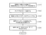
- FIG. 11 shows a flowchart of deterioration detection control of the third embodiment.
- the processing from step S110 to step S150 in FIG. 7 of the second embodiment is executed. Thereafter, the process proceeds to step S210 in FIG. 11, and the master control circuit 7 of the master communication device 3 executes the processes from step S110 to step S150 to update the filter updated periodically or in the startup process.
- Data of coefficients a (1) to a (n) is stored in an area for uploading to the management center in the internal memory. At this time, the update time data of the filter coefficients a (1) to a (n) is also stored in the area.
- step S220 the master control circuit 7 obtains the updated filter coefficients a (1) to a (n) and the execution time data at any time (for example, when step S210 is executed).
- the data is transmitted (that is, uploaded) to the management device 26 of the management center via the communication unit 24 and the communication network 25.
- step S230 the management device 26 in the management center receives the filter coefficients a (1) to a (n) and the execution time data transmitted from the master communication device 3, and receives the received filter coefficient a. (1) to a (n) and execution time data are stored in an internal memory (such as a hard disk). Furthermore, the management device 26 determines the status of the transmission path 2 based on the received filter coefficients a (1) to a (n) and the execution time, and a unique database for deterioration determination stored in the internal memory. That is, the degree of deterioration and failure are analyzed.
- step S240 the management device 26 can predict the replacement time of the parts according to the analysis result of the state of the transmission path 2, so that the user visits the store before the failure occurs.
- the management device 26 sends a message to the master communication device 3 via the communication network 25 to urge the user to visit the store for repair, thereby notifying the user. It is preferable to configure as described above.
- the transmission system 1 of this embodiment is mounted in a vehicle, for example, the user may visit the store instructed by the message in the vehicle.
- the configuration of the third embodiment other than that described above is the same as the configuration of the second embodiment. Therefore, in the third embodiment, substantially the same operational effects as in the second embodiment can be obtained.
- the filter coefficients a (1) to a (n) and the execution time data can be stored in a large-capacity memory of the management device 26, the filter coefficients a (1) to a (n) It is possible to periodically accumulate and store a large amount of soot and execution time data from the state before deterioration. Since the state of the transmission line 2 can be analyzed based on the large amount of stored data and a unique database for determining deterioration inside the management device 26, the state of deterioration of the transmission line 2 and the like can be more accurately determined. Analysis can be performed, and the detection accuracy of deterioration and the like can be increased.
- FIG. 12 shows a fourth embodiment.
- symbol is attached
- the fourth embodiment is configured to be applied to, for example, a transmission system mounted on a vehicle, and stores filter coefficients a (1) to a (n) and execution time data in the memory of the management device 26 of the management center. Instead, it is configured to be stored in a diagnostic memory mounted on the vehicle.
- FIG. 12 shows a flowchart of the degradation detection control of the fourth embodiment.
- the processing from step S110 to step S150 in FIG. 7 of the second embodiment is executed. Thereafter, the process proceeds to step S210 in FIG. 12, and the master control circuit 7 of the master communication device 3 executes the processes from step S110 to step S150 to update the filter updated periodically or in the startup process.
- Data of coefficients a (1) to a (n) is stored in an area for storing in a diagnosis memory in the internal memory.
- the update time data of the filter coefficients a (1) to a (n) is also stored in the area.
- step S320 the master control circuit 7 obtains the updated filter coefficients a (1) to a (n) and the execution time data at any time (for example, when step S210 is executed). It is stored (that is, transcribed) in a diagnostic memory mounted on the vehicle.
- step S330 when the user visits the vehicle by a vehicle inspection or the like, the store serviceman reads the filter coefficients a (1) to a (n) and the execution time stored in the vehicle memory. Data is read (i.e., downloaded) and stored in the memory of a store management device (e.g., a computer such as a server or terminal).
- a store management device e.g., a computer such as a server or terminal.
- step S340 the store management apparatus is based on the stored filter coefficients a (1) to a (n) and the execution time, and the original database for deterioration determination stored in the internal memory. Then, the state of the transmission path 2, that is, the degree of progress of deterioration, failure, etc. are analyzed.
- step S350 the store management device can predict the replacement time of the parts in accordance with the analysis result of the state of the transmission path 2, and therefore visits the user before the failure occurs.
- the management device is configured to display a message prompting to visit the store for repair on the display device or to notify the user by e-mail or the like when the time for parts replacement is approaching. Note that a clerk who has confirmed the message displayed on the management device may notify the user by telephone or the like.
- the configuration of the fourth embodiment other than that described above is the same as the configuration of the third embodiment. Therefore, in the fourth embodiment, substantially the same operational effects as in the third embodiment can be obtained.
- step S110 of FIG. 7 of FIG. 7 of FIG. 11 to step S150 might be performed before FIG.11 and FIG.12
- the processing from step S10 to step S40 of FIG. 3 of the first embodiment may be executed.
- filter coefficients c (1) to c (n) of the echo canceller 8 are used instead of the filter coefficients a (1) to a (n) of the equalizer 22. Also when comprised in this way, the effect similar to 3rd Embodiment and 4th Embodiment can be acquired.
- the PRBS7 signal is used as the pseudo communication signal.
- the present invention is not limited to this, and other signals may be used.
- the echo canceller 8 and the equalizer 22 are used as the filter coefficient control circuit.
- the present invention is not limited to this, and other circuits may be used.
Landscapes
- Engineering & Computer Science (AREA)
- Signal Processing (AREA)
- Computer Networks & Wireless Communication (AREA)
- Physics & Mathematics (AREA)
- General Physics & Mathematics (AREA)
- Cable Transmission Systems, Equalization Of Radio And Reduction Of Echo (AREA)
- Dc Digital Transmission (AREA)
- Maintenance And Management Of Digital Transmission (AREA)
- Testing Of Short-Circuits, Discontinuities, Leakage, Or Incorrect Line Connections (AREA)
- Tests Of Electronic Circuits (AREA)
- Telephone Function (AREA)
Abstract
伝送路の劣化検出装置は、伝送システムの伝送路(2)と、伝送路(2)に接続された複数の通信装置(3、4)と、複数の通信装置(3、4)の中の1つの通信装置(3、4)に設けられ、疑似通信信号を発生する信号発生部(9、21)と、複数の通信装置(3、4)の中の1つの通信装置(3、4)に設けられ、前記伝送路(2)を通った前記疑似通信信号を受信することに基づいて前記伝送路(2)の劣化を検出する劣化検出部(7)とを備えたものである。
Description
本出願は、2016年1月18日に出願された日本出願番号2016-7112号に基づくもので、ここにその記載内容を援用する。
本開示は、通信信号の伝送路の劣化した状態を検出する伝送路の劣化検出装置に関する。
通信信号の伝送路の例えば断線等の故障を検出する装置は、従来より、知られているが、伝送路が故障する前に、伝送路が劣化した状態を検出する構成はなかった。伝送路の劣化を検出する方法として、例えばトータルの使用時間をカウントし、カウントした使用時間に基づいて劣化を予測する方法が考えられるが、使用環境などの種々の要因が影響するため、上記使用時間だけでは劣化の予測は困難であった。
特許文献1には、パルス波を印加して劣化を検査するTDR(Time Domain Reflectometry)方式が記載されている。このTDR方式は、一対一の通信伝送路を検査する場合に有効であるが、感度が不足するため、伝送路の断線や接続不良は検出できるが、劣化は検出できなかった。また、パルス発生器、プローブ、オシロスコープ等の専用の検査装置が必要であった。
また、一対一の通信伝送路を検査する装置として、返答信号を受信できるかどうかを検出する検出装置が知られている。しかし、この装置の場合、通信相手の通信装置がアクティブな通信装置でないときには、通信相手の通信装置に検査機能を組み込む必要があるため、製造コストが高くなるという問題があった。
本開示の目的は、伝送路が故障する前に伝送路の劣化を検出することができ、また、専用の検査装置を不要にできると共に、製造コストの上昇を抑制できる伝送路の劣化検出装置を提供することにある。
本開示の第1の態様は、伝送システムの伝送路と、伝送路に接続された複数の通信装置と、複数の通信装置の中の1つの通信装置に設けられ、疑似通信信号を発生する信号発生部と、複数の通信装置の中の1つの通信装置に設けられ、前記伝送路を通った前記疑似通信信号を受信することに基づいて前記伝送路の劣化を検出する劣化検出部を備えたものである。
本開示についての上記目的およびその他の目的、特徴や利点は、添付の図面を参照しながら下記の詳細な記述により、より明確になる。その図面は、
図1は、第1実施形態を示すもので、伝送システムの全体概略構成を示す電気的構成図であり、
図2は、エコーキャンセラーのブロック図であり、
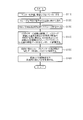
図3は、劣化判定制御のフローチャートであり、
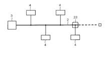
図4は、伝送システムにおける劣化場所を説明する図であり、
図5は、フィルタ係数c(1)~c(n)の変化の例を示す図であり、
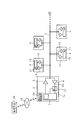
図6は、第2実施形態を示すもので、伝送システムの全体概略構成を示す電気的構成図であり、
図7は、劣化判定制御のフローチャートであり、
図8は、伝送システムにおける劣化場所を説明する図であり、
図9は、フィルタ係数a(1)~a(n)の変化の例を示す図であり、
図10は、第3実施形態を示すもので、伝送システムの全体概略構成を示す電気的構成図であり、
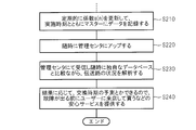
図11は、劣化判定制御のフローチャートであり、
図12は、第4実施形態を示すもので、劣化判定制御のフローチャートである。
(第1実施形態)
以下、第1実施形態について、図1ないし図5を参照して説明する。本実施形態の伝送システム1は、例えばバス接続通信で通信可能な構成であり、図1に示すように、通信線である伝送路2と、伝送路2に接続された複数の通信装置3、4とを備えて構成されている。
以下、第1実施形態について、図1ないし図5を参照して説明する。本実施形態の伝送システム1は、例えばバス接続通信で通信可能な構成であり、図1に示すように、通信線である伝送路2と、伝送路2に接続された複数の通信装置3、4とを備えて構成されている。
伝送路2は、例えばシングルエンド方式の伝送路で構成されている。尚、伝送路2を差動伝送方式の伝送路で構成しても良い。通信装置3は、マスターの通信装置である。通信装置4は、スレーブの通信装置であり、1個以上(例えば図1では4個)のスレーブの通信装置4が伝送路2に接続されている。
マスターの通信装置3は、送信機能及び受信機能を有しており、ドライバ回路5と、レシーバ回路6と、マスター用制御回路7と、エコーキャンセラー8とを備えている。ドライバ回路5は、マスター用制御回路7から送信用データ信号(即ち、デジタル信号)を入力し、送信信号(即ち、アナログのパルス信号)を生成し、生成した送信信号を伝送路2に出力する。ドライバ回路5は、送信側アナログ回路とDAC(Digital Analog Convertor)回路とを備えている。
レシーバ回路6は、伝送路2から電圧信号(即ち、アナログのパルス信号)を入力し、受信信号を生成し(即ち、デジタル信号)、生成した受信信号をマスター用制御回路7へ出力する。レシーバ回路6は、受信側アナログ回路とADC(Analog Digital Convertor)回路とを備えている。
マスター用制御回路7は、送信用データ信号をドライバ回路5に送信すると共に、レシーバ回路6から受信信号を受信する機能を有する。マスター用制御回路7は、劣化検出部としての機能を有する。マスター用制御回路7は、レシーバ回路6から受信した受信信号が歪んでいる場合、歪んだ受信信号を補正する機能を有する。
また、マスター用制御回路7は、疑似通信信号として疑似ランダム信号の一種である例えばPRBS7信号を発生する信号発生器9を備えている。信号発生器9は、信号発生部としての機能を有する。マスター用制御回路7は、信号発生器9で発生したPRBS7信号を送信信号としてドライバ回路5を介して伝送路2に出力する。
エコーキャンセラー8は、送信信号(即ち、PRBS7信号)のエコー、即ち、伝送路2からの反射信号をキャンセルする機能を有する。エコーキャンセラー8は、フィルタ係数制御回路としての機能を有する。尚、エコーキャンセラー8の具体的構成及び動作については、後述する。
また、スレーブの通信装置4は、送信機能及び受信機能を有しており、ドライバ回路13と、レシーバ回路14と、スレーブ用制御回路15とを備えている。ドライバ回路13は、スレーブ用制御回路15から送信用データ信号(即ち、デジタル信号)を入力して送信信号(例えばデジタル信号のまま)を生成し、生成した送信信号を伝送路2に出力する。レシーバ回路14は、伝送路2から電圧信号(即ち、アナログのパルス信号)を入力し、入力した信号を簡単な判定器を用いて簡易デジタル化し、簡易デジタル化した信号を受信信号としてスレーブ用制御回路15へ出力する。
スレーブ用制御回路15は、送信用データ信号をドライバ回路13に送信すると共に、レシーバ回路14から受信信号を受信する機能を有する。尚、スレーブの通信装置4は、マスターの通信装置3とは異なり、受信信号の歪を補正する処理回路や、送信信号のエコーをキャンセルする回路を備えていない。即ち、スレーブの通信装置4は、マスターの通信装置3に比べると、受動的に動作することから、スレーブと呼ばれる。
次に、エコーキャンセラー8の具体的構成及び動作について、図2ないし図5を参照して説明する。
エコーキャンセラー8は、フィルター係数を自動調整することにより、マスター用制御回路7から送信信号(即ち、PRBS7信号)がドライバ回路5を介して伝送路2に出力されたときに、伝送路2において反射してマスターの通信装置3に戻ってくる信号、即ち、マスター用制御回路7の受信端子7aに入力する信号がゼロとなるように制御することが可能なように構成されている。
エコーキャンセラー8は、フィルター係数を自動調整することにより、マスター用制御回路7から送信信号(即ち、PRBS7信号)がドライバ回路5を介して伝送路2に出力されたときに、伝送路2において反射してマスターの通信装置3に戻ってくる信号、即ち、マスター用制御回路7の受信端子7aに入力する信号がゼロとなるように制御することが可能なように構成されている。
具体的には、エコーキャンセラー8は、エコーのコピーを内部の回路で作って上記反射信号から引き算することにより、マスター用制御回路7の受信端子7aに入力する信号がゼロとなるように制御する。エコーのコピーの作り方を式で表すと、次の式となる。
Echo(copy)=c(1)×x(1)+c(2)×x(2)+・・・+c(n)×x(n) (1)
ここで、c(n)はエコーキャンセラーのフィルタ係数であり、x(n)はマスターの通信装置3から送信される送信信号(即ち、エコーの由来)としてのPRBS7信号である。
ここで、c(n)はエコーキャンセラーのフィルタ係数であり、x(n)はマスターの通信装置3から送信される送信信号(即ち、エコーの由来)としてのPRBS7信号である。
エコーキャンセラー8の具体的構成を、図2に示す。エコーキャンセラー8は、(n+1)個の遅延回路16-1~16-n、16-(n+1)と、n個のフィルタ係数制御回路17-1~17-nと、n個の乗算器18-1~18-nと、1個の加算器19とを備えている。
遅延回路16-1~16-n、16-(n+1)は、入力信号を設定時間遅延させる回路である。フィルタ係数制御回路17-1~17-nは、マスター用制御回路7の受信端子7aに入力する信号がゼロとなるようにフィルタ係数c(1)~c(n)を自動調整する機能を有し、調整したフィルタ係数c(1)~c(n)を出力する。乗算器18-1~18-nは、上記式(1)中の乗算部分を計算する。加算器19は、上記式(1)中の加算部分を計算する。尚、フィルタ係数の調整用のアルゴリズムとしては、例えばLMS(Least Mean Square)等を用いることが好ましく、他のアルゴリズムを用いても良い。また、nの具体値は、伝送路2の状況に応じて設定することが好ましい。
この構成においては、エコーキャンセラー8のフィルター係数c(1)~c(n)は、反射して戻ってくる信号(即ち、エコー)の大きさに対応したデータであることから、伝送路2の伝送特性に対応したデータとなる。従って、フィルター係数c(1)~c(n)の各値の大きさの変化を調べることにより、伝送路2の劣化を判定することができる。
本実施形態では、マスター用制御回路7は、伝送路2の劣化前(例えば工場出荷時または稼働初期時等)のフィルター係数c(1)~c(n)をエコーキャンセラー8から取得して、内部のメモリ(例えばEEPROMやフラッシュメモリ等)に記憶している。そして、マスター用制御回路7は、エコーキャンセラー8が動作してマスター用制御回路7の受信端子7aに入力する信号がゼロとなるように制御したときに、そのときのフィルター係数c(1)~c(n)をエコーキャンセラー8から取得し、取得したフィルター係数c(1)~c(n)と、メモリに記憶しておいた劣化前のフィルター係数c(1)~c(n)と比較することにより、伝送路2の劣化を判定するように構成されている。尚、上記エコーキャンセラー8を動作させる処理は、主に本通信できるまでのスタットアップ過程において実行される。また、上記エコーキャンセラー8を動作させる処理は、定期的(例えば1日1回、週1回等)に実行するように構成することが好ましい。
図3のフローチャートは、マスターの通信装置3のマスター用制御回路7の制御の中の伝送路2の劣化を判定する制御の内容を示す。まず、ステップS10においては、マスター用制御回路7は、送信及び受信を停止する制御信号を全てのスレーブの通信装置4へ送信し、全てのスレーブの通信装置4を送信及び受信をしていない運転モードにする。続いて、ステップS20へ進み、マスター用制御回路7は、PRBS7信号をドライバ回路5を介して伝送路2に送信(即ち、出力)する。
次いで、ステップS30へ進み、PRBS7信号は、その一部が伝送路2で反射され、反射波(即ち、エコー信号)がマスターの通信装置3へ戻ってきて、戻ってきた反射波をレシーバ回路6を介してマスター用制御回路7が受信する。そして、ステップS40へ進み、マスター用制御回路7は、エコーキャンセラー8のフィルタ係数制御回路17-1~17-nのフィルター係数c(1)~c(n)を制御して、エコー信号のコピーを作って上記エコー信号(即ち、反射信号)から引き算することによりエコーをキャンセルする。この場合、マスター用制御回路7の受信端子7aに入力する信号がゼロとなるように制御する。そして、フィルター係数c(1)~c(n)は、現時点の伝送路2の特性を示す特性データとなることから、これらフィルター係数c(1)~c(n)をマスター用制御回路7内のメモリに記憶する。
続いて、ステップS50へ進み、マスター用制御回路7は、フィルター係数c(1)~c(n)の経時変化に基づいて、即ち、メモリに記憶している劣化前例えば出荷時のフィルター係数c(1)~c(n)と、メモリに記憶した最新のフィルター係数c(1)~c(n)を比較することにより、伝送路2の劣化を判断する。
この場合、例えば、図4に示すように、2番目のスレーブの通信装置4と伝送路2とを接続するコネクタ20が劣化したとすると、フィルター係数c(1)~c(n)の中の係数c(1)が図5の表に示すように増大する方向に大きく変化する。従って、図5の表に示すような大きな変化を検出すると、マスター用制御回路7は伝送路2が劣化したと判定するようになっている。そして、伝送路2の劣化が判定されたときには、マスター用制御回路7は、伝送路2が劣化したことを示すメッセージ等をユーザに報知するように構成されている。これにより、図3に示す制御が終了する。
尚、上記したフィルター係数c(1)~c(n)が大きく変化する原因は、伝送路2の劣化、断線等によってインピーダンスの不整合が悪化するためであると考えられる。また、図3に示す制御は、スタットアップ過程において実行されたり、定期的に実行されたりするように構成されている。
このような構成の本実施形態においては、マスター用制御回路7によって劣化前(例えば出荷時)のエコーキャンセラー8のフィルター係数を記憶しておき、その後、エコーキャンセラー8が動作したときに、エコーキャンセラー8のフィルター係数を記憶し、両フィルター係数を比較することにより、伝送路2に劣化が発生したか否かを判定する。この構成によれば、伝送路2が故障する前に伝送路2の劣化を検出することができ、しかも、専用の検査装置を不要にできる。また、上記構成の場合、マスターの通信装置3のマスター用制御回路7に伝送路2の劣化検出制御の機能を組み込むだけであるので、製造コストの上昇を抑制することができる。
また、上記実施形態では、定期的にエコーキャンセラー8を動作させてフィルター係数を更新して蓄積記憶するように構成すれば、伝送路2が断線に至る前の劣化過程を把握することも可能となる。そして、上記構成によれば、エコーキャンセラー8のフィルター係数の変化により、伝送路2の断線やコネクタ等の接続不良も検出することができる。
(第2実施形態)
図6ないし図9は、第2実施形態を示すものである。尚、第1実施形態と同一構成には、同一符号を付している。この第2実施形態では、複数のスレーブの通信装置4のスレーブ用制御回路15に、PRBS7信号を発生する信号発生器21をそれぞれ設けた。そして、マスターの通信装置3には、レシーバ回路6の出力端子6aとマスター用制御回路7の入力端子7aとの間にイコライザー22が設けられている。
図6ないし図9は、第2実施形態を示すものである。尚、第1実施形態と同一構成には、同一符号を付している。この第2実施形態では、複数のスレーブの通信装置4のスレーブ用制御回路15に、PRBS7信号を発生する信号発生器21をそれぞれ設けた。そして、マスターの通信装置3には、レシーバ回路6の出力端子6aとマスター用制御回路7の入力端子7aとの間にイコライザー22が設けられている。
このイコライザー22は、レシーバ回路6が受信した受信信号が歪んでいる場合に、その歪んだ受信信号を補正する機能を有する。イコライザー22は、フィルタ係数制御回路としての機能を有する。この構成の場合、任意の1つのスレーブの通信装置4から既知のPRBS7信号を送信して、伝送路2を通って歪んだ信号をマスターの通信装置3で受信し、この受信信号は、マスターの通信装置3において、レシーバ回路6を経由してイコライザー22に入る。イコライザー22においては、受信したPRBS7信号の正体、即ち、スレーブの通信装置4から送信されるときのPRBS7信号の元の波形を把握しているので、イコライザー22は、イコライザーのフィルタ係数を調整することにより、受信したPRBS7信号に基づいてほぼ元の波形のPRBS7信号を生成するように制御することが可能なように構成されている。PRBS7信号を生成する方法を式で表すと、次の式となる。
signal(PRBS7)=a(1)×i(1)+a(2)×i(2)+・・・+a(n)×i(n) (2)
ここで、a(n)はイコライザーのフィルタ係数であり、i(n)はマスターの通信装置3の受信信号である。尚、上記式(2)を計算する、即ち、PRBS7信号を生成するイコライザー22の具体的回路は、図2に示すエコーキャンセラー8の具体的回路とほぼ同様な回路構成、例えば遅延回路、フィルタ係数制御回路、乗算器及び加算器で形成することができる。そして、イコライザー22のフィルタ係数a(1)~a(n)は、マスター用制御回路7の受信端子7aに入力する信号が元の波形のPRBS7信号となるように自動調整されることにより、イコライザー22は調整されたフィルタ係数a(1)~a(n)をマスター用制御回路7に出力する。
ここで、a(n)はイコライザーのフィルタ係数であり、i(n)はマスターの通信装置3の受信信号である。尚、上記式(2)を計算する、即ち、PRBS7信号を生成するイコライザー22の具体的回路は、図2に示すエコーキャンセラー8の具体的回路とほぼ同様な回路構成、例えば遅延回路、フィルタ係数制御回路、乗算器及び加算器で形成することができる。そして、イコライザー22のフィルタ係数a(1)~a(n)は、マスター用制御回路7の受信端子7aに入力する信号が元の波形のPRBS7信号となるように自動調整されることにより、イコライザー22は調整されたフィルタ係数a(1)~a(n)をマスター用制御回路7に出力する。
この構成の場合、イコライザー22のフィルター係数a(1)~a(n)は、マスターの通信装置3に入ってくる信号の歪の大きさに対応したデータであることから、上記スレーブの通信装置4とマスターの通信装置3との間の伝送路2の伝送特性に対応したデータとなる。従って、フィルター係数a(1)~a(n)の各値の大きさの変化を調べることにより、スレーブの通信装置4とマスターの通信装置3との間の伝送路2の劣化を判定することができる。
本実施形態では、マスター用制御回路7は、上記スレーブの通信装置4とマスターの通信装置3との間の伝送路2の劣化前(例えば工場出荷時または稼働初期時等)のフィルター係数a(1)~a(n)をイコライザー22から取得して、内部のメモリ(例えばEEPROMやフラッシュメモリ等)に記憶している。そして、マスター用制御回路7は、イコライザー22が動作してマスター用制御回路7の受信端子7aに入力する信号が元の波形のPRBS7信号となるように制御したときに、そのときのフィルター係数a(1)~a(n)をイコライザー22から取得してメモリに記憶する。そして、イコライザー22は、メモリに記憶した最新のフィルター係数a(1)~a(n)と、メモリに記憶しておいた劣化前のフィルター係数a(1)~a(n)と比較することにより、上記スレーブの通信装置4とマスターの通信装置3との間の伝送路2の劣化や故障等を判定可能なように構成されている。
更に、本実施形態では、残りのスレーブの通信装置4においても、既知のPRBS7信号を伝送路2に送信し、残りのスレーブの通信装置4とマスターの通信装置3との間の伝送路2を通って歪んだ信号をマスターの通信装置3で受信し、この受信信号を、マスターの通信装置3において、イコライザー22のフィルタ係数を調整することにより、受信したPRBS7信号に基づいてほぼ元の波形のPRBS7信号を生成する制御を実行し、そのときのフィルター係数a(1)~a(n)をマスター用制御回路7のメモリに記憶するように構成されている。
そして、マスター用制御回路7は、残りのスレーブの通信装置4とマスターの通信装置3との間の各伝送路2について、メモリに記憶した最新のフィルター係数a(1)~a(n)と、メモリに記憶しておいた劣化前のフィルター係数a(1)~a(n)と比較することにより、伝送路2の劣化を判定するように構成されている。尚、上記イコライザー22を動作させる処理は、主に本通信できるまでのスタットアップ過程において実行される。また、上記イコライザー22を動作させる処理は、定期的(例えば1日1回、週1回等)に実行するように構成することが好ましい。
尚、第2実施形態では、図示していないが、第1実施形態で説明したエコーキャンセラー8が、マスターの通信装置3の内部に備わっており、エコーキャンセル処理が実行されるようになっている。また、第1実施形態においても、図示していないが、第2実施形態のイコライザー22が、第1実施形態のマスターの通信装置3の内部に備わっていると共に、第2実施形態の信号発生器21が、第1実施形態のスレーブの通信装置4のスレーブ用制御回路15の内部に備わっており、受信信号の歪を補正する処理が実行されるようになっている。
また、図7のフローチャートは、マスター用制御回路7の制御の中の第2実施形態の伝送路2の劣化を判定する制御の内容を示す。まず、ステップS110においては、マスターの通信装置3のマスター用制御回路7は、マスターの通信装置3が送信及び受信をしていない運転モードにする。続いて、ステップS120へ進み、マスター用制御回路7は、例えば1番目(即ち、図6中の上段左)のスレーブの通信装置4にPRBS7信号を送信するように指示する制御信号を送信し、1番目のスレーブの通信装置4は、PRBS7信号をドライバ回路13を介して伝送路2に送信する。
次いで、ステップS130へ進み、PRBS7信号は、伝送路2を経由して、マスターの通信装置3で受信される。そして、ステップS140へ進み、マスターの通信装置3において、イコライザー22は、フィルター係数a(1)~a(n)を制御して、前記式(2)によってマスター用制御回路7の受信端子7aに入力する信号が元の波形のPRBS7信号となるように調整する。そして、調整後のフィルター係数a(1)~a(n)は、現時点の1番目のスレーブの通信装置4とマスターの通信装置3との間の伝送路2の特性を示す特性データとなることから、これらフィルター係数a(1)~a(n)をマスター用制御回路7内のメモリに記憶する。
続いて、ステップS150へ進み、マスター用制御回路7は、残りのスレーブの通信装置4についても、例えば2番目(図6中の下段左)のスレーブの通信装置4から順に、上記した1番目のスレーブの通信装置4について実行した処理、具体的には、PRBS7信号を送信してイコライザー22を動作させてフィルター係数a(1)~a(n)を取得してメモリに記憶させる処理(即ち、ステップS120~ステップS140)を実行する。これにより、現時点の2番目、3番目、・・・のスレーブの通信装置4とマスターの通信装置3との間の各伝送路2の特性を示すフィルター係数a(1)~a(n)が、マスター用制御回路7内のメモリに記憶される。
この後、ステップS160へ進み、マスター用制御回路7は、フィルター係数a(1)~a(n)の経時変化に基づいて、現時点の1番目、2番目、・・・のスレーブの通信装置4とマスターの通信装置3との間の各伝送路2の劣化や故障等を判断する。具体的には、1番目、2番目、・・・のスレーブの通信装置4とマスターの通信装置3との間の各伝送路2について、メモリに記憶している劣化前例えば工場出荷時等のフィルター係数a(1)~a(n)と、メモリに記憶した最新のフィルター係数a(1)~a(n)とを比較することにより、現時点の1番目、2番目、・・・のスレーブの通信装置4とマスターの通信装置3との間の各伝送路2の劣化等をそれぞれ判断する。
この場合、例えば、図8に示すように、4番目(図中の下段右)のスレーブの通信装置4と伝送路2とを接続するコネクタ23が劣化したとすると、現時点の4番目のスレーブの通信装置4とマスターの通信装置3との間の伝送路2の特性を示すフィルター係数a(1)~a(n)の中の係数a(1)とa(2)が、図9の表に示すように、増大する方向に大きく変化する。従って、図9の表に示すような大きな変化を検出したときに、マスター用制御回路7は上記4番目のスレーブの通信装置4とマスターの通信装置3との間の伝送路2が劣化したと判定するようになっている。
そして、上記伝送路2が劣化したと判定されたときには、マスター用制御回路7は、上記伝送路2が劣化したことを示すメッセージ等をユーザに報知するように構成されている。尚、この場合、上記4番目以外のスレーブの通信装置4とマスターの通信装置3との間の各伝送路2の特性を示すフィルター係数a(1)~a(n)については、大きな変化はないことから、マスター用制御回路7は上記各伝送路2が劣化したと判定することはない。これにより、図7に示す制御が終了する。
尚、上記したフィルター係数a(1)~a(n)が大きく変化する原因は、伝送路2の劣化、断線等によってインピーダンスの不整合が悪化するためであると考えられる。また、図7に示す制御は、スタットアップ過程において実行されたり、定期的に実行されたりするように構成されている。
上述した以外の第2実施形態の構成は、第1実施形態の構成と同じ構成となっている。従って、第2実施形態においても、第1実施形態とほぼ同じ作用効果を得ることができる。特に、第2実施形態によれば、伝送路2の中の劣化や故障等が発生した場所や位置がどこであるか、即ち、複数のスレーブの通信装置4とマスターの通信装置3との間の伝送路2の中の何番目のスレーブの通信装置4とマスターの通信装置3との間の伝送路2であるかまで判定することができる。
(第3実施形態)
図10及び図11は、第3実施形態を示すものである。尚、第2実施形態と同一構成には、同一符号を付している。この第3実施形態では、マスターの通信装置3に通信部24を設け、マスター用制御回路7が通信部24及び通信網25を介して管理センターの管理装置26と通信可能なように構成されている。通信網25は、例えば携帯電話網やインターネット等で構成されている。管理装置26は、例えばサーバ等のコンピュータで構成されている。
図10及び図11は、第3実施形態を示すものである。尚、第2実施形態と同一構成には、同一符号を付している。この第3実施形態では、マスターの通信装置3に通信部24を設け、マスター用制御回路7が通信部24及び通信網25を介して管理センターの管理装置26と通信可能なように構成されている。通信網25は、例えば携帯電話網やインターネット等で構成されている。管理装置26は、例えばサーバ等のコンピュータで構成されている。
図11は、第3実施形態の劣化検出制御のフローチャートを示す。図11のステップS210の実行前に、第2実施形態の図7のステップS110からステップS150までの処理を実行する。この後、図11のステップS210へ進み、マスターの通信装置3のマスター用制御回路7は、上記ステップS110からステップS150までの処理を実行することにより定期的にまたはスタットアップ過程で更新されたフィルタ係数a(1)~a(n)のデータを、内部のメモリにおける管理センターにアップロードするためのエリアに記憶する。このとき、フィルタ係数a(1)~a(n)の更新の実施時刻のデータも一緒に上記エリアに記憶する。
続いて、ステップS220へ進み、マスター用制御回路7は、随時(例えば上記ステップS210が実行されたときに)、上記更新されたフィルタ係数a(1)~a(n)及び実施時刻のデータを、通信部24及び通信網25を介して管理センターの管理装置26へ送信(即ち、アップロード)する。
そして、ステップS230へ進み、管理センターの管理装置26は、マスターの通信装置3から送信されたフィルタ係数a(1)~a(n)及び実施時刻のデータを受信し、この受信したフィルタ係数a(1)~a(n)及び実施時刻のデータを内部のメモリ(例えばハードディスク等)に記憶する。更に、管理装置26は、上記受信したフィルタ係数a(1)~a(n)及び実施時刻と、内部のメモリに記憶された劣化判定用の独自のデータベースとに基づいて伝送路2の状況、即ち、劣化の進行度合や故障等を解析する。
次いで、ステップS240へ進み、管理装置26は、伝送路2の状況の解析結果に応じて、部品の交換時期の予測等が可能になることから、故障が発生する前にユーザに来店してもらうように要請する安心サービスを提供する。この場合、管理装置26は、例えば部品の交換時期が近づいたときに、修理のために来店することを促すメッセージを通信網25を介してマスターの通信装置3へ送信して、ユーザに報知するように構成することが好ましい。尚、本実施形態の伝送システム1を例えば車両に搭載した場合には、その車両でユーザは上記メッセージで指示された店へ来店すれば良い。
また、上述した以外の第3実施形態の構成は、第2実施形態の構成と同じ構成となっている。従って、第3実施形態においても、第2実施形態とほぼ同じ作用効果を得ることができる。特に、第3実施形態では、更新されたフィルタ係数a(1)~a(n) 及び実施時刻のデータを、管理装置26の大容量のメモリに記憶できるので、フィルタ係数a(1)~a(n) 及び実施時刻のデータを劣化前の状態から定期的に蓄積して大量に記憶することができる。そして、これら記憶した大量のデータと、管理装置26の内部の劣化判定用の独自のデータベースとに基づいて伝送路2の状況を解析できるので、伝送路2の劣化の状態等をより一層正確に解析することが可能となり、劣化等の検出精度を高くすることができる。
(第4実施形態)
図12は、第4実施形態を示すものである。尚、第3実施形態と同一構成には、同一符号を付している。この第4実施形態では、例えば車両に搭載した伝送システムに適用するように構成し、フィルタ係数a(1)~a(n)及び実施時刻のデータを、管理センターの管理装置26のメモリに記憶する代わりに、車両に搭載されたダイアグ用メモリに記憶するように構成した。
図12は、第4実施形態を示すものである。尚、第3実施形態と同一構成には、同一符号を付している。この第4実施形態では、例えば車両に搭載した伝送システムに適用するように構成し、フィルタ係数a(1)~a(n)及び実施時刻のデータを、管理センターの管理装置26のメモリに記憶する代わりに、車両に搭載されたダイアグ用メモリに記憶するように構成した。
図12は、第4実施形態の劣化検出制御のフローチャートを示す。図12のステップS210の実行前に、第2実施形態の図7のステップS110からステップS150までの処理を実行する。この後、図12のステップS210へ進み、マスターの通信装置3のマスター用制御回路7は、上記ステップS110からステップS150までの処理を実行することにより定期的にまたはスタットアップ過程で更新されたフィルタ係数a(1)~a(n)のデータを、内部のメモリにおけるダイアグ用メモリに記憶するためのエリアに記憶する。このとき、フィルタ係数a(1)~a(n)の更新の実施時刻のデータも一緒に上記エリアに記憶する。
続いて、ステップS320へ進み、マスター用制御回路7は、随時(例えば上記ステップS210が実行されたとき)、上記更新されたフィルタ係数a(1)~a(n)及び実施時刻のデータを、車両に搭載されたダイアグ用メモリ内に記憶(即ち、転記)する。
そして、ステップS330へ進み、車検等でユーザが車両で来店したときに、店のサービスマンは、車両のダイアグ用メモリ内に記憶されたフィルタ係数a(1)~a(n)及び実施時刻のデータを読み出し(即ち、ダウンロードし)、店の管理装置(例えばサーバや端末等のコンピュータ)のメモリ内に記憶させる。
続いて、ステップS340へ進み、店の管理装置は、上記記憶したフィルタ係数a(1)~a(n)及び実施時刻と、内部のメモリに記憶された劣化判定用の独自のデータベースとに基づいて伝送路2の状況、即ち、劣化の進行度合や故障等を解析する。
次いで、ステップS350へ進み、店の管理装置は、伝送路2の状況の解析結果に応じて、部品の交換時期の予測等が可能になることから、故障が発生する前にユーザに来店してもらうように要請する安心サービスを提供する。例えば、管理装置は、部品の交換時期が近づいたときに、修理のために来店することを促すメッセージを表示装置に表示したり、メール等でユーザに報知するように構成することが好ましい。尚、管理装置に表示されたメッセージを確認した店員が、電話等でユーザに報知するようにしても良い。
また、上述した以外の第4実施形態の構成は、第3実施形態の構成と同じ構成となっている。従って、第4実施形態においても、第3実施形態とほぼ同じ作用効果を得ることができる。
また、第3実施形態及び第4実施形態では、図11及び図12のステップS210の前に、第2実施形態の図7のステップS110からステップS150までの処理を実行するように構成したが、これに代えて、第1実施形態の図3のステップS10からステップS40までの処理を実行するように構成しても良い。この構成では、イコライザー22のフィルタ係数a(1)~a(n)の代わりに、エコーキャンセラー8のフィルタ係数c(1)~c(n)を用いる。このように構成した場合も、第3実施形態及び第4実施形態とほぼ同様な作用効果を得ることができる。
また、上記各実施形態では、疑似通信信号として例えばPRBS7信号を用いたが、これに限られるものではなく、他の信号を用いても良い。また、上記各実施形態では、フィルタ係数制御回路としてエコーキャンセラー8やイコライザー22を用いたが、これに限られるものではなく、他の回路を用いても良い。
本開示は、実施例に準拠して記述されたが、本開示は当該実施例や構造に限定されるものではないと理解される。本開示は、様々な変形例や均等範囲内の変形をも包含する。加えて、様々な組み合わせや形態、さらには、それらに一要素のみ、それ以上、あるいはそれ以下、を含む他の組み合わせや形態をも、本開示の範疇や思想範囲に入るものである。
Claims (5)
- 伝送システムの伝送路(2)と、
前記伝送路に接続された複数の通信装置(3、4)と、
前記複数の通信装置(3、4)の中の1つの通信装置(3、4)に設けられ、疑似通信信号を発生する信号発生部(9、21)と、
前記複数の通信装置(3、4)の中の1つの通信装置(3、4)に設けられ、前記伝送路(2)を通った前記疑似通信信号を受信することに基づいて前記伝送路(2)の劣化を検出する劣化検出部(7)と、
を備えた伝送路の劣化検出装置。 - 前記複数の通信装置(3、4)の中の1つの通信装置(3、4)に設けられ、前記伝送路(2)を通った前記疑似通信信号を受信し、受信した信号に基づいてフィルタ係数を自動制御する機能を有するフィルタ係数制御回路(8、22)を備え、
前記劣化検出部(7)は、前記フィルタ係数に基づいて前記伝送路(2)の劣化を検出するように構成された請求項1記載の伝送路の劣化検出装置。 - 前記フィルタ係数制御回路(8、22)は、エコーキャンセラー(8)で構成された請求項2記載の伝送路の劣化検出装置。
- 前記フィルタ係数制御回路(8、22)は、イコライザ(22)で構成された請求項2記載の伝送路の劣化検出装置。
- 前記複数の通信装置(3、4)の中の1つの通信装置(3、4)と通信する管理センターの管理装置(26)を備え、
前記1つの通信装置(3、4)は、前記フィルタ係数を前記管理センターの管理装置(26)へ送信するように構成され、
前記管理センターの管理装置(26)は、前記1つの通信装置(3、4)からの前記フィルタ係数に基づいて前記伝送路(2)の劣化を検出するように構成された請求項2記載の伝送路の劣化検出装置。
Priority Applications (1)
| Application Number | Priority Date | Filing Date | Title |
|---|---|---|---|
| US15/770,507 US10615846B2 (en) | 2016-01-18 | 2016-11-28 | Transmission-path degradation detection apparatus |
Applications Claiming Priority (2)
| Application Number | Priority Date | Filing Date | Title |
|---|---|---|---|
| JP2016-007112 | 2016-01-18 | ||
| JP2016007112A JP2017129378A (ja) | 2016-01-18 | 2016-01-18 | 伝送路の劣化検出装置 |
Publications (1)
| Publication Number | Publication Date |
|---|---|
| WO2017126229A1 true WO2017126229A1 (ja) | 2017-07-27 |
Family
ID=59362685
Family Applications (1)
| Application Number | Title | Priority Date | Filing Date |
|---|---|---|---|
| PCT/JP2016/085181 Ceased WO2017126229A1 (ja) | 2016-01-18 | 2016-11-28 | 伝送路の劣化検出装置 |
Country Status (3)
| Country | Link |
|---|---|
| US (1) | US10615846B2 (ja) |
| JP (1) | JP2017129378A (ja) |
| WO (1) | WO2017126229A1 (ja) |
Cited By (1)
| Publication number | Priority date | Publication date | Assignee | Title |
|---|---|---|---|---|
| WO2022030192A1 (ja) * | 2020-08-04 | 2022-02-10 | 日立Astemo株式会社 | 通信装置、通信システム、通信方法 |
Families Citing this family (1)
| Publication number | Priority date | Publication date | Assignee | Title |
|---|---|---|---|---|
| US12160279B2 (en) * | 2020-11-25 | 2024-12-03 | Marvell Asia Pte Ltd | Automotive physical layer (PHY) cable fault diagnosis |
Citations (3)
| Publication number | Priority date | Publication date | Assignee | Title |
|---|---|---|---|---|
| JPS63185233A (ja) * | 1986-10-22 | 1988-07-30 | ブリティシュ・テレコミュニケーションズ・パブリック・リミテッド・カンパニ | 伝送線路障害検出方法および装置 |
| JPH04365231A (ja) * | 1991-06-12 | 1992-12-17 | Ricoh Co Ltd | 回線品質測定システム |
| JP2000235769A (ja) * | 1999-02-10 | 2000-08-29 | Hitachi Ltd | 磁気記録再生装置 |
Family Cites Families (7)
| Publication number | Priority date | Publication date | Assignee | Title |
|---|---|---|---|---|
| JP4454772B2 (ja) | 2000-03-17 | 2010-04-21 | 富士通マイクロエレクトロニクス株式会社 | 通信バスの異常検出装置とマイクロコンピュータ |
| US7295618B2 (en) * | 2004-06-16 | 2007-11-13 | International Business Machines Corporation | Automatic adaptive equalization method and system for high-speed serial transmission link |
| US8331430B2 (en) * | 2006-08-02 | 2012-12-11 | Broadcom Corporation | Channel diagnostic systems and methods |
| CN102201947B (zh) * | 2010-03-24 | 2015-08-12 | 中兴通讯股份有限公司 | 吞吐量测量方法及维护端节点 |
| JP2012149914A (ja) | 2011-01-17 | 2012-08-09 | Mitsubishi Electric Corp | プリント基板劣化検査装置および劣化検査方法 |
| US8468398B2 (en) * | 2011-01-20 | 2013-06-18 | Advanced Micro Devices, Inc. | Loopback testing with phase alignment of a sampling clock at a test receiver apparatus |
| US10222415B2 (en) * | 2016-12-12 | 2019-03-05 | Stmicroelectronics International N.V. | Generic width independent parallel checker for a device under test |
-
2016
- 2016-01-18 JP JP2016007112A patent/JP2017129378A/ja active Pending
- 2016-11-28 US US15/770,507 patent/US10615846B2/en active Active
- 2016-11-28 WO PCT/JP2016/085181 patent/WO2017126229A1/ja not_active Ceased
Patent Citations (3)
| Publication number | Priority date | Publication date | Assignee | Title |
|---|---|---|---|---|
| JPS63185233A (ja) * | 1986-10-22 | 1988-07-30 | ブリティシュ・テレコミュニケーションズ・パブリック・リミテッド・カンパニ | 伝送線路障害検出方法および装置 |
| JPH04365231A (ja) * | 1991-06-12 | 1992-12-17 | Ricoh Co Ltd | 回線品質測定システム |
| JP2000235769A (ja) * | 1999-02-10 | 2000-08-29 | Hitachi Ltd | 磁気記録再生装置 |
Cited By (3)
| Publication number | Priority date | Publication date | Assignee | Title |
|---|---|---|---|---|
| WO2022030192A1 (ja) * | 2020-08-04 | 2022-02-10 | 日立Astemo株式会社 | 通信装置、通信システム、通信方法 |
| JP2022029259A (ja) * | 2020-08-04 | 2022-02-17 | 日立Astemo株式会社 | 通信装置、通信システム、通信方法 |
| JP7417492B2 (ja) | 2020-08-04 | 2024-01-18 | 日立Astemo株式会社 | 通信装置、通信システム、通信方法 |
Also Published As
| Publication number | Publication date |
|---|---|
| US20180302122A1 (en) | 2018-10-18 |
| JP2017129378A (ja) | 2017-07-27 |
| US10615846B2 (en) | 2020-04-07 |
Similar Documents
| Publication | Publication Date | Title |
|---|---|---|
| US20130251169A1 (en) | Echo canceler and echo detector | |
| JP6363324B2 (ja) | 信号処理装置、信号処理方法、及び信号処理プログラム | |
| US8582443B1 (en) | Method and apparatus for virtual cable test using echo canceller coefficients | |
| US10454528B2 (en) | Relay device for relaying data between communication cables | |
| US20070258514A1 (en) | Apparatus for and method of far-end crosstalk (fext) detection and estimation | |
| US20060007993A1 (en) | Threshold setting using piecewise linear approximation for channel diagnostic systems | |
| JP5352011B2 (ja) | 温度補償用の切換え可能な基準折返し経路を用いて、ディーゼル微粒子除去装置の無線周波数伝送損失から同フィルタの負荷を求めること | |
| CN116438781B (zh) | 信号传输装置、信号传输系统和信息提供方法 | |
| JP2856113B2 (ja) | エコーキャンセラ | |
| JPWO2014128857A1 (ja) | 能動振動騒音制御装置 | |
| WO2017126229A1 (ja) | 伝送路の劣化検出装置 | |
| EP2870727A1 (en) | Method for error diagnosis of can communication | |
| US20160109549A1 (en) | Method for compensating for propagation inhomogeneities for a temporal reflectometry signal | |
| TWI524076B (zh) | 通道測試方法及其系統 | |
| US20230273251A1 (en) | Communication Device, Communication System, and Communication Method | |
| JP2010011265A (ja) | エコーキャンセラ装置及びその方法 | |
| JP2023040159A (ja) | 位相シフト検出装置及び位相シフト検出方法 | |
| CN113678003B (zh) | 用于同步信号的方法 | |
| GB2414151A (en) | Method of discriminating between double talk state and single talk state | |
| JP6230705B2 (ja) | 伝送ケーブル特性測定装置及び伝送ケーブル特性測定方法 | |
| US20140043097A1 (en) | Electronic device and noise reducing method | |
| KR0154186B1 (ko) | 능동소음제거장치의 진단장치 | |
| JP6435613B2 (ja) | トーク状態検出器、トーク状態検出方法、エコーキャンセラ及びエコーサプレッサ、並びに、トーク状態検出プログラム | |
| US20230417529A1 (en) | Methods and apparatus to estimate cable length | |
| US20240267083A1 (en) | Detection apparatus, detection method, and detection program |
Legal Events
| Date | Code | Title | Description |
|---|---|---|---|
| 121 | Ep: the epo has been informed by wipo that ep was designated in this application |
Ref document number: 16886468 Country of ref document: EP Kind code of ref document: A1 |
|
| WWE | Wipo information: entry into national phase |
Ref document number: 15770507 Country of ref document: US |
|
| NENP | Non-entry into the national phase |
Ref country code: DE |
|
| 122 | Ep: pct application non-entry in european phase |
Ref document number: 16886468 Country of ref document: EP Kind code of ref document: A1 |