WO2017126176A1 - ヘッドアップディスプレイ装置 - Google Patents
ヘッドアップディスプレイ装置 Download PDFInfo
- Publication number
- WO2017126176A1 WO2017126176A1 PCT/JP2016/081198 JP2016081198W WO2017126176A1 WO 2017126176 A1 WO2017126176 A1 WO 2017126176A1 JP 2016081198 W JP2016081198 W JP 2016081198W WO 2017126176 A1 WO2017126176 A1 WO 2017126176A1
- Authority
- WO
- WIPO (PCT)
- Prior art keywords
- image
- laser beam
- screen member
- unit
- head
- Prior art date
- Legal status (The legal status is an assumption and is not a legal conclusion. Google has not performed a legal analysis and makes no representation as to the accuracy of the status listed.)
- Ceased
Links
Images


Classifications
-
- G—PHYSICS
- G02—OPTICS
- G02B—OPTICAL ELEMENTS, SYSTEMS OR APPARATUS
- G02B27/00—Optical systems or apparatus not provided for by any of the groups G02B1/00 - G02B26/00, G02B30/00
- G02B27/01—Head-up displays
- G02B27/0101—Head-up displays characterised by optical features
-
- B—PERFORMING OPERATIONS; TRANSPORTING
- B60—VEHICLES IN GENERAL
- B60K—ARRANGEMENT OR MOUNTING OF PROPULSION UNITS OR OF TRANSMISSIONS IN VEHICLES; ARRANGEMENT OR MOUNTING OF PLURAL DIVERSE PRIME-MOVERS IN VEHICLES; AUXILIARY DRIVES FOR VEHICLES; INSTRUMENTATION OR DASHBOARDS FOR VEHICLES; ARRANGEMENTS IN CONNECTION WITH COOLING, AIR INTAKE, GAS EXHAUST OR FUEL SUPPLY OF PROPULSION UNITS IN VEHICLES
- B60K35/00—Instruments specially adapted for vehicles; Arrangement of instruments in or on vehicles
- B60K35/20—Output arrangements, i.e. from vehicle to user, associated with vehicle functions or specially adapted therefor
- B60K35/21—Output arrangements, i.e. from vehicle to user, associated with vehicle functions or specially adapted therefor using visual output, e.g. blinking lights or matrix displays
- B60K35/215—Output arrangements, i.e. from vehicle to user, associated with vehicle functions or specially adapted therefor using visual output, e.g. blinking lights or matrix displays characterised by the combination of multiple visual outputs, e.g. combined instruments with analogue meters and additional displays
-
- B—PERFORMING OPERATIONS; TRANSPORTING
- B60—VEHICLES IN GENERAL
- B60K—ARRANGEMENT OR MOUNTING OF PROPULSION UNITS OR OF TRANSMISSIONS IN VEHICLES; ARRANGEMENT OR MOUNTING OF PLURAL DIVERSE PRIME-MOVERS IN VEHICLES; AUXILIARY DRIVES FOR VEHICLES; INSTRUMENTATION OR DASHBOARDS FOR VEHICLES; ARRANGEMENTS IN CONNECTION WITH COOLING, AIR INTAKE, GAS EXHAUST OR FUEL SUPPLY OF PROPULSION UNITS IN VEHICLES
- B60K35/00—Instruments specially adapted for vehicles; Arrangement of instruments in or on vehicles
- B60K35/20—Output arrangements, i.e. from vehicle to user, associated with vehicle functions or specially adapted therefor
- B60K35/21—Output arrangements, i.e. from vehicle to user, associated with vehicle functions or specially adapted therefor using visual output, e.g. blinking lights or matrix displays
- B60K35/23—Head-up displays [HUD]
-
- B—PERFORMING OPERATIONS; TRANSPORTING
- B60—VEHICLES IN GENERAL
- B60K—ARRANGEMENT OR MOUNTING OF PROPULSION UNITS OR OF TRANSMISSIONS IN VEHICLES; ARRANGEMENT OR MOUNTING OF PLURAL DIVERSE PRIME-MOVERS IN VEHICLES; AUXILIARY DRIVES FOR VEHICLES; INSTRUMENTATION OR DASHBOARDS FOR VEHICLES; ARRANGEMENTS IN CONNECTION WITH COOLING, AIR INTAKE, GAS EXHAUST OR FUEL SUPPLY OF PROPULSION UNITS IN VEHICLES
- B60K35/00—Instruments specially adapted for vehicles; Arrangement of instruments in or on vehicles
- B60K35/20—Output arrangements, i.e. from vehicle to user, associated with vehicle functions or specially adapted therefor
- B60K35/28—Output arrangements, i.e. from vehicle to user, associated with vehicle functions or specially adapted therefor characterised by the type of the output information, e.g. video entertainment or vehicle dynamics information; characterised by the purpose of the output information, e.g. for attracting the attention of the driver
-
- B—PERFORMING OPERATIONS; TRANSPORTING
- B60—VEHICLES IN GENERAL
- B60K—ARRANGEMENT OR MOUNTING OF PROPULSION UNITS OR OF TRANSMISSIONS IN VEHICLES; ARRANGEMENT OR MOUNTING OF PLURAL DIVERSE PRIME-MOVERS IN VEHICLES; AUXILIARY DRIVES FOR VEHICLES; INSTRUMENTATION OR DASHBOARDS FOR VEHICLES; ARRANGEMENTS IN CONNECTION WITH COOLING, AIR INTAKE, GAS EXHAUST OR FUEL SUPPLY OF PROPULSION UNITS IN VEHICLES
- B60K35/00—Instruments specially adapted for vehicles; Arrangement of instruments in or on vehicles
- B60K35/60—Instruments characterised by their location or relative disposition in or on vehicles
-
- B—PERFORMING OPERATIONS; TRANSPORTING
- B60—VEHICLES IN GENERAL
- B60R—VEHICLES, VEHICLE FITTINGS, OR VEHICLE PARTS, NOT OTHERWISE PROVIDED FOR
- B60R11/00—Arrangements for holding or mounting articles, not otherwise provided for
-
- G—PHYSICS
- G02—OPTICS
- G02B—OPTICAL ELEMENTS, SYSTEMS OR APPARATUS
- G02B17/00—Systems with reflecting surfaces, with or without refracting elements
- G02B17/08—Catadioptric systems
-
- G—PHYSICS
- G02—OPTICS
- G02B—OPTICAL ELEMENTS, SYSTEMS OR APPARATUS
- G02B26/00—Optical devices or arrangements for the control of light using movable or deformable optical elements
- G02B26/08—Optical devices or arrangements for the control of light using movable or deformable optical elements for controlling the direction of light
- G02B26/10—Scanning systems
-
- G—PHYSICS
- G02—OPTICS
- G02B—OPTICAL ELEMENTS, SYSTEMS OR APPARATUS
- G02B26/00—Optical devices or arrangements for the control of light using movable or deformable optical elements
- G02B26/08—Optical devices or arrangements for the control of light using movable or deformable optical elements for controlling the direction of light
- G02B26/10—Scanning systems
- G02B26/101—Scanning systems with both horizontal and vertical deflecting means, e.g. raster or XY scanners
-
- B—PERFORMING OPERATIONS; TRANSPORTING
- B60—VEHICLES IN GENERAL
- B60K—ARRANGEMENT OR MOUNTING OF PROPULSION UNITS OR OF TRANSMISSIONS IN VEHICLES; ARRANGEMENT OR MOUNTING OF PLURAL DIVERSE PRIME-MOVERS IN VEHICLES; AUXILIARY DRIVES FOR VEHICLES; INSTRUMENTATION OR DASHBOARDS FOR VEHICLES; ARRANGEMENTS IN CONNECTION WITH COOLING, AIR INTAKE, GAS EXHAUST OR FUEL SUPPLY OF PROPULSION UNITS IN VEHICLES
- B60K2360/00—Indexing scheme associated with groups B60K35/00 or B60K37/00 relating to details of instruments or dashboards
- B60K2360/20—Optical features of instruments
- B60K2360/23—Optical features of instruments using reflectors
-
- B—PERFORMING OPERATIONS; TRANSPORTING
- B60—VEHICLES IN GENERAL
- B60K—ARRANGEMENT OR MOUNTING OF PROPULSION UNITS OR OF TRANSMISSIONS IN VEHICLES; ARRANGEMENT OR MOUNTING OF PLURAL DIVERSE PRIME-MOVERS IN VEHICLES; AUXILIARY DRIVES FOR VEHICLES; INSTRUMENTATION OR DASHBOARDS FOR VEHICLES; ARRANGEMENTS IN CONNECTION WITH COOLING, AIR INTAKE, GAS EXHAUST OR FUEL SUPPLY OF PROPULSION UNITS IN VEHICLES
- B60K2360/00—Indexing scheme associated with groups B60K35/00 or B60K37/00 relating to details of instruments or dashboards
- B60K2360/20—Optical features of instruments
- B60K2360/33—Illumination features
- B60K2360/333—Lasers
-
- B—PERFORMING OPERATIONS; TRANSPORTING
- B60—VEHICLES IN GENERAL
- B60K—ARRANGEMENT OR MOUNTING OF PROPULSION UNITS OR OF TRANSMISSIONS IN VEHICLES; ARRANGEMENT OR MOUNTING OF PLURAL DIVERSE PRIME-MOVERS IN VEHICLES; AUXILIARY DRIVES FOR VEHICLES; INSTRUMENTATION OR DASHBOARDS FOR VEHICLES; ARRANGEMENTS IN CONNECTION WITH COOLING, AIR INTAKE, GAS EXHAUST OR FUEL SUPPLY OF PROPULSION UNITS IN VEHICLES
- B60K2360/00—Indexing scheme associated with groups B60K35/00 or B60K37/00 relating to details of instruments or dashboards
- B60K2360/20—Optical features of instruments
- B60K2360/33—Illumination features
- B60K2360/334—Projection means
-
- B—PERFORMING OPERATIONS; TRANSPORTING
- B60—VEHICLES IN GENERAL
- B60K—ARRANGEMENT OR MOUNTING OF PROPULSION UNITS OR OF TRANSMISSIONS IN VEHICLES; ARRANGEMENT OR MOUNTING OF PLURAL DIVERSE PRIME-MOVERS IN VEHICLES; AUXILIARY DRIVES FOR VEHICLES; INSTRUMENTATION OR DASHBOARDS FOR VEHICLES; ARRANGEMENTS IN CONNECTION WITH COOLING, AIR INTAKE, GAS EXHAUST OR FUEL SUPPLY OF PROPULSION UNITS IN VEHICLES
- B60K35/00—Instruments specially adapted for vehicles; Arrangement of instruments in or on vehicles
- B60K35/80—Arrangements for controlling instruments
-
- B—PERFORMING OPERATIONS; TRANSPORTING
- B60—VEHICLES IN GENERAL
- B60R—VEHICLES, VEHICLE FITTINGS, OR VEHICLE PARTS, NOT OTHERWISE PROVIDED FOR
- B60R2300/00—Details of viewing arrangements using cameras and displays, specially adapted for use in a vehicle
- B60R2300/20—Details of viewing arrangements using cameras and displays, specially adapted for use in a vehicle characterised by the type of display used
- B60R2300/205—Details of viewing arrangements using cameras and displays, specially adapted for use in a vehicle characterised by the type of display used using a head-up display
-
- G—PHYSICS
- G02—OPTICS
- G02B—OPTICAL ELEMENTS, SYSTEMS OR APPARATUS
- G02B27/00—Optical systems or apparatus not provided for by any of the groups G02B1/00 - G02B26/00, G02B30/00
- G02B27/01—Head-up displays
- G02B27/0101—Head-up displays characterised by optical features
- G02B2027/0112—Head-up displays characterised by optical features comprising device for genereting colour display
- G02B2027/0116—Head-up displays characterised by optical features comprising device for genereting colour display comprising devices for correcting chromatic aberration
Definitions
- the present disclosure relates to a head-up display device (hereinafter, abbreviated as a HUD device) that is mounted on a moving body and displays a virtual image that can be viewed by an occupant.
- a head-up display device hereinafter, abbreviated as a HUD device
- the HUD device disclosed in Patent Document 1 includes a laser projection unit, a scanning unit, a screen member, and a refractive element unit.
- the laser projection unit projects a plurality of laser light beams having different wavelengths from each other.
- the scanning unit scans the laser beam from the laser projection unit.
- the screen member is a member on which an image is drawn by the incidence of a laser beam scanned by the scanning unit.
- the refracting element unit is disposed on the optical path between the scanning unit and the screen member, has a positive refractive power, and adjusts the incident angle of the laser beam to the screen member by refraction. More specifically, the refracting element portion is constituted by a single lens.
- Patent Document 1 an image is drawn on the screen member by a laser beam in which different wavelengths are superimposed.
- the laser beam transmitted through each part of the single lens by scanning by the scanning unit is separated into each color due to the dispersibility of the lens medium, and chromatic aberration may occur in the image drawn on the screen member.
- chromatic aberration may occur in the image drawn on the screen member.
- a virtual image obtained by projecting such an image on a projection member there is a concern that the visibility may be adversely affected by the chromatic aberration.
- the present disclosure has been made in view of the problems described above, and an object thereof is to provide a HUD device with high visibility of a virtual image.
- the head-up display device is mounted on a moving body and displays a virtual image that can be visually recognized by an occupant by projecting an image onto a projection member.
- the head-up display device includes a laser projection unit that projects a plurality of laser beams having different wavelengths.
- the head-up display device further includes a scanning unit that scans the laser beam from the laser projection unit.
- the head-up display device further includes a screen member on which the image is drawn by the incidence of the laser beam scanned by the scanning unit.
- the head-up display device is disposed on an optical path between the scanning unit and the screen member, has a positive refractive power as a whole, and adjusts an incident angle of the laser beam to the screen member by refraction.
- An element part is further provided.
- the refractive element unit includes a positive lens unit having a positive refractive power.
- the refracting element portion is further formed of a medium having higher dispersion than the positive lens portion, and further includes a negative lens portion having a
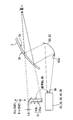
- the drawing It is a schematic diagram which shows the mounting state to the vehicle of the HUD apparatus in one Embodiment, It is a mimetic diagram showing a schematic structure of a HUD device in one embodiment, It is a schematic diagram showing a laser projection unit in one embodiment, It is a schematic diagram showing an optical system from the laser projection unit to the screen member in one embodiment, It is a top view for demonstrating drawing of the image in a screen member, and FIG. 6 is an enlarged view showing a laser beam corresponding to one pixel of FIG. 5 in an enlarged manner, for explaining chromatic aberration.
- a HUD device 100 according to an embodiment of the present disclosure shown in FIG. 1 is mounted on an instrument panel 2 of a vehicle 1 that is a kind of moving body.
- the HUD device 100 projects an image IM on a windshield 3 as a projection member of the vehicle 1.
- the HUD device 100 displays the virtual image VI that can be visually recognized by the occupant seated on the target seat 4 in the vehicle 1. That is, the light of the image IM reflected by the windshield 3 reaches the occupant's eyes in the interior of the vehicle 1 and the occupant perceives the light.
- the occupant can recognize various information displayed as the virtual image VI. Examples of various information displayed as the virtual image VI include vehicle state values such as vehicle speed and fuel remaining amount, or vehicle information such as road information and visibility assistance information.
- the windshield 3 of the vehicle 1 is located above the instrument panel 2 and is formed in a translucent plate shape with glass or synthetic resin. Further, the windshield 3 is disposed so as to be inclined toward the rear of the vehicle toward the upper side of the vehicle. In particular, as shown in FIG. 2, the surface 3 a facing the occupant side in the vehicle compartment in the windshield 3 is formed in a smooth concave shape or a planar shape. In the windshield 3, the back surface 3b facing away from the passenger outside the vehicle compartment is formed in a smooth convex shape or a flat shape. As the distance between the front surface 3a and the back surface 3b increases toward the top of the vehicle, the windshield 3 has a wedge-shaped section.
- the downward direction of the vehicle indicates a direction in which gravity is generated when the vehicle travels on a flat ground or stops on a flat ground.
- the upper side of the vehicle indicates the opposite direction of the lower side of the vehicle.
- the vehicle up-down direction indicates the vehicle upper side and the vehicle lower side.
- a direction along the vehicle vertical direction in the image IM is defined as an image vertical direction Diy
- a direction perpendicular to the vehicle vertical direction in the image IM is defined as an image horizontal direction Dix.
- such a HUD device 100 includes a laser projection unit 10, a scanning unit 20, a refraction element unit 30, a reflection element unit 40, a screen member 50, and a light guide unit 60 in a housing 70. It has.
- the laser projection unit 10 includes a plurality of laser oscillators 12a, 12b, and 12c, a plurality of collimating lenses 14a, 14b, and 14c, and a plurality of dichroic mirrors 16a, 16b, and 16c. .
- the laser oscillators 12a to 12c, collimating lenses 14a to 14c, and dichroic mirrors 16a to 16c are provided.
- the three laser oscillators 12a to 12c oscillate laser beams having different wavelengths.
- the laser oscillator 12a oscillates a green laser beam having a peak wavelength in the range of 490 to 530 nm, preferably 515 nm, for example.
- the laser oscillator 12b oscillates a blue laser beam having a peak wavelength in the range of 430 to 470 nm, preferably 450 nm, for example.
- the laser oscillator 12c oscillates a red laser beam having a peak wavelength in the range of 600 to 650 nm, preferably 640 nm, for example.
- Each laser beam emitted from each laser oscillator 12a to 12c is incident on a corresponding collimator lens 14a to 14c.
- the three collimating lenses 14a to 14c are arranged at predetermined intervals in the traveling direction of the respective laser beams with respect to the corresponding laser oscillators 12a to 12c. Each of the collimating lenses 14a to 14c refracts the corresponding color laser beam to collimate the laser beam.
- the three dichroic mirrors 16a to 16c are arranged at predetermined intervals in the traveling direction of each laser beam with respect to the corresponding collimating lenses 14a to 14c, respectively.
- Each of the dichroic mirrors 16a to 16c reflects a laser beam having a specific wavelength among the laser beams transmitted through the corresponding collimating lenses 14a to 14c, and transmits a laser beam having other wavelengths.
- the dichroic mirror 16a corresponding to the collimating lens 14a reflects the green laser beam.
- the dichroic mirror 16b corresponding to the collimating lens 14b reflects the blue laser beam and transmits the green laser beam.
- the dichroic mirror 16c corresponding to the collimating lens 14c reflects the red laser beam and transmits the green and red laser beams.
- the dichroic mirror 16b is arranged at a predetermined interval in the traveling direction of the green laser beam after being reflected by the dichroic mirror 16a.
- a dichroic mirror 16c is arranged at a predetermined interval in the traveling direction of the blue laser beam after being reflected by the dichroic mirror 16b.
- each of the laser oscillators 12 a to 12 c is electrically connected to the controller 18.
- Each laser oscillator 12a to 12c oscillates a laser beam in accordance with an electric signal from the controller 18.
- Various colors can be reproduced by adding and mixing the three color laser beams emitted from the laser oscillators 12a to 12c.
- the laser projection unit 10 projects the laser beams having different wavelengths from each other toward the scanning unit 20 in a state where the laser beams are superimposed.
- the scanning unit 20 has a scanning mirror 22 as shown in detail in FIG.
- the scanning mirror 22 is a MEMS mirror using a micro-electro-mechanical system (MEMS) that scans the laser beam by temporally changing the projection direction PD of the laser beam from the laser projection unit 10.
- MEMS micro-electro-mechanical system
- a reflective surface 22 c is formed on the surface facing the dichroic mirror 16 c with a predetermined distance by metal deposition of aluminum or the like.
- the reflection surface 22c is rotatable around two rotation axes Ax and Ay orthogonal to each other along the reflection surface 22c.
- Such a scanning mirror 22 is electrically connected to the controller 18 and can change the direction of the reflecting surface 22c in accordance with the scanning signal.
- the scanning unit 20 can scan the laser light beam in conjunction with the laser projection unit 10 by controlling the scanning mirror 22 by the controller 18.
- the laser light beam scanned by the scanning unit 20 enters the refractive element unit 30.
- the refractive element unit 30 is disposed on the optical path between the scanning unit 20 and the screen member 50, particularly in the present embodiment, on the optical path between the scanning unit 20 and the reflective element unit 40.
- the refractive element section 30 has a positive refractive power as a whole, and adjusts the incident angle of the laser light beam on the screen member 50 by refraction.
- the refractive element unit 30 includes a negative lens unit 32 having a negative refractive power and a positive lens unit 34 having a positive refractive power. Particularly in the present embodiment, the refractive element portion 30 is integrally formed by bonding the negative lens portion 32 and the positive lens portion 34 to each other.
- the negative lens unit 32 is disposed closer to the scanning unit 20 than the positive lens unit 34, and the positive lens unit 34 is disposed closer to the screen member 50 than the negative lens unit 32.
- the negative lens portion 32 is formed of a medium such as glass and has translucency.
- the negative lens unit 32 has a plurality of refractive surfaces 32a and 32b that refract the laser beam.
- the refractive surface 32a on the incident side is a convex spherical surface.
- the exit-side refracting surface 32 b is a concave spherical surface, and is shared with the incident-side refracting surface 34 a of the positive lens portion 34 by being bonded to the positive lens portion 34.
- the curvature radius of the entrance-side refracting surface 32a is set to be larger than the curvature radius of the exit-side refracting surface 32b, and the negative lens portion 32 is a concave lens having a meniscus shape.
- the positive lens part 34 is formed to have translucency by a medium such as glass.
- the positive lens unit 34 has a plurality of refractive surfaces 34a and 34b that refract the laser beam.
- the incident-side refracting surface 34 b is a convex spherical surface, and is shared with the exit-side refracting surface 32 b of the negative lens portion 32 by bonding to the negative lens portion 32 as described above.
- the exit-side refracting surface 34b is a convex aspheric surface, and in particular in the present embodiment, is a free-form surface. Therefore, the positive lens portion 34 is a biconvex lens.
- the laser beam is refracted and transmitted through such a refracting element part 30 and then enters the reflecting element part 40.
- the reflection element unit 40 is disposed on the optical path between the scanning unit 20 and the screen member 50, particularly in the present embodiment, on the optical path between the refraction element unit 30 and the screen member 50.
- the reflection element unit 40 has a free-form surface mirror 42.
- the free-form surface mirror 42 is formed by evaporating aluminum or the like as the reflective surface 42a on the surface of a base material made of synthetic resin or glass.
- the reflecting surface 42a is a concave free-form surface with a recessed center.
- the free-form surface mirror 42 of the reflection element unit 40 reflects the laser beam from the refraction element unit 30 toward the screen member 50, so that the incident angle of the laser beam to the screen member 50 in cooperation with the refraction element unit 30. Adjust. Specifically, the adjustment is performed so that the difference in the incident angle to the screen member 50 between the laser beams corresponding to each projection direction PD is minimized.
- the screen member 50 is a reflective screen formed by depositing aluminum on the surface of a base material made of synthetic resin or glass.
- the screen member 50 is formed as a micromirror array in which a plurality of small reflecting surfaces 52 are arranged in a projection area PA where a laser beam is projected.
- each reflecting surface 52 is formed in a concave shape having a sufficiently smaller radius of curvature than each surface 32a to 32b, 34a to 34b, 42a of the refractive element portion 30 and the reflecting element portion 40. It may be formed into a shape.
- an image IM is drawn on the screen member 50 by the incidence of the laser beam scanned by the scanning unit 20.
- the scanning unit 20 projects the laser beam toward the projection area PA of the screen member 50 while temporally changing the projection direction PD of the laser beam.
- the laser beam is sequentially scanned along the plurality of scanning lines SL under the control of the controller 18. As a result, the position where the laser light beam is incident moves in the projection area PA, and the laser light beam is intermittently irradiated with pulses, thereby rendering the image IM.
- the image IM drawn in the projection area PA is drawn, for example, as 60 frames per second as an image having 480 pixels in the xs direction along the scanning line SL and 240 pixels in the ys direction perpendicular to the scanning line SL.
- illustration of each reflective surface 52 is abbreviate
- the laser beam as the light of the image IM constituting each pixel is incident on the light guide unit 60 while being diffused by being reflected by each reflection surface 62a of the screen member 50.
- the light guide 60 has a concave mirror 62 as shown in FIG.
- the concave mirror 62 is formed by evaporating aluminum as the reflective surface 62a on the surface of a base material made of synthetic resin or glass.
- the reflecting surface 62a is formed in a smooth curved surface as a concave shape with a recessed central portion.
- the concave mirror 62 reflects the light of the image IM from the screen member 50 toward the windshield 3.
- a light-transmitting dustproof cover 72 is provided in the opening of the housing 70 above the vehicle, and the light of the image IM reflected by the concave mirror 62 passes through the dustproof cover 72 from below the vehicle, The light enters the windshield 3 above the vehicle.
- the light guide unit 60 enlarges the image IM drawn on the screen member 50 and guides it to the windshield 3.
- a plane mirror etc. can be added to the light guide part 60.
- the virtual image VIa reflected by the front surface 3a and the virtual image VIb reflected by the back surface 3b can be visually recognized as a virtual image VI as a slightly shifted double image.
- the windshield 3 has a cross-sectional wedge shape, for example, it is very difficult to completely match the positions of the virtual images VIa and VIb in the entire virtual image VI.
- the direction in which the virtual image VIb due to reflection on the back surface 3b deviates from the virtual image VIa due to reflection on the front surface 3a is defined as a shift parallel direction Dd1
- a direction perpendicular to the shift parallel direction Dd1 is defined as a shift vertical direction Dd2.
- the shift parallel direction Dd1 approximately matches the image vertical direction Diy
- the shift vertical direction Dd2 approximately matches the image horizontal direction Dix. Yes.
- the virtual image VI visually recognized by the occupant is enlarged by the light guide unit 60 and the windshield 3 with respect to the image IM drawn on the screen member 50.
- the magnification in the image vertical direction Diy is defined as My.
- the magnification in the shift parallel direction Dd1 is M1.
- the column of pixels arranged in the xs direction on the screen member 50 is in the image horizontal direction Dix.
- the pixel rows arranged in the ys direction are arranged along the image up-down direction Diy. That is, the xs direction constituting the image left-right direction Dix is a direction corresponding to the deviation vertical direction Dd2, and the ys direction constituting the image up-down direction Diy direction is a direction corresponding to the deviation parallel direction Dd1 (FIG. 4). (See also 5).
- the direction corresponding to the xs direction or the ys direction is defined as the direction in which the laser light beam moves by scanning in the xs direction, and the ls direction.
- the direction in which the laser light beam moves by the scanning is defined as the yl direction (see also FIG. 4).
- the focal length of the negative lens section 32 is set to f1
- the Abbe number of the negative lens section 32 is set to ⁇ 1 again.
- the focal length of the positive lens unit 34 in the xl direction is f2x
- the focal length of the positive lens unit 34 in the yl direction is f2y
- the Abbe number of the positive lens unit 34 is again ⁇ 2.
- the focal length in the xl direction corresponding to the image left-right direction Dix of the positive lens unit 34 is larger than the focal length in the yl direction corresponding to the image vertical direction Diy of the positive lens unit 34. It is getting longer.
- the radii of curvature in the xl direction corresponding to the image left-right direction Dix are in the image up-down direction Diy at each location including on the optical axis. It is larger than the corresponding radius of curvature in the yl direction.
- the focal length in the xl direction corresponding to the image left-right direction Dix as a whole is also the refractive element portion 30 as a whole in the yl direction corresponding to the image up-down direction Diy. Longer than focal length.
- the image IM drawn on the screen member 50 by the laser beam refracted and transmitted by the refraction element unit 30 will be described.
- the laser beam corresponding to one projection direction PD in the scanning of the scanning unit 20 corresponds to one pixel of the image IM.
- the incident position on the screen member 50 corresponds to one projection direction PD, and between the colors of the laser light beams in a state where different wavelengths are superimposed to form one pixel. Dislocation chromatic aberration may occur.
- the chromatic aberration Cx in the image horizontal direction Dix is smaller than the chromatic aberration Cy in the image vertical direction Diy in each laser beam corresponding to each projection direction PD by the refractive element unit 30 based on the above mathematical formula 1.
- the generated chromatic aberration Cx, Cy varies depending on each pixel of the image IM.
- the relationship between the chromatic aberration Cx, Cy is established in all the pixels. It is preferable. However, since the chromatic aberration Cx, Cy may not occur or may be extremely small in the first place with respect to the laser beam (for example, the pixel at the center of the image IM) that has passed through the paraxial axis of the refractive element unit 30, the chromatic aberration Cx, Cy described above may occur. The relationship may not be established.
- the chromatic aberration Cy in the image vertical direction Diy is between the virtual images VIa and VIb in each laser beam corresponding to each projection direction PD. It is smaller than the value obtained by dividing the component in the image vertical direction Diy of the shift amount Ld by the magnification My.
- the upper limit of the chromatic aberration Cy in the image vertical direction Diy is also preferably established in all pixels.
- the relationship between the chromatic aberrations Cx and Cy described above holds even when the image vertical direction Diy and the shift parallel direction Dd1 are read, and the image left-right direction Dix and the shift vertical direction Dd2 are read. That is, in the laser beam of the image IM drawn on the screen member 50, the chromatic aberration Cx is shifted, and the chromatic aberration C2 in the direction corresponding to the vertical direction Dd2 and the chromatic aberration C1 in the direction corresponding to the shifted chromatic aberration Cy are shifted. be able to. Furthermore, in this case, the relationship between the chromatic aberration Cy and the magnification My can be read as the relationship between the chromatic aberration C1 and the magnification M1.
- the laser light flux in a state where different wavelengths are superposed is refracted by the refractive element section 30.
- a separating action is performed in which the laser beam is separated for each wavelength.
- the laser beam is refracted by the negative lens portion 32, a canceling action that cancels the separation action occurs.
- the negative lens portion 32 is formed of a medium that is more highly dispersed than the positive lens portion 34, even if the refractive element portion 30 has a positive refractive power as a whole, the balance between the separating action and the canceling action. Can take.
- the incident angle to the screen member 50 can be adjusted by the refractive element unit 30 while maintaining the overlapping state of the laser beam. Since the chromatic aberration Cx, Cy (C1, C2) of the image IM drawn on the screen member 50 is suppressed, the visibility of the virtual image VI that is visible by projecting the image IM onto the windshield 3 can be improved. it can.
- the chromatic aberration C2 in the direction corresponding to the shift vertical direction Dd2 is smaller than the chromatic aberration C1 in the direction corresponding to the shift parallel direction Dd1.
- the chromatic aberration C1 in the deviation vertical direction Dd2 is preferentially removed while allowing the chromatic aberration C1 in the deviation parallel direction Dd1 to some extent, so that the visibility improvement effect by the refractive element unit 30 can be enhanced.
- the chromatic aberration C1 in the direction corresponding to the shift parallel direction Dd1 is a shift between the virtual images VIa and VIb due to the reflection of the front surface 3a and the back surface 3b. It is smaller than the value obtained by dividing the amount Ld by the magnification M1. Even if such a chromatic aberration C1 is displayed as a virtual image under the influence of enlargement by the light guide 60 and the windshield 3, it is smaller than the shift amount Ld. Therefore, even when the chromatic aberration C2 in the deviation vertical direction Dd2 is preferentially removed, it is possible to suppress deterioration in visibility due to the chromatic aberration C1 in the deviation parallel direction Dd1.
- the image IM is projected from the HUD device 100 mounted on the instrument panel 2 onto the windshield 3 above the vehicle.
- the image IM is projected onto the windshield 3 formed in a translucent plate shape having the front surface 3a facing the passenger side and the back surface 3b facing the opposite side of the front surface 3a, a virtual image due to reflection on the front surface 3a.
- the virtual image VIb caused by reflection on the back surface 3b with respect to VIa is easily shifted in the image vertical direction Diy. For this reason, even if the chromatic aberration Cy in the image vertical direction Diy is preferentially removed by the refraction element unit 30, the effect of improving the visibility is small because the virtual images VIa and VIb eventually shift.
- the chromatic aberration Cx in the image horizontal direction Dix is smaller than the chromatic aberration Cy in the image vertical direction Diy.
- the chromatic aberration Cx in the horizontal direction Dix of the image is preferentially removed while allowing the chromatic aberration Cy in the vertical direction Diy of the image to some extent, so that the effect of improving the visibility by the refractive element unit 30 can be enhanced.
- the focal length in the xl direction corresponding to the image left-right direction Dix of the refraction element unit 30 is longer than the focal length in the yl direction corresponding to the image up-down direction Diy of the refraction element unit 30.
- Equation 1 is established, and the chromatic aberration Cx can be preferentially removed.
- the chromatic aberration Cy in the image vertical direction Diy is an image having a deviation amount Ld between the virtual images VIa and VIb due to reflection of the front surface 3a and the back surface 3b. It is smaller than the value obtained by dividing the vertical Diy component by the magnification My. Even if such chromatic aberration Cy is influenced by the light guide 60 and the windshield 3 and is displayed as a virtual image, the chromatic aberration Cy becomes smaller than the image vertical direction Diy component of the shift amount Ld. Therefore, even when the chromatic aberration Cx in the horizontal direction Dix of the image is preferentially removed, it is possible to suppress the deterioration of visibility due to the chromatic aberration Cy in the vertical direction Diy of the image.
- the refracting surface 34b arranged closest to the screen member 50 among the plurality of refracting surfaces 32a to 32b and 34a to 34b of the refracting element unit 30 is an aspherical surface.
- the laser light beam scanned by the scanning unit 20 can further pass through the outer peripheral side of the refracting surface 34b, so that the aberration correction effect by the aspherical surface can be reliably obtained. it can.
- the reflection element unit 40 that reflects the laser beam is disposed on the optical path between the scanning unit 20 and the screen member 50. Even if such a reflective element section 40 is added, it does not cause an increase in chromatic aberration, so that the quality of the image IM can be improved while suppressing chromatic aberration Cx, Cy (C1, C2). *
- the refracting element unit 30 is disposed between the scanning unit 20 and the reflecting element unit 40, the refracting element unit 30 is transmitted before the laser beam scanned by the scanning unit 20 is sufficiently expanded. Therefore, the refractive element part 30 can be reduced in size.
- the reflective element unit 40 may be disposed on the optical path between the scanning unit 20 and the refractive element unit 30.
- the reflective element unit 40 may not be provided, and only the refractive element unit 30 may be disposed on the optical path between the scanning unit 20 and the screen member 50.
- the negative lens portion 32 and the positive lens portion 34 are not bonded to each other, and may be formed separately. Specifically, a gap may be provided between the exit-side refractive surface 32 b of the negative lens unit 32 and the incident-side refractive surface 34 a of the positive lens unit 34, and the negative lens unit 32 and the positive lens unit 34 may be provided. And may be arranged slightly apart.
- the positive lens unit 34 may be arranged closer to the scanning unit 20 than the negative lens unit 32.
- each of the refracting surfaces 32a to 32b and 34a to 34b of the refracting element unit 30 is not limited to a combination where the refracting surfaces 32a to 32b and 34a are spherical surfaces and the refracting surface 34b is a free curved surface
- a spherical surface, a rotationally symmetric aspherical surface, a cylindrical surface, a free-form surface, and the like can be employed.
- the shift parallel direction Dd1 and the image vertical direction Diy do not have to match.
- the shift vertical direction Dd2 and the image left-right direction Dix do not have to match.
- the focal length in the direction corresponding to the deviation vertical direction Dd2 of the refractive element unit 30 may be equal to or less than the focal length in the direction corresponding to the deviation parallel direction Dd1 of the refractive element unit 30.
- the focal length of the refraction element unit 30 in the direction corresponding to the image horizontal direction Dix may be equal to or smaller than the focal length of the refraction element unit 30 in the direction corresponding to the image vertical direction.
- the chromatic aberration Cy in the direction corresponding to the shift parallel direction Dd1 is the shift amount Ld between the virtual images VIa and VIb due to the reflection of the front surface 3a and the back surface 3b. May be greater than or equal to the value obtained by dividing by the magnification My in the parallel direction. As an example of this, the chromatic aberration Cy may be smaller than the value only in a partial region such as the upper half (or the lower half) of the image IM.
- the projection member may have a constant distance between the front surface 3a and the back surface 3b.
- the projection member may be a combiner provided separately from the windshield 3.
- the projection member may be one in which the displacement of the virtual images VIa and VIb due to the reflection of the front surface 3a and the back surface 3b may not occur, or may not generate the virtual image VIb due to the reflection of the back surface 3b.
- the present disclosure may be applied to various moving bodies (transportation equipment) such as ships or airplanes other than the vehicle 1.
- the present disclosure relates to a head-up display device that displays the virtual images VI, VIa, and VIb that are mounted on the moving body 1 and are visible to the occupant by projecting the image IM onto the projection member 3.
- the head-up display device includes a laser projection unit 10, a scanning unit 20, a screen member 50, and a refractive element unit 30.
- the laser projection unit 10 projects a plurality of laser beams having different wavelengths from each other.
- the scanning unit 20 scans the laser beam from the laser projection unit. An image is drawn on the screen member 50 by the incidence of the laser beam scanned by the scanning unit.
- the refracting element unit 30 is disposed on the optical path between the scanning unit and the screen member, has a positive refracting power as a whole, and adjusts the incident angle of the laser beam to the screen member by refraction.
- the refractive element section includes a positive lens section 34 having a positive refractive power, and a negative lens section 32 that is formed of a medium having a higher dispersion than the positive lens section and has a negative refractive power.
- the laser light beams in the state where the mutually different wavelengths are superimposed are refracted by the refractive element portion.
- a separation action is generated in which the laser beam is separated for each wavelength.
- the laser beam is refracted by the negative lens portion, a canceling action that cancels the separation action occurs.
- the negative lens portion is formed of a medium having higher dispersion than the positive lens portion, even if the refractive element portion has a positive refractive power as a whole, a balance between the separation action and the cancellation action should be achieved. Can do.
- the incident angle to the screen member can be adjusted by the refractive element unit while maintaining the overlapping state of the laser beam. Since the chromatic aberration of the image drawn on the screen member is suppressed, the visibility of the virtual image that can be viewed by projecting the image on the projection member can be improved.
Landscapes
- Engineering & Computer Science (AREA)
- Physics & Mathematics (AREA)
- Mechanical Engineering (AREA)
- Chemical & Material Sciences (AREA)
- Combustion & Propulsion (AREA)
- Transportation (AREA)
- General Physics & Mathematics (AREA)
- Optics & Photonics (AREA)
- Instrument Panels (AREA)
- Mechanical Optical Scanning Systems (AREA)
- Lenses (AREA)
- Fittings On The Vehicle Exterior For Carrying Loads, And Devices For Holding Or Mounting Articles (AREA)
Abstract
HUD装置は、車両に搭載され、ウインドシールドに画像を投影することにより、乗員により視認可能な虚像を表示する。レーザ投射部(10)は、互いに波長が異なる複数のレーザ光束を重ね合わせて投射する。走査部(20)は、レーザ投射部(10)からのレーザ光束を走査する。スクリーン部材(50)には、走査部(20)に走査されたレーザ光束の入射により、画像が描画される。屈折素子部(30)は、走査部(20)とスクリーン部材(50)との間の光路上に配置され、正の屈折力を有し、スクリーン部材(50)へのレーザ光束の入射角を屈折により調整する。屈折素子部(30)は、正の屈折力を有する正レンズ部(34)と、正レンズ部(34)よりも高分散の媒質により形成され、負の屈折力を有する負レンズ部(32)と、を有する。
Description
本出願は、2016年1月19日に出願された日本出願番号2016-8265号に基づくもので、ここにその記載内容を援用する。
本開示は、移動体に搭載され、乗員により視認可能な虚像を表示するヘッドアップディスプレイ装置(以下、HUD装置を略称とする)に関する。
従来、移動体に搭載され、乗員により視認可能に虚像を表示するHUD装置が知られている。特許文献1に開示のHUD装置は、レーザ投射部、走査部、スクリーン部材、及び屈折素子部を備えている。レーザ投射部は、互いに波長が異なる複数のレーザ光束を重ね合わせて投射する。走査部は、レーザ投射部からのレーザ光束を走査する。スクリーン部材は、走査部に走査されたレーザ光束の入射により、画像が描画される部材である。屈折素子部は、走査部とスクリーン部材との間の光路上に配置され、正の屈折力を有し、スクリーン部材へのレーザ光束の入射角を屈折により調整する。より詳細に屈折素子部は、単一のレンズにより構成されている。
特許文献1の構成では、互いに異なる波長を重ね合わせた状態のレーザ光束により、スクリーン部材に画像が描画される。しかしながら、走査部による走査により単一のレンズの各箇所を透過するレーザ光束は、当該レンズ媒質の分散性により各色に分離してしまい、スクリーン部材に描画される画像に色収差が発生し得る。このような画像を投影部材に投影した虚像では、当該色収差によって視認性に悪影響が及ぶことが懸念されている。
本開示は、以上説明した問題に鑑みてなされたものであって、その目的は、虚像の視認性が高いHUD装置を提供することを目的とする。
本開示の第一の態様において、ヘッドアップディスプレイ装置は、移動体に搭載され、投影部材に画像を投影することにより、乗員により視認可能な虚像を表示する。ヘッドアップディスプレイ装置は、互いに波長が異なる複数のレーザ光束を重ね合わせて投射するレーザ投射部を備える。ヘッドアップディスプレイ装置は、前記レーザ投射部からの前記レーザ光束を走査する走査部を更に備える。ヘッドアップディスプレイ装置は、前記走査部に走査された前記レーザ光束の入射により、前記画像が描画されるスクリーン部材を更に備える。ヘッドアップディスプレイ装置は、前記走査部と前記スクリーン部材との間の光路上に配置され、全体として正の屈折力を有し、前記スクリーン部材への前記レーザ光束の入射角を屈折により調整する屈折素子部を更に備える。前記屈折素子部は、正の屈折力を有する正レンズ部を備える。前記屈折素子部は、前記正レンズ部よりも高分散の媒質により形成され、負の屈折力を有する負レンズ部を更に備える。
本開示についての上記目的およびその他の目的、特徴や利点は、添付の図面を参照しながら下記の詳細な記述により、より明確になる。その図面は、
一実施形態におけるHUD装置の車両への搭載状態を示す模式図であり、
一実施形態におけるHUD装置の概略構成を示す模式図であり、
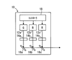
一実施形態におけるレーザ投射部を示す模式図であり、
一実施形態におけるレーザ投射部からスクリーン部材に至る光学系を示す模式図であり、
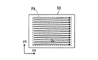
スクリーン部材における画像の描画を説明するための平面図であり、また
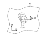
図5の一画素に対応するレーザ光束を拡大して示す拡大図であって、色収差を説明するための図である。
以下、本開示の一実施形態を図面に基づいて説明する。
図1に示す本開示の一実施形態によるHUD装置100は、移動体の一種である車両1のインストルメントパネル2に搭載されている。HUD装置100は、車両1の投影部材としてのウインドシールド3に画像IMを投影する。これにより、HUD装置100は、車両1において対象座席4に着座した乗員により視認可能な虚像VIを表示する。すなわち、ウインドシールド3に反射される画像IMの光が、車両1の室内において乗員の眼に到達し乗員が当該光を知覚する。そして、乗員は、虚像VIとして表示される各種情報を認識することができる。虚像VIとして表示される各種情報としては、例えば、車速、燃料残量等の車両状態値、又は道路情報、視界補助情報等の車両情報が挙げられる。
車両1のウインドシールド3は、インストルメントパネル2よりも車両上方に位置し、ガラスないしは合成樹脂等により透光性の板状に形成されている。また、ウインドシールド3は、車両上方に向かう程車両後方に傾斜して配置されている。特に図2に示すように、ウインドシールド3において車室内の乗員側を向く表面3aは、滑らかな凹面状又は平面状に形成されている。ウインドシールド3において車室外の乗員とは反対側を向く裏面3bは、滑らかな凸面状又は平面状に形成されている。表面3aと裏面3bとの間隔が車両上方に向かう程大きくなることで、ウインドシールド3は、断面楔形状の箇所を有している。
ここで本実施形態において、車両下方とは、車両が平地を走行するとき又は平地に停止するときに重力が生ずる方向を示す。車両上方とは、車両下方の反対方向を示す。車両上下方向とは、車両上方及び車両下方を示すものとする。
そして、画像IMが虚像VIとして表示されるときに、当該画像IMにおいて車両上下方向に沿う方向を画像上下方向Diyとし、当該画像IMにおいて車両上下方向と垂直な方向を画像左右方向Dixとする。
このようなHUD装置100は、図1,2に示すように、ハウジング70内において、レーザ投射部10、走査部20、屈折素子部30、反射素子部40、スクリーン部材50、及び導光部60を備えている。
レーザ投射部10は、図3に詳細を示すように、複数のレーザ発振器12a,12b,12c、複数のコリメートレンズ14a,14b,14c、及び複数のダイクロイックミラー16a,16b,16cを有している。本実施形態では、レーザ発振器12a~12c、コリメートレンズ14a~14c、ダイクロイックミラー16a~16cは3つずつ設けられている。
3つのレーザ発振器12a~12cは、波長が互いに異なるレーザ光束を発振する。具体的に、レーザ発振器12aは、例えばピーク波長が490~530nmの範囲、好ましくは515nmである緑色のレーザ光束を発振するようになっている。レーザ発振器12bは、例えばピーク波長が430~470nmの範囲、好ましくは450nmである青色のレーザ光束を発振するようになっている。レーザ発振器12cは、例えばピーク波長が600~650nmの範囲、好ましくは640nmである赤色のレーザ光束を発振するようになっている。各レーザ発振器12a~12cから発振された各レーザ光束は、それぞれ対応するコリメートレンズ14a~14cに入射する。
3つのコリメートレンズ14a~14cは、それぞれ対応するレーザ発振器12a~12cに対して、各レーザ光束の進行方向に所定の間隔をあけて配置されている。各コリメートレンズ14a~14cは、対応する色のレーザ光束を屈折させることにより、当該レーザ光束を平行化する。
3つのダイクロイックミラー16a~16cは、それぞれ対応するコリメートレンズ14a~14cに対して、各レーザ光束の進行方向に所定の間隔をあけて配置されている。各ダイクロイックミラー16a~16cは、対応するコリメートレンズ14a~14cを透過した各レーザ光束のうち、特定波長のレーザ光束を反射し、その他の波長のレーザ光束を透過させる。具体的には、コリメートレンズ14aに対応するダイクロイックミラー16aは、緑色のレーザ光束を反射する。コリメートレンズ14bに対応するダイクロイックミラー16bは、青色のレーザ光束を反射し、緑色のレーザ光束を透過させる。コリメートレンズ14cに対応するダイクロイックミラー16cは、赤色のレーザ光束を反射し、緑色及び赤色のレーザ光束を透過させる。
ここで、ダイクロイックミラー16aによる反射後の緑色のレーザ光束の進行方向には、ダイクロイックミラー16bが所定の間隔をあけて配置されている。また、ダイクロイックミラー16bの反射後の青色のレーザ光束の進行方向には、ダイクロイックミラー16cが所定の間隔をあけて配置されている。これら配置形態により、ダイクロイックミラー16aによる反射後の緑色のレーザ光束が、ダイクロイックミラー16bを透過し、ダイクロイックミラー16bによる反射後の青色のレーザ光束と重ね合される。また、緑色のレーザ光束と青色のレーザ光束とが、ダイクロイックミラー16cを透過し、ダイクロイックミラー16cによる反射後の赤色のレーザ光束と重ね合される。
ここで、各レーザ発振器12a~12cは、コントローラ18と電気的に接続されている。各レーザ発振器12a~12cは、コントローラ18からの電気信号に従って、レーザ光束を発振する。そして、各レーザ発振器12a~12cから発振される3色のレーザ光束を加色混合することで、種々の色の再現が可能となる。こうしてレーザ投射部10は、互いに波長が異なる複数のレーザ光束を重ね合わせた状態で、走査部20へ向けて投射する。
走査部20は、図4に詳細を示すように、走査ミラー22を有している。走査ミラー22は、レーザ投射部10からのレーザ光束の投射方向PDを時間的に変えることで、当該レーザ光束を走査する微小電気機械システム(Micro Electro Mechanical Systems:MEMS)を用いたMEMSミラーである。走査ミラー22において、ダイクロイックミラー16cと所定の間隔をあけて対向する面には、アルミニウムの金属蒸着等により、反射面22cが形成されている。反射面22cは、当該反射面22cに沿って直交する2つの回転軸Ax,Ayまわりに回動可能となっている。
このような走査ミラー22は、コントローラ18と電気的に接続されており、その走査信号に従って、反射面22cの向きを変えることができる。こうして、走査部20は、走査ミラー22がコントローラ18により制御されることで、レーザ投射部10と連動して、レーザ光束を走査することが可能となっている。走査部20により走査されたレーザ光束は、屈折素子部30に入射するようになっている。
屈折素子部30は、走査部20とスクリーン部材50との間の光路上、特に本実施形態では走査部20と反射素子部40との間の光路上に配置されている。屈折素子部30は、全体として正の屈折力を有し、スクリーン部材50へのレーザ光束の入射角を屈折により調整する。
屈折素子部30は、負の屈折力を有する負レンズ部32、及び正の屈折力を有する正レンズ部34を有している。特に本実施形態では、屈折素子部30は、負レンズ部32と正レンズ部34とを互いに貼り合わせて一体的に形成されている。負レンズ部32は、正レンズ部34よりも走査部20側に配置され、正レンズ部34は、負レンズ部32よりもスクリーン部材50側に配置されている。
負レンズ部32は、ガラス等の媒質により透光性を有して形成されている。負レンズ部32の媒質は、例えば屈折率nd=1.92、アッベ数νd=31であり、正レンズ部34の媒質よりも高屈折率かつ高分散となっている。
負レンズ部32は、レーザ光束を屈折させる複数の屈折面32a,32bを有している。具体的に、入射側の屈折面32aは凸形状の球面となっている。射出側の屈折面32bは凹形状の球面となっており、正レンズ部34との貼り合わせにより、正レンズ部34の入射側の屈折面34aと共有されている。入射側の屈折面32aの曲率半径が射出側の屈折面32bの曲率半径よりも大きく設定されており、負レンズ部32は、メニスカス形状を呈する凹レンズとなっている。
正レンズ部34は、ガラス等の媒質により透光性を有して形成されている。正レンズ部34の媒質は、例えば屈折率nd=1.44、アッベ数νd=95であり、負レンズ部32の媒質よりも低屈折率かつ低分散となっている。
正レンズ部34は、レーザ光束を屈折させる複数の屈折面34a,34bを有している。具体的に、入射側の屈折面34bは凸形状の球面となっており、負レンズ部32との貼り合わせにより、上述のように負レンズ部32の射出側の屈折面32bと共有されている。射出側の屈折面34bは、凸形状の非球面であり、特に本実施形態では自由曲面となっている。したがって正レンズ部34は両凸レンズとなっている。
レーザ光束は、このような屈折素子部30を屈折及び透過した後、反射素子部40に入射するようになっている。
反射素子部40は、走査部20とスクリーン部材50との間の光路上、特に本実施形態では屈折素子部30とスクリーン部材50との間の光路上に配置されている。反射素子部40は、自由曲面ミラー42を有している。
自由曲面ミラー42は、合成樹脂ないしはガラス等からなる基材の表面に、反射面42aとしてアルミニウム等を蒸着させること等により形成されている。反射面42aは、中心が凹む凹形状の自由曲面となっている。反射素子部40の自由曲面ミラー42は、屈折素子部30からのレーザ光束をスクリーン部材50に向けて反射することにより、屈折素子部30と共同して、スクリーン部材50へのレーザ光束の入射角を調整する。具体的には、各投射方向PDに対応するレーザ光束間におけるスクリーン部材50への入射角の差が極力小さくなるように調整する。
スクリーン部材50は、合成樹脂ないしはガラス等からなる基材の表面にアルミニウムを蒸着させること等により形成された、反射型のスクリーンである。スクリーン部材50は、レーザ光束が投射される投射領域PAにおいて、複数の小さな反射面52が配列されたマイクロミラーアレイとして形成されている。特に本実施形態では、各反射面52が屈折素子部30及び反射素子部40の各面32a~32b,34a~34b,42aよりも十分に曲率半径が小さい凹形状に形成されているが、凸形状に形成されてもよい。
図5に示すように、スクリーン部材50には、走査部20に走査されたレーザ光束の入射により、画像IMが描画される。具体的に、走査部20は、レーザ光束の投射方向PDを時間的に変えながら、スクリーン部材50の投射領域PAに向けて当該レーザ光束を投射する。コントローラに18よる制御により、レーザ光束は、複数の走査線SLに沿って順次走査される。その結果、投射領域PAにおいてレーザ光束が入射する位置が移動していくと共に、レーザ光束が断続的にパルス照射されることで、画像IMが描画されることとなる。こうして投射領域PAに描画される画像IMは、例えば走査線SLに沿ったxs方向に480画素かつ走査線SLと垂直なys方向に240画素を有する画像として、毎秒60フレーム描画される。なお、図5では、各反射面52の図示が省略されている。
スクリーン部材50の各反射面62aに反射されることにより、各画素を構成する画像IMの光としてのレーザ光束は、拡散されつつ、導光部60へと入射する。
導光部60は、図2に示すように、凹面ミラー62を有している。凹面ミラー62は、合成樹脂ないしはガラス等からなる基材の表面に反射面62aとしてアルミニウムを蒸着させること等により形成される。反射面62aは、中心部が凹む凹形状として、滑らかな曲面状に形成されている。そして、凹面ミラー62は、スクリーン部材50からの画像IMの光をウインドシールド3へ向けて反射する。
ハウジング70の車両上方の開口部には、透光性の防塵カバー72が設けられており、凹面ミラー62に反射された画像IMの光は、車両下方から、当該防塵カバー72を透過して、車両上方のウインドシールド3へ入射する。こうして導光部60は、スクリーン部材50に描画される画像IMを拡大してウインドシールド3へ導光する。なお、導光部60には、平面ミラー等を追加することができる。
図2に示すように、ウインドシールド3の表面3aでは、画像IMの光の多くが乗員へ向けて反射される一方、ウインドシールド3の媒質内へ入射する光も存在し得る。このような光の一部は、裏面3bにて反射され、さらに表面3aから乗員へ向けて射出される。こうして、乗員からは、虚像VIとして、表面3aでの反射による虚像VIaと、裏面3bでの反射による虚像VIbとが、少しずれた二重像として視認され得る。前述のようにウインドシールド3が例えば断面楔形状を呈していたとしても、虚像VIの全体において各虚像VIa,VIbの位置を完全に一致させることは非常に困難である。
ここで、表面3aでの反射による虚像VIaに対して裏面3bでの反射による虚像VIbがずれる方向をずれ平行方向Dd1と、ずれ平行方向Dd1と垂直な方向をずれ垂直方向Dd2と、それぞれ定義する。画像IMの光が車両上下方向に沿ってウインドシールド3へ入射する本実施形態では、ずれ平行方向Dd1は画像上下方向Diyとおよそ合っており、ずれ垂直方向Dd2は画像左右方向Dixとおよそ合っている。
本実施形態では、スクリーン部材50に描画される画像IMに対して、乗員に視認される虚像VIは、導光部60及びウインドシールド3により拡大される。この拡大される倍率のうち画像上下方向Diyの倍率をMyとする。またずれ平行方向Dd1の倍率をM1とする。
また、スクリーン部材50から導光部60及びウインドシールド3に反射された画像IMの光により結像される虚像VIにおいて、スクリーン部材50上においてxs方向に並ぶ画素の列は、画像左右方向Dixに沿って並ぶようになっており、ys方向に並ぶ画素の列は、画像上下方向Diyに沿って並ぶようになっている。すなわち、画像左右方向Dixを構成するxs方向は、ずれ垂直方向Dd2に対応する方向であり、画像上下方向Diy方向を構成するys方向はずれ平行方向Dd1に対応する方向となっている(図4,5も参照)。さらに、屈折素子部30の各屈折面32a~32b,34a~34b上においてxs方向又はys方向に対応する方向として、xs方向への走査によりレーザ光束が移動する方向をxl方向とし、ys方向への走査によりレーザ光束が移動する方向をyl方向とする(図4も参照)。
ここで、図4に示す屈折素子部30において、負レンズ部32の焦点距離をf1とし、改めて負レンズ部32のアッベ数をν1とする。正レンズ部34のxl方向の焦点距離をf2xとし、正レンズ部34のyl方向の焦点距離をf2yとし、改めて正レンズ部34のアッベ数をν2とすると、本実施形態では、
1/f1・ν1+1/f2x・ν2<1/f1・ν1+1/f2y・ν2…(数式1)が成立するように設計されている。これを整理すると、f2y<f2xとなるので、正レンズ部34の画像左右方向Dixに対応するxl方向の焦点距離は、正レンズ部34の画像上下方向Diyに対応するyl方向の焦点距離よりも長くなっている。
1/f1・ν1+1/f2x・ν2<1/f1・ν1+1/f2y・ν2…(数式1)が成立するように設計されている。これを整理すると、f2y<f2xとなるので、正レンズ部34の画像左右方向Dixに対応するxl方向の焦点距離は、正レンズ部34の画像上下方向Diyに対応するyl方向の焦点距離よりも長くなっている。
具体的に本実施形態では、正レンズ部34の射出側の屈折面34bにおいて、光軸上をはじめとする各箇所では、画像左右方向Dixに対応するxl方向の曲率半径が画像上下方向Diyに対応するyl方向の曲率半径よりも大きくなっている。
他方の負レンズ部32は回転対称形状となっているので、結局、屈折素子部30全体としても、画像左右方向Dixに対応するxl方向の焦点距離は、画像上下方向Diyに対応するyl方向の焦点距離よりも長い。
このような屈折素子部30にて屈折及び透過するレーザ光束によって、スクリーン部材50に描画される画像IMについて、ここで説明する。上述のように走査部20の走査において一投射方向PDに対応するレーザ光束が、画像IMの一画素に対応する。ここで図6に模式的に示すように、一投射方向PDに対応し、一画素を構成するために互いに異なる波長を重ね合わせた状態のレーザ光束の各色間において、スクリーン部材50への入射位置がずれる色収差が生じ得る。
上記数式1に基づいた屈折素子部30により、各投射方向PDに対応する各レーザ光束において、画像左右方向Dixにおける色収差Cxは、画像上下方向Diyにおける色収差Cyよりも小さくなっている。
各投射方向PDに対応してレーザ光束の光路が異なるため、発生する色収差Cx,Cyは画像IMの各画素によって異なるものとなるが、この色収差Cx,Cyの関係は、全ての画素において成立することが好ましい。ただし、屈折素子部30の近軸を透過したレーザ光束(例えば画像IMの中央部の画素)に関しては、そもそも当該色収差Cx,Cyが発生しない又は極めて小さい場合があるため、上述の色収差Cx,Cyの関係が成立していなくてもよい。
さらに、例えば正レンズ部34の射出側の屈折面34bの形状を適宜設計することにより、各投射方向PDに対応する各レーザ光束において、画像上下方向Diyにおける色収差Cyは、虚像VIa,VIb間のずれ量Ldの画像上下方向Diyの成分を、倍率Myで除算した値よりも小さくなっている。この画像上下方向Diyにおける色収差Cyの上限についても、全ての画素において成立することが好ましい。
なお、本実施形態において上述の色収差Cx,Cyの関係は、画像上下方向Diyとずれ平行方向Dd1とを、画像左右方向Dixとずれ垂直方向Dd2とを、それぞれ読み替えても成立する。すなわち、スクリーン部材50に描画される画像IMのレーザ光束において、色収差Cxをずれ垂直方向Dd2に対応する方向の色収差C2と、色収差Cyをずれ平行方向Dd1に対応する方向の色収差C1と、それぞれ読替えることができる。さらにこの場合において、色収差Cyと倍率Myとの関係を、色収差C1と倍率M1との関係に読み替えることができる。
(作用効果)
以上説明した本実施形態の作用効果を以下に説明する。
以上説明した本実施形態の作用効果を以下に説明する。
本実施形態によると、互いに異なる波長を重ね合わせた状態のレーザ光束が、屈折素子部30にて屈折される。ここで、レーザ光束が正レンズ部34にて屈折される際には、当該レーザ光束が波長毎に分離される分離作用が生じる。これに対してレーザ光束が負レンズ部32にて屈折される際には、当該分離作用を打ち消す打消作用が生じる。ここで、負レンズ部32は、正レンズ部34よりも高分散の媒質により形成されているので、屈折素子部30が全体として正の屈折力であっても、分離作用と打消作用とのバランスを取ることができる。こうして、レーザ光束が走査部20により走査されても、当該レーザ光束の重なり状態を維持した状態で、屈折素子部30によりスクリーン部材50への入射角を調整することが可能となる。スクリーン部材50に描画される画像IMの色収差Cx,Cy(C1,C2)が抑制されるので、当該画像IMをウインドシールド3に投影させることで視認可能となる虚像VIにおける視認性を高めることができる。
また、乗員側を向く表面3a及び表面3aの反対側を向く裏面3bを有する透光性の板状に形成されるウインドシールド3に画像IMを投影する場合では、表面3aでの反射による虚像VIaに対して裏面3bでの反射による虚像VIbがずれて表示され得る。このため、ずれ平行方向Dd1の色収差C1を屈折素子部30によって優先的に除去しても、結局、虚像VIa,VIbのずれが生じているため視認性の改善効果は小さい。そこで本実施形態では、スクリーン部材50に描画される画像IMのレーザ光束において、ずれ垂直方向Dd2に対応する方向における色収差C2は、ずれ平行方向Dd1に対応する方向における色収差C1よりも小さくなっている。すなわち、ずれ平行方向Dd1の色収差C1をある程度許容しつつ、ずれ垂直方向Dd2の色収差C2が優先的に除去されることで、屈折素子部30による視認性の改善効果を高めることができる。
また、本実施形態によると、スクリーン部材50に描画される画像IMのレーザ光束において、ずれ平行方向Dd1に対応する方向における色収差C1は、表面3a及び裏面3bの反射による虚像VIa,VIb間のずれ量Ldを倍率M1で除算した値よりも小さくなっている。こうした色収差C1が導光部60及びウインドシールド3にて拡大の影響を受けて虚像表示されても、ずれ量Ldよりも小さくなる。したがって、ずれ垂直方向Dd2の色収差C2が優先的に除去された場合においても、ずれ平行方向Dd1の色収差C1によって視認性が悪化することを抑制することができる。
また、インストルメントパネル2に搭載されるHUD装置100から、車両上方のウインドシールド3に画像IMを投影する。ここで、乗員側を向く表面3a及び表面3aの反対側を向く裏面3bを有する透光性の板状に形成されるウインドシールド3に画像IMを投影する場合では、表面3aでの反射による虚像VIaに対して裏面3bでの反射による虚像VIbが、画像上下方向Diyにずれて表示され易い。このため、画像上下方向Diyの色収差Cyを屈折素子部30によって優先的に除去しても、結局、虚像VIa,VIbのずれが生じているため視認性の改善効果は小さい。そこで本実施形態では、スクリーン部材50に描画される画像IMのレーザ光束において、画像左右方向Dixにおける色収差Cxは、画像上下方向Diyにおける色収差Cyよりも小さくなっている。すなわち、画像上下方向Diyの色収差Cyをある程度許容しつつ、画像左右方向Dixの色収差Cxが優先的に除去されることで、屈折素子部30による視認性の改善効果を高めることができる。
また、本実施形態によると、屈折素子部30の画像左右方向Dixに対応するxl方向の焦点距離は、屈折素子部30の画像上下方向Diyに対応するyl方向の焦点距離よりも長い。このような条件により、例えば数式1が成立することとなり、色収差Cxを優先的に除去することが可能となる。
また、本実施形態によると、スクリーン部材50に描画される画像IMのレーザ光束において、画像上下方向Diyにおける色収差Cyは、表面3a及び裏面3bの反射による虚像VIa,VIb間のずれ量Ldの画像上下方向Diy成分を倍率Myで除算した値よりも小さくなっている。こうした色収差Cyが導光部60及びウインドシールド3にて拡大の影響を受けて虚像表示されても、ずれ量Ldの画像上下方向Diy成分よりも小さくなる。したがって、画像左右方向Dixの色収差Cxが優先的に除去された場合においても、画像上下方向Diyの色収差Cyによって視認性が悪化することを抑制することができる。
また、本実施形態によると、屈折素子部30の複数の屈折面32a~32b,34a~34bのうち最もスクリーン部材50側に配置される屈折面34bは、非球面である。最もスクリーン部材50側に配置される屈折面34bでは、走査部20により走査されるレーザ光束がより屈折面34bの外周側を透過可能となるので、非球面による収差補正効果を確実に得ることができる。
また、本実施形態によると、レーザ光束を反射する反射素子部40が走査部20とスクリーン部材50との間の光路上に配置されている。このような反射素子部40が追加されても、色収差増大の原因とはならないので、色収差Cx,Cy(C1,C2)を抑制しつつ、画像IMの質を高めることができる。
また、本実施形態によると、屈折素子部30が走査部20と反射素子部40との間に配置されるので、走査部20により走査されるレーザ光束が十分拡がる前に屈折素子部30を透過することとなるため、屈折素子部30を小型化することができる。
(他の実施形態)
以上、本開示の一実施形態について説明したが、本開示は、当該実施形態に限定して解釈されるものではなく、本開示の要旨を逸脱しない範囲内において種々の実施形態に適用することができる。
以上、本開示の一実施形態について説明したが、本開示は、当該実施形態に限定して解釈されるものではなく、本開示の要旨を逸脱しない範囲内において種々の実施形態に適用することができる。
具体的に変形例1としては、反射素子部40は、走査部20と屈折素子部30との間の光路上に配置されていてもよい。
変形例2としては、反射素子部40が設けられていなくてもよく、走査部20とスクリーン部材50との間の光路上に屈折素子部30のみが配置されていてもよい。
変形例3としては、負レンズ部32と正レンズ部34とは、互いに貼り合わせたものでなく、別体に形成されていてもよい。具体的には、負レンズ部32の射出側の屈折面32bと正レンズ部34の入射側の屈折面34aとの間に、隙間が設けられてもよく、負レンズ部32と正レンズ部34とが少し離れて配置されていてもよい。
変形例4としては、屈折素子部30において、正レンズ部34が負レンズ部32よりも走査部20側に配置されていてもよい。
変形例5としては、屈折素子部30の各屈折面32a~32b,34a~34bの面形状として、屈折面32a~32b,34aを球面とし、屈折面34bを自由曲面とする組み合わせ以外にも、球面、回転対称の非球面、円筒面、自由曲面等を用いた各種組み合わせを採用することができる。
変形例6としては、ずれ平行方向Dd1と画像上下方向Diyとが合っていなくてもよい。同様に、ずれ垂直方向Dd2と画像左右方向Dixとが合っていなくてもよい。
変形例7としては、屈折素子部30のずれ垂直方向Dd2に対応する方向の焦点距離は、屈折素子部30のずれ平行方向Dd1に対応する方向の焦点距離以下でもよい。同様に、屈折素子部30の画像左右方向Dixに対応する方向の焦点距離は、屈折素子部30の画像上下方向に対応する方向の焦点距離以下でもよい。
変形例8としては、スクリーン部材50に描画される画像IMのレーザ光束において、ずれ平行方向Dd1に対応する方向における色収差Cyは、表面3a及び裏面3bの反射による虚像VIa,VIb間のずれ量Ldをずれ平行方向の倍率Myで除算した値以上であってもよい。この例として、画像IMの上半分(又は下半分)等の一部領域のみにおいて、色収差Cyが当該値よりも小さくなっていてもよい。
変形例9としては、投影部材は、表面3aと裏面3bとの間隔が一定であるものであってもよい。
変形例10としては、投影部材は、ウインドシールド3とは別に設けられたコンバイナであってもよい。
変形例11としては、投影部材は、表面3a及び裏面3bの反射による虚像VIa,VIbのずれが殆ど生じないものであってもよく、裏面3bの反射による虚像VIbを生じさせないものであってよい。
変形例12としては、車両1以外の船舶ないしは飛行機等の各種移動体(輸送機器)に、本開示を適用してもよい。
上述の如く、本開示は、移動体1に搭載され、投影部材3に画像IMを投影することにより、乗員により視認可能な虚像VI,VIa,VIbを表示するヘッドアップディスプレイ装置に関する。ヘッドアップディスプレイ装置は、レーザ投射部10と、走査部20と、スクリーン部材50と、屈折素子部30と、を備える。レーザ投射部10は、互いに波長が異なる複数のレーザ光束を重ね合わせて投射する。走査部20は、レーザ投射部からのレーザ光束を走査する。スクリーン部材50には、走査部に走査されたレーザ光束の入射により、画像が描画される。屈折素子部30は、走査部とスクリーン部材との間の光路上に配置され、全体として正の屈折力を有し、スクリーン部材へのレーザ光束の入射角を屈折により調整する。屈折素子部は、正の屈折力を有する正レンズ部34と、正レンズ部よりも高分散の媒質により形成され、負の屈折力を有する負レンズ部32と、を有する。
このような開示によると、互いに異なる波長を重ね合わせた状態のレーザ光束が、屈折素子部にて屈折される。ここで、レーザ光束が正レンズ部にて屈折される際には、当該レーザ光束が波長毎に分離される分離作用が生じる。これに対してレーザ光束が負レンズ部にて屈折される際には、当該分離作用を打ち消す打消作用が生じる。ここで、負レンズ部は、正レンズ部よりも高分散の媒質により形成されているので、屈折素子部が全体として正の屈折力であっても、分離作用と打消作用とのバランスを取ることができる。こうして、レーザ光束が走査部により走査されても、当該レーザ光束の重なり状態を維持した状態で、屈折素子部によりスクリーン部材への入射角を調整することが可能となる。スクリーン部材に描画される画像の色収差が抑制されるので、当該画像を投影部材に投影させることで視認可能となる虚像における視認性を高めることができる。
本開示は、実施例に準拠して記述されたが、本開示は当該実施例や構造に限定されるものではないと理解される。本開示は、様々な変形例や均等範囲内の変形をも包含する。加えて、様々な組み合わせや形態、さらには、それらに一要素のみ、それ以上、あるいはそれ以下、を含む他の組み合わせや形態をも、本開示の範疇や思想範囲に入るものである。
Claims (10)
- 移動体(1)に搭載され、投影部材(3)に画像(IM)を投影することにより、乗員により視認可能な虚像(VI,VIa,VIb)を表示するヘッドアップディスプレイ装置であって、
互いに波長が異なる複数のレーザ光束を重ね合わせて投射するレーザ投射部(10)と、
前記レーザ投射部からの前記レーザ光束を走査する走査部(20)と、
前記走査部に走査された前記レーザ光束の入射により、前記画像が描画されるスクリーン部材(50)と、
前記走査部と前記スクリーン部材との間の光路上に配置され、全体として正の屈折力を有し、前記スクリーン部材への前記レーザ光束の入射角を屈折により調整する屈折素子部(30)と、を備え、
前記屈折素子部は、
正の屈折力を有する正レンズ部(34)と、
前記正レンズ部よりも高分散の媒質により形成され、負の屈折力を有する負レンズ部(32)と、を有するヘッドアップディスプレイ装置。 - 前記投影部材は、前記乗員側を向く表面(3a)及び前記表面の反対側を向く裏面(3b)を有する透光性の板状に形成され、
前記表面での反射による前記虚像(VIa)に対して前記裏面での反射による前記虚像(VIb)がずれる方向をずれ平行方向(Dd1)と、前記ずれ平行方向と垂直な方向をずれ垂直方向(Dd2)と定義すると、
前記スクリーン部材に描画される画像の前記レーザ光束において、前記ずれ垂直方向に対応する方向における色収差(C2)は、前記ずれ平行方向に対応する方向における色収差(C1)よりも小さい請求項1に記載のヘッドアップディスプレイ装置。 - 前記屈折素子部の前記ずれ垂直方向に対応する方向(xl)の焦点距離は、前記屈折素子部の前記ずれ平行方向に対応する方向(yl)の焦点距離よりも長い請求項2に記載のヘッドアップディスプレイ装置。
- 前記スクリーン部材に描画される画像を拡大して前記投影部材へ導光する導光部(60)をさらに備え、
前記スクリーン部材に描画される画像に対して、前記虚像が前記導光部及び前記投影部材により拡大される倍率のうち前記ずれ平行方向の倍率をM1とすると、
前記スクリーン部材に描画される画像の前記レーザ光束において、前記ずれ平行方向に対応する方向における色収差は、前記表面及び前記裏面の反射による前記虚像間のずれ量(Ld)を前記倍率M1で除算した値よりも小さい請求項2又は3に記載のヘッドアップディスプレイ装置。 - 前記移動体としての車両のインストルメントパネル(2)に搭載される請求項1に記載のヘッドアップディスプレイ装置であって、
前記投影部材は、前記インストルメントパネルよりも前記車両の上方に位置し、前記乗員側を向く表面(3a)及び前記表面の反対側を向く裏面(3b)を有する透光性の板状に形成され、
前記画像が虚像表示されるときに前記画像において前記車両の上下方向に沿う方向を画像上下方向(Diy)と、前記画像において前記画像上下方向と垂直な方向を画像左右方向(Dix)と、を定義すると、
前記スクリーン部材に描画される画像の前記レーザ光束において、前記画像左右方向における色収差(Cx)は、前記画像上下方向における色収差(Cy)よりも小さいヘッドアップディスプレイ装置。 - 前記屈折素子部の前記画像左右方向に対応する方向(xl)の焦点距離は、前記屈折素子部の前記画像上下方向に対応する方向(yl)の焦点距離よりも長い請求項5に記載のヘッドアップディスプレイ装置。
- 前記スクリーン部材に描画される画像を拡大して前記投影部材へ導光する導光部(60)をさらに備え、
前記スクリーン部材に描画される画像に対して、前記虚像が前記導光部及び前記投影部材により拡大される倍率のうち前記画像上下方向の倍率をMyとすると、
前記スクリーン部材に描画される画像の前記レーザ光束において、前記画像上下方向における色収差は、前記表面及び前記裏面の反射による前記虚像間のずれ量(Ld)の前記画像上下方向成分を前記倍率Myで除算した値よりも小さい請求項5又は6に記載のヘッドアップディスプレイ装置。 - 前記屈折素子部は、前記レーザ光束を屈折させる屈折面(32a~32b,34a~34b)を複数有し、
前記複数の屈折面のうち最も前記スクリーン部材側に配置される屈折面(34b)は、非球面である請求項1から7のいずれか1項に記載のヘッドアップディスプレイ装置。 - 前記走査部と前記スクリーン部材との間の光路上に配置され、前記レーザ光束を反射する反射素子部(40)をさらに備える請求項1から8のいずれか1項に記載のヘッドアップディスプレイ装置。
- 前記屈折素子部は、前記走査部と前記反射素子部との間の光路上に配置される請求項9に記載のヘッドアップディスプレイ装置。
Priority Applications (3)
| Application Number | Priority Date | Filing Date | Title |
|---|---|---|---|
| CN201680077223.5A CN108431668B (zh) | 2016-01-19 | 2016-10-21 | 平视显示器装置 |
| DE112016006256.7T DE112016006256B4 (de) | 2016-01-19 | 2016-10-21 | Head-up-anzeigevorrichtung |
| US16/070,530 US10942352B2 (en) | 2016-01-19 | 2016-10-21 | Head-up display apparatus |
Applications Claiming Priority (2)
| Application Number | Priority Date | Filing Date | Title |
|---|---|---|---|
| JP2016008265A JP6468206B2 (ja) | 2016-01-19 | 2016-01-19 | ヘッドアップディスプレイ装置 |
| JP2016-008265 | 2016-01-19 |
Publications (1)
| Publication Number | Publication Date |
|---|---|
| WO2017126176A1 true WO2017126176A1 (ja) | 2017-07-27 |
Family
ID=59361845
Family Applications (1)
| Application Number | Title | Priority Date | Filing Date |
|---|---|---|---|
| PCT/JP2016/081198 Ceased WO2017126176A1 (ja) | 2016-01-19 | 2016-10-21 | ヘッドアップディスプレイ装置 |
Country Status (5)
| Country | Link |
|---|---|
| US (1) | US10942352B2 (ja) |
| JP (1) | JP6468206B2 (ja) |
| CN (1) | CN108431668B (ja) |
| DE (1) | DE112016006256B4 (ja) |
| WO (1) | WO2017126176A1 (ja) |
Cited By (2)
| Publication number | Priority date | Publication date | Assignee | Title |
|---|---|---|---|---|
| JP2020067461A (ja) * | 2018-10-19 | 2020-04-30 | 本田技研工業株式会社 | 表示装置 |
| EP4556986A1 (en) * | 2023-11-14 | 2025-05-21 | Coretronic Corporation | Head-up display device |
Families Citing this family (7)
| Publication number | Priority date | Publication date | Assignee | Title |
|---|---|---|---|---|
| CN112946898B (zh) | 2016-04-26 | 2023-04-28 | 麦克赛尔株式会社 | 汽车 |
| WO2019116731A1 (ja) * | 2017-12-11 | 2019-06-20 | パナソニックIpマネジメント株式会社 | ヘッドアップディスプレイおよびヘッドアップディスプレイを搭載した移動体 |
| DE102019200957A1 (de) * | 2019-01-25 | 2020-07-30 | Robert Bosch Gmbh | Verfahren und Projektionsvorrichtung zum Erzeugen virtueller Bilder |
| US12325302B2 (en) * | 2019-10-21 | 2025-06-10 | Maxell, Ltd. | Light source apparatus, and information display system and head-up display apparatus using the same |
| CN111596460A (zh) * | 2020-06-29 | 2020-08-28 | 京东方科技集团股份有限公司 | 抬头显示系统 |
| DE102020209971A1 (de) * | 2020-08-06 | 2022-02-10 | Volkswagen Aktiengesellschaft | Intelligentes Head-Up-Display |
| WO2022045216A1 (ja) * | 2020-08-27 | 2022-03-03 | 株式会社クラレ | 画像表示システム |
Citations (4)
| Publication number | Priority date | Publication date | Assignee | Title |
|---|---|---|---|---|
| JPH02248914A (ja) * | 1989-03-22 | 1990-10-04 | Fujitsu Ltd | 表示装置 |
| JPH09179060A (ja) * | 1995-10-26 | 1997-07-11 | Fujitsu Ltd | ヘッドアップディスプレイ |
| JP2007094394A (ja) * | 2005-08-31 | 2007-04-12 | Nidec Sankyo Corp | ヘッドアップディスプレイ用光学系 |
| JP2013025205A (ja) * | 2011-07-24 | 2013-02-04 | Denso Corp | ヘッドアップディスプレイ装置 |
Family Cites Families (16)
| Publication number | Priority date | Publication date | Assignee | Title |
|---|---|---|---|---|
| US5037182A (en) * | 1990-09-12 | 1991-08-06 | Delco Electronics Corporation | Rearview mirror head-up display |
| JPH09179058A (ja) * | 1995-12-22 | 1997-07-11 | Toppan Printing Co Ltd | ホログラフィック・コンバイナおよびそれを用いたヘッドアップディスプレイ |
| JP2001337292A (ja) * | 2000-05-29 | 2001-12-07 | Central Glass Co Ltd | ヘッドアップディスプレイ |
| WO2005078511A1 (en) | 2004-02-04 | 2005-08-25 | Microvision, Inc. | Scanned-beam heads-up display and related systems and methods |
| US7339737B2 (en) | 2004-04-23 | 2008-03-04 | Microvision, Inc. | Beam multiplier that can be used as an exit-pupil expander and related system and method |
| JP5304380B2 (ja) * | 2008-07-23 | 2013-10-02 | 株式会社リコー | 光走査装置、これを用いた画像投影装置、ヘッドアップディスプレイ装置および携帯電話機 |
| JP2010145924A (ja) | 2008-12-22 | 2010-07-01 | Equos Research Co Ltd | 画像形成装置、及び、ヘッドアップディスプレイ装置 |
| WO2012046379A1 (ja) * | 2010-10-04 | 2012-04-12 | パナソニック株式会社 | 透過型表示装置、移動体及び制御装置 |
| EP2699956B1 (en) * | 2011-04-18 | 2021-03-03 | BAE Systems PLC | A projection display |
| JP2013061554A (ja) * | 2011-09-14 | 2013-04-04 | Ricoh Co Ltd | 画像形成装置、画像形成装置を搭載した車両 |
| GB2506929A (en) * | 2012-10-15 | 2014-04-16 | Bae Systems Plc | Head up display |
| JP6098375B2 (ja) | 2013-05-31 | 2017-03-22 | 日本精機株式会社 | ヘッドアップディスプレイ装置 |
| JP6350811B2 (ja) | 2014-06-25 | 2018-07-04 | 株式会社スリーボンド | シアネートエステル樹脂組成物 |
| US10339843B2 (en) * | 2015-09-30 | 2019-07-02 | Maxell, Ltd. | Display device, display image projecting method and head up display |
| CN107015369A (zh) * | 2017-06-06 | 2017-08-04 | 孝感市青谷信息科技有限公司 | 一种消重影抬头显示装置 |
| JP7451091B2 (ja) | 2019-04-05 | 2024-03-18 | 株式会社キッツ | 一斉開放弁並びにチャッキ弁構造 |
-
2016
- 2016-01-19 JP JP2016008265A patent/JP6468206B2/ja not_active Expired - Fee Related
- 2016-10-21 DE DE112016006256.7T patent/DE112016006256B4/de not_active Expired - Fee Related
- 2016-10-21 WO PCT/JP2016/081198 patent/WO2017126176A1/ja not_active Ceased
- 2016-10-21 CN CN201680077223.5A patent/CN108431668B/zh not_active Expired - Fee Related
- 2016-10-21 US US16/070,530 patent/US10942352B2/en not_active Expired - Fee Related
Patent Citations (4)
| Publication number | Priority date | Publication date | Assignee | Title |
|---|---|---|---|---|
| JPH02248914A (ja) * | 1989-03-22 | 1990-10-04 | Fujitsu Ltd | 表示装置 |
| JPH09179060A (ja) * | 1995-10-26 | 1997-07-11 | Fujitsu Ltd | ヘッドアップディスプレイ |
| JP2007094394A (ja) * | 2005-08-31 | 2007-04-12 | Nidec Sankyo Corp | ヘッドアップディスプレイ用光学系 |
| JP2013025205A (ja) * | 2011-07-24 | 2013-02-04 | Denso Corp | ヘッドアップディスプレイ装置 |
Cited By (2)
| Publication number | Priority date | Publication date | Assignee | Title |
|---|---|---|---|---|
| JP2020067461A (ja) * | 2018-10-19 | 2020-04-30 | 本田技研工業株式会社 | 表示装置 |
| EP4556986A1 (en) * | 2023-11-14 | 2025-05-21 | Coretronic Corporation | Head-up display device |
Also Published As
| Publication number | Publication date |
|---|---|
| DE112016006256B4 (de) | 2022-11-03 |
| CN108431668A (zh) | 2018-08-21 |
| US10942352B2 (en) | 2021-03-09 |
| JP6468206B2 (ja) | 2019-02-13 |
| DE112016006256T5 (de) | 2018-10-04 |
| US20190033586A1 (en) | 2019-01-31 |
| JP2017129683A (ja) | 2017-07-27 |
| CN108431668B (zh) | 2020-05-22 |
Similar Documents
| Publication | Publication Date | Title |
|---|---|---|
| JP6468206B2 (ja) | ヘッドアップディスプレイ装置 | |
| JP5370427B2 (ja) | ヘッドアップディスプレイ装置 | |
| JP6650584B2 (ja) | ヘッドアップディスプレイおよびヘッドアップディスプレイを搭載した移動体 | |
| JP7715889B2 (ja) | ヘッドアップディスプレイ | |
| JP6630921B2 (ja) | ヘッドアップディスプレイおよびヘッドアップディスプレイを搭載した移動体 | |
| JP7365621B2 (ja) | 結像光学系および結像光学系を搭載した移動体 | |
| JP6675059B2 (ja) | ヘッドアップディスプレイおよびヘッドアップディスプレイを搭載した移動体 | |
| JP6738543B2 (ja) | 表示装置及びヘッドアップディスプレイ | |
| JP7531145B2 (ja) | ヘッドアップディスプレイ | |
| JP6579180B2 (ja) | 虚像表示装置 | |
| WO2017138430A1 (ja) | 表示装置及びヘッドアップディスプレイ | |
| WO2016208196A1 (ja) | ヘッドアップディスプレイおよびヘッドアップディスプレイを搭載した移動体 | |
| WO2018066675A1 (ja) | 変倍投影光学系及び画像表示装置 | |
| US10775620B2 (en) | Virtual-image forming device and mobile object | |
| WO2018186149A1 (ja) | ヘッドアップディスプレイシステム、およびヘッドアップディスプレイシステムを備える移動体 | |
| KR102144462B1 (ko) | 헤드업 디스플레이 장치 | |
| EP3511759B1 (en) | Virtual image display device | |
| JP7359152B2 (ja) | ヘッドアップディスプレイ装置 | |
| JP2018194820A (ja) | 虚像形成装置及び移動体 | |
| JP6593494B1 (ja) | 虚像表示装置 | |
| JP2023079736A (ja) | 虚像表示装置、それを備える車載システム及び移動装置 |
Legal Events
| Date | Code | Title | Description |
|---|---|---|---|
| 121 | Ep: the epo has been informed by wipo that ep was designated in this application |
Ref document number: 16886416 Country of ref document: EP Kind code of ref document: A1 |
|
| WWE | Wipo information: entry into national phase |
Ref document number: 112016006256 Country of ref document: DE |
|
| 122 | Ep: pct application non-entry in european phase |
Ref document number: 16886416 Country of ref document: EP Kind code of ref document: A1 |