WO2017126174A1 - ハニカム構造体及び触媒体 - Google Patents
ハニカム構造体及び触媒体 Download PDFInfo
- Publication number
- WO2017126174A1 WO2017126174A1 PCT/JP2016/080846 JP2016080846W WO2017126174A1 WO 2017126174 A1 WO2017126174 A1 WO 2017126174A1 JP 2016080846 W JP2016080846 W JP 2016080846W WO 2017126174 A1 WO2017126174 A1 WO 2017126174A1
- Authority
- WO
- WIPO (PCT)
- Prior art keywords
- cell
- honeycomb structure
- cells
- protruding
- wall
- Prior art date
- Legal status (The legal status is an assumption and is not a legal conclusion. Google has not performed a legal analysis and makes no representation as to the accuracy of the status listed.)
- Ceased
Links
Images










Classifications
-
- F—MECHANICAL ENGINEERING; LIGHTING; HEATING; WEAPONS; BLASTING
- F01—MACHINES OR ENGINES IN GENERAL; ENGINE PLANTS IN GENERAL; STEAM ENGINES
- F01N—GAS-FLOW SILENCERS OR EXHAUST APPARATUS FOR MACHINES OR ENGINES IN GENERAL; GAS-FLOW SILENCERS OR EXHAUST APPARATUS FOR INTERNAL-COMBUSTION ENGINES
- F01N3/00—Exhaust or silencing apparatus having means for purifying, rendering innocuous, or otherwise treating exhaust
- F01N3/02—Exhaust or silencing apparatus having means for purifying, rendering innocuous, or otherwise treating exhaust for cooling, or for removing solid constituents of, exhaust
- F01N3/021—Exhaust or silencing apparatus having means for purifying, rendering innocuous, or otherwise treating exhaust for cooling, or for removing solid constituents of, exhaust by means of filters
- F01N3/022—Exhaust or silencing apparatus having means for purifying, rendering innocuous, or otherwise treating exhaust for cooling, or for removing solid constituents of, exhaust by means of filters characterised by specially adapted filtering structure, e.g. honeycomb, mesh or fibrous
- F01N3/0222—Exhaust or silencing apparatus having means for purifying, rendering innocuous, or otherwise treating exhaust for cooling, or for removing solid constituents of, exhaust by means of filters characterised by specially adapted filtering structure, e.g. honeycomb, mesh or fibrous the structure being monolithic, e.g. honeycombs
-
- B—PERFORMING OPERATIONS; TRANSPORTING
- B01—PHYSICAL OR CHEMICAL PROCESSES OR APPARATUS IN GENERAL
- B01D—SEPARATION
- B01D53/00—Separation of gases or vapours; Recovering vapours of volatile solvents from gases; Chemical or biological purification of waste gases, e.g. engine exhaust gases, smoke, fumes, flue gases, aerosols
- B01D53/34—Chemical or biological purification of waste gases
- B01D53/92—Chemical or biological purification of waste gases of engine exhaust gases
- B01D53/94—Chemical or biological purification of waste gases of engine exhaust gases by catalytic processes
-
- B—PERFORMING OPERATIONS; TRANSPORTING
- B01—PHYSICAL OR CHEMICAL PROCESSES OR APPARATUS IN GENERAL
- B01D—SEPARATION
- B01D53/00—Separation of gases or vapours; Recovering vapours of volatile solvents from gases; Chemical or biological purification of waste gases, e.g. engine exhaust gases, smoke, fumes, flue gases, aerosols
- B01D53/34—Chemical or biological purification of waste gases
- B01D53/92—Chemical or biological purification of waste gases of engine exhaust gases
- B01D53/94—Chemical or biological purification of waste gases of engine exhaust gases by catalytic processes
- B01D53/9445—Simultaneously removing carbon monoxide, hydrocarbons or nitrogen oxides making use of three-way catalysts [TWC] or four-way-catalysts [FWC]
- B01D53/945—Simultaneously removing carbon monoxide, hydrocarbons or nitrogen oxides making use of three-way catalysts [TWC] or four-way-catalysts [FWC] characterised by a specific catalyst
-
- B—PERFORMING OPERATIONS; TRANSPORTING
- B01—PHYSICAL OR CHEMICAL PROCESSES OR APPARATUS IN GENERAL
- B01D—SEPARATION
- B01D53/00—Separation of gases or vapours; Recovering vapours of volatile solvents from gases; Chemical or biological purification of waste gases, e.g. engine exhaust gases, smoke, fumes, flue gases, aerosols
- B01D53/34—Chemical or biological purification of waste gases
- B01D53/92—Chemical or biological purification of waste gases of engine exhaust gases
- B01D53/94—Chemical or biological purification of waste gases of engine exhaust gases by catalytic processes
- B01D53/9495—Controlling the catalytic process
-
- B—PERFORMING OPERATIONS; TRANSPORTING
- B01—PHYSICAL OR CHEMICAL PROCESSES OR APPARATUS IN GENERAL
- B01J—CHEMICAL OR PHYSICAL PROCESSES, e.g. CATALYSIS OR COLLOID CHEMISTRY; THEIR RELEVANT APPARATUS
- B01J35/00—Catalysts, in general, characterised by their form or physical properties
- B01J35/50—Catalysts, in general, characterised by their form or physical properties characterised by their shape or configuration
- B01J35/56—Foraminous structures having flow-through passages or channels, e.g. grids or three-dimensional [3D] monoliths
- B01J35/57—Honeycombs
-
- F—MECHANICAL ENGINEERING; LIGHTING; HEATING; WEAPONS; BLASTING
- F01—MACHINES OR ENGINES IN GENERAL; ENGINE PLANTS IN GENERAL; STEAM ENGINES
- F01N—GAS-FLOW SILENCERS OR EXHAUST APPARATUS FOR MACHINES OR ENGINES IN GENERAL; GAS-FLOW SILENCERS OR EXHAUST APPARATUS FOR INTERNAL-COMBUSTION ENGINES
- F01N3/00—Exhaust or silencing apparatus having means for purifying, rendering innocuous, or otherwise treating exhaust
- F01N3/08—Exhaust or silencing apparatus having means for purifying, rendering innocuous, or otherwise treating exhaust for rendering innocuous
- F01N3/10—Exhaust or silencing apparatus having means for purifying, rendering innocuous, or otherwise treating exhaust for rendering innocuous by thermal or catalytic conversion of noxious components of exhaust
- F01N3/18—Exhaust or silencing apparatus having means for purifying, rendering innocuous, or otherwise treating exhaust for rendering innocuous by thermal or catalytic conversion of noxious components of exhaust characterised by methods of operation; Control
- F01N3/20—Exhaust or silencing apparatus having means for purifying, rendering innocuous, or otherwise treating exhaust for rendering innocuous by thermal or catalytic conversion of noxious components of exhaust characterised by methods of operation; Control specially adapted for catalytic conversion
- F01N3/206—Adding periodically or continuously substances to exhaust gases for promoting purification, e.g. catalytic material in liquid form, NOx reducing agents
- F01N3/208—Control of selective catalytic reduction [SCR], e.g. by adjusting the dosing of reducing agent
-
- F—MECHANICAL ENGINEERING; LIGHTING; HEATING; WEAPONS; BLASTING
- F01—MACHINES OR ENGINES IN GENERAL; ENGINE PLANTS IN GENERAL; STEAM ENGINES
- F01N—GAS-FLOW SILENCERS OR EXHAUST APPARATUS FOR MACHINES OR ENGINES IN GENERAL; GAS-FLOW SILENCERS OR EXHAUST APPARATUS FOR INTERNAL-COMBUSTION ENGINES
- F01N3/00—Exhaust or silencing apparatus having means for purifying, rendering innocuous, or otherwise treating exhaust
- F01N3/08—Exhaust or silencing apparatus having means for purifying, rendering innocuous, or otherwise treating exhaust for rendering innocuous
- F01N3/10—Exhaust or silencing apparatus having means for purifying, rendering innocuous, or otherwise treating exhaust for rendering innocuous by thermal or catalytic conversion of noxious components of exhaust
- F01N3/24—Exhaust or silencing apparatus having means for purifying, rendering innocuous, or otherwise treating exhaust for rendering innocuous by thermal or catalytic conversion of noxious components of exhaust characterised by constructional aspects of converting apparatus
- F01N3/28—Construction of catalytic reactors
-
- F—MECHANICAL ENGINEERING; LIGHTING; HEATING; WEAPONS; BLASTING
- F01—MACHINES OR ENGINES IN GENERAL; ENGINE PLANTS IN GENERAL; STEAM ENGINES
- F01N—GAS-FLOW SILENCERS OR EXHAUST APPARATUS FOR MACHINES OR ENGINES IN GENERAL; GAS-FLOW SILENCERS OR EXHAUST APPARATUS FOR INTERNAL-COMBUSTION ENGINES
- F01N3/00—Exhaust or silencing apparatus having means for purifying, rendering innocuous, or otherwise treating exhaust
- F01N3/08—Exhaust or silencing apparatus having means for purifying, rendering innocuous, or otherwise treating exhaust for rendering innocuous
- F01N3/10—Exhaust or silencing apparatus having means for purifying, rendering innocuous, or otherwise treating exhaust for rendering innocuous by thermal or catalytic conversion of noxious components of exhaust
- F01N3/24—Exhaust or silencing apparatus having means for purifying, rendering innocuous, or otherwise treating exhaust for rendering innocuous by thermal or catalytic conversion of noxious components of exhaust characterised by constructional aspects of converting apparatus
- F01N3/28—Construction of catalytic reactors
- F01N3/2803—Construction of catalytic reactors characterised by structure, by material or by manufacturing of catalyst support
- F01N3/2825—Ceramics
- F01N3/2828—Ceramic multi-channel monoliths, e.g. honeycombs
-
- F—MECHANICAL ENGINEERING; LIGHTING; HEATING; WEAPONS; BLASTING
- F01—MACHINES OR ENGINES IN GENERAL; ENGINE PLANTS IN GENERAL; STEAM ENGINES
- F01N—GAS-FLOW SILENCERS OR EXHAUST APPARATUS FOR MACHINES OR ENGINES IN GENERAL; GAS-FLOW SILENCERS OR EXHAUST APPARATUS FOR INTERNAL-COMBUSTION ENGINES
- F01N2330/00—Structure of catalyst support or particle filter
- F01N2330/06—Ceramic, e.g. monoliths
-
- Y—GENERAL TAGGING OF NEW TECHNOLOGICAL DEVELOPMENTS; GENERAL TAGGING OF CROSS-SECTIONAL TECHNOLOGIES SPANNING OVER SEVERAL SECTIONS OF THE IPC; TECHNICAL SUBJECTS COVERED BY FORMER USPC CROSS-REFERENCE ART COLLECTIONS [XRACs] AND DIGESTS
- Y02—TECHNOLOGIES OR APPLICATIONS FOR MITIGATION OR ADAPTATION AGAINST CLIMATE CHANGE
- Y02T—CLIMATE CHANGE MITIGATION TECHNOLOGIES RELATED TO TRANSPORTATION
- Y02T10/00—Road transport of goods or passengers
- Y02T10/10—Internal combustion engine [ICE] based vehicles
- Y02T10/12—Improving ICE efficiencies
Definitions
- the present disclosure relates to a honeycomb structure and a catalyst body used for an exhaust gas purification catalyst or the like.
- An exhaust gas purification catalyst attached to an exhaust gas pipe of an automobile or the like includes a honeycomb structure having a large number of cells parallel to the exhaust gas flow and a catalyst layer formed on the surface of a cell wall that partitions the large number of cells.
- the exhaust gas flowing in from the one end side of the honeycomb structure is purified in contact with the catalyst layer on the cell wall while passing through a large number of cells.
- Patent Document 1 discloses a catalyst body in which the cell wall of the honeycomb structure has a surface with irregularities on the surface, and the surface area of the cell wall is improved.
- the exhaust gas collides with the cell wall by forming a protrusion so as to prevent the passage of the exhaust gas or by curving the cell wall.
- the exhaust gas flow flowing into the cells of the honeycomb structure forms a boundary layer in the vicinity of the cell wall as it progresses downstream. Some are designed to generate a stream.
- An object of the present disclosure is to provide a honeycomb structure capable of increasing the area of the cell wall in contact with the gas flow while the gas flows in a large number of cells are not biased and the increase in pressure loss and the decrease in strength are suppressed. Furthermore, an object of the present invention is to provide a catalyst body that can increase the contact ratio with the catalyst and improve the purification performance using such a honeycomb structure.
- a cell wall that divides the inside of the cylindrical outer skin that is open at both ends; and A honeycomb structure comprising a large number of cells surrounded by the cell walls and arranged in parallel in the axial direction of the cylindrical outer skin, At least some of the plurality of cells include a through-hole penetrating the cell wall and a protruding wall that protrudes inwardly from the end edge of the through-hole.
- the honeycomb structure is provided with a protruding piece.
- the honeycomb structure is A cell wall that divides the inside of the cylindrical outer skin that is open at both ends; and A large number of cells surrounded by the cell wall and arranged in parallel in the axial direction of the cylindrical outer skin, At least some of the plurality of cells include a through-hole penetrating the cell wall and a protruding wall that protrudes inwardly from the end edge of the through-hole.
- the catalyst body is provided with a protruding piece.
- the adjacent holes can be ventilated by the through holes opened in the cell walls, and the inclination following the through holes. Due to the protruding wall, gas inflow into adjacent cells is promoted, and the pressure difference is alleviated. Further, the protruding piece does not reduce the surface area of the cell wall, and the strength reduction is suppressed. Furthermore, since the gas flow in the vicinity of the cell wall is disturbed by the protruding wall, the formation of the boundary layer is suppressed, and the gas flow and the cell wall are easily brought into contact with each other.
- the exhaust gas can flow into the whole of a large number of cells, and the contact ratio between the catalyst layer formed on the cell wall surface and the exhaust gas can be increased.
- the exhaust gas purification performance can be improved.
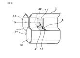
- FIG. 1 is an enlarged view of a main part of an end face of a honeycomb structure in Embodiment 1 and an axial sectional view thereof.
- FIG. 2 is an overall perspective view showing a schematic structure of a honeycomb structure in Embodiment 1.
- FIG. 3 is an enlarged perspective view of a main part of a honeycomb structure showing a schematic structure of a cell provided with a projecting piece in the first embodiment.
- FIG. 4 is an enlarged cross-sectional view of the main part in the axial direction of the honeycomb structure according to the first embodiment, showing an exhaust gas flow in the cell provided with the projecting pieces in comparison with the cell not provided with the projecting pieces.
- Figure FIG. 5 is an enlarged view of a main part showing the relationship between the height and length of the cells of the honeycomb structure and the protruding pieces in Embodiment 1.
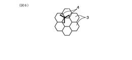
- FIG. 6 is a diagram schematically illustrating an arrangement example of cells provided with protrusions of the honeycomb structure according to the second embodiment.
- FIG. 7 is a diagram schematically illustrating an arrangement example of cells provided with the protrusions of the honeycomb structure according to the second embodiment.
- FIG. 8 is a diagram schematically illustrating an arrangement example of cells provided with protrusions of the honeycomb structure according to the second embodiment.
- FIG. 9 is a diagram schematically illustrating an arrangement example of cells provided with projecting pieces of a honeycomb structure in Embodiment 2.
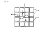
- FIG. 10 is a diagram schematically illustrating an arrangement example of cells provided with projecting pieces of a honeycomb structure in Embodiment 3.
- FIG. 11 is a diagram illustrating an optical electron microscope observation image (that is, magnification of 100 times) of the cell structure provided with the protrusions of the honeycomb structure in the example
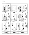
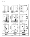
- FIG. 12 is a diagram showing the relationship between the density of the projecting pieces of the honeycomb structure and the purification performance, the pressure loss, and the isostatic strength in Examples 1 to 3.
- FIG. 13 is a diagram showing the relationship between the density of the protrusions of the honeycomb structure and the purification performance, pressure loss, and isostatic strength in Examples 4 to 6
- FIG. 14 is a diagram showing the relationship between the height of the protrusions of the honeycomb structure and the purification performance, pressure loss, and isostatic strength in Examples 7 to 9
- FIG. 15 is a diagram showing the relationship between the height of the protrusions of the honeycomb structure and the purification performance, pressure loss, and isostatic strength in Examples 10 to 12
- FIG. 16 is a diagram showing the relationship between the distance between the protrusions of the honeycomb structure and the purification performance, pressure loss, and isostatic strength in Examples 13 to 15.
- FIG. 17 is a diagram showing the relationship between the distance between the protrusions of the honeycomb structure and the purification performance, pressure loss, and isostatic strength in Examples 16 to 18.
- FIG. 18 is a diagram showing the relationship between the distance between the protrusions of the honeycomb structure and the purification performance, pressure loss, and isostatic strength in Examples 19 to 21.
- the honeycomb structure 1 includes a cylindrical outer skin 11 that opens at both ends, a cell wall 2 that defines the inside of the cylindrical outer skin 11, and a large number of cells 3 that are surrounded by the cell wall 2. It has. A large number of cells 3 are arranged in parallel to the axial direction X of the cylindrical outer skin 11 and open at both end faces of the cylindrical outer skin 11.
- the honeycomb structure 1 is used, for example, as a catalyst carrier for supporting a catalyst, and constitutes a catalyst body in which a catalyst layer (not shown) is formed on the surface of a cell wall 2 facing a large number of cells 3.
- a catalyst body is applied to an exhaust gas purification catalyst for an automobile engine, and is coaxially mounted in an exhaust gas pipe to purify the exhaust gas G from the engine.
- the honeycomb structure 1 is provided with a protruding piece 4 on a cell wall 2 surrounding the cell 3 in at least a part of the large number of cells 3.
- the projecting piece 4 is formed by a cut-and-raised piece provided on the cell wall 2, forms a through hole 41 penetrating the cell wall 2, and protrudes from the end edge of the through hole 41 in an inward direction of the cell 3.
- a protruding wall 42 is formed.
- an opening edge portion that is cut and raised constitutes an end edge portion of the through hole 41, and a protruding wall 42 that rises integrally from a part thereof.
- a large number of cells 3 are, for example, polygonal cells. In this embodiment, it is a hexagonal cell having a hexagonal cross-sectional shape, and each cell 3 is adjacent to the six cells 3 via the cell walls 2 constituting the six sides of the hexagon.
- the protruding pieces 4 are arranged in a plurality of cells 3 among a large number of cells 3, and the protruding pieces 4 are arranged in the cells 3 at intervals in the axial direction. Since the protruding piece 4 is formed by the cut and raised piece of the cell wall 2, the through hole 41 can be formed without reducing the effective area of the cell wall 2 serving as the catalyst carrier. Moreover, since the protruding wall 42 formed by the protruding piece 4 has an inclination with respect to the flow of the exhaust gas G, a dead space in which the exhaust gas G does not contact is less likely to be generated. Can be improved.
- the honeycomb structure 1 has such protruding pieces 4 at a predetermined density.
- the density per unit area of the projection pieces 4 is 1 piece / cm 2 or more on the projection surface in which the projection pieces 4 in the cells 3 are projected onto the end face 12 where a large number of cells 3 are open.
- the exhaust gas purification performance of the catalyst body can be improved.
- the density per unit area of the protrusions 4 is 2 / cm 2 to 40 cm 2 , the exhaust gas purification performance is improved while suppressing an increase in pressure loss and a decrease in strength. be able to.
- a plurality of cells 3 having one protruding piece 4 are provided on a cell wall 2 constituting one side of a hexagon, and these cells 3 are adjacent to each other to form a honeycomb structure. Distributed throughout the body 1. Specifically, the cells 3 having the protruding pieces 4 on one side are arranged so as to surround the cells 3 not having the protruding pieces 4, and the protruding pieces 4 are arranged on the entire honeycomb structure 1 in the same pattern. Distribute evenly. In this pattern, the cells 3 having the projecting pieces 4 are adjacently arranged with the sides having the projecting pieces 4 so that the three projecting pieces 4 are symmetrically located around the vertex common to the three adjacent cells 3. .
- the three cells 3 have a symmetrical shape with a common vertex as the center, and the cross-sectional areas of the internal gas passages 31 are equal. Further, as shown in the right diagram in FIG. 1, in the axial cross section passing through the common apex, the cells 3 having the protruding pieces 4 at predetermined positions are continuously arranged in a direction orthogonal to the axial direction X. And two adjacent cells 3 communicate with each other through the through hole 41. In each cell 3, a plurality of protruding pieces 4 are arranged at a predetermined distance Dt in the axial direction. The projecting piece 4 located on the most upstream side is disposed at a distance D1 (for example, Dt ⁇ D1) from the upstream end face 12.
- D1 for example, Dt ⁇ D1
- each protruding piece 4 constitutes a protruding wall 42 protruding into each cell 3 from a base end position integral with the cell wall 2, and an opening formed in the cell wall 2 by cutting and raising becomes a through hole 41.
- the projecting wall 42 has a curved shape that protrudes inward of the cell, and has an inclined shape that decreases in height toward the apex of the hexagon and decreases toward the base end position. And is arranged so as to cover the through hole 41.
- the protruding pieces 4 formed on two of the three cell walls 2 are illustrated, but the protruding pieces 4 formed on the remaining one have the same shape.
- the adjacent three cells 3 are communicated with each other via the through holes 41 at substantially the same position with respect to the common apex, and the protruding walls 42 having the same shape are symmetrically arranged in the gas passages 31 in the cells 3. Therefore, there is no pressure difference and gas flow rate difference between the three gas passages 31. Therefore, the exhaust gas G can flow between the adjacent gas passages 31, and the exhaust gas G easily flows into the through hole 41 along the inclined protruding wall 42, thereby easily coming into contact with the inner surface of the protruding wall 42. . Further, the exhaust gas G that has passed through the through hole 41 collides with the protruding wall 42 protruding into the adjacent gas passage 31 and flows downstream along the inclined outer surface. Therefore, the flow which peels off from the protrusion wall 42 or the flow which stays is eliminated, and a contact rate with the protrusion wall 42 rises.
- the boundary layer B is formed on the surface of the cell wall 2 due to the influence of the viscosity of the exhaust gas G that has flowed.
- the heat transfer rate and the mass transfer rate are lowered, so that the heat reception rate from the exhaust gas G is lowered and the contact rate with the cell wall 2 surface is lowered.
- the boundary layer B develops toward the downstream side, and eventually reaches the center and becomes the thickest. The distance until the maximum thickness is reached is called a run-up section I. In the downstream area from the run-up section I, the purification performance of the exhaust gas passing therethrough is lowered.
- the boundary layer B is destroyed. Therefore, the development of the boundary layer B can be suppressed by setting the distances D1 and Dt at which the protruding pieces 4 are disposed to be shorter than the run-up section I (that is, I ⁇ Dt ⁇ D1). In the downstream area of the projecting wall 42, the boundary layer B is formed again. However, since the boundary layer B is suppressed to a thin state, the heat transfer rate and the mass transfer rate can be maintained.
- the height H of the protruding piece 4 is the radial distance between the distal end position and the proximal end position of the protruding wall 42.
- the height H of the protruding piece 4 can be arbitrarily set, and is preferably 5 ⁇ m or more, for example.
- the thickness tc of the catalyst layer in a general exhaust gas purification catalyst is usually in the range of 5 ⁇ m to 200 ⁇ m, preferably 20 ⁇ m to 100 ⁇ m, and tends to be thinner.
- the height H of the protruding piece 4 is preferably set to be equal to or greater than the thickness tc of the catalyst layer (that is, H ⁇ tc), thereby improving the purification performance without the protruding wall being buried in the catalyst layer. it can.
- the height H of the protruding piece 4 is preferably not more than the distance Dc to the center of the cell 3.
- Dc (P ⁇ t) / 2 using the cell pitch P and the thickness t of the cell wall 2.
- the length L of the protruding piece 4 is the length from the proximal end position to the distal end position of the protruding wall 42, and the axis of the through hole 41 opening in the cell wall 2. Corresponds to the direction length.
- the length L of the protruding piece 4 is preferably set as appropriate according to the height H of the protruding piece 4, the axial distance Dt, the cell pitch P, and the like. For example, pressure loss tends to increase as the height H increases with respect to the length L of the protruding piece 4, and preferably, the length L of the protruding piece 4 is greater than or equal to the height H (that is, L ⁇ H). There should be.
- the length L of the protruding piece 4 is not more than the distance Dt / 2 (that is, Dt / 2 ⁇ L).
- the height H, the length L, and the distance Dt of the protruding pieces 4 formed in the same cell 3 or a plurality of cells 3 may be different and are not necessarily constant. Further, the arrangement of the cells 3 having the protruding pieces 4 is not limited to the pattern described above, and can be arbitrarily set. Below, the example which changed arrangement
- one protruding piece 4 is arranged symmetrically in three adjacent cells 3 and arranged so as to surround the cell 3 having no protruding piece 4.
- the number of the protrusion pieces 4 and the arrangement of the cells 3 having the protrusion pieces 4 can be appropriately changed so that the desired density is obtained.
- the protruding pieces 4 are provided only in the two cells 3 to be performed.
- the protruding pieces 4 may be provided on the two opposite sides of the central cell 3, and the protruding pieces 4 may be provided on the two cells 3 having the two sides and the apex in common. As shown in FIG. 8, protrusions 4 may be provided on three non-adjacent sides of the center cell 3, and the protrusions 4 may be provided on two cells 3 having the three sides and the vertex in common. In the example shown in FIG. 8, one protruding piece 4 is formed in all the cells 3 surrounding the central cell 3.
- a protruding piece 4 may be provided on one side of the central cell 3, and the protruding piece 4 may be provided on each of the three cells 3 that share three consecutive sides including the one side. At this time, the same effect can be obtained by arranging the protruding pieces 4 having the same shape around the common vertex. Further, since the protruding pieces 4 are not arranged in the center cell 3 in an uneven manner, it is easy to suppress an increase in pressure loss.
- the honeycomb structure 1 includes a large number of cells 3 formed of hexagonal cells, but the shape of the cells 3 is arbitrary and can be changed as appropriate.
- the honeycomb structure 1 is composed of a large number of cells 3 and quadrangular cells, and one protruding piece 4 is symmetrically arranged around a vertex common to four adjacent cells 3. May be.
- the cells 3 that do not have the protruding pieces 4 are arranged so as to surround these cells 3.
- a plurality of protruding pieces 4 may be arranged in one cell 3, or the protruding pieces 4 are arranged in the surrounding cells 3 surrounding the central four cells 3. May be.
- the honeycomb structure 1 having the above configuration is made of a ceramic material and can be manufactured by the following method.
- the ceramic raw material is not particularly limited, and for example, a plurality of ceramic raw materials to be cordierite, silicon carbide, mullite, alumina, spinel, aluminum titanate and the like are used.
- the ceramic material is cordierite, and it is preferable to use a plurality of ceramic raw materials to be cordierite.
- a plurality of ceramic raw materials to be cordierite are raw materials such as talc, kaolin, calcined kaolin, alumina, aluminum hydroxide, silica, magnesium hydroxide, etc.
- a ceramic raw material containing alumina and silica is mixed at a ratio such that a known cordierite composition is obtained.
- a molding material is prepared by kneading a molding material in which a binder, a surfactant, water and the like are mixed with such a ceramic raw material.
- the binder include methyl cellulose, hydroxypropyl methyl cellulose, hydroxyethyl cellulose, carboxymethyl cellulose, and the like, and methyl cellulose and hydroxypropyl methyl cellulose are particularly preferable.
- a binder may use several types together.
- the binder content is preferably 3 to 15 parts by mass with respect to 100 parts by mass of the ceramic raw material.
- the surfactant include fatty acid esters and fatty acid soaps, and the content is preferably 1 part by mass to 5 parts by mass with respect to 100 parts by mass of the ceramic raw material.
- the water content is preferably 23 to 32 parts by mass with respect to 100 parts by mass of the ceramic raw material.
- the kneading method is not particularly limited, but a kneader, a vacuum screw kneader or the like can be used.
- the obtained clay is formed into a honeycomb to form a formed body.
- a mold having a desired cell shape, cell wall thickness, cell density, and cell pitch is used, and the clay prepared as described above is extruded.
- a method of controlling the clay flow at the time of forming is used, or the formed body is processed using an apparatus having a needle-like processing blade or the like. There is a way to do it. From the viewpoint of productivity, a method of controlling the dredging flow is preferable. Specifically, a plate or a net for controlling the amount of dredging is installed on the dredging side of the mold, or the dredging of the mold is performed. A method of installing a structure having a protrusion shape or a structure for controlling flow on the soil discharge side can be mentioned.
- the honeycomb structure 1 is formed by, for example, firing at 1400 ° C. to form cordierite. Further, when the honeycomb structure 1 is used as a catalyst carrier, the honeycomb structure 1 is immersed in a catalyst solution containing a noble metal catalyst and heat-treated. Thereby, it can be set as the catalyst body which formed the catalyst layer.
- the honeycomb structure 1 made of cordierite was manufactured by the above-described method, and a catalyst layer made of noble metal was formed to obtain a catalyst body.
- ceramic raw materials such as talc, kaolin, alumina, aluminum hydroxide and the like were mixed at a ratio that would give a cordierite composition to obtain a cordierite forming raw material.
- a binder such as methyl cellulose, a surfactant such as fatty acid ester, and water are mixed and kneaded in the above-mentioned range to form clay, extruded, and formed into a honeycomb structure. It was.
- the size of the honeycomb structure 1 was, for example, a diameter ⁇ : 100 mm and a length L: 100 mm.
- the honeycomb structures 1 of Examples 1 to 6 have a cell structure having a cell thickness of 50 ⁇ m to 150 ⁇ m (that is, 2 mil to 6 mil) and a cell density of 400 cps to 1200 cps (that is, 62 cells). / Cm 2 to 186 / cm 2 ).
- the density per unit area of the protruding pieces 4 was changed within the range of 0.2 / cm 2 to 50 / cm 2 . Examples 1-1 to 1-7 were used.
- the cell 3 of the honeycomb structure 1 has a hexagonal cross-sectional shape.
- the cell pitch P is 1100 ⁇ m
- the length L of the projection piece 4 is 0.45 mm
- the height H is 200 ⁇ m
- the distance D is 4 mm.
- Example 1 and Comparative Example 1 The catalyst bodies obtained in Example 1 and Comparative Example 1 were subjected to a purification performance test using a model gas, and the effects on the purification performance, pressure loss, and isostatic strength were examined.
- the cell 3 had a wall thickness of 88 ⁇ m (that is, 3.5 mil) and a cell density of 600 cps (that is, 93 cells / cm 2 ).
- the purification performance and pressure loss were evaluated by relative values when the result of Comparative Example 1 was 1.
- the isostatic strength was expressed by a pressure value (unit: MPa) when the honeycomb structure 1 was broken by performing an isostatic strength test by a method defined in JASO M 505-87.
- the purification performance is improved by forming the protruding pieces 4 as compared with Comparative Example 1 as in Examples 1-1 to 1-7.
- the density of the protrusions 4 that is, the protrusion density in the figure
- strength No deterioration is observed.
- the purification performance improves without deteriorating the pressure loss and strength, but as the density increases, the pressure loss increases and the strength decreases.
- Examples 2-1 to 2-5 and Comparative Example 2 in which the honeycomb structure 1 was a thin wall (that is, the wall thickness was 50 ⁇ m).
- Example 4 in Examples 4-1 to 4-5 and Comparative Example 4 in which the cell density of the honeycomb structure 1 was increased (that is, 1200 cps; 186 cells / cm 2 ), the same There was a trend.
- the purification performance is further improved because the cell density is increased and the distance Dc to the cell center is shorter than before the cell density is increased. An increase in pressure loss is also observed.
- Example 6- in which the cell density was increased and the cell wall thickness was decreased 1 to 6-5 and Comparative Example 6 (that is, wall thickness 50 ⁇ m, cell density 400 cps; 62 cells / cm 2 ) were the same.
- Examples 7 to 12 As shown in Table 3, a honeycomb structure 1 in which the height H of the projecting piece 4 was changed in the range of 25 ⁇ m to 700 ⁇ m was manufactured in the same manner as in Examples 1 to 6. In each of the honeycomb structures 1, the density of the protruding pieces 4 was 2.0 pieces / cm 2 . As in Examples 1 to 6, the wall thickness and cell density were changed, and Examples 7-1 to 7-8, Examples 8-1 to 8-5, Examples 9-1 to 9-5, The honeycomb structures 1 of Examples 10-1 to 10-4, Examples 11-1 to 11-4, and Examples 12-1 to 12-5 were formed, and a catalyst layer was formed on each of these honeycomb structures 1. A catalyst body was obtained.
- Table 3 shows the results of examining the effects on purification performance, pressure loss, and isostatic strength.
- Examples 8-1 to 8-5 that is, the wall thickness of 50 ⁇ m in which the honeycomb structure 1 was a thin wall
- Examples 9-1 to 9-5 in which the honeycomb structure 1 was a thick wall that is, a wall thickness of 150 ⁇ m
- the same tendency was observed with respect to the distance Dc below for Examples 10 to 12 in which the cell pitch P was increased or decreased by changing the cell density.
- the height H of the protruding piece 4 is set to be not less than the thickness tc of the catalyst layer, preferably not less than half of the distance Dc, and not more than the distance Dc. Is preferred.
- Examples 13 to 18 In the same manner as in Examples 1 to 6, as shown in Table 4, a honeycomb structure 1 was manufactured in which the distance D between the projecting pieces 4 was changed in the range of 1 ⁇ m to 20 ⁇ m. In each of the honeycomb structures 1, the height of the protruding pieces 4 was 200 ⁇ m, and the density of the protruding pieces 4 was 1.0 piece / cm 2 to 2.0 pieces / cm 2 .
- Example 1 to 6 the wall thickness and cell density were changed, and Examples 13-1 to 13-5, Examples 14-1 to 14-5, Examples 15-1 to 15-5, The honeycomb structures 1 of Examples 16-1 to 16-5, Examples 17-1 to 17-5, and Examples 18-1 to 18-5 were formed, and a catalyst layer was formed on each of these honeycomb structures 1. A catalyst body was obtained. Similarly, Table 4 shows the results of examining the effects on purification performance, pressure loss, and strength.
- the distance D of the protruding piece 4 is set to be not less than twice the length L, preferably in the range of 2 mm to 20 mm.
- Examples 19 to 21 In the same manner as in Example 1, as shown in Table 5, a honeycomb structure 1 in which the length L was changed with respect to the height H of the protruding piece 4 was manufactured.
- the honeycomb structures 1 each had a wall thickness of 88 ⁇ m, a cell density of 600 cps, the density of the projecting pieces 4 was 2.0 pieces / cm 2 , and the height of the projecting pieces 4 was 200 ⁇ m to 400 ⁇ m.
- Example 5 shows the results of examining the effects on purification performance, pressure loss, and strength.
- the length L is longer than the height H of the protrusion 4 and the length L is longer than 1 ⁇ 2 of the distance D (that is, L ⁇ H, L ⁇ D / 2). ), Preferably set.
- the cell shape of the honeycomb structure 1 can be an arbitrary shape such as a polygon other than a square or a hexagon, or a circle. A plurality of cell shapes or cell shapes having different sizes may be combined.
- the said embodiment demonstrated as an application example to the exhaust gas purification catalyst for motor vehicles it can use arbitrarily for various uses, such as not only a motor vehicle engine but the catalyst body which purify
Landscapes
- Chemical & Material Sciences (AREA)
- Engineering & Computer Science (AREA)
- Chemical Kinetics & Catalysis (AREA)
- Combustion & Propulsion (AREA)
- Health & Medical Sciences (AREA)
- General Engineering & Computer Science (AREA)
- Mechanical Engineering (AREA)
- Toxicology (AREA)
- Ceramic Engineering (AREA)
- Biomedical Technology (AREA)
- Environmental & Geological Engineering (AREA)
- Analytical Chemistry (AREA)
- General Chemical & Material Sciences (AREA)
- Oil, Petroleum & Natural Gas (AREA)
- Organic Chemistry (AREA)
- Materials Engineering (AREA)
- Exhaust Gas Treatment By Means Of Catalyst (AREA)
- Catalysts (AREA)
- Exhaust Gas After Treatment (AREA)
- Porous Artificial Stone Or Porous Ceramic Products (AREA)
Abstract
ハニカム構造体(1)は、両端開口の筒状外皮(11)内を区画するセル壁(2)と、該セル壁に囲まれ、上記筒状外皮の軸方向Xに平行配設される多数のセル(3)と、を備えている。上記多数のセルのうち少なくとも一部の上記セルには、突起片(4)が設けられており、上記突起片によって、上記セル壁を貫通する通孔(41)と、該通孔の端縁部から上記セルの内方に傾斜して突き出す突壁(42)と、が構成されている。
Description
本出願は、2016年1月21日に出願された特許出願番号2016-009838号に基づくもので、その特許出願のすべての内容が、参照により本明細書に組み入れられる。
本開示は、排ガス浄化触媒等に用いられるハニカム構造体及び触媒体に関する。
自動車等の排ガス管に取り付けられる排ガス浄化触媒は、排ガス流れに平行な多数のセルを有するハニカム構造体と、多数のセルを区画するセル壁の表面に形成される触媒層とからなる。ハニカム構造体の一端側から流入する排ガスは、多数のセル内を通過する間に、セル壁の触媒層と接触して浄化される。
排ガス浄化触媒による浄化性能を高めるために、排ガスと触媒層との接触面積を大きくする構造が検討されている。例えば、特許文献1には、ハニカム構造体のセル壁を表面に凹凸を有する形状として、セル壁の表面積を向上させた触媒体が開示されている。また、排ガスの通過を妨げるように突起部を形成したり、セル壁を湾曲させたりすることで、排ガスがセル壁と衝突する構成としたものがある。また、ハニカム構造体のセル内に流入する排ガス流れが、下流に進むにつれてセル壁の近傍に境界層を形成することが知られており、例えば、セル壁に形成した空孔や凹凸によって、乱流を生成するようにしたものがある。
ハニカム構造体において、セル壁に突起部を形成した場合は、セル内の排ガスの通過断面積が減るために、圧力損失の増大を免れない。また、突起部の後流側にガス流れの停滞や剥離が生じて、セル壁の触媒層を活用できない部分が生じやすい。一方、セル壁に空孔を形成した場合には、強度の低下につながり、接触面積が減少するだけでなく、空孔を介して排ガスの流通が十分になされないと、浄化性能の向上効果が得られない。例えば、突起部と空孔を組み合わせた場合は、突起部を有するセルの圧力損失が他のセルより増大するために、排ガスが流れにくくなり、突起部のないセルに排ガス流れが偏る。そのために、突起部を有するセルの排ガス流量が低下すると、触媒層が有効に活用されず、突起部の形成による効果が得られない、といった課題が見出された。
本開示の目的は、多数のセル内のガス流れが偏らず、圧力損失の上昇や強度低下を抑制しながら、ガス流れと接触するセル壁の面積を増加させることのできるハニカム構造体を提供すること、さらに、このようなハニカム構造体を用いて触媒との接触率を高め、浄化性能を向上できる触媒体を提供しようとするものである。
本開示の一態様は、
両端開口の筒状外皮内を区画するセル壁と、
該セル壁に囲まれ、上記筒状外皮の軸方向に平行配設される多数のセルと、を備える、ハニカム構造体であって、
該多数のセルのうち少なくとも一部の上記セルには、上記セル壁を貫通する通孔と、該通孔の端縁部から上記セルの内方に傾斜して突き出す突壁と、を構成する突起片が設けられる、ハニカム構造体にある。
両端開口の筒状外皮内を区画するセル壁と、
該セル壁に囲まれ、上記筒状外皮の軸方向に平行配設される多数のセルと、を備える、ハニカム構造体であって、
該多数のセルのうち少なくとも一部の上記セルには、上記セル壁を貫通する通孔と、該通孔の端縁部から上記セルの内方に傾斜して突き出す突壁と、を構成する突起片が設けられる、ハニカム構造体にある。
本開示の他の態様は、ハニカム構造体に触媒を担持してなる触媒体であって、
上記ハニカム構造体は、
両端開口の筒状外皮内を区画するセル壁と、
該セル壁に囲まれ、上記筒状外皮の軸方向に平行配設される多数のセルと、を備えており、
該多数のセルのうち少なくとも一部の上記セルには、上記セル壁を貫通する通孔と、該通孔の端縁部から上記セルの内方に傾斜して突き出す突壁と、を構成する突起片が設けられる、触媒体にある。
上記ハニカム構造体は、
両端開口の筒状外皮内を区画するセル壁と、
該セル壁に囲まれ、上記筒状外皮の軸方向に平行配設される多数のセルと、を備えており、
該多数のセルのうち少なくとも一部の上記セルには、上記セル壁を貫通する通孔と、該通孔の端縁部から上記セルの内方に傾斜して突き出す突壁と、を構成する突起片が設けられる、触媒体にある。
上記態様のハニカム構造体は、多数のセルの少なくとも一部のセルに突起片が設けられるので、セル壁に開口する通孔により、隣り合うセル間が通気可能となると共に、通孔に続く傾斜する突壁により、隣り合うセル内へのガス流入が促されて圧力差が緩和される。また、突起片は、セル壁の表面積を減少させることがなく、強度の低下が抑制される。さらに、突壁によって、セル壁の近傍のガス流れが乱されるので、境界層の形成が抑制され、ガス流れとセル壁とが接触しやすくなる。
したがって、ハニカム構造体を、排ガス浄化触媒に適用した場合には、多数のセルの全体に排ガスを流入させて、セル壁の表面に形成される触媒層と排ガスとの接触率を高めることができ、排ガスの浄化性能を向上させることができる。
本開示についての上記目的及びその他の目的、特徴や利点は、添付の図面を参照しながら下記の詳細な記述により、より明確になる。その図面は、
図1は、実施形態1における、ハニカム構造体の端面における要部拡大図とその軸方向断面図であり、
図2は、実施形態1における、ハニカム構造体の概略構造を示す全体斜視図であり、
図3は、実施形態1における、突起片を設けたセルの概略構造を示すハニカム構造体の要部拡大斜視図であり、
図4は、実施形態1における、ハニカム構造体の軸方向の要部拡大断面図で、突起片を設けたセル内の排ガス流れを、突起片を設けないセルと比較して示す要部拡大断面図であり、
図5は、実施形態1における、ハニカム構造体のセルと突起片の高さ及び長さの関係を示す要部拡大図であり、
図6は、実施形態2における、ハニカム構造体の突起片を設けたセルの配置例を模式的に示す図であり、
図7は、実施形態2における、ハニカム構造体の突起片を設けたセルの配置例を模式的に示す図であり、
図8は、実施形態2における、ハニカム構造体の突起片を設けたセルの配置例を模式的に示す図であり、
図9は、実施形態2における、ハニカム構造体の突起片を設けたセルの配置例を模式的に示す図であり、
図10は、実施形態3における、ハニカム構造体の突起片を設けたセルの配置例を模式的に示す図であり、
図11は、実施例における、ハニカム構造体の突起片を設けたセル構造の光学電子顕微鏡観察像(すなわち、倍率100倍)を示す図であり、
図12は、実施例1~3における、ハニカム構造体の突起片の密度と浄化性能、圧力損失及びアイソスタティック強度との関係を示す図であり、
図13は、実施例4~6における、ハニカム構造体の突起片の密度と浄化性能、圧力損失及びアイソスタティック強度との関係を示す図であり、
図14は、実施例7~9における、ハニカム構造体の突起片の高さと浄化性能、圧力損失及びアイソスタティック強度との関係を示す図であり、
図15は、実施例10~12における、ハニカム構造体の突起片の高さと浄化性能、圧力損失及びアイソスタティック強度との関係を示す図であり、
図16は、実施例13~15における、ハニカム構造体の突起片間の距離と浄化性能、圧力損失及びアイソスタティック強度との関係を示す図であり、
図17は、実施例16~18における、ハニカム構造体の突起片間の距離と浄化性能、圧力損失及びアイソスタティック強度との関係を示す図であり、
図18は、実施例19~21における、ハニカム構造体の突起片間の距離と浄化性能、圧力損失及びアイソスタティック強度との関係を示す図である。
(実施形態1)
ハニカム構造体に係る実施形態1について、図面を参照しながら説明する。図1、図2に示すように、ハニカム構造体1は、両端が開口する筒状外皮11と、筒状外皮11内を区画するセル壁2と、セル壁2に囲まれる多数のセル3とを備えている。多数のセル3は、筒状外皮11の軸方向Xに平行配設され、筒状外皮11の両端面に開口する。ハニカム構造体1は、例えば、触媒を担持させるための触媒担体として用いられ、多数のセル3に面するセル壁2の表面に、図示しない触媒層を形成した触媒体を構成する。このような触媒体は、自動車エンジン用の排ガス浄化触媒等に適用されて、排ガス管内に同軸的に取り付けられ、エンジンからの排ガスGを浄化する。
ハニカム構造体に係る実施形態1について、図面を参照しながら説明する。図1、図2に示すように、ハニカム構造体1は、両端が開口する筒状外皮11と、筒状外皮11内を区画するセル壁2と、セル壁2に囲まれる多数のセル3とを備えている。多数のセル3は、筒状外皮11の軸方向Xに平行配設され、筒状外皮11の両端面に開口する。ハニカム構造体1は、例えば、触媒を担持させるための触媒担体として用いられ、多数のセル3に面するセル壁2の表面に、図示しない触媒層を形成した触媒体を構成する。このような触媒体は、自動車エンジン用の排ガス浄化触媒等に適用されて、排ガス管内に同軸的に取り付けられ、エンジンからの排ガスGを浄化する。
図1に示すように、ハニカム構造体1は、多数のセル3のうち少なくとも一部において、セル3を取り囲むセル壁2に、突起片4を設けている。突起片4は、セル壁2に設けた切起し片からなり、セル壁2を貫通する通孔41を形成すると共に、通孔41の端縁部からセル3の内方に傾斜して突き出す突壁42を形成する。突起片4は、切起しされた開口縁部が、通孔41の端縁部を構成し、その一部から一体的に立ち上がる突壁42を構成している。多数のセル3は、例えば、多角形セルからなる。本形態では、六角形の断面形状を有する六角形セルであり、各セル3は、六角形の6つの辺を構成するセル壁2を介して、6つのセル3と隣り合う。
ハニカム構造体1の多数のセル3内には、排ガスG流れの上流側に位置する端面12(例えば、図2の左端面)から、下流側の端面13(例えば、図2の右端面)に至る、多数のガス通路31が形成される。突起片4により形成される突壁42は、その先端側が、排ガスG流れの上流側を向くように、セル壁2に対して傾斜を有して立ち上がる。このとき、突起片4を有するセル3に流入する排ガスGは、突起片4の基端側に開口する通孔41を介して、隣り合うセル3内のガス通路31に流入可能となる。
本形態のハニカム構造体1は、多数のセル3のうち複数のセル3に突起片4を配置し、各セル3内に、複数の突起片4を軸方向に間隔をおいて配置する。突起片4は、セル壁2の切起し片にて形成されるので、触媒担体となるセル壁2の有効面積を減らすことなく、通孔41を形成することができる。また、突起片4により形成される突壁42は、排ガスG流れに対して傾斜を有するので、排ガスGが接触しないデッドスペースが生じにくく、その両面を有効利用して、排ガスとの接触率を向上させることができる。
ハニカム構造体1は、このような突起片4を、所定の密度で有する。具体的には、多数のセル3が開口する端面12に、セル3内の突起片4を投影した投影面において、突起片4の単位面積当たりの密度が、1個/cm2以上となるように配置することで、触媒層を形成したときに、触媒体の排ガス浄化性能を向上させることができる。好適には、突起片4の単位面積当たりの密度が、2個/cm2~40個cm2の密度となるように配置すると、圧損増加と強度低下を抑制しながら、排ガス浄化性能を向上することができる。
図1中の左図に示す配置例においては、六角形の1つの辺を構成するセル壁2に、1つの突起片4を有するセル3を複数設け、これらセル3を隣接させて、ハニカム構造体1の全体に分散配置している。具体的には、1つの辺に突起片4を有するセル3が、突起片4を有しないセル3の周りを取り囲むように配置し、同様のパターンでハニカム構造体1の全体に突起片4を均等に配置する。このパターンでは、突起片4を有するセル3は、隣り合う3つのセル3に共通の頂点を中心に、3つの突起片4が対称位置するように、突起片4を有する辺が隣接配置される。
このとき、3つのセル3は、共通の頂点を中心にした対称形状となり、内部のガス通路31の断面積は同等となる。また、図1中の右図に示すように、共通の頂点を通る軸方向断面においては、所定位置に突起片4を有するセル3が、軸方向Xと直交する方向に、連続して規則的に並び、通孔41を介して隣り合う2つのセル3間が連通している。各セル3内には、複数の突起片4が、軸方向に所定の距離Dtをおいて配置される。最上流に位置する突起片4は、上流側の端面12から距離D1(例えば、Dt≧D1)の位置に配置される。
図3に示すように、共通の頂点を有する3つのセル3において、隣り合う3つのセル壁2には、軸方向の略同等位置を切り起こして、それぞれ突起片4が形成されている。各突起片4は、セル壁2と一体の基端位置から各セル3内に突き出す突壁42を構成し、切り起こしによりセル壁2に形成される開口部は、通孔41となる。ここでは、突壁42は、セル内方に凸となる湾曲形状を有して、六角形の頂点に近い側で高さが低くなり、また基端位置へ向けて高さが低くなる傾斜形状を有して、通孔41を覆うように配置されている。なお、図3中には、3つのセル壁2のうちの2つに形成した突起片4を図示しているが、残る1つに形成される突起片4も同様の形状とする。
このように、隣り合う3つのセル3を、共通の頂点に対して略同等位置にある通孔41を介して互いに連通させ、セル3内のガス通路31に同形状の突壁42を対称配置したので、3つのガス通路31の間に圧力差、ガス流量差は生じなくなる。そのため、隣り合うガス通路31間を排ガスGが流通可能となり、また、排ガスGが、傾斜する突壁42に沿って通孔41に流入することにより、突壁42の内表面と接触しやすくなる。さらに、通孔41を通過した排ガスGは、隣り合うガス通路31内に突き出す突壁42に衝突し、その傾斜する外表面に沿って、下流へ流れる。したがって、突壁42から剥がれる流れや滞留する流れをなくし、突壁42との接触率が上昇する。
また、図4に示すように、突起片4を有しないセル3では、流入した排ガスGの粘性の影響により、セル壁2の表面に境界層Bが形成される。境界層B内では、熱伝達率と物質伝達率が低下するため、排ガスGからの受熱率が低下すると共に、セル壁2表面との接触率が低下する。この境界層Bは、下流側へ向かうほど発達し、やがて中心部に達して最も厚くなる。この最大厚さに達するまでの距離を、助走区間Iといい、助走区間Iより下流域では、通過する排ガスの浄化性能が低下する。
これに対して、突起片4を有するセル3では、セル3内のガス通路31に、突壁42の周辺に乱流が形成され、境界層Bが破壊される。したがって、突起片4が配置される距離D1、Dtを、助走区間Iよりも短く設定することで(すなわち、I≧Dt≧D1)、境界層Bの発達を抑制することができる。突壁42の下流域では、再び境界層Bが形成されるが、境界層Bが薄い状態に抑えられるので、熱伝達率と物質伝達率を維持できる。
図5中に示すセル3の径方向断面において、突起片4の高さHは、突壁42の先端位置と基端位置との径方向距離である。突起片4の高さHは、任意に設定することができ、例えば、5μm以上であるとよい。好適には、セル壁2の表面に形成される触媒層の厚さtcに応じて設定することが望ましい。一般的な排ガス浄化触媒における触媒層の厚さtcは、通常は5μm~200μm、好ましくは、20μm~100μmの範囲であり、より薄壁化する傾向にある。そこで、突起片4の高さHを、好適には、触媒層の厚さtc以上とすることで(すなわち、H≧tc)、触媒層に突壁が埋もれることなく、浄化性能を高めることができる。
また、高さHが高くなると、突壁42の先端がセル3の中心に近づき、圧力損失が増加する。そのため、突起片4の高さHは、セル3の中心までの距離Dc以下であるとよい。なお、セル3の中心までの距離Dcは、セルピッチP、セル壁2の厚さtを用いて、Dc=(P-t)/2で表される。好ましくは、Dc≧H≧Dc/2の範囲となるように設定することで、圧力損失の増加を抑制しながら、突壁42による浄化性能の向上効果を得ることができる。
図5中に示すセル3の軸方向断面において、突起片4の長さLは、突壁42の基端位置から先端位置までの長さであり、セル壁2に開口する通孔41の軸方向長に相当する。突起片4の長さLは、突起片4の高さHや軸方向の距離Dt、セルピッチP等に応じて、適宜設定するのがよい。例えば、突起片4の長さLに対して、高さHが高くなると圧力損失が増加しやすいので、好ましくは、突起片4の長さLが高さH以上(すなわち、L≧H)であるとよい。また、突起片4の長さLが、大きくなると強度が低下しやすいので、距離DtやセルピッチPよりも小さくするとよい(すなわち、Dt≧L、P≧L)。好ましくは、突起片4の長さLが、距離Dt/2以下(すなわち、Dt/2≧L)であるとよい。
なお、同一のセル3又は複数のセル3内に形成される突起片4の高さH、長さL、距離Dtは、異なっていてもよく、一定とする必要は必ずしもない。また、突起片4を有するセル3の配置は、上記したパターンに限らず、任意に設定することができる。以下に、突起片4の配置を変更した例を示す。なお、実施形態2以下において、実施形態1と同じ符号は、同じ構成を示している。
(実施形態2)
実施形態1では、図1に示したように、隣り合う3つのセル3に1つの突起片4を対称配置して、突起片4を有しないセル3を取り巻くように配置したが、突起片4が所望の密度となるように、突起片4を有するセル3の配置や突起片4の数を適宜変更することができる。例えば、図6に示す例では、突起片4を設けたセル3を中心にして、これを取り巻く6つのセルを配置したとき、中心のセル3の突起片4を設けた一辺と頂点を共通にする2つのセル3にのみ突起片4を設けている。
実施形態1では、図1に示したように、隣り合う3つのセル3に1つの突起片4を対称配置して、突起片4を有しないセル3を取り巻くように配置したが、突起片4が所望の密度となるように、突起片4を有するセル3の配置や突起片4の数を適宜変更することができる。例えば、図6に示す例では、突起片4を設けたセル3を中心にして、これを取り巻く6つのセルを配置したとき、中心のセル3の突起片4を設けた一辺と頂点を共通にする2つのセル3にのみ突起片4を設けている。
図7に示すように、中心のセル3の対向する二辺にそれぞれ突起片4を設け、これら二辺と頂点を共通にする2つのセル3にそれぞれ突起片4を設けてもよい。図8に示すように、中心のセル3の隣接しない三辺にそれぞれ突起片4を設け、これら三辺と頂点を共通にする2つのセル3にそれぞれ突起片4を設けてもよい。図8に示す例では、中心のセル3を取り巻くすべてのセル3に1つの突起片4が形成される。
図9に示すように、中心のセル3の一辺に突起片4を設け、この一辺を含む連続する三辺を共通にする3つのセル3にそれぞれ突起片4を設けてもよい。このときも、共通する頂点を中心に同等形状の突起片4が配置されることで、同様の効果が得られる。また、中心のセル3に突起片4が偏って配置されないので、圧力損失の上昇を抑制しやすい。
(実施形態3)
上記実施形態1、2では、ハニカム構造体1を多数のセル3を、六角形セルにて構成したが、セル3の形状は任意であり、適宜変更することができる。例えば、図10に示すように、ハニカム構造体1を多数のセル3を、四角形セルにて構成し、隣り合う4つのセル3に共通の頂点を中心に、1つの突起片4を対称配置してもよい。隣り合う4つのセル3の周囲には、例えば、これらセル3を取り巻くように、突起片4を有しないセル3が配置される。あるいは、上記実施形態2のように、1つのセル3に複数の突起片4を配置してもよいし、中央の4つのセル3を取り巻く周囲のセル3に突起片4を配置する構成であってもよい。
上記実施形態1、2では、ハニカム構造体1を多数のセル3を、六角形セルにて構成したが、セル3の形状は任意であり、適宜変更することができる。例えば、図10に示すように、ハニカム構造体1を多数のセル3を、四角形セルにて構成し、隣り合う4つのセル3に共通の頂点を中心に、1つの突起片4を対称配置してもよい。隣り合う4つのセル3の周囲には、例えば、これらセル3を取り巻くように、突起片4を有しないセル3が配置される。あるいは、上記実施形態2のように、1つのセル3に複数の突起片4を配置してもよいし、中央の4つのセル3を取り巻く周囲のセル3に突起片4を配置する構成であってもよい。
上記構成を有するハニカム構造体1は、セラミック材料からなり、以下の方法で製造することができる。セラミック原料は、特に制限されず、例えば、コージェライトとなる複数のセラミック原料、炭化ケイ素、ムライト、アルミナ、スピネル、チタン酸アルミニウム等が使用される。特に、セラミック材料がコージェライトであり、コージェライトとなる複数のセラミック原料を用いることが好ましい。コージェライトとなる複数のセラミック原料は、タルク、カオリン、仮焼カオリン、アルミナ、水酸化アルミニウム、シリカ、水酸化マグネシウム等、焼成によってセラミック原料同士が反応し、コージェライトになる原料系であり、マグネシア、アルミナ、シリカを含むセラミック原料を、公知のコージェライト組成になるような割合で混合した原料である。
このようなセラミック原料に、バインダ、界面活性剤、水等を混合した成形材料を混練して坏土を調製する。バインダは、例えば、メチルセルロース、ヒドロキシプロピルメチルセルロース、ヒドロキシエチルセルロース、カルボキシメチルセルロース等があり、特に、メチルセルロース、ヒドロキシプロピルメチルセルロースが好ましい。バインダは、複数の種類を併用してもよい。バインダの含有率は、セラミック原料100質量部に対して、3~15質量部が好ましい。界面活性剤は、脂肪酸エステル、脂肪酸石鹸等が挙げられ、含有率は、セラミック原料100質量部に対して、1質量部~5質量部が好ましい。水の含有率は、セラミック原料100質量部に対して、23質量部~32質量部が好ましい。混練の方法は、特に制限はないが、ニーダ―や真空スクリュー混練機等を用いることができる。
得られた坏土は、ハニカム状に成形されて、成形体となる。成形には、所望のセル形状、セル壁厚さ、セル密度、セルピッチとなる構造を有する金型を用い、上記のようにして調製した坏土の押出成形を行う。ハニカム成形体に、突起片4を形成する方法としては、成形時に坏土流れを制御して形成する方法や、成形後の成形体に、針状の加工刃等を有する装置を用いて加工を行う方法がある。生産性の観点からは、坏土流れを制御する方法が好ましく、具体的には、金型の坏土供給側に坏土の供給量を制御する板や網を設置するか、金型の坏土排出側に突起形状を有する構造や流れを制御する構造を設置する方法が挙げられる。
次いで、ハニカム成形体を乾燥させた後、例えば、1400℃で焼成して、コージェライト化させることにより、ハニカム構造体1とする。さらに、ハニカム構造体1を触媒担体とする場合には、貴金属触媒等を含む触媒溶液にハニカム構造体1を浸漬し、熱処理する。これにより、触媒層を形成した触媒体とすることができる。
(実施例1~6、比較例1~6)
上記した方法により、コージェライトからなるハニカム構造体1を製造し、貴金属からなる触媒層を形成して触媒体とした。まず、タルク、カオリン、アルミナ、水酸化アルミニウム等のセラミック原料を、コージェライト組成になるような割合で混合してコージェライト化原料を得た。このコージェライト化原料に、メチルセルロース等のバインダと、脂肪酸エステル等の界面活性剤と、水とを、上記した範囲で混合、混錬して坏土とし、押出成形して、ハニカム構造の成形体とした。押出成形時の坏土流れを調整して、形成される突起片4の密度、長さL、高さH、距離Dを変更したハニカム成形体を得た。乾燥させた後、1400℃で焼成して、ハニカム構造体1とした。なお、ハニカム構造体1の端面12から突起片4までの距離D1と、突起片4間の距離Dtは、ここでは、いずれも距離Dとした(すなわち、D=D1=Dt)。
上記した方法により、コージェライトからなるハニカム構造体1を製造し、貴金属からなる触媒層を形成して触媒体とした。まず、タルク、カオリン、アルミナ、水酸化アルミニウム等のセラミック原料を、コージェライト組成になるような割合で混合してコージェライト化原料を得た。このコージェライト化原料に、メチルセルロース等のバインダと、脂肪酸エステル等の界面活性剤と、水とを、上記した範囲で混合、混錬して坏土とし、押出成形して、ハニカム構造の成形体とした。押出成形時の坏土流れを調整して、形成される突起片4の密度、長さL、高さH、距離Dを変更したハニカム成形体を得た。乾燥させた後、1400℃で焼成して、ハニカム構造体1とした。なお、ハニカム構造体1の端面12から突起片4までの距離D1と、突起片4間の距離Dtは、ここでは、いずれも距離Dとした(すなわち、D=D1=Dt)。
ハニカム構造体1のサイズは、例えば、直径φ:100mm、長さL:100mmとした。表1に示すように、実施例1~6のハニカム構造体1は、セル構造としてセル3の壁厚を50μm~150μm(すなわち、2mil~6mil)、セル密度を400cps~1200cps(すなわち、62個/cm2~186個/cm2)の範囲を変更したものである。実施例1のハニカム構造体1について、表2に示すように、突起片4の単位面積当たりの密度を、0.2個/cm2~50個/cm2)の範囲を変更したものを、実施例1-1~1-7とした。

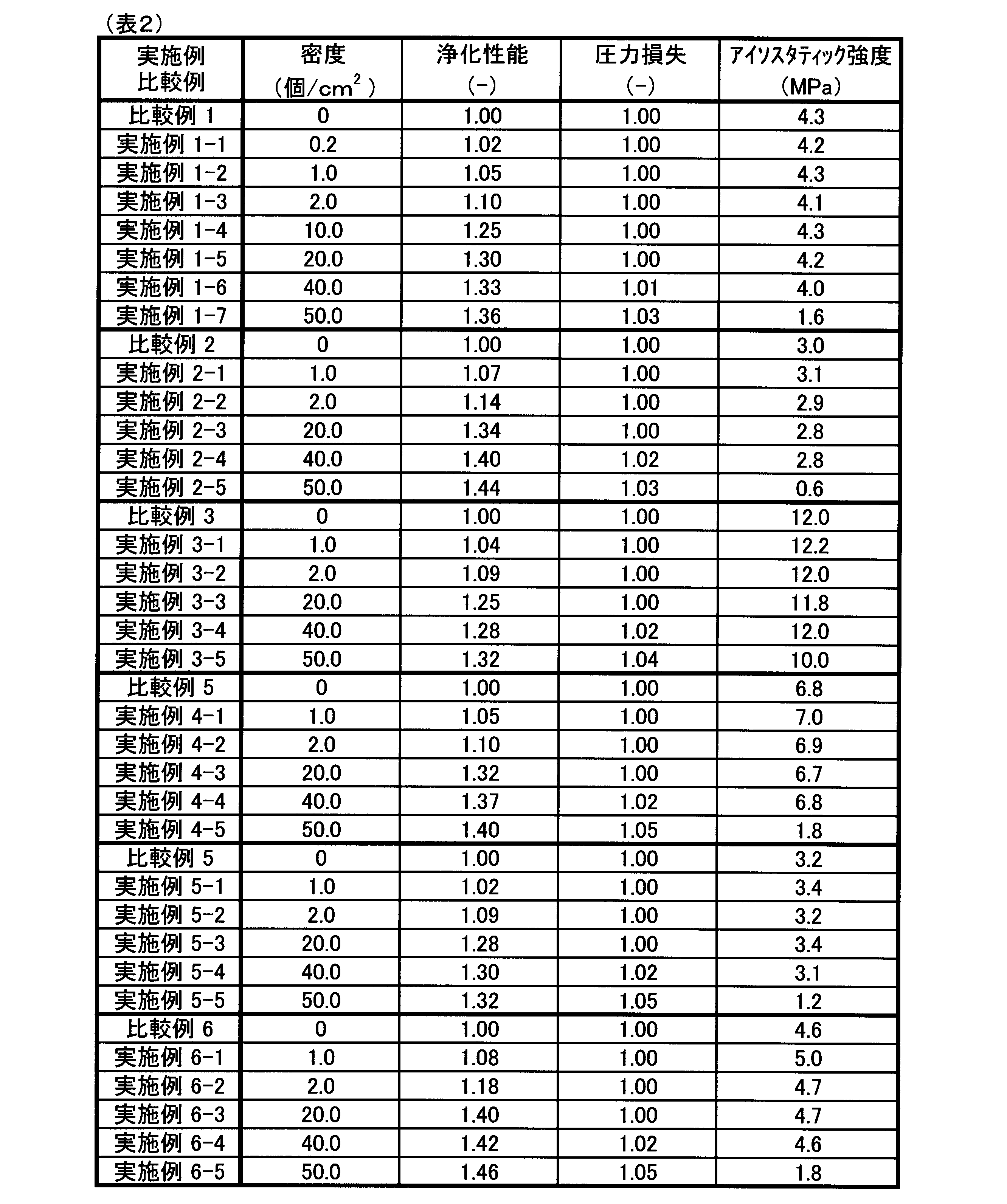
図11に実施例1-4の構造を一例として示すように、ハニカム構造体1のセル3は、六角形の断面形状とした。セルピッチPは1100μmであり、突起片4の長さL:0.45mm、高さH:200μm、距離D:4mmは、同じである。図示するように、隣り合う3つのセル3において、共通の頂点に続くセル壁2に、それぞれ突起片4が形成されていることが確認された。
実施例1-1~1-7のハニカム構造体1のそれぞれに、触媒層を形成して触媒体とした。また、突起片4を形成しないハニカム構造体1(すなわち、密度=0個/cm2)を比較例1として、同様に触媒層を形成し、触媒体とした。なお、これら触媒体は、触媒のコート量は同じであり、ハニカム構造体1の壁厚やセル密度による表面積の増減により、表1に示す触媒層の厚さtcが、40μm~70μmの範囲で変化している。
実施例1、比較例1において得られた触媒体について、モデルガスを用いた浄化性能試験を行い、浄化性能、圧力損失、アイソスタティック強度への影響を調べた。実施例1のハニカム構造体1は、セル3の壁厚を88μm(すなわち、3.5mil)、セル密度を600cps(すなわち、93個/cm2)とした。浄化性能、圧力損失は、比較例1の結果を1としたときの相対値で評価した。アイソスタティック強度は、JASO M 505-87に定める方法によりアイソスタティック強度試験を行い、ハニカム構造体1が破壊したときの圧力値(単位:MPa)で表した。
表2の結果から明らかなように、比較例1に対して、実施例1-1~1-7のように、突起片4が形成されることで、浄化性能が向上する。このとき、図12に示されるように、突起片4の密度(すなわち、図中の突起密度)が比較的小さくても性能向上効果が見られ、圧力損失とアイソスタティック強度(以下、適宜、強度と称する)の悪化は見られない。突起片4の密度が大きくなるに従い、圧力損失と強度を悪化させることなく、浄化性能が向上するが、密度がより大きくなると、圧力損失が大きくなり強度が低下する。
ハニカム構造体1を薄壁とした実施例2-1~2-5、比較例2においても(すなわち、壁厚50μm)、同様の傾向が見られた。ハニカム構造体1を厚壁とし、セル密度を小さくした実施例3-1~3-5、比較例3においても(すなわち、壁厚150μm、セル密度400cps;62個/cm2)、同様であった。これら結果から、突起片4の密度が1.0個/cm2以上であれば、例えば、5%以上の浄化性能の向上が得られ、2.0個/cm2以上であれば、10%以上の浄化性能の向上が得られる。好ましくは、40個/cm2以下とすることで、圧力損失の増加と強度低下を抑制することができる。
また、図13に示されるように、ハニカム構造体1のセル密度を増加させた実施例4-1~4-5、比較例4においても(すなわち、1200cps;186個/cm2)、同様の傾向が見られた。なお、浄化性能がより向上しているのは、セル密度が増えて、セル中心までの距離Dcが、セル密度が増える前に比べ短くなったためと推察される。また、圧力損失の増大も見られる。セル密度を減少させた実施例5-1~5-5、比較例5においても(すなわち、400cps;62個/cm2)、セル密度を増加させ、セル壁厚を減少させた実施例6-1~6-5、比較例6においても(すなわち、壁厚50μm、セル密度400cps;62個/cm2)、同様であった。
(実施例7~12)
実施例1~6と同様の方法で、表3に示すように、突起片4の高さHを25μm~700μmの範囲で変更したハニカム構造体1を製造した。ハニカム構造体1は、いずれも突起片4の密度を2.0個/cm2とした。実施例1~6と同様に、壁厚やセル密度を変更して、実施例7-1~7-8、実施例8-1~8-5、実施例9-1~9-5、実施例10-1~10-4、実施例11-1~11-4、実施例12-1~12-5のハニカム構造体1とし、これらハニカム構造体1のそれぞれに、触媒層を形成して触媒体とした。同様にして、浄化性能、圧力損失、アイソスタティック強度への影響を調べた結果を、表3に示す。また、突起片4を形成しない比較例1~6のハニカム構造体1(すなわち、高さH=0μm)の結果を、表3に併記した。
実施例1~6と同様の方法で、表3に示すように、突起片4の高さHを25μm~700μmの範囲で変更したハニカム構造体1を製造した。ハニカム構造体1は、いずれも突起片4の密度を2.0個/cm2とした。実施例1~6と同様に、壁厚やセル密度を変更して、実施例7-1~7-8、実施例8-1~8-5、実施例9-1~9-5、実施例10-1~10-4、実施例11-1~11-4、実施例12-1~12-5のハニカム構造体1とし、これらハニカム構造体1のそれぞれに、触媒層を形成して触媒体とした。同様にして、浄化性能、圧力損失、アイソスタティック強度への影響を調べた結果を、表3に示す。また、突起片4を形成しない比較例1~6のハニカム構造体1(すなわち、高さH=0μm)の結果を、表3に併記した。
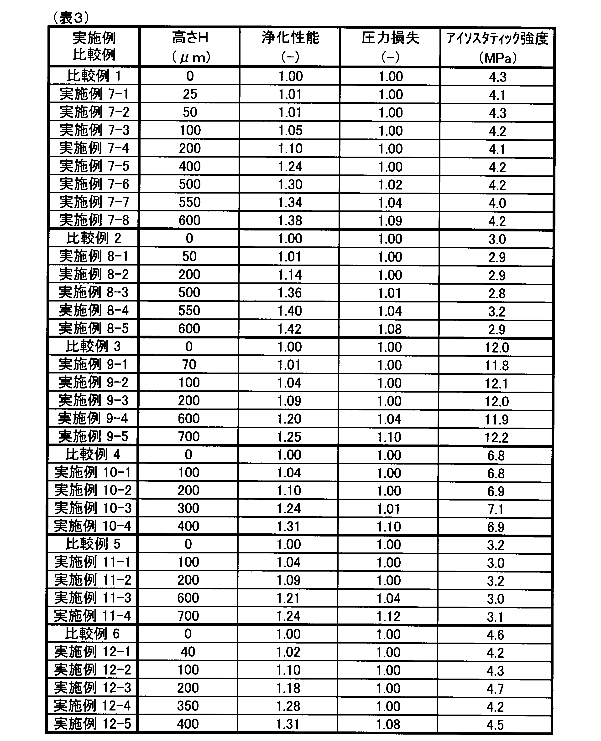
表3に明らかなように、比較例1に対して、実施例7-1~7-8のように、突起片4が形成されることで、浄化性能が向上する。このとき、図14に示されるように、突起片4の高さH(すなわち、図中の突起高さ)が高くなるほど、性能向上効果が見られ、触媒層の厚さtcを超えると、効果がより高くなる。また、高さHが500μmを超えると、圧力損失が徐々に悪化しており、この高さHは、セルピッチPとセル壁厚さtを用いて下記式のように算出される、セル中心までの距離Dcとほぼ同等である。高さHが、Dc≧H≧Dc/2の範囲であれば、圧力損失の増加や強度の低下は、ほとんどない。
Dc=(P-t)/2=(1.1mm-0.088mm)/2=0.51mm
Dc=(P-t)/2=(1.1mm-0.088mm)/2=0.51mm
ハニカム構造体1を薄壁とした実施例8-1~8-5(すなわち、壁厚50μm)においても、下記距離Dcに対して、同様の傾向が見られた。
Dc=(P-t)/2=(1.1mm-0.05mm)/2=0.53mm
ハニカム構造体1を厚壁とした実施例9-1~9-5(すなわち、壁厚150μm)においても、下記距離Dcに対して、同様の傾向が見られた。
Dc=(P-t)/2=(1.36mm-0.15mm)/2=0.61mm
さらに、セル密度を変更することにより、セルピッチPが増減している実施例10~12に対しても、下記距離Dcに対して、同様の傾向が見られた。
実施例10:Dc=(0.79mm-0.088mm)/2=0.35mm
実施例11:Dc=(1.36mm-0.088mm)/2=0.64mm
実施例12:Dc=(0.79mm-0.05mm)/2=0.37mm
図14、図15に示されるように、これら結果から、突起片4の高さHは、触媒層の厚さtc以上、好ましくは距離Dcの半分以上であり、距離Dc以下に設定されることが好ましい。
Dc=(P-t)/2=(1.1mm-0.05mm)/2=0.53mm
ハニカム構造体1を厚壁とした実施例9-1~9-5(すなわち、壁厚150μm)においても、下記距離Dcに対して、同様の傾向が見られた。
Dc=(P-t)/2=(1.36mm-0.15mm)/2=0.61mm
さらに、セル密度を変更することにより、セルピッチPが増減している実施例10~12に対しても、下記距離Dcに対して、同様の傾向が見られた。
実施例10:Dc=(0.79mm-0.088mm)/2=0.35mm
実施例11:Dc=(1.36mm-0.088mm)/2=0.64mm
実施例12:Dc=(0.79mm-0.05mm)/2=0.37mm
図14、図15に示されるように、これら結果から、突起片4の高さHは、触媒層の厚さtc以上、好ましくは距離Dcの半分以上であり、距離Dc以下に設定されることが好ましい。
(実施例13~18)
実施例1~6と同様の方法で、表4に示すように、突起片4間の距離Dを1μm~20μmの範囲で変更したハニカム構造体1を製造した。ハニカム構造体1は、いずれも突起片4の高さを200μmとし、突起片4の密度を1.0個/cm2~2.0個/cm2とした。実施例1~6と同様に、壁厚やセル密度を変更して、実施例13-1~13-5、実施例14-1~14-5、実施例15-1~15-5、実施例16-1~16-5、実施例17-1~17-5、実施例18-1~18-5のハニカム構造体1とし、これらハニカム構造体1のそれぞれに、触媒層を形成して触媒体とした。同様にして、浄化性能、圧力損失、強度への影響を調べた結果を、表4に示す。
実施例1~6と同様の方法で、表4に示すように、突起片4間の距離Dを1μm~20μmの範囲で変更したハニカム構造体1を製造した。ハニカム構造体1は、いずれも突起片4の高さを200μmとし、突起片4の密度を1.0個/cm2~2.0個/cm2とした。実施例1~6と同様に、壁厚やセル密度を変更して、実施例13-1~13-5、実施例14-1~14-5、実施例15-1~15-5、実施例16-1~16-5、実施例17-1~17-5、実施例18-1~18-5のハニカム構造体1とし、これらハニカム構造体1のそれぞれに、触媒層を形成して触媒体とした。同様にして、浄化性能、圧力損失、強度への影響を調べた結果を、表4に示す。
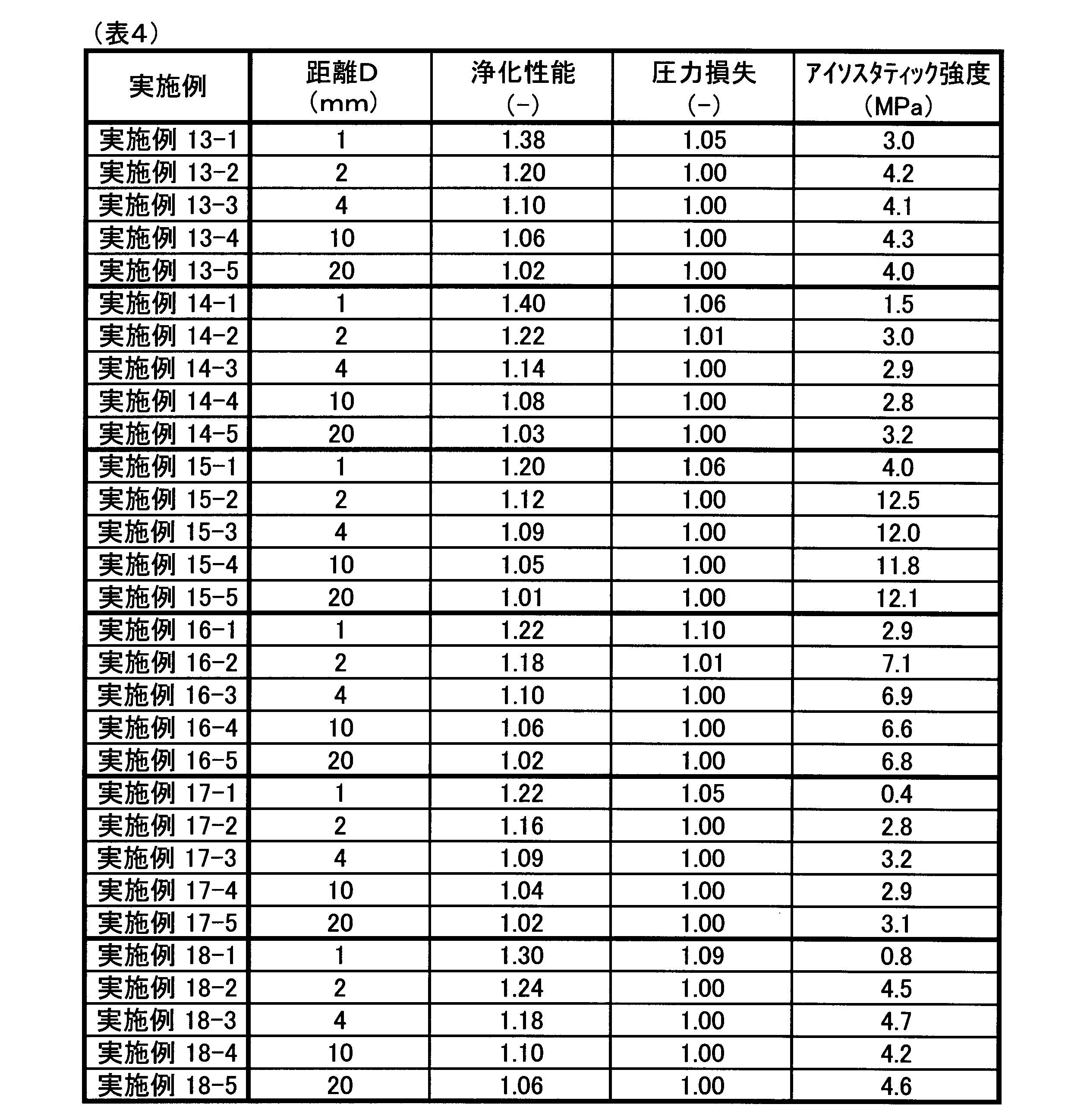
表4に明らかなように、実施例13-1~13-5では、突起片4間の距離Dに応じて、浄化性能が変化している。このとき、図16に示されるように、突起片4間の距離D(すなわち、図中の突起距離)が小さいほど、1つのセル3内に軸方向に配置される突起片4の数が増加することで、浄化性能が向上する。ただし、突起片4の長さL(すなわち、L=0.45mm)に対して、距離Dがごく小さい実施例13-1では(すなわち、D=1mm)、浄化性能は高いものの、圧力損失の増加と強度の低下が見られた。また、距離Dが20mmに近づくと、浄化性能の向上効果が小さくなる。
この傾向は、ハニカム構造体1を薄壁とした実施例14-1~14-5(すなわち、壁厚50μm)、厚壁とした実施例15-1~15-5(すなわち、壁厚150μm)においても、同様であった。さらに、図17に示されるように、セル密度を変更した、実施例16~18においても、同様であった。これら結果から、突起片4の距離Dは、長さLの2倍の長さ以上、好ましくは、2mm~20mmの範囲に設定されることが好ましい。
(実施例19~21)
実施例1と同様の方法で、表5に示すように、突起片4の高さHに対して、長さLを変更したハニカム構造体1を製造した。ハニカム構造体1は、いずれも壁厚88μm、セル密度600cpsであり、突起片4の密度を2.0個/cm2、突起片4の高さを200μm~400μmとした。実施例1と同様にして、突起片4の長さLを0.1mm~15.0mmの範囲で変更して、実施例19-1~19-7、実施例20-1~20-7、実施例21-1~21-7のハニカム構造体1とし、これらハニカム構造体1のそれぞれに、触媒層を形成して触媒体とした。同様にして、浄化性能、圧力損失、強度への影響を調べた結果を、表5に示す。
実施例1と同様の方法で、表5に示すように、突起片4の高さHに対して、長さLを変更したハニカム構造体1を製造した。ハニカム構造体1は、いずれも壁厚88μm、セル密度600cpsであり、突起片4の密度を2.0個/cm2、突起片4の高さを200μm~400μmとした。実施例1と同様にして、突起片4の長さLを0.1mm~15.0mmの範囲で変更して、実施例19-1~19-7、実施例20-1~20-7、実施例21-1~21-7のハニカム構造体1とし、これらハニカム構造体1のそれぞれに、触媒層を形成して触媒体とした。同様にして、浄化性能、圧力損失、強度への影響を調べた結果を、表5に示す。
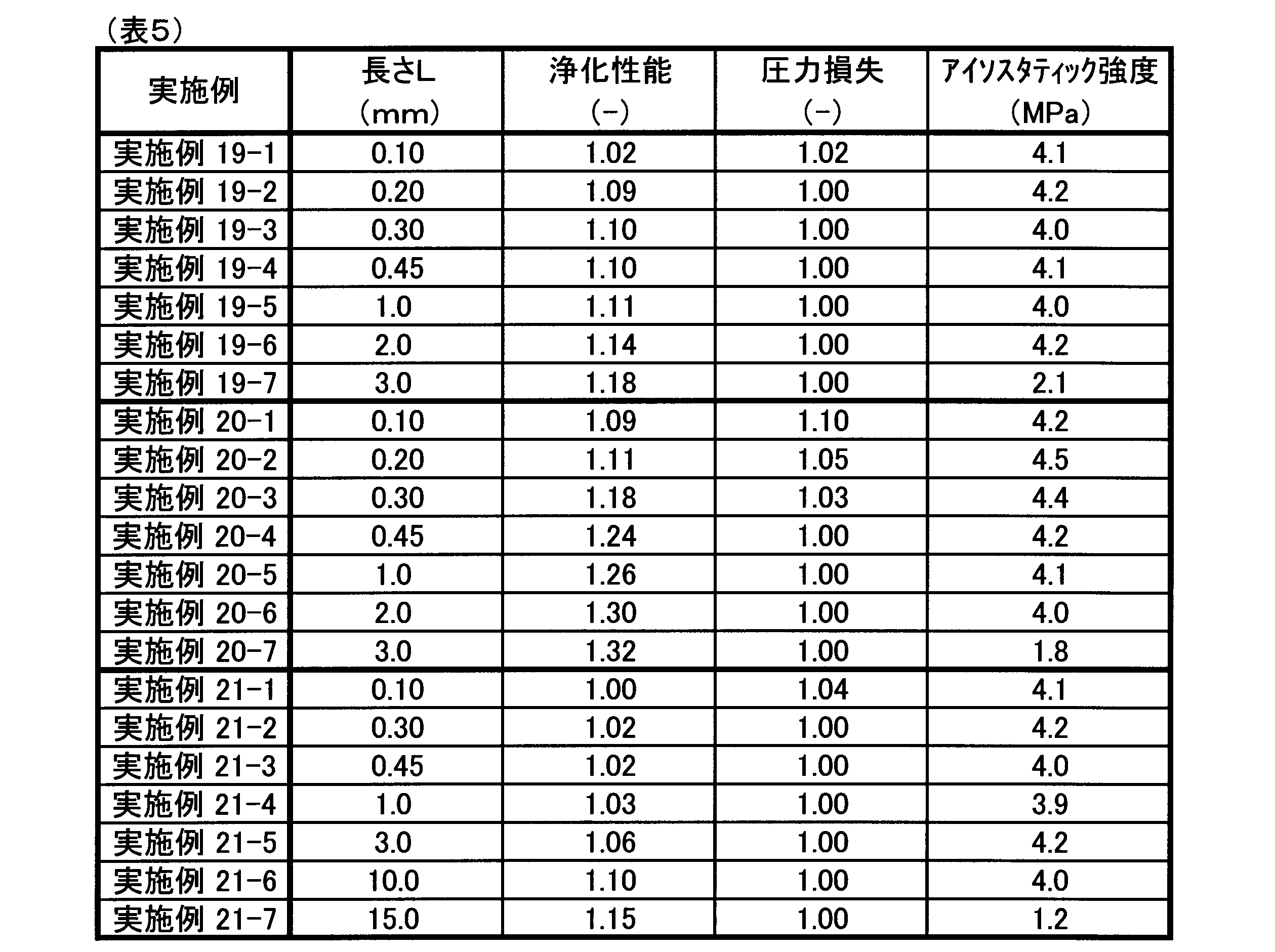
表5に明らかなように、実施例19-1~19-7では、突起片4の長さLが長くなるほど、浄化性能が向上する。このとき、図18に示されるように、突起片4の高さH(すなわち、H=200μm=0.2mm)に対して、実施例19-1のように長さLが小さいと(すなわち、L=0.1mm)、圧力損失が増加する。また、距離D(すなわち、D=4mm)に対して、実施例19-7のように長さLが長くなると(すなわち、L=3.0mm)、強度が低下する。
この傾向は、実施例20においても同様であり、突起片4の高さH(すなわち、H=400μm=0.4mm)に対して、実施例20-1のように長さLが小さいと(すなわち、L=0.3mm)、圧力損失が増加する。また、距離D(すなわち、D=4mm)に対して、実施例20-7のように長さLが長くなると(すなわち、L=3.0mm)、強度が低下する。実施例21においても、突起片4の高さH(すなわち、H=200μm=0.2mm)に対して、実施例22-1のように長さLが小さいと(すなわち、L=0.1mm)、圧力損失が増加する。また、距離D(すなわち、D=20mm)に対して、実施例21-7のように長さLが長くなると(すなわち、L=15.0mm)、強度が低下する。
これら結果から、突起片4の高さHより、長さLが長く、また、距離Dの1/2よりも、長さLが長くなるように(すなわち、L≧H、L≧D/2)、設定されることが好ましい。
本開示は、上記実施形態や上記実施例に記載した内容に限定されるものではなく、本発明の趣旨を超えない範囲で、種々の変更が可能である。例えば、ハニカム構造体1のセル形状は、四角形又は六角形以外の多角形、又は円形等、任意の形状とすることができる。複数のセル形状や、大きさの異なるセル形状を組み合わせてもよい。また、上記実施形態では、自動車用の排ガス浄化触媒への適用例として説明したが、自動車エンジンに限らず、各種装置からの排ガスを浄化する触媒体等、各種用途に任意に使用することができる。
Claims (9)
- 両端開口の筒状外皮(11)内を区画するセル壁(2)と、
該セル壁に囲まれ、上記筒状外皮の軸方向(X)に平行配設される多数のセル(3)と、を備える、ハニカム構造体(1)であって、
該多数のセルのうち少なくとも一部の上記セルには、上記セル壁を貫通する通孔(41)と、該通孔の端縁部から上記セルの内方に傾斜して突き出す突壁(42)と、を構成する突起片(4)が設けられる、ハニカム構造体。 - 上記突起片は、上記セル壁に設けられた切起し片からなる、請求項1に記載のハニカム構造体。
- 上記突起片を設けた上記セルが複数隣接して配置される、請求項1又は2に記載のハニカム構造体。
- 上記セルが開口する端面(12)に、上記突起片を投影した投影面において、上記突起片の単位面積当たりの密度が、1個/cm2以上である、請求項1~3のいずれか1項に記載のハニカム構造体。
- 上記突起片の先端の高さHと、上記軸方向の長さLとは、L≧Hの関係にある、請求項1~4のいずれか1項に記載のハニカム構造体。
- 上記突起片の先端の高さHと、上記セル壁と上記セルの中心との距離Dcとは、Dc≧Hの関係にある、請求項1~5のいずれか1項に記載のハニカム構造体。
- 上記突起片は、上記セル壁に、上記軸方向に間隔をおいて複数設けられる、請求項1~6のいずれか1項に記載のハニカム構造体。
- 複数の上記突起片の距離Dtと、上記軸方向の長さLとは、Dt/2≧Lの関係にある、請求項7に記載のハニカム構造体。
- ハニカム構造体(1)に触媒を担持してなる触媒体であって、
上記ハニカム構造体は、
両端開口の筒状外皮(11)内を区画するセル壁(2)と、
該セル壁に囲まれ、上記筒状外皮の軸方向(X)に平行配設される多数のセル(3)と、を備えており、
該多数のセルのうち少なくとも一部の上記セルには、上記セル壁を貫通する通孔(41)と、該通孔の端縁部から上記セルの内方に傾斜して突き出す突壁(42)と、を構成する突起片(4)が設けられる、触媒体。
Priority Applications (2)
| Application Number | Priority Date | Filing Date | Title |
|---|---|---|---|
| US16/071,498 US10883400B2 (en) | 2016-01-21 | 2016-01-18 | Honeycomb structure and catalyst body |
| CN201680079584.3A CN108472642B (zh) | 2016-01-21 | 2016-10-18 | 蜂窝结构体及催化剂体 |
Applications Claiming Priority (2)
| Application Number | Priority Date | Filing Date | Title |
|---|---|---|---|
| JP2016009838A JP6604214B2 (ja) | 2016-01-21 | 2016-01-21 | ハニカム構造体及び触媒体 |
| JP2016-009838 | 2016-01-21 |
Publications (1)
| Publication Number | Publication Date |
|---|---|
| WO2017126174A1 true WO2017126174A1 (ja) | 2017-07-27 |
Family
ID=59362714
Family Applications (1)
| Application Number | Title | Priority Date | Filing Date |
|---|---|---|---|
| PCT/JP2016/080846 Ceased WO2017126174A1 (ja) | 2016-01-21 | 2016-10-18 | ハニカム構造体及び触媒体 |
Country Status (4)
| Country | Link |
|---|---|
| US (1) | US10883400B2 (ja) |
| JP (1) | JP6604214B2 (ja) |
| CN (1) | CN108472642B (ja) |
| WO (1) | WO2017126174A1 (ja) |
Cited By (2)
| Publication number | Priority date | Publication date | Assignee | Title |
|---|---|---|---|---|
| WO2022137672A1 (ja) * | 2020-12-25 | 2022-06-30 | 日鉄ケミカル&マテリアル株式会社 | ハニカム型メタル担体、触媒コンバータ及びハニカム型メタル担体の製造方法 |
| JP7129535B1 (ja) | 2021-11-05 | 2022-09-01 | 日鉄ケミカル&マテリアル株式会社 | ハニカム型メタル担体及び触媒コンバータ |
Families Citing this family (2)
| Publication number | Priority date | Publication date | Assignee | Title |
|---|---|---|---|---|
| US11698015B2 (en) * | 2017-10-02 | 2023-07-11 | Corning Incorporated | Ceramic honeycomb bodies and method for canning thereof |
| US11890609B2 (en) * | 2019-09-12 | 2024-02-06 | Corning Incorporated | Honeycomb bodies with improved skin CTE and isostatic strength and methods of making the same |
Citations (3)
| Publication number | Priority date | Publication date | Assignee | Title |
|---|---|---|---|---|
| JP2002177793A (ja) * | 2000-10-02 | 2002-06-25 | Nippon Soken Inc | セラミック担体およびセラミック触媒体 |
| JP2005262098A (ja) * | 2004-03-18 | 2005-09-29 | Calsonic Kansei Corp | 金属製触媒担体 |
| JP2008115717A (ja) * | 2006-11-01 | 2008-05-22 | Toyota Motor Corp | 排ガス浄化装置 |
Family Cites Families (5)
| Publication number | Priority date | Publication date | Assignee | Title |
|---|---|---|---|---|
| JPH084749B2 (ja) * | 1985-01-21 | 1996-01-24 | 日本碍子株式会社 | セラミツクハニカム構造体 |
| WO2001028665A1 (en) | 1999-10-15 | 2001-04-26 | Abb Lummus Global, Inc. | Conversion of nitrogen oxides in the presence of a catalyst supported of a mesh-like structure |
| CN1852766A (zh) * | 2003-09-08 | 2006-10-25 | 恩格哈德公司 | 涂布基材及其制备方法 |
| JP4868714B2 (ja) * | 2004-04-12 | 2012-02-01 | トヨタ自動車株式会社 | 排ガス浄化フィルタ触媒 |
| JP4868713B2 (ja) * | 2004-04-12 | 2012-02-01 | トヨタ自動車株式会社 | 排ガス浄化フィルタ装置 |
-
2016
- 2016-01-18 US US16/071,498 patent/US10883400B2/en not_active Expired - Fee Related
- 2016-01-21 JP JP2016009838A patent/JP6604214B2/ja not_active Expired - Fee Related
- 2016-10-18 WO PCT/JP2016/080846 patent/WO2017126174A1/ja not_active Ceased
- 2016-10-18 CN CN201680079584.3A patent/CN108472642B/zh not_active Expired - Fee Related
Patent Citations (3)
| Publication number | Priority date | Publication date | Assignee | Title |
|---|---|---|---|---|
| JP2002177793A (ja) * | 2000-10-02 | 2002-06-25 | Nippon Soken Inc | セラミック担体およびセラミック触媒体 |
| JP2005262098A (ja) * | 2004-03-18 | 2005-09-29 | Calsonic Kansei Corp | 金属製触媒担体 |
| JP2008115717A (ja) * | 2006-11-01 | 2008-05-22 | Toyota Motor Corp | 排ガス浄化装置 |
Cited By (4)
| Publication number | Priority date | Publication date | Assignee | Title |
|---|---|---|---|---|
| WO2022137672A1 (ja) * | 2020-12-25 | 2022-06-30 | 日鉄ケミカル&マテリアル株式会社 | ハニカム型メタル担体、触媒コンバータ及びハニカム型メタル担体の製造方法 |
| JP2022101756A (ja) * | 2020-12-25 | 2022-07-07 | 日鉄ケミカル&マテリアル株式会社 | 触媒コンバータ及びハニカム型メタル担体の製造方法 |
| JP7129535B1 (ja) | 2021-11-05 | 2022-09-01 | 日鉄ケミカル&マテリアル株式会社 | ハニカム型メタル担体及び触媒コンバータ |
| JP2023069201A (ja) * | 2021-11-05 | 2023-05-18 | 日鉄ケミカル&マテリアル株式会社 | ハニカム型メタル担体及び触媒コンバータ |
Also Published As
| Publication number | Publication date |
|---|---|
| JP6604214B2 (ja) | 2019-11-13 |
| JP2017127825A (ja) | 2017-07-27 |
| CN108472642B (zh) | 2021-06-01 |
| US10883400B2 (en) | 2021-01-05 |
| US20190024551A1 (en) | 2019-01-24 |
| CN108472642A (zh) | 2018-08-31 |
Similar Documents
| Publication | Publication Date | Title |
|---|---|---|
| JP5405538B2 (ja) | ハニカム構造体 | |
| JP6339463B2 (ja) | ハニカム構造体 | |
| JP4159155B2 (ja) | セラミックハニカム構造体および押出金型 | |
| JP5144075B2 (ja) | ハニカム構造体及びその製造方法 | |
| JP6604214B2 (ja) | ハニカム構造体及び触媒体 | |
| EP2366970B1 (en) | Method of drying a honeycomb formed body | |
| US10632647B2 (en) | Honeycomb structure | |
| JP2014181143A (ja) | ハニカム構造体 | |
| US9555355B2 (en) | Manufacturing method for honeycomb structure and honeycomb structure | |
| JP6749853B2 (ja) | ハニカム構造体の製造方法及びハニカム構造体 | |
| JP2003238271A (ja) | 多孔質セラミック体の製造方法 | |
| EP3235565A1 (en) | Honeycomb structured body | |
| JP4071025B2 (ja) | ハニカム構造体の製造方法 | |
| JP6767914B2 (ja) | ハニカム構造体 | |
| JP2007083099A (ja) | 六角形ハニカム構造体及びその製造方法 | |
| JP6622741B2 (ja) | ハニカム構造体 | |
| JP6775458B2 (ja) | ハニカム構造体 | |
| JP7181704B2 (ja) | ハニカム構造体 | |
| JP2018027541A (ja) | ハニカム構造体、及びその製造方法 | |
| JP5945413B2 (ja) | 押出成形金型 | |
| JP5932416B2 (ja) | ハニカム構造体、及びハニカム触媒体 | |
| CN110314712B (zh) | 蜂窝结构体 | |
| JP2015144983A (ja) | ハニカム構造体、及びその製造方法 | |
| JP6767891B2 (ja) | ハニカム構造体の製造方法及びハニカム構造体 | |
| CN105983448B (zh) | 蜂窝结构体 |
Legal Events
| Date | Code | Title | Description |
|---|---|---|---|
| 121 | Ep: the epo has been informed by wipo that ep was designated in this application |
Ref document number: 16886414 Country of ref document: EP Kind code of ref document: A1 |
|
| NENP | Non-entry into the national phase |
Ref country code: DE |
|
| 122 | Ep: pct application non-entry in european phase |
Ref document number: 16886414 Country of ref document: EP Kind code of ref document: A1 |