WO2017122522A1 - 荷重発生装置 - Google Patents
荷重発生装置 Download PDFInfo
- Publication number
- WO2017122522A1 WO2017122522A1 PCT/JP2016/088684 JP2016088684W WO2017122522A1 WO 2017122522 A1 WO2017122522 A1 WO 2017122522A1 JP 2016088684 W JP2016088684 W JP 2016088684W WO 2017122522 A1 WO2017122522 A1 WO 2017122522A1
- Authority
- WO
- WIPO (PCT)
- Prior art keywords
- load
- elastic member
- generating device
- stroke amount
- generator
- Prior art date
- Legal status (The legal status is an assumption and is not a legal conclusion. Google has not performed a legal analysis and makes no representation as to the accuracy of the status listed.)
- Ceased
Links
Images








Classifications
-
- B—PERFORMING OPERATIONS; TRANSPORTING
- B60—VEHICLES IN GENERAL
- B60K—ARRANGEMENT OR MOUNTING OF PROPULSION UNITS OR OF TRANSMISSIONS IN VEHICLES; ARRANGEMENT OR MOUNTING OF PLURAL DIVERSE PRIME-MOVERS IN VEHICLES; AUXILIARY DRIVES FOR VEHICLES; INSTRUMENTATION OR DASHBOARDS FOR VEHICLES; ARRANGEMENTS IN CONNECTION WITH COOLING, AIR INTAKE, GAS EXHAUST OR FUEL SUPPLY OF PROPULSION UNITS IN VEHICLES
- B60K23/00—Arrangement or mounting of control devices for vehicle transmissions, or parts thereof, not otherwise provided for
- B60K23/02—Arrangement or mounting of control devices for vehicle transmissions, or parts thereof, not otherwise provided for for main transmission clutches
Definitions
- the present invention relates to a load generator that generates a load, and more particularly to a load generator having a high degree of freedom in design of load characteristics.
- the conventional load generator using a tension compression spring and a disc spring has a problem that the degree of freedom in designing the load characteristics is low because the tension compression spring and the disc spring are merely combined.
- the present invention has been made in view of the above problems, and an object of the present invention is to provide a load generator having a high degree of freedom in design of load characteristics.
- a load generating device of the present invention includes a piston member that is housed in a cylinder and reciprocates in a predetermined stroke direction, and a load generating member that generates a load to be applied to the piston member.
- a first elastic member having a positive gradient load characteristic and a second elastic member having at least a negative gradient load characteristic, wherein the first elastic member is connected to the second elastic member in a pre-compressed state. Yes.
- the load generated by the load generating member is applied to the piston member. Since the load generating member is composed of a first elastic member (an elastic member having a positive gradient load characteristic) and a second elastic member (an elastic member having at least a negative gradient load characteristic), the load characteristic of the load generating member is Is a combination of the load characteristics of the first elastic member and the second elastic member. In this case, since the first elastic member is connected to the second elastic member in a pre-compressed state, the load characteristic of the load generating member is obtained when the stroke amount of the piston member is gradually increased from zero.
- the load characteristic of the first elastic member is shown, and after exceeding the predetermined stroke amount, The load characteristics of the second elastic member are shown. Therefore, by adjusting the amount of pre-compression of the second elastic member, a load having a desired load characteristic can be generated, and the design flexibility of the load characteristic is high.
- the second elastic member may be constituted by a disc spring.
- the load characteristics of a disc spring gradually increase when the stroke amount of the piston member is gradually increased from zero, and gradually decrease when the predetermined peak value (maximum value) is exceeded. Increase gradually.
- the predetermined stroke amount the stroke amount at which the load of the first elastic member becomes equal to the precompression load of the second elastic member
- the stroke amount of the piston member is gradually increased from zero.
- the load characteristic of the load generating member reaches a predetermined stroke amount (a stroke amount at which the load of the first elastic member becomes equal to the precompression load of the second elastic member).
- the load gradually increases (becomes a positive gradient), and after exceeding the predetermined stroke amount, the load gradually decreases (becomes a negative gradient) as the stroke amount increases, and the stroke amount again. As it increases, it gradually increases (becomes a positive slope).
- load characteristics are similar to the load characteristics of the clutch pedal. In this way, by configuring the second elastic member with a disc spring, it is possible to generate a pseudo load having a load characteristic similar to that of the clutch pedal.
- the plurality of disc springs may be connected in series or in parallel in the second elastic member.
- the load characteristic of the second elastic member can be changed by selecting the number of disc springs or the series / parallel. Therefore, the load characteristic of the load generated by the load generating member can be changed.
- the first elastic member may be disposed inside the second elastic member.
- the first elastic member can be disposed inside the second elastic member, so that the degree of freedom in design is increased.
- the load generator of the present invention may include a support member that supports an end portion of the second elastic member.
- the end of the second elastic member is supported by the support member. Therefore, for example, even if the second elastic member is constituted by a plurality of disc springs, the plurality of disc springs can be appropriately connected.
- the first elastic member and the second elastic member may be arranged coaxially with a shaft member as a center.
- the coaxiality of the first elastic member and the second elastic member can be improved by the shaft member.
- the second elastic member may be constituted by a torsion spring.
- a plurality of torsion springs may be connected in parallel in the second elastic member.
- the load characteristic of the second elastic member can be changed by selecting the number of torsion springs. Therefore, the load characteristic of the load generated by the load generating member can be changed.
- the stroke amount of the second elastic member may be prevented from exceeding a predetermined limit stroke amount.
- This configuration allows the stopper to prevent the stroke amount of the second elastic member from exceeding the limit stroke and becoming an overstroke.
- the load generator of the present invention may include an air hole that communicates the air chamber in the cylinder with the outside.
- the piston member may include a second stopper for preventing the stroke amount of the first elastic member from exceeding a predetermined limit stroke amount.
- the second stopper can prevent the stroke amount of the first elastic member from exceeding the limit stroke and becoming an overstroke.
- the load generator of the present invention may be provided with a bleeder for discharging the air in the oil chamber in the cylinder to the outside.
- the first elastic member and the second elastic member may be connected via a hydraulic pipe.
- a clutch pedal connected to the first elastic member and the second elastic member via a hydraulic pipe may be provided, and a third elastic member may be provided in the clutch pedal.
- the load characteristic on the clutch pedal shows a load characteristic in which the load of the third elastic member is further added to the load characteristic added on the clutch pedal by the load generating device.
- the degree of freedom in designing the load characteristics on the pedal is increased.
- a load having desired load characteristics can be generated by adjusting the amount of pre-compression of the second elastic member.
- the automatic clutch system 1 includes an operation mode switching unit 2 that switches between a manual operation mode and an automatic operation mode.
- the manual operation mode is an operation mode in which the clutch 4 is connected / disconnected based on the pedal operation of the clutch pedal 3
- the automatic operation mode is an operation mode in which the actuator 6 is operated based on a control signal from the control unit 5. This is an operation mode for connecting and disconnecting.
- the clutch pedal 3 is provided with a stroke sensor 7 for detecting an operation amount (depression amount) of the pedal operation, and the control unit 5 receives a signal indicating the current depression amount of the clutch pedal 3 from the stroke sensor 7. .
- the control part 5 may receive the signal which shows the depression amount of the present accelerator pedal from the stroke sensor (not shown) of an accelerator pedal.
- the operation mode switching unit 2 is schematically shown.
- the manual operation mode as shown in FIG. 1
- the depression amount of the clutch pedal 3 is directly transmitted to the clutch 4, and the depression amount is determined. Accordingly, the clutch 4 is connected / disconnected.
- the automatic operation mode as shown in FIG. 2, a control signal is sent from the control unit 5 to the actuator 6, and the actuator 6 is operated according to the control signal to connect / disconnect the clutch 4.
- the operation mode switching unit 2 switches between the manual operation mode and the automatic operation mode based on the switching signal from the control unit 5.
- the operation mode switching unit 2 determines to switch from the automatic operation mode to the manual operation mode. In this case, until the depression amount of the clutch pedal 3 becomes zero, a control signal corresponding to the depression amount is transmitted from the control unit 5 to the actuator 6, and the clutch 4 is connected / disconnected according to the depression amount. . That is, the actuator 6 follows the pedal operation of the clutch pedal 3. When the depression amount of the clutch pedal 3 becomes zero, the operation mode switching unit 2 switches from the automatic operation mode to the manual operation mode.
- the operation mode switching unit 2 may switch from the automatic operation mode to the manual operation mode when the accelerator pedal is operated in the automatic operation mode.
- the automatic clutch system 1 includes a load generator 8 that generates a load (pseudo reaction force) corresponding to the operation amount of the pedal operation when the pedal operation of the clutch pedal 3 is performed in the automatic operation mode.
- the characteristic of the load is the reaction force characteristic (cover reaction force) of the pedal reaction force received from the clutch pedal 3 according to the operation amount of the pedal operation when the pedal operation is performed in the manual operation mode. Characteristic)) (see FIG. 5).
- FIG. 3 is an explanatory diagram showing a configuration of the load generating device 8 according to the first embodiment.
- the load generation device 8 includes a cylinder 10, a piston member 11 accommodated in the cylinder 10, and a load generation member 12 that generates a load applied to the piston member 11.
- the piston member 11 reciprocates in the cylinder 10 in a predetermined stroke direction (vertical direction in FIG. 3).
- the load generating member 12 includes a tension / compression spring member 13 (coil spring) and a disc spring member 14.
- the tension / compression spring member 13 and the disc spring member 14 are arranged in series.
- the disc spring member 14 of the present embodiment includes a single disc spring 15, and the disc spring 15 is pre-compressed.
- the disc spring member 15 is pre-compressed with 50-100% of the peak load of the disc spring 15 in the initial state. Compression is given.
- An end 16 on the inner diameter side of the disc spring 15 is supported by a support member 17, and an end 18 on the outer diameter side of the disc spring 15 is supported by a body 19.
- the tension compression spring member 13 is connected to the disc spring member 14 in a precompressed state.
- the upper end of the tension / compression spring member 13 is in contact with the piston member 11, and the lower end of the tension / compression spring member 13 is supported by a support member 17. It can be said that the support member 17 also serves as a sheet of the tension / compression spring member 13.
- the piston member 11 has a columnar main body 110, and an upper end portion of the tension compression spring member 13 is provided at the center of the lower surface (lower surface in FIG. 3) of the main body 110.
- a convex portion 111 is provided to be locked.
- the support member 17 has a disc-shaped main body 170, and a convex portion 171 to which the lower end portion of the tension / compression spring member 13 is locked is provided at the center of the upper surface of the main body 170. .
- a convex portion 172 to which the upper end portion of the disc spring member 14 is locked is provided at the center portion of the lower surface of the main body 170 of the support member 17.
- a lower end portion of the disc spring member 14 is locked to a stepped portion 190 provided on the body 19.
- the lower surface of the main body 170 of the support member 17 is a tapered surface.
- the disc spring 15 may be supported by the cylinder 10 on the inner end 16 of the disc spring 15 in a pre-compressed state.
- the cylinder 10 also serves as the support member 17.
- the load generating member 12 of the present embodiment is composed of the tension / compression spring member 13 and the disc spring member 14, the load generating member 12 has a load characteristic as shown in FIG.
- the load characteristics of the disc spring member 14 are combined.
- the tension compression spring member 13 has a positive gradient load characteristic
- the disc spring member 14 has at least a negative gradient load characteristic.
- the load characteristic of the load generation member 12 gradually increases the stroke amount of the piston member 11 from zero.
- the load generator 8 of the present embodiment it is possible to generate a load having a desired load characteristic by adjusting the amount of pre-compression of the disc spring member 14, and the design flexibility of the load characteristic. Is expensive.
- a large precompression to the disc spring 15 and arranging it in series with the tension compression spring an area in which only the tension compression spring is operated can be formed, so that the stroke amount of the disc spring 15 can be greatly reduced.
- the stress generated in the disc spring 15 can be reduced, the number of the disc springs 15 can be reduced, and the outer diameter (size) of the disc spring 15 can be reduced.
- the generator 8 can be realized.
- the load characteristic of the disc spring 15 gradually increases when the stroke amount of the piston member 11 is gradually increased from zero, and gradually decreases when a predetermined peak value (maximum value) is exceeded. Increase gradually. For example, when the predetermined stroke amount (the stroke amount at which the load of the tension compression spring member 13 becomes equal to the precompression load of the disc spring member 14) is set to a value near the peak value, the stroke amount of the piston member 11 is zero. Until the load characteristics of the load generating member 12 reaches a predetermined stroke amount (a stroke amount at which the load of the tension compression spring member 13 becomes equal to the precompression load of the disc spring member 14).
- the load gradually increases as the stroke amount increases (becomes a positive gradient), and after exceeding the predetermined stroke amount, the load gradually decreases as the stroke amount increases (becomes a negative gradient) Again, it gradually increases (becomes a positive gradient) as the stroke amount increases.
- load characteristics are similar to the load characteristics of the clutch pedal (see FIG. 5). Therefore, according to the load generator 8 of the present embodiment, it is possible to generate a pseudo load having a load characteristic similar to that of the clutch pedal.
- FIG. 6 is an explanatory diagram showing the configuration of the load generating device 8 of the present embodiment.
- a plurality of disc springs 15 are connected in series.
- the lower end portion of the disc spring member 14 is locked to a step portion 191 provided at the center portion of the body 19.
- a plurality of disc springs 15 may be connected in parallel.
- the lower end portion of the disc spring member 14 is locked to the step portion 190 provided at the end portion of the body 19.
- the load characteristics of the disc spring member 14 can be changed by selecting the number of disc springs 15 or the series / parallel. Therefore, the load characteristic of the load generated by the load generating member 12 can be changed. Further, by using a plurality of disc springs 15, the outer diameter (size) of the load generating member 12 can be reduced.
- FIG. 8 is an explanatory diagram showing the configuration of the load generating device 8 of the present embodiment.
- a movable cylinder 10 is employed, and a tension / compression spring member 13 is disposed inside a disc spring member 14.
- a piston member 11 and a sliding pin 20 are accommodated in the movable cylinder 10.
- the piston member 11 has a columnar main body 110, and the upper end portion of the tension / compression spring member 13 is engaged with the central portion of the lower surface (lower surface in FIG. 8) of the main body 110.
- the convex part 111 to be stopped is provided.
- a lower bent portion 100 in which the lower end portion of the tension / compression spring member 13 is locked is formed at the lower portion of the movable cylinder 10.
- a second convex portion 112 is provided at the center of the lower surface of the convex portion 111 of the piston member 11.
- the 2nd convex part 112 is comprised so that it can pass through the opening part 101 of the lower part of the movable cylinder 10, when the tension compression spring member 13 is compressed.
- an upper bent portion 102 in which the upper end portion of the disc spring member 14 is locked is formed at the upper portion of the movable cylinder 10.
- the lower end of the disc spring member 14 is locked on the bottom surface of the disc spring storage chamber 192 provided in the body 19.
- the tension / compression spring member 13 can be disposed inside the disc spring member 14, the degree of design freedom is increased. Further, in this case, since “the axial length of the portion that accommodates the disc spring 15” can be overlapped with “the axial length of the movable cylinder 10 + the stroke amount of the movable cylinder 10” in the axial direction, a load is generated. The size of the device 8 can be reduced. Further, since the interference between the disc spring 15 and the tension / compression spring member 13 can be prevented, it is possible to prevent a stroke failure due to an increase in the number of hiss or a catch.
- FIG. 9 is an explanatory diagram showing the configuration of the load generating device 8 of the present embodiment.
- a plurality of disc springs 15 are connected in series, and the end 16 on the inner diameter side of the disc spring 15 is connected to the first support member 21 (inner support).
- the end 18 on the outer diameter side of the disc spring 15 is supported by the second support member 22 (outer support member).
- the first support member 21 has a disk-shaped main body 210, and a lower end portion of the disc spring 15 disposed on the upper side of the first support member 21 is at the center of the upper surface of the main body 210.
- a convex portion 211 to be locked is provided.
- a convex portion 212 is provided at the center of the lower surface of the main body 210 of the first support member 21 so that the upper end portion of the disc spring 15 disposed below the first support member 21 is locked. ing. As shown in FIGS. 10 and 11, a plurality of disc springs 15 may be connected in parallel.
- the inner end 16 of the disc spring 15 is supported by the first support member 21, and the outer end 18 of the disc spring 15 is supported by the second support member 22.
- a plurality of disc springs 15 can be appropriately connected. Further, when a plurality of disc springs 15 are arranged in series, the stroke amount of the disc springs 15 becomes large (the disc springs 15 can be stroked larger than the horizontal state), and the degree of freedom in designing the load characteristics depends. improves. On the other hand, when a plurality of disc springs 15 are arranged in parallel, the disc springs 15 can be prevented from contacting each other (surface contact), and sliding hiss and twisting force can be reduced. In addition, compared with the structure of FIG. 10, the structure of FIG. 11 can reduce a twisting force more.
- FIG. 12 is an explanatory diagram showing a configuration of the load generating device 8 of the present embodiment.
- the tension / compression spring member 13 and the disc spring member 14 are arranged coaxially with the shaft member 23 as the center.
- the shaft member 23 is disposed so as to penetrate the support member 21 (inner support member).
- the shaft member 23 may be configured integrally with the piston member 11.
- it can be arranged coaxially with the shaft member 23 as the center.
- the coaxiality of the tension / compression spring member 13 and the disc spring member 14 can be improved by the shaft member 23.
- uneven wear due to shaft misalignment can be reduced, so that changes with time in the load characteristics of the load generator 8 can be suppressed.
- sliding hiss due to interference between the outer diameter of the disc spring 15 and the body 19 can be reduced.
- FIG. 15 is an explanatory diagram showing a configuration of the load generating device 8 of the present embodiment.
- the lower surface 24 of the support member 17 (inner support member) of the disc spring 15 serves as a stopper that prevents the disc spring 15 stroke amount from exceeding a predetermined limit stroke amount. It has the function of In other words, when the stroke amount of the disc spring 15 increases and exceeds the predetermined limit stroke amount, the lower surface 24 of the support member 17 (inner support member) comes into contact with the body 19, and the disc spring 15 It is possible to prevent the stroke amount from increasing.
- the lower surface 24 of the first support member 24 (inner support member) of the disc spring 15 may have a function as a stopper that prevents the disc spring 15 from exceeding a predetermined stroke amount.
- the disc spring 15 may be brought into direct contact with the body 19 so that the disc spring 15 has a function as a stopper.
- the stopper can prevent the stroke amount of the disc spring 15 from exceeding the limit stroke and becoming an overstroke. Therefore, the stress generated in the disc spring 15 during the overstroke can be reduced. As a result, the stress generated in the disc spring 15 can be reduced.
- the diameter (size) can be reduced, and a compact and highly loadable load generator 8 can be realized. Since the tension compression spring is compressed after the disc spring 15 stops, the clutch pedal stroke can be secured.
- FIG. 18 is an explanatory diagram showing the configuration of the load generating device 8 of the present embodiment.
- an air hole 25 communicating with the air chamber in the cylinder 10 is formed.
- the air hole 25 is formed in the shaft member 23.
- the air hole 25 may be formed in the body 19 as shown in FIG. 19, or may be formed in the cylinder 10 as shown in FIG.
- the air (air pressure) in the air chamber in the cylinder 10 can be released to the outside from the air hole 25, and the contraction caused by the temperature change of the air. You can cancel minutes. Therefore, even when the piston member 11 moves or when the temperature of the air changes, the internal pressure of the cylinder 10 does not change, so that no load (unintended load) resulting from the change of the internal pressure of the cylinder 10 occurs.
- FIG. 21 is an explanatory diagram showing a configuration of the load generator 8 of the present embodiment.
- the lower surface 26 of the piston member 11 has a function as a stopper (second stopper) that prevents the stroke amount of the tension / compression spring member 13 from exceeding a predetermined limit stroke amount. . That is, when the stroke amount of the tension / compression spring member 13 increases and exceeds the predetermined limit stroke amount, the lower surface 26 of the piston member 11 contacts the upper surface of the support member 21 (inner support member) of the disc spring 15. It is possible to prevent the stroke amount of the tension / compression spring member 13 from increasing further.
- the second stopper can prevent the stroke amount of the tension / compression spring member 13 from exceeding the limit stroke and becoming an overstroke. Thereby, the damage by adhesion
- FIG. 22 is an explanatory diagram showing the configuration of the load generating device 8 of the present embodiment. As shown in FIG. 22, in the present embodiment, a bleeder 27 that discharges the air in the oil chamber in the cylinder 10 to the outside is provided.
- the air in the cylinder 10 can be released from the bleeder 27.
- the air can be discharged from the bleeder 27 to the outside, so that load characteristic change (unintended load characteristic change) due to air mixing can be prevented.
- load characteristic change unintended load characteristic change
- it is possible to improve mountability and assemblability.
- FIG. 23 is an explanatory diagram showing a configuration of the load generating device 8 of the present embodiment.
- the tension / compression spring member 13 and the disc spring member 14 arranged at different places are connected via a hydraulic pipe 28.
- the tension / compression spring member 13 and the disc spring member 14 are connected in series via the hydraulic pipe 28.
- the tension / compression spring member 13 and the disc spring member 14 can be arranged at different locations via the hydraulic pipe 28, the degree of freedom in design is increased. In this case, even when a plurality of biston cylinders 10 are employed, a load characteristic equivalent to that of a single piston cylinder 10 can be realized. Mountability can be improved by separating the portion for accommodating the tension compression spring member 13 and the portion for accommodating the disc spring member 14.
- FIG. 24 is an explanatory diagram showing the configuration of the load generating device 8 of the present embodiment. As shown in FIG. 24, in the present embodiment, the clutch pedal 3 is provided with a third elastic member 32.
- the load characteristic on the clutch pedal 3 is a load characteristic in which the load of the third elastic member 32 is further added to the load characteristic added on the clutch pedal 3 by the load generator 8. As a result, the degree of freedom in designing the load characteristics on the clutch pedal 3 is increased.
- the second elastic member is constituted by the disc spring member 14
- the scope of the present invention is not limited to this.
- the second elastic member only needs to have at least negative load characteristics.
- the second elastic member can be constituted by a coil spring 29.
- the coil spring 29 is configured to have at least negative load characteristics. That is, when the piston member 11 is stroked in the pushing direction (downward direction in FIG. 25), the coil spring 29 is gradually compressed, and the load of the coil spring 29 is gradually increased. Thereafter, when the stroke position of the piston member 11 (position where the coil spring 29 can be compressed most) is exceeded, the coil spring 29 gradually expands as the piston member 11 is pushed in, and the load of the coil spring 29 gradually decreases.
- the load characteristic of the load generating member 12 is such that the stroke amount of the piston member 11 is zero.
- the load characteristics of the tension / compression spring member 13 are shown up to a predetermined stroke amount (a stroke amount at which the load of the tension / compression spring member 13 becomes equal to the precompression load of the coil spring 29). After the predetermined stroke amount is exceeded, the load characteristics after the precompression load of the coil spring 29 are connected in series.
- the second elastic member can be constituted by a torsion spring 30.
- the torsion spring 30 is configured to have at least negative load characteristics. That is, when the piston member 11 is stroked in the pushing direction (downward in FIG. 26), the torsion spring 30 is gradually compressed, and the load of the torsion spring 30 gradually increases. Thereafter, when the stroke position of the piston member 11 (position where the torsion spring 30 is reversed) is exceeded, the torsion spring 30 gradually expands as the piston member 11 is pushed in, and the load of the torsion spring 30 gradually decreases.
- the load characteristic of the load generating member 12 makes the stroke amount of the piston member 11 zero.
- the load characteristic of the tension compression spring member 13 is shown up to a predetermined stroke amount (a stroke amount at which the load of the tension compression spring member 13 becomes equal to the precompression load of the torsion spring 30). After the predetermined stroke amount is exceeded, the load characteristic after the precompression load of the torsion spring 30 is displayed in a load characteristic connected in series.
- the second elastic member can be composed of a rubber member 31.
- the rubber member 31 is configured to have at least negative load characteristics. That is, when the piston member 11 is stroked in the pushing direction (downward direction in FIG. 27), the rubber member 31 is gradually compressed, and the load on the rubber member 31 is gradually increased. Thereafter, when the stroke position of the piston member 11 (position where the stretched rubber member 31 yields) is exceeded, the rubber member 31 gradually expands as the piston member 11 is pushed in, and the load on the rubber member 31 gradually decreases.
- the load characteristic of the load generating member 12 is such that the stroke amount of the piston member 11 is zero.
- the load characteristic of the tension compression spring member 13 is shown up to a predetermined stroke amount (a stroke amount at which the load of the tension compression spring member 13 becomes equal to the precompression load of the rubber member 31). After the predetermined stroke amount is exceeded, the load characteristic after the precompression load of the rubber member 31 is displayed in series.
- the load generating device has an effect that the degree of freedom in design of load characteristics is high, and is useful for being applied to an automatic clutch system for a vehicle.
Landscapes
- Engineering & Computer Science (AREA)
- Chemical & Material Sciences (AREA)
- Combustion & Propulsion (AREA)
- Transportation (AREA)
- Mechanical Engineering (AREA)
- Springs (AREA)
- Arrangement And Mounting Of Devices That Control Transmission Of Motive Force (AREA)
Abstract
荷重発生装置は、シリンダに収容され、所定のストローク方向に往復移動を行うピストン部材と、ピストン部材に加える荷重を発生させる荷重発生部材を備える。荷重発生部材は、引張圧縮バネ部材と皿バネ部材を備え、引張圧縮バネ部材、予圧縮された状態の皿バネ部に接続されている。
Description
本発明は、荷重を発生させる荷重発生装置に関し、特に荷重特性の設計自由度の高い荷重発生装置に関する。
従来、車両用の自動クラッチシステムなどに荷重発生装置が適用されている。そのような荷重発生装置として、引張圧縮バネ(コイルスプリング)と板バネとカムを用いることによって、クラッチペダルと同様の負勾配特性を有する荷重特性を作りだすものが提案されている(例えば、特許文献1の図3参照)。しかし、引張圧縮バネと板バネとカムを用いた荷重発生装置では、実際のクラッチペダルと同様の荷重特性を実現するために、カムや板バネのサイズを大きくする必要があり、搭載性が低いという問題があった。
そこで従来、荷重発生装置として、引張圧縮バネと皿バネを用いることによって、クラッチペダルと同様の負勾配特性を有する荷重特性を作り出すものも提案されている(例えば、特許文献1の図1参照)。
しかしながら、従来の引張圧縮バネと皿バネを用いた荷重発生装置では、引張圧縮バネと皿バネを単に組み合わせているに過ぎないため、荷重特性の設計自由度が低いという問題があった。
本発明は、上記の課題に鑑みてなされたもので、荷重特性の設計自由度が高い荷重発生装置を提供することを目的とする。
本発明の荷重発生装置は、シリンダ内に収容され、所定のストローク方向に往復移動を行うピストン部材と、前記ピストン部材に加える荷重を発生させる荷重発生部材と、を備え、前記荷重発生部材は、正勾配の荷重特性を有する第1弾性部材と負勾配の荷重特性を少なくとも有する第2弾性部材とを備え、前記第1弾性部材は、予圧縮された状態の前記第2弾性部材に接続されている。
この構成により、荷重発生部材で発生させた荷重がピストン部材に加えられる。荷重発生部材が、第1弾性部材(正勾配の荷重特性を有する弾性部材)と第2弾性部材(負勾配の荷重特性を少なくとも有する弾性部材)で構成されているので、荷重発生部材の荷重特性は、第1弾性部材と第2弾性部材の荷重特性を組み合わせたものになる。この場合、第1弾性部材が予圧縮された状態の第2弾性部材に接続されているので、荷重発生部材の荷重特性は、ピストン部材のストローク量をゼロから徐々に増加させていったときに、所定のストローク量(第1弾性部材の荷重が第2弾性部材の予圧縮荷重と等しくなるストローク量)までは、第1弾性部材の荷重特性を示し、その所定のストローク量を超えた後は、第2弾性部材の荷重特性を示すようになる。したがって、第2弾性部材の予圧縮の量を調整することにより、所望の荷重特性を有する荷重を発生させることができ、荷重特性の設計自由度が高い。
また、本発明の荷重発生装置では、前記第2弾性部材は、皿バネで構成されてもよい。
皿バネの荷重特性は、一般に、ピストン部材のストローク量をゼロから徐々に増加させていくと、荷重が徐々に増加し、所定のピーク値(極大値)を超えると徐々に減少し、再度、徐々に増加する。例えば、上記の所定のストローク量(第1弾性部材の荷重が第2弾性部材の予圧縮荷重と等しくなるストローク量)をピーク値の近傍の値に設定すると、ピストン部材のストローク量をゼロから徐々に増加させていったときに、荷重発生部材の荷重特性は、所定のストローク量(第1弾性部材の荷重が第2弾性部材の予圧縮荷重と等しくなるストローク量)になるまでは、ストローク量の増加に応じて荷重が徐々に増加し(正勾配となり)、所定のストローク量を超えた後は、ストローク量の増加に応じて荷重が徐々に減少し(負勾配となり)、再度、ストローク量の増加に応じて徐々に増加する(正勾配となる)ようになる。このような荷重特性は、クラッチペダルの荷重特性に類似している。このようにして、第2弾性部材を皿バネで構成することにより、クラッチペダルに類似した荷重特性を有する疑似的な荷重を発生させることができる。
また、本発明の荷重発生装置では、前記第2弾性部材において、複数の前記皿バネが直列または並列に接続されてもよい。
この構成により、皿バネの枚数や直列/並列を選択することにより、第2弾性部材の荷重特性を変えることができる。したがって、荷重発生部材で発生させる荷重の荷重特性を変えることができる。
また、本発明の荷重発生装置では、前記第1弾性部材は、前記第2弾性部材の内側に配置されてもよい。
この構成により、第1弾性部材を第2弾性部材の内側に配置することができるので、設計の自由度が高くなる。
また、本発明の荷重発生装置は、前記第2弾性部材の端部を支持する支持部材を備えてもよい。
この構成により、第2弾性部材の端部が支持部材で支持される。したがって、例えば、第2弾性部材が複数の皿バネで構成される場合であっても、複数の皿バネを適切に接続することができる。
また、本発明の荷重発生装置では、前記第1弾性部材と前記第2弾性部材は、軸部材を中心にして同軸に配置されてもよい。
この構成により、第1弾性部材と第2弾性部材の同軸度を、軸部材によって向上させることができる。
また、本発明の荷重発生装置では、前記第2弾性部材は、捩りばねで構成されてもよい。
捩りばねを用いることによっても、例えば、ピストン部材のストローク量をゼロから徐々に増加させていくと、荷重が徐々に増加し、所定のピーク値(極大値)を超えると徐々に減少し、再度、徐々に増加する荷重特性を実現することができる。この場合にも、第1弾性部材が予圧縮された状態の第2弾性部材に接続されているので、荷重発生部材の荷重特性は、ピストン部材のストローク量をゼロから徐々に増加させていったときに、所定の
ストローク量(第1弾性部材の荷重が第2弾性部材の予圧縮荷重と等しくなるストローク量)までは、第1弾性部材の荷重特性を示し、その所定のストローク量を超えた後は、第2弾性部材の荷重特性を示すようになる。したがって、第2弾性部材の予圧縮の量を調整することにより、所望の荷重特性を有する荷重を発生させることができ、荷重特性の設計自由度が高い。
ストローク量(第1弾性部材の荷重が第2弾性部材の予圧縮荷重と等しくなるストローク量)までは、第1弾性部材の荷重特性を示し、その所定のストローク量を超えた後は、第2弾性部材の荷重特性を示すようになる。したがって、第2弾性部材の予圧縮の量を調整することにより、所望の荷重特性を有する荷重を発生させることができ、荷重特性の設計自由度が高い。
また、本発明の荷重発生装置では、前記第2弾性部材において、複数の前記捩りばねが並列に接続されてもよい。
この構成により、捩りばねの個数を選択することにより、第2弾性部材の荷重特性を変えることができる。したがって、荷重発生部材で発生させる荷重の荷重特性を変えることができる。
また、本発明の荷重発生装置では、前記第2弾性部材のストローク量が所定の限度ストローク量を超えるのを防止してもよい。
この構成により、第2弾性部材のストローク量が限度ストロークを超えてオーバーストロークになるのを、ストッパによって防止することができる。
また、本発明の荷重発生装置は、前記シリンダ内の空気室と外部とを連通する空気穴を備えてもよい。
この構成により、ピストン部材をストローク方向に移動させるときに、シリンダ内の空気室の空気(空気圧)を空気穴から外部に逃がすことができ、また、空気の温度変化に伴う収縮分をキャンセルすることができる。したがって、ピストンの移動時や、空気の温度変化時においても、シリンダ内圧が変化することがないから、シリンダ内圧変化に起因する荷重(意図しない荷重)が発生しない。
また、本発明の荷重発生装置では、前記ピストン部材は、前記第1弾性部材のストローク量が所定の限度ストローク量を超えるのを防止する第2のストッパを備えてもよい。
この構成により、第1弾性部材のストローク量が限度ストロークを超えてオーバーストロークになるのを、第2のストッパによって防止することができる。
また、本発明の荷重発生装置では、前記シリンダ内の油室内の空気を外部に排出するブリーダを備えてもよい。
この構成により、組み付け時等のシリンダ室内に空気が入った場合に、ブリーダから空気を外部に排出できるので、空気混入による荷重特性変化(意図しない荷重特性変化)を防止することができる。また、配管上にブリーダを設ける必要がないため、搭載性や組付け性を向上させることができる。
また、本発明の荷重発生装置では、前記第1弾性部材と前記第2弾性部材とが油圧配管を介して接続されてもよい。
この構成により、油圧配管を介することによって第1弾性部材と第2弾性部材を異なる場所に配置することができるので、設計の自由度が高くなる。
また、本発明の荷重発生装置では、前記第1弾性部材および前記第2弾性部材に油圧配管を介して接続されるクラッチペダルを備え、前記クラッチペダルに、第3弾性部材を備えてもよい。
この構成により、クラッチペダル上の荷重特性は、荷重発生装置によってクラッチペダル上に付加される荷重特性に対して、第3弾性部材の荷重がさらに付加された荷重特性を示すようになるので、クラッチペダル上の荷重特性の設計自由度が高くなる。
本発明によれば、第2弾性部材の予圧縮の量を調整することにより、所望の荷重特性を有する荷重を発生させることができる。
以下、本発明の実施の形態の荷重発生装置について、図面を用いて説明する。本実施の形態では、車両用の自動クラッチシステム等に用いられる荷重発生装置の場合を例示する。
(第1の実施の形態)
本発明の第1の実施の形態の荷重発生装置の構成を、図面を参照して説明する。図1および図2は、本実施の形態の荷重発生装置が適用される自動クラッチシステムの説明図である。図1および図2に示すように、自動クラッチシステム1は、手動操作モードと自動操作モードを切り替える操作モード切替部2を備えている。手動操作モードは、クラッチペダル3のペダル操作に基づいてクラッチ4の断接を行う操作モードであり、自動操作モードは、制御部5からの制御信号に基づいてアクチュエータ6が動作してクラッチ4の断接を行う操作モードである。
本発明の第1の実施の形態の荷重発生装置の構成を、図面を参照して説明する。図1および図2は、本実施の形態の荷重発生装置が適用される自動クラッチシステムの説明図である。図1および図2に示すように、自動クラッチシステム1は、手動操作モードと自動操作モードを切り替える操作モード切替部2を備えている。手動操作モードは、クラッチペダル3のペダル操作に基づいてクラッチ4の断接を行う操作モードであり、自動操作モードは、制御部5からの制御信号に基づいてアクチュエータ6が動作してクラッチ4の断接を行う操作モードである。
クラッチペダル3には、ペダル操作の操作量(踏み込み量)を検知するストロークセンサ7が設けられており、制御部5は、ストロークセンサ7から現在のクラッチペダル3の踏み込み量を示す信号を受信する。なお、制御部5は、アクセルペダルのストロークセンサ(図示せず)から現在のアクセルペダルの踏み込み量を示す信号を受信してもよい。
図1および図2では、操作モード切替部2が模式的に示されており、手動操作モードでは、図1に示すように、クラッチペダル3の踏み込み量がクラッチ4へ直接伝えられ、踏み込み量に応じてクラッチ4の断接が行われる。一方、自動操作モードでは、図2に示すように、制御部5からアクチュエータ6へ制御信号が送られ、制御信号に応じてアクチュエータ6が作動してクラッチ4の断接が行われる。
操作モード切替部2は、制御部5からの切替信号に基づいて手動操作モードと自動操作モードの切り替えを行う。
一方、操作モード切替部2は、自動操作モード時にクラッチペダル3のペダル操作が行われると、制御部5は自動操作モードから手動操作モードへ切り替え判定をする。この場合、クラッチペダル3の踏み込み量がゼロになるまでの間は、踏み込み量に応じた制御信号が制御部5からアクチュエータ6に送信されて、踏み込み量に応じたクラッチ4の断接が行われる。すなわち、アクチュエータ6がクラッチペダル3のペダル操作に追従する。そして、クラッチペダル3の踏み込み量がゼロになったときに、操作モード切替部2は、自動操作モードから手動操作モードへ切り替える。
また、操作モード切替部2は、自動操作モード時にアクセルペダルのペダル操作が行われた場合に、自動操作モードから手動操作モードへ切り替えてもよい。
そして、この自動クラッチシステム1には、自動操作モード時にクラッチペダル3のペダル操作が行われた場合に、そのペダル操作の操作量に応じた荷重(擬似反力)を発生させる荷重発生装置8が設けられている。その荷重の特性(擬似反力の特性)は、手動操作モード時にペダル操作が行われた場合に、ペダル操作の操作量に応じてクラッチペダル3から受けるペダル反力の反力特性(カバー反力特性)と類似するように設定されている(図5参照)。
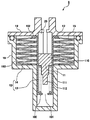
図3は、第1の実施の形態の荷重発生装置8の構成を示す説明図である。図3に示すように、荷重発生装置8は、シリンダ10と、シリンダ10内に収容されるピストン部材11と、ピストン部材11に加える荷重を発生させる荷重発生部材12を備えている。ピストン部材11は、シリンダ10内において、所定のストローク方向(図3における上下方向)に往復移動を行う。
荷重発生部材12は、引張圧縮バネ部材13(コイルスプリング)と皿バネ部材14とで構成されている。引張圧縮バネ部材13と皿バネ部材14は直列に配置されている。本実施の形態の皿バネ部材14は、1つの皿バネ15を備えており、皿バネ15は、予圧縮されており、例えば、初期状態で皿バネ15のピーク荷重の50~100%の予圧縮が与えられている。皿バネ15の内径側の端部16は、支持部材17によって支持されており、皿バネ15の外径側の端部18は、ボデー19により支持されている。引張圧縮バネ部材13は、予圧縮された状態の皿バネ部材14に接続されている。引張圧縮バネ部材13の上側の端部は、ピストン部材11に当接しており、引張圧縮バネ部材13の下側の端部は、支持部材17によって支持されている。支持部材17は、引張圧縮バネ部材13のシートを兼ねているともいえる。
図3に示すように、ピストン部材11は、円柱状の本体110を有しており、本体110の下面(図3における下側の面)の中央部には、引張圧縮バネ部材13の上端部が係止される凸部111が設けられている。また、支持部材17は、円板状の本体170を有しており、本体170の上面の中央部には、引張圧縮バネ部材13の下端部が係止される凸部171が設けられている。また、支持部材17の本体170の下面の中央部には、皿バネ部材14の上端部が係止される凸部172が設けられている。皿バネ部材14の下端部は、ボデー19に設けられた段部190に係止されている。なお、支持部材17の本体170の下面は、テーパ面とされている。
なお、図4に示すように、皿バネ15は、予圧縮された状態で内径側の端部16がシリンダ10によって支持されてもよい。この場合には、シリンダ10が支持部材17を兼ねているともいえる。
以上のように構成された荷重発生装置8の動作原理について、図5を参照して説明する。本実施の形態の荷重発生部材12は、引張圧縮バネ部材13と皿バネ部材14で構成されているので、荷重発生部材12の荷重特性は、図5に示すように、引張圧縮バネ部材13と皿バネ部材14の荷重特性を組み合わせたものになる。引張圧縮バネ部材13は、正勾配の荷重特性を有しており、皿バネ部材14は負勾配の荷重特性を少なくとも有している。この場合、引張圧縮バネ部材13が予圧縮された状態の皿バネ部材14に接続されているので、荷重発生部材12の荷重特性は、ピストン部材11のストローク量をゼロから徐々に増加させていったときに、所定のストローク量(引張圧縮バネ部材13の荷重が皿バネ部材14の予圧縮荷重と等しくなるストローク量)までは、引張圧縮バネ部材13の荷重特性を示し、その所定のストローク量を超えた後は、皿バネ部材14の予圧縮荷重以降の荷重が直列に接続された荷重特性を示すようになる。
したがって、本実施の形態の荷重発生装置8によれば、皿バネ部材14の予圧縮の量を調整することにより、所望の荷重特性を有する荷重を発生させることができ、荷重特性の設計自由度が高い。また、皿バネ15に大きな予圧縮を与えて引張圧縮バネと直列に配置することにより、引張圧縮バネのみが作動する領域ができるので、皿バネ15のストローク量を大幅に減少させることができる。その結果、皿バネ15に発生する応力を減らすことができるので、皿バネ15の枚数を減らすことや、皿バネ15の外径(サイズ)を縮小することができ、コンパクトで搭載性の高い荷重発生装置8を実現することができる。
一般に皿バネ15の荷重特性は、ピストン部材11のストローク量をゼロから徐々に増加させていくと、荷重が徐々に増加し、所定のピーク値(極大値)を超えると徐々に減少し、再度、徐々に増加する。例えば、上記の所定のストローク量(引張圧縮バネ部材13の荷重が皿バネ部材14の予圧縮荷重と等しくなるストローク量)をピーク値の近傍の値に設定すると、ピストン部材11のストローク量をゼロから徐々に増加させていったときに、荷重発生部材12の荷重特性は、所定のストローク量(引張圧縮バネ部材13の荷重が皿バネ部材14の予圧縮荷重と等しくなるストローク量)になるまでは、ストローク量の増加に応じて荷重が徐々に増加し(正勾配となり)、所定のストローク量を超えた後は、ストローク量の増加に応じて荷重が徐々に減少し(負勾配となり)、再度、ストローク量の増加に応じて徐々に増加する(正勾配となる)ようになる。このような荷重特性は、クラッチペダルの荷重特性に類似している(図5参照)。したがって、本実施の形態の荷重発生装置8によれば、クラッチペダルに類似した荷重特性を有する疑似的な荷重を発生させることができる。
(第2の実施の形態)
次に、本発明の第2の実施の形態の荷重発生装置8について説明する。ここでは、第2の実施の形態の荷重発生装置8が、第1の実施の形態と相違する点を中心に説明する。ここで特に言及しない限り、本実施の形態の構成および動作は、第1の実施の形態と同様である。
次に、本発明の第2の実施の形態の荷重発生装置8について説明する。ここでは、第2の実施の形態の荷重発生装置8が、第1の実施の形態と相違する点を中心に説明する。ここで特に言及しない限り、本実施の形態の構成および動作は、第1の実施の形態と同様である。
図6は、本実施の形態の荷重発生装置8の構成を示す説明図である。図6に示すように、本実施の形態の皿バネ部材14では、複数の皿バネ15が直列に接続されている。この場合、皿バネ部材14の下端部は、ボデー19の中央部に設けられた段部191に係止される。なお、図7に示すように、複数の皿バネ15が並列に接続されてもよい。この場合、皿バネ部材14の下端部は、ボデー19の端部に設けられた段部190に係止される。
このような第2の実施の形態の荷重発生装置8によっても、第1の実施の形態と同様の作用効果が奏される。
本実施の形態では、皿バネ15の枚数や直列/並列を選択することにより、皿バネ部材14の荷重特性を変えることができる。したがって、荷重発生部材12で発生させる荷重の荷重特性を変えることができる。また、複数の皿バネ15を用いることにより、荷重発生部材12の外径(サイズ)を縮小することができる。
(第3の実施の形態)
次に、本発明の第3の実施の形態の荷重発生装置8について説明する。ここでは、第3の実施の形態の荷重発生装置8が、第1の実施の形態と相違する点を中心に説明する。ここで特に言及しない限り、本実施の形態の構成および動作は、第1の実施の形態と同様である。
次に、本発明の第3の実施の形態の荷重発生装置8について説明する。ここでは、第3の実施の形態の荷重発生装置8が、第1の実施の形態と相違する点を中心に説明する。ここで特に言及しない限り、本実施の形態の構成および動作は、第1の実施の形態と同様である。
図8は、本実施の形態の荷重発生装置8の構成を示す説明図である。図8に示すように、本実施の形態では、可動式のシリンダ10が採用されており、引張圧縮バネ部材13が、皿バネ部材14の内側に配置されている。可動式のシリンダ10内には、ピストン部材11と摺動ピン20が収容されている。
図8に示すように、ピストン部材11は、円柱状の本体110を有し、本体110の下面(図8における下側の面)の中央部には、引張圧縮バネ部材13の上端部が係止される凸部111が設けられている。可動式のシリンダ10の下部には、引張圧縮バネ部材13の下端部が係止される下側屈曲部100が形成されている。さらに、ピストン部材11の凸部111の下面の中央部には、第2凸部112が設けられている。第2凸部112は、引張圧縮バネ部材13が圧縮されたときに、可動式のシリンダ10の下部の開口部101を通り抜けることができるように構成されている。また、可動式のシリンダ10の上部には、皿バネ部材14の上端部が係止される上側屈曲部102が形成されている。皿バネ部材14の下端部は、ボデー19に設けられた皿バネ収納室192の底面で係止される。
このような第3の実施の形態の荷重発生装置8によっても、第1の実施の形態と同様の作用効果が奏される。
本実施の形態では、引張圧縮バネ部材13を皿バネ部材14の内側に配置することができるので、設計の自由度が高くなる。また、この場合、「皿バネ15を収容する部分の軸長」を「可動式のシリンダ10の軸長+可動式のシリンダ10のストローク量」と軸方向に重複させることができるので、荷重発生装置8のサイズを小さくすることができる。さらに、皿バネ15と引張圧縮バネ部材13との干渉を防止できるので、ヒスの増加や引っかかりによるストローク不良を防止することができる。
(第4の実施の形態)
次に、本発明の第4の実施の形態の荷重発生装置8について説明する。ここでは、第4の実施の形態の荷重発生装置8が、第1の実施の形態と相違する点を中心に説明する。ここで特に言及しない限り、本実施の形態の構成および動作は、第1の実施の形態と同様である。
次に、本発明の第4の実施の形態の荷重発生装置8について説明する。ここでは、第4の実施の形態の荷重発生装置8が、第1の実施の形態と相違する点を中心に説明する。ここで特に言及しない限り、本実施の形態の構成および動作は、第1の実施の形態と同様である。
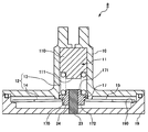
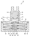
図9は、本実施の形態の荷重発生装置8の構成を示す説明図である。図9に示すように、本実施の形態の皿バネ部材14では、複数の皿バネ15が直列に接続され、皿バネ15の内径側の端部16が、第1の支持部材21(内側支持部材)によって支持されており、皿バネ15の外径側の端部18が、第2の支持部材22(外側支持部材)によって支持されている。第1の支持部材21は、円板状の本体210を有しており、本体210の上面の中央部には、その第1の支持部材21の上側に配置される皿バネ15の下端部が係止される凸部211が設けられている。また、第1の支持部材21の本体210の下面の中央部には、その第1の支持部材21の下側に配置される皿バネ15の上端部が係止される凸部212が設けられている。なお、図10および図11に示すように、複数の皿バネ15が並列に接続されてもよい。
このような第4の実施の形態の荷重発生装置8によっても、第1の実施の形態と同様の作用効果が奏される。
本実施の形態では、皿バネ15の内径側の端部16が第1の支持部材21で支持され、皿バネ15の外径側の端部18が第2の支持部材22で支持されるので、複数の皿バネ15を適切に接続することができる。また、複数の皿バネ15が直列に配置される場合には、皿バネ15のストローク量が大きくなり(水平状態より大きく皿バネ15がストロークできるようになり)、荷重特性の設計自由度うが向上する。一方、複数の皿バネ15が並列に配置される場合には、皿バネ15が相互に接触(面接触)するのを防止することができ、摺動ヒスやこじり力を低減することができる。なお、図10の構成に比べると、図11の構成のほうが、こじり力をより低減することができる。
(第5の実施の形態)
次に、本発明の第5の実施の形態の荷重発生装置8について説明する。ここでは、第5の実施の形態の荷重発生装置8が、第1の実施の形態と相違する点を中心に説明する。ここで特に言及しない限り、本実施の形態の構成および動作は、第1の実施の形態と同様である。
次に、本発明の第5の実施の形態の荷重発生装置8について説明する。ここでは、第5の実施の形態の荷重発生装置8が、第1の実施の形態と相違する点を中心に説明する。ここで特に言及しない限り、本実施の形態の構成および動作は、第1の実施の形態と同様である。
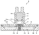
図12は、本実施の形態の荷重発生装置8の構成を示す説明図である。図12に示すように、本実施の形態では、引張圧縮バネ部材13と皿バネ部材14が、軸部材23を中心にして同軸に配置されている。この場合、支持部材21(内側支持部材)を貫通するように軸部材23が配置されている。なお、図13に示すように、軸部材23はピストン部材11と一体に構成されてもよい。また、図14に示すように、可動式のシリンダ10を採用した場合でも、軸部材23を中心にして同軸に配置することができる。
このような第5の実施の形態の荷重発生装置8によっても、第1の実施の形態と同様の作用効果が奏される。
本実施の形態では、引張圧縮バネ部材13と皿バネ部材14の同軸度を、軸部材23によって向上させることができる。これにより、軸ずれによる偏摩耗を低減することができるので、荷重発生装置8の荷重特性の経時的な変化を抑制することができる。また、皿バネ15の外径とボデー19の干渉による摺動ヒスを低減することができる。
(第6の実施の形態)
次に、本発明の第6の実施の形態の荷重発生装置8について説明する。ここでは、第6の実施の形態の荷重発生装置8が、第1の実施の形態と相違する点を中心に説明する。ここで特に言及しない限り、本実施の形態の構成および動作は、第1の実施の形態と同様である。
次に、本発明の第6の実施の形態の荷重発生装置8について説明する。ここでは、第6の実施の形態の荷重発生装置8が、第1の実施の形態と相違する点を中心に説明する。ここで特に言及しない限り、本実施の形態の構成および動作は、第1の実施の形態と同様である。
図15は、本実施の形態の荷重発生装置8の構成を示す説明図である。図15に示すように、本実施の形態では、皿バネ15の支持部材17(内側支持部材)の下面24が、皿バネ15のストローク量が所定の限度ストローク量を超えるのを防止するストッパとしての機能を有している。すなわち、皿バネ15のストローク量が増加していき、所定の限度ストローク量を超えようとすると、支持部材17(内側支持部材)の下面24がボデー19に当接し、それ以上、皿バネ15のストローク量が増加するのを防止することができる。
なお、図16に示すように、複数の皿バネ15を直列に配置した場合でも、同様の構成を採用することができる。すなわち、皿バネ15の第1の支持部材24(内側支持部材)の下面24が、皿バネ15のストローク量が所定の限度ストローク量を超えるのを防止するストッパとしての機能を有してもよい。また、図17に示すように、皿バネ15を直接ボデー19に当接させて、皿バネ15にストッパとしての機能をもたせてもよい。
このような第6の実施の形態の荷重発生装置8によっても、第1の実施の形態と同様の作用効果が奏される。
本実施の形態では、皿バネ15のストローク量が限度ストロークを超えてオーバーストロークになるのを、ストッパによって防止することができる。そのため、オーバーストローク時に皿バネ15に発生する応力を減らすことができ、その結果、皿バネ15に発生する応力を減らすことができるので、皿バネ15の枚数を減らすことや、皿バネ15の外径(サイズ)を縮小することができ、コンパクトで搭載性の高い荷重発生装置8を実現することができる。なお、皿バネ15のストロークが止まった後は、引張圧縮バネが圧縮されるので、クラッチペダルのストロークは確保することができる。
(第7の実施の形態)
次に、本発明の第7の実施の形態の荷重発生装置8について説明する。ここでは、第7の実施の形態の荷重発生装置8が、第1の実施の形態と相違する点を中心に説明する。ここで特に言及しない限り、本実施の形態の構成および動作は、第1の実施の形態と同様である。
次に、本発明の第7の実施の形態の荷重発生装置8について説明する。ここでは、第7の実施の形態の荷重発生装置8が、第1の実施の形態と相違する点を中心に説明する。ここで特に言及しない限り、本実施の形態の構成および動作は、第1の実施の形態と同様である。
図18は、本実施の形態の荷重発生装置8の構成を示す説明図である。図18に示すように、本実施の形態では、シリンダ10内の空気室に連通する空気穴25が形成されている。図18の例では、空気穴25は、軸部材23に形成されている。空気穴25は、図19に示すように、ボデー19に形成されてもよく、図20に示すように、シリンダ10に形成されてもよい。
このような第7の実施の形態の荷重発生装置8によっても、第1の実施の形態と同様の作用効果が奏される。
本実施の形態では、ピストン部材11をストローク方向に移動させるときに、シリンダ10内の空気室の空気(空気圧)を空気穴25から外部に逃がすことができ、また、空気の温度変化に伴う収縮分をキャンセルすることができる。したがって、ピストン部材11の移動時や、空気の温度変化時においても、シリンダ10の内圧が変化することがないから、シリンダ10の内圧変化に起因する荷重(意図しない荷重)が発生しない。
(第8の実施の形態)
次に、本発明の第8の実施の形態の荷重発生装置8について説明する。ここでは、第8の実施の形態の荷重発生装置8が、第1の実施の形態と相違する点を中心に説明する。ここで特に言及しない限り、本実施の形態の構成および動作は、第1の実施の形態と同様である。
次に、本発明の第8の実施の形態の荷重発生装置8について説明する。ここでは、第8の実施の形態の荷重発生装置8が、第1の実施の形態と相違する点を中心に説明する。ここで特に言及しない限り、本実施の形態の構成および動作は、第1の実施の形態と同様である。
図21は、本実施の形態の荷重発生装置8の構成を示す説明図である。図21に示すように、ピストン部材11の下面26が、引張圧縮バネ部材13のストローク量が所定の限度ストローク量を超えるのを防止するストッパ(第2のストッパ)としての機能を有している。すなわち、引張圧縮バネ部材13のストローク量が増加していき、所定の限度ストローク量を超えようとすると、ピストン部材11の下面26が皿バネ15の支持部材21(内側支持部材)の上面に当接し、それ以上、引張圧縮バネ部材13のストローク量が増加するのを防止することができる。
このような第8の実施の形態の荷重発生装置8によっても、第1の実施の形態と同様の作用効果が奏される。
本実施の形態では、引張圧縮バネ部材13のストローク量が限度ストロークを超えてオーバーストロークになるのを、第2のストッパによって防止することができる。これにより、引張圧縮バネ部材13の密着による破損を防ぐことができる。
(第9の実施の形態)
次に、本発明の第9の実施の形態の荷重発生装置8について説明する。ここでは、第9の実施の形態の荷重発生装置8が、第1の実施の形態と相違する点を中心に説明する。ここで特に言及しない限り、本実施の形態の構成および動作は、第1の実施の形態と同様である。
次に、本発明の第9の実施の形態の荷重発生装置8について説明する。ここでは、第9の実施の形態の荷重発生装置8が、第1の実施の形態と相違する点を中心に説明する。ここで特に言及しない限り、本実施の形態の構成および動作は、第1の実施の形態と同様である。
図22は、本実施の形態の荷重発生装置8の構成を示す説明図である。図22に示すように、本実施の形態では、シリンダ10内の油室内の空気を外部に排出するブリーダ27が備えられている。
このような第9の実施の形態の荷重発生装置8によっても、第1の実施の形態と同様の作用効果が奏される。
本実施の形態では、ピストン部材11をストローク方向に移動させるときに、シリンダ10内の空気をブリーダ27から逃がすことができる。これにより、組み付け時等のシリンダ10の室内に空気が入った場合に、ブリーダ27から空気を外部に排出できるので、空気混入による荷重特性変化(意図しない荷重特性変化)を防止することができる。また配管上にブリーダを設ける必要はないため、搭載性や組付け性を向上させることができる。
(第10の実施の形態)
次に、本発明の第10の実施の形態の荷重発生装置8について説明する。ここでは、第10の実施の形態の荷重発生装置8が、第1の実施の形態と相違する点を中心に説明する。ここで特に言及しない限り、本実施の形態の構成および動作は、第1の実施の形態と同様である。
次に、本発明の第10の実施の形態の荷重発生装置8について説明する。ここでは、第10の実施の形態の荷重発生装置8が、第1の実施の形態と相違する点を中心に説明する。ここで特に言及しない限り、本実施の形態の構成および動作は、第1の実施の形態と同様である。
図23は、本実施の形態の荷重発生装置8の構成を示す説明図である。図23に示すように、本実施の形態では、異なる場所に配置された引張圧縮バネ部材13と皿バネ部材14とが油圧配管28を介して接続されている。この場合、引張圧縮バネ部材13と皿バネ部材14とが油圧配管28を介して直列に接続されている。
このような第10の実施の形態の荷重発生装置8によっても、第1の実施の形態と同様の作用効果が奏される。
本実施の形態では、油圧配管28を介することによって引張圧縮バネ部材13と皿バネ部材14を異なる場所に配置することができるので、設計の自由度が高くなる。この場合、複数のビストン・シリンダ10を採用した場合でも、1個のピストン・シリンダ10で構成した場合と同等の荷重特性を実現することができる。引張圧縮バネ部材13を収容する部分と皿バネ部材14を収容する部分を別にすることにより、搭載性を向上することができる。
(第11の実施の形態)
次に、本発明の第11の実施の形態の荷重発生装置8について説明する。ここでは、第11の実施の形態の荷重発生装置8が、第1の実施の形態と相違する点を中心に説明する。ここで特に言及しない限り、本実施の形態の構成および動作は、第1の実施の形態と同様である。
次に、本発明の第11の実施の形態の荷重発生装置8について説明する。ここでは、第11の実施の形態の荷重発生装置8が、第1の実施の形態と相違する点を中心に説明する。ここで特に言及しない限り、本実施の形態の構成および動作は、第1の実施の形態と同様である。
図24は、本実施の形態の荷重発生装置8の構成を示す説明図である。図24に示すように、本実施の形態では、クラッチペダル3に第3弾性部材32が備えられている。
このような第11の実施の形態の荷重発生装置8によっても、第1の実施の形態と同様の作用効果が奏される。
本実施の形態では、クラッチペダル3上の荷重特性は、荷重発生装置8によってクラッチペダル3上に付加される荷重特性に対して、第3弾性部材32の荷重がさらに付加された荷重特性を示すようになるので、クラッチペダル3上の荷重特性の設計自由度が高くなる。
なお、以上の説明では、油圧配管28を介して第3弾性部材32とクラッチペダル3とを接続した場合について例示したが、本発明の範囲はこれに限定されるものではなく、第3弾性部材32とクラッチペダル3の接続方法は、請求項の範囲内の目的に応じて変更・変形することが可能である。
以上、本発明の実施の形態を例示により説明したが、本発明の範囲はこれらに限定されるものではなく、請求項に記載された範囲内において目的に応じて変更・変形することが可能である。
以上の説明では、第2弾性部材を皿バネ部材14で構成した場合について例示したが、本発明の範囲はこれに限定されない。第2弾性部材は、負勾配の荷重特性を少なくとも有していればよい。
例えば、図25に示すように、第2弾性部材は、コイルスプリング29で構成することができる。この場合、コイルスプリング29は、負勾配の荷重特性を少なくとも有するように構成されている。すなわち、ピストン部材11を押し込み方向(図25における下方向)にストロークさせていくと、コイルスプリング29は徐々に圧縮されて、コイルスプリング29の荷重が徐々に増加する。その後、ピストン部材11のストローク位置(コイルスプリング29が最も圧縮できる位置)を超えると、ピストン部材11を押し込むにつれてコイルスプリング29は徐々に伸長し、コイルスプリング29の荷重が徐々に減少する。
この場合にも、第1弾性部材(引張圧縮バネ部材13)が予圧縮された状態のコイルスプリング29に接続されているので、荷重発生部材12の荷重特性は、ピストン部材11のストローク量をゼロから徐々に増加させていったときに、所定のストローク量(引張圧縮バネ部材13の荷重がコイルスプリング29の予圧縮荷重と等しくなるストローク量)までは、引張圧縮バネ部材13の荷重特性を示し、その所定のストローク量を超えた後は、コイルスプリング29の予圧縮荷重以降の荷重が直列に接続された荷重特性を示すようになる。
また、図26に示すように、第2弾性部材は、捩りばね30で構成することができる。この場合、捩りばね30は、負勾配の荷重特性を少なくとも有するように構成されている。すなわち、ピストン部材11を押し込み方向(図26における下方向)にストロークさせていくと、捩りばね30は徐々に圧縮されて、捩りばね30の荷重が徐々に増加する。その後、ピストン部材11のストローク位置(捩りばね30が反転する位置)を超えると、ピストン部材11を押し込むにつれて捩りばね30は徐々に伸長し、捩りばね30の荷重が徐々に減少する。
この場合にも、第1弾性部材(引張圧縮バネ部材13)が予圧縮された状態の捩りばね30に接続されているので、荷重発生部材12の荷重特性は、ピストン部材11のストローク量をゼロから徐々に増加させていったときに、所定のストローク量(引張圧縮バネ部材13の荷重が捩りばね30の予圧縮荷重と等しくなるストローク量)までは、引張圧縮バネ部材13の荷重特性を示し、その所定のストローク量を超えた後は、捩りばね30の予圧縮荷重以降の荷重が直列に接続された荷重特性を示すようになる。
また、図27に示すように、第2弾性部材は、ゴム部材31で構成することができる。この場合、ゴム部材31は、負勾配の荷重特性を少なくとも有するように構成されている。すなわち、ピストン部材11を押し込み方向(図27における下方向)にストロークさせていくと、ゴム部材31は徐々に圧縮されて、ゴム部材31の荷重が徐々に増加する。その後、ピストン部材11のストローク位置(突っ張っていたゴム部材31が屈服する位置)を超えると、ピストン部材11を押し込むにつれてゴム部材31は徐々に伸長し、ゴム部材31の荷重が徐々に減少する。
この場合にも、第1弾性部材(引張圧縮バネ部材13)が予圧縮された状態のゴム部材31に接続されているので、荷重発生部材12の荷重特性は、ピストン部材11のストローク量をゼロから徐々に増加させていったときに、所定のストローク量(引張圧縮バネ部材13の荷重がゴム部材31の予圧縮荷重と等しくなるストローク量)までは、引張圧縮バネ部材13の荷重特性を示し、その所定のストローク量を超えた後は、ゴム部材31の予圧縮荷重以降の荷重が直列に接続された荷重特性を示すようになる。
以上のように、本発明にかかる荷重発生装置は、荷重特性の設計自由度が高いという効果を有し、車両用の自動クラッチシステム等に適用され、有用である。
1 自動クラッチシステム
2 操作モード切替部
3 クラッチペダル
4 クラッチ
5 制御部
6 アクチュエータ
7 ストロークセンサ
8 荷重発生装置
10 シリンダ
11 ピストン部材
12 荷重発生部材
13 引張圧縮バネ部材(第1弾性部材)
14 皿バネ部材(第2弾性部材)
15 皿バネ
16 内径側の端部
17 支持部材
18 外径側の端部
19 ボデー
20 摺動ピン
21 第1の支持部材(内側支持部材)
22 第2の支持部材(外側支持部材)
23 軸部材
24 支持部材の下面(ストッパ)
25 空気穴
26 ピストン部材の下面(第2のストッパ)
27 ブリーダ
28 油圧配管
29 コイルスプリング(第2弾性部材)
30 捩りばね(第2弾性部材)
31 ゴム部材(第2弾性部材)
32 第3弾性部材
2 操作モード切替部
3 クラッチペダル
4 クラッチ
5 制御部
6 アクチュエータ
7 ストロークセンサ
8 荷重発生装置
10 シリンダ
11 ピストン部材
12 荷重発生部材
13 引張圧縮バネ部材(第1弾性部材)
14 皿バネ部材(第2弾性部材)
15 皿バネ
16 内径側の端部
17 支持部材
18 外径側の端部
19 ボデー
20 摺動ピン
21 第1の支持部材(内側支持部材)
22 第2の支持部材(外側支持部材)
23 軸部材
24 支持部材の下面(ストッパ)
25 空気穴
26 ピストン部材の下面(第2のストッパ)
27 ブリーダ
28 油圧配管
29 コイルスプリング(第2弾性部材)
30 捩りばね(第2弾性部材)
31 ゴム部材(第2弾性部材)
32 第3弾性部材
Claims (14)
- シリンダ内に収容され、所定のストローク方向に往復移動を行うピストン部材と、
前記ピストン部材に加える荷重を発生させる荷重発生部材と、
を備え、
前記荷重発生部材は、正勾配の荷重特性を有する第1弾性部材と負勾配の荷重特性を少なくとも有する第2弾性部材とを備え、
前記第1弾性部材は、予圧縮された状態の前記第2弾性部材に接続されている、荷重発生装置。 - 前記第2弾性部材は、皿バネで構成される、請求項1に記載の荷重発生装置。
- 前記第2弾性部材において、複数の前記皿バネが直列または並列に接続されている、請求項2に記載の荷重発生装置。
- 前記第1弾性部材は、前記第2弾性部材の内側に配置される、請求項1~3のいずれか一項に記載の荷重発生装置。
- 前記第2弾性部材の端部を支持する支持部材を備える、請求項1~4のいずれか一項に記載の荷重発生装置。
- 前記第1弾性部材と前記第2弾性部材は、軸部材を中心にして同軸に配置される、請求項1~5のいずれか一項に記載の荷重発生装置。
- 前記第2弾性部材は、捩りばねで構成される、請求項1に記載の荷重発生装置。
- 前記第2弾性部材において、複数の前記捩りばねが並列に接続されている、請求項7に記載の荷重発生装置。
- 前記第2弾性部材のストローク量が所定の限度ストローク量を超えるのを防止するストッパを備える、請求項1~8のいずれか一項に記載の荷重発生装置。
- 前記シリンダ内の空気室と外部を連通する空気穴を備える、請求項1~9のいずれか一項に記載の荷重発生装置。
- 前記ピストン部材は、前記第1弾性部材のストローク量が所定の限度ストローク量を超えるのを防止する第2のストッパを備える、請求項1~7のいずれか一項に記載の荷重発生装置。
- 前記シリンダ内の油室内の空気を外部に排出するブリーダを備える、請求項1~8のいずれか一項に記載の荷重発生装置。
- 前記第1弾性部材と前記第2弾性部材とが油圧配管を介して接続されている、請求項1~12のいずれか一項に記載の荷重発生装置。
- 前記第1弾性部材および前記第2弾性部材に油圧配管を介して接続されるクラッチペダルを備え、前記クラッチペダルに、第3弾性部材を備える、請求項1~13のいずれか一項に記載の荷重発生装置。
Applications Claiming Priority (2)
| Application Number | Priority Date | Filing Date | Title |
|---|---|---|---|
| JP2016005801A JP2017124775A (ja) | 2016-01-15 | 2016-01-15 | 荷重発生装置 |
| JP2016-005801 | 2016-01-15 |
Publications (1)
| Publication Number | Publication Date |
|---|---|
| WO2017122522A1 true WO2017122522A1 (ja) | 2017-07-20 |
Family
ID=59312052
Family Applications (1)
| Application Number | Title | Priority Date | Filing Date |
|---|---|---|---|
| PCT/JP2016/088684 Ceased WO2017122522A1 (ja) | 2016-01-15 | 2016-12-26 | 荷重発生装置 |
Country Status (2)
| Country | Link |
|---|---|
| JP (1) | JP2017124775A (ja) |
| WO (1) | WO2017122522A1 (ja) |
Cited By (1)
| Publication number | Priority date | Publication date | Assignee | Title |
|---|---|---|---|---|
| CN118602045A (zh) * | 2024-04-30 | 2024-09-06 | 江苏三众弹性技术股份有限公司 | 一种碟形弹簧组结构的减震装置 |
Citations (3)
| Publication number | Priority date | Publication date | Assignee | Title |
|---|---|---|---|---|
| JPS6259330U (ja) * | 1985-10-02 | 1987-04-13 | ||
| JPH0559041U (ja) * | 1992-01-16 | 1993-08-03 | 三菱自動車工業株式会社 | クラッチ制御装置 |
| US20140230429A1 (en) * | 2013-02-20 | 2014-08-21 | Mando Corporation | Pedal simulator for active brake system |
-
2016
- 2016-01-15 JP JP2016005801A patent/JP2017124775A/ja active Pending
- 2016-12-26 WO PCT/JP2016/088684 patent/WO2017122522A1/ja not_active Ceased
Patent Citations (3)
| Publication number | Priority date | Publication date | Assignee | Title |
|---|---|---|---|---|
| JPS6259330U (ja) * | 1985-10-02 | 1987-04-13 | ||
| JPH0559041U (ja) * | 1992-01-16 | 1993-08-03 | 三菱自動車工業株式会社 | クラッチ制御装置 |
| US20140230429A1 (en) * | 2013-02-20 | 2014-08-21 | Mando Corporation | Pedal simulator for active brake system |
Cited By (1)
| Publication number | Priority date | Publication date | Assignee | Title |
|---|---|---|---|---|
| CN118602045A (zh) * | 2024-04-30 | 2024-09-06 | 江苏三众弹性技术股份有限公司 | 一种碟形弹簧组结构的减震装置 |
Also Published As
| Publication number | Publication date |
|---|---|
| JP2017124775A (ja) | 2017-07-20 |
Similar Documents
| Publication | Publication Date | Title |
|---|---|---|
| US10919507B2 (en) | Pedal-force simulator device | |
| US9141129B2 (en) | Pedal simulator | |
| WO2018158703A4 (en) | Pedal emulator for a motor vehicle | |
| JP5587806B2 (ja) | バネ部材 | |
| JP2018533093A (ja) | 車両の操作要素における力シミュレーション用の装置、特にペダル力シミュレータ | |
| US5492311A (en) | Active positioning element | |
| US20230047674A1 (en) | Pedal travel simulator for a hydraulic vehicle power braking system | |
| JP2017154541A (ja) | 反力発生装置およびブレーキ装置 | |
| US6491292B2 (en) | Piston and cylinder assembly | |
| CN104620006B (zh) | 双离合器 | |
| CN102124244A (zh) | 具有至少一个电活化的介电变形体的切换元件 | |
| JP2017124775A (ja) | 荷重発生装置 | |
| US7611005B2 (en) | Clutch cover assembly | |
| JP5326985B2 (ja) | クラッチ機構 | |
| CN120981378A (zh) | 用于液压式车辆制动设备的踏板感触模拟器 | |
| JPH0324901Y2 (ja) | ||
| JP4882123B2 (ja) | ハイドロリックシステム | |
| US20200132158A1 (en) | Power transmission device for a vehicle | |
| US9574620B2 (en) | Clutch for vehicle | |
| US7607524B2 (en) | Clutch cover assembly | |
| US12460684B2 (en) | Clutch actuation device | |
| JP2026515116A (ja) | 液圧式の車両ブレーキ装置のためのペダルフィールシミュレータ | |
| EP1524445B1 (de) | Ansteuereinrichtung für Kupplungen in Fahrzeugen | |
| KR102622171B1 (ko) | 분리형 전자 브레이크 시스템 | |
| WO2012132105A1 (ja) | 防振装置 |
Legal Events
| Date | Code | Title | Description |
|---|---|---|---|
| 121 | Ep: the epo has been informed by wipo that ep was designated in this application |
Ref document number: 16885124 Country of ref document: EP Kind code of ref document: A1 |
|
| NENP | Non-entry into the national phase |
Ref country code: DE |
|
| 122 | Ep: pct application non-entry in european phase |
Ref document number: 16885124 Country of ref document: EP Kind code of ref document: A1 |