WO2017122463A1 - 回転電機および車両 - Google Patents
回転電機および車両 Download PDFInfo
- Publication number
- WO2017122463A1 WO2017122463A1 PCT/JP2016/086293 JP2016086293W WO2017122463A1 WO 2017122463 A1 WO2017122463 A1 WO 2017122463A1 JP 2016086293 W JP2016086293 W JP 2016086293W WO 2017122463 A1 WO2017122463 A1 WO 2017122463A1
- Authority
- WO
- WIPO (PCT)
- Prior art keywords
- slot
- winding
- stator
- rotating electrical
- phase
- Prior art date
- Legal status (The legal status is an assumption and is not a legal conclusion. Google has not performed a legal analysis and makes no representation as to the accuracy of the status listed.)
- Ceased
Links
Images




Classifications
-
- H—ELECTRICITY
- H02—GENERATION; CONVERSION OR DISTRIBUTION OF ELECTRIC POWER
- H02K—DYNAMO-ELECTRIC MACHINES
- H02K1/00—Details of the magnetic circuit
- H02K1/06—Details of the magnetic circuit characterised by the shape, form or construction
- H02K1/12—Stationary parts of the magnetic circuit
- H02K1/16—Stator cores with slots for windings
- H02K1/165—Shape, form or location of the slots
-
- H—ELECTRICITY
- H02—GENERATION; CONVERSION OR DISTRIBUTION OF ELECTRIC POWER
- H02K—DYNAMO-ELECTRIC MACHINES
- H02K21/00—Synchronous motors having permanent magnets; Synchronous generators having permanent magnets
- H02K21/12—Synchronous motors having permanent magnets; Synchronous generators having permanent magnets with stationary armatures and rotating magnets
- H02K21/14—Synchronous motors having permanent magnets; Synchronous generators having permanent magnets with stationary armatures and rotating magnets with magnets rotating within the armatures
-
- H—ELECTRICITY
- H02—GENERATION; CONVERSION OR DISTRIBUTION OF ELECTRIC POWER
- H02K—DYNAMO-ELECTRIC MACHINES
- H02K3/00—Details of windings
- H02K3/04—Windings characterised by the conductor shape, form or construction, e.g. with bar conductors
-
- H—ELECTRICITY
- H02—GENERATION; CONVERSION OR DISTRIBUTION OF ELECTRIC POWER
- H02K—DYNAMO-ELECTRIC MACHINES
- H02K3/00—Details of windings
- H02K3/04—Windings characterised by the conductor shape, form or construction, e.g. with bar conductors
- H02K3/12—Windings characterised by the conductor shape, form or construction, e.g. with bar conductors arranged in slots
-
- H—ELECTRICITY
- H02—GENERATION; CONVERSION OR DISTRIBUTION OF ELECTRIC POWER
- H02K—DYNAMO-ELECTRIC MACHINES
- H02K3/00—Details of windings
- H02K3/04—Windings characterised by the conductor shape, form or construction, e.g. with bar conductors
- H02K3/28—Layout of windings or of connections between windings
-
- H—ELECTRICITY
- H02—GENERATION; CONVERSION OR DISTRIBUTION OF ELECTRIC POWER
- H02K—DYNAMO-ELECTRIC MACHINES
- H02K3/00—Details of windings
- H02K3/46—Fastening of windings on the stator or rotor structure
- H02K3/48—Fastening of windings on the stator or rotor structure in slots
-
- H—ELECTRICITY
- H02—GENERATION; CONVERSION OR DISTRIBUTION OF ELECTRIC POWER
- H02P—CONTROL OR REGULATION OF ELECTRIC MOTORS, ELECTRIC GENERATORS OR DYNAMO-ELECTRIC CONVERTERS; CONTROLLING TRANSFORMERS, REACTORS OR CHOKE COILS
- H02P27/00—Arrangements or methods for the control of AC motors characterised by the kind of supply voltage
- H02P27/04—Arrangements or methods for the control of AC motors characterised by the kind of supply voltage using variable-frequency supply voltage, e.g. inverter or converter supply voltage
- H02P27/06—Arrangements or methods for the control of AC motors characterised by the kind of supply voltage using variable-frequency supply voltage, e.g. inverter or converter supply voltage using DC to AC converters or inverters
Definitions
- the present invention relates to a rotating electrical machine and a vehicle.
- Patent Document 1 As a winding technique of a rotating electrical machine used for driving a vehicle, a technique as described in Patent Document 1 is known.
- an object of the present invention is to provide a rotating electrical machine having high torque and low noise.
- the rotating electrical machine is wound in a wave winding so that the stator core having a plurality of slots formed therein and the winding conductor are inserted into each of the plurality of slots by six layers or more.
- a stator winding having a plurality of rotating windings, and a rotor provided rotatably with respect to the stator core, the stator winding having two layers that are inserted through different layers
- a jumper line having a (N + 1) slot pitch and a jumper line having a ⁇ (N + 1) ⁇ 1 ⁇ slot pitch are included.
- a vehicle includes the rotating electrical machine, a battery that supplies DC power, and a converter that converts the DC power of the battery into AC power and supplies the AC power to the rotating electrical machine.
- the torque of the rotating electrical machine is used as the driving force.
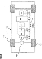
- FIG. 1 is a diagram showing a schematic configuration of a hybrid electric vehicle.
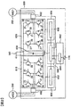
- FIG. 2 is a circuit diagram of the power converter.
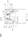
- FIG. 3 is a view showing a cross section of the rotating electrical machine.
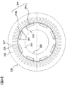
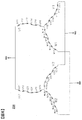
- FIG. 4 is a view showing a cross section of the stator and the rotor.
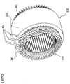
- FIG. 5 is a perspective view of the stator.
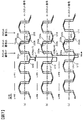
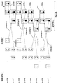
- FIG. 6 is a connection diagram of the stator winding.
- FIG. 7 is a diagram illustrating the U1-phase winding.
- FIG. 8 is a diagram showing a U2-phase winding.
- FIG. 9 is an enlarged view of a part of the U1-phase winding group.
- FIG. 10 is an enlarged view of a part of the U2-phase winding group.
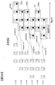
- FIG. 11 is a diagram showing the arrangement of slot conductors.
- FIG. 12 is a view showing the slot conductor arrangement of the first comparative example.
- FIG. 13 is a diagram for explaining the arrangement of slot conductors in the embodiment.
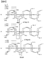
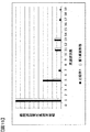
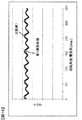
- FIG. 14 is a diagram illustrating an induced voltage waveform of the rotating electrical machine of the present embodiment and an induced voltage waveform of the rotating electrical machine of Comparative Example 1.
- FIG. 15 is a diagram illustrating harmonic analysis results regarding the induced voltage waveforms of the embodiment and the comparative example 1.
- FIG. 16 shows a torque waveform when an alternating current is applied in comparison between the embodiment and the first comparative example.
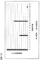
- FIG. 17 is a diagram showing harmonic analysis results of the torque waveforms shown in FIG.
- FIG. 18 shows a torque waveform when an alternating current is applied in comparison between the embodiment and the second comparative example.
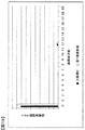
- FIG. 19 is a diagram showing harmonic analysis results of the torque waveforms shown in FIG.
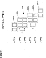
- FIG. 20 is a diagram showing the arrangement of slot conductors in Comparative Example 2.
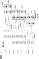
- FIG. 21 is a diagram illustrating a first modification.
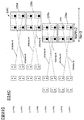
- FIG. 22 is a diagram illustrating a second modification.
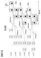
- FIG. 23 is a diagram showing a third modification.
- FIG. 24 is a diagram showing a fourth modification.
- FIG. 25 is a diagram showing a fifth modification.
- FIG. 26 is a diagram illustrating a sixth modification.
- FIG. 1 is a diagram showing a schematic configuration of a hybrid electric vehicle equipped with a rotating electrical machine according to an embodiment of the present invention.
- the vehicle 100 is mounted with an engine 120, a first rotating electrical machine 200, a second rotating electrical machine 202, and a battery 180.
- the battery 180 supplies DC power to the rotating electrical machines 200 and 202 via the power converter 600 when the driving force by the rotating electrical machines 200 and 202 is required, and receives DC power from the rotating electrical machines 200 and 202 during regenerative travel. . Transfer of direct-current power between the battery 180 and the rotating electrical machines 200 and 202 is performed via the power converter 600.
- the vehicle is equipped with a battery that supplies low-voltage power (for example, 14 volt system power) and supplies DC power to a control circuit described below.
- Rotational torque generated by the engine 120 and the rotating electrical machines 200 and 202 is transmitted to the front wheels 110 via the transmission 130 and the differential gear 160.
- the transmission 130 is controlled by a transmission control device 134.
- the engine 120 is controlled by the engine control device 124.
- the battery 180 is controlled by the battery control device 184.
- Transmission control device 134, engine control device 124, battery control device 184, power conversion device 600 and integrated control device 170 are connected by communication line 174.
- the integrated control device 170 is a higher-level control device than the transmission control device 134, the engine control device 124, the power conversion device 600, and the battery control device 184.
- the integrated control device 170 receives information representing the states of the transmission control device 134, the engine control device 124, the power conversion device 600, and the battery control device 184 from each of them via the communication line 174.
- the integrated control device 170 calculates a control command for each control device based on the acquired information. The calculated control command is transmitted to each control device via the communication line 174.
- the high voltage battery 180 is composed of a secondary battery such as a lithium ion battery or a nickel metal hydride battery, and outputs a high voltage DC power of 250 to 600 volts or more.
- the battery control device 184 outputs the charge / discharge status of the battery 180 and the state of each unit cell battery constituting the battery 180 to the integrated control device 170 via the communication line 174.
- the integrated control device 170 determines that the battery 180 needs to be charged based on the information from the battery control device 184, the integrated control device 170 instructs the power conversion device 600 to perform a power generation operation.
- the integrated control device 170 mainly manages the output torque of the engine 120 and the rotating electrical machines 200 and 202, and calculates the total torque and torque distribution ratio between the output torque of the engine 120 and the output torque of the rotating electrical machines 200 and 202. And a control command based on the calculation processing result is transmitted to the transmission control device 134, the engine control device 124, and the power conversion device 600.
- the power conversion device 600 controls the rotating electrical machines 200 and 202 so that torque output or generated power is generated as commanded.
- the power conversion device 600 is provided with a power semiconductor that constitutes an inverter for operating the rotating electric machines 200 and 202.
- the power conversion device 600 controls the switching operation of the power semiconductor based on a command from the integrated control device 170. By the switching operation of the power semiconductor, the rotary electric machines 200 and 202 are operated as an electric motor or a generator.
- DC power from the high voltage battery 180 is supplied to the DC terminal of the inverter of the power converter 600.
- the power conversion device 600 converts the DC power supplied by controlling the switching operation of the power semiconductor into three-phase AC power, and supplies it to the rotating electrical machines 200 and 202.
- the rotating electrical machines 200 and 202 are operated as a generator, the rotors of the rotating electrical machines 200 and 202 are rotationally driven with a rotational torque applied from the outside, and the stator windings of the rotating electrical machines 200 and 202 are three-phased. AC power is generated.
- the generated three-phase AC power is converted into DC power by the power converter 600, and the DC power is supplied to the high-voltage battery 180, whereby the battery 180 is charged.
- FIG. 2 shows a circuit diagram of the power conversion device 600 of FIG.
- the power conversion device 600 is provided with a first inverter device for the rotating electrical machine 200 and a second inverter device for the rotating electrical machine 202.
- the first inverter device includes a power module 610, a first drive circuit 652 that controls the switching operation of each power semiconductor 21 of the power module 610, and a current sensor 660 that detects the current of the rotating electrical machine 200.
- the drive circuit 652 is provided on the drive circuit board 650.
- the second inverter device includes a power module 620, a second drive circuit 656 that controls the switching operation of each power semiconductor 21 in the power module 620, and a current sensor 662 that detects the current of the rotating electrical machine 202.
- the drive circuit 656 is provided on the drive circuit board 654.
- the control circuit 648 provided on the control circuit board 646, the capacitor module 630, and the transmission / reception circuit 644 mounted on the connector board 642 are commonly used by the first inverter device and the second inverter device.
- the power modules 610 and 620 operate according to drive signals output from the corresponding drive circuits 652 and 656, respectively.
- the power modules 610 and 620 When operating the rotary electric machines 200 and 202 as electric motors, the power modules 610 and 620 respectively convert the DC power supplied from the battery 180 into three-phase AC power and use the electric power of the corresponding rotary electric machines 200 and 202. Supplied to the stator winding that is the child winding.
- the power modules 610 and 620 convert the AC power induced in the stator windings of the rotating electrical machines 200 and 202 into direct current, and the high voltage battery 180. To supply.
- the power modules 610 and 620 include a three-phase bridge circuit as shown in FIG. 2, and series circuits corresponding to the three phases are electrically connected in parallel between the positive electrode side and the negative electrode side of the battery 180, respectively. ing.
- Each series circuit includes a power semiconductor 21 constituting an upper arm and a power semiconductor 21 constituting a lower arm, and these power semiconductors 21 are connected in series.
- the power module 610 and the power module 620 have substantially the same circuit configuration as shown in FIG. 2, and the power module 610 will be described as a representative here.
- an IGBT (insulated gate bipolar transistor) 21 is used as a switching power semiconductor element.
- the IGBT 21 includes three electrodes, a collector electrode, an emitter electrode, and a gate electrode.
- a diode 38 is electrically connected between the collector electrode and the emitter electrode of the IGBT 21.
- the diode 38 includes two electrodes, a cathode electrode and an anode electrode.
- the cathode electrode is the collector electrode of the IGBT 21 and the anode electrode is the IGBT 21 so that the direction from the emitter electrode to the collector electrode of the IGBT 21 is the forward direction.
- Each is electrically connected to the emitter electrode.
- a MOSFET metal oxide semiconductor field effect transistor
- the MOSFET includes three electrodes, a drain electrode, a source electrode, and a gate electrode.
- a parasitic diode whose forward direction is from the drain electrode to the source electrode is provided between the source electrode and the drain electrode, so there is no need to provide the diode 38 of FIG.
- the arm of each phase is configured such that the emitter electrode of the IGBT 21 and the collector electrode of the IGBT 21 are electrically connected in series.
- the emitter electrode of the IGBT 21 and the collector electrode of the IGBT 21 are electrically connected in series.
- only one IGBT of each upper and lower arm of each phase is illustrated, but since the current capacity to be controlled is large, a plurality of IGBTs are actually connected in parallel. Has been. Below, in order to simplify description, it demonstrates as one power semiconductor.
- each upper and lower arm of each phase is composed of three IGBTs.
- the collector electrode of the IGBT 21 of each upper arm of each phase is electrically connected to the positive electrode side of the battery 180, and the source electrode of the IGBT 21 of each lower arm of each phase is electrically connected to the negative electrode side of the battery 180.
- the middle point of each arm of each phase (the connection portion between the emitter electrode of the upper arm side IGBT and the collector electrode of the IGBT on the lower arm side) is the armature winding (fixed) of the corresponding phase of the corresponding rotating electric machine 200, 202. Is electrically connected to the secondary winding.
- the drive circuits 652 and 656 constitute a drive unit for controlling the corresponding power modules 610 and 620, and generate a drive signal for driving the IGBT 21 based on the control signal output from the control circuit 648. To do.
- the drive signals generated by the drive circuits 652 and 656 are output to the gates of the power semiconductor elements of the corresponding power modules 610 and 620, respectively.
- Each of the drive circuits 652 and 656 is provided with six integrated circuits that generate drive signals to be supplied to the gates of the upper and lower arms of each phase, and the six integrated circuits are configured as one block.
- the control circuit 648 constitutes a control unit of each power module 610, 620, and is constituted by a microcomputer that calculates control signals (control values) for operating (turning on / off) a plurality of switching power semiconductor elements. ing.
- the control circuit 648 receives a torque command signal (torque command value) from the host controller, sensor outputs of the current sensors 660 and 662, and sensor outputs of the rotation sensors mounted on the rotating electrical machines 200 and 202.
- the control circuit 648 calculates a control value based on these input signals and outputs a control signal for controlling the switching timing to the drive circuits 652 and 656.
- the transmission / reception circuit 644 mounted on the connector board 642 is for electrically connecting the power conversion apparatus 600 and an external control apparatus, and communicates information with other apparatuses via the communication line 174 in FIG. Send and receive.
- Capacitor module 630 constitutes a smoothing circuit for suppressing fluctuations in the DC voltage caused by the switching operation of IGBT 21, and is electrically connected to the DC side terminal of first power module 610 or second power module 620. Connected in parallel.
- FIG. 3 shows a cross-sectional view of the rotating electric machine 200 of FIG.
- the rotating electrical machine 200 and the rotating electrical machine 202 have substantially the same structure, and the structure of the rotating electrical machine 200 will be described below as a representative example. However, the structure shown below does not need to be employed in both the rotating electrical machines 200 and 202, and may be employed in only one of them.
- a stator 230 is held inside the housing 212, and the stator 230 includes a stator core 232 and a stator winding 238.
- a rotor 250 is rotatably held on the inner peripheral side of the stator core 232 through a gap 222.
- the rotor 250 includes a rotor core 252 fixed to the shaft 218, a permanent magnet 254, and a non-magnetic contact plate 226.
- the housing 212 has a pair of end brackets 214 provided with bearings 216, and the shaft 218 is rotatably held by these bearings 216.
- the shaft 218 is provided with a resolver 224 that detects the pole position and rotation speed of the rotor 250.
- the output from the resolver 224 is taken into the control circuit 648 shown in FIG.
- the control circuit 648 outputs a control signal to the drive circuit 652 based on the fetched output.
- the drive circuit 652 outputs a drive signal based on the control signal to the power module 610.
- the power module 610 performs a switching operation based on the control signal, and converts DC power supplied from the battery 180 into three-phase AC power. This three-phase AC power is supplied to the stator winding 238 shown in FIG. 3 and a rotating magnetic field is generated in the stator 230.
- the frequency of the three-phase alternating current is controlled based on the output value of the resolver 224, and the phase of the three-phase alternating current with respect to the rotor 250 is also controlled based on the output value of the resolver 224.
- FIG. 4 is a cross-sectional view of the stator 230 and the rotor 250, and shows a cross-sectional view taken along the line AA of FIG.
- the housing 212, the shaft 218, and the stator winding 238 are not shown.
- On the inner peripheral side of the stator core 232 a large number of slots 237 and teeth 236 are arranged uniformly over the entire circumference.
- all slots and teeth are not labeled, and only some teeth and slots are represented by symbols.
- a slot insulating material (not shown) is provided in the slot 237, and a plurality of U-phase, V-phase, and W-phase windings constituting the stator winding 238 shown in FIG.
- 48 slots 237 are formed at equal intervals.
- a plurality of holes 253 for inserting rectangular magnets are arranged at equal intervals along the circumferential direction.
- Each hole 253 is formed along the axial direction, and permanent magnets 254 (254a, 254b) are embedded in the holes 253 and fixed with an adhesive or the like.
- the circumferential width of the hole 253 is set larger than the circumferential width of the permanent magnet 254, and the hole space 257 on both sides of the permanent magnet 254 functions as a magnetic gap.
- the hole space 257 may be filled with an adhesive, or may be solidified integrally with the permanent magnet 254 with a molding resin.
- the permanent magnet 254 acts as a field pole of the rotor 250 and has an eight-pole configuration in this embodiment.
- the magnetization direction of the permanent magnet 254 is in the radial direction, and the direction of the magnetization direction is reversed for each field pole. That is, if the stator side surface of the permanent magnet 254a is N-pole and the surface on the shaft side is S-pole, the stator side surface of the adjacent permanent magnet 254b is S-pole and the surface on the shaft side is N-pole. . These permanent magnets 254a and 254b are alternately arranged in the circumferential direction.
- the permanent magnet 254 may be inserted into the hole 253 after being magnetized, or may be magnetized by applying a strong magnetic field after being inserted into the hole 253 of the rotor core 252.
- the magnetized permanent magnet 254 is a strong magnet, if the magnet is magnetized before the permanent magnet 254 is fixed to the rotor 250, a strong attractive force between the rotor core 252 and the permanent magnet 254 is fixed. Occurs and hinders assembly work.
- due to the strong attractive force of the permanent magnet 254 dust such as iron powder may adhere to the permanent magnet 254. Therefore, when considering the productivity of the rotating electrical machine, it is preferable that the permanent magnet 254 is magnetized after being inserted into the rotor core 252.
- the permanent magnet 254 may be a neodymium-based or samarium-based sintered magnet, a ferrite magnet, a neodymium-based bond magnet, or the like.
- the residual magnetic flux density of the permanent magnet 254 is about 0.4 to 1.4T.
- the alternating current since the alternating current is controlled to be sinusoidal, the product of the fundamental wave component of the interlinkage magnetic flux and the fundamental wave component of the alternating current becomes the time-average component of the torque, and the harmonic component of the interlinkage magnetic flux
- the product of the fundamental wave components of the alternating current becomes the torque ripple that is the harmonic component of the torque. That is, in order to reduce the torque ripple, the harmonic component of the flux linkage may be reduced.
- the harmonic component of the linkage flux since the product of the linkage flux and the angular velocity of the rotor is the induced voltage, reducing the harmonic component of the linkage flux is equivalent to reducing the harmonic component of the induced voltage.
- FIG. 5 is a perspective view of the stator 230.
- the stator winding 238 is wound around the stator core 232 by wave winding. Coil ends 241 of the stator winding 238 are formed on both end surfaces of the stator core 232. Further, a lead wire 242 of the stator winding 238 is drawn out on one end face side of the stator core 232. The lead wire 242 is drawn out corresponding to each of the U phase, the V phase, and the W phase.
- FIG. 6 is a connection diagram of the stator winding 238, showing the connection method and the electrical phase relationship of each phase winding.
- the stator winding 238 of this embodiment employs a double star connection, and includes a first star connection composed of a U1-phase winding group, a V1-phase winding group, and a W1-phase winding group, and a U2-phase winding.
- a second star connection composed of a group, a V2-phase winding group, and a W2-phase winding group is connected in parallel.
- Each of the U1, V1, W1 phase winding group and the U2, V2, W2 phase winding group is composed of six rotating windings, and the U1 phase winding group has rotating windings U11 to U16, and the V1 phase
- the winding group has circumferential windings V11 to V16
- the W1 phase winding group has circumferential windings W11 to W16
- the U2 phase winding group has circumferential windings U21 to U26
- the group has circular windings V21 to V26
- the W2-phase winding group has circular windings W21 to W26.
- the V phase and the W phase have substantially the same configuration as the U phase, and are arranged so that the phase of the voltage induced in each phase is shifted by 120 degrees in electrical angle.
- the angles of the respective windings represent relative phases.
- the stator winding 238 employs a double star (2Y) connection connected in parallel. However, depending on the driving voltage of the rotating electrical machine, they may be connected in series. It may be a star (1Y) connection.
- FIGS. 7 and 8 are diagrams showing the detailed connection of the U-phase winding of the stator winding 238.
- the stator core 232 is formed with 48 slots 237 (see FIG. 4), and reference numerals 01, 02,..., 47, 48 shown in FIGS. .
- FIG. 7A shows the windings U15 and U16 of the U1-phase winding group.
- FIG. 7B shows the windings U13 and U14 of the U1-phase winding group.
- FIG. 7C shows the windings U11 and U12 of the U1-phase winding group.
- FIG. 8 (a) shows the windings U21 and 22 of the U2-phase winding group.
- FIG. 8B shows the windings U23 and U24 of the U2-phase winding group.
- FIG. 8C shows the windings U25 and U26 of the U2-phase winding group.
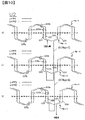
- each of the windings U11 to U26 connects the end portions on the same side of the slot conductor 233a inserted in the slot and the slot conductor 233a inserted in a different slot, It consists of a transition conductor 233b that constitutes the coil end 241 (see FIG. 5).
- the upper end portion of the slot conductor 233a in the figure is formed by the crossing conductor 233b constituting the upper coil end. Is connected to the upper end of the slot conductor 233a inserted through the slot 237.
- the lower end portion of the slot conductor 233a is connected to the lower end portion of the slot conductor 233a inserted into the slot 237 of the slot number 11 by the transition conductor 233b constituting the lower coil end.
- the slot conductor 233a is connected by the crossing conductor 233b, so that a wave winding coil that substantially goes around the stator core 232 is formed.
- the portions of the windings U15, U16, U21, and U22 that are represented by solid lines indicate the layer 1, and the portions that are represented by broken lines indicate the layer 2.
- the portion represented by the solid line indicates the layer 3, and the portion represented by the broken line indicates the layer 4.
- the part represented by a solid line represents the layer 5, and the part represented by a broken line represents the layer 6.
- the circular windings U11 to U26 may be formed of a continuous conductor, or the segment coils may be connected to each other by welding after the segment coils are inserted into the slots.
- the coil ends 241 positioned at both ends in the axial direction from the end of the stator core 232 can be formed in advance. The insulation distance can be easily provided. As a result, partial discharge due to a surge voltage generated by the switching operation of the IGBT 21 can be suppressed, which is effective for insulation.
- the conductor used for the circular winding may be a conductor having a large number of flat wires, round wires, or thin wires, but in order to increase the space factor for the purpose of miniaturization and high output, Line is suitable.
- FIG. 9 is an enlarged view of a part of the U1-phase winding group shown in FIG.
- FIG. 10 is an enlarged view of a part of the U2-phase winding group shown in FIG. 9 and 10 show about four poles including a jumper wire portion.
- the winding method of the U1-phase winding group will be described with reference to FIG. 9, and the winding method of the U2-phase winding group will be described with reference to FIG.
- the circumferential winding U11 of the stator winding group U1 enters the layer 6 of the slot number 01 from the lead wire, and is equivalent to 6 slots (that is, 6 slots pitch) by the crossing conductor 233b. Then, the slot conductor 233a enters the layer 5 of the slot number 07. Next, from layer 5 of slot number 07, layer 6 of slot number 13 is entered across 6 slots.
- the stator winding for approximately one turn so far is the circular winding U11 shown in FIG.
- the stator winding coming out from layer 5 of slot number 43 enters layer 6 of slot number 48 across five slots.
- the circular winding U12 shown in FIG. 6 is formed.
- the winding is wound with a wave winding. The stator winding for approximately one turn so far is the circular winding U12.
- the circumferential winding U12 is wound with a one-slot pitch shift with respect to the circumferential winding U11, so that a phase difference corresponding to one slot pitch is generated.
- one slot pitch corresponds to an electrical angle of 30 degrees, and in FIG. 6 as well, the circumferential winding U11 and the circumferential winding U12 are described as being shifted by 30 degrees.
- the stator winding coming out from layer 3 with slot number 42 enters layer 4 with slot number 47 across five slots. From the layer 4 of the slot number 47, it becomes the circular winding U14 shown in FIG.
- the winding is wound with a wave winding. The stator winding for approximately one turn so far is the circular winding U14.
- one slot pitch corresponds to an electrical angle of 30 degrees
- the circumferential winding U13 and the circumferential winding U14 are described as being shifted by 30 degrees.
- the stator winding coming out from the layer 3 of the slot number 41 is connected to the layer of the slot number 48 via the jumper wire J1 having a spanning amount Npj of 7 slot pitch. Enter 2.
- the circular winding U15 shown in FIG. 6 is obtained.
- the winding is wound with a wave winding.
- the stator winding for approximately one turn so far is the circular winding U15.
- the stator winding coming out from layer 1 with slot number 42 enters layer 2 with slot number 47 across five slots. From the layer 2 of the slot number 47, it becomes the circular winding U16 shown in FIG.
- the winding is wound with a wave winding. The stator winding for approximately one turn so far is the circular winding U16.
- one slot pitch corresponds to an electrical angle of 30 degrees
- the circumferential winding U15 and the circumferential winding U16 are described as being shifted by 30 degrees.
- the circumferential winding U12 and the circumferential winding U13 are connected by the jumper wire J2 having a spanning amount Npj of 6 slot pitch. Therefore, the circumferential winding U13 is wound around the circumferential winding U11 by shifting by one slot pitch, and a phase difference corresponding to an electrical angle corresponding to one slot pitch is generated.
- one slot pitch corresponds to an electrical angle of 30 degrees
- the circumferential winding U11 and the circumferential winding U13 are described as being shifted by 30 degrees.
- the circumferential winding U14 is wound around the circumferential winding U12 with a shift of one slot pitch.
- the circumferential winding U14 and the circumferential winding U15 are connected by a jumper wire J1 having a spanning amount Npj of 7 slot pitch. Therefore, the circumferential winding U15 is wound in the same slot as the circumferential winding U13, and no phase difference is generated. Also in FIG. 6, the windings U13 and U15 are shown without being shifted in angle. Similarly, the winding winding U16 is wound in the same slot as the winding winding U14.
- the stator winding group U2 shown in FIG. 10 is also wound with the same straddling amount as in the case of each layer of the stator winding group U1.
- Circumferential winding U21 is wound from layer 1 of slot number 47 to layer 2 of slot number 05. Thereafter, straddling 5 slots, entering layer 1 of slot number 48, and winding winding U22 is wound from layer 1 of slot number 48 to layer 2 of slot number 06.
- stator winding enters layer 3 of slot number 47 from layer 2 of slot number 06 via jumper wire J1 having a spanning amount Npj of 7 slot pitch, and winds up to layer 4 of slot number 05 as circular winding U23. Turned. Thereafter, straddling 5 slots and entering layer 3 of slot number 48, and the winding winding U24 is wound from layer 3 of slot number 48 to layer 4 of slot number 06.
- stator winding enters the layer 5 of the slot number 48 from the layer 4 of the slot number 06 through the jumper wire J2 having a spanning amount Npj of 6 slot pitch, and goes to the layer 6 of the slot number 06 as the circular winding U25. It is wound. Thereafter, the circular winding U26 is wound from the layer 5 of the slot number 01 to the layer 6 of the slot number 07.
- the stator winding group U1 is composed of the windings U11, U12, U13, U14, U15, and U16, and a voltage obtained by synthesizing the respective phases is induced in the stator winding group U1.
- a voltage in which the phases of the windings U21, U22, U23, U24, U25, and U26 are combined is induced.
- stator winding group U1 and the stator winding group U2 are connected in parallel, but there is a phase difference between the voltages induced in the stator winding groups U1 and U2. There is no imbalance such as circulating current flowing even in parallel connection. Of course, it may be connected in series.
- FIG. 11 is a diagram mainly showing the arrangement of the slot conductors 233a in the stator core 232, and shows slot numbers 46 to 13 in FIGS.
- the rotation direction of the rotor is from the left to the right in the figure.
- twelve slots 237 are arranged for two poles, that is, an electrical angle of 360 degrees.
- six slot conductors 233a of the stator winding 238 are inserted.
- Each slot conductor 233a is indicated by a rectangle.
- symbols U11 to U26, V and W indicating the U phase, V phase and W phase, a cross mark “X” indicating the direction from the side where the lead wire is located to the opposite side, and the opposite direction are indicated.
- the black circles “ ⁇ ” shown are respectively shown.
- the slot conductor 233a located on the innermost side (slot opening side) of the slot 237 is referred to as layer 1, and is called layer 2, layer 3, layer 4, layer 5, and layer 6 in order from the outer side (slot bottom side). I will decide.
- Reference numerals 01 to 12 are slot numbers similar to those shown in FIGS. Note that only the U-phase slot conductor 233a is indicated by reference numerals U11 to U26 representing the circular winding, and the V-phase and W-phase slot conductors 233a are indicated by reference signs V and W indicating the phases.
- twelve slot conductors 233a surrounded by a broken line 234 are a slot conductor group 234 made up of U-phase slot conductors 233a.
- the slot conductor group 234 shown in the center includes the slot conductors 233a of the windings U25, U26, U12, U11 disposed in the layers 6 to 5 of the slot numbers 06 and 07 and the layers of the slot numbers 05 and 06. 4 and the slot conductor 233a of the surrounding windings U23, U24, U14, U13, U21, U22, U16, U15 disposed from the layer 1 to the layer 1.
- the number N of slots per pole is 6, the number of slots NSPP per pole is 2, and the number of layers of the slot conductors 233a in the slots 237 is 6, as shown in FIG.
- a configuration in which slot conductors 233a of the same phase are arranged is employed.
- the jumping amount Npj of the jumper line connecting the slot conductor 233a of layer 2 and the slot conductor 233a of layer 3 is 7 slot pitch
- the jumping amount of jumper line connecting the slot conductor 233a of layer 4 and the slot conductor 233a of layer 5 Npj is also 7 slot pitch.
- the configuration of the present embodiment has four slot conductors 233a of layer 5 and layer 6 shown in FIG. 12 corresponding to one slot pitch in the rotation direction of the rotor (right direction in the figure). It has a shifted configuration.
- the straddling amount Npj of the jumper wire J2 connecting the slot conductor 233a of the layer 4 and the slot conductor 233a of the layer 5 becomes 6 slot pitch, and the jumper wire connecting the slot conductor 233a of the layer 2 and the slot conductor 233a of the layer 3
- the stride amount Npj of J1 is 7 slot pitch.
- a slot conductor group 234 having a shape is formed. That is, with respect to the rotation direction of the rotor, a slot conductor group consisting of slot conductors 233a with U-phase cross marks, a slot conductor group consisting of slot conductors 233a with black circles on W-phases, and slot signs with V-phase cross marks.
- Slot conductor group consisting of conductors 233a slot conductor group consisting of slot conductors 233a with black circles in the U phase, slot conductor group consisting of slot conductors 233a with cross marks in the W phase, slots consisting of slot conductors 233a with black circles in the V phase A conductor group is arranged.
- n a natural number from 1 to NL
- the winding is inserted into layers 2n-1 and 2n.
- NL 3
- a line connecting the windings different in the radial direction is a jumper wire.
- the jumping amount Npj includes one having an (N + 1) slot pitch and one having a ⁇ (N + 1) ⁇ 1 ⁇ slot pitch.
- the number N of slots per pole is 6, and the 7-slot pitch jumper wire J1 corresponds to the (N + 1) slot pitch jumper wire, and the 6-slot pitch jumper wire J2 is ⁇ It corresponds to a jumper wire of (N + 1) -1 ⁇ slot pitch.
- the slot conductor group 234 of this embodiment will be further described with reference to FIG.
- the slot conductor group 234 can be divided into slot conductor subgroups 235 (235a, 235b, 235c) indicated by broken lines in FIG.
- the slot conductor small group 235 includes a slot conductor 233a inserted in the inner peripheral layer adjacent to the stator core 232 in the radial direction and connected to the conductor 233b, and a slot conductor 233a inserted in the outer peripheral layer. It is configured.
- the jumper wire is provided between the inner peripheral side layer of the slot conductor small group 235 and the outer peripheral side layer of the slot conductor small group 235 adjacent in the radial direction. For example, a jumper wire is provided between the layer 5 of the slot conductor small group 235c and the layer 4 of the slot conductor small group 235b.
- the slot conductor subgroup 235a and the slot conductor subgroup 235b are aligned in the circumferential direction.
- the jumping amount Npj of the jumper line J1 is 7 slot pitch, that is, (N + 1) slot pitch.
- the slot conductor small group 235c is shifted by one slot pitch in the rotational direction (right direction in the drawing) with respect to the adjacent slot conductor small group 235b, so that the inner peripheral side of the slot conductor small group 235c connected by the jumper wire J2
- the layer and the outer peripheral side layer of the slot conductor small group 235b are shifted by one slot pitch. Therefore, as can be seen from FIG. 9, the straddling amount Npj of the jumper line J2 is 6 slot pitches, ie, ⁇ (N + 1) ⁇ 1 ⁇ slot pitch, which is 1 slot pitch smaller than that of the jumper line J1.
- the straddling amount Npj of the jumper line J2 is the case of the jumper line J1.
- the stator winding of each phase includes the slot conductor group 234 including a plurality of slot conductors 233a inserted into the predetermined number of slots Ns arranged continuously in the circumferential direction of the stator core, And a transition conductor 233b for connecting the coil end side of the slot conductor 233a.
- the plurality of slot conductors 233a included in one slot conductor group 234 are arranged so that the slots and layers through which the slot conductors 233a are inserted are adjacent to each other.
- the slot conductor small group 235b is shifted by one slot pitch to the left in the figure with respect to the slot conductor small group 235a, and the slot conductor small group 235c is illustrated with respect to the slot conductor small group 235b.
- the slot conductor 233a of layer 2 and the slot conductor 233a of layer 3 connected by the jumper wire J1 are inserted into the same slot, and the circumferential positions thereof are the same. Therefore, the jumping amount Npj of the jumper line J1 is (N + 1).
- the straddling amount Npj of the jumper line J2 is (N + 1).
- FIG. 14 is a diagram illustrating an induced voltage waveform of the rotating electrical machine of the present embodiment and an induced voltage waveform of the rotating electrical machine of Comparative Example 1.
- FIG. 15 shows the result of harmonic analysis of each induced voltage waveform of FIG.
- FIG. 16 shows torque waveforms when an alternating current is applied for the rotating electrical machine of the present embodiment and the rotating electrical machine of Comparative Example 1.
- FIG. 17 shows the result of harmonic analysis of each torque waveform shown in FIG. As shown in the harmonic analysis result of FIG. 17, it has been found that, in particular, sixth-order torque ripple can be reduced.
- the slot conductors 233a are arranged so that the jumper wire straddling amount Npj includes the (N + 1) slot pitch and the ⁇ (N + 1) ⁇ 1 ⁇ slot pitch. It is shown that the induced voltage, that is, the fifth-order and seventh-order components of the interlinkage magnetic flux are reduced by arranging.
- FIG. 18 and FIG. 19 compare the operational effects of the present embodiment with those of Comparative Example 2.
- FIG. 18 shows torque waveforms when an alternating current is applied for the rotating electrical machine of this embodiment and for the rotating electrical machine of Comparative Example 2.
- FIG. 19 shows the result of harmonic analysis of each torque waveform shown in FIG. As shown in FIGS. 18 and 19, it was found that the average torque is larger in this embodiment than in Comparative Example 2.
- the rotating electrical machine of the present embodiment can provide a rotating electrical machine with high torque and low noise. Moreover, in a vehicle equipped with the rotating electrical machine, it is possible to achieve high torque and low noise.
- FIG. 21 is a diagram showing a first modification of the above-described embodiment, and shows a slot conductor group 234B.
- the number of layers is eight.
- the slot conductor group 234B is composed of four slot conductor subgroups 235a to 235d.
- the slot conductor subgroups 235b and 235c are shifted by one slot pitch to the right of the slot conductor subgroup 235a, and the slot conductor subgroup 235d is illustrated with respect to the slot conductor subgroups 235b and 235c.
- the jumping amount Npj of the jumper line connecting the slot conductor 233a of the layer 4 and the slot conductor 233a of the layer 5 is 7 slot pitch.
- Npj the number of slots
- N 6 per pole.
- ⁇ (N + 1) -1 ⁇ slot pitch jumper wires.
- each phase winding is configured such that the straddling amount Npj includes a jumper wire having an (N + 1) slot pitch and a jumper wire having a ⁇ (N + 1) -1 ⁇ slot pitch. Similar to the embodiment, the torque ripple is smaller and the noise is lower than that of the first comparative example, and the average torque is larger than that of the second comparative example.
- FIG. 22 is a view showing a slot conductor group 234C in the second modification.
- the slot conductor small groups 235c and 235d are shifted by one slot pitch on the right side of the figure with respect to the slot conductor small groups 235a and 235b.
- the jumping amount Npj of the jumper line connecting the slot conductor 233a of layer 4 and the slot conductor 233a of layer 5 is set to 6 slot pitch
- the jumping amount Npj of the jumper line connecting the slot conductor 233a of the layer 6 and the slot conductor 233a of the layer 7 is set to 7 slot pitch, respectively.
- each phase winding is configured such that the straddling amount Npj includes a jumper wire having an (N + 1) slot pitch and a jumper wire having a ⁇ (N + 1) ⁇ 1 ⁇ slot pitch. Therefore, similarly to the above-described embodiment, the effect that the torque ripple is smaller and the noise is lower than that of the first comparative example, and the average torque is larger than that of the second comparative example.
- the slot conductor small group 235d may be shifted by two slot pitches on the right side in the figure with respect to the slot conductor small groups 235a and 235b, and three types of jumper wires may be provided.
- FIG. 23 shows a slot conductor group 234D in the third modification.
- the circumferential directions of the slot conductor small groups 235a and 235b are the same, and the slot conductor small group 235c is shifted by one slot pitch to the right in the figure with respect to the slot conductor small groups 235a and 235b. . Therefore, the jumping amount Npj of the jumper wire connecting the layer 4 slot conductor 233a and the layer 5 slot conductor 233a becomes ⁇ (N + 1) ⁇ 1 ⁇ slot pitch, and the layer 2 slot conductor 233a and the layer 3 slot conductor 233a The jump amount Npj of the jumper line connecting the two becomes (N + 1) slot pitch.
- each phase winding is configured such that the straddling amount Npj includes the jumper wire having the (N + 1) slot pitch and the jumper wire having the ⁇ (N + 1) ⁇ 1 ⁇ slot pitch. Therefore, similarly to the above-described embodiment, the effect that the torque ripple is smaller and the noise is lower than that of the first comparative example, and the average torque is larger than that of the second comparative example.
- the rotating electrical machine of the present embodiment has the following configuration and exhibits the following operational effects.
- the stator winding 238 in the rotating electrical machine 200 (same for the rotating electrical machine 202) is wound in a wave winding so that the slot conductor 233a, which is a winding conductor, is inserted into each of the plurality of slots 237 by six layers or more.
- a plurality of rotating windings are provided.
- the stator winding 238 has a plurality of jumper wires for connecting the windings with different layers to be inserted.
- the plurality of jumper wires have jumper wires J1 having a spanning amount Npj of (N + 1) slot pitch when the windings are connected across the slots 237, ⁇ ( N + 1) ⁇ 1 ⁇ including a jumper wire J2 having a slot pitch.
- the slot conductor group 234 composed of a plurality of slot conductors 233a of the same phase is not displaced in the circumferential direction of the stator core.
- the conductor small group 235b and the slot conductor small group 235a shifted in the circumferential direction by one slot pitch are formed.
- the number of predetermined slots is Ns
- the number of slots per pole is NSPP
- the number of jumpers with a straddling amount Npj of ⁇ (N + 1) ⁇ 1 ⁇ slot pitch is 2 ⁇
- Ns NSPP + NJ holds. That is, with such a configuration, it is possible to achieve high torque and low noise in the rotating electrical machine.
- FIG. 24 is a view showing a slot conductor group 234E in the fourth modification.
- the outer layer of each of the slot conductor small groups 235a to 235c is shifted by one slot pitch in the rotation direction (right direction in the drawing) with respect to the inner layer.
- the spanning amount Np of the transition conductor 233b on the coil end side (lower side in the drawing) from which the lead wire is drawn out in the winding is 7 slot pitch, and the spanning of the transition conductor 233b on the opposite coil end side (upper side in the drawing).
- the quantity Np is 5 slot pitch.
- the modified example 4 is different from the above-described embodiment and modified examples 1 to 3 in that it is wound with such an irregular slot pitch wave winding.
- the slot conductor 233a of the layer 4 and the slot conductor 233a of the layer 5 have the same circumferential position. Therefore, the jumping amount Npj of the jumper line connecting the slot conductor 233a of the layer 4 and the slot conductor 233a of the layer 5 is set to the slot pitch when the number of slots per pole is N (N + 1).
- the slot conductor 233a of the layer 3 is shifted from the slot conductor 233a of the layer 2 by one slot pitch on the left side in the drawing. Therefore, the jumping amount Npj of the jumper line connecting the slot conductor 233a of the layer 2 and the slot conductor 233a of the layer 3 is set to ⁇ (N + 1) +1 ⁇ slot pitch.
- the circumferential winding is wound with an irregular slot pitch wave winding, and the predetermined number of slots Ns is 4.
- NSPP is the number of slots per phase per pole
- 2 ⁇ NL is the number of layers
- 2 ⁇ NJ is the number of jumper lines per phase where the straddle amount Npj is ⁇ (N + 1) +1 ⁇ slot pitch. .
- FIG. 25 is a diagram showing a slot conductor group 234F in the fifth modification.
- the slot conductor 233a of the layer 3 is shifted by one slot pitch to the left in the drawing with respect to the slot conductor 233a of the layer 2, and therefore, when the number of slots per pole is N, the jumper line straddling amount Npj is ⁇ (N + 1) +1 ⁇ slot pitch.
- the jumper line connecting the layer 6 and the layer 7 also has a straddling amount Npj of ⁇ (N + 1) +1 ⁇ slot pitch.
- the slot conductor 233a of the layer 4 and the slot conductor 233a of the layer 5 coincide with each other in the circumferential direction, so that the jump amount Npj of the jumper line connecting the layer 4 and the layer 5 is (N + 1).
- the number N of slots per pole is 6, so ⁇ (N + 1) +1 ⁇ is 8 and (N + 1) is 7.
- FIG. 26 is a diagram showing a slot conductor group 234G in the sixth modification.
- Each of the slot conductor subgroups 235a to 235c includes six slot conductors 233a.
- the circumferential positions of the slot conductor subgroups 235a and 235b are the same, and the slot conductor subgroup 235c is shifted by one slot pitch to the right in the figure with respect to the slot conductor subgroup 235b. Therefore, the slot conductor 233a of the layer 3 is shifted by one slot pitch on the left side in the drawing with respect to the slot conductor 233a of the layer 2.
- the slot conductor 233a of the layer 4 and the slot conductor 233a of the layer 5 have the same circumferential position.
- the jump amount Npj of the jumper line connecting layer 2 and layer 3 is ⁇ (N + 1) +1 ⁇ slot pitch
- the jump amount Npj of the jumper line connecting layer 4 and layer 5 is (N + 1) slot pitch.
- the jumper line straddling amount Npj includes ⁇ (N + 1) +1 ⁇ slot pitch and (N + 1) slot pitch.
- the stator winding 238 has a plurality of groups of slot conductor groups 234 including a plurality of slot conductors 233a of the same phase.
- a plurality of slot conductors 233a constituting 234 are inserted so that slots and layers are adjacent to a predetermined number Ns of slots 237 arranged continuously in the circumferential direction of the stator core.
- Ns the number of slots per phase per pole
- the number of layers is 2 ⁇ NL
- the number of jumper wires per slot pitch (N + 1) ⁇ 1 is defined as 2 ⁇ NJ
- Ns NSPP + NL-NJ
- the present invention is not limited to this.
- the same effect can be applied to windings having 3 or more NSPPs, 8 or more even layers, and both normal windings and windings wound with irregular slot pitch wave windings. Play.
Landscapes
- Engineering & Computer Science (AREA)
- Power Engineering (AREA)
- Windings For Motors And Generators (AREA)
Abstract
高トルク化および低騒音化を図ることができる回転電機の提供。 回転電機用の固定子は、1つのスロットにスロット導体が6個以上挿入される回転電機用の固定子において、 径方向において位置が異なる周回巻線を繋ぐジャンパー線のスロットピッチは少なくとも2種類以上の異なるスロットピッチでスロットを跨ぐ。
Description
本発明は、回転電機および車両に関する。
車両の駆動用として用いられる回転電機の巻線技術としては、特許文献1に記載のような技術が知られている。
ところで、電気自動車等に搭載される回転電機には、高トルクでありながら低騒音であることが要求されている。そのため、本発明は、高トルクかつ低騒音である回転電機を提供することを目的としている。
本発明の第1の態様によると、回転電機は、複数のスロットが形成された固定子コアと、巻線導体が複数の前記スロットの各々に6レイヤ以上挿通されるように、波巻で巻き回される周回巻線を複数有する固定子巻線と、前記固定子コアに対して回転自在に設けられた回転子と、を備え、前記固定子巻線は、挿通されるレイヤが異なる2つの前記周回巻線を接続するジャンパー線を複数有し、複数の前記ジャンパー線は、毎極スロット数をNとしたとき、前記スロットを跨いで前記2つの周回巻線を接続する際の跨ぎ量が(N+1)スロットピッチであるジャンパー線と、{(N+1)±1}スロットピッチであるジャンパー線とを含む。
本発明の第2の態様によると、車両は、前記回転電機と、直流電力を供給するバッテリと、前記バッテリの直流電力を交流電力に変換して前記回転電機に供給する変換装置と、を備え、前記回転電機のトルクを駆動力として用いる。
本発明の第2の態様によると、車両は、前記回転電機と、直流電力を供給するバッテリと、前記バッテリの直流電力を交流電力に変換して前記回転電機に供給する変換装置と、を備え、前記回転電機のトルクを駆動力として用いる。
本発明によれば、回転電機の高トルク化および低騒音化を図ることができる。
図1は、本発明の一実施形態の回転電機を搭載したハイブリッド型電気自動車の概略構成を示す図である。車両100には、エンジン120と第1の回転電機200と第2の回転電機202とバッテリ180とが搭載されている。バッテリ180は、回転電機200,202による駆動力が必要な場合には電力変換装置600を介して回転電機200,202に直流電力を供給し、回生走行時には回転電機200,202から直流電力を受ける。バッテリ180と回転電機200,202との間の直流電力の授受は、電力変換装置600を介して行われる。また、図示していないが、車両には低電圧電力(例えば、14ボルト系電力)を供給するバッテリが搭載されており、以下に説明する制御回路に直流電力を供給する。
エンジン120および回転電機200,202による回転トルクは、変速機130とデファレンシャルギア160を介して前輪110に伝達される。変速機130は変速機制御装置134により制御される。エンジン120はエンジン制御装置124により制御される。バッテリ180は、バッテリ制御装置184により制御される。変速機制御装置134、エンジン制御装置124、バッテリ制御装置184、電力変換装置600および統合制御装置170は、通信回線174によって接続されている。
統合制御装置170は、変速機制御装置134、エンジン制御装置124、電力変換装置600およびバッテリ制御装置184よりも上位の制御装置である。統合制御装置170は、変速機制御装置134,エンジン制御装置124,電力変換装置600およびバッテリ制御装置184の各状態を表す情報を、通信回線174を介してそれらからそれぞれ受け取る。統合制御装置170は、取得したそれらの情報に基づき各制御装置の制御指令を演算する。演算された制御指令は通信回線174を介してそれぞれの制御装置へ送信される。
高電圧のバッテリ180はリチウムイオン電池あるいはニッケル水素電池などの2次電池で構成され、250ボルトから600ボルト、あるいはそれ以上の高電圧の直流電力を出力する。バッテリ制御装置184は、バッテリ180の充放電状況やバッテリ180を構成する各単位セル電池の状態を、通信回線174を介して統合制御装置170に出力する。
統合制御装置170は、バッテリ制御装置184からの情報に基づいてバッテリ180の充電が必要と判断すると、電力変換装置600に発電運転の指示を出す。また、統合制御装置170は、主に、エンジン120および回転電機200,202の出力トルクの管理、エンジン120の出力トルクと回転電機200,202の出力トルクとの総合トルクやトルク分配比の演算処理を行い、その演算処理結果に基づく制御指令を、変速機制御装置134,エンジン制御装置124および電力変換装置600へ送信する。電力変換装置600は、統合制御装置170からのトルク指令に基づき、指令通りのトルク出力あるいは発電電力が発生するように回転電機200,202を制御する。
電力変換装置600には、回転電機200,202を運転するためのインバータを構成するパワー半導体が設けられている。電力変換装置600は、統合制御装置170からの指令に基づきパワー半導体のスイッチング動作を制御する。このパワー半導体のスイッチング動作により、回転電機200,202は電動機としてあるいは発電機として運転される。
回転電機200,202を電動機として運転する場合は、高電圧のバッテリ180からの直流電力が電力変換装置600のインバータの直流端子に供給される。電力変換装置600は、パワー半導体のスイッチング動作を制御して供給された直流電力を3相交流電力に変換し、回転電機200,202に供給する。一方、回転電機200,202を発電機として運転する場合には、回転電機200,202の回転子が外部から加えられる回転トルクで回転駆動され、回転電機200,202の固定子巻線に3相交流電力が発生する。発生した3相交流電力は電力変換装置600で直流電力に変換され、その直流電力が高電圧のバッテリ180に供給されることにより、バッテリ180が充電される。
図2は、図1の電力変換装置600の回路図を示す。電力変換装置600には、回転電機200のための第1のインバータ装置と、回転電機202のための第2のインバータ装置とが設けられている。第1のインバータ装置は、パワーモジュール610と、パワーモジュール610の各パワー半導体21のスイッチング動作を制御する第1の駆動回路652と、回転電機200の電流を検知する電流センサ660とを備えている。駆動回路652は駆動回路基板650に設けられている。
一方、第2のインバータ装置は、パワーモジュール620と、パワーモジュール620における各パワー半導体21のスイッチング動作を制御する第2の駆動回路656と、回転電機202の電流を検知する電流センサ662とを備えている。駆動回路656は駆動回路基板654に設けられている。制御回路基板646に設けられた制御回路648、コンデンサモジュール630およびコネクタ基板642に実装された送受信回路644は、第1のインバータ装置と第2のインバータ装置とで共通に使用される。
パワーモジュール610,620は、それぞれ対応する駆動回路652,656から出力された駆動信号によって動作する。回転電機200,202を電動機として運転する場合は、パワーモジュール610,620は、それぞれバッテリ180から供給された直流電力を三相交流電力に変換し、その電力を対応する回転電機200,202の電機子巻線である固定子巻線に供給する。また、回転電機200,202を発電機として運転する場合には、パワーモジュール610,620は、回転電機200,202の固定子巻線に誘起された交流電力を直流に変換し、高電圧バッテリ180に供給する。
パワーモジュール610,620は図2に記載のごとく3相ブリッジ回路を備えており、3相に対応した直列回路が、それぞれバッテリ180の正極側と負極側との間に電気的に並列に接続されている。各直列回路は上アームを構成するパワー半導体21と下アームを構成するパワー半導体21とを備え、それらのパワー半導体21は直列に接続されている。パワーモジュール610とパワーモジュール620とは、図2に示す如く回路構成がほぼ同じであり、ここではパワーモジュール610で代表して説明する。
本実施の形態では、スイッチング用パワー半導体素子としてIGBT(絶縁ゲート型バイポーラトランジスタ)21を用いている。IGBT21は、コレクタ電極,エミッタ電極及びゲート電極の3つの電極を備えている。IGBT21のコレクタ電極とエミッタ電極との間にはダイオード38が電気的に接続されている。ダイオード38は、カソード電極及びアノード電極の2つの電極を備えており、IGBT21のエミッタ電極からコレクタ電極に向かう方向が順方向となるように、カソード電極がIGBT21のコレクタ電極に、アノード電極がIGBT21のエミッタ電極にそれぞれ電気的に接続されている。
なお、スイッチング用パワー半導体素子として、MOSFET(金属酸化物半導体型電界効果トランジスタ)を用いてもよい。MOSFETは、ドレイン電極,ソース電極及びゲート電極の3つの電極を備えている。MOSFETの場合には、ソース電極とドレイン電極との間に、ドレイン電極からソース電極に向かう方向が順方向となる寄生ダイオードを備えているので、図2のダイオード38を設ける必要がない。
各相のアームは、IGBT21のエミッタ電極とIGBT21のコレクタ電極とが電気的に直列に接続されて構成されている。なお、本実施の形態では、各相の各上下アームのIGBTを1つしか図示していないが、制御する電流容量が大きいので、実際には複数のIGBTが電気的に並列に接続されて構成されている。以下では、説明を簡単にするため、1個のパワー半導体として説明する。
図2に示す例では、各相の各上下アームはそれぞれ3個のIGBTによって構成されている。各相の各上アームのIGBT21のコレクタ電極はバッテリ180の正極側に、各相の各下アームのIGBT21のソース電極はバッテリ180の負極側にそれぞれ電気的に接続されている。各相の各アームの中点(上アーム側IGBTのエミッタ電極と下アーム側のIGBTのコレクタ電極との接続部分)は、対応する回転電機200,202の対応する相の電機子巻線(固定子巻線)に電気的に接続されている。
駆動回路652,656は、対応するパワーモジュール610,620を制御するための駆動部を構成しており、制御回路648から出力された制御信号に基づいて、IGBT21を駆動させるための駆動信号を発生する。それぞれの駆動回路652,656で発生した駆動信号は、対応するパワーモジュール610,620の各パワー半導体素子のゲートにそれぞれ出力される。駆動回路652,656には、各相の各上下アームのゲートに供給する駆動信号を発生する集積回路がそれぞれ6個設けられており、6個の集積回路を1ブロックとして構成されている。
制御回路648は各パワーモジュール610,620の制御部を構成しており、複数のスイッチング用パワー半導体素子を動作(オン・オフ)させるための制御信号(制御値)を演算するマイクロコンピュータによって構成されている。制御回路648には、上位制御装置からのトルク指令信号(トルク指令値)、電流センサ660,662のセンサ出力、回転電機200,202に搭載された回転センサのセンサ出力が入力される。制御回路648はそれらの入力信号に基づいて制御値を演算し、駆動回路652,656にスイッチングタイミングを制御するための制御信号を出力する。
コネクタ基板642に実装された送受信回路644は、電力変換装置600と外部の制御装置との間を電気的に接続するためのもので、図1の通信回線174を介して他の装置と情報の送受信を行う。コンデンサモジュール630は、IGBT21のスイッチング動作によって生じる直流電圧の変動を抑制するための平滑回路を構成するもので、第1のパワーモジュール610や第2のパワーモジュール620における直流側の端子に電気的に並列に接続されている。
図3は、図1の回転電機200の断面図を示す。なお、回転電機200と回転電機202とはほぼ同じ構造を有しており、以下では回転電機200の構造を代表例として説明する。ただし、以下に示す構造は回転電機200,202の双方に採用されている必要はなく、一方だけに採用されていても良い。
ハウジング212の内部には固定子230が保持されており、固定子230は固定子コア232と固定子巻線238とを備えている。固定子コア232の内周側には、回転子250が空隙222を介して回転可能に保持されている。回転子250は、シャフト218に固定された回転子鉄心252と、永久磁石254と、非磁性体のあて板226とを備えている。ハウジング212は軸受216が設けられた一対のエンドブラケット214を有しており、シャフト218はこれらの軸受216により回転自在に保持されている。
シャフト218には、回転子250の極の位置や回転速度を検出するレゾルバ224が設けられている。このレゾルバ224からの出力は、図2に示した制御回路648に取り込まれる。制御回路648は、取り込まれた出力に基づいて制御信号を駆動回路652に出力する。駆動回路652は、その制御信号に基づく駆動信号をパワーモジュール610に出力する。パワーモジュール610は、制御信号に基づきスイッチング動作を行い、バッテリ180から供給される直流電力を3相交流電力に変換する。この3相交流電力は図3に示した固定子巻線238に供給され、回転磁界が固定子230に発生する。3相交流電流の周波数はレゾルバ224の出力値に基づいて制御され、3相交流電流の回転子250に対する位相も同じくレゾルバ224の出力値に基づいて制御される。
図4は固定子230および回転子250の断面を示す図であり、図3のA-A断面図を示したものである。なお、図4ではハウジング212、シャフト218および固定子巻線238の記載を省略した。固定子コア232の内周側には、多数のスロット237とティース236とが全周に渡って均等に配置されている。図4では、スロットおよびティースの全てに符号を付すことはせず、代表して一部のティースとスロットにのみに符号を付した。スロット237内にはスロット絶縁材(図示省略)が設けられ、図3の固定子巻線238を構成するU相、V相、W相の複数の相巻線が装着されている。本実施の形態では、スロット237は等間隔に48個形成されている。
また、回転子コア252の外周近傍には、矩形の磁石を挿入するための複数の穴253が周方向に沿って等間隔に8個配設されている。各穴253は軸方向に沿って形成されており、その穴253には永久磁石254(254a,254b)がそれぞれ埋め込まれ、接着剤などで固定されている。穴253の円周方向の幅は、永久磁石254の円周方向の幅よりも大きく設定されており、永久磁石254の両側の穴空間257は磁気的空隙として機能する。この穴空間257は接着剤を埋め込んでも良いし,成型用樹脂で永久磁石254と一体に固めても良い。永久磁石254は回転子250の界磁極として作用し、本実施形態では8極構成となっている。
永久磁石254の磁化方向は径方向を向いており、界磁極毎に磁化方向の向きが反転している。すなわち、永久磁石254aの固定子側面がN極、軸側の面がS極であったとすれば、隣の永久磁石254bの固定子側面はS極、軸側の面はN極となっている。そして、これらの永久磁石254a,254bが円周方向に交互に配置されている。
永久磁石254は、磁化した後に穴253に挿入しても良いし、回転子コア252の穴253に挿入した後に強力な磁界を与えて磁化するようにしても良い。ただし、磁化後の永久磁石254は強力な磁石なので、回転子250に永久磁石254を固定する前に磁石を着磁すると、永久磁石254の固定時に回転子コア252との間に強力な吸引力が生じて組み付け作業の妨げとなる。また、永久磁石254の強力な吸引力により、永久磁石254に鉄粉などのごみが付着するおそれがある。そのため、回転電機の生産性を考慮した場合、永久磁石254を回転子コア252に挿入した後に磁化するのが好ましい。
なお、永久磁石254には、ネオジウム系,サマリウム系の焼結磁石やフェライト磁石,ネオジウム系のボンド磁石などを用いることができる。永久磁石254の残留磁束密度は0.4~1.4T程度である。
3相交流電流を固定子巻線238に流すことにより回転磁界が固定子230に発生すると、この回転磁界が回転子250の永久磁石254a,254bに作用してトルクが生じる。このトルクは、永久磁石254から出される磁束のうち各相巻線に鎖交する成分と、各相巻線に流れる交流電流の鎖交磁束に直交する成分の積で表される。ここで、交流電流は正弦波状になるように制御されているので、鎖交磁束の基本波成分と交流電流の基本波成分の積がトルクの時間平均成分となり、鎖交磁束の高調波成分と交流電流の基本波成分の積がトルクの高調波成分であるトルクリプルとなる。つまり、トルクリプルを低減するには、鎖交磁束の高調波成分を低減すればよい。言い換えれば、鎖交磁束と回転子の角速度の積が誘起電圧であるから、鎖交磁束の高調波成分を低減することは、誘起電圧の高調波成分を低減することに等しい。
図5は固定子230の斜視図である。本実施形態では、固定子巻線238は固定子コア232に波巻で巻き回されている。固定子コア232の両端面には、固定子巻線238のコイルエンド241が形成されている。また、固定子コア232の一方の端面側には、固定子巻線238の口出し線242が引き出されている。口出し線242は、U相、V相、W相のそれぞれに対応して引き出されている。
図6は固定子巻線238の結線図であり、結線方式および各相巻線の電気的な位相関係を示したものである。本実施形態の固定子巻線238にはダブルスター結線が採用されており、U1相巻線群、V1相巻線群、W1相巻線群から成る第1のスター結線と、U2相巻線群、V2相巻線群、W2相巻線群から成る第2のスター結線とが並列に接続されている。U1,V1,W1相巻線群およびU2,V2,W2相巻線群はそれぞれ6つの周回巻線で構成されており、U1相巻線群は周回巻線U11~U16を有し、V1相巻線群は周回巻線V11~V16を有し、W1相巻線群は周回巻線W11~W16を有し、U2相巻線群は周回巻線U21~U26を有し、V2相巻線群は周回巻線V21~V26を有し、W2相巻線群は周回巻線W21~W26を有している。図6に示すように、第1のスター結線及び第2のスター結線はU相同士、V相同士、W相同士が電気的に接続され、その接続部は、電流センサ660に接続されている。
図6に示すように、V相およびW相はU相とほぼ同様の構成であり、それぞれに誘起される電圧の位相が電気角で120度ずれるように配置されている。また、それぞれの周回巻線の角度が相対的な位相を表している。図6に示すように、本実施形態では、固定子巻線238は並列に結線されたダブルスター(2Y)結線を採用しているが、回転電機の駆動電圧によってはそれらを直列につないでシングルスター(1Y)結線としても良い。
図7、図8は固定子巻線238のU相巻線の詳細結線を示す図である。上述したように固定子コア232には48個のスロット237が形成されており(図4参照)、図7、図8に示す符号01,02,~,47,48はスロット番号を示している。
図7(a)はU1相巻線群の周回巻線U15,U16を示している。図7(b)はU1相巻線群の周回巻線U13,U14を示している。図7(c)はU1相巻線群の周回巻線U11,12を示している。
図8(a)はU2相巻線群の周回巻線U21,22を示している。図8(b)はU2相巻線群の周回巻線U23,U24を示している。図8(c)はU2相巻線群の周回巻線U25,U26を示している。
図7、図8に示すように、各周回巻線U11~U26は、スロット内に挿通されるスロット導体233aと、異なるスロットに挿通されたスロット導体233aの同一側端部同士を接続して、コイルエンド241(図5参照)を構成する渡り導体233bとから成る。例えば、図7(a)に示すスロット番号05のスロット237に挿通されるスロット導体233aの場合、スロット導体233aの図示上側の端部は、上側コイルエンドを構成する渡り導体233bによって、スロット番号47のスロット237に挿通されるスロット導体233aの上側端部に接続される。一方、スロット導体233aの下側端部は、下側コイルエンドを構成する渡り導体233bによって、スロット番号11のスロット237に挿通されるスロット導体233aの下側端部に接続される。このような形態でスロット導体233aが渡り導体233bによって接続されることにより、固定子コア232をほぼ一周する波巻の周回巻線が形成される。
後述するように、本実施形態では、1スロット内に6本のスロット導体233aが内周側から外周側に並んで挿通され、内周側から順にレイヤ1、レイヤ2、レイヤ3、レイヤ4、レイヤ5、レイヤ6と称する。図7、図8において、周回巻線U15,U16,U21およびU22の実線で表されている部分はレイヤ1を示しており、破線で表されている部分はレイヤ2を示している。周回巻線U13,U14,U23およびU24においては、実線で表されている部分はレイヤ3を示しており、破線で表されている部分はレイヤ4を示している。周回巻線U11,U12,U25およびU26においては、実線で表されている部分はレイヤ5を示しており、破線で表されている部分はレイヤ6を示している。
なお、周回巻線U11~U26は、連続した導体で形成されても良いし、セグメントコイルをスロット内に挿通した後に溶接等によりセグメントコイル同士を接続するようにしても良い。セグメントコイルを用いる場合、セグメントコイルをスロット237に挿通する前に、固定子コア232の端部より軸方向両端に位置するコイルエンド241を予め成形することができ、異相間もしくは同相間に適切な絶縁距離を容易に設けることができる。その結果、IGBT21のスイッチング動作によって生じるサージ電圧に起因する部分放電を抑制することができ、絶縁に関して有効である。
また、周回巻線に使用する導体は平角線や丸線、もしくは細線を多数本持ちにした導体でもよいが、小型高出力化や高効率化を目的として占積率を高めるためには、平角線が適している。
図9は、図7に示したU1相巻線群の一部を拡大して示したものである。図10は、図8に示したU2相巻線群の一部を拡大して示したものである。図9,10ではジャンパー線の部分を含む約4極分を示した。以下、図9を用いてU1相巻線群の巻き回し方について説明し、図10を用いてU2相巻線群の巻き回し方について説明する。
図9(c)に示すように、固定子巻線群U1の周回巻線U11は口出し線からスロット番号01のレイヤ6に入り、渡り導体233bによりスロット6個分(すなわち、6スロットピッチ分)を跨いだ後に、スロット導体233aがスロット番号07のレイヤ5に入る。次に、スロット番号07のレイヤ5から、スロット6個分を跨いでスロット番号13のレイヤ6に入る。
このように、口出し線が引き出されているコイルエンド側(図示下側)における渡り導体233bの跨ぎ量がスロットピッチNp=6、反対側のコイルエンド側(図示上側)における渡り導体233bの跨ぎ量もスロットピッチNp=6となるように、スロット番号43のレイヤ5まで固定子コア232を1周するように固定子巻線が波巻で巻き回される。ここまでの略1周分の固定子巻線が図6に示した周回巻線U11である。
次に、スロット番号43のレイヤ5から出た固定子巻線はスロット5個分をまたいでスロット番号48のレイヤ6に入る。スロット番号48のレイヤ6からは図6に示す周回巻線U12となる。周回巻線U12も、渡り導体233bの跨ぎ量が口出し線のある側、反対側共にスロットピッチNp=6に設定され、スロット番号42のレイヤ5まで固定子コア232を1周するように固定子巻線が波巻で巻き回される。ここまでの略1周分の固定子巻線が周回巻線U12である。
なお、周回巻線U12は、周回巻線U11に対して1スロットピッチずれて巻き回されることから、1スロットピッチ相当の電気角分の位相差が発生する。本実施形態では、1スロットピッチは電気角30度相当であり、図6においても、周回巻線U11と周回巻線U12とは30度ずれて記載されている。
さらに、図9(b)、(c)に示すように、スロット番号42のレイヤ5から出た固定子巻線は、跨ぎ量Npjが6スロットピッチのジャンパー線J2を介してスロット番号48のレイヤ4に入る。スロット番号48のレイヤ4からは図6に示す周回巻線U13となる。周回巻線U13も、渡り導体233bの跨ぎ量が口出し線のある側、反対側共にスロットピッチNp=6に設定され、スロット番号42のレイヤ3まで固定子コア232を1周するように固定子巻線が波巻で巻き回される。ここまでの略1周分の固定子巻線が周回巻線U13である。
次に、スロット番号42のレイヤ3から出た固定子巻線はスロット5個分をまたいでスロット番号47のレイヤ4に入る。スロット番号47のレイヤ4からは図6に示す周回巻線U14となる。周回巻線U14も、渡り導体233bの跨ぎ量が口出し線のある側、反対側共にスロットピッチNp=6に設定され、スロット番号41のレイヤ3まで固定子コア232を1周するように固定子巻線が波巻で巻き回される。ここまでの略1周分の固定子巻線が周回巻線U14である。
なお、周回巻線U14は、周回巻線U13に対して1スロットピッチずれて巻き回されることから、1スロットピッチ相当の電気角分の位相差が発生する。本実施形態では、1スロットピッチは電気角30度相当であり、図6においても、周回巻線U13と周回巻線U14とは30度ずれて記載されている。
さらに、図9(a)、(b)に示すように、スロット番号41のレイヤ3から出た固定子巻線は、跨ぎ量Npjが7スロットピッチのジャンパー線J1を介してスロット番号48のレイヤ2に入る。スロット番号48のレイヤ2からは図6に示す周回巻線U15となる。周回巻線U15も、渡り導体233bの跨ぎ量が口出し線のある側、反対側共にスロットピッチNp=6に設定され、スロット番号42のレイヤ1まで固定子コア232を1周するように固定子巻線が波巻で巻き回される。ここまでの略1周分の固定子巻線が周回巻線U15である。
次に、スロット番号42のレイヤ1から出た固定子巻線はスロット5個分をまたいでスロット番号47のレイヤ2に入る。スロット番号47のレイヤ2からは図6に示す周回巻線U16となる。周回巻線U16も、渡り導体233bの跨ぎ量が口出し線のある側、反対側共にスロットピッチNp=6に設定され、スロット番号41のレイヤ1まで固定子コア232を1周するように固定子巻線が波巻で巻き回される。ここまでの略1周分の固定子巻線が周回巻線U16である。
なお、周回巻線U16は、周回巻線U15に対して1スロットピッチずれて巻き回されることから、1スロットピッチ相当の電気角分の位相差が発生する。本実施形態では、1スロットピッチは電気角30度相当であり、図6においても、周回巻線U15と周回巻線U16とは30度ずれて記載されている。
前述のように、周回巻線U12と周回巻線U13とは、跨ぎ量Npjが6スロットピッチのジャンパー線J2で接続される。そのため、周回巻線U13は、周回巻線U11に対して1スロットピッチずれて巻き回され、1スロットピッチ相当の電気角分の位相差が発生する。本実施形態では、1スロットピッチは電気角30度相当であり、図6においても、周回巻線U11と周回巻線U13とは30度ずれて記載されている。同様に、周回巻線U14は、周回巻線U12に対して1スロットピッチずれて巻き回される。
また、周回巻線U14と周回巻線U15とは、跨ぎ量Npjが7スロットピッチのジャンパー線J1で接続される。そのため、周回巻線U15は、周回巻線U13と同じスロットに巻き回され、位相差が発生しない。図6においても、周回巻線U13と周回巻線U15とは角度がずれずに記載されている。同様に、周回巻線U16は、周回巻線U14と同じスロットに巻き回される。
なお、本実施形態では周回巻線U11,U12,U13,U14,U15,U16は、渡り導体233bの跨ぎ量が口出し線のある側、反対側共にスロットピッチNp=6に設定されているが、口出し線が引き出されているコイルエンド側(図示下側)における渡り導体233bの跨ぎ量がスロットピッチNp=7、反対側のコイルエンド側(図示上側)における渡り導体233bの跨ぎ量がスロットピッチNp=5となる変則スロットピッチの波巻で巻き回されてもよい。
図10に示す固定子巻線群U2も、固定子巻線群U1の各レイヤの場合と同様の跨ぎ量で巻き回される。周回巻線U21は、スロット番号47のレイヤ1からスロット番号05のレイヤ2まで巻き回される。その後、スロット5個分を跨いでスロット番号48のレイヤ1に入り、周回巻線U22がスロット番号48のレイヤ1からスロット番号06のレイヤ2まで巻き回される。
その後、固定子巻線はスロット番号06のレイヤ2から跨ぎ量Npjが7スロットピッチのジャンパー線J1を介してスロット番号47のレイヤ3に入り、周回巻線U23としてスロット番号05のレイヤ4まで巻き回される。その後、スロット5個分を跨いでスロット番号48のレイヤ3に入り、周回巻線U24がスロット番号48のレイヤ3からスロット番号06のレイヤ4まで巻き回される。
次に、固定子巻線はスロット番号06のレイヤ4から跨ぎ量Npjが6スロットピッチのジャンパー線J2を介してスロット番号48のレイヤ5に入り、周回巻線U25としてスロット番号06のレイヤ6まで巻き回される。その後、周回巻線U26がスロット番号01のレイヤ5からスロット番号07のレイヤ6まで巻き回される。
以上のように、固定子巻線群U1は周回巻線U11,U12,U13,U14,U15,U16からなり、それぞれの位相が合成された電圧が固定子巻線群U1に誘起される。同様に、固定子巻線群U2の場合も、周回巻線U21,U22,U23,U24,U25,U26の位相が合成された電圧が誘起される。
図6に示すように固定子巻線群U1と固定子巻線群U2とは並列に接続されているが、固定子巻線群U1,U2のそれぞれに誘起される電圧の間には位相差がなく、並列接続であっても循環電流が流れるなどのアンバランスが起きることはない。もちろん、直列接続であっても良い。
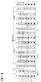
図11は、固定子コア232におけるスロット導体233aの配置を主に示す図であり、図7~10のスロット番号46~スロット番号13までを示したものである。なお、回転子の回転方向は図の左から右の方向である。
本実施形態では、2極分、つまり電気角360度にスロット237が12個配置されており、例えば、図11のスロット番号01からスロット番号12までは2極分に相当する。そのため、毎極スロット数Nは6、毎極毎相スロット数NSPPは2(=6/3)である。各スロット237には、固定子巻線238のスロット導体233aが6本ずつ挿通されている。
各スロット導体233aは矩形で示されている。矩形の中には、U相、V相、W相を示す符号U11~U26,V,Wと、口出し線がある側から反対側への方向を示すクロス印「×」、その逆の方向を示す黒丸印「●」がそれぞれ図示されている。また、スロット237の最も内周側(スロット開口側)にあるスロット導体233aをレイヤ1と呼び、外周側(スロット底側)にかけて順にレイヤ2、レイヤ3、レイヤ4、レイヤ5、レイヤ6と呼ぶことにする。また、符号01~12は図7~10に示したものと同様のスロット番号である。なお、U相のスロット導体233aのみ周回巻線を表す符号U11~U26で示し、V相およびW相のスロット導体233aに関しては、相を表す符号V,Wで示した。
図11において破線234で囲んだ12個のスロット導体233aは、全てU相のスロット導体233aからなるスロット導体群234である。具体例を示す。例えば、中央に示すスロット導体群234は、スロット番号06,07のレイヤ6からレイヤ5に配設された周回巻線U25,U26,U12,U11のスロット導体233aと、スロット番号05,06のレイヤ4からレイヤ1までに配設された周回巻線U23,U24,U14,U13,U21,U22,U16,U15のスロット導体233aとを有する。
一般に、毎極スロット数Nが6、毎極毎相スロット数NSPPが2、スロット237内のスロット導体233aのレイヤ数が6の場合には、図12に示すようにU相(V相、W相も同様)のスロット導体233aを配置する構成が採用される場合が多い。この場合、レイヤ2のスロット導体233aとレイヤ3のスロット導体233aを繋ぐジャンパー線の跨ぎ量Npjは7スロットピッチとなり、レイヤ4のスロット導体233aとレイヤ5のスロット導体233aを繋ぐジャンパー線の跨ぎ量Npjも7スロットピッチとなる。これにより、同一相の周回巻線が固定子コア232の周方向にずれることなく配設される。
一方、本実施形態の構成は、図13に示すように、図12に示したレイヤ5とレイヤ6の4本のスロット導体233aを回転子の回転方向(図の右方向)へ1スロットピッチ分ずらした構成となっている。このとき、レイヤ4のスロット導体233aとレイヤ5のスロット導体233aとを繋ぐジャンパー線J2の跨ぎ量Npjが6スロットピッチとなり、レイヤ2のスロット導体233aとレイヤ3のスロット導体233aとを繋ぐジャンパー線J1の跨ぎ量Npjは7スロットピッチとなる。
この場合、U相だけでなく、V相およびW相の対応する各スロット導体233aも同様に1スロットピッチ分ずらすことになるので、図11に示したように、U,V,W相に関して同一形状のスロット導体群234がそれぞれ形成される。すなわち、回転子の回転方向に対して、順に、U相でクロス印のスロット導体233aから成るスロット導体群、W相で黒丸印のスロット導体233aから成るスロット導体群、V相でクロス印のスロット導体233aから成るスロット導体群、U相で黒丸印のスロット導体233aから成るスロット導体群、W相でクロス印のスロット導体233aから成るスロット導体群、V相で黒丸印のスロット導体233aから成るスロット導体群が配置されることになる。
上述したように、レイヤ数を2×NL、nを1からNLまでの自然数と定義した場合、周回巻線はレイヤ2n-1とレイヤ2nとに挿通される。本実施形態では、図13に示すように、全体のレイヤ数は6なのでNL=3となる。周回巻線U15,U16,U21,U22は、n=1の場合のレイヤ1とレイヤ2とに挿通される。同様に、周回巻線U13,U14,U23,U24はn=2の場合のレイヤ3とレイヤ4とに挿通され、周回巻線U11,U12,U25,U26はn=NL=3の場合のレイヤ5とレイヤ6とに挿通される。
このレイヤ2n-1とレイヤ2nとに挿通される周回巻線のうち、径方向に異なる周回巻線を繋ぐ線がジャンパー線である。レイヤ数が6の場合にはジャンパー線が2つある。それらのジャンパー線には、Nを毎極スロット数と定義した場合、跨ぎ量Npjが(N+1)スロットピッチのものと、{(N+1)±1}スロットピッチのものとが含まれている。本実施形態では、図11に示すとおり毎極スロット数Nは6であって、7スロットピッチのジャンパー線J1は(N+1)スロットピッチのジャンパー線に対応し、6スロットピッチのジャンパー線J2は{(N+1)-1}スロットピッチのジャンパー線に対応している。
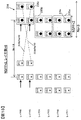
図13を用いて、本実施形態のスロット導体群234についてさらに説明する。スロット導体群234は、図13の破線で示すスロット導体小群235(235a、235b、235c)に分けることができる。スロット導体小群235は、固定子コア232の径方向に隣り合って互いに渡り導体233bに接続される内周側レイヤに挿通されるスロット導体233aと外周側レイヤに挿通されるスロット導体233aとで構成されている。ジャンパー線は、スロット導体小群235の内周側レイヤと、径方向に隣接するスロット導体小群235の外周側レイヤとの間に設けられている。例えば、スロット導体小群235cのレイヤ5とスロット導体小群235bのレイヤ4との間に、ジャンパー線が設けられている。
図13において、スロット導体小群235aとスロット導体小群235bとは周方向位置が一致している。この場合、図9に示すようにジャンパー線J1の跨ぎ量Npjは7スロットピッチ、すなわち(N+1)スロットピッチとなる。一方、スロット導体小群235cは隣接するスロット導体小群235bに対して回転方向(図示右方向)に1スロットピッチずれているので、ジャンパー線J2で接続されるスロット導体小群235cの内周側レイヤとスロット導体小群235bの外周側レイヤとが、1スロットピッチずれることになる。そのため、図9から分かるように、ジャンパー線J2の跨ぎ量Npjはジャンパー線J1の場合よりも1スロットピッチ少ないは6スロットピッチ、すなわち{(N+1)-1}スロットピッチとなる。
なお、スロット導体小群235bに対してスロット導体小群235cを回転方向と逆の方向(図示左方向)に1スロットピッチずらした場合には、ジャンパー線J2の跨ぎ量Npjはジャンパー線J1の場合よりも1スロットピッチ多い8スロットピッチ、すなわち{(N+1)+1}スロットピッチとなる。
上述したように、各相の固定子巻線は、固定子コア周方向に連続して並んだ所定スロット数Nsに挿通された複数のスロット導体233aで構成されるスロット導体群234と、複数のスロット導体233aのコイルエンド側を接続する渡り導体233bと、を備えている。一つのスロット導体群234に含まれる複数のスロット導体233aは、スロット導体233aが挿通されるスロットおよびレイヤが隣接するように配置されている。毎極毎相スロット数をNSPP、跨ぎ量Npjが{(N+1)±1}スロットピッチであるジャンパー線の1相あたりの数を2×NJと定義したとき、一つのスロット導体群234のスロット導体233aが挿通されるスロット237の数(以下では、所定スロット数Nsと称する)は、Ns=NSPP+NJのように設定されている。
本実施形態では、図7,8に示すU相巻線からも分かるように、{(N+1)-1}スロットピッチのジャンパー線J2がU1相巻線およびU2相巻線のそれぞれに1つあるので、NJは1(2×NJ=2)となる。また図13に示すようにNSPP=2でNs=3なので、Ns=NSPP+NJのように設定されていることが分かる。
ここで、図11等に示す本実施形態の回転電機の作用効果を、図12に示す比較例1、図20に示す比較例2と対比しながら説明する。
図12に示す比較例1では、スロット導体小群235a~235cは、周方向位置がずれておらず全て一致している。そのため、レイヤ2のスロット導体233aとレイヤ3のスロット導体233aを繋ぐジャンパー線の跨ぎ量Npjも、レイヤ4のスロット導体233aとレイヤ5のスロット導体233aを繋ぐジャンパー線の跨ぎ量Npjも(N+1)スロットピッチとなる。毎極スロット数NはN=6なので、(N+1)は7となる。
図20に示す比較例2では、スロット導体小群235bはスロット導体小群235aに対して図示左側に1スロットピッチずれており、さらに、スロット導体小群235cはスロット導体小群235bに対して図示左側に1スロットピッチずれている。しかしながら、ジャンパー線J1で繋がれるレイヤ2のスロット導体233aとレイヤ3のスロット導体233aとは同じスロットに挿通され、周方向位置が一致している。そのため、ジャンパー線J1の跨ぎ量Npjは(N+1)となる。ジャンパー線J2の場合も、ジャンパー線J1で繋がれるレイヤ4のスロット導体233aとレイヤ5のスロット導体233aとの周方向位置が同じなので、ジャンパー線J2の跨ぎ量Npjは(N+1)となる。
なお、図20に示す構成では、スロット導体小群235a~235cは、内周側レイヤに対して外周側レイヤが図示左方向に1スロットピッチだけずれている。そのため、所定スロット数NsはNs=5となっている。
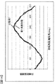
図14~図17には、本実施形態の回転電機の作用効果を、比較例1の作用効果と対比した場合を示す。図14は、本実施形態の回転電機の誘起電圧波形、および、比較例1の回転電機の誘起電圧波形を示す図である。図15は、図14のそれぞれの誘起電圧波形を高調波解析した結果を示したものである。
図14に示すように、本実施形態の回転電機の誘起電圧波形は、比較例1の回転電機の誘起電圧波形よりも正弦波に近いことが分かる。また、図15の高調波解析結果に示すように、本実施形態では、比較例1と比較して、特に、5次と7次の高調波成分を減らすことができることが分かった。
また、図16は、交流電流を通電した場合のトルク波形を、本実施形態の回転電機の場合と比較例1の回転電機の場合とについて示したものである。図17は、図16に示す各トルク波形を高調波解析した結果を示す。図17の高調波解析結果に示すように、特に、6次のトルクリプルを減らすことができることが分かった。これは、巻線配置を図7~11に示すように、ジャンパー線の跨ぎ量Npjとして(N+1)スロットピッチのものと{(N+1)±1}スロットピッチものとが含まれるようにスロット導体233aを配置したことにより、誘起電圧、すなわち鎖交磁束の5次と7次の成分が低減されたことを示す。
図18、図19は、本実施形態の発明の作用効果を、比較例2の作用効果と対比したものである。図18は、交流電流を通電した場合のトルク波形を、本実施形態の回転電機の場合と比較例2の回転電機の場合とについて示したものである。また、図19は、図18に示す各トルク波形を高調波解析した結果を示す。図18、図19に示すように、本実施形態では、比較例2と比較して、平均トルクが大きいことが分かった。
以上のように、本実施形態によれば、比較例1よりもトルクリプルが小さく低騒音で、比較例2よりも平均トルクが大きい回転電機を得ることができる。この意味で、本実施形態の回転電機は、高トルクかつ低騒音な回転電機を得ることができる。また、その回転電機を備えた車両では、高トルク化、かつ、低騒音化を図ることができる。
<変形例1>
図21は、上述した実施の形態の変形例1を示す図であり、スロット導体群234Bを示す。変形例1は、毎極スロット数N=6、NSPP=2であって、レイヤ数が8の場合である。レイヤ数が8となったことが、上述した実施の形態との相違点である。レイヤ数が8の場合には、スロット導体群234Bは4つのスロット導体小群235a~235dで構成される。
図21は、上述した実施の形態の変形例1を示す図であり、スロット導体群234Bを示す。変形例1は、毎極スロット数N=6、NSPP=2であって、レイヤ数が8の場合である。レイヤ数が8となったことが、上述した実施の形態との相違点である。レイヤ数が8の場合には、スロット導体群234Bは4つのスロット導体小群235a~235dで構成される。
変形例1では、スロット導体小群235b,235cはスロット導体小群235aに対して図示右側に1スロットピッチずれており、さらに、スロット導体小群235dはスロット導体小群235b,235cに対して図示右側に1スロットピッチずれている。そのため、レイヤ2のスロット導体233aとレイヤ3のスロット導体233aとを繋ぐジャンパー線、レイヤ6のスロット導体233aとレイヤ7のスロット導体233aとを繋ぐジャンパー線は、跨ぎ量Npjがそれぞれ6スロットピッチである。一方、レイヤ4のスロット導体233aとレイヤ5のスロット導体233aとを繋ぐジャンパー線の跨ぎ量Npjは、7スロットピッチである。
すなわち、U相(U1相およびU2相)の固定子巻線を構成する複数の周回巻線は、毎極スロット数N=6に対して、跨ぎ量Npjが(N+1)スロットピッチのジャンパー線と、{(N+1)-1}スロットピッチのジャンパー線とによって接続されている。このとき、{(N+1)-1}スロットピッチのジャンパー線の1相あたりの数(2×NJ)は4なので、NJ=2となり、Ns=NSPP+NJのように設定されていることがわかる。
変形例1においても、跨ぎ量Npjが(N+1)スロットピッチのジャンパー線と、{(N+1)-1}スロットピッチのジャンパー線とを含むように各相巻線が構成されているので、上述した実施の形態と同様に、比較例1よりもトルクリプルが小さく低騒音で、比較例2よりも平均トルクが大きいという効果を奏することができる。
<変形例2>
図22は、変形例2におけるスロット導体群234Cを示す図である。変形例2は、毎極スロット数N=6、NSPP=2、レイヤ数=8の設定である。変形例2では、スロット導体小群235c,235dはスロット導体小群235a,235bに対して図示右側に1スロットピッチずれている。そのため、レイヤ4のスロット導体233aとレイヤ5のスロット導体233aとを繋ぐジャンパー線の跨ぎ量Npjが6スロットピッチに設定され、レイヤ2のスロット導体233aとレイヤ3のスロット導体233aとを繋ぐジャンパー線、およびレイヤ6のスロット導体233aとレイヤ7のスロット導体233aとを繋ぐジャンパー線の跨ぎ量Npjがそれぞれ7スロットピッチに設定される。
図22は、変形例2におけるスロット導体群234Cを示す図である。変形例2は、毎極スロット数N=6、NSPP=2、レイヤ数=8の設定である。変形例2では、スロット導体小群235c,235dはスロット導体小群235a,235bに対して図示右側に1スロットピッチずれている。そのため、レイヤ4のスロット導体233aとレイヤ5のスロット導体233aとを繋ぐジャンパー線の跨ぎ量Npjが6スロットピッチに設定され、レイヤ2のスロット導体233aとレイヤ3のスロット導体233aとを繋ぐジャンパー線、およびレイヤ6のスロット導体233aとレイヤ7のスロット導体233aとを繋ぐジャンパー線の跨ぎ量Npjがそれぞれ7スロットピッチに設定される。
変形例2の場合も、毎極スロット数NがN=6なので、跨ぎ量Npjが(N+1)スロットピッチのジャンパー線と、{(N+1)-1}スロットピッチのジャンパー線とが含まれていることになる。また、跨ぎ量Npjが{(N+1)-1}スロットピッチのジャンパー線の1相あたりの数(2×NJ)は2となっているので、変形例2ではNJ=1である。そのため、所定スロット数Ns=3に対して、Ns=NSPP+NJが成り立っている。
このように、変形例2の場合も、跨ぎ量Npjが(N+1)スロットピッチのジャンパー線と、{(N+1)-1}スロットピッチのジャンパー線とを含むように各相巻線が構成されているので、上述した実施の形態と同様に、比較例1よりもトルクリプルが小さく低騒音で、比較例2よりも平均トルクが大きいという効果を奏することができる。なお、スロット導体小群235dをスロット導体小群235a,235bに対して図示右側に2スロットピッチずらし、ジャンパー線を3種類設けるように構成してよい。
<変形例3>
図23は、変形例3におけるスロット導体群234Dを示す図である。変形例3は、毎極スロット数N=9、NSPP=3、レイヤ数=6の設定となっており、毎極スロット数が9で、NSPPが3である点が上述した実施の形態と異なる。そのため、スロット導体小群235a,235b,235cには6つのスロット導体233aが含まれている。
図23は、変形例3におけるスロット導体群234Dを示す図である。変形例3は、毎極スロット数N=9、NSPP=3、レイヤ数=6の設定となっており、毎極スロット数が9で、NSPPが3である点が上述した実施の形態と異なる。そのため、スロット導体小群235a,235b,235cには6つのスロット導体233aが含まれている。
図23に示す変形例3では、スロット導体小群235a,235bの周方向は一致しており、スロット導体小群235cはスロット導体小群235a,235bに対して図示右側に1スロットピッチずれている。そのため、レイヤ4のスロット導体233aとレイヤ5のスロット導体233aとを繋ぐジャンパー線の跨ぎ量Npjは{(N+1)-1}スロットピッチとなり、レイヤ2のスロット導体233aとレイヤ3のスロット導体233aとを繋ぐジャンパー線の跨ぎ量Npjは(N+1)スロットピッチとなる。変形例3の場合には毎極スロット数がN=9なので、{(N+1)-1}は9となり、(N+1)は10となる。また、跨ぎ量Npjが{(N+1)-1}スロットピッチのジャンパー線の1相あたりの数(2×NJ)は2なので、NJ=1である。変形例3では所定スロット数NsはNs=4であるが、NSPP=3、NJ=1なので、Ns=NSPP+NJが成り立っている。
このように、変形例3の場合も、跨ぎ量Npjが(N+1)スロットピッチのジャンパー線と、{(N+1)-1}スロットピッチのジャンパー線とを含むように各相巻線が構成されているので、上述した実施の形態と同様に、比較例1よりもトルクリプルが小さく低騒音で、比較例2よりも平均トルクが大きいという効果を奏することができる。
上述したように、本実施形態の回転電機は、以下の構成を有し、以下の作用効果を奏する。
(1)回転電機200(回転電機202でも同様)における固定子巻線238は、巻線導体であるスロット導体233aが複数のスロット237の各々に6レイヤ以上挿通されるように、波巻で巻き回される周回巻線を複数有する。図9,10に示したように、固定子巻線238は、挿通されるレイヤが異なる周回巻線同士を接続するジャンパー線を複数有している。そして、複数のジャンパー線は、毎極スロット数をNとしたとき、スロット237を跨いで周回巻線同士を接続する際の跨ぎ量Npjが(N+1)スロットピッチであるジャンパー線J1と、{(N+1)±1}スロットピッチであるジャンパー線J2とを含む。
(1)回転電機200(回転電機202でも同様)における固定子巻線238は、巻線導体であるスロット導体233aが複数のスロット237の各々に6レイヤ以上挿通されるように、波巻で巻き回される周回巻線を複数有する。図9,10に示したように、固定子巻線238は、挿通されるレイヤが異なる周回巻線同士を接続するジャンパー線を複数有している。そして、複数のジャンパー線は、毎極スロット数をNとしたとき、スロット237を跨いで周回巻線同士を接続する際の跨ぎ量Npjが(N+1)スロットピッチであるジャンパー線J1と、{(N+1)±1}スロットピッチであるジャンパー線J2とを含む。
このようなジャンパー線J1,J2を含む場合には、図13に示すように、同一相の複数のスロット導体233aで構成されるスロット導体群234は、固定子コアの周方向にずれていないスロット導体小群235bと、1スロットピッチだけ周方向にずれたスロット導体小群235aとで構成される。このような構成とすることで、本実施形態の回転電機は、高トルクかつ低騒音な回転電機を得ることができる。また、その回転電機を備えた車両では、高トルク化、かつ、低騒音化を図ることができる。
(2)また、上記構成においては、所定スロット数をNs、毎極毎相スロット数をNSPP、跨ぎ量Npjが{(N+1)±1}スロットピッチのジャンパー線の1相あたりの数を2×NJとしたときに、Ns=NSPP+NJが成り立っている。すなわち、このような構成とすることで、回転電機の高トルク化、かつ、低騒音化を図ることができる。
<変形例4>
図24は、変形例4におけるスロット導体群234Eを示す図である。変形例4は、毎極スロット数N=6、NSPP=2、レイヤ数(2×NL)=6の設定である。レイヤ数が6の場合、NL=3である。図24に示すスロット導体群234Eでは、各スロット導体小群235a~235cの外側レイヤは、内側レイヤに対して回転方向(図示右方向)に1スロットピッチだけずれている。そのため、周回巻線において口出し線が引き出されているコイルエンド側(図示下側)における渡り導体233bの跨ぎ量Npが7スロットピッチ、反対側のコイルエンド側(図示上側)における渡り導体233bの跨ぎ量Npが5スロットピッチとなっている。変形例4は、このような変則スロットピッチの波巻で巻き回されていることが、上述した実施の形態および変形例1~3と相違している。
図24は、変形例4におけるスロット導体群234Eを示す図である。変形例4は、毎極スロット数N=6、NSPP=2、レイヤ数(2×NL)=6の設定である。レイヤ数が6の場合、NL=3である。図24に示すスロット導体群234Eでは、各スロット導体小群235a~235cの外側レイヤは、内側レイヤに対して回転方向(図示右方向)に1スロットピッチだけずれている。そのため、周回巻線において口出し線が引き出されているコイルエンド側(図示下側)における渡り導体233bの跨ぎ量Npが7スロットピッチ、反対側のコイルエンド側(図示上側)における渡り導体233bの跨ぎ量Npが5スロットピッチとなっている。変形例4は、このような変則スロットピッチの波巻で巻き回されていることが、上述した実施の形態および変形例1~3と相違している。
変形例4では、レイヤ4のスロット導体233aとレイヤ5のスロット導体233aとは、周方向位置が一致している。そのため、レイヤ4のスロット導体233aとレイヤ5のスロット導体233aとを繋ぐジャンパー線の跨ぎ量Npjは、毎極スロット数をNとしたとき(N+1)スロットピッチに設定される。一方、レイヤ3のスロット導体233aは、レイヤ2のスロット導体233aに対して図示左側に1スロットピッチずれている。そのため、レイヤ2のスロット導体233aとレイヤ3のスロット導体233aとを繋ぐジャンパー線の跨ぎ量Npjは{(N+1)+1}スロットピッチに設定される。
変形例4では毎極スロット数Nは6なので、(N+1)は7となり、{(N+1)+1}は8となる。また、跨ぎ量Npjが{(N+1)+1}スロットピッチであるジャンパー線の1相あたりの数(2×NJ)は2なので、NJ=1となる。
変形例4では、周回巻線が変則スロットピッチの波巻きで巻き回され、所定スロット数Nsは4となる。このような変則スロットピッチの場合には、上述した式「Ns=NSPP+NL」に代えて式「Ns=NSPP+NL-NJ」が成り立つ。ここで、NSPPは毎極毎相スロット数であって、2×NLはレイヤ数、2×NJは跨ぎ量Npjが{(N+1)+1}スロットピッチであるジャンパー線の1相あたりの数である。
変形例4のような構成においても、上述した実施形態の場合と同様に、比較例1よりもトルクリプルが小さく低騒音で、比較例2よりも平均トルクが大きいという効果を奏することができる。
<変形例5>
図25は、変形例5におけるスロット導体群234Fを示す図である。上述した変形例ではレイヤ数が6であったが、変形例5ではレイヤ数を8とした。すなわち、変形例5では、周回巻線が変則スロットピッチの波巻きで巻き回され、毎極スロット数N=6、NSPP=2、レイヤ数(2×NL)=8に設定されている。
図25は、変形例5におけるスロット導体群234Fを示す図である。上述した変形例ではレイヤ数が6であったが、変形例5ではレイヤ数を8とした。すなわち、変形例5では、周回巻線が変則スロットピッチの波巻きで巻き回され、毎極スロット数N=6、NSPP=2、レイヤ数(2×NL)=8に設定されている。
図25に示すように、レイヤ3のスロット導体233aは、レイヤ2のスロット導体233aに対して図示左側に1スロットピッチずれているので、毎極スロット数をNとしたとき、ジャンパー線の跨ぎ量Npjは{(N+1)+1}スロットピッチとなる。同様に、レイヤ6とレイヤ7とを繋ぐジャンパー線も、跨ぎ量Npjが{(N+1)+1}スロットピッチとなる。一方、レイヤ4のスロット導体233aとレイヤ5のスロット導体233aとは周方向位置が一致しているので、レイヤ4とレイヤ5とを繋ぐジャンパー線の跨ぎ量Npjは(N+1)となる。変形例5は毎極スロット数Nが6なので、{(N+1)+1}は8となり、(N+1)は7となる。
また、跨ぎ量Npjが{(N+1)+1}スロットピッチのジャンパー線の1相あたりの数(2×NJ)は4であり、NJ=2となる。図25に示すように固定子コア周方向に連続して並んだ所定スロット数Nsは4なので、変形例5の構成の場合もNs=NSPP+NL-NJが成り立っている。このような構成とすることで、比較例1よりもトルクリプルが小さく低騒音で、比較例2よりも平均トルクが大きいという効果を奏することができる。
<変形例6>
図26は、変形例6におけるスロット導体群234Gを示す図である。変形例6では、周回巻線が変則スロットピッチの波巻きで巻き回され、毎極スロット数N=9、NSPP=3、レイヤ数(2×NL)=6に設定されている。スロット導体小群235a~235cは、それぞれ6つのスロット導体233aを備えている。
図26は、変形例6におけるスロット導体群234Gを示す図である。変形例6では、周回巻線が変則スロットピッチの波巻きで巻き回され、毎極スロット数N=9、NSPP=3、レイヤ数(2×NL)=6に設定されている。スロット導体小群235a~235cは、それぞれ6つのスロット導体233aを備えている。
スロット導体小群235a,235bの周方向位置は一致しており、スロット導体小群235cはスロット導体小群235bに対して図示右側に1スロットピッチずれている。そのため、レイヤ3のスロット導体233aは、レイヤ2のスロット導体233aに対して図示左側に1スロットピッチずれている。レイヤ4のスロット導体233aとレイヤ5のスロット導体233aとは、周方向位置が一致している。
その結果、レイヤ2とレイヤ3を繋ぐジャンパー線の跨ぎ量Npjは{(N+1)+1}スロットピッチとなり、レイヤ4とレイヤ5とを繋ぐジャンパー線の跨ぎ量Npjは(N+1)スロットピッチとなる。変形例26では毎極スロット数Nが9なので、{(N+1)+1}は11となり、(N+1)は10となる。このように、ジャンパー線の跨ぎ量Npjは{(N+1)+1}スロットピッチと(N+1)スロットピッチとを含む。
また、跨ぎ量Npjが{(N+1)+1}スロットピッチのジャンパー線の1相あたりの数(2×NJ)は2であって、NJ=1となる。固定子コア周方向に連続して並んだ所定スロット数Nsは5なので、Ns=NSPP+NL-NJが成り立っている。変形例6の場合も、比較例1よりもトルクリプルが小さく低騒音で、比較例2よりも平均トルクが大きいという効果を奏することができる。
(3)上述した変形例4~6に記載の回転電機では、固定子巻線238は、同一相の複数のスロット導体233aで構成される一群のスロット導体群234を複数有し、スロット導体群234を構成する複数のスロット導体233aは、固定子コア周方向に連続して並んだ所定数Nsのスロット237内にスロットおよびレイヤが隣接するように挿通される。そして、毎極毎相スロット数をNSPP、レイヤ数を2×NL、スロットピッチ(N+1)±1のジャンパー線の1相あたりの数を2×NJと定義した場合に、所定数Nsは式「Ns=NSPP+NL-NJ」を満たす。
すなわち、Ns=NSPP+NL-NJの用に構成することで、回転電機の高トルク化、かつ、低騒音化を図ることができる。
上述した実施の形態および変形例では、NSPP=2または3、レイヤ数=6または8、通常の周回巻線または変則スロットピッチの波巻きで巻き回される周回巻線の例で説明したが、本発明はこれに限定されない。3以上のNSPPや8以上の偶数レイヤ、通常の周回巻線と変則スロットピッチの波巻きで巻き回される周回巻線の両方を有する巻線においても同様に適用することができ、同様の効果を奏する。
上記では、種々の実施の形態および変形例を説明したが、本発明はこれらの内容に限定されるものではない。本発明の技術的思想の範囲内で考えられるその他の態様も本発明の範囲内に含まれる。
100…車両、180…バッテリ、200,202…回転電機、230…固定子、232…固定子コア、233a…スロット導体、233b…渡り導体、234,234B~234G…スロット導体群、235,235a~235d…スロット導体小群、237…スロット、238…固定子巻線、250…回転子、600…電力変換装置、J1,J2…ジャンパー線、V11~V16,V21~V26,W11~W16,W21~W26,U11~U16,U21~U26…周回巻線
Claims (8)
1つのスロットにスロット導体が6個以上挿入される回転電機用の固定子において、
径方向において位置が異なる周回巻線を繋ぐジャンパー線のスロットピッチは少なくとも2種類以上の異なるスロットピッチでスロットを跨ぐ回転電機用の固定子。
径方向において位置が異なる周回巻線を繋ぐジャンパー線のスロットピッチは少なくとも2種類以上の異なるスロットピッチでスロットを跨ぐ回転電機用の固定子。
請求項1に記載の回転電機用の固定子であって、
前記ジャンパー線の前記異なるスロットピッチは、Nを毎極スロット数と定義した場合、NとN±1である回転電機用の固定子。
前記ジャンパー線の前記異なるスロットピッチは、Nを毎極スロット数と定義した場合、NとN±1である回転電機用の固定子。
請求項2に記載の回転電機用の固定子において、
同一相の複数の巻線導体で構成される一群のスロット導体群を複数有し、
前記スロット導体群を構成する複数の前記巻線導体は、固定子コア周方向に連続して並んだ所定数Nsのスロット内にスロットおよびレイヤが隣接するように挿通され、
毎極毎相スロット数をNSPP、前記{(N+1)±1}スロットピッチのジャンパー線の1相あたりの数を2×NJと定義した場合に、前記所定数Nsは式「Ns=NSPP+NJ」を満たすように設定されている回転電機。
同一相の複数の巻線導体で構成される一群のスロット導体群を複数有し、
前記スロット導体群を構成する複数の前記巻線導体は、固定子コア周方向に連続して並んだ所定数Nsのスロット内にスロットおよびレイヤが隣接するように挿通され、
毎極毎相スロット数をNSPP、前記{(N+1)±1}スロットピッチのジャンパー線の1相あたりの数を2×NJと定義した場合に、前記所定数Nsは式「Ns=NSPP+NJ」を満たすように設定されている回転電機。
請求項2に記載の回転電機用の固定子において、
同一相の複数の巻線導体で構成される一群のスロット導体群を複数有し、
前記スロット導体群を構成する複数の前記巻線導体は、固定子コア周方向に連続して並んだ所定数Nsのスロット内にスロットおよびレイヤが隣接するように挿通され、
毎極毎相スロット数をNSPP、レイヤ数を2×NL、前記スロットピッチ(N+1)±1のジャンパー線の1相あたりの数を2×NJと定義した場合に、前記所定数Nsは式「Ns=NSPP+NL-NJ」を満たすように設定されている回転電機用の固定子。
同一相の複数の巻線導体で構成される一群のスロット導体群を複数有し、
前記スロット導体群を構成する複数の前記巻線導体は、固定子コア周方向に連続して並んだ所定数Nsのスロット内にスロットおよびレイヤが隣接するように挿通され、
毎極毎相スロット数をNSPP、レイヤ数を2×NL、前記スロットピッチ(N+1)±1のジャンパー線の1相あたりの数を2×NJと定義した場合に、前記所定数Nsは式「Ns=NSPP+NL-NJ」を満たすように設定されている回転電機用の固定子。
請求項1乃至4のいずれか一項に記載の回転電機用の固定子において、
前記周回巻線は、複数のセグメント導体を接続することで構成される回転電機用の固定子。
前記周回巻線は、複数のセグメント導体を接続することで構成される回転電機用の固定子。
請求項1乃至4のいずれか一項に記載の回転電機用の固定子において、
前記周回巻線が平角線である回転電機用の固定子。
前記周回巻線が平角線である回転電機用の固定子。
請求項1乃至4のいずれか一項に記載の回転電機用の固定子において、
複数の前記周回巻線を有する3相Y結線を複数有し、
複数の前記3相Y結線のそれぞれは、各3相Y結線の同一相の巻線に誘起される電圧に位相差が無い回転電機用の固定子。
複数の前記周回巻線を有する3相Y結線を複数有し、
複数の前記3相Y結線のそれぞれは、各3相Y結線の同一相の巻線に誘起される電圧に位相差が無い回転電機用の固定子。
請求項1乃至4のいずれか一項に記載の回転電機用の固定子を有する回転電機と、
直流電力を供給するバッテリと、
前記バッテリの直流電力を交流電力に変換して前記回転電機に供給する変換装置と、を備え、
前記回転電機のトルクを駆動力として用いる車両。
直流電力を供給するバッテリと、
前記バッテリの直流電力を交流電力に変換して前記回転電機に供給する変換装置と、を備え、
前記回転電機のトルクを駆動力として用いる車両。
Priority Applications (3)
| Application Number | Priority Date | Filing Date | Title |
|---|---|---|---|
| US16/069,798 US10868448B2 (en) | 2016-01-12 | 2016-12-07 | Dynamo-electric machine and vehicle |
| JP2017561544A JP6513831B2 (ja) | 2016-01-12 | 2016-12-07 | 回転電機および車両 |
| CN201680077850.9A CN108432097B (zh) | 2016-01-12 | 2016-12-07 | 旋转电机用定子、旋转电机及车辆 |
Applications Claiming Priority (2)
| Application Number | Priority Date | Filing Date | Title |
|---|---|---|---|
| JP2016-003169 | 2016-01-12 | ||
| JP2016003169 | 2016-01-12 |
Publications (1)
| Publication Number | Publication Date |
|---|---|
| WO2017122463A1 true WO2017122463A1 (ja) | 2017-07-20 |
Family
ID=59311184
Family Applications (1)
| Application Number | Title | Priority Date | Filing Date |
|---|---|---|---|
| PCT/JP2016/086293 Ceased WO2017122463A1 (ja) | 2016-01-12 | 2016-12-07 | 回転電機および車両 |
Country Status (4)
| Country | Link |
|---|---|
| US (1) | US10868448B2 (ja) |
| JP (1) | JP6513831B2 (ja) |
| CN (1) | CN108432097B (ja) |
| WO (1) | WO2017122463A1 (ja) |
Cited By (1)
| Publication number | Priority date | Publication date | Assignee | Title |
|---|---|---|---|---|
| CN113258702A (zh) * | 2021-06-09 | 2021-08-13 | 厦门势拓御能科技有限公司 | 扁线电机、扁线电机定子及其绕线方法 |
Families Citing this family (14)
| Publication number | Priority date | Publication date | Assignee | Title |
|---|---|---|---|---|
| US10622875B2 (en) * | 2017-06-07 | 2020-04-14 | GM Global Technology Operations LLC | Interior permanent magnet electric machine |
| CN111463927B (zh) * | 2019-01-22 | 2021-08-17 | 上海汽车集团股份有限公司 | 定子组件及电机 |
| CN111725929B (zh) * | 2019-03-22 | 2023-02-28 | 上海汽车集团股份有限公司 | 用于电机的绕组结构及电机 |
| CN111327130A (zh) * | 2019-11-07 | 2020-06-23 | 东风电驱动系统有限公司 | 一种扁线电机定子和扁线电机 |
| DE102020111826A1 (de) * | 2020-04-30 | 2021-11-04 | Valeo Siemens Eautomotive Germany Gmbh | Stator für eine elektrische Maschine und elektrische Maschine |
| US11855498B2 (en) * | 2020-11-19 | 2023-12-26 | Atieva, Inc. | Patterns for balanced stator windings in electric motor |
| DE102021133278A1 (de) * | 2020-12-15 | 2022-06-15 | Borgwarner Inc. | Statorwicklung mit mehreren verschiebungen im phasenband |
| DE102020216149A1 (de) * | 2020-12-17 | 2022-06-23 | Valeo Siemens Eautomotive Germany Gmbh | Stator für eine elektrische Maschine und elektrische Maschine |
| DE102021208851A1 (de) | 2021-08-12 | 2023-02-16 | Valeo Eautomotive Germany Gmbh | Stator für eine elektrische Maschine, Verfahren zur Herstellung eines Stators, elektrische Maschine und Fahrzeug |
| CN114337034B (zh) * | 2021-09-23 | 2023-06-27 | 华为数字能源技术有限公司 | 一种电机及车辆 |
| EP4181356A1 (de) * | 2021-11-16 | 2023-05-17 | Valeo eAutomotive Germany GmbH | Stator für eine elektrische maschine, antriebseinrichtung für ein elektrisches fahrzeug und fahrzeug |
| DE102022133495A1 (de) | 2022-12-15 | 2024-06-20 | Valeo Eautomotive Germany Gmbh | Stator für eine elektrische Maschine |
| JPWO2025028539A1 (ja) | 2023-07-31 | 2025-02-06 | ||
| CN121586983A (zh) | 2023-07-31 | 2026-02-27 | 日本发条株式会社 | 旋转电机的定子 |
Citations (2)
| Publication number | Priority date | Publication date | Assignee | Title |
|---|---|---|---|---|
| JP2009011116A (ja) * | 2007-06-29 | 2009-01-15 | Hitachi Ltd | 渡り導体部がクランク形状の波巻きコイルを備えた回転電機、分布巻固定子並びにそれらの成形方法及び成形装置 |
| JP2014221003A (ja) * | 2014-07-24 | 2014-11-20 | 日立オートモティブシステムズ株式会社 | 回転電機、およびその回転電機を備えた車両 |
Family Cites Families (13)
| Publication number | Priority date | Publication date | Assignee | Title |
|---|---|---|---|---|
| EP0881744B1 (en) * | 1997-05-26 | 2005-07-20 | Denso Corporation | Alternator for vehicle |
| JP3155534B1 (ja) * | 2000-01-20 | 2001-04-09 | 三菱電機株式会社 | 交流発電機の固定子 |
| JP3748387B2 (ja) * | 2001-04-05 | 2006-02-22 | 株式会社日立製作所 | 永久磁石式回転電機及びそれを用いた発電システムと駆動システム |
| DE10362345B3 (de) * | 2002-05-15 | 2018-01-25 | Remy Inc. | Wicklungen aus rechtwinkligen Kupferhaarnadeln in mehreren Sätzen für elektrische Maschinen |
| US6979926B2 (en) * | 2002-06-12 | 2005-12-27 | Denso Corporation | Sequentially joined-segment coil for rotary electrical machine |
| JP3791471B2 (ja) * | 2002-07-12 | 2006-06-28 | 株式会社デンソー | セグメント順次接合ステータコイル型回転電機 |
| JP4940252B2 (ja) * | 2009-02-03 | 2012-05-30 | 株式会社日立製作所 | 回転電機の製造方法 |
| JP5587693B2 (ja) | 2010-07-20 | 2014-09-10 | 日立オートモティブシステムズ株式会社 | 回転電機、およびその回転電機を備えた車両 |
| JP5541585B2 (ja) * | 2010-12-28 | 2014-07-09 | 株式会社デンソー | 回転電機 |
| CN102364824B (zh) * | 2011-10-12 | 2013-05-22 | 泰豪科技股份有限公司 | 一种三相不等匝分数槽集中绕组 |
| US9166451B2 (en) * | 2011-12-02 | 2015-10-20 | Lg Electronics Inc. | Stator of electric machine, electromotor having the same, and electric vehicle having the electromotor |
| JP5948061B2 (ja) * | 2012-01-19 | 2016-07-06 | 日立オートモティブシステムズ株式会社 | 回転電機、およびその回転電機を備えた車両 |
| WO2014017361A1 (ja) * | 2012-07-26 | 2014-01-30 | 三菱電機株式会社 | 回転電機 |
-
2016
- 2016-12-07 CN CN201680077850.9A patent/CN108432097B/zh active Active
- 2016-12-07 JP JP2017561544A patent/JP6513831B2/ja active Active
- 2016-12-07 US US16/069,798 patent/US10868448B2/en active Active
- 2016-12-07 WO PCT/JP2016/086293 patent/WO2017122463A1/ja not_active Ceased
Patent Citations (2)
| Publication number | Priority date | Publication date | Assignee | Title |
|---|---|---|---|---|
| JP2009011116A (ja) * | 2007-06-29 | 2009-01-15 | Hitachi Ltd | 渡り導体部がクランク形状の波巻きコイルを備えた回転電機、分布巻固定子並びにそれらの成形方法及び成形装置 |
| JP2014221003A (ja) * | 2014-07-24 | 2014-11-20 | 日立オートモティブシステムズ株式会社 | 回転電機、およびその回転電機を備えた車両 |
Cited By (1)
| Publication number | Priority date | Publication date | Assignee | Title |
|---|---|---|---|---|
| CN113258702A (zh) * | 2021-06-09 | 2021-08-13 | 厦门势拓御能科技有限公司 | 扁线电机、扁线电机定子及其绕线方法 |
Also Published As
| Publication number | Publication date |
|---|---|
| JPWO2017122463A1 (ja) | 2018-06-14 |
| JP6513831B2 (ja) | 2019-05-15 |
| CN108432097B (zh) | 2020-03-27 |
| US10868448B2 (en) | 2020-12-15 |
| US20190027977A1 (en) | 2019-01-24 |
| CN108432097A (zh) | 2018-08-21 |
Similar Documents
| Publication | Publication Date | Title |
|---|---|---|
| JP6920504B2 (ja) | 回転電機の固定子、回転電機、および、その回転電機を備えた車両 | |
| JP6513831B2 (ja) | 回転電機および車両 | |
| JP5587693B2 (ja) | 回転電機、およびその回転電機を備えた車両 | |
| JP5792363B2 (ja) | 回転電機の固定子巻線、および回転電機の固定子 | |
| US11735968B2 (en) | Rotary electric machine and vehicle provided with the same | |
| US20140361646A1 (en) | Rotating Electric Machine and Vehicle Equipped with Rotating Electric Machine | |
| JP6227712B2 (ja) | 回転電機、およびその回転電機を備えた車両 | |
| JP6114786B2 (ja) | 回転電機の固定子巻線、回転電機の固定子、回転電機および車両 | |
| WO2022208929A1 (ja) | 回転電機の固定子、回転電機 | |
| JP2017189020A (ja) | 回転電機の固定子、及びこれを備えた回転電機 |
Legal Events
| Date | Code | Title | Description |
|---|---|---|---|
| 121 | Ep: the epo has been informed by wipo that ep was designated in this application |
Ref document number: 16885066 Country of ref document: EP Kind code of ref document: A1 |
|
| ENP | Entry into the national phase |
Ref document number: 2017561544 Country of ref document: JP Kind code of ref document: A |
|
| NENP | Non-entry into the national phase |
Ref country code: DE |
|
| 122 | Ep: pct application non-entry in european phase |
Ref document number: 16885066 Country of ref document: EP Kind code of ref document: A1 |