WO2017119205A1 - Metal composition, intermetallic compound member and bonded body - Google Patents
Metal composition, intermetallic compound member and bonded body Download PDFInfo
- Publication number
- WO2017119205A1 WO2017119205A1 PCT/JP2016/084699 JP2016084699W WO2017119205A1 WO 2017119205 A1 WO2017119205 A1 WO 2017119205A1 JP 2016084699 W JP2016084699 W JP 2016084699W WO 2017119205 A1 WO2017119205 A1 WO 2017119205A1
- Authority
- WO
- WIPO (PCT)
- Prior art keywords
- alloy
- intermetallic compound
- metal
- compound member
- crystal grain
- Prior art date
Links
- 229910000765 intermetallic Inorganic materials 0.000 title claims abstract description 159
- 229910052751 metal Inorganic materials 0.000 title claims description 145
- 239000002184 metal Substances 0.000 title claims description 145
- 239000000203 mixture Substances 0.000 title claims description 54
- 229910045601 alloy Inorganic materials 0.000 claims abstract description 181
- 239000000956 alloy Substances 0.000 claims abstract description 181
- 239000013078 crystal Substances 0.000 claims abstract description 51
- 238000002844 melting Methods 0.000 claims description 49
- 230000008018 melting Effects 0.000 claims description 49
- 238000005304 joining Methods 0.000 claims description 45
- 229910052723 transition metal Inorganic materials 0.000 claims description 17
- 230000004907 flux Effects 0.000 claims description 9
- 229910003336 CuNi Inorganic materials 0.000 claims description 8
- 229910052742 iron Inorganic materials 0.000 claims description 6
- 229910018565 CuAl Inorganic materials 0.000 claims description 3
- 229910052804 chromium Inorganic materials 0.000 claims description 3
- 238000006243 chemical reaction Methods 0.000 abstract description 18
- 239000004033 plastic Substances 0.000 abstract description 15
- 229910018227 Ni—Co—Sn Inorganic materials 0.000 abstract 2
- 229910017868 Cu—Ni—Co Inorganic materials 0.000 abstract 1
- 239000011888 foil Substances 0.000 description 53
- 238000012360 testing method Methods 0.000 description 33
- 238000010438 heat treatment Methods 0.000 description 31
- 239000002245 particle Substances 0.000 description 31
- 239000000463 material Substances 0.000 description 26
- 238000000034 method Methods 0.000 description 21
- 238000012669 compression test Methods 0.000 description 19
- 229910000753 refractory alloy Inorganic materials 0.000 description 13
- RSWGJHLUYNHPMX-UHFFFAOYSA-N Abietic-Saeure Natural products C12CCC(C(C)C)=CC2=CCC2C1(C)CCCC2(C)C(O)=O RSWGJHLUYNHPMX-UHFFFAOYSA-N 0.000 description 11
- KHPCPRHQVVSZAH-HUOMCSJISA-N Rosin Natural products O(C/C=C/c1ccccc1)[C@H]1[C@H](O)[C@@H](O)[C@@H](O)[C@@H](CO)O1 KHPCPRHQVVSZAH-HUOMCSJISA-N 0.000 description 11
- KHPCPRHQVVSZAH-UHFFFAOYSA-N trans-cinnamyl beta-D-glucopyranoside Natural products OC1C(O)C(O)C(CO)OC1OCC=CC1=CC=CC=C1 KHPCPRHQVVSZAH-UHFFFAOYSA-N 0.000 description 11
- 239000010949 copper Substances 0.000 description 9
- 238000004458 analytical method Methods 0.000 description 8
- 229910052759 nickel Inorganic materials 0.000 description 8
- 238000009826 distribution Methods 0.000 description 7
- 229910052802 copper Inorganic materials 0.000 description 6
- 230000003628 erosive effect Effects 0.000 description 6
- 239000012190 activator Substances 0.000 description 5
- 239000004020 conductor Substances 0.000 description 5
- 238000004519 manufacturing process Methods 0.000 description 5
- 239000002904 solvent Substances 0.000 description 5
- WNLRTRBMVRJNCN-UHFFFAOYSA-N adipic acid Chemical compound OC(=O)CCCCC(O)=O WNLRTRBMVRJNCN-UHFFFAOYSA-N 0.000 description 4
- -1 aromatics Chemical class 0.000 description 4
- 230000006835 compression Effects 0.000 description 4
- 238000007906 compression Methods 0.000 description 4
- BDAGIHXWWSANSR-UHFFFAOYSA-N methanoic acid Natural products OC=O BDAGIHXWWSANSR-UHFFFAOYSA-N 0.000 description 4
- 239000000843 powder Substances 0.000 description 4
- 230000007704 transition Effects 0.000 description 4
- QTBSBXVTEAMEQO-UHFFFAOYSA-N Acetic acid Chemical compound CC(O)=O QTBSBXVTEAMEQO-UHFFFAOYSA-N 0.000 description 3
- MUBZPKHOEPUJKR-UHFFFAOYSA-N Oxalic acid Chemical compound OC(=O)C(O)=O MUBZPKHOEPUJKR-UHFFFAOYSA-N 0.000 description 3
- 239000000654 additive Substances 0.000 description 3
- 238000010586 diagram Methods 0.000 description 3
- 238000009792 diffusion process Methods 0.000 description 3
- 230000035939 shock Effects 0.000 description 3
- 239000013008 thixotropic agent Substances 0.000 description 3
- OSWFIVFLDKOXQC-UHFFFAOYSA-N 4-(3-methoxyphenyl)aniline Chemical compound COC1=CC=CC(C=2C=CC(N)=CC=2)=C1 OSWFIVFLDKOXQC-UHFFFAOYSA-N 0.000 description 2
- OFOBLEOULBTSOW-UHFFFAOYSA-N Malonic acid Chemical compound OC(=O)CC(O)=O OFOBLEOULBTSOW-UHFFFAOYSA-N 0.000 description 2
- 229910007637 SnAg Inorganic materials 0.000 description 2
- 229910008433 SnCU Inorganic materials 0.000 description 2
- 229910007116 SnPb Inorganic materials 0.000 description 2
- 229910006913 SnSb Inorganic materials 0.000 description 2
- 229910005728 SnZn Inorganic materials 0.000 description 2
- 239000001361 adipic acid Substances 0.000 description 2
- 235000011037 adipic acid Nutrition 0.000 description 2
- WPYMKLBDIGXBTP-UHFFFAOYSA-N benzoic acid Chemical compound OC(=O)C1=CC=CC=C1 WPYMKLBDIGXBTP-UHFFFAOYSA-N 0.000 description 2
- 230000000052 comparative effect Effects 0.000 description 2
- 229910000777 cunife Inorganic materials 0.000 description 2
- POULHZVOKOAJMA-UHFFFAOYSA-N dodecanoic acid Chemical compound CCCCCCCCCCCC(O)=O POULHZVOKOAJMA-UHFFFAOYSA-N 0.000 description 2
- 238000001887 electron backscatter diffraction Methods 0.000 description 2
- 235000019253 formic acid Nutrition 0.000 description 2
- 230000004927 fusion Effects 0.000 description 2
- IPCSVZSSVZVIGE-UHFFFAOYSA-N hexadecanoic acid Chemical compound CCCCCCCCCCCCCCCC(O)=O IPCSVZSSVZVIGE-UHFFFAOYSA-N 0.000 description 2
- 239000007791 liquid phase Substances 0.000 description 2
- 229910052748 manganese Inorganic materials 0.000 description 2
- 238000005259 measurement Methods 0.000 description 2
- 238000000691 measurement method Methods 0.000 description 2
- 238000002156 mixing Methods 0.000 description 2
- BDJRBEYXGGNYIS-UHFFFAOYSA-N nonanedioic acid Chemical compound OC(=O)CCCCCCCC(O)=O BDJRBEYXGGNYIS-UHFFFAOYSA-N 0.000 description 2
- LYRFLYHAGKPMFH-UHFFFAOYSA-N octadecanamide Chemical compound CCCCCCCCCCCCCCCCCC(N)=O LYRFLYHAGKPMFH-UHFFFAOYSA-N 0.000 description 2
- XNGIFLGASWRNHJ-UHFFFAOYSA-N phthalic acid Chemical compound OC(=O)C1=CC=CC=C1C(O)=O XNGIFLGASWRNHJ-UHFFFAOYSA-N 0.000 description 2
- CXMXRPHRNRROMY-UHFFFAOYSA-N sebacic acid Chemical compound OC(=O)CCCCCCCCC(O)=O CXMXRPHRNRROMY-UHFFFAOYSA-N 0.000 description 2
- 229910052709 silver Inorganic materials 0.000 description 2
- 239000000126 substance Substances 0.000 description 2
- FMZUHGYZWYNSOA-VVBFYGJXSA-N (1r)-1-[(4r,4ar,8as)-2,6-diphenyl-4,4a,8,8a-tetrahydro-[1,3]dioxino[5,4-d][1,3]dioxin-4-yl]ethane-1,2-diol Chemical compound C([C@@H]1OC(O[C@@H]([C@@H]1O1)[C@H](O)CO)C=2C=CC=CC=2)OC1C1=CC=CC=C1 FMZUHGYZWYNSOA-VVBFYGJXSA-N 0.000 description 1
- HDUNAIVOFOKALD-RLCYQCIGSA-N (1s,2s)-1-[(4r)-2-(4-methylphenyl)-1,3-dioxolan-4-yl]-2-[(4s)-2-(4-methylphenyl)-1,3-dioxolan-4-yl]ethane-1,2-diol Chemical compound C1=CC(C)=CC=C1C1O[C@@H]([C@@H](O)[C@H](O)[C@H]2OC(OC2)C=2C=CC(C)=CC=2)CO1 HDUNAIVOFOKALD-RLCYQCIGSA-N 0.000 description 1
- DMRXISNUOWIOKV-UHFFFAOYSA-N 1-bromobutan-2-ol Chemical compound CCC(O)CBr DMRXISNUOWIOKV-UHFFFAOYSA-N 0.000 description 1
- RTBFRGCFXZNCOE-UHFFFAOYSA-N 1-methylsulfonylpiperidin-4-one Chemical compound CS(=O)(=O)N1CCC(=O)CC1 RTBFRGCFXZNCOE-UHFFFAOYSA-N 0.000 description 1
- 239000005711 Benzoic acid Substances 0.000 description 1
- RYGMFSIKBFXOCR-UHFFFAOYSA-N Copper Chemical compound [Cu] RYGMFSIKBFXOCR-UHFFFAOYSA-N 0.000 description 1
- 229910016507 CuCo Inorganic materials 0.000 description 1
- 229910016551 CuPt Inorganic materials 0.000 description 1
- 239000005639 Lauric acid Substances 0.000 description 1
- 235000021314 Palmitic acid Nutrition 0.000 description 1
- BQCADISMDOOEFD-UHFFFAOYSA-N Silver Chemical compound [Ag] BQCADISMDOOEFD-UHFFFAOYSA-N 0.000 description 1
- 235000021355 Stearic acid Nutrition 0.000 description 1
- 229930183415 Suberin Natural products 0.000 description 1
- KDYFGRWQOYBRFD-UHFFFAOYSA-N Succinic acid Natural products OC(=O)CCC(O)=O KDYFGRWQOYBRFD-UHFFFAOYSA-N 0.000 description 1
- 239000002253 acid Substances 0.000 description 1
- NIXOWILDQLNWCW-UHFFFAOYSA-N acrylic acid group Chemical group C(C=C)(=O)O NIXOWILDQLNWCW-UHFFFAOYSA-N 0.000 description 1
- 230000000996 additive effect Effects 0.000 description 1
- 150000001298 alcohols Chemical class 0.000 description 1
- 238000005275 alloying Methods 0.000 description 1
- 229910052782 aluminium Inorganic materials 0.000 description 1
- 150000001408 amides Chemical class 0.000 description 1
- 150000001412 amines Chemical class 0.000 description 1
- JFCQEDHGNNZCLN-UHFFFAOYSA-N anhydrous glutaric acid Natural products OC(=O)CCCC(O)=O JFCQEDHGNNZCLN-UHFFFAOYSA-N 0.000 description 1
- 235000013871 bee wax Nutrition 0.000 description 1
- 239000012166 beeswax Substances 0.000 description 1
- 235000010233 benzoic acid Nutrition 0.000 description 1
- AGEZXYOZHKGVCM-UHFFFAOYSA-N benzyl bromide Chemical class BrCC1=CC=CC=C1 AGEZXYOZHKGVCM-UHFFFAOYSA-N 0.000 description 1
- 229910052797 bismuth Inorganic materials 0.000 description 1
- KDYFGRWQOYBRFD-NUQCWPJISA-N butanedioic acid Chemical compound O[14C](=O)CC[14C](O)=O KDYFGRWQOYBRFD-NUQCWPJISA-N 0.000 description 1
- 238000004364 calculation method Methods 0.000 description 1
- 229910052799 carbon Inorganic materials 0.000 description 1
- 235000013869 carnauba wax Nutrition 0.000 description 1
- 239000004203 carnauba wax Substances 0.000 description 1
- 239000004359 castor oil Substances 0.000 description 1
- 235000019438 castor oil Nutrition 0.000 description 1
- 239000003985 ceramic capacitor Substances 0.000 description 1
- VNNRSPGTAMTISX-UHFFFAOYSA-N chromium nickel Chemical compound [Cr].[Ni] VNNRSPGTAMTISX-UHFFFAOYSA-N 0.000 description 1
- 238000013329 compounding Methods 0.000 description 1
- 150000004696 coordination complex Chemical class 0.000 description 1
- 230000006378 damage Effects 0.000 description 1
- 238000005034 decoration Methods 0.000 description 1
- 229940087101 dibenzylidene sorbitol Drugs 0.000 description 1
- 150000001991 dicarboxylic acids Chemical class 0.000 description 1
- 235000014113 dietary fatty acids Nutrition 0.000 description 1
- 150000002148 esters Chemical class 0.000 description 1
- 150000002170 ethers Chemical class 0.000 description 1
- 229930195729 fatty acid Natural products 0.000 description 1
- 239000000194 fatty acid Substances 0.000 description 1
- 229910052733 gallium Inorganic materials 0.000 description 1
- 229910052732 germanium Inorganic materials 0.000 description 1
- ZEMPKEQAKRGZGQ-XOQCFJPHSA-N glycerol triricinoleate Natural products CCCCCC[C@@H](O)CC=CCCCCCCCC(=O)OC[C@@H](COC(=O)CCCCCCCC=CC[C@@H](O)CCCCCC)OC(=O)CCCCCCCC=CC[C@H](O)CCCCCC ZEMPKEQAKRGZGQ-XOQCFJPHSA-N 0.000 description 1
- 229910052737 gold Inorganic materials 0.000 description 1
- 238000005324 grain boundary diffusion Methods 0.000 description 1
- 229930195733 hydrocarbon Natural products 0.000 description 1
- 150000002430 hydrocarbons Chemical class 0.000 description 1
- CUILPNURFADTPE-UHFFFAOYSA-N hypobromous acid Chemical class BrO CUILPNURFADTPE-UHFFFAOYSA-N 0.000 description 1
- 238000010191 image analysis Methods 0.000 description 1
- 238000003384 imaging method Methods 0.000 description 1
- 230000001771 impaired effect Effects 0.000 description 1
- 239000012535 impurity Substances 0.000 description 1
- 229910001026 inconel Inorganic materials 0.000 description 1
- 229910052738 indium Inorganic materials 0.000 description 1
- 230000006698 induction Effects 0.000 description 1
- 150000002576 ketones Chemical class 0.000 description 1
- 238000007561 laser diffraction method Methods 0.000 description 1
- 229910052745 lead Inorganic materials 0.000 description 1
- 239000000155 melt Substances 0.000 description 1
- 150000002736 metal compounds Chemical class 0.000 description 1
- 150000002739 metals Chemical class 0.000 description 1
- 229910052750 molybdenum Inorganic materials 0.000 description 1
- 150000002763 monocarboxylic acids Chemical class 0.000 description 1
- WQEPLUUGTLDZJY-UHFFFAOYSA-N n-Pentadecanoic acid Natural products CCCCCCCCCCCCCCC(O)=O WQEPLUUGTLDZJY-UHFFFAOYSA-N 0.000 description 1
- 229910001120 nichrome Inorganic materials 0.000 description 1
- QIQXTHQIDYTFRH-UHFFFAOYSA-N octadecanoic acid Chemical compound CCCCCCCCCCCCCCCCCC(O)=O QIQXTHQIDYTFRH-UHFFFAOYSA-N 0.000 description 1
- OQCDKBAXFALNLD-UHFFFAOYSA-N octadecanoic acid Natural products CCCCCCCC(C)CCCCCCCCC(O)=O OQCDKBAXFALNLD-UHFFFAOYSA-N 0.000 description 1
- 235000006408 oxalic acid Nutrition 0.000 description 1
- 229910052763 palladium Inorganic materials 0.000 description 1
- 229910052698 phosphorus Inorganic materials 0.000 description 1
- 229910052697 platinum Inorganic materials 0.000 description 1
- 229920000768 polyamine Polymers 0.000 description 1
- 238000006722 reduction reaction Methods 0.000 description 1
- 239000003870 refractory metal Substances 0.000 description 1
- 229910052706 scandium Inorganic materials 0.000 description 1
- SIXSYDAISGFNSX-UHFFFAOYSA-N scandium atom Chemical compound [Sc] SIXSYDAISGFNSX-UHFFFAOYSA-N 0.000 description 1
- 238000000790 scattering method Methods 0.000 description 1
- 238000007789 sealing Methods 0.000 description 1
- 239000004332 silver Substances 0.000 description 1
- 229940037312 stearamide Drugs 0.000 description 1
- 239000008117 stearic acid Substances 0.000 description 1
- 238000003860 storage Methods 0.000 description 1
- 239000000758 substrate Substances 0.000 description 1
- 238000004154 testing of material Methods 0.000 description 1
- 230000001052 transient effect Effects 0.000 description 1
- 229910052725 zinc Inorganic materials 0.000 description 1
Images


Classifications
-
- C—CHEMISTRY; METALLURGY
- C22—METALLURGY; FERROUS OR NON-FERROUS ALLOYS; TREATMENT OF ALLOYS OR NON-FERROUS METALS
- C22C—ALLOYS
- C22C9/00—Alloys based on copper
- C22C9/06—Alloys based on copper with nickel or cobalt as the next major constituent
-
- B—PERFORMING OPERATIONS; TRANSPORTING
- B23—MACHINE TOOLS; METAL-WORKING NOT OTHERWISE PROVIDED FOR
- B23K—SOLDERING OR UNSOLDERING; WELDING; CLADDING OR PLATING BY SOLDERING OR WELDING; CUTTING BY APPLYING HEAT LOCALLY, e.g. FLAME CUTTING; WORKING BY LASER BEAM
- B23K20/00—Non-electric welding by applying impact or other pressure, with or without the application of heat, e.g. cladding or plating
- B23K20/02—Non-electric welding by applying impact or other pressure, with or without the application of heat, e.g. cladding or plating by means of a press ; Diffusion bonding
- B23K20/023—Thermo-compression bonding
- B23K20/026—Thermo-compression bonding with diffusion of soldering material
-
- B—PERFORMING OPERATIONS; TRANSPORTING
- B23—MACHINE TOOLS; METAL-WORKING NOT OTHERWISE PROVIDED FOR
- B23K—SOLDERING OR UNSOLDERING; WELDING; CLADDING OR PLATING BY SOLDERING OR WELDING; CUTTING BY APPLYING HEAT LOCALLY, e.g. FLAME CUTTING; WORKING BY LASER BEAM
- B23K35/00—Rods, electrodes, materials, or media, for use in soldering, welding, or cutting
- B23K35/02—Rods, electrodes, materials, or media, for use in soldering, welding, or cutting characterised by mechanical features, e.g. shape
- B23K35/0222—Rods, electrodes, materials, or media, for use in soldering, welding, or cutting characterised by mechanical features, e.g. shape for use in soldering, brazing
- B23K35/0233—Sheets, foils
- B23K35/0238—Sheets, foils layered
-
- B—PERFORMING OPERATIONS; TRANSPORTING
- B23—MACHINE TOOLS; METAL-WORKING NOT OTHERWISE PROVIDED FOR
- B23K—SOLDERING OR UNSOLDERING; WELDING; CLADDING OR PLATING BY SOLDERING OR WELDING; CUTTING BY APPLYING HEAT LOCALLY, e.g. FLAME CUTTING; WORKING BY LASER BEAM
- B23K35/00—Rods, electrodes, materials, or media, for use in soldering, welding, or cutting
- B23K35/02—Rods, electrodes, materials, or media, for use in soldering, welding, or cutting characterised by mechanical features, e.g. shape
- B23K35/0222—Rods, electrodes, materials, or media, for use in soldering, welding, or cutting characterised by mechanical features, e.g. shape for use in soldering, brazing
- B23K35/0244—Powders, particles or spheres; Preforms made therefrom
- B23K35/025—Pastes, creams, slurries
-
- B—PERFORMING OPERATIONS; TRANSPORTING
- B23—MACHINE TOOLS; METAL-WORKING NOT OTHERWISE PROVIDED FOR
- B23K—SOLDERING OR UNSOLDERING; WELDING; CLADDING OR PLATING BY SOLDERING OR WELDING; CUTTING BY APPLYING HEAT LOCALLY, e.g. FLAME CUTTING; WORKING BY LASER BEAM
- B23K35/00—Rods, electrodes, materials, or media, for use in soldering, welding, or cutting
- B23K35/22—Rods, electrodes, materials, or media, for use in soldering, welding, or cutting characterised by the composition or nature of the material
- B23K35/24—Selection of soldering or welding materials proper
- B23K35/26—Selection of soldering or welding materials proper with the principal constituent melting at less than 400 degrees C
- B23K35/262—Sn as the principal constituent
-
- B—PERFORMING OPERATIONS; TRANSPORTING
- B23—MACHINE TOOLS; METAL-WORKING NOT OTHERWISE PROVIDED FOR
- B23K—SOLDERING OR UNSOLDERING; WELDING; CLADDING OR PLATING BY SOLDERING OR WELDING; CUTTING BY APPLYING HEAT LOCALLY, e.g. FLAME CUTTING; WORKING BY LASER BEAM
- B23K35/00—Rods, electrodes, materials, or media, for use in soldering, welding, or cutting
- B23K35/22—Rods, electrodes, materials, or media, for use in soldering, welding, or cutting characterised by the composition or nature of the material
- B23K35/24—Selection of soldering or welding materials proper
- B23K35/30—Selection of soldering or welding materials proper with the principal constituent melting at less than 1550 degrees C
- B23K35/302—Cu as the principal constituent
-
- B—PERFORMING OPERATIONS; TRANSPORTING
- B23—MACHINE TOOLS; METAL-WORKING NOT OTHERWISE PROVIDED FOR
- B23K—SOLDERING OR UNSOLDERING; WELDING; CLADDING OR PLATING BY SOLDERING OR WELDING; CUTTING BY APPLYING HEAT LOCALLY, e.g. FLAME CUTTING; WORKING BY LASER BEAM
- B23K35/00—Rods, electrodes, materials, or media, for use in soldering, welding, or cutting
- B23K35/22—Rods, electrodes, materials, or media, for use in soldering, welding, or cutting characterised by the composition or nature of the material
- B23K35/24—Selection of soldering or welding materials proper
- B23K35/30—Selection of soldering or welding materials proper with the principal constituent melting at less than 1550 degrees C
- B23K35/3033—Ni as the principal constituent
- B23K35/304—Ni as the principal constituent with Cr as the next major constituent
-
- H—ELECTRICITY
- H05—ELECTRIC TECHNIQUES NOT OTHERWISE PROVIDED FOR
- H05K—PRINTED CIRCUITS; CASINGS OR CONSTRUCTIONAL DETAILS OF ELECTRIC APPARATUS; MANUFACTURE OF ASSEMBLAGES OF ELECTRICAL COMPONENTS
- H05K3/00—Apparatus or processes for manufacturing printed circuits
- H05K3/30—Assembling printed circuits with electric components, e.g. with resistor
- H05K3/32—Assembling printed circuits with electric components, e.g. with resistor electrically connecting electric components or wires to printed circuits
- H05K3/34—Assembling printed circuits with electric components, e.g. with resistor electrically connecting electric components or wires to printed circuits by soldering
- H05K3/3457—Solder materials or compositions; Methods of application thereof
- H05K3/3463—Solder compositions in relation to features of the printed circuit board or the mounting process
-
- B—PERFORMING OPERATIONS; TRANSPORTING
- B23—MACHINE TOOLS; METAL-WORKING NOT OTHERWISE PROVIDED FOR
- B23K—SOLDERING OR UNSOLDERING; WELDING; CLADDING OR PLATING BY SOLDERING OR WELDING; CUTTING BY APPLYING HEAT LOCALLY, e.g. FLAME CUTTING; WORKING BY LASER BEAM
- B23K2101/00—Articles made by soldering, welding or cutting
- B23K2101/36—Electric or electronic devices
-
- H—ELECTRICITY
- H05—ELECTRIC TECHNIQUES NOT OTHERWISE PROVIDED FOR
- H05K—PRINTED CIRCUITS; CASINGS OR CONSTRUCTIONAL DETAILS OF ELECTRIC APPARATUS; MANUFACTURE OF ASSEMBLAGES OF ELECTRICAL COMPONENTS
- H05K1/00—Printed circuits
- H05K1/18—Printed circuits structurally associated with non-printed electric components
- H05K1/181—Printed circuits structurally associated with non-printed electric components associated with surface mounted components
-
- H—ELECTRICITY
- H05—ELECTRIC TECHNIQUES NOT OTHERWISE PROVIDED FOR
- H05K—PRINTED CIRCUITS; CASINGS OR CONSTRUCTIONAL DETAILS OF ELECTRIC APPARATUS; MANUFACTURE OF ASSEMBLAGES OF ELECTRICAL COMPONENTS
- H05K2201/00—Indexing scheme relating to printed circuits covered by H05K1/00
- H05K2201/10—Details of components or other objects attached to or integrated in a printed circuit board
- H05K2201/10007—Types of components
- H05K2201/10015—Non-printed capacitor
-
- H—ELECTRICITY
- H05—ELECTRIC TECHNIQUES NOT OTHERWISE PROVIDED FOR
- H05K—PRINTED CIRCUITS; CASINGS OR CONSTRUCTIONAL DETAILS OF ELECTRIC APPARATUS; MANUFACTURE OF ASSEMBLAGES OF ELECTRICAL COMPONENTS
- H05K2203/00—Indexing scheme relating to apparatus or processes for manufacturing printed circuits covered by H05K3/00
- H05K2203/04—Soldering or other types of metallurgic bonding
- H05K2203/0415—Small preforms other than balls, e.g. discs, cylinders or pillars
-
- H—ELECTRICITY
- H05—ELECTRIC TECHNIQUES NOT OTHERWISE PROVIDED FOR
- H05K—PRINTED CIRCUITS; CASINGS OR CONSTRUCTIONAL DETAILS OF ELECTRIC APPARATUS; MANUFACTURE OF ASSEMBLAGES OF ELECTRICAL COMPONENTS
- H05K3/00—Apparatus or processes for manufacturing printed circuits
- H05K3/30—Assembling printed circuits with electric components, e.g. with resistor
- H05K3/32—Assembling printed circuits with electric components, e.g. with resistor electrically connecting electric components or wires to printed circuits
- H05K3/34—Assembling printed circuits with electric components, e.g. with resistor electrically connecting electric components or wires to printed circuits by soldering
- H05K3/341—Surface mounted components
- H05K3/3431—Leadless components
Definitions
- the present invention relates to a metal composition containing a metal component, an intermetallic compound member produced from the metal composition, and a joined body including the intermetallic compound member.
- Patent Document 1 discloses a conductive material.
- the conductive material includes a metal component including Sn powder and CuNi alloy powder and a flux.
- the conductive material is provided between the pair of electrodes.
- the Sn powder and the CuNi alloy powder in the conductive material react by being heated to produce a CuNiSn alloy that is an intermetallic compound.
- the conductive material becomes an intermetallic compound member composed of an intermetallic compound.
- an intermetallic compound member joins a pair of electrodes.
- the intermetallic compound member forms a joined body together with a pair of electrodes.
- the heating temperature is not less than the melting point of Sn and not more than the melting point of the CuNi alloy, for example, 250 to 350 ° C.
- the CuNiSn alloy has a high melting point (for example, 400 ° C. or higher). Therefore, the intermetallic compound member is excellent in heat resistance.
- the conventional intermetallic compound member including the intermetallic compound member of Patent Document 1 generally does not easily cause crystal slip except for some special ones having a face-centered cubic lattice structure. Thereby, it is known that the conventional intermetallic compound member is difficult to be plastically deformed. Therefore, when the mechanical stress due to thermal shock is large, the intermetallic compound member of Patent Document 1 cannot absorb the mechanical stress due to the low plastic deformability described above, and may cause brittle fracture.
- An object of the present invention is to provide a metal composition, an intermetallic compound member, and a joined body that can generate an intermetallic compound member that has high plastic deformability at high temperatures and hardly causes brittle fracture.
- the metal composition of the present invention includes a first metal and a second alloy.
- the second alloy is an alloy in which a first transition metal element is added to a first alloy having a melting point higher than that of the first metal, and can generate an intermetallic compound with the first metal.
- the first metal is, for example, Sn or an Sn-based alloy.
- the first alloy is, for example, a CuAl alloy, a CuCr alloy, a CuNi alloy, or a CuMn alloy.
- the first transition metal element is, for example, any one of Co, Fe, and Cr.
- x is preferably in the range of 1 to 30, and y is preferably in the range of 0.5 to 20.
- the first metal and the second alloy react to generate an intermetallic compound.
- the metal composition of this structure produces
- the average crystal grain size of the intermetallic compound member produced with this configuration is smaller than the average crystal grain size of the conventional intermetallic compound member.
- the second alloy is an alloy in which the first transition metal element is added to the first alloy.
- the intermetallic compound member having this configuration has a high plastic deformability at a high temperature as compared with a conventional intermetallic compound member having a large crystal grain size. Therefore, the intermetallic compound member having this configuration can absorb the mechanical stress even when the mechanical stress due to thermal shock is large, and does not easily cause brittle fracture.
- the metal composition having this configuration can produce an intermetallic compound member that has high plastic deformability at high temperatures and hardly causes brittle fracture. Furthermore, this intermetallic compound member has high strength at room temperature.
- the metal composition of the present invention further contains a flux.
- the flux performs a reducing function of removing an oxide film on the surface of the first metal and the surface of the second alloy. Therefore, the metal composition having this configuration can promote the reaction between the first metal and the second alloy.
- the intermetallic compound member of the present invention is composed of an intermetallic compound composed of a first metal and a second alloy.
- the second alloy is an alloy in which a first transition metal element is added to a first alloy having a melting point higher than that of the first metal, and is an alloy that reacts with the first metal to generate an intermetallic compound.
- the average crystal grain size of the intermetallic compound is preferably 3 ⁇ m or less.
- the intermetallic compound member of the present invention is produced from the metal composition of the present invention. Therefore, the intermetallic compound member of the present invention has high plastic deformability at high temperatures and hardly causes brittle fracture. Furthermore, the intermetallic compound member of the present invention has high strength at room temperature.
- the joined body of the present invention includes the first joining object, the second joining object, and the intermetallic compound member of the present invention that joins the first joining object and the second joining object.
- the joined body of the present invention includes the intermetallic compound member of the present invention, it has high plastic deformability at high temperatures and hardly causes brittle fracture. Furthermore, the joined body of the present invention has high strength at room temperature.
- the intermetallic compound is continuously present from the first joining object to the second joining object in the intermetallic compound member.
- the metal composition of the present invention can produce an intermetallic compound member that has high plastic deformability at high temperatures and hardly causes brittle fracture. Further, the intermetallic compound member and the joined body of the present invention have high plastic deformability at high temperatures and hardly cause brittle fracture.
- FIG. 2 is a cross-sectional view taken along line SS shown in FIG. It is a flowchart which shows the joining method using the metal composition 10 shown in FIG. It is sectional drawing which shows the mode of the arrangement
- FIG. 10 is an enlarged cross-sectional view showing a polycrystalline intermetallic compound constituting an intermetallic compound member 800 according to a comparative example of the intermetallic compound member 100 shown in FIG. 9. It is a graph which shows distribution of the crystal grain size of each intermetallic compound. It is a figure which shows the relationship between the weight ratio of Ni and Co, and the crystal grain diameter of an intermetallic compound.
- FIG. 16 is an enlarged sectional view of a portion where cracks C1 to C3 are generated in the test piece 195 shown in FIG. It is a table
- surface which shows the relationship between Erosion Speed and an alloy composition.
- FIG. 1 is a front view of a metal composition 10 according to an embodiment of the present invention.
- 2 is a cross-sectional view taken along line SS shown in FIG.
- the dotted line in FIG. 1 has shown the fusion
- the metal composition 10 includes a metal foil 11 composed of a first metal, a refractory alloy paste 15 composed of a second alloy, and a metal foil 12 composed of a first metal.
- the second alloy is an alloy in which the first transition metal element is added to the first alloy, and is an alloy that reacts with the first first metal and the second first metal to generate an intermetallic compound.
- the intermetallic compound includes at least one of the metal foil 11 and the metal foil 12 and the second alloy.
- the material of the metal foil 11 is Sn or an Sn-based alloy.
- the material of the metal foil 12 is Sn or an Sn-based alloy.
- the Sn-based alloy include a SnAgCu alloy, a SnAg alloy, a SnCu alloy, a SnBi alloy, a SnSb alloy, a SnAu alloy, a SnPb alloy, and a SnZn alloy.
- the material of the metal foil 11 and the material of the metal foil 12 may be different materials or the same material.
- the material of the first alloy is, for example, a CuNi alloy, a CuMn alloy, a CuAl alloy, or a CuCr alloy.
- the material of the first alloy may be a CuTi alloy, CuCo alloy, CuPt alloy, NiCr alloy, NiV alloy, NiPd alloy, NiPt alloy, NiAu alloy, or the like.
- the material of the first transition metal element is a metal element from scandium Sc with atomic number 21 to copper Cu with atomic number 29.
- the material of the first transition metal element is preferably any element of Co, Fe, or Cr.
- the material of the second alloy is a material in which the first transition metal element is added to the first alloy, and examples thereof include a CuNiCo alloy, a CuMnCo alloy, a CuNiFe alloy, a CuMnFe alloy, a CuNiCr alloy, and a CuMnCr alloy.
- the second alloy is a Cu—xNi—yCo alloy
- the x is preferably in the range of 1 to 30
- the y is preferably in the range of 0.5 to 20.
- the material of the intermetallic compound is, for example, a CuNiCoSn alloy or a CuMnCoSn alloy. Specifically, the material of the intermetallic compound is, for example, ((Cu, Ni, Co) 6 Sn 5 ), ((Cu, Ni, Fe) 6 Sn 5 ), ((Cu, Ni, Cr) 6 Sn 5 ). Etc.
- the melting point of the first alloy is higher than the melting points of the metal foil 11 and the metal foil 12.
- the melting point of the second alloy is higher than the melting points of the metal foil 11 and the metal foil 12.
- the melting point of the intermetallic compound is higher than the melting points of the metal foil 11 and the metal foil 12.
- the metal foil 11 and the metal foil 12 are fused around the entire circumference of the refractory alloy paste 15 with the refractory alloy paste 15 sandwiched therebetween.
- the metal foil 11 and the metal foil 12 contain the high melting point alloy paste 15 as shown in FIG. That is, the metal foil 11 and the metal foil 12 seal the refractory alloy paste 15. Sealing corresponds to an example of storage.
- the high melting point alloy paste 15 is completely sealed.
- the high melting point alloy paste 15 is a paste in which a plurality of high melting point alloy particles 5 (metal components) composed of the second alloy are uniformly dispersed in the organic component 8. Therefore, the metal foil 11 and the metal foil 12 can further prevent the plurality of high melting point alloy particles 5 from being oxidized.
- the average particle diameter (D50) of the high melting point alloy particles 5 is preferably in the range of 0.1 ⁇ m to 30 ⁇ m.
- the average particle size (D50) means, for example, the particle size at an integrated value of 50% in the particle size distribution obtained by the laser diffraction / scattering method.
- the surface area of the refractory alloy particles 5 can be appropriately reduced. Thereby, it can suppress that an oxide is formed in the surface of the high melting point alloy particle 5, the wettability of the high melting point alloy particle 5 with respect to molten Sn improves, and the production
- the average particle diameter of the high melting point alloy particles 5 is 30 ⁇ m or less, the size of the gap between the high melting point alloy particles 5 is appropriately reduced. Thereby, it can utilize for the production
- the blending ratio of the metal component and the organic component within the above range, sufficient viscosity can be obtained, and the possibility that the metal component is peeled off from the organic component can be suppressed.
- the blending amount of the metal component is less than the above, the high melting point alloy particles 5 cannot be sufficiently reacted, and a large amount of unreacted high melting point alloy particles 5 remain in the intermetallic compound member 100 described later. There is a risk.
- the organic component 8 contains a flux, a solvent, a thixotropic agent, and the like.
- Flux contains rosin and activator.
- the flux fulfills a reducing function of removing oxide films on the surfaces of the metal foil 11, the metal foil 12, and the refractory alloy particles 5. Therefore, the flux can promote the reaction between the molten metal foil 11 and the second alloy or the metal foil 12 and the second alloy, which will be described in detail later.
- the rosin is, for example, natural rosin, hydrogenated rosin, disproportionated rosin, polymerized rosin, rosin derivatives such as unsaturated dibasic acid-modified rosin, acrylic acid-modified rosin, or a mixture thereof.
- rosin for example, polymerized rosin R-95 is used.
- Activators also promote the flux reduction reaction.
- Activators include, for example, monocarboxylic acids (eg, formic acid, acetic acid, lauric acid, palmitic acid, stearic acid, benzoic acid), dicarboxylic acids (eg, oxalic acid, malonic acid, succinic acid, glutaric acid, adipic acid, suberin) Acid, azelaic acid, sebacic acid, phthalic acid, etc.), bromoalcohols (eg, 1-bromo-2-butanol, etc.), organic amine hydrohalides, bromoalkanes, bromoalkenes, benzylbromides, polyamines And chlorinated activators.
- adipic acid is used as the activator.
- the solvent adjusts the viscosity of the high melting point alloy paste 15 of the metal composition 10.
- the solvent include alcohols, ketones, esters, ethers, aromatics, and hydrocarbons.
- HeDG hexyl diglycol
- the thixotropic agent is maintained so that the metal component and the organic component are not separated after the metal component and the organic component are uniformly mixed.
- thixotropic agents include hydrogenated castor oil, carnauba wax, amides, hydroxy fatty acids, dibenzylidene sorbitol, bis (p-methylbenzylidene) sorbitol, beeswax, stearamide, hydroxystearic acid ethylene bisamide, and the like.
- the high melting point alloy paste 15 includes, as additives, Ag, Au, Al, Bi, C, Co, Cu, Fe, Ga, Ge, In, Mn, Mo, Ni, P, Pb, Pd, Pt, Si, Sb, Zn, or the like may be included.
- the high melting point alloy paste 15 may contain not only these additives but also a metal complex, a metal compound, or the like as an additive.
- FIG. 3 is a flowchart showing a bonding method using the metal composition 10 shown in FIG.
- FIG. 4 is a cross-sectional view showing a state of an arrangement step performed by the joining method shown in FIG.
- FIG. 5 is a cross-sectional view illustrating a heating process performed by the bonding method illustrated in FIG. 3.
- 6 is a diagram showing a temperature profile of a heating process performed by the bonding method shown in FIG.
- FIG. 7 is a cross-sectional view showing a state of the intermetallic compound member 100 and the joined body 150 generated by the heating process performed by the joining method shown in FIG.
- FIG. 8 is an enlarged cross-sectional view showing a state of the intermetallic compound member 100 and the joined body 150 generated by the heating process performed by the joining method shown in FIG. 3.
- a metal composition 10 a first joining object 101, and a second joining object 102 are prepared.
- the CuNiCo alloy is an alloy in which the first transition metal element Co is added to the CuNi alloy.
- the CuNiCo alloy is a material that reacts with molten Sn to generate a CuNiCoSn alloy that is an intermetallic compound.
- the first joining object 101 and the second joining object 102 are, for example, electrode members formed on the surface of an element body such as a surface electrode of an electronic component such as a multilayer ceramic capacitor, and a print on which the electronic component is mounted. It is an electrode member provided on the surface of the wiring board.
- the material of the first joining object 101 and the second joining object 102 is, for example, Cu.
- the metal composition 10 is arranged between the first object 101 and the second object 102 (S11: arrangement process).
- the refractory alloy paste 15 is sealed with the metal foil 11 and the metal foil 12. Therefore, the high melting point alloy paste 15 does not contact the air outside the metal foil 11 and the metal foil 12.
- the first joining object 101, the second joining object 102, and the metal composition 10 are compressed from the thickness direction by the first joining object 101 and the second joining object 102.
- the metal composition 10 is heated (S12: heating step). In this heating step, for example, the metal composition 10 is heated according to a temperature profile shown in FIG.
- heating step to a temperature in the range below the melting point of the melting point T m above CuNiCo alloy of Sn, heating the metal composition 10.
- Melting point T m of a Sn is 231.9 ° C..
- the melting point of the CuNiCo alloy varies depending on the Ni content and is, for example, 1220 ° C. or higher.
- heating step for example, after preheating at 150 ° C. to 230 ° C., heating is performed at a heating temperature of 250 ° C. to 400 ° C. for 2 minutes to 10 minutes. The peak temperature is allowed to reach 400 ° C.
- the reflow apparatus stops heating. Accordingly, the temperature of the intermetallic compounds member 100 becomes less than the melting point T m of a Sn, the reaction between Sn and the refractory alloy particles 5 were melted completed. After t 2 has elapsed, the intermetallic compounds member 100 continue to cool to room temperature.
- the metal composition 10 becomes an intermetallic compound member 100 composed of an intermetallic compound as shown in FIGS.
- the intermetallic compound member 100 joins the first joining object 101 and the second joining object 102.
- the intermetallic compound member 100 constitutes a joined body 150 together with the first joining object 101 and the second joining object 102.
- the intermetallic compound member 100 has a dense structure with almost no fine voids.
- the intermetallic compound CuNiCoSn alloy
- the intermetallic compound member 100 can join the first joining object 101 and the second joining object 102 at a low temperature and has high heat resistance.
- the intermetallic compound CuNiCoSn alloy
- the electronic component having the intermetallic compound member 100 therein is further heated by reflow or other devices, components, substrates, etc. Even when mounted on, the structure of the intermetallic compound member 100 is not impaired. That is, the intermetallic compound member 100 can maintain the bonding force.
- an intermetallic compound member 100 composed of an intermetallic compound (CuNiCoSn alloy) and a conventional intermetallic compound member 800 composed of an intermetallic compound (CuNiSn alloy) will be compared.
- the conventional intermetallic compound member 800 is different from the intermetallic compound member 100 in that the first transition metal element Co is not added.
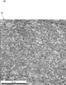
- FIG. 9 is an enlarged cross-sectional view showing a polycrystalline intermetallic compound constituting the intermetallic compound member 100 shown in FIG.
- FIG. 10 is an enlarged cross-sectional view showing a polycrystalline intermetallic compound constituting an intermetallic compound member 800 according to a comparative example of the intermetallic compound member 100 shown in FIG.
- FIG. 9 shows an image of a polycrystalline intermetallic compound generated by the reaction between the first metal Sn and the second alloy, Cu-10Ni-3Co alloy.
- FIG. 10 shows an image of a polycrystalline intermetallic compound produced by the reaction between the first metal Sn and the Cu-10Ni alloy as the first alloy.
- FIGS. 9 and 10 show images analyzed by OIM (Orientation Imaging Microscope) manufactured by TSL Solutions.
- the OIM is a device that analyzes an image measured by an EBSD (Electron Back Scatter Diffraction Patterns) measuring device with dedicated software.
- EBSD Electro Back Scatter Diffraction Patterns
- the OIM analyzes that the orientation difference between adjacent measurement points belongs to a different crystal grain if it is larger than a preset angle (5 ° in the present embodiment), and the preset angle (the present embodiment). If it is 5 ° or less, it is analyzed that they belong to the same crystal grain.
- OIM measurement and analysis revealed that the average crystal grain size of the intermetallic compound member 100 is smaller than the average crystal grain size of the conventional intermetallic compound member 800 as shown in FIGS.
- the reason is considered that the second alloy is an alloy in which the first transition metal element Co is added to the first alloy.
- FIG. 11 is a graph showing the crystal grain size distribution of each intermetallic compound.
- the horizontal axis of FIG. 11 is the crystal grain size
- the vertical axis of FIG. 11 is the ratio of the total area of crystal grains having the crystal grain size to the total area of the analysis section (cross-sectional area ratio) in the analysis section. ).
- the graph shown in FIG. 11 is the result of analysis by the aforementioned OIM.
- the solid line shown in FIG. 11 indicates the distribution of the crystal grain size of the intermetallic compound produced by the reaction between the first metal Sn and the Cu-3Ni alloy that is the first alloy.
- the dotted line shown in FIG. 11 shows the distribution of the crystal grain size of the intermetallic compound produced by the reaction between the first metal Sn and the Cu-5Ni alloy that is the first alloy.
- the alternate long and short dash line shown in FIG. 11 indicates the distribution of crystal grain size of the intermetallic compound produced by the reaction between the first metal Sn and the Cu-10Ni-5Co alloy as the second alloy.
- the alternate long and two short dashes line shown in FIG. 11 indicates the distribution of the crystal grain size of the intermetallic compound produced by the reaction between the first metal Sn and the Cu-10Ni alloy that is the first alloy.
- FIG. 12 is a graph showing the relationship between the weight ratio of Ni and Co and the average crystal grain size of the intermetallic compound.
- the average crystal grain size shown in FIG. 12 is obtained by the Area Fraction method based on the data analyzed by the aforementioned OIM. Specifically, in the analysis cross section of the OIM analysis, the average crystal area is obtained by summing each value obtained by multiplying the area and the cross-sectional area ratio for each crystal grain, and further, 4 times the average crystal area is calculated as the circumference ratio. The square root of the value divided by is the average grain size.
- the average crystal grain size of the intermetallic compound to which the first transition metal element Co is added is the average of the intermetallic compound to which the first transition metal element Co is not added, as shown in FIGS. It became clear that it was smaller than the crystal grain size.
- the average crystal grain size of the intermetallic compound to which the first transition metal element Co was added was found to be 3 ⁇ m or less as shown in FIG.
- FIG. 13 is a diagram illustrating a measurement method of a compression test performed on the intermetallic compound member 100 illustrated in FIG. 9 and the intermetallic compound member 800 illustrated in FIG. 10.
- the arrows in FIG. 13 indicate the compression direction.
- the compression test was measured using an Instron material testing machine (Instron 5982) and Inconel compression jigs 501 and 502.
- Instron material testing machine Instron 5982
- Each of the test pieces 191 and 193 is a prism having a width of 2 mm, a length of 2 mm, and a thickness of 4 mm.
- the test pieces 191 and 193 were compressed by the compression jigs 501 and 502 at a strain rate of 2.1 ⁇ 10 ⁇ 4 S ⁇ 1 and the stress was measured to obtain a stress-strain curve.
- FIG. 14 is a diagram showing a stress-strain curve showing a result of a compression test performed at normal temperature, 200 ° C., and 300 ° C. on the two test pieces 191 and 193 shown in FIG.
- the solid line in FIG. 14 shows the result of the test piece 191.
- the dotted line in FIG. 14 shows the result of the test piece 193.
- the x mark in the graph means the end of the test due to the destruction of the test piece.
- the test piece 193 having an average crystal grain size of 10.5 ⁇ m has a remarkable peak
- the test piece 191 having an average crystal grain size of 2.2 ⁇ m It became clear that the graph had no peak.
- the peak of the graph is considered to indicate that the crack that is the starting point of brittle fracture has occurred in the compression test.
- the test piece 193 having an average crystal grain size of 10.5 ⁇ m has undergone brittle fracture, and the test piece 191 having an average crystal grain size of 2.2 ⁇ m has not been brittle. It became clear.
- the graph has a remarkable peak in both the test piece 193 having an average crystal grain size of 10.5 ⁇ m and the test piece 191 having an average crystal grain size of 2.2 ⁇ m. became.
- the test piece 191 having an average crystal grain size of 2.2 ⁇ m has a peak at a position where the strain amount is larger than that of the test piece 193 having an average crystal grain size of 10.5 ⁇ m, that is, It was found that brittle fracture occurred and it was strong against strain.
- the test piece 191 having an average crystal grain size of 2.2 ⁇ m is broken at a position where the strain amount is larger than that of the test piece 193 having an average crystal grain size of 10.5 ⁇ m. It was revealed that it is strong against compressive stress.
- the intermetallic compound member 100 has a higher plastic deformability at a higher temperature than the conventional intermetallic compound member 800 having a large crystal grain size. Therefore, the intermetallic compound member 100 can absorb the mechanical stress even when the mechanical stress due to the thermal shock is large, and does not easily cause brittle fracture.
- the intermetallic compound member 100 has a high plastic deformability at high temperatures and hardly causes brittle fracture. Furthermore, the intermetallic compound member 100 has higher compressive strength at room temperature than the conventional intermetallic compound member 800 having a large crystal grain size.
- the intermetallic compound is continuously present in the intermetallic compound member 100 from the first joining object 101 to the second joining object 102. That is, an intermetallic compound having a high plastic deformability at a high temperature directly connects the first object 101 and the second object 102.
- the joined body 150 can sufficiently exhibit the high plastic deformability of the intermetallic compound.
- the fact that intermetallic compounds are continuously present means that there are few voids in the intermetallic compound member 100 and that the strength of the intermetallic compound member 100 itself is improved.
- the bonded body 150 has a high plastic deformability at high temperatures and hardly causes brittle fracture. Furthermore, the joined body 150 has high strength at room temperature.
- FIG. 15 is an enlarged cross-sectional view showing a state of a polycrystal constituting the test piece 195 after the compression test shown in FIG. 13 is performed.
- FIG. 16 is an enlarged cross-sectional view of a portion where cracks C1 to C3 have occurred in the test piece 195 shown in FIG.
- a test piece 195 in which an intermetallic compound having a large crystal grain size and an intermetallic compound having a small crystal grain size were mixed was used.
- FIG. 15 is an image taken by a backscattered electron detector.
- the average crystal grain size of the portion where the cracks C1 to C3 are generated in the test piece 195 is 3.06 ⁇ m as a result of analysis by the aforementioned OIM based on the Area Fraction method. It became. That is, it has been clarified that no crack which is the starting point of brittle fracture has occurred in the test piece 195 where the average crystal grain size is 3.0 ⁇ m or less.
- the average crystal grain size of the intermetallic compound is preferably 3.0 ⁇ m or less.
- FIG. 17 is a table showing the relationship between Erosion Speed and the alloy composition. Erosion Speed was measured when an alloy having the following composition was reacted with molten Sn under the following conditions.
- FIG. 1 is a sample No. 1 when Sn and CuNi alloy were reacted.
- Samples Nos. 2 to 5 show sample Nos.
- Sn and CuNiCo alloy were reacted.
- 6 shows a case where Sn and a CuNiFe alloy are reacted.
- the columns of Ni amount, Co amount, and Fe amount in FIG. 17 indicate the weight percentages of Ni, Co, and Fe contained in each sample.
- Erosion Speed is obtained by quantifying generated intermetallic compounds by image analysis, assuming that all are (Cu, M) 6Sn5, and Cu consumed per unit time for the generation of intermetallic compounds. This is a reverse calculation of the thickness of the alloy plate.
- the crystal grain size of the intermetallic compound produced by the reaction between the first metal and the second alloy is smaller than when the first transition element is not added. Become. As a result, it is considered that the grain boundary diffusion path of the first metal in the intermetallic compound is increased, the diffusion rate is improved, and the production rate of the intermetallic compound is increased.
- the material of the metal foil 11 and the metal foil 12 is Sn simple substance in the joining method of this embodiment, it is not restricted to this.
- the material of the metal foil 11 and the metal foil 12 may be a Sn-based alloy.
- the material of the metal foil 11 and the material of the metal foil 12 may be different. Examples of the Sn-based alloy include a SnAgCu alloy, a SnAg alloy, a SnCu alloy, a SnBi alloy, a SnSb alloy, a SnAu alloy, a SnPb alloy, and a SnZn alloy.
- the metal foil 11 and the metal foil 12 are fused around the entire circumference of the refractory alloy paste 15 with the refractory alloy paste 15 sandwiched therebetween. It is not limited to.
- the metal foil 11 and the metal foil 12 may be partly fused or may not be fused.
- the metal foil 12 may not be provided.
- the metal foil 11 and the metal foil 12 correspond to the first metal and the refractory alloy paste 15 corresponds to the second alloy, but it is not limited thereto.
- the first metal may not be in the form of foil, but may be in the form of particles or paste
- the second alloy may be in the form of particles or foil instead of in the form of paste. May be appropriately combined.
- the material of the high melting point alloy particles 5 is a CuNiCo alloy, but is not limited thereto.
- the material of the high melting point alloy particles 5 may be CuMnCo alloy particles, for example.
- the metals and alloys described in the present specification do not indicate a strict composition, and are clearly specified so as not to inhibit the reaction between the first metal and the second refractory metal, for example, at a ratio of 1% by weight or less. Elements that are not contained may be included as impurities.
- an intermetallic compound is generated by a reaction between molten Sn and CuMnCo alloy particles.
- This intermetallic compound is, for example, (Cu, Mn, Co) 6 Sn 5 .
- the heating step heats the metal composition 10 with hot air, but is not limited thereto.
- the heating step may be performed, for example, far infrared heating, high frequency induction heating, hot plate, or the like on the metal composition 10.
- the heating step heats the metal composition 10 in the air with hot air, but is not limited thereto.
- the heating step may be performed by heating the metal composition 10 with hot air in, for example, N 2 , H 2 , formic acid, or vacuum.
- the heating step pressurizes the metal composition 10 during heating, but is not limited thereto. In the implementation, the heating step may not pressurize the metal composition 10 during the heating.
- the metal composition 10 is used as a bonding material, but the use of the metal composition 10 is not limited to this.
- an intermetallic compound produced by the metal composition 10 may be used as a superplastic material for a vibration damper.
- intermetallic compounds are generally brittle, intermetallic compounds produced by the metal composition 10 have high plastic deformability and can be processed. Therefore, the intermetallic compound produced
- the intermetallic compound is a substance that can be processed and has a silver metallic texture, it may be used for, for example, modeling of arts and toys and decoration.
- intermetallic compound member 101 first 1 to-be-joined object 102 ... 2nd to-be-joined object 150 ... joined body 191, 193 ... test piece 195 ... test piece 501, 502 ... compression jig 800 ... intermetallic compound member
Abstract
A Cu-Ni-Co-Sn alloy which is an intermetallic compound obtained by a reaction between molten Sn and a Cu-Ni-Co alloy is produced. An intermetallic compound member (100) which is configured from the Cu-Ni-Co-Sn alloy is then produced. This intermetallic compound member (100) constitutes a bonded body (150) together with a first bonding object (101) and a second bonding object (102). The average crystal grain size of the intermetallic compound member (100) to which Co is added is smaller than the average crystal grain size of a conventional intermetallic compound member (800) to which Co is not added. Consequently, the intermetallic compound member (100) has a higher plastic deformability than the conventional intermetallic compound member (800) at high temperatures. This intermetallic compound member (100) is therefore not susceptible to brittle fracture.
Description
本発明は、金属成分を含む金属組成物、この金属組成物から生成される金属間化合物部材、及びこの金属間化合物部材を備える接合体に関するものである。
The present invention relates to a metal composition containing a metal component, an intermetallic compound member produced from the metal composition, and a joined body including the intermetallic compound member.
従来、例えば第1接合対象物と第2接合対象物とを接合するために、金属組成物が用いられている。このような金属組成物として例えば特許文献1は、導電性材料を開示している。
Conventionally, for example, a metal composition is used to join a first joining object and a second joining object. As such a metal composition, for example, Patent Document 1 discloses a conductive material.
導電性材料は、Sn粉末とCuNi合金粉末を含む金属成分とフラックスとを含んでいる。導電性材料は、一対の電極の間に設けられる。そして、導電性材料中のSn粉末とCuNi合金粉末とは、加熱されることによって反応し、金属間化合物であるCuNiSn合金を生成する。この結果、導電性材料は、金属間化合物で構成された金属間化合物部材となる。これにより、金属間化合物部材は、一対の電極を接合する。金属間化合物部材は、一対の電極とともに接合体を構成する。
The conductive material includes a metal component including Sn powder and CuNi alloy powder and a flux. The conductive material is provided between the pair of electrodes. The Sn powder and the CuNi alloy powder in the conductive material react by being heated to produce a CuNiSn alloy that is an intermetallic compound. As a result, the conductive material becomes an intermetallic compound member composed of an intermetallic compound. Thereby, an intermetallic compound member joins a pair of electrodes. The intermetallic compound member forms a joined body together with a pair of electrodes.
ここで、加熱の温度は、Snの融点以上、CuNi合金の融点以下であり、例えば250~350℃である。CuNiSn合金は、高い融点(例えば400℃以上)を有する。そのため、金属間化合物部材は、耐熱性に優れる。
Here, the heating temperature is not less than the melting point of Sn and not more than the melting point of the CuNi alloy, for example, 250 to 350 ° C. The CuNiSn alloy has a high melting point (for example, 400 ° C. or higher). Therefore, the intermetallic compound member is excellent in heat resistance.
しかしながら、特許文献1の金属間化合物部材を含む従来の金属間化合物部材は一般的に、面心立方格子構造を持つ一部の特殊なものを除いて結晶すべりを起こし難い。これにより、従来の金属間化合物部材は塑性変形し難いことが知られている。そのため、特許文献1の金属間化合物部材は、熱衝撃による機械的応力が大きい場合、前述の塑性変形能が低い性質から機械的応力を吸収することができず、脆性破壊を起こすことがある。
However, the conventional intermetallic compound member including the intermetallic compound member of Patent Document 1 generally does not easily cause crystal slip except for some special ones having a face-centered cubic lattice structure. Thereby, it is known that the conventional intermetallic compound member is difficult to be plastically deformed. Therefore, when the mechanical stress due to thermal shock is large, the intermetallic compound member of Patent Document 1 cannot absorb the mechanical stress due to the low plastic deformability described above, and may cause brittle fracture.
本発明の目的は、高温において高い塑性変形能を有し、脆性破壊を起こし難い金属間化合物部材を生成できる金属組成物、金属間化合物部材、及び接合体を提供することにある。
An object of the present invention is to provide a metal composition, an intermetallic compound member, and a joined body that can generate an intermetallic compound member that has high plastic deformability at high temperatures and hardly causes brittle fracture.
本発明の金属組成物は、第1金属と第2合金とを含む。第2合金は、第1金属より融点の高い第1合金に第1遷移金属元素が添加された合金であって、第1金属と金属間化合物を生成しうる合金である。
The metal composition of the present invention includes a first metal and a second alloy. The second alloy is an alloy in which a first transition metal element is added to a first alloy having a melting point higher than that of the first metal, and can generate an intermetallic compound with the first metal.
ここで、第1金属は例えば、Sn又はSn系合金である。第1合金は例えば、CuAl合金、CuCr合金、CuNi合金又はCuMn合金である。第1遷移金属元素は例えば、Co、Fe、及びCrのいずれか1つである。なお、第2合金がCu-xNi-yCo合金である場合、xは、1以上30以下の範囲内であり、yは、0.5以上20以下の範囲内であることが好ましい。
Here, the first metal is, for example, Sn or an Sn-based alloy. The first alloy is, for example, a CuAl alloy, a CuCr alloy, a CuNi alloy, or a CuMn alloy. The first transition metal element is, for example, any one of Co, Fe, and Cr. When the second alloy is a Cu—xNi—yCo alloy, x is preferably in the range of 1 to 30, and y is preferably in the range of 0.5 to 20.
この構成では、第1金属と第2合金とが反応し、金属間化合物を生成する。これにより、この構成の金属組成物は、多結晶の金属間化合物で構成される金属間化合物部材を生成する。この構成で生成される金属間化合物部材の平均結晶粒径は、従来の金属間化合物部材の平均結晶粒径より小さい。この理由は、第2合金が、第1合金に第1遷移金属元素が添加された合金であるためと考えられる。
In this configuration, the first metal and the second alloy react to generate an intermetallic compound. Thereby, the metal composition of this structure produces | generates the intermetallic compound member comprised with a polycrystalline intermetallic compound. The average crystal grain size of the intermetallic compound member produced with this configuration is smaller than the average crystal grain size of the conventional intermetallic compound member. The reason for this is considered that the second alloy is an alloy in which the first transition metal element is added to the first alloy.
そのため、この構成の金属間化合物部材は、結晶粒径の大きい従来の金属間化合物部材に比べて、高温において高い塑性変形能を有する。よって、この構成の金属間化合物部材は、熱衝撃による機械的応力が大きい場合でも、機械的応力を吸収することができ、脆性破壊を起こし難い。
Therefore, the intermetallic compound member having this configuration has a high plastic deformability at a high temperature as compared with a conventional intermetallic compound member having a large crystal grain size. Therefore, the intermetallic compound member having this configuration can absorb the mechanical stress even when the mechanical stress due to thermal shock is large, and does not easily cause brittle fracture.
したがって、この構成の金属組成物は、高温において高い塑性変形能を有し、脆性破壊を起こし難い金属間化合物部材を生成できる。さらに、この金属間化合物部材は、常温において高い強度を有する。
Therefore, the metal composition having this configuration can produce an intermetallic compound member that has high plastic deformability at high temperatures and hardly causes brittle fracture. Furthermore, this intermetallic compound member has high strength at room temperature.
また、本発明の金属組成物は、フラックスをさらに含むことが好ましい。フラックスは、第1金属の表面と第2合金の表面とにおける酸化被膜を除去する還元機能を果たす。そのため、この構成の金属組成物は、第1金属と第2合金との反応を促進できる。
Moreover, it is preferable that the metal composition of the present invention further contains a flux. The flux performs a reducing function of removing an oxide film on the surface of the first metal and the surface of the second alloy. Therefore, the metal composition having this configuration can promote the reaction between the first metal and the second alloy.
また、本発明の金属間化合物部材は、第1金属と第2合金とからなる金属間化合物で構成される。第2合金は、第1金属より融点の高い第1合金に第1遷移金属元素が添加された合金であって、第1金属と反応して金属間化合物を生成する合金である。なお、金属間化合物の平均結晶粒径は、3μm以下であることが好ましい。
The intermetallic compound member of the present invention is composed of an intermetallic compound composed of a first metal and a second alloy. The second alloy is an alloy in which a first transition metal element is added to a first alloy having a melting point higher than that of the first metal, and is an alloy that reacts with the first metal to generate an intermetallic compound. The average crystal grain size of the intermetallic compound is preferably 3 μm or less.
本発明の金属間化合物部材は、本発明の金属組成物から生成される。そのため、本発明の金属間化合物部材は、高温において高い塑性変形能を有し、脆性破壊を起こし難い。さらに、本発明の金属間化合物部材は、常温において高い強度を有する。
The intermetallic compound member of the present invention is produced from the metal composition of the present invention. Therefore, the intermetallic compound member of the present invention has high plastic deformability at high temperatures and hardly causes brittle fracture. Furthermore, the intermetallic compound member of the present invention has high strength at room temperature.
また、本発明の接合体は、第1接合対象物と、第2接合対象物と、第1接合対象物と第2接合対象物とを接合する本発明の金属間化合物部材と、を備える。
Moreover, the joined body of the present invention includes the first joining object, the second joining object, and the intermetallic compound member of the present invention that joins the first joining object and the second joining object.
本発明の接合体は、本発明の金属間化合物部材を備えるため、高温において高い塑性変形能を有し、脆性破壊を起こし難い。さらに、本発明の接合体は、常温において高い強度を有する。
Since the joined body of the present invention includes the intermetallic compound member of the present invention, it has high plastic deformability at high temperatures and hardly causes brittle fracture. Furthermore, the joined body of the present invention has high strength at room temperature.
なお、本発明の接合体では、金属間化合物は金属間化合物部材内において、第1接合対象物から第2接合対象物まで連続して存在していることが好ましい。
In the joined body of the present invention, it is preferable that the intermetallic compound is continuously present from the first joining object to the second joining object in the intermetallic compound member.
本発明の金属組成物は、高温において高い塑性変形能を有し、脆性破壊を起こし難い金属間化合物部材を生成できる。また、本発明の金属間化合物部材および接合体は、高温において高い塑性変形能を有し、脆性破壊を起こし難い。
The metal composition of the present invention can produce an intermetallic compound member that has high plastic deformability at high temperatures and hardly causes brittle fracture. Further, the intermetallic compound member and the joined body of the present invention have high plastic deformability at high temperatures and hardly cause brittle fracture.
以下、本発明の実施形態に係る金属組成物10、金属間化合物部材100及び接合体150について説明する。
Hereinafter, the metal composition 10, the intermetallic compound member 100, and the joined body 150 according to the embodiment of the present invention will be described.
図1は、本発明の実施形態に係る金属組成物10の正面図である。図2は、図1に示すS-S線の断面図である。なお、図1中の点線は、金属箔11と金属箔12とが融着した融着部分Mを示している。
FIG. 1 is a front view of a metal composition 10 according to an embodiment of the present invention. 2 is a cross-sectional view taken along line SS shown in FIG. In addition, the dotted line in FIG. 1 has shown the fusion | melting part M which the metal foil 11 and the metal foil 12 fuse | melted.
金属組成物10は、第1金属で構成される金属箔11と、第2合金で構成される高融点合金ペースト15と、第1金属で構成される金属箔12とを備える。
The metal composition 10 includes a metal foil 11 composed of a first metal, a refractory alloy paste 15 composed of a second alloy, and a metal foil 12 composed of a first metal.
ここで、第2合金は、第1合金に第1遷移金属元素が添加された合金であって、第1第1金属および第2第1金属と反応して金属間化合物を生成する合金である。金属間化合物は、金属箔11および金属箔12の少なくとも1つと第2合金とから成る。
Here, the second alloy is an alloy in which the first transition metal element is added to the first alloy, and is an alloy that reacts with the first first metal and the second first metal to generate an intermetallic compound. . The intermetallic compound includes at least one of the metal foil 11 and the metal foil 12 and the second alloy.
なお、金属箔11の材料は、SnまたはSn系合金である。金属箔12の材料は、SnまたはSn系合金である。Sn系合金は例えば、SnAgCu合金、SnAg合金、SnCu合金、SnBi合金、SnSb合金、SnAu合金、SnPb合金、SnZn合金などである。
Note that the material of the metal foil 11 is Sn or an Sn-based alloy. The material of the metal foil 12 is Sn or an Sn-based alloy. Examples of the Sn-based alloy include a SnAgCu alloy, a SnAg alloy, a SnCu alloy, a SnBi alloy, a SnSb alloy, a SnAu alloy, a SnPb alloy, and a SnZn alloy.
なお、金属箔11の材料と、金属箔12の材料は異なる材料であってもよいし、同じ材料であってもよい。
The material of the metal foil 11 and the material of the metal foil 12 may be different materials or the same material.
また、第1合金の材料は、例えば、CuNi合金、CuMn合金、CuAl合金又はCuCr合金である。また、第1合金の材料は、この他にも、CuTi合金、CuCo合金、CuPt合金、NiCr合金、NiV合金、NiPd合金、NiPt合金、NiAu合金などであってもよい。
The material of the first alloy is, for example, a CuNi alloy, a CuMn alloy, a CuAl alloy, or a CuCr alloy. In addition, the material of the first alloy may be a CuTi alloy, CuCo alloy, CuPt alloy, NiCr alloy, NiV alloy, NiPd alloy, NiPt alloy, NiAu alloy, or the like.
また、第1遷移金属元素の材料は、原子番号21のスカンジウムScから原子番号29の銅Cuまでの金属元素である。第1遷移金属元素の材料は、Co、Fe、又はCrのいずれかの元素であることが好ましい。
Also, the material of the first transition metal element is a metal element from scandium Sc with atomic number 21 to copper Cu with atomic number 29. The material of the first transition metal element is preferably any element of Co, Fe, or Cr.
また、第2合金の材料は、第1合金に第1遷移金属元素が添加された材料であり、例えば、CuNiCo合金、CuMnCo合金、CuNiFe合金、CuMnFe合金、CuNiCr合金、CuMnCr合金などである。第2合金がCu-xNi-yCo合金である場合、前記xは、1以上30以下の範囲内であり、前記yは、0.5以上20以下の範囲内であることが好ましい。
Further, the material of the second alloy is a material in which the first transition metal element is added to the first alloy, and examples thereof include a CuNiCo alloy, a CuMnCo alloy, a CuNiFe alloy, a CuMnFe alloy, a CuNiCr alloy, and a CuMnCr alloy. When the second alloy is a Cu—xNi—yCo alloy, the x is preferably in the range of 1 to 30, and the y is preferably in the range of 0.5 to 20.
また、金属間化合物の材料は、例えばCuNiCoSn合金又はCuMnCoSn合金である。具体的には金属間化合物の材料は、例えば((Cu,Ni,Co)6Sn5)、((Cu,Ni,Fe)6Sn5)、((Cu,Ni,Cr)6Sn5)等である。
The material of the intermetallic compound is, for example, a CuNiCoSn alloy or a CuMnCoSn alloy. Specifically, the material of the intermetallic compound is, for example, ((Cu, Ni, Co) 6 Sn 5 ), ((Cu, Ni, Fe) 6 Sn 5 ), ((Cu, Ni, Cr) 6 Sn 5 ). Etc.
そのため、第1合金の融点は、金属箔11及び金属箔12の融点より高い。第2合金の融点は、金属箔11及び金属箔12の融点より高い。金属間化合物の融点は、金属箔11及び金属箔12の融点より高い。
Therefore, the melting point of the first alloy is higher than the melting points of the metal foil 11 and the metal foil 12. The melting point of the second alloy is higher than the melting points of the metal foil 11 and the metal foil 12. The melting point of the intermetallic compound is higher than the melting points of the metal foil 11 and the metal foil 12.
金属箔11と金属箔12とは、図1に示すように、高融点合金ペースト15を挟んだ状態で、高融点合金ペースト15の全周で融着されている。これにより、金属箔11と金属箔12とは、図2に示すように、高融点合金ペースト15を収納している。すなわち、金属箔11と金属箔12とは、高融点合金ペースト15を封止している。なお、封止は、収納の一例に相当する。
As shown in FIG. 1, the metal foil 11 and the metal foil 12 are fused around the entire circumference of the refractory alloy paste 15 with the refractory alloy paste 15 sandwiched therebetween. Thereby, the metal foil 11 and the metal foil 12 contain the high melting point alloy paste 15 as shown in FIG. That is, the metal foil 11 and the metal foil 12 seal the refractory alloy paste 15. Sealing corresponds to an example of storage.
これにより、高融点合金ペースト15が完全に密閉される。高融点合金ペースト15は図2に示すように、第2合金で構成される複数の高融点合金粒子5(金属成分)が有機成分8中に均一に分散したペーストである。そのため、金属箔11と金属箔12とは、複数の高融点合金粒子5が酸化することをより防ぐことができる。
Thereby, the high melting point alloy paste 15 is completely sealed. As shown in FIG. 2, the high melting point alloy paste 15 is a paste in which a plurality of high melting point alloy particles 5 (metal components) composed of the second alloy are uniformly dispersed in the organic component 8. Therefore, the metal foil 11 and the metal foil 12 can further prevent the plurality of high melting point alloy particles 5 from being oxidized.
なお、高融点合金粒子5の平均粒径(D50)は、0.1μm~30μmの範囲内であることが好ましい。ここで、平均粒径(D50)は例えば、レーザ回折・散乱法によって求めた粒度分布における積算値50%での粒径を意味する。
The average particle diameter (D50) of the high melting point alloy particles 5 is preferably in the range of 0.1 μm to 30 μm. Here, the average particle size (D50) means, for example, the particle size at an integrated value of 50% in the particle size distribution obtained by the laser diffraction / scattering method.
高融点合金粒子5の平均粒径が0.1μm以上の場合、高融点合金粒子5の表面積を適度に減少できる。これにより、高融点合金粒子5の表面に、酸化物が形成されることを抑制でき、溶融したSnに対する高融点合金粒子5の濡れ性が向上し、金属間化合物の生成反応が促進する。
When the average particle diameter of the refractory alloy particles 5 is 0.1 μm or more, the surface area of the refractory alloy particles 5 can be appropriately reduced. Thereby, it can suppress that an oxide is formed in the surface of the high melting point alloy particle 5, the wettability of the high melting point alloy particle 5 with respect to molten Sn improves, and the production | generation reaction of an intermetallic compound is accelerated | stimulated.
一方、高融点合金粒子5の平均粒径が30μm以下の場合、各高融点合金粒子5間の隙間のサイズが適度に減少する。これにより、高融点合金粒子5の中心部分まで金属間化合物の生成反応に利用することができ、金属間化合物の生成量が増加する。
On the other hand, when the average particle diameter of the high melting point alloy particles 5 is 30 μm or less, the size of the gap between the high melting point alloy particles 5 is appropriately reduced. Thereby, it can utilize for the production | generation reaction of an intermetallic compound to the center part of the high melting point alloy particle 5, and the production amount of an intermetallic compound increases.
また、金属組成物10の高融点合金ペースト15において、金属成分と有機成分との配合比は、重量比で、金属成分:有機成分=75:25~99.5:0.5の範囲内であることが好ましい。
In the high melting point alloy paste 15 of the metal composition 10, the compounding ratio of the metal component and the organic component is within a range of metal component: organic component = 75: 25 to 99.5: 0.5 by weight ratio. Preferably there is.
なお、金属成分と有機成分の配合比を上記範囲内とすることで、十分な粘性を得ることができ、有機成分から金属成分が剥落するおそれを抑制できる。一方、金属成分の配合量が上記よりも少ないと、高融点合金粒子5を十分に反応させることができず、後述する金属間化合物部材100中に未反応の高融点合金粒子5が多量に残存するおそれがある。
In addition, by setting the blending ratio of the metal component and the organic component within the above range, sufficient viscosity can be obtained, and the possibility that the metal component is peeled off from the organic component can be suppressed. On the other hand, if the blending amount of the metal component is less than the above, the high melting point alloy particles 5 cannot be sufficiently reacted, and a large amount of unreacted high melting point alloy particles 5 remain in the intermetallic compound member 100 described later. There is a risk.
次に、有機成分8は図2に示すように、フラックス、溶剤、チキソ剤などを含む。
Next, as shown in FIG. 2, the organic component 8 contains a flux, a solvent, a thixotropic agent, and the like.
フラックスは、ロジンと活性剤を含む。フラックスは、金属箔11、金属箔12、及び高融点合金粒子5のそれぞれの表面の酸化被膜を除去する還元機能を果たす。そのため、フラックスは後に詳述する、溶融した金属箔11と第2合金又は金属箔12と第2合金との反応を促進できる。
Flux contains rosin and activator. The flux fulfills a reducing function of removing oxide films on the surfaces of the metal foil 11, the metal foil 12, and the refractory alloy particles 5. Therefore, the flux can promote the reaction between the molten metal foil 11 and the second alloy or the metal foil 12 and the second alloy, which will be described in detail later.
ロジンは例えば、天然ロジン、水素化ロジン、不均化ロジン、重合ロジン、不飽和二塩基酸変性ロジン、アクリル酸変性ロジンなどのロジン誘導体等、またはこれらの混合材などである。ロジンは例えば、重合ロジンR-95を用いる。
The rosin is, for example, natural rosin, hydrogenated rosin, disproportionated rosin, polymerized rosin, rosin derivatives such as unsaturated dibasic acid-modified rosin, acrylic acid-modified rosin, or a mixture thereof. As the rosin, for example, polymerized rosin R-95 is used.
また、活性剤はフラックスの還元反応を促進する。活性剤は例えば、モノカルボン酸(例えば、ギ酸、酢酸、ラウリン酸、パルミチン酸、ステアリン酸、安息香酸など)、ジカルボン酸(例えば、シュウ酸、マロン酸、コハク酸、グルタル酸、アジピン酸、スベリン酸、アゼライン酸、セバシン酸、フタル酸など)、ブロモアルコール類(例えば、1-ブロモー2-ブタノールなど)、有機アミンのハロゲン化水素酸塩類、ブロモアルカン類、ブロモアルケン類、ベンジルブロマイド類、ポリアミン類、塩素系活性剤などである。活性剤は例えば、アジピン酸を用いる。
Activators also promote the flux reduction reaction. Activators include, for example, monocarboxylic acids (eg, formic acid, acetic acid, lauric acid, palmitic acid, stearic acid, benzoic acid), dicarboxylic acids (eg, oxalic acid, malonic acid, succinic acid, glutaric acid, adipic acid, suberin) Acid, azelaic acid, sebacic acid, phthalic acid, etc.), bromoalcohols (eg, 1-bromo-2-butanol, etc.), organic amine hydrohalides, bromoalkanes, bromoalkenes, benzylbromides, polyamines And chlorinated activators. For example, adipic acid is used as the activator.
溶剤は、金属組成物10の高融点合金ペースト15の粘度を調整する。溶剤は例えば、アルコール、ケトン、エステル、エーテル、芳香族系、炭化水素類などである。溶剤は例えば、ヘキシルジグリコール(HeDG)を用いる。
The solvent adjusts the viscosity of the high melting point alloy paste 15 of the metal composition 10. Examples of the solvent include alcohols, ketones, esters, ethers, aromatics, and hydrocarbons. For example, hexyl diglycol (HeDG) is used as the solvent.
チキソ剤は、金属成分と有機成分を均一に混和させた後、金属成分と有機成分が分離しないように維持する。チキソ剤は例えば、硬化ヒマシ油、カルナバワックス、アミド類、ヒドロキシ脂肪酸類、ジベンジリデンソルビトール、ビス(p-メチルベンジリデン)ソルビトール類、蜜蝋、ステアリン酸アミド、ヒドロキシステアリン酸エチレンビスアミドなどである。
The thixotropic agent is maintained so that the metal component and the organic component are not separated after the metal component and the organic component are uniformly mixed. Examples of thixotropic agents include hydrogenated castor oil, carnauba wax, amides, hydroxy fatty acids, dibenzylidene sorbitol, bis (p-methylbenzylidene) sorbitol, beeswax, stearamide, hydroxystearic acid ethylene bisamide, and the like.
なお、高融点合金ペースト15には、添加物として、Ag、Au、Al、Bi、C、Co、Cu、Fe、Ga、Ge、In、Mn、Mo、Ni、P、Pb、Pd、Pt、Si、Sb、Zn等が含まれていても良い。また、高融点合金ペースト15には、これらの添加物だけでなく、添加剤として金属錯体、金属化合物等が含まれていても良い。
The high melting point alloy paste 15 includes, as additives, Ag, Au, Al, Bi, C, Co, Cu, Fe, Ga, Ge, In, Mn, Mo, Ni, P, Pb, Pd, Pt, Si, Sb, Zn, or the like may be included. The high melting point alloy paste 15 may contain not only these additives but also a metal complex, a metal compound, or the like as an additive.
以下、金属組成物10を用いて、第1接合対象物101と第2接合対象物102とを接合する具体的な接合方法について説明する。
Hereinafter, a specific joining method for joining the first joining object 101 and the second joining object 102 using the metal composition 10 will be described.
図3は、図1に示す金属組成物10を用いた接合方法を示すフローチャートである。図4は、図3に示す接合方法で行われる配置工程の様子を示す断面図である。図5は、図3に示す接合方法で行われる加熱工程の様子を示す断面図である。図6は、図3に示す接合方法で行われる加熱工程の温度プロファイルを示す図である。図7は、図3に示す接合方法で行われる加熱工程によって生成される金属間化合物部材100及び接合体150の様子を示す断面図である。図8は、図3に示す接合方法で行われる加熱工程によって生成される金属間化合物部材100及び接合体150の様子を示す拡大断面図である。
FIG. 3 is a flowchart showing a bonding method using the metal composition 10 shown in FIG. FIG. 4 is a cross-sectional view showing a state of an arrangement step performed by the joining method shown in FIG. FIG. 5 is a cross-sectional view illustrating a heating process performed by the bonding method illustrated in FIG. 3. 6 is a diagram showing a temperature profile of a heating process performed by the bonding method shown in FIG. FIG. 7 is a cross-sectional view showing a state of the intermetallic compound member 100 and the joined body 150 generated by the heating process performed by the joining method shown in FIG. FIG. 8 is an enlarged cross-sectional view showing a state of the intermetallic compound member 100 and the joined body 150 generated by the heating process performed by the joining method shown in FIG. 3.
まず、金属組成物10と第1接合対象物101と第2接合対象物102とを用意する。
First, a metal composition 10, a first joining object 101, and a second joining object 102 are prepared.
なお、本接合方法では説明簡略化のため、金属箔11及び金属箔12の材料はSnを使用し、高融点合金粒子5の材料はCuNiCo合金を使用する。CuNiCo合金は、第1遷移金属元素CoがCuNi合金に添加された合金である。CuNiCo合金は、溶融したSnと反応し、金属間化合物であるCuNiCoSn合金を生成する材料である。
In this joining method, Sn is used as the material of the metal foil 11 and the metal foil 12 and CuNiCo alloy is used as the material of the refractory alloy particles 5 in order to simplify the explanation. The CuNiCo alloy is an alloy in which the first transition metal element Co is added to the CuNi alloy. The CuNiCo alloy is a material that reacts with molten Sn to generate a CuNiCoSn alloy that is an intermetallic compound.
また、第1接合対象物101及び第2接合対象物102は例えば、積層セラミックコンデンサ等の電子部品の表面電極のような素体の表面に形成された電極部材、および、電子部品を実装するプリント配線基板の表面に設けられた電極部材である。第1接合対象物101及び第2接合対象物102の材料は例えば、Cuである。
The first joining object 101 and the second joining object 102 are, for example, electrode members formed on the surface of an element body such as a surface electrode of an electronic component such as a multilayer ceramic capacitor, and a print on which the electronic component is mounted. It is an electrode member provided on the surface of the wiring board. The material of the first joining object 101 and the second joining object 102 is, for example, Cu.
次に、図4に示すように、第1接合対象物101と第2接合対象物102との間に金属組成物10を配置する(S11:配置工程)。この状態では、高融点合金ペースト15は、金属箔11及び金属箔12に封止されている。そのため、高融点合金ペースト15は、金属箔11及び金属箔12の外部の空気に接触しない。
Next, as shown in FIG. 4, the metal composition 10 is arranged between the first object 101 and the second object 102 (S11: arrangement process). In this state, the refractory alloy paste 15 is sealed with the metal foil 11 and the metal foil 12. Therefore, the high melting point alloy paste 15 does not contact the air outside the metal foil 11 and the metal foil 12.
次に、図5に示すように、第1接合対象物101と第2接合対象物102とによって金属組成物10を厚み方向から圧縮しながら第1接合対象物101、第2接合対象物102及び金属組成物10を加熱する(S12:加熱工程)。この加熱工程は、例えばリフロー装置によって図6に示す温度プロファイルに従って金属組成物10を加熱する。
Next, as shown in FIG. 5, the first joining object 101, the second joining object 102, and the metal composition 10 are compressed from the thickness direction by the first joining object 101 and the second joining object 102. The metal composition 10 is heated (S12: heating step). In this heating step, for example, the metal composition 10 is heated according to a temperature profile shown in FIG.
具体的には加熱工程は、Snの融点Tm以上CuNiCo合金の融点以下の範囲内の温度まで、金属組成物10を加熱する。Snの融点Tmは、231.9℃である。CuNiCo合金の融点は、Niの含有量によって変化し、例えば1220℃以上である。加熱工程は例えば、150℃~230℃でプレヒートを行った後、加熱温度250℃~400℃で2分~10分の間、加熱する。ピーク温度は400℃に到達させる。
Specifically heating step to a temperature in the range below the melting point of the melting point T m above CuNiCo alloy of Sn, heating the metal composition 10. Melting point T m of a Sn is 231.9 ° C.. The melting point of the CuNiCo alloy varies depending on the Ni content and is, for example, 1220 ° C. or higher. In the heating step, for example, after preheating at 150 ° C. to 230 ° C., heating is performed at a heating temperature of 250 ° C. to 400 ° C. for 2 minutes to 10 minutes. The peak temperature is allowed to reach 400 ° C.
なお、有機成分8に含まれる溶剤は、加熱を開始してから、時間t1が経過するまでの間に、揮発または蒸発する。
A solvent contained in the organic component 8, during a period from the start of heating until time t 1 has elapsed, volatilizes or evaporates.
加熱により金属組成物10の温度がSnの融点Tm以上に達したとき、金属箔11及び金属箔12が溶融する。そして、溶融したSnと高融点合金粒子5のCuNiCo合金とが反応し、金属間化合物であるCuNiCoSn合金を生成する。そして、図7、図8に示すように、金属間化合物(CuNiCoSn合金)で構成される金属間化合物部材100が生成される。この反応は、例えば、液相拡散接合(「TLP接合:Transient Liquid Phase Diffusion Bonding」)に伴う反応である。
When the temperature of the metal composition 10 reaches above the melting point T m of a Sn by heating, the metal foil 11 and the metal foil 12 melts. Then, the molten Sn and the CuNiCo alloy of the high melting point alloy particles 5 react to generate a CuNiCoSn alloy that is an intermetallic compound. Then, as shown in FIGS. 7 and 8, an intermetallic compound member 100 composed of an intermetallic compound (CuNiCoSn alloy) is generated. This reaction is, for example, a reaction accompanying liquid phase diffusion bonding (“TLP bonding: Transient Liquid Phase Diffusion Bonding”).
次に、図6に示すように、時間t2が経過した後、リフロー装置は加熱を停止する。これにより、金属間化合物部材100の温度がSnの融点Tm未満になり、溶融したSnと高融点合金粒子5との反応は完了する。時間t2が経過した後、金属間化合物部材100は常温まで自然冷却していく。
Next, as shown in FIG. 6, after the time t 2, the reflow apparatus stops heating. Accordingly, the temperature of the intermetallic compounds member 100 becomes less than the melting point T m of a Sn, the reaction between Sn and the refractory alloy particles 5 were melted completed. After t 2 has elapsed, the intermetallic compounds member 100 continue to cool to room temperature.
以上より、金属組成物10は、図7、図8に示すように、金属間化合物で構成された金属間化合物部材100となる。金属間化合物部材100は、第1接合対象物101および第2接合対象物102を接合する。金属間化合物部材100は、第1接合対象物101および第2接合対象物102とともに接合体150を構成する。
As described above, the metal composition 10 becomes an intermetallic compound member 100 composed of an intermetallic compound as shown in FIGS. The intermetallic compound member 100 joins the first joining object 101 and the second joining object 102. The intermetallic compound member 100 constitutes a joined body 150 together with the first joining object 101 and the second joining object 102.
金属間化合物部材100は、図8に示すように、微細な空隙が殆ど存在しない緻密な構造を有する。
As shown in FIG. 8, the intermetallic compound member 100 has a dense structure with almost no fine voids.
また、高融点合金ペースト15では比較的低温での熱処理によってSnと高融点合金粒子5との合金化反応が進行する。そして、金属間化合物(CuNiCoSn合金)は、高い融点(例えば400℃以上)を有する。そのため、金属間化合物部材100は、第1接合対象物101と第2接合対象物102とを低温で接合できるとともに、高い耐熱性を有する。
In the high melting point alloy paste 15, an alloying reaction between Sn and the high melting point alloy particles 5 proceeds by heat treatment at a relatively low temperature. The intermetallic compound (CuNiCoSn alloy) has a high melting point (for example, 400 ° C. or higher). Therefore, the intermetallic compound member 100 can join the first joining object 101 and the second joining object 102 at a low temperature and has high heat resistance.
特に、金属間化合物(CuNiCoSn合金)が、第1金属よりも高い融点を有することで、金属間化合物部材100を内部に有する電子部品などをさらにリフローなどの加熱により他の装置、部品、基板などに実装する際にも、金属間化合物部材100の構造は損なわれない。即ち金属間化合物部材100は接合力を維持できる。
In particular, since the intermetallic compound (CuNiCoSn alloy) has a melting point higher than that of the first metal, the electronic component having the intermetallic compound member 100 therein is further heated by reflow or other devices, components, substrates, etc. Even when mounted on, the structure of the intermetallic compound member 100 is not impaired. That is, the intermetallic compound member 100 can maintain the bonding force.
次に、金属間化合物(CuNiCoSn合金)で構成される金属間化合物部材100と、金属間化合物(CuNiSn合金)で構成される従来の金属間化合物部材800とを比較する。従来の金属間化合物部材800は、第1遷移金属元素Coが添加されていない点で金属間化合物部材100と相違する。
Next, an intermetallic compound member 100 composed of an intermetallic compound (CuNiCoSn alloy) and a conventional intermetallic compound member 800 composed of an intermetallic compound (CuNiSn alloy) will be compared. The conventional intermetallic compound member 800 is different from the intermetallic compound member 100 in that the first transition metal element Co is not added.
図9は、図8に示す金属間化合物部材100を構成する多結晶の金属間化合物を示す拡大断面図である。図10は、図9に示す金属間化合物部材100の比較例に係る金属間化合物部材800を構成する多結晶の金属間化合物を示す拡大断面図である。
FIG. 9 is an enlarged cross-sectional view showing a polycrystalline intermetallic compound constituting the intermetallic compound member 100 shown in FIG. FIG. 10 is an enlarged cross-sectional view showing a polycrystalline intermetallic compound constituting an intermetallic compound member 800 according to a comparative example of the intermetallic compound member 100 shown in FIG.
なお、図9は、第1金属Snと第2合金であるCu―10Ni―3Co合金とが反応することによって生成された多結晶の金属間化合物の画像を示している。図10は、第1金属Snと第1合金であるCu―10Ni合金とが反応することによって生成された多結晶の金属間化合物の画像を示している。
FIG. 9 shows an image of a polycrystalline intermetallic compound generated by the reaction between the first metal Sn and the second alloy, Cu-10Ni-3Co alloy. FIG. 10 shows an image of a polycrystalline intermetallic compound produced by the reaction between the first metal Sn and the Cu-10Ni alloy as the first alloy.
また、図9、図10は、TSLソリューションズ社製のOIM(OrientationImaging Microscopy)で解析した画像を示している。OIMは、EBSD(Electron Back Scatter Diffraction Patterns)測定装置で測定した画像を専用のソフトウェアで解析する装置である。
FIGS. 9 and 10 show images analyzed by OIM (Orientation Imaging Microscope) manufactured by TSL Solutions. The OIM is a device that analyzes an image measured by an EBSD (Electron Back Scatter Diffraction Patterns) measuring device with dedicated software.
ここで、OIMは、隣り合う測定点同志の方位差が、予め設定された角度(本実施形態では5°)より大きければ異なる結晶粒に属すると解析し、予め設定された角度(本実施形態では5°)以下であれば同一の結晶粒に属すると解析する。
Here, the OIM analyzes that the orientation difference between adjacent measurement points belongs to a different crystal grain if it is larger than a preset angle (5 ° in the present embodiment), and the preset angle (the present embodiment). If it is 5 ° or less, it is analyzed that they belong to the same crystal grain.
OIMの測定および解析により、金属間化合物部材100の平均結晶粒径は図9、図10に示すように、従来の金属間化合物部材800の平均結晶粒径より小さいことが明らかとなった。この理由は、第2合金が、第1合金に第1遷移金属元素Coが添加された合金であるためと考えられる。
OIM measurement and analysis revealed that the average crystal grain size of the intermetallic compound member 100 is smaller than the average crystal grain size of the conventional intermetallic compound member 800 as shown in FIGS. The reason is considered that the second alloy is an alloy in which the first transition metal element Co is added to the first alloy.
次に、Ni及びCoの重量比と金属間化合物の結晶粒径との関係について、図11、図12を用いて説明する。
Next, the relationship between the weight ratio of Ni and Co and the crystal grain size of the intermetallic compound will be described with reference to FIGS.
図11は、各金属間化合物の結晶粒径の分布を示すグラフである。図11の横軸は、結晶粒径であり、図11の縦軸は、解析断面において、当該結晶粒径を有する結晶粒の面積の総和が、解析断面の総面積に占める比率(断面積比率)である。図11に示すグラフは、前述のOIMによって解析した結果である。
FIG. 11 is a graph showing the crystal grain size distribution of each intermetallic compound. The horizontal axis of FIG. 11 is the crystal grain size, and the vertical axis of FIG. 11 is the ratio of the total area of crystal grains having the crystal grain size to the total area of the analysis section (cross-sectional area ratio) in the analysis section. ). The graph shown in FIG. 11 is the result of analysis by the aforementioned OIM.
なお、図11に示す実線は、第1金属Snと第1合金であるCu―3Ni合金とが反応することによって生成された金属間化合物の結晶粒径の分布を示している。図11に示す点線は、第1金属Snと第1合金であるCu―5Ni合金とが反応することによって生成された金属間化合物の結晶粒径の分布を示している。図11に示す一点鎖線は、第1金属Snと第2合金であるCu―10Ni―5Co合金とが反応することによって生成された金属間化合物の結晶粒径の分布を示している。図11に示す二点鎖線は、第1金属Snと第1合金であるCu―10Ni合金とが反応することによって生成された金属間化合物の結晶粒径の分布を示している。
Note that the solid line shown in FIG. 11 indicates the distribution of the crystal grain size of the intermetallic compound produced by the reaction between the first metal Sn and the Cu-3Ni alloy that is the first alloy. The dotted line shown in FIG. 11 shows the distribution of the crystal grain size of the intermetallic compound produced by the reaction between the first metal Sn and the Cu-5Ni alloy that is the first alloy. The alternate long and short dash line shown in FIG. 11 indicates the distribution of crystal grain size of the intermetallic compound produced by the reaction between the first metal Sn and the Cu-10Ni-5Co alloy as the second alloy. The alternate long and two short dashes line shown in FIG. 11 indicates the distribution of the crystal grain size of the intermetallic compound produced by the reaction between the first metal Sn and the Cu-10Ni alloy that is the first alloy.
図12は、Ni及びCoの重量比と金属間化合物の平均結晶粒径との関係を示す図である。図12に示す平均結晶粒径は、前述のOIMにより解析したデータをもとにArea Fraction法で求めたものである。具体的には、OIM解析の解析断面において、各結晶粒ごとにその面積と断面積比率を乗じた各値を総和することで平均結晶面積を求め、さらに平均結晶面積の4倍を円周率で割った値の平方根を平均結晶粒径としている。
FIG. 12 is a graph showing the relationship between the weight ratio of Ni and Co and the average crystal grain size of the intermetallic compound. The average crystal grain size shown in FIG. 12 is obtained by the Area Fraction method based on the data analyzed by the aforementioned OIM. Specifically, in the analysis cross section of the OIM analysis, the average crystal area is obtained by summing each value obtained by multiplying the area and the cross-sectional area ratio for each crystal grain, and further, 4 times the average crystal area is calculated as the circumference ratio. The square root of the value divided by is the average grain size.
以上の解析により、第1遷移金属元素Coが添加された金属間化合物の平均結晶粒径は図11、図12に示すように、第1遷移金属元素Coが添加されていない金属間化合物の平均結晶粒径より小さいことが明らかとなった。特に、第1遷移金属元素Coが添加された金属間化合物の平均結晶粒径は図12に示すように、3μm以下になることが明らかとなった。
Based on the above analysis, the average crystal grain size of the intermetallic compound to which the first transition metal element Co is added is the average of the intermetallic compound to which the first transition metal element Co is not added, as shown in FIGS. It became clear that it was smaller than the crystal grain size. In particular, the average crystal grain size of the intermetallic compound to which the first transition metal element Co was added was found to be 3 μm or less as shown in FIG.
次に、金属間化合物(CuNiCoSn合金)で構成される金属間化合物部材100の応力―ひずみ曲線と、金属間化合物(CuNiSn合金)で構成される従来の金属間化合物部材800の応力―ひずみ曲線とについて説明する。まず、これらの応力―ひずみ曲線を得た圧縮試験の測定方法から説明する。
Next, a stress-strain curve of an intermetallic compound member 100 composed of an intermetallic compound (CuNiCoSn alloy) and a stress-strain curve of a conventional intermetallic compound member 800 composed of an intermetallic compound (CuNiSn alloy) Will be described. First, the measurement method of the compression test that obtained these stress-strain curves will be described.
図13は、図9に示す金属間化合物部材100と図10に示す金属間化合物部材800とに対して行った圧縮試験の測定方法を示す図である。図13の矢印は、圧縮方向を示す。圧縮試験は、インストロン製の材料試験機(Instron5982)とインコネル製の圧縮治具501、502とを用いて測定した。圧縮試験は、平均結晶粒径2.2μmの金属間化合物部材100から放電加工機で切り出した試験片191と平均結晶粒径10.5μmの金属間化合物部材800から放電加工機で切り出した試験片193とを用いた。各試験片191、193の形状は、幅2mm×長さ2mm×厚み4mmの角柱である。圧縮試験は、2.1×10⁻⁴S-1のひずみ速度で各試験片191、193を圧縮治具501、502によって圧縮し、応力を測定して応力―ひずみ曲線を得た。
FIG. 13 is a diagram illustrating a measurement method of a compression test performed on the intermetallic compound member 100 illustrated in FIG. 9 and the intermetallic compound member 800 illustrated in FIG. 10. The arrows in FIG. 13 indicate the compression direction. The compression test was measured using an Instron material testing machine (Instron 5982) and Inconel compression jigs 501 and 502. In the compression test, a test piece 191 cut out from an intermetallic compound member 100 having an average crystal grain size of 2.2 μm by an electric discharge machine and a test piece cut out from an intermetallic compound member 800 having an average crystal grain size of 10.5 μm by an electric discharge machine. 193. Each of the test pieces 191 and 193 is a prism having a width of 2 mm, a length of 2 mm, and a thickness of 4 mm. In the compression test, the test pieces 191 and 193 were compressed by the compression jigs 501 and 502 at a strain rate of 2.1 × 10 −4 S −1 and the stress was measured to obtain a stress-strain curve.
次に、2つの試験片191、193に対して常温、200℃、300℃で圧縮試験を行った結果について説明する。
Next, the results of a compression test performed on the two test pieces 191 and 193 at room temperature, 200 ° C., and 300 ° C. will be described.
図14は、図13に示す2つの試験片191、193に対して常温、200℃、300℃で圧縮試験を行った結果を示す応力―ひずみ曲線を示す図である。図14の実線は、試験片191の結果を示している。図14の点線は、試験片193の結果を示している。なお、グラフの×印は試験片の破壊による試験終了を意味する。
FIG. 14 is a diagram showing a stress-strain curve showing a result of a compression test performed at normal temperature, 200 ° C., and 300 ° C. on the two test pieces 191 and 193 shown in FIG. The solid line in FIG. 14 shows the result of the test piece 191. The dotted line in FIG. 14 shows the result of the test piece 193. The x mark in the graph means the end of the test due to the destruction of the test piece.
300℃で圧縮試験を行った結果、図14に示すように、平均結晶粒径10.5μmの試験片193ではグラフが顕著なピークを有し、平均結晶粒径2.2umの試験片191ではグラフがピークを有さないことが明らかとなった。ここで、急激な応力の減少は試験片193内部のクラックの進展等によるものと考えられる。したがって、グラフのピークは、脆性破壊の起点となるクラックが圧縮試験によって生じたことを示すと考えられる。
As a result of performing a compression test at 300 ° C., as shown in FIG. 14, the test piece 193 having an average crystal grain size of 10.5 μm has a remarkable peak, and the test piece 191 having an average crystal grain size of 2.2 μm It became clear that the graph had no peak. Here, it is considered that the sudden decrease in stress is caused by the progress of cracks in the test piece 193 or the like. Therefore, the peak of the graph is considered to indicate that the crack that is the starting point of brittle fracture has occurred in the compression test.
すなわち、300℃で圧縮試験を行った結果、平均結晶粒径10.5μmの試験片193では脆性破壊が起きて、平均結晶粒径2.2umの試験片191では脆性破壊が起きていないことが明らかとなった。
That is, as a result of performing a compression test at 300 ° C., the test piece 193 having an average crystal grain size of 10.5 μm has undergone brittle fracture, and the test piece 191 having an average crystal grain size of 2.2 μm has not been brittle. It became clear.
次に、200℃で圧縮試験を行った結果、平均結晶粒径10.5μmの試験片193及び平均結晶粒径2.2umの試験片191の両方でグラフが顕著なピークを有することが明らかとなった。しかし、200℃で圧縮試験を行った結果、平均結晶粒径10.5μmの試験片193に比べて、平均結晶粒径2.2umの試験片191は、ひずみ量がより大きな位置でピーク、すなわち脆性破壊を生じており、ひずみに対して強いことが明らかとなった。
Next, as a result of performing a compression test at 200 ° C., it is clear that the graph has a remarkable peak in both the test piece 193 having an average crystal grain size of 10.5 μm and the test piece 191 having an average crystal grain size of 2.2 μm. became. However, as a result of performing a compression test at 200 ° C., the test piece 191 having an average crystal grain size of 2.2 μm has a peak at a position where the strain amount is larger than that of the test piece 193 having an average crystal grain size of 10.5 μm, that is, It was found that brittle fracture occurred and it was strong against strain.
次に、常温で圧縮試験を行った結果、平均結晶粒径10.5μmの試験片193に比べて、平均結晶粒径2.2umの試験片191は、ひずみ量がより大きな位置で破壊を生じており、圧縮応力に対して強いことが明らかとなった。
Next, as a result of performing a compression test at room temperature, the test piece 191 having an average crystal grain size of 2.2 μm is broken at a position where the strain amount is larger than that of the test piece 193 having an average crystal grain size of 10.5 μm. It was revealed that it is strong against compressive stress.
以上の結果より、金属間化合物部材100は、結晶粒径の大きい従来の金属間化合物部材800に比べて、高温において高い塑性変形能を有すると考えられる。よって、金属間化合物部材100は、熱衝撃による機械的応力が大きい場合でも、機械的応力を吸収することができ、脆性破壊を起こし難い。
From the above results, it is considered that the intermetallic compound member 100 has a higher plastic deformability at a higher temperature than the conventional intermetallic compound member 800 having a large crystal grain size. Therefore, the intermetallic compound member 100 can absorb the mechanical stress even when the mechanical stress due to the thermal shock is large, and does not easily cause brittle fracture.
したがって、金属間化合物部材100は、高温において高い塑性変形能を有し、脆性破壊を起こし難い。さらに、金属間化合物部材100は、結晶粒径の大きい従来の金属間化合物部材800に比べて、常温において高い圧縮強度を有する。
Therefore, the intermetallic compound member 100 has a high plastic deformability at high temperatures and hardly causes brittle fracture. Furthermore, the intermetallic compound member 100 has higher compressive strength at room temperature than the conventional intermetallic compound member 800 having a large crystal grain size.
また、図8、図9に示すように、金属間化合物は金属間化合物部材100内において、第1接合対象物101から第2接合対象物102まで連続して存在している。すなわち、高温において高い塑性変形能を有する金属間化合物が第1接合対象物101および第2接合対象物102を直接接続する。
Further, as shown in FIGS. 8 and 9, the intermetallic compound is continuously present in the intermetallic compound member 100 from the first joining object 101 to the second joining object 102. That is, an intermetallic compound having a high plastic deformability at a high temperature directly connects the first object 101 and the second object 102.
そのため、接合体150は、金属間化合物の高い塑性変形能を十分に発揮できる。また、金属間化合物が連続して存在するということは、金属間化合物部材100内に空隙が少ないことを意味し、金属間化合物部材100自体の強度が向上していることを意味する。
Therefore, the joined body 150 can sufficiently exhibit the high plastic deformability of the intermetallic compound. In addition, the fact that intermetallic compounds are continuously present means that there are few voids in the intermetallic compound member 100 and that the strength of the intermetallic compound member 100 itself is improved.
したがって、接合体150は、高温において高い塑性変形能を有し、脆性破壊を起こし難い。さらに、接合体150は、常温において高い強度を有する。
Therefore, the bonded body 150 has a high plastic deformability at high temperatures and hardly causes brittle fracture. Furthermore, the joined body 150 has high strength at room temperature.
図15は、図13に示す圧縮試験を行った後の試験片195を構成する多結晶の様子を示す拡大断面図である。図16は、図15に示す試験片195においてクラックC1~C3が生じた部分の拡大断面図である。この圧縮試験は、結晶粒径が大きい金属間化合物と結晶粒径が小さい金属間化合物とが混在した試験片195を用いた。
FIG. 15 is an enlarged cross-sectional view showing a state of a polycrystal constituting the test piece 195 after the compression test shown in FIG. 13 is performed. FIG. 16 is an enlarged cross-sectional view of a portion where cracks C1 to C3 have occurred in the test piece 195 shown in FIG. In this compression test, a test piece 195 in which an intermetallic compound having a large crystal grain size and an intermetallic compound having a small crystal grain size were mixed was used.
なお、図15の画像は、反射電子検出器により撮影した画像である。
Note that the image in FIG. 15 is an image taken by a backscattered electron detector.
前述の圧縮試験を行った試験片195の断面を観察した結果、図15に示すように、試験片195では、脆性破壊の起点となるクラックC1~C3が生じていることが明らかとなった。
As a result of observing the cross section of the test piece 195 subjected to the compression test described above, as shown in FIG. 15, it was revealed that cracks C1 to C3 serving as starting points for brittle fracture occurred in the test piece 195.
しかし、図16に示すように、試験片195においてクラックC1~C3が生じた部分の平均結晶粒径は、Area Fraction法に基づいて前述のOIMにより解析した結果、3.06umであることが明らかとなった。すなわち、試験片195において平均結晶粒径が3.0um以下である部分では、脆性破壊の起点となるクラックが生じていないことが明らかとなった。
However, as shown in FIG. 16, the average crystal grain size of the portion where the cracks C1 to C3 are generated in the test piece 195 is 3.06 μm as a result of analysis by the aforementioned OIM based on the Area Fraction method. It became. That is, it has been clarified that no crack which is the starting point of brittle fracture has occurred in the test piece 195 where the average crystal grain size is 3.0 μm or less.
したがって、金属間化合物の平均結晶粒径は3.0um以下であることが好ましいと考えられる。
Therefore, it is considered that the average crystal grain size of the intermetallic compound is preferably 3.0 μm or less.
次に、CuNiCoSn合金、CuNiFeSn合金、および、CuNiSn合金の生成速度について説明する。図17は、Erosion Speedと合金組成との関係を示す表である。以下に示す各組成からなる合金と溶融Snとを、次に示す条件で反応させたときのErosion Speedを測定した。
Next, the generation rate of the CuNiCoSn alloy, CuNiFeSn alloy, and CuNiSn alloy will be described. FIG. 17 is a table showing the relationship between Erosion Speed and the alloy composition. Erosion Speed was measured when an alloy having the following composition was reacted with molten Sn under the following conditions.
溶融温度=290℃
溶融時間=10分
図17において、試料No.1は、SnとCuNi合金とを反応させた場合、試料No.2~5は、SnとCuNiCo合金とを反応させた場合、試料No.6は、SnとCuNiFe合金とを反応させた場合を示している。なお、図17におけるNiの量、Coの量、および、Feの量の列は、それぞれの試料に含まれるNi、Co、Feの重量%を示している。また、Erosion Speedとは、生成した金属間化合物を画像解析により定量化し、全てが(Cu,M)6Sn5になったと仮定して、金属間化合物の生成のために単位時間当たりに消費されるCu合金板の厚みを逆算したものである。Erosion Speedが大きいほど金属間化合物の生成速度が速い。第1遷移元素を添加した試料No.2~6の場合、第1遷移元素を添加しなかった試料No.1の場合と比較して、Erosion Speedが最大8.5倍程度まで大きくなっていることが分かる。 Melting temperature = 290 ° C
Melting time = 10 minutes In FIG. 1 is a sample No. 1 when Sn and CuNi alloy were reacted. Samples Nos. 2 to 5 show sample Nos. When Sn and CuNiCo alloy were reacted. 6 shows a case where Sn and a CuNiFe alloy are reacted. Note that the columns of Ni amount, Co amount, and Fe amount in FIG. 17 indicate the weight percentages of Ni, Co, and Fe contained in each sample. In addition, Erosion Speed is obtained by quantifying generated intermetallic compounds by image analysis, assuming that all are (Cu, M) 6Sn5, and Cu consumed per unit time for the generation of intermetallic compounds. This is a reverse calculation of the thickness of the alloy plate. The larger the erosion speed, the faster the production rate of intermetallic compounds. Sample No. 1 to which the first transition element was added. In the case of Nos. 2 to 6, sample Nos. To which the first transition element was not added It can be seen that the erosion speed is increased up to about 8.5 times compared to the case of 1.
第1合金に第1遷移元素を添加した場合、第1遷移元素を添加しなかった場合と比較して、第1金属と第2合金との反応によって生成する金属間化合物の結晶粒径が小さくなる。その結果、金属間化合物における第1金属の粒界拡散経路が増大し、拡散速度が向上して、金属間化合物の生成速度が速くなったと考えられる。
When the first transition element is added to the first alloy, the crystal grain size of the intermetallic compound produced by the reaction between the first metal and the second alloy is smaller than when the first transition element is not added. Become. As a result, it is considered that the grain boundary diffusion path of the first metal in the intermetallic compound is increased, the diffusion rate is improved, and the production rate of the intermetallic compound is increased.
《他の実施形態》
なお、本実施形態の接合方法において金属箔11及び金属箔12の材料は、Sn単体であるが、これに限るものではない。実施の際は、金属箔11及び金属箔12の材料は、Sn系合金であってもよい。また、金属箔11の材料と金属箔12の材料とは、異なっていても良い。Sn系合金は例えば、SnAgCu合金、SnAg合金、SnCu合金、SnBi合金、SnSb合金、SnAu合金、SnPb合金、SnZn合金などである。 << Other embodiments >>
In addition, although the material of themetal foil 11 and the metal foil 12 is Sn simple substance in the joining method of this embodiment, it is not restricted to this. In implementation, the material of the metal foil 11 and the metal foil 12 may be a Sn-based alloy. Further, the material of the metal foil 11 and the material of the metal foil 12 may be different. Examples of the Sn-based alloy include a SnAgCu alloy, a SnAg alloy, a SnCu alloy, a SnBi alloy, a SnSb alloy, a SnAu alloy, a SnPb alloy, and a SnZn alloy.
なお、本実施形態の接合方法において金属箔11及び金属箔12の材料は、Sn単体であるが、これに限るものではない。実施の際は、金属箔11及び金属箔12の材料は、Sn系合金であってもよい。また、金属箔11の材料と金属箔12の材料とは、異なっていても良い。Sn系合金は例えば、SnAgCu合金、SnAg合金、SnCu合金、SnBi合金、SnSb合金、SnAu合金、SnPb合金、SnZn合金などである。 << Other embodiments >>
In addition, although the material of the
また、本実施形態の金属組成物10では、金属箔11と金属箔12とは、高融点合金ペースト15を挟んだ状態で、高融点合金ペースト15の全周で融着されていたが、これに限るものではない。例えば、金属箔11と金属箔12とは一部で融着されていてもよいし、融着されていなくてもよい。さらに、例えば、金属箔12を備えていなくてもよい。
Further, in the metal composition 10 of the present embodiment, the metal foil 11 and the metal foil 12 are fused around the entire circumference of the refractory alloy paste 15 with the refractory alloy paste 15 sandwiched therebetween. It is not limited to. For example, the metal foil 11 and the metal foil 12 may be partly fused or may not be fused. Furthermore, for example, the metal foil 12 may not be provided.
また、本実施形態の金属組成物10では、金属箔11及び金属箔12が第1金属に相当し、高融点合金ペースト15が第2合金に相当したが、これに限るものではない。例えば、第1金属は箔状ではなく、粒子状やペースト状であってもよいし、第2合金は、ペースト状ではなく、粒子状や箔状であってもよいし、金属組成物はこれらを適宜組み合わせたものであってもよい。
Further, in the metal composition 10 of the present embodiment, the metal foil 11 and the metal foil 12 correspond to the first metal and the refractory alloy paste 15 corresponds to the second alloy, but it is not limited thereto. For example, the first metal may not be in the form of foil, but may be in the form of particles or paste, and the second alloy may be in the form of particles or foil instead of in the form of paste. May be appropriately combined.
また、本実施形態の接合方法において高融点合金粒子5の材料は、CuNiCo合金であるが、これに限るものではない。実施の際は、高融点合金粒子5の材料は、例えばCuMnCo合金粒子であってもよい。
In the bonding method of the present embodiment, the material of the high melting point alloy particles 5 is a CuNiCo alloy, but is not limited thereto. In implementation, the material of the high melting point alloy particles 5 may be CuMnCo alloy particles, for example.
また、本明細書で記載した金属や合金は、厳密な組成を指すものではなく、第1金属と第2高融点金属との反応を阻害しない程度、例えば1重量%以下の割合で、明示していない元素を不純物として含んでいてもよい。
Further, the metals and alloys described in the present specification do not indicate a strict composition, and are clearly specified so as not to inhibit the reaction between the first metal and the second refractory metal, for example, at a ratio of 1% by weight or less. Elements that are not contained may be included as impurities.
CuMnCo合金粒子を用いる場合、溶融したSnとCuMnCo合金粒子との反応により、金属間化合物が生成される。この金属間化合物は例えば、(Cu、Mn、Co)6Sn5である。
When CuMnCo alloy particles are used, an intermetallic compound is generated by a reaction between molten Sn and CuMnCo alloy particles. This intermetallic compound is, for example, (Cu, Mn, Co) 6 Sn 5 .
また、本実施形態において加熱工程は、金属組成物10を熱風加熱しているが、これに限るものではない。実施の際、加熱工程は、金属組成物10に対して例えば遠赤外線加熱や高周波誘導加熱、ホットプレート等を行ってもよい。
In the present embodiment, the heating step heats the metal composition 10 with hot air, but is not limited thereto. In the implementation, the heating step may be performed, for example, far infrared heating, high frequency induction heating, hot plate, or the like on the metal composition 10.
また、本実施形態において加熱工程は、大気中で金属組成物10を熱風加熱しているが、これに限るものではない。実施の際、加熱工程は、例えばN2、H2、ギ酸、又は真空中で金属組成物10を熱風加熱しても良い。
In the present embodiment, the heating step heats the metal composition 10 in the air with hot air, but is not limited thereto. In implementation, the heating step may be performed by heating the metal composition 10 with hot air in, for example, N 2 , H 2 , formic acid, or vacuum.
また、本実施形態において加熱工程は加熱中、金属組成物10を加圧しているが、これに限るものではない。実施の際、加熱工程は加熱中、金属組成物10を加圧していなくてもよい。
In the present embodiment, the heating step pressurizes the metal composition 10 during heating, but is not limited thereto. In the implementation, the heating step may not pressurize the metal composition 10 during the heating.
また、本実施形態においては、金属組成物10を接合材料として用いたが、金属組成物10の用途はこれに限定されない。例えば、金属組成物10により生成した金属間化合物を超塑性素材として制振ダンパーに用いてもよい。
In the present embodiment, the metal composition 10 is used as a bonding material, but the use of the metal composition 10 is not limited to this. For example, an intermetallic compound produced by the metal composition 10 may be used as a superplastic material for a vibration damper.
また、金属間化合物一般が脆いのに対し、金属組成物10により生成した金属間化合物は、高い塑性変形能を有し、加工が可能である。そのため、金属組成物10により生成した金属間化合物は、例えば成形物などの加工物に用いることができる。また、当該金属間化合物は、加工可能であるとともに銀色の金属質感を有する物質であるため、例えば、芸術品や玩具などの造形、装飾用途に用いてもよい。
Further, while intermetallic compounds are generally brittle, intermetallic compounds produced by the metal composition 10 have high plastic deformability and can be processed. Therefore, the intermetallic compound produced | generated with the metal composition 10 can be used for workpieces, such as a molded object, for example. In addition, since the intermetallic compound is a substance that can be processed and has a silver metallic texture, it may be used for, for example, modeling of arts and toys and decoration.
最後に、前記実施形態の説明は、すべての点で例示であって、制限的なものではない。本発明の範囲は、前記実施形態ではなく、特許請求の範囲および均等の範囲である。
Finally, the description of the embodiment is illustrative in all respects and not restrictive. The scope of the present invention is not the embodiment described above, but the scope of the claims and the equivalent scope.
C1、C2、C3…クラック
M…融着部分
5…高融点合金粒子
8…有機成分
10…金属組成物
11…金属箔
12…金属箔
15…高融点合金ペースト
100…金属間化合物部材
101…第1接合対象物
102…第2接合対象物
150…接合体
191、193…試験片
195…試験片
501、502…圧縮治具
800…金属間化合物部材 C1, C2, C3 ... crack M ...fusion part 5 ... high melting point alloy particle 8 ... organic component 10 ... metal composition 11 ... metal foil 12 ... metal foil 15 ... high melting point alloy paste 100 ... intermetallic compound member 101 ... first 1 to-be-joined object 102 ... 2nd to-be-joined object 150 ... joined body 191, 193 ... test piece 195 ... test piece 501, 502 ... compression jig 800 ... intermetallic compound member
M…融着部分
5…高融点合金粒子
8…有機成分
10…金属組成物
11…金属箔
12…金属箔
15…高融点合金ペースト
100…金属間化合物部材
101…第1接合対象物
102…第2接合対象物
150…接合体
191、193…試験片
195…試験片
501、502…圧縮治具
800…金属間化合物部材 C1, C2, C3 ... crack M ...
Claims (9)
- 第1金属と、
前記第1金属より融点の高い第1合金に第1遷移金属元素が添加された第2合金と、を含み、
前記第2合金は、前記第1金属と金属間化合物を生成しうる合金である、金属組成物。 A first metal;
A second alloy in which a first transition metal element is added to a first alloy having a melting point higher than that of the first metal,
The second alloy is a metal composition that is an alloy capable of generating an intermetallic compound with the first metal. - 前記第1金属は、Sn又はSn系合金であり、
前記第1合金は、CuAl合金、CuCr合金、CuNi合金又はCuMn合金である、請求項1に記載の金属組成物。 The first metal is Sn or a Sn-based alloy,
The metal composition according to claim 1, wherein the first alloy is a CuAl alloy, a CuCr alloy, a CuNi alloy, or a CuMn alloy. - 前記第1遷移金属元素は、Co、Fe、及びCrのいずれか1つである、請求項1に記載の金属組成物。 The metal composition according to claim 1, wherein the first transition metal element is any one of Co, Fe, and Cr.
- 前記第2合金は、Cu-xNi-yCo合金であって、
前記xは、1以上30以下の範囲内であり、
前記yは、0.5以上20以下の範囲内である、請求項1に記載の金属組成物。 The second alloy is a Cu-xNi-yCo alloy,
X is in the range of 1 to 30;
The metal composition according to claim 1, wherein y is in a range of 0.5 or more and 20 or less. - フラックスをさらに含む、請求項1乃至請求項4のいずれか1項に記載の金属組成物。 The metal composition according to any one of claims 1 to 4, further comprising a flux.
- 第1金属と、前記第1金属より融点の高い第1合金に第1遷移金属元素が添加された第2合金と、からなる金属間化合物で構成され、
前記第2合金は、前記第1金属と反応して前記金属間化合物を生成する合金である、金属間化合物部材。 A first metal and a second alloy obtained by adding a first transition metal element to a first alloy having a melting point higher than that of the first metal;
The second alloy is an intermetallic compound member that is an alloy that reacts with the first metal to produce the intermetallic compound. - 前記金属間化合物の平均結晶粒径は、3μm以下である、金属間化合物部材。 An intermetallic compound member having an average crystal grain size of 3 μm or less.
- 第1接合対象物と、
第2接合対象物と、
請求項6又は請求項7に記載の金属間化合物部材と、を備え、
前記金属間化合物部材は、前記第1接合対象物と前記第2接合対象物とを接合する接合体。 A first object to be joined;
A second object to be joined;
An intermetallic compound member according to claim 6 or 7,
The intermetallic compound member is a joined body that joins the first joining object and the second joining object. - 前記金属間化合物は前記金属間化合物部材内において、前記第1接合対象物から前記第2接合対象物まで連続して存在している、請求項8に記載の接合体。 The joined body according to claim 8, wherein the intermetallic compound is continuously present from the first joining object to the second joining object in the intermetallic compound member.
Priority Applications (3)
| Application Number | Priority Date | Filing Date | Title |
|---|---|---|---|
| CN201680069191.4A CN108290248B (en) | 2016-01-07 | 2016-11-24 | Metal composition, intermetallic compound member, and joined body |
| JP2017560049A JP6512309B2 (en) | 2016-01-07 | 2016-11-24 | Metal composition, intermetallic compound member, joined body |
| US16/015,316 US11746398B2 (en) | 2016-01-07 | 2018-06-22 | Metal composition, intermetallic compound member and joined body |
Applications Claiming Priority (2)
| Application Number | Priority Date | Filing Date | Title |
|---|---|---|---|
| JP2016001486 | 2016-01-07 | ||
| JP2016-001486 | 2016-01-07 |
Related Child Applications (1)
| Application Number | Title | Priority Date | Filing Date |
|---|---|---|---|
| US16/015,316 Continuation US11746398B2 (en) | 2016-01-07 | 2018-06-22 | Metal composition, intermetallic compound member and joined body |
Publications (1)
| Publication Number | Publication Date |
|---|---|
| WO2017119205A1 true WO2017119205A1 (en) | 2017-07-13 |
Family
ID=59274061
Family Applications (1)
| Application Number | Title | Priority Date | Filing Date |
|---|---|---|---|
| PCT/JP2016/084699 WO2017119205A1 (en) | 2016-01-07 | 2016-11-24 | Metal composition, intermetallic compound member and bonded body |
Country Status (4)
| Country | Link |
|---|---|
| US (1) | US11746398B2 (en) |
| JP (1) | JP6512309B2 (en) |
| CN (1) | CN108290248B (en) |
| WO (1) | WO2017119205A1 (en) |
Cited By (2)
| Publication number | Priority date | Publication date | Assignee | Title |
|---|---|---|---|---|
| WO2021045131A1 (en) * | 2019-09-02 | 2021-03-11 | 株式会社日本スペリア社 | Solder paste and solder bonded body |
| JP7267522B1 (en) | 2022-09-29 | 2023-05-01 | 三菱電機株式会社 | Bonding materials and semiconductor devices |
Families Citing this family (2)
| Publication number | Priority date | Publication date | Assignee | Title |
|---|---|---|---|---|
| JP6744972B1 (en) * | 2019-10-04 | 2020-08-19 | 有限会社 ナプラ | Joining structure |
| CN114043029A (en) * | 2021-11-05 | 2022-02-15 | 天津航空机电有限公司 | Brazing method for welding molybdenum alloy and kovar alloy by using copper-platinum solder |
Citations (3)
| Publication number | Priority date | Publication date | Assignee | Title |
|---|---|---|---|---|
| WO2007125861A1 (en) * | 2006-04-26 | 2007-11-08 | Senju Metal Industry Co., Ltd. | Solder paste |
| JP2010274326A (en) * | 2009-05-29 | 2010-12-09 | Nihon Superior Co Ltd | Joined structure of solder joint |
| JP2015042421A (en) * | 2011-02-09 | 2015-03-05 | 株式会社村田製作所 | Connection structure |
Family Cites Families (14)
| Publication number | Priority date | Publication date | Assignee | Title |
|---|---|---|---|---|
| US3197859A (en) * | 1965-02-09 | 1965-08-03 | Coast Metals Inc | Methods of brazing |
| JPH0717978B2 (en) * | 1991-03-20 | 1995-03-01 | トヨタ自動車株式会社 | Abrasion resistant copper base alloy with excellent self-lubrication |
| JPH07190992A (en) | 1993-12-27 | 1995-07-28 | Hitachi Ltd | Method for evaluating bonding interface |
| DE4443461C1 (en) * | 1994-12-07 | 1996-07-04 | Wieland Werke Ag | Copper@ (alloy) composite strip or wire material used in electromechanical or electrooptical applications |
| US6017634A (en) | 1997-07-21 | 2000-01-25 | Miguel Albert Capote | Carboxyl-containing polyunsaturated fluxing agent and carboxyl-reactive neutralizing agent as adhesive |
| JP4369643B2 (en) | 2002-03-27 | 2009-11-25 | 古河電気工業株式会社 | Solder joint layer |
| JP2004174522A (en) * | 2002-11-25 | 2004-06-24 | Hitachi Ltd | Composite solder, production method therefor, and electronic equipment |
| EP2196796A1 (en) | 2008-12-09 | 2010-06-16 | Imec | Single molecule optical spectroscopy in solid-state nanopores in a transmission-based approach |
| WO2011027659A1 (en) * | 2009-09-03 | 2011-03-10 | 株式会社村田製作所 | Soldering paste, bonding method using same, and bonding structure |
| JP5654571B2 (en) * | 2010-04-02 | 2015-01-14 | Jx日鉱日石金属株式会社 | Cu-Ni-Si alloy for electronic materials |
| JP5742157B2 (en) * | 2010-09-30 | 2015-07-01 | Tdk株式会社 | Electronic circuit module component and method for manufacturing electronic circuit module component |
| WO2012066795A1 (en) * | 2010-11-19 | 2012-05-24 | 株式会社村田製作所 | Electroconductive material, method of connection with same, and connected structure |
| CN103796788A (en) * | 2011-09-16 | 2014-05-14 | 株式会社村田制作所 | Electroconductive material, and connection method and connection structure using same |
| EP2824681B1 (en) * | 2012-03-05 | 2019-04-10 | Murata Manufacturing Co., Ltd. | Electronic component and a junction structure between electronic component and object to be joined |
-
2016
- 2016-11-24 CN CN201680069191.4A patent/CN108290248B/en active Active
- 2016-11-24 JP JP2017560049A patent/JP6512309B2/en active Active
- 2016-11-24 WO PCT/JP2016/084699 patent/WO2017119205A1/en active Application Filing
-
2018
- 2018-06-22 US US16/015,316 patent/US11746398B2/en active Active
Patent Citations (3)
| Publication number | Priority date | Publication date | Assignee | Title |
|---|---|---|---|---|
| WO2007125861A1 (en) * | 2006-04-26 | 2007-11-08 | Senju Metal Industry Co., Ltd. | Solder paste |
| JP2010274326A (en) * | 2009-05-29 | 2010-12-09 | Nihon Superior Co Ltd | Joined structure of solder joint |
| JP2015042421A (en) * | 2011-02-09 | 2015-03-05 | 株式会社村田製作所 | Connection structure |
Cited By (3)
| Publication number | Priority date | Publication date | Assignee | Title |
|---|---|---|---|---|
| WO2021045131A1 (en) * | 2019-09-02 | 2021-03-11 | 株式会社日本スペリア社 | Solder paste and solder bonded body |
| JP7267522B1 (en) | 2022-09-29 | 2023-05-01 | 三菱電機株式会社 | Bonding materials and semiconductor devices |
| WO2024069866A1 (en) * | 2022-09-29 | 2024-04-04 | 三菱電機株式会社 | Bonding member and semiconductor device |
Also Published As
| Publication number | Publication date |
|---|---|
| CN108290248A (en) | 2018-07-17 |
| JP6512309B2 (en) | 2019-05-15 |
| JPWO2017119205A1 (en) | 2018-09-27 |
| CN108290248B (en) | 2020-05-26 |
| US11746398B2 (en) | 2023-09-05 |
| US20180298468A1 (en) | 2018-10-18 |
Similar Documents
| Publication | Publication Date | Title |
|---|---|---|
| US11746398B2 (en) | Metal composition, intermetallic compound member and joined body | |
| CN113977132B (en) | Lead-free solder alloy composition and method for preparing lead-free solder alloy | |
| TWI461252B (en) | A bonding method, a bonding structure, an electronic device, an electronic device manufacturing method, and an electronic component | |
| WO2004090194A1 (en) | Sputtering target and method for preparation thereof | |
| JP5633816B2 (en) | Au-Sn alloy solder | |
| JP5962461B2 (en) | Au-Ge-Sn solder alloy | |
| Huiwen et al. | Formation and evolution of intermetallic compounds at interfaces of Cu/Al joints by ultrasonic-assisted soldering | |
| TW202126827A (en) | High reliability lead-free solder alloys for harsh environment electronics applications | |
| JP2016026884A (en) | Bi-Sn-Al BASED SOLDER ALLOY FOR MEDIUM TO LOW TEMPERATURES AND SOLDER PASTE | |
| JP5979083B2 (en) | Pb-free Au-Ge-Sn solder alloy | |
| JP5633815B2 (en) | Au-Sn alloy solder | |
| JP2016028829A (en) | Au-Sn-Ag GROUP SOLDER ALLOY, ELECTRONIC PART SEALED BY USING THE Au-Sn-Ag GROUP SOLDER ALLOY, AND ELECTRONIC PART MOUNTING DEVICE | |
| JP2016016453A (en) | Au-Ge-Sn-based solder alloy | |
| JP5203906B2 (en) | Bi-containing solder foil manufacturing method, Bi-containing solder foil, joined body, and power semiconductor module | |
| JP2016059924A (en) | Au-Sn-Ag-BASED SOLDER ALLOY, ELECTRONIC COMPONENT SEALED USING THE SAME, AND ELECTRONIC APPARATUS EQUIPPED WITH THE ELECTRONIC COMPONENT | |
| JP2016026883A (en) | Bi-Sn-Zn BASED SOLDER ALLOY FOR MEDIUM TO LOW TEMPERATURES AND SOLDER PASTE | |
| JP6459472B2 (en) | Pb-free Au-Ge solder alloy with controlled energy absorption and electronic component sealed or bonded using the same | |
| JP2017185520A (en) | Au-Sn-BASED SOLDER ALLOY | |
| WO2017073313A1 (en) | Joining member and joining member joining method | |
| WO2016139848A1 (en) | Au-Sn-Ag-BASED SOLDER PASTE, AND ELECTRONIC COMPONENT JOINED OR SEALED USING Au-Sn-Ag-BASED SOLDER PASTE | |
| JP5633812B2 (en) | Au-Sn alloy solder | |
| JP2017170480A (en) | HIGH-TEMPERATURE SERVICE Pb-FREE SOLDER PASTE, AND MANUFACTURING METHOD THEREOF | |
| JP2016087608A (en) | Pb-FREE Au-Ge-Sn-BASED SOLDER ALLOY WITH CONTROLLED ENERGY ABSORPTION AMOUNT AND ELECTRONIC COMPONENT ENCAPSULATED OR BONDED USING THE SAME | |
| JP2015020189A (en) | Pb-FREE Au-Ge-Sn-BASED SOLDER ALLOY MAINLY CONTAINING Au | |
| JP2016198801A (en) | Au-Sn-Ag SOLDER ALLOY |
Legal Events
| Date | Code | Title | Description |
|---|---|---|---|
| 121 | Ep: the epo has been informed by wipo that ep was designated in this application |
Ref document number: 16883705 Country of ref document: EP Kind code of ref document: A1 |
|
| ENP | Entry into the national phase |
Ref document number: 2017560049 Country of ref document: JP Kind code of ref document: A |
|
| NENP | Non-entry into the national phase |
Ref country code: DE |
|
| 122 | Ep: pct application non-entry in european phase |
Ref document number: 16883705 Country of ref document: EP Kind code of ref document: A1 |