WO2017110832A1 - 電子眼鏡 - Google Patents
電子眼鏡 Download PDFInfo
- Publication number
- WO2017110832A1 WO2017110832A1 PCT/JP2016/087995 JP2016087995W WO2017110832A1 WO 2017110832 A1 WO2017110832 A1 WO 2017110832A1 JP 2016087995 W JP2016087995 W JP 2016087995W WO 2017110832 A1 WO2017110832 A1 WO 2017110832A1
- Authority
- WO
- WIPO (PCT)
- Prior art keywords
- mode
- liquid crystal
- crystal region
- control unit
- eyewear
- Prior art date
- Legal status (The legal status is an assumption and is not a legal conclusion. Google has not performed a legal analysis and makes no representation as to the accuracy of the status listed.)
- Ceased
Links
Images


Classifications
-
- G—PHYSICS
- G02—OPTICS
- G02B—OPTICAL ELEMENTS, SYSTEMS OR APPARATUS
- G02B3/00—Simple or compound lenses
- G02B3/12—Fluid-filled or evacuated lenses
- G02B3/14—Fluid-filled or evacuated lenses of variable focal length
-
- G—PHYSICS
- G02—OPTICS
- G02F—OPTICAL DEVICES OR ARRANGEMENTS FOR THE CONTROL OF LIGHT BY MODIFICATION OF THE OPTICAL PROPERTIES OF THE MEDIA OF THE ELEMENTS INVOLVED THEREIN; NON-LINEAR OPTICS; FREQUENCY-CHANGING OF LIGHT; OPTICAL LOGIC ELEMENTS; OPTICAL ANALOGUE/DIGITAL CONVERTERS
- G02F1/00—Devices or arrangements for the control of the intensity, colour, phase, polarisation or direction of light arriving from an independent light source, e.g. switching, gating or modulating; Non-linear optics
- G02F1/01—Devices or arrangements for the control of the intensity, colour, phase, polarisation or direction of light arriving from an independent light source, e.g. switching, gating or modulating; Non-linear optics for the control of the intensity, phase, polarisation or colour
- G02F1/13—Devices or arrangements for the control of the intensity, colour, phase, polarisation or direction of light arriving from an independent light source, e.g. switching, gating or modulating; Non-linear optics for the control of the intensity, phase, polarisation or colour based on liquid crystals, e.g. single liquid crystal display cells
-
- G—PHYSICS
- G02—OPTICS
- G02C—SPECTACLES; SUNGLASSES OR GOGGLES INSOFAR AS THEY HAVE THE SAME FEATURES AS SPECTACLES; CONTACT LENSES
- G02C7/00—Optical parts
- G02C7/02—Lenses; Lens systems ; Methods of designing lenses
- G02C7/06—Lenses; Lens systems ; Methods of designing lenses bifocal; multifocal ; progressive
-
- G—PHYSICS
- G02—OPTICS
- G02C—SPECTACLES; SUNGLASSES OR GOGGLES INSOFAR AS THEY HAVE THE SAME FEATURES AS SPECTACLES; CONTACT LENSES
- G02C7/00—Optical parts
- G02C7/10—Filters, e.g. for facilitating adaptation of the eyes to the dark; Sunglasses
- G02C7/101—Filters, e.g. for facilitating adaptation of the eyes to the dark; Sunglasses having an electro-optical light valve
-
- G—PHYSICS
- G02—OPTICS
- G02F—OPTICAL DEVICES OR ARRANGEMENTS FOR THE CONTROL OF LIGHT BY MODIFICATION OF THE OPTICAL PROPERTIES OF THE MEDIA OF THE ELEMENTS INVOLVED THEREIN; NON-LINEAR OPTICS; FREQUENCY-CHANGING OF LIGHT; OPTICAL LOGIC ELEMENTS; OPTICAL ANALOGUE/DIGITAL CONVERTERS
- G02F1/00—Devices or arrangements for the control of the intensity, colour, phase, polarisation or direction of light arriving from an independent light source, e.g. switching, gating or modulating; Non-linear optics
- G02F1/01—Devices or arrangements for the control of the intensity, colour, phase, polarisation or direction of light arriving from an independent light source, e.g. switching, gating or modulating; Non-linear optics for the control of the intensity, phase, polarisation or colour
- G02F1/13—Devices or arrangements for the control of the intensity, colour, phase, polarisation or direction of light arriving from an independent light source, e.g. switching, gating or modulating; Non-linear optics for the control of the intensity, phase, polarisation or colour based on liquid crystals, e.g. single liquid crystal display cells
- G02F1/1313—Devices or arrangements for the control of the intensity, colour, phase, polarisation or direction of light arriving from an independent light source, e.g. switching, gating or modulating; Non-linear optics for the control of the intensity, phase, polarisation or colour based on liquid crystals, e.g. single liquid crystal display cells specially adapted for a particular application
-
- G—PHYSICS
- G02—OPTICS
- G02F—OPTICAL DEVICES OR ARRANGEMENTS FOR THE CONTROL OF LIGHT BY MODIFICATION OF THE OPTICAL PROPERTIES OF THE MEDIA OF THE ELEMENTS INVOLVED THEREIN; NON-LINEAR OPTICS; FREQUENCY-CHANGING OF LIGHT; OPTICAL LOGIC ELEMENTS; OPTICAL ANALOGUE/DIGITAL CONVERTERS
- G02F1/00—Devices or arrangements for the control of the intensity, colour, phase, polarisation or direction of light arriving from an independent light source, e.g. switching, gating or modulating; Non-linear optics
- G02F1/29—Devices or arrangements for the control of the intensity, colour, phase, polarisation or direction of light arriving from an independent light source, e.g. switching, gating or modulating; Non-linear optics for the control of the position or the direction of light beams, i.e. deflection
-
- G—PHYSICS
- G02—OPTICS
- G02F—OPTICAL DEVICES OR ARRANGEMENTS FOR THE CONTROL OF LIGHT BY MODIFICATION OF THE OPTICAL PROPERTIES OF THE MEDIA OF THE ELEMENTS INVOLVED THEREIN; NON-LINEAR OPTICS; FREQUENCY-CHANGING OF LIGHT; OPTICAL LOGIC ELEMENTS; OPTICAL ANALOGUE/DIGITAL CONVERTERS
- G02F1/00—Devices or arrangements for the control of the intensity, colour, phase, polarisation or direction of light arriving from an independent light source, e.g. switching, gating or modulating; Non-linear optics
- G02F1/29—Devices or arrangements for the control of the intensity, colour, phase, polarisation or direction of light arriving from an independent light source, e.g. switching, gating or modulating; Non-linear optics for the control of the position or the direction of light beams, i.e. deflection
- G02F1/294—Variable focal length devices
Definitions
- the present invention relates to electronic glasses.
- Electronic glasses include a liquid crystal lens having a liquid crystal element configured to change a refractive index when power is supplied, a small battery for storing power supplied to the liquid crystal lens, a switch for performing a predetermined operation, Etc. are generally provided.
- the present invention has been made in view of such circumstances, and an object of the present invention is to provide electronic glasses capable of notifying the wearer that the use mode has been switched without disturbing the wearer's visual field.
- an electronic spectacle switches a lens having a liquid crystal region configured to become clouded by power supply, a control unit for controlling a voltage applied to the liquid crystal region, and a use mode.
- the liquid crystal region has an area smaller than the total area of the lens, and the control unit operates from the first mode to the first mode by operating the switching operation unit.
- the mode is switched to the second mode, the voltage applied to the liquid crystal region is controlled so that the liquid crystal region becomes clouded in a specific manner (for example, a plurality of times at predetermined time intervals).
- the control unit applies to the liquid crystal region.
- the liquid crystal region can be clouded in a specific manner (for example, a plurality of times at predetermined time intervals). Therefore, the wearer of the present electronic glasses can know that the use mode has been switched from the first mode to the second mode due to the cloudiness of the liquid crystal region of the lens in front of the eyes.
- the liquid crystal region has an area smaller than the total area of the lens, even if the liquid crystal region is clouded, the entire lens will not be clouded, thereby preventing the visual field of the wearer of the electronic glasses from being obstructed. Can do.
- the first eyewear according to the present invention comprises a lens having a liquid crystal region and a control unit for controlling a voltage applied to the liquid crystal region, and has a plurality of modes, wherein the liquid crystal region is
- the control unit has an area smaller than the total area of the lens, and the control unit causes the liquid crystal region to become clouded in a specific manner when detecting the switching from the first mode to the second mode among the plurality of modes.
- the voltage applied to the liquid crystal region is controlled.
- the eyewear can further include a switching operation unit for accepting mode switching.
- the control unit shifts the liquid crystal region to the liquid crystal region so as to be clouded a plurality of times at predetermined time intervals.
- the applied voltage can be controlled.
- As the first mode it is possible to adopt a manual mode in which power is supplied to or cut off from the liquid crystal region by operating the liquid crystal operation unit, and as the second mode, power is supplied to or cut off from the liquid crystal region.
- An auto mode that is automatically performed can be employed.
- the control unit applies a voltage to the liquid crystal region.
- the liquid crystal region to be clouded in a specific manner (for example, a plurality of times at predetermined time intervals). Therefore, the wearer of this eyewear can know that the mode has been switched from the first mode to the second mode due to the cloudiness of the liquid crystal region of the lens in front of the eyes.
- the liquid crystal region has an area smaller than the total area of the lens, even if the liquid crystal region is clouded, the entire lens will not be clouded, thereby preventing the eyewear wearer's visual field from being obstructed. Can do.
- a touch sensor can be employed as the switching operation unit.
- the mode is switched from the first mode to the second mode, while when the second operation to the touch sensor is performed, the mode is changed.
- a control unit that switches from the second mode to the first mode can be employed.
- the mode is switched from the first mode to the second mode by the first operation (for example, swipe operation) to the touch sensor, while the second operation (for example, touch operation) to the touch sensor is performed.
- the mode can be switched from the second mode to the first mode.
- a touch sensor can be employed as the liquid crystal operation unit.
- a control unit that supplies or cuts off power to the liquid crystal region when a touch operation is performed on the touch sensor for a predetermined time or less when the mode is the manual mode.
- the switching operation unit can also serve as a liquid crystal operation unit.
- the first eyewear according to the present invention may include an acceleration sensor that detects the acceleration of the electronic glasses.
- an acceleration sensor that detects the acceleration of the electronic glasses.
- a control unit that controls the voltage applied to the liquid crystal region based on the detection result of the acceleration sensor can be employed.
- the switching operation unit can be arranged on the temple.
- the liquid crystal region can be arranged at a position near the edge of the lens, and the area of the liquid crystal region can be set to 5% to 50% of the total area of the lens.
- the liquid crystal region is arranged at a position near the edge of the lens, and the area of the liquid crystal region is set to 5% to 50% of the total area of the lens. A field of view near the center of the lens can be secured.
- the first eyewear according to the present invention may include a battery that stores electric power supplied to the liquid crystal region and an electric energy sensor that detects the amount of electric power stored in the battery.
- a control unit that controls the voltage applied to the liquid crystal region so that the liquid crystal region is clouded in a specific manner is adopted. Can do.
- the control unit controls the voltage applied to the liquid crystal region to control the liquid crystal
- the area can be clouded in a specific manner. Therefore, the wearer of the present electronic glasses can know that the amount of electric power stored in the battery is small due to the cloudiness of the liquid crystal region of the lens in front of the eyes. At this time, even if the liquid crystal region becomes cloudy, the entire lens does not become cloudy, so that the visual field of the wearer of the electronic glasses can be prevented from being obstructed.
- a second eyewear includes a lens having an electroactive part configured to change an optical characteristic by supplying power, and a control unit that controls the optical characteristic of the electroactive part.
- the eyewear having a plurality of modes, wherein the control unit detects the switching from the first mode to the second mode among the plurality of modes, the electroactive unit from the mode in the first mode The mode is shifted to the mode in the second mode, and the optical characteristics of the electroactive part are controlled so that the electroactive part is in a specific mode that can be visually recognized during this transition.
- the control unit detects the switching from the first mode to the second mode among the plurality of modes, the electroactive unit from the mode in the first mode The mode is shifted to the mode in the second mode, and the optical characteristics of the electroactive part are controlled so that the electroactive part is in a specific mode that can be visually recognized during this transition.
- the aspect in the first mode and the second mode of the electronically active part an aspect in which the electronically active part is in a substantially transparent state can be employed.
- the control unit switches the electroactive unit to the first mode when detecting switching from the first mode (for example, manual mode) to the second mode (for example, auto mode) among the plurality of modes.
- the mode in the mode can be shifted to the mode in the second mode.
- the control unit recognizes a specific mode in which the electroactive part can be visually recognized (for example, when the electroactive part is clouded or colored, or when the transmittance of the electroactive part is changed).
- the optical characteristics of the electroactive part can be controlled as described in the above. Therefore, the wearer of this eyewear can know that the mode has been switched from the first mode to the second mode by the electroactive part of the lens in front of the eye.
- the second eyewear according to the present invention may further include a switching operation unit that receives an operation from the user.
- a control unit that detects switching from the first mode to the second mode in response to a user operation on the switching operation unit.
- the second eyewear according to the present invention may further include a posture detection sensor.
- a control unit that detects switching from the first mode to the second mode based on the detection result of the posture detection sensor.
- the eyewear use mode or the power mode can be adopted as the first mode and the second mode.
- a mode relating to the first parameter can be adopted as the first mode and the second mode.
- the mode in the first mode and the mode in the second mode can be determined by a second parameter different from the first parameter.
- a mode relating to the first parameter an eyewear use mode or a power mode can be adopted.
- the second parameter the remaining amount of the eyewear battery can be adopted.
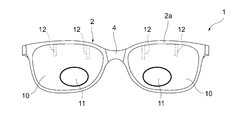
- FIG. 1 is an overall perspective view of electronic glasses according to an embodiment of the present invention. It is explanatory drawing for demonstrating the liquid crystal area
- the electronic spectacles 1 includes a lens 10 having a liquid crystal region (electrically active portion) 11, an electronic control module 20 (control unit) that controls power supplied to the liquid crystal region 11, and a mode for switching use modes.
- Touch sensor 30 In the present embodiment, as shown in FIGS. 1 and 2, the lens 10 is supported by the frame 2a of the front portion 2, and the electronic control module 20 and the touch sensor 30 are pivoted to the frame 2a via a hinge. It is embedded in a temple 3 that can be attached.
- the electronic control module 20 and the touch sensor 30 may be disposed only on one (eg, the right side) temple 3 or on both (left and right) temples 3.
- Each of the pair of left and right lenses 10 has a lens electrode 12 as shown in FIG. 2.
- the refractive index of the liquid crystal region 11 is obtained. It is possible to change the focal length.
- the liquid crystal region 11 has an optical characteristic that it becomes clouded when a voltage is applied.
- controlling the applied voltage to the liquid crystal region 11 to control the optical characteristics of the liquid crystal region 11 may be expressed as controlling the power supplied to the liquid crystal region 11.
- the electronic glasses 1 according to the present embodiment can notify the wearer that the use mode has been switched using the optical characteristics of the liquid crystal region 11.
- the liquid crystal region 11 of the lens 10 is disposed near the lower edge of the lens 10 and has an area smaller than the total area of the lens 10.
- the area of the liquid crystal region 11 can be set to about 5 to 50% (preferably about 12 to 13%) of the total area of the lens 10.
- the electronic control module 20 has a circuit board (not shown) on which various circuits are mounted, and a capacitive touch sensor 30 is connected to the circuit board.
- the circuit board is arranged inside the temple 3 and the touch sensor 30 is arranged outside the temple 3 so that the wearer of the electronic glasses 1 can easily operate the touch sensor 30. It has become.
- the electronic control module 20 controls the power supplied to the liquid crystal region 11 based on the operation of the touch sensor 30 and functions as a control unit in the present invention. Specific contents of control by the electronic control module 20 will be described in detail later.
- the touch sensor 30 is for switching the use mode of the electronic glasses 1 (from manual mode to auto mode and from auto mode to manual mode), and functions as a switching operation unit in the present invention.
- the manual mode is a mode in which power supply / cutoff to the liquid crystal region 11 is performed by operating the touch sensor 30, and corresponds to the first mode in the present invention.
- the auto mode is a mode for automatically supplying / cutting off electric power to the liquid crystal region 11 and corresponds to the second mode in the present invention.
- the electronic glasses 1 includes an acceleration sensor (not shown) that detects its own acceleration.
- the detection result of the acceleration sensor is used by the electronic control module 20 when controlling the power supplied to the liquid crystal region 11 in the auto mode.
- the electronic glasses 1 includes a battery 40 that stores power supplied to the liquid crystal region 11 of the lens 10, and a power amount sensor (not shown) that detects the amount of power stored in the battery 40.
- the battery 40 is embedded in the end portion of the temple 3. The detection result of the electric energy sensor is used when the power supplied to the liquid crystal region 11 is controlled by the electronic control module 20.
- the battery 40 may be disposed only at one end (for example, the left side) of the temple 3 or at both ends (left and right) of the temple 3.
- the electronic control module 20 of the electronic glasses 1 switches the use mode from the manual mode to the auto mode when there is a swipe operation (first operation) on the touch sensor 30 when the use mode is the manual mode.
- the electronic control module 20 controls the power supplied to the liquid crystal region 11 so that the liquid crystal region 11 becomes clouded in a specific manner (for example, a plurality of times at a predetermined time interval (for example, 0.25 seconds)).
- the liquid crystal region 11 is almost transparent, so that the wearer can visually recognize the cloudiness of the liquid crystal region 11. is there.
- the electronic control module 20 sets the use mode to the auto mode when there is a touch operation (second operation) for a predetermined time (for example, 1 second) to the touch sensor 30. Switch from to manual mode. At this time, the electronic control module 20 controls the power supplied to the liquid crystal region 11 so that the liquid crystal region 11 is clouded in a specific manner (for example, only once at a predetermined time interval (for example, 0.5 seconds)).
- the cloudiness of the liquid crystal region 11 when switching from the auto mode to the manual mode may be the same as or different from the cloudiness of the liquid crystal region 11 when switching from the manual mode to the auto mode. Note that in the auto mode before accepting the touch operation and the manual mode after the switching operation, the liquid crystal region 11 is in a substantially transparent state, so that the wearer can visually recognize the cloudiness of the liquid crystal region 11. is there.
- the electronic control module 20 supplies or cuts off the power to the liquid crystal region 11 when a touch operation is performed on the touch sensor 30 for a predetermined time (for example, 1 second) or less. Do. At this time, the touch sensor 30 functions as a liquid crystal operation unit for supplying / interrupting power to the liquid crystal region 11 in the manual mode.
- the electronic control module 20 controls the power supplied to the liquid crystal region 11 based on the detection result of the acceleration sensor when the use mode is the auto mode. For example, the electronic control module 20 supplies power to the liquid crystal region 11 to change the refractive index of the liquid crystal region 11 when acceleration that indicates that the wearer is facing down is detected by the acceleration sensor. It can be changed to a value for correcting myopia. On the other hand, the electronic control module 20 cuts off the power to the liquid crystal region 11 and detects the refractive index of the liquid crystal region 11 when the acceleration sensor detects that the wearer is facing upward. It can be restored to the default value.
- the electronic control module 20 displays the liquid crystal region 11 in a specific manner (for example, a predetermined time interval (for example, 0.5 The power supplied to the liquid crystal region 11 is controlled so as to make it cloudy a plurality of times or constantly). Thereby, the wearer of the electronic glasses 1 can know that the amount of electric power stored in the battery 40 is small.
- a plurality of threshold values for determining the electric energy may be set, and the cloudiness may be changed according to the level of the electric energy.
- the liquid crystal region 11 when the electric energy of the battery 40 is less than the first threshold, the liquid crystal region 11 is clouded a plurality of times at predetermined time intervals, and the electric energy of the battery 40 is less than the second threshold (less than the first threshold). In this case, the liquid crystal region 11 can be always clouded.
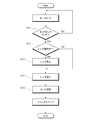
- the electronic control module 20 determines whether or not a swipe operation (first operation) has been performed on the touch sensor 30 (swipe determination step: S1). When the electronic control module 20 determines that a swipe operation has been performed in the swipe determination step S1, the electronic control module 20 determines whether power is supplied to the liquid crystal region 11 of the lens 10 (lens operation determination step: S2). ) When it is determined that power is supplied to the liquid crystal region 11, the power supply to the liquid crystal region 11 is temporarily stopped (lens stop step: S3).
- the electronic control module 20 that has undergone the lens stopping step S3 controls the power supplied to the liquid crystal region 11 so that the liquid crystal region 11 becomes clouded a plurality of times at a predetermined time interval (for example, 0.25 seconds) (lens blinking step: S4). ). Thereafter, the electronic control module 20 switches the use mode of the electronic glasses 1 from the manual mode to the auto mode (mode switching step: S5), and controls the power supplied to the liquid crystal region 11 based on the detection result of the acceleration sensor. .
- the electronic control module 20 determines whether or not there has been a touch operation (second operation) that exceeds a predetermined time (for example, 1 second) on the touch sensor 30 ( Touch determination step: S11).
- a touch operation for example, 1 second
- the electronic control module 20 determines whether power is supplied to the liquid crystal region 11 of the lens 10 (lens operation). Determination step: S12) When it is determined that power is supplied to the liquid crystal region 11, the power supply to the liquid crystal region 11 is temporarily stopped (lens stop step: S13).
- the electronic control module 20 that has undergone the lens stopping step S13 controls the power supplied to the liquid crystal region 11 so that the liquid crystal region 11 becomes clouded only once at a predetermined time interval (for example, 0.5 seconds) (lens lighting step: S14). Thereafter, the electronic control module 20 switches the use mode of the electronic glasses 1 from the auto mode to the manual mode (mode switching step: S15), and controls the power supplied to the liquid crystal region 11 based on the touch operation on the touch sensor 30. To do.
- a predetermined time interval for example, 0.5 seconds
- the electronic control module 20 supplies the power supplied to the liquid crystal region 11.
- the liquid crystal region 11 can be clouded in a specific manner (for example, a plurality of times at predetermined time intervals). Therefore, the wearer of the electronic glasses 1 can know that the use mode has been switched from the manual mode to the auto mode due to the cloudiness of the liquid crystal region 11 of the lens 10 in front of the eyes. At this time, since the liquid crystal region 11 has an area smaller than the entire area of the lens 10, even if the liquid crystal region 11 is clouded, the entire lens 10 is not clouded. Can be prevented.
- the electronic control module 20 is switched to the liquid crystal region 11.
- the liquid crystal region 11 can be clouded in a specific manner (for example, only once at a predetermined time interval) by controlling the supplied power. Therefore, the wearer of the electronic glasses 1 can know that the use mode has been switched from the auto mode to the manual mode due to the cloudiness of the liquid crystal region 11 of the lens 10 in front of the eyes. At this time, even if the liquid crystal region 11 is clouded, the entire lens 10 is not clouded, so that the visual field of the wearer of the electronic glasses 1 can be prevented from being disturbed.
- a specific mode of the liquid crystal region 11 when the mode is switched from the auto mode to the manual mode (for example, only once at a predetermined time interval), and the liquid crystal region 11 when the mode is switched from the manual mode to the auto mode.
- a specific mode (for example, a plurality of times at a predetermined time interval) is a mode that can be visually recognized and different from each other, so that the wearer can identify which mode has been changed by the switching operation. it can.
- the liquid crystal region 11 is disposed near the lower edge of the lens 10, and the area of the liquid crystal region 11 is 5% to 50% of the total area of the lens 10. Since it is set, the visual field near the center of the lens 10 can be secured even when the liquid crystal region 11 is clouded.
- the electronic control module 20 can control the power supplied to the liquid crystal region 11 to make the liquid crystal region 11 cloudy in a specific manner. Therefore, the wearer of the electronic glasses 1 can know that the amount of electric power stored in the battery 40 is small due to the cloudiness of the liquid crystal region 11 of the lens 10 in front of the eyes. At this time, even if the liquid crystal region 11 is clouded, the entire lens 10 is not clouded, so that the visual field of the wearer of the electronic glasses 1 can be prevented from being disturbed.
- the switching operation unit may be disposed on a hinge connecting the frame 2a and the temple 3.
- a mechanical switch may be employed as the switching operation unit, and the mechanical switch may be disposed on the bridge 4 (see FIGS. 1 and 2) of the front part 2 of the electronic glasses 1.
- the mechanical switch may also serve as a liquid crystal operation unit.
- the electronic control module 20 can be configured to perform various controls in accordance with operations on the mechanical switch.
- the use mode when the first operation is performed on the mechanical switch, the use mode is switched from the manual mode to the auto mode, and at this time, the power supplied to the liquid crystal region 11 so that the liquid crystal region 11 is clouded in a specific manner.
- the electronic control module 20 can be configured to control On the other hand, when there is a second operation on the mechanical switch, the use mode is switched from the auto mode to the manual mode, and at this time, the power supplied to the liquid crystal region 11 so that the liquid crystal region 11 becomes clouded in a specific manner.
- the electronic control module 20 can also be configured to control
- the electronic control module 20 may be configured to supply or cut off power to the liquid crystal region 11 when there is a third operation with the mechanical switch.
- the touch sensor 30 was made to function as a switching operation part and a liquid crystal operation part, the touch sensor 30 and the mechanical switch were used together, and one (for example, touch sensor 30) was switched. It is also possible to function as an operation unit and allow the other (for example, a mechanical switch) to function as a liquid crystal operation unit.
- the mode in which the liquid crystal region 11 is clouded at the time of mode switching is illustrated, but other modes can also be adopted.
- the transmittance is changed by scattering light by the liquid crystal region 11, but by applying an electric field or current, for example, a colored state colored from orange or blue to a transparent state that is nearly transparent
- the electrochromic material (electron active portion) that changes into the shape may be disposed in the liquid crystal region 11 in the lens of the electronic spectacles or in a region other than the liquid crystal region 11 in the lens.
- the electrochromic material may be a liquid crystal or other material.
- the control unit controls the power supplied to the electrochromic material, and the electrochromic material is changed in the first mode (for example, a predetermined mode).
- the control unit controls the power supplied to the electrochromic material to change the electrochromic material to the second mode. It can be colored in a manner (eg, multiple times at predetermined time intervals).
- the control unit controls the power supplied to the electrochromic material, and the electrochromic material is colored with a first color (for example, orange),
- the control unit can control the power supplied to the electrochromic material to color the electrochromic material with a second color (for example, blue). In this way, the wearer can identify the switching of the use mode according to the specific coloring state of the lens.
- liquid crystal region 11 is disposed only at one position near the lower edge of each lens 10 .
- a use mode can be provided. It is also possible to selectively determine the liquid crystal region 11 to be changed to a specific state according to the switching destination.
- the control unit when the liquid crystal region 11 is arranged separately at a position near the left edge and a position near the right edge of each lens 10 and the use mode is switched from the auto mode to the manual mode, the control unit ( When the electronic control module 20) causes the liquid crystal region 11 on the left side of each lens 10 to become clouded in the first mode and is switched from the manual mode to the auto mode, the control unit controls the liquid crystal region 11 on the right side of each lens 10. May be clouded in the second embodiment. In this case, since the places of the left and right liquid crystal regions 11 are different and the wearer can identify the mode of the transition destination at the location in the lens 10, the left and right liquid crystal regions 11 may be clouded in the same manner.
- a use mode is changed from 1st mode to 2nd mode.
- the change of the refractive index can be notified to the wearer by making the liquid crystal region 11 cloudy in a specific manner based on the detection result of the acceleration sensor.
- the control unit electronic control module 20 moves to the liquid crystal region 11 when acceleration is detected by the acceleration sensor to indicate that the wearer is facing down when the use mode is the auto mode.
- the control unit supplies power to the liquid crystal region 11 and causes the liquid crystal region 11 to become clouded in a specific manner. Thereafter, the power to the liquid crystal region 11 can be cut off to control the refractive index of the liquid crystal region 11 to a default value.
- the posture of the wearer is detected using various sensors for detecting the posture, such as an angular velocity sensor and a gyro sensor, without being limited to the acceleration sensor. be able to.
- the control unit can control the cloudiness of the liquid crystal region 11 according to the detection result of the posture detection sensor.
- the use mode (manual mode and auto mode) of the electronic glasses 1 was adopted as a plurality of modes
- the power modes (power on mode, sleep mode, power supply) of the electronic glasses 1 were shown. Off mode) can be adopted as a plurality of modes.
- the control unit electronic control module 20
- the control unit can control the liquid crystal region 11 to become clouded in a predetermined manner when these power modes are switched.
- power-on mode power is supplied to various sensors such as the touch sensor 30, and a use mode switching operation from the wearer can be received to control the liquid crystal region 11.
- the sleep mode is a mode in which some functions of the electronic glasses 1 are turned off to save power compared to the power-on mode (for example, the touch sensor 30 does not function in this mode).
- the power-off mode is a mode in which all functions of the electronic glasses 1 are turned off.
- different modes can be used in combination.
- the liquid crystal state is visually recognized.
- the specific mode may be changed to be possible, and this specific mode may be changed based on the remaining battery level (second parameter).
- the control unit electronic control module 20
- the control unit measures the remaining amount of the battery and sets the level of the remaining amount of the battery to level I (large: 50%). More than 100%), level II (less: 20% or more and less than 50%), and level III (charge required: less than 20%) can be determined in three stages.
- the control unit controls the liquid crystal region 11 to be clouded in a different manner according to the measured remaining battery levels I to III (for example, when the level is I, it is clouded once and the level II , It can be clouded twice, and if it is level III, it can be clouded three times).
- the remaining amount of the battery can be measured and the liquid crystal region 11 can be controlled in a manner corresponding to the remaining amount of the battery. It is. As the liquid crystal region 11 becomes cloudy in this way, the wearer can recognize that the power mode (or use mode) has changed, and the remaining battery level can be determined by the number of times the liquid crystal region 11 becomes cloudy. Can be recognized. That is, when the liquid crystal region 11 becomes cloudy in a specific manner, the wearer can recognize information on two parameters such as power supply and the remaining amount of the battery (or the use state and the remaining amount of the battery). Become.
- the electronic glasses 1 were illustrated as eyewear, the eyewear to which this invention is applied is not restricted to this, It is mounted
- the present invention is not limited to the above-described embodiments, and those in which those skilled in the art appropriately modify the design are included in the scope of the present invention as long as they have the features of the present invention. .
- each element included in the embodiment and its arrangement, material, condition, shape, size, and the like are not limited to those illustrated, and can be appropriately changed.
- each element with which the said embodiment is provided can be combined as much as technically possible, and the combination of these is also included in the scope of the present invention as long as it includes the features of the present invention.
Landscapes
- Physics & Mathematics (AREA)
- General Physics & Mathematics (AREA)
- Optics & Photonics (AREA)
- Nonlinear Science (AREA)
- Health & Medical Sciences (AREA)
- Ophthalmology & Optometry (AREA)
- General Health & Medical Sciences (AREA)
- Chemical & Material Sciences (AREA)
- Crystallography & Structural Chemistry (AREA)
- Liquid Crystal (AREA)
- Eyeglasses (AREA)
Abstract
着用者の視野を妨げることなく、使用モードが切り替えられたことを着用者に知らせることができる電子眼鏡を提供する。電力の供給により白濁するように構成された液晶領域11を有するレンズ10と、液晶領域11への印加電圧を制御する制御部20と、使用モードを切り替えるための切替操作部30と、を備える電子眼鏡1である。液晶領域11は、レンズ10の全面積よりも小さい面積を有し、制御部20は、切替操作部30の操作により使用モードが第一のモードから第二のモードへと切り替えられた場合に、液晶領域11を特定の態様で白濁させるように液晶領域11への印加電圧を制御する。
Description
本発明は、電子眼鏡に関する。
従来より、レンズの焦点距離を電気的に制御することを可能にした遠近両用の電子眼鏡が提案され、実用化されている。電子眼鏡は、電力が供給されることにより屈折率が変化するように構成された液晶素子を有する液晶レンズ、この液晶レンズに供給される電力を蓄える小型電池、所定の操作を行うためのスイッチ、等を備えるのが一般的である。
現在においては、このような電子眼鏡に類似した立体表示用の液晶シャッタ眼鏡において、電源の投入や電池切れの発生を、液晶シャッタの開閉によって眼鏡の着用者に知らせる技術が提案されている(例えば特許文献1及び2参照)。
ところで、近年においては、所定のスイッチを操作することにより、電子眼鏡の使用モードを(例えばマニュアルモードからオートモードへと)切り替える技術が提案されている。しかし、現状では、電子眼鏡の使用モードが切り替えられたことを眼鏡の着用者に認識させるための有効な手段が提案されていない。仮に、特許文献1及び2に開示されたような手段を採用すると、電子眼鏡の液晶レンズ全体が一時的に閉じられてしまい、着用者の視野を妨げてしまうという問題がある。
本発明は、かかる事情に鑑みてなされたものであり、着用者の視野を妨げることなく、使用モードが切り替えられたことを着用者に知らせることができる電子眼鏡を提供することを目的とする。
前記目的を達成するため、本発明に係る電子眼鏡は、電力の供給により白濁するように構成された液晶領域を有するレンズと、液晶領域への印加電圧を制御する制御部と、使用モードを切り替えるための切替操作部と、を備える電子眼鏡であって、液晶領域は、レンズの全面積よりも小さい面積を有し、制御部は、切替操作部の操作により使用モードが第一のモードから第二のモードへと切り替えられた場合に、液晶領域を特定の態様で(例えば所定の時間間隔で複数回)白濁させるように液晶領域への印加電圧を制御するものである。
かかる構成を採用すると、切替操作部の操作により使用モードが第一のモード(例えばマニュアルモード)から第二のモード(例えばオートモード)へと切り替えられた場合に、制御部が液晶領域への印加電圧を制御して液晶領域を特定の態様で(例えば所定の時間間隔で複数回)白濁させることができる。従って、本電子眼鏡の着用者は、眼前にあるレンズの液晶領域の白濁により、使用モードが第一のモードから第二のモードへと切り替えられたことを知ることができる。この際、液晶領域はレンズの全面積よりも小さい面積を有することから、液晶領域が白濁してもレンズ全体が白濁することはないため、電子眼鏡の着用者の視野が妨げられることを防ぐことができる。
また、本発明に係る第一のアイウェアは、液晶領域を有するレンズと、液晶領域への印加電圧を制御する制御部と、を備え、複数のモードを有するアイウェアであって、液晶領域は、レンズの全面積よりも小さい面積を有し、制御部は、複数のモードのうち第一のモードから第二のモードへの切り替えを検出した場合に、液晶領域を特定の態様で白濁させるように液晶領域への印加電圧を制御するものである。本アイウェアは、モードの切り替えを受け付けるための切替操作部をさらに備えることができる。かかる場合において、制御部は、切替操作部の操作により第一のモードから第二のモードへの切り替えが指示された場合に、液晶領域を所定の時間間隔で複数回白濁させるように液晶領域への印加電圧を制御することができる。第一のモードとしては、液晶領域への電力の供給/遮断を液晶操作部の操作で行うマニュアルモードを採用することができ、第二のモードとしては、液晶領域への電力の供給/遮断を自動で行うオートモードを採用することができる。
かかる構成を採用すると、切替操作部の操作によりモードが第一のモード(例えばマニュアルモード)から第二のモード(例えばオートモード)へと切り替えられた場合に、制御部が液晶領域への印加電圧を制御して液晶領域を特定の態様で(例えば所定の時間間隔で複数回)白濁させることができる。従って、本アイウェアの着用者は、眼前にあるレンズの液晶領域の白濁により、モードが第一のモードから第二のモードへと切り替えられたことを知ることができる。この際、液晶領域はレンズの全面積よりも小さい面積を有することから、液晶領域が白濁してもレンズ全体が白濁することはないため、アイウェアの着用者の視野が妨げられることを防ぐことができる。
本発明に係る第一のアイウェアにおいて、切替操作部としてタッチセンサを採用することができる。かかる場合において、タッチセンサへの第一の操作があった場合に、モードを第一のモードから第二のモードへと切り替える一方、タッチセンサへの第二の操作があった場合に、モードを第二のモードから第一のモードへと切り替える制御部を採用することができる。
かかる構成を採用すると、タッチセンサへの第一の操作(例えばスワイプ操作)により、モードを第一のモードから第二のモードへと切り替える一方、タッチセンサへの第二の操作(例えばタッチ操作)により、モードを第二のモードから第一のモードへと切り替えることができる。
本発明に係る第一のアイウェアにおいて、液晶操作部としてタッチセンサを採用することができる。かかる場合において、モードがマニュアルモードであるときにタッチセンサへの所定時間以下のタッチ操作があった場合に、液晶領域への電力の供給又は遮断を行う制御部を採用することができる。この際、切替操作部は、液晶操作部を兼ねることができる。
本発明に係る第一のアイウェアにおいて、電子眼鏡の加速度を検出する加速度センサを備えることができる。かかる場合において、モードがオートモードであるときに、加速度センサでの検出結果に基づいて液晶領域への印加電圧を制御する制御部を採用することができる。
本発明に係る第一のアイウェアにおいて、切替操作部をテンプルに配置することができる。
本発明に係る第一のアイウェアにおいて、液晶領域を、レンズの縁部寄りの位置に配置し、液晶領域の面積を、レンズの全面積の5%~50%に設定することができる。
かかる構成を採用すると、液晶領域がレンズの縁部寄りの位置に配置され、液晶領域の面積がレンズの全面積の5%~50%に設定されているため、液晶領域が白濁した場合においてもレンズの中央付近の視野を確保することができる。
本発明に係る第一のアイウェアにおいて、液晶領域に供給される電力を蓄えるバッテリと、バッテリに蓄えられた電力の量を検出する電力量センサと、を備えることができる。かかる場合において、電力量センサで検出された電力の量が所定の閾値未満である場合に、液晶領域を特定の態様で白濁させるように液晶領域への印加電圧を制御する制御部を採用することができる。
かかる構成を採用すると、電力量センサで検出された電力の量(バッテリに蓄えられた電力の量)が所定の閾値未満である場合に、制御部が液晶領域への印加電圧を制御して液晶領域を特定の態様で白濁させることができる。従って、本電子眼鏡の着用者は、眼前にあるレンズの液晶領域の白濁により、バッテリに蓄えられた電力の量が残り少ないことを知ることができる。この際、液晶領域が白濁してもレンズ全体が白濁することはないため、電子眼鏡の着用者の視野が妨げられることを防ぐことができる。
また、本発明に係る第二のアイウェアは、電力の供給により光学特性が変化するように構成された電気活性部を有するレンズと、電気活性部の光学特性を制御する制御部と、を備え、複数のモードを有するアイウェアであって、制御部は、複数のモードのうち第一のモードから第二のモードへの切り替えを検出した場合に、電気活性部を第一のモードにおける態様から第二のモードにおける態様へと移行させ、この移行の際に、電気活性部を視認可能な特定の態様とするように電気活性部の光学特性を制御するものである。視認可能な特定の態様としては、電気活性部が白濁若しくは着色されることにより、又は、電気活性部の透過率が変化することにより、視認される態様を採用することができる。電子活性部の第一のモードにおける態様及び第二のモードにおける態様としては、電子活性部がほぼ透明な状態となる態様を採用することができる。
かかる構成を採用すると、制御部は、複数のモードのうち第一のモード(例えばマニュアルモード)から第二のモード(例えばオートモード)への切り替えを検出した場合に、電気活性部を第一のモードにおける態様から第二のモードにおける態様へと移行させることができる。そして制御部は、この移行の際に、電気活性部を視認可能な特定の態様(例えば電気活性部が白濁若しくは着色されることにより、又は、電気活性部の透過率が変化することにより、視認される態様)とするように電気活性部の光学特性を制御することができる。従って、本アイウェアの着用者は、眼前にあるレンズの電気活性部により、モードが第一のモードから第二のモードへと切り替えられたことを知ることができる。
本発明に係る第二のアイウェアにおいて、ユーザからの操作を受け付ける切替操作部をさらに備えることができる。かかる場合において、ユーザの切替操作部に対する操作に応じて、第一のモードから第二のモードへの切り替えを検出する制御部を採用することができる。また、ユーザの操作を受け付けることなく、第一のモードから第二のモードへの切り替えを検出する制御部を採用してもよい。
本発明に係る第二のアイウェアにおいて、姿勢検出センサをさらに備えることができる。かかる場合において、姿勢検出センサでの検出結果に基づいて第一のモードから第二のモードへの切り替えを検出する制御部を採用することができる。
本発明に係る第二のアイウェアにおいて、第一のモード及び第二のモードとして、アイウェアの使用モード又は電力モードを採用することができる。
本発明に係る第二のアイウェアにおいて、第一のモード及び第二のモードとして、第一のパラメータに関するモードを採用することができる。かかる場合において、第一のモードにおける態様及び第二のモードにおける態様を、第一のパラメータとは異なる第二のパラメータによって決定することができる。第一のパラメータに関するモードとしては、アイウェアの使用モード又は電力モードを採用することができる。第二のパラメータとして、アイウェアのバッテリの残量を採用することができる。
本発明によれば、着用者の視野を妨げることなく、使用モードが切り替えられたことを着用者に知らせることができる電子眼鏡を提供することが可能となる。
以下、図面を参照して、本発明の実施形態について説明する。なお、以下の実施形態はあくまでも好適な適用例であって、本発明の適用範囲がこれに限定されるものではない。
まず、図1及び図2を用いて、本発明の実施形態に係る電子眼鏡1の構成について説明する。
本実施形態に係る電子眼鏡1は、液晶領域(電気活性部)11を有するレンズ10と、液晶領域11への供給電力を制御する電子制御モジュール20(制御部)と、使用モードを切り替えるためのタッチセンサ30と、を備えている。本実施形態においては、図1及び図2に示すように、レンズ10はフロント部2のフレーム2aによって支持されており、電子制御モジュール20及びタッチセンサ30は、フレーム2aにヒンジを介して回動可能に取り付けられたテンプル3に埋め込まれている。なお、電子制御モジュール20及びタッチセンサ30は、一方(例えば右側)のテンプル3のみに配置してもよく、双方(左右)のテンプル3に配置してもよい。
左右一対のレンズ10は、各々、図2に示すようにレンズ電極12を有しており、このレンズ電極12を介して液晶領域11に電圧を印加又は除去することにより、液晶領域11の屈折率を変化させ、ひいては焦点距離を変化させることができるようになっている。また、液晶領域11は、電圧印加時に白濁するという光学特性を有している。本実施形態では、液晶領域11への印加電圧を制御して液晶領域11の光学特性を制御することを、液晶領域11への供給電力を制御する、と表現することがある。本実施形態に係る電子眼鏡1は、かかる液晶領域11の光学特性を利用して、使用モードが切り替えられたことを着用者に知らせることができるようにしたものである。
レンズ10の液晶領域11は、図2に示すように、レンズ10の下縁部寄りの位置に配置されており、レンズ10の全面積よりも小さい面積を有している。液晶領域11の面積は、レンズ10の全面積の5~50%程度(好ましくは12~13%程度)に設定することができる。
電子制御モジュール20は、各種回路が実装された(図示されていない)回路基板を有しており、この回路基板には、静電容量式のタッチセンサ30が接続されている。本実施形態においては、回路基板をテンプル3の内側に配置し、タッチセンサ30をテンプル3の外側に配置することにより、電子眼鏡1の着用者がタッチセンサ30を容易に操作することができるようになっている。電子制御モジュール20は、タッチセンサ30の操作等に基づいて液晶領域11への供給電力を制御するものであり、本発明における制御部として機能する。電子制御モジュール20による具体的な制御の内容については、後に詳述することとする。
タッチセンサ30は、電子眼鏡1の使用モードを(マニュアルモードからオートモードへ及びオートモードからマニュアルモードへ)切り替えるためのものであり、本発明における切替操作部として機能する。なお、マニュアルモードは、液晶領域11への電力の供給/遮断をタッチセンサ30の操作で行うモードであり、本発明における第一のモードに相当するものである。一方、オートモードは、液晶領域11への電力の供給/遮断を自動で行うモードであり、本発明における第二のモードに相当するものである。
また、本実施形態に係る電子眼鏡1は、自身の加速度を検出する(図示されていない)加速度センサを備えている。加速度センサでの検出結果は、電子制御モジュール20によって、オートモードで液晶領域11への供給電力を制御する際に使用される。
また、本実施形態に係る電子眼鏡1は、レンズ10の液晶領域11に供給される電力を蓄えるバッテリ40と、バッテリ40に蓄えられた電力の量を検出する(図示されていない)電力量センサと、を備えている。本実施形態においては、図1に示すように、バッテリ40がテンプル3の端部に埋め込まれている。電力量センサでの検出結果は、電子制御モジュール20によって、液晶領域11への供給電力を制御する際に使用される。なお、バッテリ40は、一方(例えば左側)のテンプル3の端部のみに配置してもよく、双方(左右)のテンプル3の端部に配置してもよい。
次に、本実施形態に係る電子眼鏡1の電子制御モジュール20による具体的な制御の内容について説明する。
電子眼鏡1の電子制御モジュール20は、使用モードがマニュアルモードであるときにタッチセンサ30へのスワイプ操作(第一の操作)があった場合に、使用モードをマニュアルモードからオートモードへと切り替える。このとき、電子制御モジュール20は、液晶領域11を特定の態様で(例えば所定の時間間隔(例えば0.25秒)で複数回)白濁させるように液晶領域11への供給電力を制御する。なお、スワイプ操作を受け付ける前のマニュアルモードと、切り替え操作後のオートモードと、においては、液晶領域11はほぼ透明な状態であるため、着用者は液晶領域11の白濁を視認することが可能である。
また、電子制御モジュール20は、使用モードがオートモードであるときにタッチセンサ30への所定時間(例えば1秒)を超えるタッチ操作(第二の操作)があった場合に、使用モードをオートモードからマニュアルモードへと切り替える。このとき、電子制御モジュール20は、液晶領域11を特定の態様で(例えば所定の時間間隔(例えば0.5秒)で一回のみ)白濁させるように液晶領域11への供給電力を制御する。オートモードからマニュアルモードへと切り替わるときの液晶領域11の白濁態様は、マニュアルモードからオートモードへと切り替わるときの液晶領域11の白濁態様と同一でもよく、異なっていてもよい。なお、タッチ操作を受け付ける前のオートモードと、切り替え操作後のマニュアルモードと、においては、液晶領域11はほぼ透明な状態であるため、着用者は液晶領域11の白濁を視認することが可能である。
また、電子制御モジュール20は、使用モードがマニュアルモードであるときにタッチセンサ30への所定時間(例えば1秒)以下のタッチ操作があった場合に、液晶領域11への電力の供給又は遮断を行う。この際、タッチセンサ30は、マニュアルモードにおいて液晶領域11への電力の供給/遮断を行うための液晶操作部として機能する。
また、電子制御モジュール20は、使用モードがオートモードであるときに、加速度センサでの検出結果に基づいて液晶領域11への供給電力を制御する。例えば、電子制御モジュール20は、着用者が下を向いたことを示すような加速度が加速度センサによって検出された場合には、液晶領域11へと電力を供給して、液晶領域11の屈折率を近視矯正用の値に変化させることができる。一方、電子制御モジュール20は、着用者が上を向いたことを示すような加速度が加速度センサで検出された場合には、液晶領域11への電力を遮断して、液晶領域11の屈折率をデフォルトの値に戻すことができる。
また、電子制御モジュール20は、電力量センサで検出されたバッテリ40の電力の量が所定の閾値未満である場合に、液晶領域11を特定の態様で(例えば所定の時間間隔(例えば0.5秒)で複数回又は常時)白濁させるように液晶領域11への供給電力を制御する。これにより、電子眼鏡1の着用者は、バッテリ40に蓄えられた電力の量が残り少ないことを知ることができる。なお、電力量判定用の閾値を複数設定しておき、電力量のレベルに応じて白濁態様を変化させてもよい。例えば、バッテリ40の電力量が第一の閾値未満である場合に液晶領域11を所定の時間間隔で複数回白濁させ、バッテリ40の電力量が(第一の閾値より小さい)第二の閾値未満である場合に液晶領域11を常時白濁させることもできる。
続いて、図3及び図4のフローチャートを用いて本実施形態に係る電子眼鏡1の電子制御モジュール20によるモード切替表示制御の例について具体的に説明する。
<マニュアルモードからオートモードへの切替>
まず、図3のフローチャートを用いて、電子眼鏡1の使用モードがマニュアルモードからオートモードへと切り替えるときの切替表示制御について説明する。
まず、図3のフローチャートを用いて、電子眼鏡1の使用モードがマニュアルモードからオートモードへと切り替えるときの切替表示制御について説明する。
電子眼鏡1の使用モードがマニュアルモードである場合において、電子制御モジュール20は、タッチセンサ30へのスワイプ操作(第1の操作)があったか否かを判定する(スワイプ判定工程:S1)。そして、電子制御モジュール20は、スワイプ判定工程S1においてスワイプ操作があったものと判定した場合に、レンズ10の液晶領域11に電力が供給されているか否かを判定し(レンズ動作判定工程:S2)、液晶領域11に電力が供給されていると判定した場合には液晶領域11への電力供給を一時的に停止させる(レンズ停止工程:S3)。
レンズ停止工程S3を経た電子制御モジュール20は、液晶領域11を所定の時間間隔(例えば0.25秒)で複数回白濁させるように液晶領域11への供給電力を制御する(レンズ点滅工程:S4)。その後、電子制御モジュール20は、電子眼鏡1の使用モードをマニュアルモードからオートモードへと切り替え(モード切替工程:S5)、加速度センサでの検出結果に基づいて液晶領域11への供給電力を制御する。
<オートモードからマニュアルモードへの切替>
次に、図4のフローチャートを用いて、電子眼鏡1の使用モードがオートモードからマニュアルモードへと切り替えるときの切替表示制御について説明する。
次に、図4のフローチャートを用いて、電子眼鏡1の使用モードがオートモードからマニュアルモードへと切り替えるときの切替表示制御について説明する。
電子眼鏡1の使用モードがオートモードである場合において、電子制御モジュール20は、タッチセンサ30への所定時間(例えば1秒)を超えるタッチ操作(第二の操作)があったか否かを判定する(タッチ判定工程:S11)。そして、電子制御モジュール20は、タッチ判定工程S11において所定時間を超えるタッチ操作があったものと判定した場合に、レンズ10の液晶領域11に電力が供給されているか否かを判定し(レンズ動作判定工程:S12)、液晶領域11に電力が供給されていると判定した場合には液晶領域11への電力供給を一時的に停止させる(レンズ停止工程:S13)。
レンズ停止工程S13を経た電子制御モジュール20は、液晶領域11を所定の時間間隔(例えば0.5秒)で一回のみ白濁させるように液晶領域11への供給電力を制御する(レンズ点灯工程:S14)。その後、電子制御モジュール20は、電子眼鏡1の使用モードをオートモードからマニュアルモードへと切り替え(モード切替工程:S15)、タッチセンサ30へのタッチ操作に基づいて液晶領域11への供給電力を制御する。
以上説明した実施形態に係る電子眼鏡1においては、タッチセンサ30へのスワイプ操作により使用モードがマニュアルモードからオートモードへと切り替えられた場合に、電子制御モジュール20が液晶領域11への供給電力を制御して液晶領域11を特定の態様で(例えば所定の時間間隔で複数回)白濁させることができる。従って、電子眼鏡1の着用者は、眼前にあるレンズ10の液晶領域11の白濁により、使用モードがマニュアルモードからオートモードへと切り替えられたことを知ることができる。この際、液晶領域11はレンズ10の全面積よりも小さい面積を有することから、液晶領域11が白濁してもレンズ10全体が白濁することはないため、電子眼鏡1の着用者の視野が妨げられることを防ぐことができる。
また、以上説明した実施形態に係る電子眼鏡1においては、タッチセンサ30へのタッチ操作により使用モードがオートモードからマニュアルモードへと切り替えられた場合においても、電子制御モジュール20が液晶領域11への供給電力を制御して液晶領域11を特定の態様で(例えば所定の時間間隔で一回のみ)白濁させることができる。従って、電子眼鏡1の着用者は、眼前にあるレンズ10の液晶領域11の白濁により、使用モードがオートモードからマニュアルモードへと切り替えられたことを知ることができる。この際、液晶領域11が白濁してもレンズ10全体が白濁することはないため、電子眼鏡1の着用者の視野が妨げられることを防ぐことができる。また、オートモードからマニュアルモードへと切り替えられた場合の液晶領域11の特定の態様(例えば所定の時間間隔で一回のみ)と、マニュアルモードからオートモードへと切り替えられた場合の液晶領域11の特定の態様(例えば所定の時間間隔で複数回)と、が各々視認できる態様であって互いに異なる態様であることにより、着用者は、切り替え動作により、どのモードへ移行したのかを識別することができる。
また、以上説明した実施形態に係る電子眼鏡1においては、液晶領域11がレンズ10の下縁部寄りの位置に配置され、液晶領域11の面積がレンズ10の全面積の5%~50%に設定されているため、液晶領域11が白濁した場合においてもレンズ10の中央付近の視野を確保することができる。
また、以上説明した実施形態に係る電子眼鏡1においては、電力量センサで検出された電力の量(バッテリ40に蓄えられた電力の量)が所定の閾値未満である場合に、電子制御モジュール20が液晶領域11への供給電力を制御して液晶領域11を特定の態様で白濁させることができる。従って、電子眼鏡1の着用者は、眼前にあるレンズ10の液晶領域11の白濁により、バッテリ40に蓄えられた電力の量が残り少ないことを知ることができる。この際、液晶領域11が白濁してもレンズ10全体が白濁することはないため、電子眼鏡1の着用者の視野が妨げられることを防ぐことができる。
なお、以上の実施形態においては、電子眼鏡1のテンプル3に配置されたタッチセンサ30を切替操作部として採用した例を示したが、切替操作部の構成はこれに限られるものではない。例えば、フレーム2aとテンプル3とを接続するヒンジに切替操作部を配置してもよい。また、切替操作部としてメカニカルスイッチを採用し、このメカニカルスイッチを電子眼鏡1のフロント部2のブリッジ4(図1及び図2参照)に配置することもできる。また、このメカニカルスイッチが液晶操作部を兼ねることにしてもよい。切替操作部としてメカニカルスイッチを採用した場合には、メカニカルスイッチへの操作に応じて各種制御を行うように電子制御モジュール20を構成することができる。
例えば、メカニカルスイッチへの第一の操作があった場合に、使用モードをマニュアルモードからオートモードへと切り替え、この際、液晶領域11を特定の態様で白濁させるように液晶領域11への供給電力を制御するように電子制御モジュール20を構成することができる。一方、メカニカルスイッチへの第二の操作があった場合に、使用モードをオートモードからマニュアルモードへと切り替え、この際、液晶領域11を特定の態様で白濁させるように液晶領域11への供給電力を制御するように電子制御モジュール20を構成することもできる。また、使用モードがマニュアルモードであるときにメカニカルスイッチでの第三の操作があった場合に、液晶領域11への電力の供給又は遮断を行うように電子制御モジュール20を構成してもよい。
また、以上の実施形態においては、タッチセンサ30を切替操作部及び液晶操作部として機能させた例を示したが、タッチセンサ30とメカニカルスイッチとを併用し、一方(例えばタッチセンサ30)を切替操作部として機能させ、他方(例えばメカニカルスイッチ)を液晶操作部として機能させることもできる。
また、以上の実施形態においては、モードの切り替え時に液晶領域11を白濁させる態様を例示したが、他の態様を採用することもできる。白濁の場合は、液晶領域11によって光を散乱させて透過率を変化させているが、例えば、電界又は電流を加えることにより、透明に近い透過状態から、オレンジ色や青色に着色された着色状態へと変化するエレクトロクロミック材料(電子活性部)を、電子眼鏡のレンズ内の液晶領域11又はレンズ内の液晶領域11以外の領域に配置してもよい。エレクトロクロミック材料は液晶であってもよく、それ以外の材料であってもよい。使用モードがオートモードからマニュアルモードへと切り替えられた場合には、制御部(電子制御モジュール20)がエレクトロクロミック材料への供給電力を制御して、エレクトロクロミック材料を第一の態様で(例えば所定の時間間隔で一回のみ)着色させ、使用モードがマニュアルモードからオートモードへと切り替えられた場合には、制御部がエレクトロクロミック材料への供給電力を制御して、エレクトロクロミック材料を第二の態様で(例えば所定の時間間隔で複数回)着色させることができる。また、使用モードがオートモードからマニュアルモードへと切り替えられた場合に、制御部がエレクトロクロミック材料への供給電力を制御して、エレクトロクロミック材料を第一の色(例えばオレンジ色)で着色させ、使用モードがマニュアルモードからオートモードへと切り替えられた場合に、制御部がエレクトロクロミック材料への供給電力を制御して、エレクトロクロミック材料を第二の色(例えば青色)で着色させることもできる。このようにすると、レンズの特定の着色状態により、着用者は使用モードの切り替えを識別することが可能である。
また、以上の実施形態においては、液晶領域11を各レンズ10の下縁部寄りの位置に一箇所だけ配置した例を示したが、液晶領域11を各レンズ10に複数設けることにより、使用モードの切り替え先に応じて特定の状態へと変化させる液晶領域11を選択的に決定することも可能である。例えば、液晶領域11を各レンズ10の左縁部寄りの位置と右縁部寄りの位置に離隔させて配置し、使用モードがオートモードからマニュアルモードへと切り替えられた場合には、制御部(電子制御モジュール20)が各レンズ10の左側の液晶領域11を第一の態様で白濁させ、マニュアルモードからオートモードへと切り替えられた場合には、制御部が各レンズ10の右側の液晶領域11を第二の態様で白濁させてもよい。この場合、左右の液晶領域11の場所が異なり、着用者はレンズ10内の場所で移行先のモードを識別することができるため、左右の液晶領域11を同様の態様で白濁させてもよい。
また、以上の実施形態においては、着用者によるタッチセンサ30への操作により使用モードを切り替える例を示したが、加速度センサでの検出結果に基づいて使用モードを第一のモードから第二のモードへと切り替えることもできる。また、加速度センサでの検出結果に基づいて液晶領域11を特定の態様で白濁させることにより、屈折率の変化を着用者に知らせることもできる。例えば、制御部(電子制御モジュール20)は、使用モードがオートモードであるときに、着用者が下を向いたことを示すような加速度が加速度センサによって検出された場合に、液晶領域11へと電力を供給して液晶領域11を特定の態様で白濁させたうえで、液晶領域11の屈折率を近視矯正用の値に変化させることができる。一方、制御部は、着用者が上を向いたことを示すような加速度が加速度センサで検出された場合には、液晶領域11へと電力を供給して液晶領域11を特定の態様で白濁させ、その後、液晶領域11への電力を遮断して、液晶領域11の屈折率をデフォルトの値に戻す制御を行うことができる。これにより、オートモードの際に液晶領域11の光学特性が自動的に切り替えられる場合には、特定の態様で液晶領域11が白濁することで、着用者が認知することができる。
なお、着用者の頭の向きを加速度センサによって検出することとしたが、加速度センサに限らず、角速度センサ、ジャイロセンサ等の姿勢検出をするための各種センサを用いて着用者の姿勢を検出することができる。制御部(電子制御モジュール20)は、姿勢検出センサの検出結果に応じて、液晶領域11の白濁を制御することができる。
また、以上の実施形態においては、電子眼鏡1の使用モード(マニュアルモード及びオートモード)を複数のモードとして採用した例を示したが、電子眼鏡1の電力モード(電源オンモード、スリープモード、電源オフモード)を複数のモードとして採用することもできる。制御部(電子制御モジュール20)は、これらの電力モードが切り替えられる際に、液晶領域11を所定の態様で白濁させるように制御することができる。なお、電源オンモードにおいては、タッチセンサ30など各種センサに対して電源供給がなされており、着用者からの使用モードの切り替え操作を受け付け、液晶領域11を制御できるようになっている。スリープモードは、電源オンモードに比べて電子眼鏡1の一部の機能がオフされて省電力を図るモードとなっている(例えば、このモードではタッチセンサ30は機能しない)。電源オフモードは、電子眼鏡1の全ての機能がオフされているモードである。制御部は、電源オンモードにおいて加速度センサにより所定時間着用されていないことを検出したとき、電源オンモードからスリープモードへの切り替えを制御し、この際、液晶領域11を特定の態様で白濁させる。すなわち、着用者からのタッチセンサ30への操作に基づくことなく、所定条件を満たしたときに、制御部によって、液晶領域11が白濁するとともに、電力モードが電源オンモードからスリープモードへと切り替えられる。これにより、着用者は、自らの明示的な操作に基づかずにモードが移行される場合においても、液晶領域11が特定の態様に変化することより、当該モードの移行を認知することが可能となる。
また、異なるモードを組み合わせて採用することもできる。例えば、電力供給(第一のパラメータ)に関する電力モードにおいて、電源オンモード、スリープモード、電源オフモードの3つのモードのうちの一の状態から他の状態へと切り替える際には、液晶状態を視認可能な特定の態様へと変化させることとし、この特定の態様を、バッテリの残量(第二のパラメータ)に基づいて、変化させるようにしてもよい。例えば、制御部(電子制御モジュール20)は、電源オンモードからスリープモードへの切り替えを受け付けた際に、バッテリの残量を計測し、バッテリの残量のレベルを、レベルI(多い:50%以上100%以下)、レベルII(少ない:20%以上50%未満)、レベルIII(要充電:20%未満)の3段階で判別することができる。制御部は、計測されたバッテリ残量のレベルI~IIIに応じて、それぞれ異なる態様で液晶領域11を白濁させるように制御する(例えば、レベルIであった場合は1回白濁させ、レベルIIであった場合は2回白濁させ、レベルIIIであった場合は3回白濁させる)ことができる。
同様に、使用モードが一のモードから他のモードへの切り替えを受け付けた場合にも、バッテリの残量を計測して、バッテリの残量に応じた態様で液晶領域11を制御することが可能である。このように液晶領域11が白濁することにより、着用者は電力モード(又は使用モード)が変化したことを認知することができるとともに、液晶領域11が白濁した回数により、バッテリの残量のレベルを認知することができる。すなわち、液晶領域11が特定の態様で白濁することによって、着用者は、電力供給及びバッテリの残量(又は使用状態及びバッテリの残量)等の2つのパラメータに関する情報を認識することが可能となる。
また、以上の実施形態においては、アイウェアとして電子眼鏡1を例示したが、本発明が適用されるアイウェアはこれに限られるものではなく、ユーザの頭部、耳又は眼付近に装着されるアイウェアであればよい。アイウェアの例としては、レンズのようにユーザの視力向上のための補助機構を有するいわゆる眼鏡(電子眼鏡を含む)や、ユーザの視界又は眼に対して情報提示を行う機構を有する種々のデバイス(例えば眼鏡型ウェアラブル端末、ヘッドマウントディスプレイ等)を挙げることができる。
本発明は、以上の実施形態に限定されるものではなく、かかる実施形態に当業者が適宜設計変更を加えたものも、本発明の特徴を備えている限り、本発明の範囲に包含される。すなわち、前記実施形態が備える各要素及びその配置、材料、条件、形状、サイズ等は、例示したものに限定されるわけではなく適宜変更することができる。また、前記実施形態が備える各要素は、技術的に可能な限りにおいて組み合わせることができ、これらを組み合わせたものも本発明の特徴を含む限り本発明の範囲に包含される。
1…電子眼鏡(アイウェア)
3…テンプル
10…レンズ
11…液晶領域(電子活性部)
20…電子制御モジュール(制御部)
30…タッチセンサ(切替操作部、液晶操作部)
40…バッテリ
3…テンプル
10…レンズ
11…液晶領域(電子活性部)
20…電子制御モジュール(制御部)
30…タッチセンサ(切替操作部、液晶操作部)
40…バッテリ
Claims (20)
- 液晶領域を有するレンズと、前記液晶領域への印加電圧を制御する制御部と、を備え、複数のモードを有するアイウェアであって、
前記液晶領域は、前記レンズの全面積よりも小さい面積を有し、
前記制御部は、前記複数のモードのうち第一のモードから第二のモードへの切り替えを検出した場合に、前記液晶領域を特定の態様で白濁させるように前記液晶領域への印加電圧を制御する、アイウェア。 - 前記モードの切り替えを受け付けるための切替操作部をさらに備え、
前記制御部は、前記切替操作部の操作により前記第一のモードから前記第二のモードへの切り替えが指示された場合に、前記液晶領域を所定の時間間隔で複数回白濁させるように前記液晶領域への印加電圧を制御する、請求項1に記載のアイウェア。 - 前記切替操作部は、タッチセンサであり、
前記制御部は、前記タッチセンサへの第一の操作があった場合に、モードを前記第一のモードから前記第二のモードへと切り替える一方、前記タッチセンサへの第二の操作があった場合に、モードを前記第二のモードから前記第一のモードへと切り替える、請求項2に記載のアイウェア。 - 前記切替操作部は、液晶操作部を兼ねるものである、請求項2又は3に記載のアイウェア。
- 前記第一のモードは、前記液晶領域への電力の供給/遮断を前記液晶操作部の操作で行うマニュアルモードであり、
前記第二のモードは、前記液晶領域への電力の供給/遮断を自動で行うオートモードである、請求項4に記載のアイウェア。 - 前記液晶操作部は、タッチセンサであり、
前記制御部は、モードが前記マニュアルモードであるときに前記タッチセンサへの所定時間以下のタッチ操作があった場合に、前記液晶領域への電力の供給又は遮断を行う、請求項5に記載のアイウェア。 - 前記電子眼鏡の加速度を検出する加速度センサを備え、
前記制御部は、モードが前記オートモードであるときに、前記加速度センサでの検出結果に基づいて前記液晶領域への印加電圧を制御する、請求項5又は6に記載のアイウェア。 - 前記切替操作部は、テンプルに配置されている、請求項2から7の何れか一項に記載のアイウェア。
- 前記液晶領域は、前記レンズの縁部寄りの位置に配置されており、
前記液晶領域の面積は、前記レンズの全面積の5%~50%に設定されている、請求項1から8の何れか一項に記載のアイウェア。 - 前記液晶領域に供給される電力を蓄えるバッテリと、
前記バッテリに蓄えられた電力の量を検出する電力量センサと、を備え、
前記制御部は、前記電力量センサで検出された電力の量が所定の閾値未満である場合に、前記液晶領域を特定の態様で白濁させるように前記液晶領域への印加電圧を制御する、請求項1から9の何れか一項に記載のアイウェア。 - 電力の供給により白濁するように構成された液晶領域を有するレンズと、前記液晶領域への印加電圧を制御する制御部と、使用モードを切り替えるための切替操作部と、を備える電子眼鏡であって、
前記液晶領域は、前記レンズの全面積よりも小さい面積を有し、
前記制御部は、前記切替操作部の操作により使用モードが第一のモードから第二のモードへと切り替えられた場合に、前記液晶領域を特定の態様で白濁させるように前記液晶領域への印加電圧を制御する、電子眼鏡。 - 電力の供給により光学特性が変化するように構成された電気活性部を有するレンズと、前記電気活性部の光学特性を制御する制御部と、を備え、複数のモードを有するアイウェアであって、
前記制御部は、前記複数のモードのうち第一のモードから第二のモードへの切り替えを検出した場合に、前記電気活性部を前記第一のモードにおける態様から前記第二のモードにおける態様へと移行させ、この移行の際に、前記電気活性部を視認可能な特定の態様とするように前記電気活性部の光学特性を制御する、アイウェア。 - ユーザからの操作を受け付ける切替操作部をさらに備え、
前記制御部は、ユーザの前記切替操作部に対する操作に応じて、前記第一のモードから第二のモードへの切り替えを検出する、請求項12に記載のアイウェア。 - 前記制御部は、ユーザの操作を受け付けることなく、前記第一のモードから第二のモードへの切り替えを検出する、請求項12に記載のアイウェア。
- 姿勢検出センサをさらに備え、
前記制御部は、姿勢検出センサでの検出結果に基づいて前記第一のモードから第二のモードへの切り替えを検出する、請求項14に記載のアイウェア。 - 前記視認可能な特定の態様は、前記電気活性部が白濁若しくは着色されることにより、又は、前記電気活性部の透過率が変化することにより、視認される態様である、請求項12から15の何れか一項に記載のアイウェア。
- 前記第一のモード及び前記第二のモードは、前記アイウェアの使用モード又は電力モードである、請求項12から16の何れか一項に記載のアイウェア。
- 前記第一のモード及び前記第二のモードは、第一のパラメータに関するモードであり、
前記第一のモードにおける態様及び前記第二のモードにおける態様は、前記第一のパラメータとは異なる第二のパラメータによって決定される、請求項12に記載のアイウェア。 - 前記第一のパラメータに関するモードは、前記アイウェアの使用モード又は電力モードであり、
前記第二のパラメータは、前記アイウェアのバッテリの残量である、請求項18に記載のアイウェア。 - 前記電子活性部の前記第一のモードにおける態様及び前記第二のモードにおける態様は、前記電子活性部がほぼ透明な状態となる態様である、請求項12から19の何れか一項に記載のアイウェア。
Priority Applications (2)
| Application Number | Priority Date | Filing Date | Title |
|---|---|---|---|
| US16/062,055 US20180372927A1 (en) | 2015-12-21 | 2016-12-20 | Electronic eyeglasses |
| JP2017558168A JP6754775B2 (ja) | 2015-12-21 | 2016-12-20 | 電子眼鏡 |
Applications Claiming Priority (2)
| Application Number | Priority Date | Filing Date | Title |
|---|---|---|---|
| JP2015248922 | 2015-12-21 | ||
| JP2015-248922 | 2015-12-21 |
Publications (1)
| Publication Number | Publication Date |
|---|---|
| WO2017110832A1 true WO2017110832A1 (ja) | 2017-06-29 |
Family
ID=59089409
Family Applications (1)
| Application Number | Title | Priority Date | Filing Date |
|---|---|---|---|
| PCT/JP2016/087995 Ceased WO2017110832A1 (ja) | 2015-12-21 | 2016-12-20 | 電子眼鏡 |
Country Status (3)
| Country | Link |
|---|---|
| US (1) | US20180372927A1 (ja) |
| JP (1) | JP6754775B2 (ja) |
| WO (1) | WO2017110832A1 (ja) |
Cited By (4)
| Publication number | Priority date | Publication date | Assignee | Title |
|---|---|---|---|---|
| JP2020034725A (ja) * | 2018-08-30 | 2020-03-05 | 株式会社ミツトヨ | 焦点距離可変レンズ装置および焦点距離可変レンズ制御方法 |
| JP2021110926A (ja) * | 2019-12-30 | 2021-08-02 | 有限会社むらも | 自動感応スイッチ式スマート偏光サングラス |
| US11324114B2 (en) | 2019-05-24 | 2022-05-03 | Nissha Co., Ltd. | Cylindrical printed board and printed-board-integrated molded article |
| CN116725301A (zh) * | 2023-06-09 | 2023-09-12 | 歌尔科技有限公司 | 眼镜盒、眼镜盒中眼镜上供电电池的更换方法和眼镜组件 |
Families Citing this family (3)
| Publication number | Priority date | Publication date | Assignee | Title |
|---|---|---|---|---|
| BR112023003767A2 (pt) * | 2020-09-08 | 2023-03-28 | Essilor Int | Elemento de lente compreendendo um elemento óptico ativável |
| US12267585B2 (en) | 2020-09-30 | 2025-04-01 | Snap Inc. | Ultra low power camera pipeline for CV in AR systems |
| EP4222951A1 (en) * | 2020-09-30 | 2023-08-09 | Snap Inc. | Multi-purpose cameras for augmented reality and computer vision applications |
Citations (4)
| Publication number | Priority date | Publication date | Assignee | Title |
|---|---|---|---|---|
| JP2009098649A (ja) * | 2007-09-26 | 2009-05-07 | Panasonic Corp | 電子眼鏡 |
| JP2009180863A (ja) * | 2008-01-30 | 2009-08-13 | Panasonic Corp | 電子眼鏡 |
| WO2013088630A1 (ja) * | 2011-12-16 | 2013-06-20 | パナソニック株式会社 | 可変焦点レンズの制御装置、可変焦点レンズの制御方法、および電子メガネ |
| JP5729878B2 (ja) * | 2009-01-09 | 2015-06-03 | 三井化学株式会社 | 電気活性メガネ及び関連する電子機器 |
Family Cites Families (4)
| Publication number | Priority date | Publication date | Assignee | Title |
|---|---|---|---|---|
| US20050237485A1 (en) * | 2004-04-21 | 2005-10-27 | Blum Ronald D | Method and apparatus for correcting vision |
| US7828434B2 (en) * | 2006-08-31 | 2010-11-09 | Nike, Inc. | Zone switched sports training eyewear |
| WO2011106797A1 (en) * | 2010-02-28 | 2011-09-01 | Osterhout Group, Inc. | Projection triggering through an external marker in an augmented reality eyepiece |
| US9405135B2 (en) * | 2011-09-15 | 2016-08-02 | Ipventure, Inc. | Shutter eyewear |
-
2016
- 2016-12-20 JP JP2017558168A patent/JP6754775B2/ja active Active
- 2016-12-20 US US16/062,055 patent/US20180372927A1/en not_active Abandoned
- 2016-12-20 WO PCT/JP2016/087995 patent/WO2017110832A1/ja not_active Ceased
Patent Citations (4)
| Publication number | Priority date | Publication date | Assignee | Title |
|---|---|---|---|---|
| JP2009098649A (ja) * | 2007-09-26 | 2009-05-07 | Panasonic Corp | 電子眼鏡 |
| JP2009180863A (ja) * | 2008-01-30 | 2009-08-13 | Panasonic Corp | 電子眼鏡 |
| JP5729878B2 (ja) * | 2009-01-09 | 2015-06-03 | 三井化学株式会社 | 電気活性メガネ及び関連する電子機器 |
| WO2013088630A1 (ja) * | 2011-12-16 | 2013-06-20 | パナソニック株式会社 | 可変焦点レンズの制御装置、可変焦点レンズの制御方法、および電子メガネ |
Cited By (6)
| Publication number | Priority date | Publication date | Assignee | Title |
|---|---|---|---|---|
| JP2020034725A (ja) * | 2018-08-30 | 2020-03-05 | 株式会社ミツトヨ | 焦点距離可変レンズ装置および焦点距離可変レンズ制御方法 |
| JP7189702B2 (ja) | 2018-08-30 | 2022-12-14 | 株式会社ミツトヨ | 焦点距離可変レンズ装置および焦点距離可変レンズ制御方法 |
| US11324114B2 (en) | 2019-05-24 | 2022-05-03 | Nissha Co., Ltd. | Cylindrical printed board and printed-board-integrated molded article |
| JP2021110926A (ja) * | 2019-12-30 | 2021-08-02 | 有限会社むらも | 自動感応スイッチ式スマート偏光サングラス |
| JP7058400B2 (ja) | 2019-12-30 | 2022-04-22 | 有限会社むらも | 自動感応スイッチ式スマート偏光サングラス |
| CN116725301A (zh) * | 2023-06-09 | 2023-09-12 | 歌尔科技有限公司 | 眼镜盒、眼镜盒中眼镜上供电电池的更换方法和眼镜组件 |
Also Published As
| Publication number | Publication date |
|---|---|
| JP6754775B2 (ja) | 2020-09-16 |
| JPWO2017110832A1 (ja) | 2018-10-04 |
| US20180372927A1 (en) | 2018-12-27 |
Similar Documents
| Publication | Publication Date | Title |
|---|---|---|
| JP6754775B2 (ja) | 電子眼鏡 | |
| JP6792699B2 (ja) | アイウェア | |
| JP6824380B2 (ja) | アイウェア | |
| US11042045B2 (en) | Electronic eyewear and display | |
| JP6502328B2 (ja) | 眼鏡レンズおよび眼鏡レンズシステム | |
| CN111279249B (zh) | 透光率可调眼镜 | |
| JP6811305B2 (ja) | アイウェア | |
| JP2018141826A (ja) | 画像表示装置 | |
| KR102678599B1 (ko) | 가변 광 투과율 장치 및 관련 제어 방법 | |
| CN114690446A (zh) | 智能眼镜镜架及智能眼镜 | |
| KR20210081599A (ko) | 색약 교정용 안경 | |
| JP2009237226A (ja) | 電子眼鏡 | |
| KR20120018427A (ko) | 액정을 이용하는 능동형 안경 렌즈 | |
| CN115079442A (zh) | 镜片装置、眼镜控制方法及存储介质 |
Legal Events
| Date | Code | Title | Description |
|---|---|---|---|
| 121 | Ep: the epo has been informed by wipo that ep was designated in this application |
Ref document number: 16878721 Country of ref document: EP Kind code of ref document: A1 |
|
| ENP | Entry into the national phase |
Ref document number: 2017558168 Country of ref document: JP Kind code of ref document: A |
|
| NENP | Non-entry into the national phase |
Ref country code: DE |
|
| 122 | Ep: pct application non-entry in european phase |
Ref document number: 16878721 Country of ref document: EP Kind code of ref document: A1 |