WO2017110274A1 - 斜板ポンプの容量調整装置 - Google Patents
斜板ポンプの容量調整装置 Download PDFInfo
- Publication number
- WO2017110274A1 WO2017110274A1 PCT/JP2016/083084 JP2016083084W WO2017110274A1 WO 2017110274 A1 WO2017110274 A1 WO 2017110274A1 JP 2016083084 W JP2016083084 W JP 2016083084W WO 2017110274 A1 WO2017110274 A1 WO 2017110274A1
- Authority
- WO
- WIPO (PCT)
- Prior art keywords
- swash plate
- control pressure
- pump
- port
- spool
- Prior art date
- Legal status (The legal status is an assumption and is not a legal conclusion. Google has not performed a legal analysis and makes no representation as to the accuracy of the status listed.)
- Ceased
Links
Images



Classifications
-
- F—MECHANICAL ENGINEERING; LIGHTING; HEATING; WEAPONS; BLASTING
- F04—POSITIVE - DISPLACEMENT MACHINES FOR LIQUIDS; PUMPS FOR LIQUIDS OR ELASTIC FLUIDS
- F04B—POSITIVE-DISPLACEMENT MACHINES FOR LIQUIDS; PUMPS
- F04B1/00—Multi-cylinder machines or pumps characterised by number or arrangement of cylinders
- F04B1/12—Multi-cylinder machines or pumps characterised by number or arrangement of cylinders having cylinder axes coaxial with, or parallel or inclined to, main shaft axis
- F04B1/20—Multi-cylinder machines or pumps characterised by number or arrangement of cylinders having cylinder axes coaxial with, or parallel or inclined to, main shaft axis having rotary cylinder block
-
- F—MECHANICAL ENGINEERING; LIGHTING; HEATING; WEAPONS; BLASTING
- F04—POSITIVE - DISPLACEMENT MACHINES FOR LIQUIDS; PUMPS FOR LIQUIDS OR ELASTIC FLUIDS
- F04B—POSITIVE-DISPLACEMENT MACHINES FOR LIQUIDS; PUMPS
- F04B1/00—Multi-cylinder machines or pumps characterised by number or arrangement of cylinders
- F04B1/12—Multi-cylinder machines or pumps characterised by number or arrangement of cylinders having cylinder axes coaxial with, or parallel or inclined to, main shaft axis
- F04B1/122—Details or component parts, e.g. valves, sealings or lubrication means
- F04B1/124—Pistons
-
- F—MECHANICAL ENGINEERING; LIGHTING; HEATING; WEAPONS; BLASTING
- F04—POSITIVE - DISPLACEMENT MACHINES FOR LIQUIDS; PUMPS FOR LIQUIDS OR ELASTIC FLUIDS
- F04B—POSITIVE-DISPLACEMENT MACHINES FOR LIQUIDS; PUMPS
- F04B1/00—Multi-cylinder machines or pumps characterised by number or arrangement of cylinders
- F04B1/12—Multi-cylinder machines or pumps characterised by number or arrangement of cylinders having cylinder axes coaxial with, or parallel or inclined to, main shaft axis
- F04B1/20—Multi-cylinder machines or pumps characterised by number or arrangement of cylinders having cylinder axes coaxial with, or parallel or inclined to, main shaft axis having rotary cylinder block
- F04B1/2014—Details or component parts
- F04B1/2042—Valves
-
- F—MECHANICAL ENGINEERING; LIGHTING; HEATING; WEAPONS; BLASTING
- F04—POSITIVE - DISPLACEMENT MACHINES FOR LIQUIDS; PUMPS FOR LIQUIDS OR ELASTIC FLUIDS
- F04B—POSITIVE-DISPLACEMENT MACHINES FOR LIQUIDS; PUMPS
- F04B1/00—Multi-cylinder machines or pumps characterised by number or arrangement of cylinders
- F04B1/12—Multi-cylinder machines or pumps characterised by number or arrangement of cylinders having cylinder axes coaxial with, or parallel or inclined to, main shaft axis
- F04B1/20—Multi-cylinder machines or pumps characterised by number or arrangement of cylinders having cylinder axes coaxial with, or parallel or inclined to, main shaft axis having rotary cylinder block
- F04B1/2014—Details or component parts
- F04B1/2064—Housings
-
- F—MECHANICAL ENGINEERING; LIGHTING; HEATING; WEAPONS; BLASTING
- F04—POSITIVE - DISPLACEMENT MACHINES FOR LIQUIDS; PUMPS FOR LIQUIDS OR ELASTIC FLUIDS
- F04B—POSITIVE-DISPLACEMENT MACHINES FOR LIQUIDS; PUMPS
- F04B1/00—Multi-cylinder machines or pumps characterised by number or arrangement of cylinders
- F04B1/12—Multi-cylinder machines or pumps characterised by number or arrangement of cylinders having cylinder axes coaxial with, or parallel or inclined to, main shaft axis
- F04B1/20—Multi-cylinder machines or pumps characterised by number or arrangement of cylinders having cylinder axes coaxial with, or parallel or inclined to, main shaft axis having rotary cylinder block
- F04B1/2014—Details or component parts
- F04B1/2078—Swash plates
-
- F—MECHANICAL ENGINEERING; LIGHTING; HEATING; WEAPONS; BLASTING
- F04—POSITIVE - DISPLACEMENT MACHINES FOR LIQUIDS; PUMPS FOR LIQUIDS OR ELASTIC FLUIDS
- F04B—POSITIVE-DISPLACEMENT MACHINES FOR LIQUIDS; PUMPS
- F04B1/00—Multi-cylinder machines or pumps characterised by number or arrangement of cylinders
- F04B1/12—Multi-cylinder machines or pumps characterised by number or arrangement of cylinders having cylinder axes coaxial with, or parallel or inclined to, main shaft axis
- F04B1/26—Control
- F04B1/30—Control of machines or pumps with rotary cylinder blocks
- F04B1/32—Control of machines or pumps with rotary cylinder blocks by varying the relative positions of a swash plate and a cylinder block
- F04B1/324—Control of machines or pumps with rotary cylinder blocks by varying the relative positions of a swash plate and a cylinder block by changing the inclination of the swash plate
-
- F—MECHANICAL ENGINEERING; LIGHTING; HEATING; WEAPONS; BLASTING
- F04—POSITIVE - DISPLACEMENT MACHINES FOR LIQUIDS; PUMPS FOR LIQUIDS OR ELASTIC FLUIDS
- F04B—POSITIVE-DISPLACEMENT MACHINES FOR LIQUIDS; PUMPS
- F04B49/00—Control, e.g. of pump delivery, or pump pressure of, or safety measures for, machines, pumps, or pumping installations, not otherwise provided for, or of interest apart from, groups F04B1/00 - F04B47/00
- F04B49/002—Hydraulic systems to change the pump delivery
-
- F—MECHANICAL ENGINEERING; LIGHTING; HEATING; WEAPONS; BLASTING
- F04—POSITIVE - DISPLACEMENT MACHINES FOR LIQUIDS; PUMPS FOR LIQUIDS OR ELASTIC FLUIDS
- F04B—POSITIVE-DISPLACEMENT MACHINES FOR LIQUIDS; PUMPS
- F04B49/00—Control, e.g. of pump delivery, or pump pressure of, or safety measures for, machines, pumps, or pumping installations, not otherwise provided for, or of interest apart from, groups F04B1/00 - F04B47/00
- F04B49/12—Control, e.g. of pump delivery, or pump pressure of, or safety measures for, machines, pumps, or pumping installations, not otherwise provided for, or of interest apart from, groups F04B1/00 - F04B47/00 by varying the length of stroke of the working members
-
- F—MECHANICAL ENGINEERING; LIGHTING; HEATING; WEAPONS; BLASTING
- F04—POSITIVE - DISPLACEMENT MACHINES FOR LIQUIDS; PUMPS FOR LIQUIDS OR ELASTIC FLUIDS
- F04B—POSITIVE-DISPLACEMENT MACHINES FOR LIQUIDS; PUMPS
- F04B49/00—Control, e.g. of pump delivery, or pump pressure of, or safety measures for, machines, pumps, or pumping installations, not otherwise provided for, or of interest apart from, groups F04B1/00 - F04B47/00
- F04B49/22—Control, e.g. of pump delivery, or pump pressure of, or safety measures for, machines, pumps, or pumping installations, not otherwise provided for, or of interest apart from, groups F04B1/00 - F04B47/00 by means of valves
-
- F—MECHANICAL ENGINEERING; LIGHTING; HEATING; WEAPONS; BLASTING
- F05—INDEXING SCHEMES RELATING TO ENGINES OR PUMPS IN VARIOUS SUBCLASSES OF CLASSES F01-F04
- F05B—INDEXING SCHEME RELATING TO WIND, SPRING, WEIGHT, INERTIA OR LIKE MOTORS, TO MACHINES OR ENGINES FOR LIQUIDS COVERED BY SUBCLASSES F03B, F03D AND F03G
- F05B2210/00—Working fluid
- F05B2210/10—Kind or type
- F05B2210/11—Kind or type liquid, i.e. incompressible
Definitions
- the present invention relates to a capacity adjusting device for a swash plate pump.
- Patent Document 1 discloses a capacity adjustment device 100 for a swash plate pump as shown in FIG.
- the capacity adjusting device 100 includes a housing 110 incorporated in a casing of a swash plate pump.
- the housing 110 is provided with a receiving hole 111 extending from the outside toward the swash plate 180.
- a tilting piston 120 that presses the swash plate 180 is held on the front portion of the accommodation hole 111 on the swash plate 180 side, and a first sleeve 130 is provided on the rear portion of the accommodation hole 111 opposite to the swash plate 180. It is fixed.
- a solenoid 160 is fixed to the first sleeve 130, and a second sleeve 140 is disposed in the first sleeve 130.
- a spool 150 is held on the second sleeve 140.
- a control pressure chamber 101 is formed between the second sleeve 140 and the tilting piston 120, and a reaction force chamber 102 is formed on the opposite side of the control pressure chamber 101 across the second sleeve 140.
- the front end portion of the spool 150 is exposed (facing) to the control pressure chamber 101, and the rear end portion is exposed (facing) to the reaction force chamber 102.
- the front end portion of the spool 150 is urged by a tilt spring 170 disposed in the control pressure chamber 101, and the rear end portion is pressed by the rod 161 of the solenoid 160.
- a communication passage 151 that communicates the control pressure chamber 101 with the reaction force chamber 102 is formed so as to penetrate the spool 150 in the axial direction.
- an inner pump port 141 and an inner tank port 142 are formed in the second sleeve 140.
- the first sleeve 130 is formed with an outer pump port 131 that communicates with the inner pump port 141 and an outer tank port 132 that communicates with the inner tank port 142.
- the second sleeve 140 has an output port 143 communicating with the control pressure chamber 101.
- the spool 150 switches whether the output port 143 communicates with one of the inner pump port 141 and the inner tank port 142 or is blocked from the inner pump port 141 and the inner tank port 142.
- the position of the spool 150 is determined so that the pressing force of the rod 161 against the spool 150 and the biasing force of the tilting spring 170 against the spool 150 are balanced.
- the capacity of the swash plate pump increases as the current supplied to the solenoid 160 increases.
- an object of the present invention is to provide a capacity adjusting device for a swash plate pump that can reduce the manufacturing cost and can realize downsizing of the entire swash plate pump by downsizing the spool.
- a capacity adjusting device for a swash plate pump includes a housing having a housing hole incorporated in a casing of the swash plate pump, and a slidably inserted into the housing hole.
- a tilting piston that presses a swash plate of a plate pump, a sleeve having a pump port, a tank port, and an output port, which is inserted into the accommodation hole and forms a control pressure chamber between the tilting piston, and the sleeve
- a spool that is slidably held to switch the output port to communicate with one of the pump port and the tank port or to shut off from the pump port and the tank port, and is disposed in the control pressure chamber
- a tilting spring that biases the tilting piston and the spool away from each other, and the sprocket from the opposite side of the tilting spring.
- a solenoid including a rod that presses the rod, and a reaction force chamber is formed on the sleeve on a side opposite to the control pressure chamber, and the control pressure chamber communicates with the reaction force chamber.
- a passage is formed.
- the manufacturing cost can be reduced.
- the sleeve is formed with a communication path that communicates the control pressure chamber with the reaction force chamber, the spool can be reduced in size. As a result, downsizing of the entire swash plate pump can be realized.
- the housing includes a first control pressure path communicating with the output port and a second control pressure path communicating with the control pressure chamber, forming a part of a control pressure line connecting the output port with the control pressure chamber. May be formed. According to this configuration, it is possible to provide an additional function valve in the control pressure line and combine various other functions with the function of capacity adjustment.
- the capacity adjusting device includes at least one additional function valve provided in the control pressure line, and a bypass line connecting an upstream portion and a downstream portion of the at least one additional function valve in the control pressure line. And a check valve provided in the bypass line, which allows a flow from the upstream portion toward the downstream portion and prohibits the reverse flow. According to this configuration, even when the additional function valve closes the control pressure line, it is possible to ensure appropriate responsiveness with respect to capacity adjustment.
- the swash plate is biased by a swash plate spring from the side opposite to the tilting piston, and the spool closes the pump port when no current is supplied to the solenoid, and the tank port May be configured to communicate with the reaction force chamber.
- the spool is pressed by the rod when the current between the first set value and the second set value is supplied to the solenoid, the pump port communicates with the output port, and the tank port May be configured to be shielded from the reaction force chamber.
- the tilt piston may press the swash plate via a tilt pin extending in a direction orthogonal to the swinging direction of the swash plate. According to this configuration, the wear resistance can be improved as compared with the case where the tilting piston presses the swash plate via the sphere.
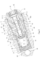
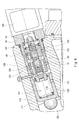
- FIG. 1 It is sectional drawing of the capacity
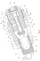
- FIG. 2 is an enlarged view of a main part of FIG. 1 and shows a state when a current between a first set value and a second set value is supplied to the solenoid.
- FIG. 1 shows a capacity adjustment device 1 for a swash pump according to an embodiment of the present invention and a swash plate pump 9 provided with the same.
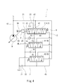
- 4 shows a hydraulic circuit diagram of the capacity adjusting device 1
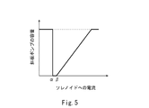
- FIG. 5 shows the performance of the capacity adjusting device 1.
- the swash plate pump 9 includes a casing 91, a rotary shaft 92 extending through the casing 91 from the casing 91, and a swash plate 93 configured to be swingable with respect to the rotary shaft 92.
- the tip of the rotating shaft 92 is connected to the output shaft of a drive device (for example, an engine).
- the capacity adjusting device 1 is disposed on the side of the rotating shaft 92.
- the direction from the rotation shaft 92 toward the capacity adjustment device 1 in the direction orthogonal to the rotation shaft 92 is referred to as the upper direction, and the opposite direction is referred to as the lower direction.
- the direction toward the front is called the front and the opposite direction is called the rear.
- the swash plate 93 swings with respect to the concave arc surface of the swash plate support (not shown), but the swing center X is not on the center line of the rotation shaft 92 but from the center line of the rotation shaft 92. The position is shifted upward.
- the front surface of the swash plate 93 is urged by a swash plate spring 94 in the direction of increasing the capacity of the swash plate pump 9.
- the rear surface of the swash plate 93 slides with a plurality of shoes 96.
- the capacity adjusting device 1 includes a housing 2 incorporated in a casing 91 of the swash plate pump 9.
- the casing 91 of the swash plate pump 9 and the housing 2 of the capacity adjusting device 1 are the same members.
- the housing 2 is provided with a receiving hole 20 that extends straight from the outside toward the upper part of the rear surface of the swash plate 93.
- the center line of the accommodation hole 20 is inclined so as to be away from the center line of the rotation shaft 92 as it goes rearward.
- the center line of the receiving hole 20 may be parallel to the center line of the rotation shaft 92.
- the tilting piston 3 is slidably inserted into the front portion of the accommodation hole 20.
- the tilting piston 3 presses the swash plate 93 via the tilting pin 95. That is, the swash plate spring 94 described above urges the swash plate 93 from the side opposite to the tilting piston 3.
- the tilting pin 95 extends in a direction perpendicular to the swinging direction of the swash plate 93 (in FIG. 2, a direction perpendicular to the paper surface, hereinafter referred to as “left-right direction”).
- the tilt pin 95 is held by the swash plate 93 and slides with the tilt piston 3.
- the tilt pin 95 is held by the tilt piston 3 and may slide with the swash plate 93.
- a sphere can be used instead of the tilting pin 95.
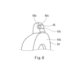
- the swash plate 93 includes an annular main body 93a inserted through the rotation shaft 92 and a lug 93b protruding upward from the main body 93a.
- the lug 93b is provided with a holding hole 93c extending in the left-right direction.
- the tilt pin 95 is press-fitted into the holding hole 93c.
- a step portion 93d is provided at one end of the holding hole 93c, and the tilting pin 95 is press-fitted to a position where it contacts the step portion 93d.
- the tilting pin 95 is prevented from coming off from the holding hole 93c by a set screw (not shown).
- the sleeve 4 is inserted into the rear portion of the accommodation hole 20.
- the sleeve 4 is fixed to the rear portion of the accommodation hole 20 by a screw structure.
- a seal structure using a metal touch or a seal structure using a seal member such as an O-ring may be used.
- a solenoid 6 is disposed behind the sleeve 4, and a spool 5 is disposed in the sleeve 4. The spool 5 is slidably held by the sleeve 4.
- the sleeve 4 forms a control pressure chamber 11 with the tilting piston 3 in the accommodation hole 20. Further, a reaction force chamber 12 is formed in the rear portion of the sleeve 4 (that is, the side opposite to the control pressure chamber 11). The front end portion of the spool 5 is exposed (facing) to the control pressure chamber 11, and the rear end portion of the spool 5 is exposed (facing) to the reaction force chamber 12.
- the tilting piston 3 includes a disk-shaped main wall 31 that is orthogonal to the axial direction of the accommodation hole 20 and a peripheral wall 32 that extends rearward from the peripheral edge of the main wall 31 along the axial direction of the accommodation hole 20. Including. At the rear end of the peripheral wall 32, a plurality of control pressure chambers 11 are not divided into an inner portion surrounded by the peripheral wall 32 and an outer portion around the peripheral wall 32 even when the tilting piston 3 abuts against the sleeve 4. A groove 33 is provided. A plurality of through holes 34 are also provided in the middle of the peripheral wall 32.
- the tilting spring 13 is disposed in the control pressure chamber 11 (more specifically, inside the peripheral wall 32 of the tilting piston 3).
- the tilting spring 13 biases the tilting piston 3 and the spool 5 so as to be separated from each other.
- the tilting spring 13 biases the front end portion of the spool 5 via the spring seat 14.
- the tilt spring 13 may directly bias the front end portion of the spool 5.
- the sleeve 4 is provided with a pump port 41, an output port 43, and a tank port 42 so as to line up from the front to the rear. These ports 41 to 43 extend in the radial direction of the sleeve 4. Further, a communication passage 45 that connects the control pressure chamber 11 to the reaction force chamber 12 is formed in the sleeve 4. The communication path 45 extends in the axial direction of the sleeve 4.
- a supply path 21 that communicates with the pump port 41 and a discharge path 22 that communicates with the tank port 42 are formed.
- the supply path 21 is connected to the discharge line 16 extending from the swash plate pump 9, and constitutes a branch line from the discharge line 16.
- the discharge path 22 is opened inside the casing 91 of the swash plate pump 9, and constitutes a tank line as shown in FIG.
- first control pressure path 23 that communicates with the output port 43 and a second control pressure path 24 that communicates with the control pressure chamber 11 are formed in the housing 2.
- the first control pressure path 23 forms the upstream end of the control pressure line 7 that connects the output port 43 to the control pressure chamber 11 as shown in FIG. 4, and the second control pressure path 24 is downstream of the control pressure line 7. Configure the end.
- two additional function valves 8, a load sensing valve 81 and a cut-off valve 82 are provided in the control pressure line 7.
- only one of the load sensing valve 81 and the cut-off valve 82 may be provided in the control pressure line 7, or both the load sensing valve 81 and the cut-off valve 82 are provided in the control pressure line 7. It does not have to be.
- An additional function valve other than the load sensing valve 81 and the cut-off valve 82 may be provided in the control pressure line 7.
- the load sensing valve 81 is a difference between the maximum load pressure PL of the load pressure of an actuator (not shown) to which a working fluid (for example, working oil) is supplied from the swash plate pump 9 and the discharge pressure of the swash plate pump 9. Operates according to pressure.
- the cut-off valve 82 operates according to the differential pressure between the discharge pressure of the swash plate pump 9 and the spring set pressure.
- a tank line 71 branches off from the control pressure line 7 on the downstream side of the cutoff valve 82, and a throttle 72 is provided in the tank line 71.
- the upstream portion of the load sensing valve 81 and the downstream portion of the cutoff valve 82 in the control pressure line 7 are connected by the first bypass line 73.
- the first bypass line 73 is provided with a check valve 74.
- the check valve 74 allows a flow from the upstream portion of the load sensing valve 81 toward the downstream portion of the cutoff valve 82 and prohibits the reverse flow. Note that the check valve 74 may not be provided in the first bypass line 73.
- the portion between the load sensing valve 81 and the cutoff valve 82 in the control pressure line 7 and the downstream portion of the cutoff valve 82 are connected by the second bypass line 75.
- a diaphragm 76 is provided in the second bypass line 75.
- the solenoid 6 described above is fixed to the rear end of the sleeve 4 by a screw structure.
- the solenoid 6 includes a tubular bolt part 62 protruding into the sleeve 4 and a rod 61 inserted into the bolt part 62.
- the rod 61 presses the rear end portion of the spool 5 from the side opposite to the tilting spring 13. The pressing force of the rod 61 increases as the current supplied to the solenoid 6 increases.
- the front end surface of the bolt part 62 forms the rear wall surface of the reaction force chamber 12.
- the bolt portion 62 functions as a stopper for the spool 5 when no current is supplied to the solenoid 6 (when no current is supplied to the solenoid 6, the rear end portion of the spool 5 abuts against the bolt portion 62).
- the bolt portion 62 is configured so that the inside of the bolt portion 62 is not blocked from the reaction force chamber 12 even when the rear end portion of the spool 5 contacts the bolt portion 62.
- the spool 5 switches whether the output port 43 communicates with one of the pump port 41 and the tank port 42 or is shut off from the pump port 41 and the tank port 43.
- the spool 5 includes a front land portion 51, a first small diameter portion 52, an intermediate land portion 53, a second small diameter portion 54, a rear land portion 55, a spring support portion 56, and a large diameter.
- a portion 57 is included, and these portions 51 to 57 are arranged in this order from the front to the rear.
- the land portions 51, 53, and 55 have the same diameter, and this diameter is larger than the diameter of the small diameter portions 52 and 54.
- the width of the intermediate land portion 53 is substantially equal to the diameter of the output port 43.
- the intermediate land portion 53 may have a tapered end or a notch at the end. Further, on the inner peripheral surface of the sleeve 4, a groove may be formed in the peripheral surface portion including the position where the output port opens.
- the spring support portion 56 is located in the reaction force chamber 12 and has a diameter larger than the diameter of the rear land portion 55.
- the large diameter part 57 has a diameter larger than the diameter of the spring support part 56.
- the large-diameter portion 57 is urged toward the solenoid 6 by the return spring 15 inserted through the spring support portion 56.
- the return spring 15 can be omitted.
- the capacity adjusting device 1 maximizes the capacity of the swash plate pump 9 when the current supplied to the solenoid 6 is smaller than the first set value ⁇ as shown in FIG.
- the capacity of the swash plate pump 9 is made zero when it is between the value ⁇ and the second set value ⁇ , and the capacity of the swash plate pump 9 is increased as the current increases from the second set value ⁇ .
- the rear land portion 55 of the spool 5 is formed with two grooves 55a extending from the front end of the rear land portion 55 to an intermediate position at an interval of 180 degrees.
- the spool 5 communicates the tank port 42 with the reaction force chamber 12 through the groove 55 a.
- the groove 55a functions as a stop.
- the number of grooves 55a may be one, or may be three or more.
- the intermediate land portion 53 moves to a position where the output port 43 is closed.
- the pressure in the control pressure chamber 11 is adjusted by the intermediate land portion 53, and the tilting piston moves to a position where the pressing force of the rod 61 by the solenoid 6 and the biasing force of the tilting spring 13 against the spool 5 are balanced. That is, the displacement volume is adjusted according to the current value supplied to the solenoid 6.
- the manufacturing cost can be reduced.
- the communication passage 45 that communicates the control pressure chamber 11 with the reaction force chamber 12 is formed in the sleeve 4, the spool 5 can be reduced in size. As a result, downsizing of the entire swash plate pump can be realized.
- the tilting piston 3 is advanced most and the capacity of the swash plate pump 9 is minimized. That is, the solenoid 6 can be switched from the fail-safe state to the standby state by supplying a current larger than the first set value ⁇ .
- the upstream portion of the load sensing valve 81 and the downstream portion of the cutoff valve 82 in the control pressure line 7 are connected by the first bypass line 73, so that the load sensing valve 81 and / or Even when the cut-off valve 82 closes the control pressure line 7, it is possible to ensure appropriate responsiveness with respect to capacity adjustment.
- the first control pressure path 23 and the second control pressure path 24 are not necessarily formed in the housing 2, and the output port 43 directly communicates with the control pressure chamber 11 as shown in FIG. You may do it.
- the output port 43 may be connected to the communication path 45.
- an additional function valve 8 is provided in the control pressure line 7 so that the function of capacity adjustment is added.
- the configuration in which the tilting piston 3 presses the swash plate 93 via the tilting pin 95 extending in the direction orthogonal to the swinging direction of the swash plate 93 is also applicable to the hydraulic motor 200 as shown in FIG. It is.
- the hydraulic motor 200 is inclined via a rotation shaft 240, a swash plate 210 configured to be swingable with respect to the rotation shaft 240, and a tilt pin 230 extending in a direction orthogonal to the swinging direction of the swash plate 210.
- a tilting piston 220 that presses the plate 93 is included.
- the tilt pin 230 is held by the swash plate 210 and slides with the tilt piston 220, but the tilt pin 230 is held by the tilt piston 220 and slides with the swash plate 210. Also good.
- the tilting pin when used instead of the ball, the tilting pin is in line contact with the sliding member, so that the wear resistance is higher than when the tilting piston presses the swash plate via the ball. Can be improved.
- an inexpensive method such as press fitting can be used to hold the tilting pin on the holding member. Thereby, compared with the case where a tilting piston presses a swash plate via a ball
- the tilt pin when the tilt pin is used, the radial load acting between the tilt piston and the accommodation hole is reduced as compared with the case where a ball is used. Accordingly, adhesion of the tilting piston to the accommodation hole can be prevented.
- the tilt pin may be a cylindrical member having a circular cross section or an elliptical cylindrical member.
- the shape of the spool 5 is not limited to the shape shown in FIG.
- the pressure in the control pressure chamber 11 is maximum. It may be. In other words, the presence or absence of fail safe can be switched by replacing the spool 5.
Landscapes
- Engineering & Computer Science (AREA)
- Mechanical Engineering (AREA)
- General Engineering & Computer Science (AREA)
- Reciprocating Pumps (AREA)
- Control Of Positive-Displacement Pumps (AREA)
Abstract
Description
本発明は上述した実施形態に限定されるものではなく、本発明の要旨を逸脱しない範囲で種々の変形が可能である。
11 制御圧室
12 反力室
13 傾転スプリング
2 ハウジング
20 収容穴
23 第1制御圧路
24 第2制御圧路
3 傾転ピストン
4 スリーブ
41 ポンプポート
42 タンクポート
43 出力ポート
5 スプール
6 ソレノイド
61 ロッド
7 制御圧ライン
73,75 バイパスライン
74 逆止弁
8 付加機能弁
9 斜板ポンプ
91 ケーシング
93 斜板
95 傾転ピン
Claims (6)
- 斜板ポンプのケーシングに組み込まれた、収容穴を有するハウジングと、
前記収容穴内に摺動可能に挿入され、前記斜板ポンプの斜板を押圧する傾転ピストンと、
前記収容穴内に挿入され、前記傾転ピストンとの間に制御圧室を形成する、ポンプポート、タンクポートおよび出力ポートを有するスリーブと、
前記スリーブに摺動可能に保持された、前記出力ポートを前記ポンプポートと前記タンクポートの一方と連通するか前記ポンプポートおよび前記タンクポートから遮断するかを切り換えるスプールと、
前記制御圧室内に配置され、前記傾転ピストンおよび前記スプールを互いに離間するように付勢する傾転スプリングと、
前記傾転スプリングと反対側から前記スプールを押圧するロッドを含むソレノイドと、を備え、
前記スリーブには、前記制御圧室とは反対側に反力室が形成されているとともに、前記制御圧室を前記反力室と連通する連通路が形成されている、斜板ポンプの容量調整装置。 - 前記ハウジングには、前記出力ポートを前記制御圧室と接続する制御圧ラインの一部を構成する、前記出力ポートと連通する第1制御圧路および前記制御圧室と連通する第2制御圧路が形成されている、請求項1に記載の斜板ポンプの容量調整装置。
- 前記制御圧ラインに設けられた少なくとも1つの付加機能弁と、
前記制御圧ラインにおける前記少なくとも1つの付加機能弁の上流側部分と下流側部分とを接続するバイパスラインと、
前記バイパスラインに設けられた、前記上流側部分から前記下流側部分に向かう流れは許容し、その逆の流れは禁止する逆止弁と、をさらに備える、請求項2に記載の斜板ポンプの容量調整装置。 - 前記斜板は、前記傾転ピストンと反対側から斜板スプリングによって付勢されており、
前記スプールは、前記ソレノイドに電流が供給されていないときに、前記ポンプポートを閉塞するとともに、前記タンクポートを前記反力室と連通するように構成されている、請求項1~3のいずれか一項に記載の斜板ポンプの容量調整装置。 - 前記スプールは、前記ソレノイドに第1設定値と第2設定値の間の電流が供給されているときに、前記ロッドに押圧されて、前記ポンプポートを前記出力ポートと連通するとともに、前記タンクポートを前記反力室から遮断するように構成されている、請求項4に記載の斜板ポンプの容量調整装置。
- 前記傾転ピストンは、前記斜板の揺動方向と直交する方向に延びる傾転ピンを介して前記斜板を押圧する、請求項1~5のいずれか一項に記載の斜板ポンプの容量調整装置。
Priority Applications (4)
| Application Number | Priority Date | Filing Date | Title |
|---|---|---|---|
| DE112016006012.2T DE112016006012T5 (de) | 2015-12-25 | 2016-11-08 | Verschiebungseinstellvorrichtung einer Taumelscheibenpumpe |
| KR1020187020511A KR102045007B1 (ko) | 2015-12-25 | 2016-11-08 | 사판 펌프의 용량 조절 장치 |
| CN201680075627.0A CN108474364B (zh) | 2015-12-25 | 2016-11-08 | 斜盘泵的容量调节装置 |
| US16/061,503 US10914294B2 (en) | 2015-12-25 | 2016-11-08 | Displacement adjusting device of swash plate pump |
Applications Claiming Priority (2)
| Application Number | Priority Date | Filing Date | Title |
|---|---|---|---|
| JP2015-253200 | 2015-12-25 | ||
| JP2015253200A JP6613135B2 (ja) | 2015-12-25 | 2015-12-25 | 斜板ポンプの容量調整装置 |
Publications (1)
| Publication Number | Publication Date |
|---|---|
| WO2017110274A1 true WO2017110274A1 (ja) | 2017-06-29 |
Family
ID=59089305
Family Applications (1)
| Application Number | Title | Priority Date | Filing Date |
|---|---|---|---|
| PCT/JP2016/083084 Ceased WO2017110274A1 (ja) | 2015-12-25 | 2016-11-08 | 斜板ポンプの容量調整装置 |
Country Status (6)
| Country | Link |
|---|---|
| US (1) | US10914294B2 (ja) |
| JP (1) | JP6613135B2 (ja) |
| KR (1) | KR102045007B1 (ja) |
| CN (1) | CN108474364B (ja) |
| DE (1) | DE112016006012T5 (ja) |
| WO (1) | WO2017110274A1 (ja) |
Families Citing this family (13)
| Publication number | Priority date | Publication date | Assignee | Title |
|---|---|---|---|---|
| US10961998B2 (en) * | 2018-03-08 | 2021-03-30 | Hartmann Controls, Inc. | Electro-hydraulic swashplate control arrangement for an axial piston pump |
| DE102018208069A1 (de) | 2018-05-23 | 2019-11-28 | Robert Bosch Gmbh | Axialkolbenmaschine mit Ausnehmung im Bereich des Stelldruckkanals |
| JP7118810B2 (ja) * | 2018-08-27 | 2022-08-16 | ナブテスコ株式会社 | 斜板、軸状部材付き斜板および油圧装置 |
| DE102018214481A1 (de) | 2018-08-28 | 2020-03-05 | Robert Bosch Gmbh | Hydrostatische Verdrängermaschine |
| JP6993950B2 (ja) * | 2018-09-28 | 2022-01-14 | Kyb株式会社 | 液圧回転機 |
| FR3093138B1 (fr) * | 2019-02-25 | 2022-07-15 | Univ Versailles Saint Quentin En Yvelines | Actionneur hydraulique à compensation de surpression |
| DE102020206599A1 (de) * | 2019-06-26 | 2020-12-31 | Robert Bosch Gesellschaft mit beschränkter Haftung | Stellzylinder für eine hydrostatische Axialkolbenmaschine und hydrostatische Axialkolbenmaschine mit einem Stellzylinder |
| DE102020101030B4 (de) * | 2020-01-17 | 2022-11-03 | Hanon Systems | Vorrichtung zum Regeln eines Durchflusses und Verteilen eines Fluids in einem Fluidkreislauf |
| CH717936A1 (de) * | 2020-10-06 | 2022-04-14 | Liebherr Machines Bulle Sa | Axialkolbenmaschine mit Steuerventil. |
| CN112377381A (zh) * | 2020-11-25 | 2021-02-19 | 力源液压(苏州)有限公司 | 电比例柱塞泵及其变量控制装置 |
| CN112302895A (zh) * | 2020-11-25 | 2021-02-02 | 力源液压(苏州)有限公司 | 一种轴向柱塞泵 |
| US12448955B2 (en) * | 2021-02-16 | 2025-10-21 | Parker-Hannifin Corporation | Displacement control for hydraulic pump |
| US12421956B2 (en) * | 2022-12-05 | 2025-09-23 | Hamilton Sundstrand Corporation | Variable displacement pumps with fixed and active displacement control modes |
Citations (3)
| Publication number | Priority date | Publication date | Assignee | Title |
|---|---|---|---|---|
| JP4691299B2 (ja) * | 1999-10-12 | 2011-06-01 | ブルーニンガウス ハイドロマティック ゲゼルシャフト ミット ベシュレンクテル ハフツンク | 斜板ピストンエンジンの調整装置 |
| US20140116242A1 (en) * | 2012-10-31 | 2014-05-01 | Robert Bosch Gmbh | Adjustment apparatus for a hydrostatic piston machine, and hydrostatic piston machine having an adjustment apparatus of this kind |
| JP2015529297A (ja) * | 2012-08-30 | 2015-10-05 | キャタピラー インコーポレイテッドCaterpillar Incorporated | ポンプ排出圧制御のための電子油圧制御の設計 |
Family Cites Families (2)
| Publication number | Priority date | Publication date | Assignee | Title |
|---|---|---|---|---|
| JP5391648B2 (ja) * | 2008-10-28 | 2014-01-15 | 株式会社豊田自動織機 | 可変容量型圧縮機における容量制御機構 |
| WO2014156532A1 (ja) * | 2013-03-27 | 2014-10-02 | カヤバ工業株式会社 | ポンプ吐出流量制御装置 |
-
2015
- 2015-12-25 JP JP2015253200A patent/JP6613135B2/ja active Active
-
2016
- 2016-11-08 WO PCT/JP2016/083084 patent/WO2017110274A1/ja not_active Ceased
- 2016-11-08 DE DE112016006012.2T patent/DE112016006012T5/de active Pending
- 2016-11-08 CN CN201680075627.0A patent/CN108474364B/zh active Active
- 2016-11-08 US US16/061,503 patent/US10914294B2/en active Active
- 2016-11-08 KR KR1020187020511A patent/KR102045007B1/ko active Active
Patent Citations (3)
| Publication number | Priority date | Publication date | Assignee | Title |
|---|---|---|---|---|
| JP4691299B2 (ja) * | 1999-10-12 | 2011-06-01 | ブルーニンガウス ハイドロマティック ゲゼルシャフト ミット ベシュレンクテル ハフツンク | 斜板ピストンエンジンの調整装置 |
| JP2015529297A (ja) * | 2012-08-30 | 2015-10-05 | キャタピラー インコーポレイテッドCaterpillar Incorporated | ポンプ排出圧制御のための電子油圧制御の設計 |
| US20140116242A1 (en) * | 2012-10-31 | 2014-05-01 | Robert Bosch Gmbh | Adjustment apparatus for a hydrostatic piston machine, and hydrostatic piston machine having an adjustment apparatus of this kind |
Also Published As
| Publication number | Publication date |
|---|---|
| JP2017115749A (ja) | 2017-06-29 |
| CN108474364B (zh) | 2019-11-12 |
| JP6613135B2 (ja) | 2019-11-27 |
| DE112016006012T5 (de) | 2018-09-27 |
| KR102045007B1 (ko) | 2019-11-14 |
| KR20180095042A (ko) | 2018-08-24 |
| US10914294B2 (en) | 2021-02-09 |
| CN108474364A (zh) | 2018-08-31 |
| US20200263675A1 (en) | 2020-08-20 |
Similar Documents
| Publication | Publication Date | Title |
|---|---|---|
| JP6613135B2 (ja) | 斜板ポンプの容量調整装置 | |
| US9670926B2 (en) | Variable displacement pump | |
| CN104564215B (zh) | 内燃机的油泵和油泵的溢流压控制装置 | |
| JP4146312B2 (ja) | 可変容量形ポンプ | |
| JP4602335B2 (ja) | 圧力供給弁 | |
| JP2011163459A (ja) | 建設機械の油圧制御弁 | |
| US20180023564A1 (en) | Variable displacement pump | |
| CN105143669B (zh) | 泵排出流量控制装置 | |
| WO2019216193A1 (ja) | 電磁流量制御弁 | |
| JP6075866B2 (ja) | ポンプ制御装置 | |
| JP3820273B2 (ja) | 油圧ポンプの流量制御弁 | |
| WO2016084804A1 (ja) | 可変容量型ベーンポンプ | |
| EP3037667B1 (en) | Vacuum pump mechanism | |
| JP2011140918A (ja) | 可変容量型ベーンポンプ | |
| JP3746386B2 (ja) | 可変容量型ベーンポンプ | |
| JP5998044B2 (ja) | 可変ポンプ | |
| JP6749137B2 (ja) | 液圧回転機械の傾転角制御装置 | |
| JP2009275537A (ja) | 可変容量型ベーンポンプ | |
| JP2007177821A (ja) | 油圧駆動装置 | |
| JP6031310B2 (ja) | 可変容量型ベーンポンプ | |
| JP2005315349A (ja) | 制御弁装置 | |
| JP2008534887A (ja) | 方向制御弁および方向制御弁を備えた制御装置 | |
| JP2017020562A (ja) | リリーフバルブ | |
| KR20200091813A (ko) | 유량 제어 밸브 및 작업 기계 | |
| US20190376534A1 (en) | Electromagnetic pressure reducing valve and fluid pressure control device including electromagnetic pressure reducing valve |
Legal Events
| Date | Code | Title | Description |
|---|---|---|---|
| 121 | Ep: the epo has been informed by wipo that ep was designated in this application |
Ref document number: 16878172 Country of ref document: EP Kind code of ref document: A1 |
|
| WWE | Wipo information: entry into national phase |
Ref document number: 112016006012 Country of ref document: DE |
|
| ENP | Entry into the national phase |
Ref document number: 20187020511 Country of ref document: KR Kind code of ref document: A |
|
| WWE | Wipo information: entry into national phase |
Ref document number: 1020187020511 Country of ref document: KR |
|
| 122 | Ep: pct application non-entry in european phase |
Ref document number: 16878172 Country of ref document: EP Kind code of ref document: A1 |