WO2017110189A1 - エンジンの制御装置 - Google Patents
エンジンの制御装置 Download PDFInfo
- Publication number
- WO2017110189A1 WO2017110189A1 PCT/JP2016/078579 JP2016078579W WO2017110189A1 WO 2017110189 A1 WO2017110189 A1 WO 2017110189A1 JP 2016078579 W JP2016078579 W JP 2016078579W WO 2017110189 A1 WO2017110189 A1 WO 2017110189A1
- Authority
- WO
- WIPO (PCT)
- Prior art keywords
- engine
- exhaust
- valve
- passage
- intake
- Prior art date
- Legal status (The legal status is an assumption and is not a legal conclusion. Google has not performed a legal analysis and makes no representation as to the accuracy of the status listed.)
- Ceased
Links
Images



Classifications
-
- F—MECHANICAL ENGINEERING; LIGHTING; HEATING; WEAPONS; BLASTING
- F02—COMBUSTION ENGINES; HOT-GAS OR COMBUSTION-PRODUCT ENGINE PLANTS
- F02B—INTERNAL-COMBUSTION PISTON ENGINES; COMBUSTION ENGINES IN GENERAL
- F02B37/00—Engines characterised by provision of pumps driven at least for part of the time by exhaust
-
- F—MECHANICAL ENGINEERING; LIGHTING; HEATING; WEAPONS; BLASTING
- F02—COMBUSTION ENGINES; HOT-GAS OR COMBUSTION-PRODUCT ENGINE PLANTS
- F02B—INTERNAL-COMBUSTION PISTON ENGINES; COMBUSTION ENGINES IN GENERAL
- F02B37/00—Engines characterised by provision of pumps driven at least for part of the time by exhaust
- F02B37/04—Engines with exhaust drive and other drive of pumps, e.g. with exhaust-driven pump and mechanically-driven second pump
-
- F—MECHANICAL ENGINEERING; LIGHTING; HEATING; WEAPONS; BLASTING
- F02—COMBUSTION ENGINES; HOT-GAS OR COMBUSTION-PRODUCT ENGINE PLANTS
- F02B—INTERNAL-COMBUSTION PISTON ENGINES; COMBUSTION ENGINES IN GENERAL
- F02B37/00—Engines characterised by provision of pumps driven at least for part of the time by exhaust
- F02B37/12—Control of the pumps
-
- F—MECHANICAL ENGINEERING; LIGHTING; HEATING; WEAPONS; BLASTING
- F02—COMBUSTION ENGINES; HOT-GAS OR COMBUSTION-PRODUCT ENGINE PLANTS
- F02B—INTERNAL-COMBUSTION PISTON ENGINES; COMBUSTION ENGINES IN GENERAL
- F02B37/00—Engines characterised by provision of pumps driven at least for part of the time by exhaust
- F02B37/12—Control of the pumps
- F02B37/18—Control of the pumps by bypassing exhaust from the inlet to the outlet of turbine or to the atmosphere
-
- F—MECHANICAL ENGINEERING; LIGHTING; HEATING; WEAPONS; BLASTING
- F02—COMBUSTION ENGINES; HOT-GAS OR COMBUSTION-PRODUCT ENGINE PLANTS
- F02D—CONTROLLING COMBUSTION ENGINES
- F02D23/00—Controlling engines characterised by their being supercharged
-
- Y—GENERAL TAGGING OF NEW TECHNOLOGICAL DEVELOPMENTS; GENERAL TAGGING OF CROSS-SECTIONAL TECHNOLOGIES SPANNING OVER SEVERAL SECTIONS OF THE IPC; TECHNICAL SUBJECTS COVERED BY FORMER USPC CROSS-REFERENCE ART COLLECTIONS [XRACs] AND DIGESTS
- Y02—TECHNOLOGIES OR APPLICATIONS FOR MITIGATION OR ADAPTATION AGAINST CLIMATE CHANGE
- Y02T—CLIMATE CHANGE MITIGATION TECHNOLOGIES RELATED TO TRANSPORTATION
- Y02T10/00—Road transport of goods or passengers
- Y02T10/10—Internal combustion engine [ICE] based vehicles
- Y02T10/12—Improving ICE efficiencies
Definitions
- the present invention relates to an engine control device including an electric supercharger that supercharges intake air with an electric motor and a mechanical supercharger that recovers exhaust gas energy by a turbine and supercharges intake air.
- Engines equipped with a mechanical supercharger that supercharges intake air introduced into the combustion chamber using the energy of exhaust gas are widely used.
- This type of mechanical supercharger also called a turbocharger, is configured by arranging a compressor in the middle of the intake passage of the engine, placing a turbine in the middle of the exhaust passage, and rotating the turbine with exhaust gas flowing through the exhaust passage.
- the compressor is operated to increase the amount of intake air into the combustion chamber to improve the engine torque.
- the mechanical supercharger that uses the energy of exhaust gas employs a waste gate valve that adjusts the amount of inflow into the turbine by diverting a part of the exhaust gas.
- the supercharging pressure of intake air can be controlled by adjusting the amount of exhaust gas passing through the turbine with a waste gate valve.
- waste gate valves have been controlled by pneumatic actuators that use supercharging pressure as a power source, but recently, electronically controlled waste gate valves that are controlled to open and close by an electric motor have also been adopted. By making the waste gate valve electrically controlled, it can be driven even when the supercharging pressure is low, and more precise control is possible.
- one of the cylinders corresponds to a valve overlap period in which the intake valve and the exhaust valve are simultaneously open.
- the intake valve and the exhaust valve are open at the same time, so if the exhaust gas flows backward to the intake passage side and the engine is restarted in that state, the intake air required for combustion Oxygen may be insufficient. For this reason, there is a demand for removing exhaust gas that has flowed back and keeping the startability at a high temperature always high.
- the present invention has a first object of improving engine startability when the engine is cold, particularly when the outside air temperature is low, and an engine in which backflowed exhaust gas has a great influence on engine startability.
- the second problem is to improve the startability of the engine during the warm condition.
- the present invention provides a mechanical turbocharger including a mechanical compressor that is disposed in an intake passage and supercharges intake air that is introduced into a combustion chamber, and an exhaust turbine that is disposed in an exhaust passage.
- An electric bypass compressor that opens and closes an exhaust bypass passage that connects an upstream side and a downstream side of the exhaust turbine in the exhaust passage; and an electric compressor that is disposed in the intake passage and supercharges intake air into the combustion chamber
- An engine control device that drives the electric supercharger at the start of the engine and closes the exhaust bypass valve is employed.
- the driving of the electric supercharger and the setting of the exhaust bypass valve to the closed state at the time of engine start are performed until the engine start is completed.
- the electric supercharger is driven and the exhaust bypass valve is set to the closed state, particularly when the engine is cold or when the outside air temperature is a predetermined temperature or less. high.
- an intake valve that opens and closes the opening of the intake passage to the combustion chamber
- an exhaust valve that opens and closes the opening of the exhaust passage to the combustion chamber. Both of the intake valve and the exhaust valve are open. Even when the valve overlap period, which is the state that has been set, is set, the effect of improving startability can be exhibited.
- the present invention provides a machine including a mechanical compressor that is disposed in an intake passage and supercharges intake air that is introduced into a combustion chamber, and an exhaust turbine that is disposed in an exhaust passage.
- a turbocharger an exhaust bypass valve that opens and closes an exhaust bypass passage connecting the upstream side and the downstream side of the exhaust turbine in the exhaust passage, and an electric motor that is disposed in the intake passage and supercharges intake air to the combustion chamber
- an electric supercharger equipped with a compressor and when starting the engine, the exhaust bypass valve is opened when the engine is warm, and the exhaust bypass valve is opened when the engine is cold
- the engine control device is used to close the engine.
- An intake valve that opens and closes an opening of the intake passage to the combustion chamber; and an exhaust valve that opens and closes an opening of the exhaust passage to the combustion chamber. Both of the intake valve and the exhaust valve are opened.
- the effect of improving startability is particularly high when the valve overlap period is set.
- the driving of the electric supercharger when the engine is warm is preferably performed until the start of the engine is completed.
- the electric supercharger is driven when the engine is started, and the exhaust bypass valve of the exhaust bypass passage that avoids the turbine of the mechanical supercharger is closed. Even when the outside air temperature is low, the charging efficiency of intake air into the combustion chamber can be increased and the engine startability can be improved.
- the exhaust bypass valve of the exhaust bypass passage that avoids the turbine of the mechanical supercharger in the exhaust passage is opened when the engine is started in the warm state.
- the exhaust gas flowing backward can be efficiently discharged to the exhaust passage, and the engine startability can be improved.
- FIG. 1 is a schematic view conceptually showing an engine control device E according to this embodiment.
- the engine 1 of this embodiment is a four-cycle gasoline engine for automobiles.
- the configuration of the engine 1 includes an intake port 3 for sending intake air into a cylinder 2 having a combustion chamber therein, an intake passage 4 leading to the intake port 3, and an exhaust passage 14 drawn from the exhaust port 13. And a fuel injection device for injecting fuel into the intake port 3 or the combustion chamber.
- the intake port 3 and the exhaust port 13 are opened and closed by valves.
- a throttle valve 5 that adjusts a flow area to the intake port 3 toward the upstream side from the intake port 3 that is a connection portion to the combustion chamber, intake air flowing through the intake passage 4
- An air cleaner (not shown) or the like is provided.
- the turbine 12 of the mechanical supercharger 10 a catalyst for removing unburned hydrocarbons (HC) and the like in the exhaust, etc. from the exhaust port 13, which is a connection portion to the combustion chamber, toward the downstream side.
- the exhaust port 13 which is a connection portion to the combustion chamber, toward the downstream side.
- an exhaust purification unit 15 a silencer 16, and the like.
- the mechanical supercharger 10 includes a mechanical compressor 11 that is disposed in the intake passage 4 and supercharges intake air that is introduced into the combustion chamber, and an exhaust turbine 12 that is disposed in the exhaust passage 14. Composed. When the exhaust turbine 12 is rotated by the exhaust gas flowing through the exhaust passage 14, the rotation is transmitted to the mechanical compressor 11 in the intake passage 4. The intake air flowing through the intake passage 4 is supercharged by the rotation of the mechanical compressor 11.
- an exhaust bypass device 40 including an exhaust bypass passage 41 that connects the upstream side and the downstream side of the exhaust turbine 12 in the exhaust passage 14, and an exhaust bypass valve 42 that opens and closes the exhaust bypass passage 41, a so-called waste gate valve.
- a device is provided. If the exhaust bypass valve 42 is opened, a part of the exhaust gas flowing to the exhaust turbine 12 side is diverted to the exhaust bypass passage 41 side, and the exhaust energy applied to the exhaust turbine 12 is reduced.
- the exhaust bypass valve 42 is an electrically controlled wastegate valve that is controlled to open and close by an electric motor.
- an electric supercharger 30 is arranged in the middle of the intake passage 4.
- the electric supercharger 30 includes an electric compressor 32 that is disposed in the intake passage 4 and supercharges intake air into the combustion chamber. When the electric compressor 32 is driven by supplying electric power, the intake air flowing in the intake passage 4 is supercharged.
- the intake passage 4 is provided with an intake bypass passage 33 that connects the upstream side and the downstream side of the electric compressor 32 and an intake bypass valve 34 that opens and closes the intake bypass passage 33.
- Driving power for the exhaust bypass valve 42, the intake bypass valve 34, the electric compressor 32, and the like is supplied from the battery 60.
- the battery 60 that supplies power to the exhaust bypass valve 42, the intake bypass valve 34, the electric compressor 32, and the like is common to the battery that supplies power to other parts of the engine 1 and the vehicle in which the engine 1 is mounted. It is said.
- the battery that supplies driving power to the exhaust bypass valve 42 and the electric compressor 32 can be provided separately from the battery that supplies power to the engine 1 and the entire vehicle.
- a downstream side of the exhaust turbine 12 in the exhaust passage 14 and a midway portion between the mechanical compressor 11 and the second throttle valve 7 in the intake passage 11 are communicated by an exhaust gas recirculation passage 21 constituting the exhaust gas recirculation device 20. .
- a part of the exhaust gas discharged from the combustion chamber returns to the upstream side of the mechanical compressor 11 and the electric compressor 32 in the intake passage 4 as the recirculation gas via the exhaust recirculation passage 21.
- An exhaust gas recirculation valve 22 is provided in the exhaust gas recirculation passage 21. The recirculated gas merges with the intake air in the intake passage 4 in accordance with the pressure state in the intake passage 4 that accompanies the opening and closing of the exhaust gas recirculation valve 22 and the opening and closing of the second throttle valve 7.
- a vehicle equipped with the engine 1 includes an electronic control unit 50 for controlling the engine 1.
- the electronic control unit 50 controls fuel injection by a fuel injection device (not shown) provided in the intake port 3 or the combustion chamber, supercharging pressure control, opening control of the throttle valve 5 and the second throttle valve 7, exhaust gas Commands necessary for control of the gas recirculation device 20 and other control of the engine are performed.
- a fuel injection device not shown
- supercharging pressure control opening control of the throttle valve 5 and the second throttle valve 7
- exhaust gas Commands necessary for control of the gas recirculation device 20 and other control of the engine are performed.
- the electronic control unit 50 also controls the mechanical supercharger control means 51 for controlling the mechanical supercharger 10, the electric supercharger control means 52 for controlling the electric supercharger 30, and the intake bypass valve 34. And an exhaust bypass device control means 54 for controlling the exhaust bypass valve 42 of the exhaust bypass device 40.
- the intake passage 4 is provided with a purge device a that temporarily stores the evaporated fuel generated in the fuel tank in a canister or the like and introduces it into the downstream side of the throttle valve 5. .
- a blow-by gas recirculation device b that recirculates the blow-by gas mainly containing unburned gas leaked into the engine 1 to the intake port 3, opens to the upstream side of the second throttle valve 7, and the pressure in the crankcase A breather device e and the like are provided. These devices are also controlled by the electronic control unit 50.
- a pressure sensor c on the downstream side of the throttle valve 5 a pressure sensor d on the upstream side of the throttle valve 5, and the inside of the intake passage 4 are provided.
- An air flow sensor f for detecting the amount of flowing air is provided.
- the exhaust passage 14 is provided with an exhaust temperature sensor g for detecting the temperature of the exhaust gas as a sensor device that acquires information necessary for controlling the engine 1.
- the engine 1 includes an outside air temperature sensor h that detects the temperature of outside air, a water temperature sensor i that detects the temperature of cooling water that cools the cylinder block and the like, and a rotation speed sensor that detects the rotation speed of the crankshaft of the engine 1. j is provided, and a vehicle equipped with the engine 1 is provided with an accelerator opening sensor k for detecting the amount of depression of the accelerator.
- Information on these various sensors can be acquired by the electronic control unit 50 through a cable.
- step S1 the driver makes a start request for the engine 1 with an ignition starter switch.
- step S2 In response to the starter switch ON operation signal, in step S2, the accelerator opening detected by the accelerator opening sensor k, the coolant temperature detected by the water temperature sensor i, and the outside temperature detected by the outside air temperature sensor h. The temperature and the like are also read into the electronic control unit 50.
- step S3 when it is determined that the engine 1 is in a cold state, that is, when the temperature of the cooling water is lower than a predetermined water temperature (for example, ⁇ 10 ° C.), the process proceeds to step S4 and the exhaust bypass device 40 While the exhaust bypass valve 42 is closed, the process proceeds to step S6, and control for driving the electric compressor 32 of the electric supercharger 30 is performed.
- a predetermined water temperature for example, ⁇ 10 ° C.
- step S3 If it is determined in step S3 that the engine 1 is warm, that is, if the coolant temperature is equal to or higher than a predetermined water temperature (for example, ⁇ 10 ° C.), the process proceeds to step S5 and the exhaust bypass device.
- the exhaust bypass valve 42 of 40 is opened, and the process proceeds to step S6, where control for driving the electric compressor 32 of the electric supercharger 30 is performed.
- step S7 a starter switch ON operation signal is received, and the starter provided in the engine 1 is driven by electric power.
- the starter is driven, the rotational speed of the crankshaft of the engine 1 is detected by the rotational speed sensor j.
- the rotational speed of the crankshaft is read into the electronic control unit 50.
- the electric supercharger 30 When the engine 1 is cold, the electric supercharger 30 is operated to increase the charging efficiency of the intake air into the combustion chamber, so that the piston ring and valve seat when the movement of the piston in the combustion chamber is in the compression stroke Even if intake air leaks from the periphery, the amount of intake air is sufficient, so that an actual compression ratio can be secured so that combustion necessary for starting can be obtained. For this reason, the startability in the cold state can be improved.
- the driving of the electric supercharger 30 and the maintenance of the closed state of the exhaust bypass valve 42 at the time of starting may be performed when the outside air temperature is equal to or lower than a predetermined temperature regardless of the coolant temperature.
- the cooling water temperature condition and the outside air temperature condition may be combined, and for example, the cooling water temperature may be a predetermined water temperature or lower and the outside air temperature may be a predetermined temperature or lower.
- the driving of the electric supercharger 30 and the maintenance of the closed state of the exhaust bypass valve 42 at the start of the engine are particularly effective in improving startability when the engine is cold or when the outside air temperature is low.
- Whether the start of the engine 1 is completed can be determined by the start determination means 55 provided in the electronic control unit 50 based on the fluctuation of the rotational speed of the crankshaft of the engine 1. As shown by reference sign p1 in FIG. 2, when crankshaft rotation speed reaches the complete explosion speed during cranking by driving the starter, the completion of the start (complete explosion) is determined.
- a period t1 in FIG. 2 indicates a period for driving the electric supercharger 30 and maintaining the closed state of the exhaust bypass valve 42, which is performed from when the ignition starter switch in this embodiment is turned on until the start is completed. ing.
- the period for driving the electric supercharger 30 and maintaining the closed state of the exhaust bypass valve 42 is set not only for the period t1 but also for the period that includes t1 and t2. May be.
- the period t2 is set up to the time when the overshoot of the rotational speed at the start ends.
- the valve over is in a state where both the intake valve that opens and closes the opening of the intake passage 4 to the combustion chamber and the exhaust valve that opens and closes the opening of the exhaust passage 14 to the combustion chamber are opened.
- a lap period is set.
- the closed state of the exhaust bypass valve 42 is maintained at least until the start of the engine is completed, and the exhaust bypass valve 42 is opened after the start of the engine is completed (see step S11 and step S12).
- the switching of the exhaust bypass valve 42 from the closed state to the open state can be performed simultaneously with the stop of the drive of the electric supercharger 30 or after the stop of the drive.
- exhaust pump loss and residual combustion gas can be reduced at an early stage by opening the exhaust bypass valve 42 and lowering the exhaust port pressure.
- the setting of the exhaust bypass valve 42 to the open state may be a period t4 in FIG. 2 in which the rotation of the engine 1 is stabilized and the temperature raising control of the exhaust purification unit 15 is started, or immediately before the overshoot before that. It is good also as a period which combined t3 and t4 including period t3. Further, when the driving of the electric supercharger 30 is completed in the period t1, the closed state of the exhaust bypass valve 42 may be a period in which the periods t2, t3, and t4 are combined.
- the exhaust bypass device 40 that is, the waste gate valve device is electrically controlled, so that it can be driven even when the supercharging pressure is low, and more precise control is possible.
- the exhaust bypass device 40 may be controlled by a pneumatic actuator, the effect is reduced because the waste gate valve is operated after the pressure is generated. At this time, it is desirable to use a negative pressure type using a vacuum pump.
- the temperature of the cooling water that cools the cylinder block and the like of the engine 1 is used. You may use the temperature of the oil, the temperature of the member which comprises the cylinder block of the engine 1, etc.
- the main configuration of the engine 1 in the second embodiment is the same as that of the first embodiment described above corresponding to FIG.
- the control at the time of starting of the engine 1 in the second embodiment will be described based on the graph of FIG. 2, the flowchart of FIG.
- step S21 the driver makes a start request for the engine 1 with an ignition starter switch.
- the accelerator opening detected by the accelerator opening sensor k, the coolant temperature detected by the water temperature sensor i, and the like are read into the electronic control unit 50 in step S22.
- the engine 1 includes an outside air temperature sensor h that detects the temperature of the outside air
- the information on the outside air temperature is read into the electronic control unit 50 together with each of the above information, and the following temperature and cold states are set. It may be used for determination and other control.
- step S23 If it is determined in step S23 that the engine 1 is in a warm state, that is, if the coolant temperature is equal to or higher than a predetermined water temperature (for example, 60 ° C.) that is a reference value, the process proceeds to step S24, and the exhaust bypass is performed. Control for opening the exhaust bypass valve 42 of the device 40 is performed.
- a predetermined water temperature for example, 60 ° C.
- the start of the engine 1 in the warm state for example, a situation of restart from an idling stop, a case where the vehicle is stopped and the engine is stopped, and then immediately restarted to start are considered.
- step S25 when it is determined that the engine 1 is in a cold state at the start, that is, when the coolant temperature is lower than a predetermined water temperature (for example, 60 ° C.) that is a reference value, the process proceeds to step S25, and the exhaust gas is exhausted. Control for closing the exhaust bypass valve 42 of the bypass device 40 is performed.
- step S26 the electric compressor 32 of the electric supercharger 30 is driven, and the supercharged intake air is introduced into the combustion chamber.
- step S27 in response to the starter switch ON operation signal, the starter provided in the engine 1 is driven by electric power.
- the rotational speed of the crankshaft of the engine 1 is detected by the rotational speed sensor j.
- the rotational speed of the crankshaft is read into the electronic control unit 50.
- the valve over is in a state where both the intake valve that opens and closes the opening of the intake passage 4 to the combustion chamber and the exhaust valve that opens and closes the opening of the exhaust passage 14 to the combustion chamber are opened.
- a lap period is set.
- the exhaust bypass valve 42 is opened when the engine temperature is high, the influence of the back-flowing exhaust gas on the engine startability is suppressed, so that an increase in the pressure of the exhaust port 13 is suppressed.
- the exhaust gas flowing backward from the exhaust passage 14 toward the combustion chamber or the intake passage 4 can be quickly discharged toward the exhaust passage 14. For this reason, the intake air is smoothly introduced into the fuel chamber, and the startability of the engine 1 is improved.
- the exhaust gas flowing backward to the combustion chamber or the intake passage 4 side can be discharged more rapidly toward the exhaust passage 14. For this reason, the startability in the warm state can be improved.
- Step S28, Step S29, and Step S30 it is desirable that driving of the electric supercharger 30 at the start of the engine 1 is performed at least until the start of the engine is completed in both the warm state and the cold state.
- the starter is stopped, and at the same time, the driving of the electric supercharger 30 is stopped to reduce power consumption (see Step S28, Step S29, and Step S30). ).
- Whether the start of the engine 1 is completed can be determined by the start determination means 55 provided in the electronic control unit 50 based on the fluctuation of the rotational speed of the crankshaft of the engine 1. As shown by reference sign p1 in FIG. 2, when crankshaft rotation speed reaches the complete explosion speed during cranking by driving the starter, the completion of the start (complete explosion) is determined.
- the period for driving the electric supercharger 30 and maintaining the open state of the exhaust bypass valve 42 is not limited to the period t1, for example, t1 and t2. You may set to the period which united.
- the period t2 is set up to the time when the overshoot of the rotational speed at the start ends.
- the open state of the exhaust bypass valve 42 at the start in the warm state is maintained at least until the start of the engine is completed, but is controlled so as to be open when the exhaust bypass valve 42 is closed. (Refer to step S31 and step S32). After the start of the engine is completed (see step S33), the exhaust bypass valve 42 is selected between an open state and a closed state by normal operation control.
- a period t1 in FIG. 2 is a period for driving the electric supercharger 30 and maintaining the closed state of the exhaust bypass valve 42, which is performed from the ON operation of the ignition starter switch in the cold state to the completion of the start. It can also be.
- the period of driving the electric supercharger 30 and maintaining the closed state of the exhaust bypass valve 42 is not limited to the period of t1, for example, t1 and t2. It may be set to a combined period.
- the period t2 is set up to the time when the overshoot of the rotational speed at the start ends.
- the closed state of the exhaust bypass valve 42 at the start in the cold state is maintained at least until the start of the engine is completed, but the exhaust bypass valve 42 is opened after the start of the engine is completed.
- the switching of the exhaust bypass valve 42 from the closed state to the open state can be performed simultaneously with the stop of the drive of the electric supercharger 30 or after the stop of the drive.
- exhaust pump loss and residual combustion gas can be reduced at an early stage by opening the exhaust bypass valve 42 and lowering the exhaust port pressure.
- the setting of the exhaust bypass valve 42 to the open state may be a period t4 in FIG. 2 in which the rotation of the engine 1 is stabilized and the temperature raising control of the exhaust purification unit 15 is started, or immediately before the overshoot before that. It is good also as a period which combined t3 and t4 including period t3. Further, when the driving of the electric supercharger 30 is finished in the period t1, the open state of the exhaust bypass valve 42 may be a period in which the periods t2, t3, and t4 are combined.
- the exhaust bypass device 40 that is, the waste gate valve device is electrically controlled, so that it can be driven even when the supercharging pressure is low, and more precise control is possible.
- the exhaust bypass device 40 may be controlled by a pneumatic actuator, the effect is reduced because the waste gate valve is operated after the pressure is generated. At this time, it is desirable to use a negative pressure type using a vacuum pump.
- the temperature of the cooling water for cooling the cylinder block or the like of the engine 1 is used to determine whether the engine 1 is warm or cold. For example, you may use the temperature of the lubricating oil of the engine 1, the temperature of the member which comprises the cylinder block of the engine 1, etc.
- the engine 1 of each of these embodiments is a four-cycle gasoline engine for automobiles, it is not limited to this embodiment, and the present invention can be applied to other types of gasoline engines as well as diesel engines.
Landscapes
- Engineering & Computer Science (AREA)
- Chemical & Material Sciences (AREA)
- Combustion & Propulsion (AREA)
- Mechanical Engineering (AREA)
- General Engineering & Computer Science (AREA)
- Supercharger (AREA)
Abstract
吸気通路(4)に配置され燃焼室へ導入される吸気を過給する機械式コンプレッサ(11)と排気通路(14)に配置される排気タービン(12)とを備えた機械式過給機(10)と、排気通路(14)における排気タービン(12)の上流側と下流側とを接続する排気バイパス通路(41)を開閉する排気バイパスバルブ(42)と、吸気通路(4)に配置され燃焼室への吸気を過給する電動式コンプレッサ(32)を備えた電動式過給機(30)とを備え、エンジンの始動時に電動式過給機(30)を駆動するとともに排気バイパスバルブ(42)を閉状態とするエンジンの制御装置とした。
Description
電動機で吸気を過給する電動式過給機と、排気ガスのエネルギをタービンで回収して吸気を過給する機械式過給機を備えるエンジンの制御装置に関する。
排気ガスのエネルギを利用して、燃焼室に導入される吸気を過給する機械式過給機を備えたエンジンが広く採用されている。
この種の機械式過給機はターボチャージャとも呼ばれ、エンジンの吸気通路の途中にコンプレッサを配置し、排気通路の途中にタービンを配置し、排気通路を流れる排気ガスでタービンを回転させることによりコンプレッサを作動させ、燃焼室への吸入空気量を増大させて、エンジンのトルクの向上を図っている。
また、近年は、排気ガスのエネルギを利用した過給機以外にも、コンプレッサを電動機で駆動するようにした電動式過給機が種々提案されている。電動式過給機は、エンジンの運転状態によらず、電力を供給することで任意に過給が出来るという利点がある(例えば、下記特許文献1参照)。
また、排気ガスのエネルギを利用する機械式過給機は、排気ガスの一部を分流させることにより、タービンへの流入量を調節するウェイストゲートバルブが採用される。タービンを通過する排気ガスの量をウェイストゲートバルブで調整することで、吸気の過給圧を制御することができる。
従来のウェイストゲートバルブは、過給圧を動力源とした空圧式アクチュエータにより制御されていたが、近年は、電動機で開閉制御するようにした電制式ウェイストゲートバルブも採用されている。ウェイストゲートバルブを電制式とすることで、過給圧が低い場合でも駆動でき、より緻密な制御が可能となっている。
ところで、一般にエンジンの冷態始動時において、特に外気温が低いと、エンジンやトランスミッションの潤滑油や作動油の粘度が増大し、スタータでクランクを回すための抵抗が増大する。このため、クランキング速度が低下することとなる。
また、外気温が低い場合、バッテリの放電能力が低下するため、スタータへの供給電力が減少し、クランキング速度が低下する。クランキング速度が低下すると、圧縮行程の時間が延びるため、ピストンリングやバルブシートからの吸気漏れ量が増大し、実圧縮比が低下するという問題がある。また、実圧縮比が低下すると、圧縮上死点付近における筒内ガス圧力と筒内ガス温度が低下するので、始動に必要な燃焼が得られないという問題もある。
また、エンジンが温態時である場合、例えば、アイドリングストップ等でエンジンが停止した際に、いずれかの気筒が、吸気バルブと排気バルブとが同時に開いているバルブオーバーラップ期間に該当する。バルブオーバーラップ期間中の気筒は、吸気バルブと排気バルブとが同時に開いているので、排気ガスが吸気通路側へ逆流し、その状態でエンジンの再始動を行うと、燃焼に必要な吸気中の酸素が不足する場合がある。このため、逆流した排気ガスを除去し、温態時の始動性を常に高く保ちたいという要請がある。
そこで、この発明は、エンジンの冷態時、特に、外気温が低い場合において、エンジンの始動性を向上することを第一の課題とし、逆流した排気ガスがエンジン始動性に与える影響が大きいエンジンの温態時において、エンジンの始動性を高めることを第二の課題とする。
上記第一の課題を解決するために、この発明は、吸気通路に配置され燃焼室へ導入される吸気を過給する機械式コンプレッサと排気通路に配置される排気タービンとを備えた機械式過給機と、前記排気通路における前記排気タービンの上流側と下流側とを接続する排気バイパス通路を開閉する排気バイパスバルブと、前記吸気通路に配置され燃焼室への吸気を過給する電動式コンプレッサを備えた電動式過給機とを備え、エンジンの始動時に前記電動式過給機を駆動するとともに前記排気バイパスバルブを閉状態とするエンジンの制御装置を採用した。
ここで、エンジンの始動時における前記電動式過給機の駆動及び前記排気バイパスバルブの閉状態への設定はエンジンの始動が完了するまで行われることが望ましい。
また、エンジンの始動時における前記電動式過給機の駆動及び前記排気バイパスバルブの閉状態への設定はエンジンの冷態時又は外気温が所定温度以下の場合に、特に始動性向上の効果が高い。
さらに、前記吸気通路の前記燃焼室への開口を開閉する吸気バルブと、前記排気通路の前記燃焼室への開口を開閉する排気バルブとを備え、前記吸気バルブと前記排気バルブはその両方が開放された状態であるバルブオーバーラップ期間が設定されている場合も、始動性向上の効果を発揮し得る。
これらの各構成において、前記排気バイパスバルブはエンジンの始動が完了した後に開状態とする構成を採用することができる。
また、上記第二の課題を解決するために、この発明は、吸気通路に配置され燃焼室へ導入される吸気を過給する機械式コンプレッサと排気通路に配置される排気タービンとを備えた機械式過給機と、前記排気通路における前記排気タービンの上流側と下流側とを接続する排気バイパス通路を開閉する排気バイパスバルブと、前記吸気通路に配置され燃焼室への吸気を過給する電動式コンプレッサを備えた電動式過給機とを備え、エンジンの始動時に、エンジンが温態時である場合は前記排気バイパスバルブを開状態とし、エンジンが冷態時である場合は前記排気バイパスバルブを閉状態とするエンジンの制御装置を採用した。
ここで、エンジンの始動時に、エンジンが温態時である場合は前記電動式過給機を駆動することが望ましい。
前記吸気通路の前記燃焼室への開口を開閉する吸気バルブと、前記排気通路の前記燃焼室への開口を開閉する排気バルブと、を備え、前記吸気バルブと前記排気バルブはその両方が開放された状態であるバルブオーバーラップ期間が設定されている場合に、始動性向上の効果が特に高い。
エンジンが温態時である場合における前記電動式過給機の駆動はエンジンの始動が完了するまで行われることが望ましい。
また、エンジンが温態時である場合における前記排気バイパスバルブの開状態はエンジンの始動が完了するまで維持される構成を採用することができる。
この発明によれば、エンジンの始動時に電動式過給機を駆動するとともに、機械式過給機のタービンを回避する排気バイパス通路の排気バイパスバルブを閉状態としたので、エンジンの冷態時や外気温が低い場合においても、燃焼室への吸気の充填効率を高め、エンジンの始動性を向上することができる。
また、この発明によれば、温態時におけるエンジンの始動時に、排気通路の機械式過給機のタービンを回避する排気バイパス通路の排気バイパスバルブを開状態としたので、排気通路から吸気通路へ逆流する排気ガスを効率的に排気通路へ排出し、エンジンの始動性を高めることができる。
以下、この発明の第一の実施形態を図1~図3に基づいて説明する。図1は、この実施形態のエンジンの制御装置Eを概念的に示す模式図である。
この実施形態のエンジン1は自動車用4サイクルガソリンエンジンである。エンジン1の構成は、図1に示すように、内部に燃焼室を有する気筒2内に吸気を送り込む吸気ポート3、その吸気ポート3に通じる吸気通路4、排気ポート13から引き出された排気通路14、吸気ポート3又は燃焼室内に燃料を噴射する燃料噴射装置等を備えている。吸気ポート3及び排気ポート13は、それぞれバルブによって開閉される。
この実施形態では4つの気筒を備えた4気筒エンジンを想定しているが、気筒の数に関わらずこの発明を適用可能である。
燃焼室へ通じる吸気通路4には、燃焼室への接続部である吸気ポート3から上流側に向かって、吸気ポート3への流路面積を調節するスロットルバルブ5、吸気通路4を流れる吸気を冷却する吸気冷却装置(インタークーラ)6、機械式過給機(ターボチャージャ)10の機械式コンプレッサ11が、さらに上流側の吸気通路4には、流路面積を調節する第二スロットルバルブ7、エアクリーナ(図示せず)等が設けられる。
排気通路14には、燃焼室への接続部である排気ポート13から下流側に向かって、機械式過給機10のタービン12、排気中の未燃炭化水素(HC)等を除去する触媒等を備えた排気浄化部15、消音器16等が設けられる。
機械式過給機10は、図1に示すように、吸気通路4に配置され燃焼室へ導入される吸気を過給する機械式コンプレッサ11と、排気通路14に配置される排気タービン12とで構成される。排気通路14を流れる排気ガスによって排気タービン12が回転すると、その回転が吸気通路4の機械式コンプレッサ11に伝達される。機械式コンプレッサ11の回転によって、吸気通路4内を流れる吸気に過給が行われる。
また、排気通路14における排気タービン12の上流側と下流側とを接続する排気バイパス通路41と、その排気バイパス通路41を開閉する排気バイパスバルブ42とを備えた排気バイパス装置40、いわゆるウェイストゲートバルブ装置が設けられている。排気バイパスバルブ42を開放すれば、排気タービン12側に流れている排気ガスの一部が排気バイパス通路41側に分流されて、排気タービン12に加わる排気エネルギが低減される。
この実施形態では、排気バイパスバルブ42は電動機で開閉制御される電制式ウェイストゲートバルブとなっている。
さらに、吸気通路4の途中には、電動式過給機30が配置されている。電動式過給機30は、吸気通路4に配置され燃焼室への吸気を過給する電動式コンプレッサ32を備える。電力を供給することにより電動式コンプレッサ32を駆動すると、吸気通路4内を流れる吸気に過給が行われる。
また、吸気通路4には、電動式コンプレッサ32の上流側と下流側とを接続する吸気バイパス通路33と、その吸気バイパス通路33を開閉する吸気バイパスバルブ34が設けられている。
排気バイパスバルブ42や吸気バイパスバルブ34、電動式コンプレッサ32等の駆動電力は、バッテリ60から供給されるようになっている。ここでは、排気バイパスバルブ42や吸気バイパスバルブ34、電動式コンプレッサ32等に電力を供給するバッテリ60を、エンジン1の他の部分やこのエンジン1を搭載する車両全般に電力を供給するバッテリと共通としている。ただし、排気バイパスバルブ42や電動式コンプレッサ32の駆動電力を供給するバッテリは、エンジン1や車両全体に電力を供給するバッテリとは別に設けることもできる。
排気通路14の排気タービン12の下流側と、吸気通路11の機械式コンプレッサ11と第二スロットルバルブ7との中途部分は、排気ガス再循環装置20を構成する排気還流通路21によって連通している。排気還流通路21を介して、燃焼室から排出される排気ガスの一部が、還流ガスとして吸気通路4の機械式コンプレッサ11及び電動式コンプレッサ32の上流側に還流する。この排気還流通路21には排気還流バルブ22が設けられている。排気還流バルブ22の開閉と第二スロットルバルブ7の開閉に伴う吸気通路4内の圧力状態に応じて、還流ガスが吸気通路4内の吸気に合流する。
このエンジン1を搭載する車両は、エンジン1を制御するための電子制御ユニット(Electronic Control Unit)50を備える。
電子制御ユニット50は、吸気ポート3又は燃焼室内に設けた燃料噴射装置(図示せず)による燃料噴射や、過給圧の制御、スロットルバルブ5や第二スロットルバルブ7の開度の制御、排気ガス再循環装置20の制御、その他、エンジンの制御に必要な指令を行う。
また、電子制御ユニット50は、機械式過給機10を制御する機械式過給機制御手段51、電動式過給機30を制御する電動式過給機制御手段52、吸気バイパスバルブ34を制御する吸気バイパス装置制御手段53、排気バイパス装置40の排気バイパスバルブ42を制御する排気バイパス装置制御手段54を備える。
また、図1に示すように、吸気通路4には、燃料タンクで発生した蒸発燃料をキャニスタ等において一時的に蓄え、それをスロットルバルブ5の下流側に導入するパージ装置aが設けられている。また、エンジン1の内部に漏出した未燃焼ガスを主成分とするブローバイガスを、吸気ポート3に還流させるブローバイガス還流装置b、第二スロットルバルブ7の上流側に開口してクランクケース内の圧力を逃がすためのブリーザ装置e等が設けられている。これらの装置も、電子制御ユニット50が制御する。
さらに、吸気通路4には、エンジン1の制御に必要な情報を取得するセンサ装置として、スロットルバルブ5の下流側の圧力センサc、スロットルバルブ5の上流側の圧力センサd、吸気通路4内を流れる空気の量を検出するエアーフローセンサf等が設けられている。
排気通路14には、エンジン1の制御に必要な情報を取得するセンサ装置として、排気ガスの温度を検出する排気温度センサgが設けられている。
また、エンジン1には、外気の温度を検出する外気温センサhと、シリンダブロック等を冷却する冷却水の温度を検出する水温センサi、エンジン1のクランクシャフトの回転速度を検出する回転速度センサjが設けられ、また、エンジン1を搭載する車両には、アクセルの踏み込み量を検出するアクセル開度センサk等が設けられている。
これらの各種センサ類の情報は、ケーブルを通じて電子制御ユニット50が取得できるようになっている。
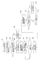
以下、このエンジン1の始動時における制御を、図3のフローチャートに基づいて説明する。
まず、ステップS1において、運転者がイグニッションのスタータスイッチでエンジン1の始動要求を行う。
スタータスイッチのON動作の信号を受けて、ステップS2において、アクセル開度センサkによって検出されるアクセル開度や、水温センサiによって検出される冷却水の水温、外気温センサhによって検出される外気温等も、電子制御ユニット50に読み込まれる。
ステップS3において、エンジン1が冷態時であると判断される場合、すなわち、冷却水の水温が所定水温(例えば、-10℃)未満である場合、ステップS4へ移行し、排気バイパス装置40の排気バイパスバルブ42を閉状態とするとともに、ステップS6へ移行し、電動式過給機30の電動式コンプレッサ32を駆動する制御が行われる。
なお、ステップS3において、エンジン1が温態時であると判断される場合、すなわち、冷却水の水温が所定水温(例えば、-10℃)以上である場合、ステップS5へ移行し、排気バイパス装置40の排気バイパスバルブ42を開状態とするとともに、ステップS6へ移行し、電動式過給機30の電動式コンプレッサ32を駆動する制御が行われる。
ステップS7では、スタータスイッチのON動作の信号を受けて、エンジン1に備えられるスタータが電力により駆動される。スタータが駆動すると、エンジン1のクランクシャフトの回転速度が回転速度センサjによって検出される。クランクシャフトの回転速度は、電子制御ユニット50に読み込まれる。
エンジン1の冷態時に、電動過給機30を作動させて燃焼室への吸気の充填効率を増大させることで、燃焼室内のピストンの動きが圧縮行程中にある場合における、ピストンリングやバルブシート周辺から吸気漏れが発生しても、吸気の充填量が充分であることから、始動に必要な燃焼が得られるような実圧縮比を確保することができる。このため、冷態時における始動性を向上させることができる。
この始動時における電動式過給機30の駆動及び排気バイパスバルブ42の閉状態の維持は、冷却水の水温に係わらず、外気温が所定温度以下の場合に行うようにしてもよい。あるいは、冷却水の水温の条件と外気温の条件とを組み合わせ、例えば、冷却水の水温が所定水温以下で且つ外気温が所定温度以下となる場合に適用するようにしてもよい。エンジンの始動時における電動式過給機30の駆動及び排気バイパスバルブ42の閉状態の維持は、エンジンの冷態時や外気温が低い場合に行われると、特に始動性向上の効果が高い。
ここで、エンジンの始動時における電動式過給機30の駆動は、少なくともエンジンの始動が完了するまで行われることが望ましい。この実施形態では、エンジンの始動が完了した時点でスタータを停止させ、同時に電動式過給機30の駆動を停止し、消費電力量の低減を図っている(ステップS8、ステップS9、ステップS10参照)。
エンジン1の始動が完了したかどうかの判別は、エンジン1のクランクシャフトの回転速度の変動に基づいて、電子制御ユニット50が備える始動判定手段55が行うことができる。図2の符号p1に示すように、スタータの駆動によるクランキング時に、クランクシャフトの回転速度が完爆回転速度に至った場合に、始動の完了(完爆)が判定される。
図2における期間t1は、この実施形態におけるイグニッションのスタータスイッチがON操作から始動の完了までの間に行う、電動式過給機30の駆動及び排気バイパスバルブ42の閉状態の維持の期間を示している。
実施形態の変形例として、電動式過給機30の駆動及び排気バイパスバルブ42の閉状態の維持の期間を、例えば、符号t1の期間だけでなく、符号t1とt2とを合わせた期間に設定してもよい。期間t2は、始動時における回転速度のオーバーシュートが終了する時点まで設定されている。
また、このエンジン1の制御では、吸気通路4の燃焼室への開口を開閉する吸気バルブと、排気通路14の燃焼室への開口を開閉する排気バルブの両方が開放された状態であるバルブオーバーラップ期間が設定されている。
バルブオーバーラップ期間中は、吸気ポート3から燃焼室内に導入された吸気が、そのまま排気ポート13へ流出してしまういわゆる吹き抜け現象が生じやすい。吹き抜け現象が生じると、燃焼室への吸気の充填効率が低下するので、この場合、電動式過給機30の駆動及び排気バイパスバルブ42の閉状態の維持が排気ポートの圧力を高め、始動性向上に特に高い効果を発揮できる。
なお、排気バイパスバルブ42の閉状態は、少なくともエンジンの始動が完了するまで維持され、排気バイパスバルブ42はエンジンの始動が完了した後は開状態とされる(ステップS11、ステップS12参照)。排気バイパスバルブ42の閉状態から開状態への切り替えは、電動式過給機30の駆動の停止と同時に又は駆動の停止後とすることができる。エンジンの始動が完了した後は、排気バイパスバルブ42を開放して排気ポート圧力を下げることで、排気ポンプロスや残留燃焼ガスを早期に低減することができる。
このとき、排気バイパスバルブ42の開状態への設定は、エンジン1の回転が安定し排気浄化部15の昇温制御を開始する図2の期間t4としてもよいし、それ以前のオーバーシュート直後の期間t3を含むt3とt4とを併せた期間としてもよい。また、電動式過給機30の駆動が期間t1で終了している場合は、排気バイパスバルブ42の閉状態を、期間t2、t3とt4とを併せた期間としてもよい。
この実施形態では、排気バイパス装置40、すなわち、ウェイストゲートバルブ装置を電制式とすることで、過給圧が低い場合でも駆動でき、より緻密な制御を可能としているが、ウェイストゲートバルブ装置は、空圧式アクチュエータにより制御してもよいが、ウェイストゲートバルブ作動が圧力発生後となるため、効果は減少する。このとき、バキュームポンプを用いた負圧式とすることが望ましい。
この実施形態では、エンジン1が冷態時であるかどうかを判断するために、エンジン1のシリンダブロック等を冷却する冷却水の温度を用いたが、これに代えて、例えば、エンジン1の潤滑油の温度や、エンジン1のシリンダブロック等を構成する部材の温度を用いてもよい。
つぎに、この発明の第二の実施形態を説明する。
第二の実施形態におけるエンジン1の主たる構成は、図1に対応する前述の第一の実施形態と共通であるので、その説明を省略する。以下、第二の実施形態におけるエンジン1の始動時における制御を、図2のグラフ図、図4のフローチャート等に基づいて説明する。
まず、ステップS21において、運転者がイグニッションのスタータスイッチでエンジン1の始動要求を行う。
スタータスイッチのON動作の信号を受けて、ステップS22において、アクセル開度センサkによって検出されるアクセル開度や、水温センサiによって検出される冷却水の水温等が、電子制御ユニット50に読み込まれる。なお、エンジン1に外気の温度を検出する外気温センサhを備えている場合は、その外気温の情報を、上記の各情報とともに電子制御ユニット50に読み込ませて、以下の温態、冷態の判断やその他の制御に用いてもよい。
ステップS23において、エンジン1が温態時であると判断される場合、すなわち、冷却水の水温が基準値となる所定水温(例えば、60℃)以上である場合、ステップS24へ移行し、排気バイパス装置40の排気バイパスバルブ42を開状態とする制御が行われる。温態時のエンジン1の始動としては、例えば、アイドリングストップからの再始動の状況や、車両を停車させエンジン停止した後、すぐに再始動して発進する場合等が考えられる。
また、始動時に、エンジン1が冷態時であると判断される場合、すなわち、冷却水の水温が基準値となる所定水温(例えば、60℃)未満である場合、ステップS25へ移行し、排気バイパス装置40の排気バイパスバルブ42を閉状態とする制御が行われる。
つづいて、ステップS26では、電動式過給機30の電動式コンプレッサ32の駆動が行われ、燃焼室内に過給状態の吸気が導入される。
ステップS27では、スタータスイッチのON動作の信号を受けて、エンジン1に備えられるスタータが電力により駆動される。スタータが駆動すると、エンジン1のクランクシャフトの回転速度が回転速度センサjによって検出される。クランクシャフトの回転速度は、電子制御ユニット50に読み込まれる。
また、このエンジン1の制御では、吸気通路4の燃焼室への開口を開閉する吸気バルブと、排気通路14の燃焼室への開口を開閉する排気バルブの両方が開放された状態であるバルブオーバーラップ期間が設定されている。
逆流した排気ガスがエンジン始動性に与える影響が大きいエンジンの温態時に排気バイパスバルブ42を開状態とすることで、排気ポート13の圧力上昇を抑制するので、始動の際、エンジン停止時バルブオーバーラップ期間に該当するいずれかの気筒2で、排気通路14から燃焼室内あるいは吸気通路4側へ逆流した排気ガスを、排気通路14へ向かって速やかに排出できる。このため、燃料室内に吸気が円滑に導入され、エンジン1の始動性が向上する。このとき、併せて電動式過給機30を駆動することにより、燃焼室内あるいは吸気通路4側へ逆流した排気ガスを、排気通路14へ向かってさらに速やかに排出できる。このため、温態時における始動性を向上させることができる。
一方、クランキング速度低下による充填効率低下がエンジン始動性に与える影響が大きいエンジンの冷態時に排気バイパスバルブ42を閉状態とすることで、排気ポート13の圧力上昇を促進するので、始動の際、バルブオーバーラップ期間に該当するいずれかの気筒2で、吸気ポート3から燃焼室内に導入された吸気が、そのまま排気ポート13へ流出してしまういわゆる吹き抜け現象を抑制することができ、吸気通路4から燃焼室内に充分な吸気を充填できる。このため、エンジン1の始動性が向上する。このとき、併せて電動式過給機30を駆動することにより、燃焼室内への吸気の充填をさらに高めることができる。このため、冷態時における始動性を向上させることができる。
ここで、エンジン1の始動時における電動式過給機30の駆動は、温態時、冷態時ともに、少なくともエンジンの始動が完了するまで行われることが望ましい。この実施形態では、エンジンの始動が完了した時点でスタータを停止させ、同時に電動式過給機30の駆動を停止し、消費電力量の低減を図っている(ステップS28、ステップS29、ステップS30参照)。
エンジン1の始動が完了したかどうかの判別は、エンジン1のクランクシャフトの回転速度の変動に基づいて、電子制御ユニット50が備える始動判定手段55が行うことができる。図2の符号p1に示すように、スタータの駆動によるクランキング時に、クランクシャフトの回転速度が完爆回転速度に至った場合に、始動の完了(完爆)が判定される。
図2における期間t1は、この実施形態の温態時におけるイグニッションのスタータスイッチがON操作から始動の完了までの間に行う、電動式過給機30の駆動及び排気バイパスバルブ42の開状態の維持の期間を示している。
ただし、この温態時の制御の変形例として、電動式過給機30の駆動及び排気バイパスバルブ42の開状態の維持の期間を、例えば、符号t1の期間だけでなく、符号t1とt2とを合わせた期間に設定してもよい。期間t2は、始動時における回転速度のオーバーシュートが終了する時点まで設定されている。
なお、温態時の始動時における排気バイパスバルブ42の開状態は、少なくともエンジンの始動が完了するまで維持されるが、排気バイパスバルブ42が閉じている場合は開状態になるように制御される(ステップS31、ステップS32参照)。排気バイパスバルブ42はエンジンの始動が完了(ステップS33参照)した後は、通常の運転制御により開状態と閉状態とが選択される。
また、図2における期間t1は、冷態時におけるイグニッションのスタータスイッチがON操作から始動の完了までの間に行う、電動式過給機30の駆動及び排気バイパスバルブ42の閉状態の維持の期間とすることもできる。
ただし、冷態時の制御の変形例として、電動式過給機30の駆動及び排気バイパスバルブ42の閉状態の維持の期間を、例えば、符号t1の期間だけでなく、符号t1とt2とを合わせた期間に設定してもよい。期間t2は、始動時における回転速度のオーバーシュートが終了する時点まで設定されている。
冷態時の始動時における排気バイパスバルブ42の閉状態は、少なくともエンジンの始動が完了するまで維持されるが、排気バイパスバルブ42はエンジンの始動が完了した後は、開状態とされる。排気バイパスバルブ42の閉状態から開状態への切り替えは、電動式過給機30の駆動の停止と同時に又は駆動の停止後とすることができる。エンジンの始動が完了した後は、排気バイパスバルブ42を開放して排気ポート圧力を下げることで、排気ポンプロスや残留燃焼ガスを早期に低減することができる。
このとき、排気バイパスバルブ42の開状態への設定は、エンジン1の回転が安定し排気浄化部15の昇温制御を開始する図2の期間t4としてもよいし、それ以前のオーバーシュート直後の期間t3を含むt3とt4とを併せた期間としてもよい。また、電動式過給機30の駆動が期間t1で終了している場合は、排気バイパスバルブ42の開状態を、期間t2、t3とt4とを併せた期間としてもよい。
この実施形態では、排気バイパス装置40、すなわち、ウェイストゲートバルブ装置を電制式とすることで、過給圧が低い場合でも駆動でき、より緻密な制御を可能としているが、ウェイストゲートバルブ装置は、空圧式アクチュエータにより制御してもよいが、ウェイストゲートバルブ作動が圧力発生後となるため、効果は減少する。このとき、バキュームポンプを用いた負圧式とすることが望ましい。
この実施形態では、エンジン1が温態時であるか冷態時であるかどうかを判断するために、エンジン1のシリンダブロック等を冷却する冷却水の温度を用いたが、これに代えて、例えば、エンジン1の潤滑油の温度や、エンジン1のシリンダブロック等を構成する部材の温度を用いてもよい。
これらの各実施形態のエンジン1は自動車用4サイクルガソリンエンジンとしたが、この実施形態には限定されず、他の形式のガソリンエンジンの他、ディーゼルエンジンでもこの発明を適用できる。
1 エンジン
2 気筒
3 吸気ポート
4 吸気通路
5 スロットルバルブ
6 吸気冷却装置(インタークーラ)
7 第二スロットルバルブ
10 機械式過給機
11 機械式コンプレッサ
12 排気タービン
13 排気ポート
14 排気通路
15 排気浄化部
16 消音器
20 排気ガス再循環装置
21 排気還流通路
22 排気還流バルブ
30 電動式過給機
32 電動式コンプレッサ
33 吸気バイパス通路
34 吸気バイパスバルブ
40 排気バイパス装置
41 排気バイパス通路
42 排気バイパスバルブ
50 電子制御ユニット
51 機械式過給機制御手段
52 電動式過給機制御手段
53 吸気バイパス装置制御手段
54 排気バイパス装置制御手段
55 始動判定手段
2 気筒
3 吸気ポート
4 吸気通路
5 スロットルバルブ
6 吸気冷却装置(インタークーラ)
7 第二スロットルバルブ
10 機械式過給機
11 機械式コンプレッサ
12 排気タービン
13 排気ポート
14 排気通路
15 排気浄化部
16 消音器
20 排気ガス再循環装置
21 排気還流通路
22 排気還流バルブ
30 電動式過給機
32 電動式コンプレッサ
33 吸気バイパス通路
34 吸気バイパスバルブ
40 排気バイパス装置
41 排気バイパス通路
42 排気バイパスバルブ
50 電子制御ユニット
51 機械式過給機制御手段
52 電動式過給機制御手段
53 吸気バイパス装置制御手段
54 排気バイパス装置制御手段
55 始動判定手段
Claims (10)
- 吸気通路に配置され燃焼室へ導入される吸気を過給する機械式コンプレッサと排気通路に配置される排気タービンとを備えた機械式過給機と、
前記排気通路における前記排気タービンの上流側と下流側とを接続する排気バイパス通路を開閉する排気バイパスバルブと、
前記吸気通路に配置され燃焼室への吸気を過給する電動式コンプレッサを備えた電動式過給機と、
を備え、
エンジンの始動時に前記電動式過給機を駆動するとともに前記排気バイパスバルブを閉状態とするエンジンの制御装置。 - エンジンの始動時における前記電動式過給機の駆動及び前記排気バイパスバルブの閉状態への設定はエンジンの始動が完了するまで行われる
請求項1に記載のエンジンの制御装置。 - エンジンの始動時における前記電動式過給機の駆動及び前記排気バイパスバルブの閉状態への設定はエンジンの冷態時又は外気温が所定温度以下の場合に行われる
請求項1又は2に記載のエンジンの制御装置。 - 前記吸気通路の前記燃焼室への開口を開閉する吸気バルブと、
前記排気通路の前記燃焼室への開口を開閉する排気バルブと、
を備え、
前記吸気バルブと前記排気バルブはその両方が開放された状態であるバルブオーバーラップ期間が設定される
請求項1~3の何れか1項に記載のエンジンの制御装置。 - 前記排気バイパスバルブはエンジンの始動が完了した後に開状態とする
請求項1~4の何れか1項に記載のエンジンの制御装置。 - 吸気通路に配置され燃焼室へ導入される吸気を過給する機械式コンプレッサと排気通路に配置される排気タービンとを備えた機械式過給機と、
前記排気通路における前記排気タービンの上流側と下流側とを接続する排気バイパス通路を開閉する排気バイパスバルブと、
前記吸気通路に配置され燃焼室への吸気を過給する電動式コンプレッサを備えた電動式過給機と、
を備え、
エンジンの始動時に、エンジンが温態時である場合は前記排気バイパスバルブを開状態とし、エンジンが冷態時である場合は前記排気バイパスバルブを閉状態とするエンジンの制御装置。 - エンジンの始動時に、エンジンが温態時である場合は前記電動式過給機を駆動する
請求項6に記載のエンジンの制御装置。 - 前記吸気通路の前記燃焼室への開口を開閉する吸気バルブと、
前記排気通路の前記燃焼室への開口を開閉する排気バルブと、
を備え、
前記吸気バルブと前記排気バルブはその両方が開放された状態であるバルブオーバーラップ期間が設定される
請求項7に記載のエンジンの制御装置。 - エンジンが温態時である場合における前記電動式過給機の駆動はエンジンの始動が完了するまで行われる
請求項7又は8に記載のエンジンの制御装置。 - エンジンが温態時である場合における前記排気バイパスバルブの開状態はエンジンの始動が完了するまで維持される
請求項6~9の何れか1項に記載のエンジンの制御装置。
Applications Claiming Priority (4)
| Application Number | Priority Date | Filing Date | Title |
|---|---|---|---|
| JP2015253644A JP6750221B2 (ja) | 2015-12-25 | 2015-12-25 | エンジンの制御装置 |
| JP2015-253640 | 2015-12-25 | ||
| JP2015-253644 | 2015-12-25 | ||
| JP2015253640A JP6750220B2 (ja) | 2015-12-25 | 2015-12-25 | エンジンの制御装置 |
Publications (1)
| Publication Number | Publication Date |
|---|---|
| WO2017110189A1 true WO2017110189A1 (ja) | 2017-06-29 |
Family
ID=59089955
Family Applications (1)
| Application Number | Title | Priority Date | Filing Date |
|---|---|---|---|
| PCT/JP2016/078579 Ceased WO2017110189A1 (ja) | 2015-12-25 | 2016-09-28 | エンジンの制御装置 |
Country Status (1)
| Country | Link |
|---|---|
| WO (1) | WO2017110189A1 (ja) |
Cited By (3)
| Publication number | Priority date | Publication date | Assignee | Title |
|---|---|---|---|---|
| JP2020041516A (ja) * | 2018-09-13 | 2020-03-19 | トヨタ自動車株式会社 | 過給機の制御装置 |
| CN110998085A (zh) * | 2017-07-18 | 2020-04-10 | 标致雪铁龙汽车股份有限公司 | 具有在全功率阶段时保持运行的辅助压缩机的动力总成 |
| US20250163861A1 (en) * | 2023-11-21 | 2025-05-22 | Toyota Jidosha Kabushiki Kaisha | Internal combustion engine |
Citations (5)
| Publication number | Priority date | Publication date | Assignee | Title |
|---|---|---|---|---|
| JP2002021573A (ja) * | 2000-05-11 | 2002-01-23 | Borgwarner Inc | 過給型内燃機関 |
| JP2008069667A (ja) * | 2006-09-12 | 2008-03-27 | Daihatsu Motor Co Ltd | 2サイクルエンジンの始動方法 |
| JP2010180710A (ja) * | 2009-02-03 | 2010-08-19 | Mazda Motor Corp | エンジンの吸気制御方法及びその装置 |
| JP2013238194A (ja) * | 2012-05-16 | 2013-11-28 | Hks Co Ltd | バイフューエルエンジンの過給装置 |
| JP2015025386A (ja) * | 2013-07-25 | 2015-02-05 | 日産自動車株式会社 | 内燃機関の制御装置および制御方法 |
-
2016
- 2016-09-28 WO PCT/JP2016/078579 patent/WO2017110189A1/ja not_active Ceased
Patent Citations (5)
| Publication number | Priority date | Publication date | Assignee | Title |
|---|---|---|---|---|
| JP2002021573A (ja) * | 2000-05-11 | 2002-01-23 | Borgwarner Inc | 過給型内燃機関 |
| JP2008069667A (ja) * | 2006-09-12 | 2008-03-27 | Daihatsu Motor Co Ltd | 2サイクルエンジンの始動方法 |
| JP2010180710A (ja) * | 2009-02-03 | 2010-08-19 | Mazda Motor Corp | エンジンの吸気制御方法及びその装置 |
| JP2013238194A (ja) * | 2012-05-16 | 2013-11-28 | Hks Co Ltd | バイフューエルエンジンの過給装置 |
| JP2015025386A (ja) * | 2013-07-25 | 2015-02-05 | 日産自動車株式会社 | 内燃機関の制御装置および制御方法 |
Cited By (4)
| Publication number | Priority date | Publication date | Assignee | Title |
|---|---|---|---|---|
| CN110998085A (zh) * | 2017-07-18 | 2020-04-10 | 标致雪铁龙汽车股份有限公司 | 具有在全功率阶段时保持运行的辅助压缩机的动力总成 |
| CN110998085B (zh) * | 2017-07-18 | 2022-05-31 | 标致雪铁龙汽车股份有限公司 | 具有在全功率阶段时保持运行的辅助压缩机的动力总成 |
| JP2020041516A (ja) * | 2018-09-13 | 2020-03-19 | トヨタ自動車株式会社 | 過給機の制御装置 |
| US20250163861A1 (en) * | 2023-11-21 | 2025-05-22 | Toyota Jidosha Kabushiki Kaisha | Internal combustion engine |
Similar Documents
| Publication | Publication Date | Title |
|---|---|---|
| JP5370243B2 (ja) | ターボ過給機付きディーゼルエンジンの制御装置 | |
| EP3396132A1 (en) | Engine control device | |
| US9879617B2 (en) | Control apparatus of engine | |
| JP5211997B2 (ja) | ターボ過給機付直噴エンジンの制御方法及びその装置 | |
| US8783015B2 (en) | Shared EGR system and method for a dual-module engine | |
| JP2012036829A (ja) | ブローバイガス還流装置 | |
| JP5167857B2 (ja) | エンジンの自動停止装置 | |
| WO2017110189A1 (ja) | エンジンの制御装置 | |
| JP2008075589A (ja) | 内燃機関のegrガス掃気装置 | |
| JP2013155615A (ja) | 内燃機関の制御装置 | |
| JP6750220B2 (ja) | エンジンの制御装置 | |
| JP6750221B2 (ja) | エンジンの制御装置 | |
| JP2007211710A (ja) | 内燃機関の制御装置 | |
| JP5163515B2 (ja) | 内燃機関の制御装置 | |
| JP6672784B2 (ja) | エンジンの制御装置 | |
| JP2008069667A (ja) | 2サイクルエンジンの始動方法 | |
| JP5397291B2 (ja) | ターボ過給機付きエンジンの始動制御装置 | |
| JP2011214417A (ja) | ディーゼルエンジンの始動制御装置 | |
| JP6613882B2 (ja) | エンジンの制御装置 | |
| US11988164B2 (en) | Start control apparatus of internal combustion engine | |
| JP2014227954A (ja) | エンジンの制御装置 | |
| JP6157147B2 (ja) | ブローバイガス還流装置 | |
| JP2011202591A (ja) | ブローバイガス還流装置 | |
| EP3015686A1 (en) | Engine control device | |
| US20200347813A1 (en) | Engine start control device |
Legal Events
| Date | Code | Title | Description |
|---|---|---|---|
| 121 | Ep: the epo has been informed by wipo that ep was designated in this application |
Ref document number: 16878087 Country of ref document: EP Kind code of ref document: A1 |
|
| NENP | Non-entry into the national phase |
Ref country code: DE |
|
| 122 | Ep: pct application non-entry in european phase |
Ref document number: 16878087 Country of ref document: EP Kind code of ref document: A1 |