EP3396132A1 - Engine control device - Google Patents
Engine control device Download PDFInfo
- Publication number
- EP3396132A1 EP3396132A1 EP16878972.5A EP16878972A EP3396132A1 EP 3396132 A1 EP3396132 A1 EP 3396132A1 EP 16878972 A EP16878972 A EP 16878972A EP 3396132 A1 EP3396132 A1 EP 3396132A1
- Authority
- EP
- European Patent Office
- Prior art keywords
- engine
- charge
- exhaust
- supercharger
- electric
- Prior art date
- Legal status (The legal status is an assumption and is not a legal conclusion. Google has not performed a legal analysis and makes no representation as to the accuracy of the status listed.)
- Pending
Links
Images


Classifications
-
- F—MECHANICAL ENGINEERING; LIGHTING; HEATING; WEAPONS; BLASTING
- F02—COMBUSTION ENGINES; HOT-GAS OR COMBUSTION-PRODUCT ENGINE PLANTS
- F02D—CONTROLLING COMBUSTION ENGINES
- F02D41/00—Electrical control of supply of combustible mixture or its constituents
- F02D41/0002—Controlling intake air
- F02D41/0007—Controlling intake air for control of turbo-charged or super-charged engines
-
- B—PERFORMING OPERATIONS; TRANSPORTING
- B60—VEHICLES IN GENERAL
- B60W—CONJOINT CONTROL OF VEHICLE SUB-UNITS OF DIFFERENT TYPE OR DIFFERENT FUNCTION; CONTROL SYSTEMS SPECIALLY ADAPTED FOR HYBRID VEHICLES; ROAD VEHICLE DRIVE CONTROL SYSTEMS FOR PURPOSES NOT RELATED TO THE CONTROL OF A PARTICULAR SUB-UNIT
- B60W10/00—Conjoint control of vehicle sub-units of different type or different function
- B60W10/04—Conjoint control of vehicle sub-units of different type or different function including control of propulsion units
- B60W10/06—Conjoint control of vehicle sub-units of different type or different function including control of propulsion units including control of combustion engines
-
- B—PERFORMING OPERATIONS; TRANSPORTING
- B60—VEHICLES IN GENERAL
- B60W—CONJOINT CONTROL OF VEHICLE SUB-UNITS OF DIFFERENT TYPE OR DIFFERENT FUNCTION; CONTROL SYSTEMS SPECIALLY ADAPTED FOR HYBRID VEHICLES; ROAD VEHICLE DRIVE CONTROL SYSTEMS FOR PURPOSES NOT RELATED TO THE CONTROL OF A PARTICULAR SUB-UNIT
- B60W10/00—Conjoint control of vehicle sub-units of different type or different function
- B60W10/10—Conjoint control of vehicle sub-units of different type or different function including control of change-speed gearings
-
- B—PERFORMING OPERATIONS; TRANSPORTING
- B60—VEHICLES IN GENERAL
- B60W—CONJOINT CONTROL OF VEHICLE SUB-UNITS OF DIFFERENT TYPE OR DIFFERENT FUNCTION; CONTROL SYSTEMS SPECIALLY ADAPTED FOR HYBRID VEHICLES; ROAD VEHICLE DRIVE CONTROL SYSTEMS FOR PURPOSES NOT RELATED TO THE CONTROL OF A PARTICULAR SUB-UNIT
- B60W20/00—Control systems specially adapted for hybrid vehicles
- B60W20/10—Controlling the power contribution of each of the prime movers to meet required power demand
- B60W20/15—Control strategies specially adapted for achieving a particular effect
- B60W20/19—Control strategies specially adapted for achieving a particular effect for achieving enhanced acceleration
-
- B—PERFORMING OPERATIONS; TRANSPORTING
- B60—VEHICLES IN GENERAL
- B60W—CONJOINT CONTROL OF VEHICLE SUB-UNITS OF DIFFERENT TYPE OR DIFFERENT FUNCTION; CONTROL SYSTEMS SPECIALLY ADAPTED FOR HYBRID VEHICLES; ROAD VEHICLE DRIVE CONTROL SYSTEMS FOR PURPOSES NOT RELATED TO THE CONTROL OF A PARTICULAR SUB-UNIT
- B60W20/00—Control systems specially adapted for hybrid vehicles
- B60W20/30—Control strategies involving selection of transmission gear ratio
-
- B—PERFORMING OPERATIONS; TRANSPORTING
- B60—VEHICLES IN GENERAL
- B60W—CONJOINT CONTROL OF VEHICLE SUB-UNITS OF DIFFERENT TYPE OR DIFFERENT FUNCTION; CONTROL SYSTEMS SPECIALLY ADAPTED FOR HYBRID VEHICLES; ROAD VEHICLE DRIVE CONTROL SYSTEMS FOR PURPOSES NOT RELATED TO THE CONTROL OF A PARTICULAR SUB-UNIT
- B60W30/00—Purposes of road vehicle drive control systems not related to the control of a particular sub-unit, e.g. of systems using conjoint control of vehicle sub-units, or advanced driver assistance systems for ensuring comfort, stability and safety or drive control systems for propelling or retarding the vehicle
- B60W30/18—Propelling the vehicle
- B60W30/188—Controlling power parameters of the driveline, e.g. determining the required power
- B60W30/1882—Controlling power parameters of the driveline, e.g. determining the required power characterised by the working point of the engine, e.g. by using engine output chart
-
- F—MECHANICAL ENGINEERING; LIGHTING; HEATING; WEAPONS; BLASTING
- F02—COMBUSTION ENGINES; HOT-GAS OR COMBUSTION-PRODUCT ENGINE PLANTS
- F02B—INTERNAL-COMBUSTION PISTON ENGINES; COMBUSTION ENGINES IN GENERAL
- F02B37/00—Engines characterised by provision of pumps driven at least for part of the time by exhaust
- F02B37/04—Engines with exhaust drive and other drive of pumps, e.g. with exhaust-driven pump and mechanically-driven second pump
- F02B37/10—Engines with exhaust drive and other drive of pumps, e.g. with exhaust-driven pump and mechanically-driven second pump at least one pump being alternatively or simultaneously driven by exhaust and other drive, e.g. by pressurised fluid from a reservoir or an engine-driven pump
- F02B37/105—Engines with exhaust drive and other drive of pumps, e.g. with exhaust-driven pump and mechanically-driven second pump at least one pump being alternatively or simultaneously driven by exhaust and other drive, e.g. by pressurised fluid from a reservoir or an engine-driven pump exhaust drive and pump being both connected through gearing to engine-driven shaft
-
- F—MECHANICAL ENGINEERING; LIGHTING; HEATING; WEAPONS; BLASTING
- F02—COMBUSTION ENGINES; HOT-GAS OR COMBUSTION-PRODUCT ENGINE PLANTS
- F02B—INTERNAL-COMBUSTION PISTON ENGINES; COMBUSTION ENGINES IN GENERAL
- F02B37/00—Engines characterised by provision of pumps driven at least for part of the time by exhaust
- F02B37/12—Control of the pumps
- F02B37/18—Control of the pumps by bypassing exhaust from the inlet to the outlet of turbine or to the atmosphere
-
- F—MECHANICAL ENGINEERING; LIGHTING; HEATING; WEAPONS; BLASTING
- F02—COMBUSTION ENGINES; HOT-GAS OR COMBUSTION-PRODUCT ENGINE PLANTS
- F02B—INTERNAL-COMBUSTION PISTON ENGINES; COMBUSTION ENGINES IN GENERAL
- F02B39/00—Component parts, details, or accessories relating to, driven charging or scavenging pumps, not provided for in groups F02B33/00 - F02B37/00
- F02B39/02—Drives of pumps; Varying pump drive gear ratio
- F02B39/08—Non-mechanical drives, e.g. fluid drives having variable gear ratio
- F02B39/10—Non-mechanical drives, e.g. fluid drives having variable gear ratio electric
-
- F—MECHANICAL ENGINEERING; LIGHTING; HEATING; WEAPONS; BLASTING
- F02—COMBUSTION ENGINES; HOT-GAS OR COMBUSTION-PRODUCT ENGINE PLANTS
- F02B—INTERNAL-COMBUSTION PISTON ENGINES; COMBUSTION ENGINES IN GENERAL
- F02B41/00—Engines characterised by special means for improving conversion of heat or pressure energy into mechanical power
- F02B41/02—Engines with prolonged expansion
- F02B41/10—Engines with prolonged expansion in exhaust turbines
-
- F—MECHANICAL ENGINEERING; LIGHTING; HEATING; WEAPONS; BLASTING
- F02—COMBUSTION ENGINES; HOT-GAS OR COMBUSTION-PRODUCT ENGINE PLANTS
- F02D—CONTROLLING COMBUSTION ENGINES
- F02D23/00—Controlling engines characterised by their being supercharged
-
- B—PERFORMING OPERATIONS; TRANSPORTING
- B60—VEHICLES IN GENERAL
- B60W—CONJOINT CONTROL OF VEHICLE SUB-UNITS OF DIFFERENT TYPE OR DIFFERENT FUNCTION; CONTROL SYSTEMS SPECIALLY ADAPTED FOR HYBRID VEHICLES; ROAD VEHICLE DRIVE CONTROL SYSTEMS FOR PURPOSES NOT RELATED TO THE CONTROL OF A PARTICULAR SUB-UNIT
- B60W2510/00—Input parameters relating to a particular sub-units
- B60W2510/06—Combustion engines, Gas turbines
- B60W2510/0638—Engine speed
-
- B—PERFORMING OPERATIONS; TRANSPORTING
- B60—VEHICLES IN GENERAL
- B60W—CONJOINT CONTROL OF VEHICLE SUB-UNITS OF DIFFERENT TYPE OR DIFFERENT FUNCTION; CONTROL SYSTEMS SPECIALLY ADAPTED FOR HYBRID VEHICLES; ROAD VEHICLE DRIVE CONTROL SYSTEMS FOR PURPOSES NOT RELATED TO THE CONTROL OF A PARTICULAR SUB-UNIT
- B60W2510/00—Input parameters relating to a particular sub-units
- B60W2510/24—Energy storage means
- B60W2510/242—Energy storage means for electrical energy
- B60W2510/244—Charge state
-
- B—PERFORMING OPERATIONS; TRANSPORTING
- B60—VEHICLES IN GENERAL
- B60W—CONJOINT CONTROL OF VEHICLE SUB-UNITS OF DIFFERENT TYPE OR DIFFERENT FUNCTION; CONTROL SYSTEMS SPECIALLY ADAPTED FOR HYBRID VEHICLES; ROAD VEHICLE DRIVE CONTROL SYSTEMS FOR PURPOSES NOT RELATED TO THE CONTROL OF A PARTICULAR SUB-UNIT
- B60W2540/00—Input parameters relating to occupants
- B60W2540/10—Accelerator pedal position
-
- B—PERFORMING OPERATIONS; TRANSPORTING
- B60—VEHICLES IN GENERAL
- B60W—CONJOINT CONTROL OF VEHICLE SUB-UNITS OF DIFFERENT TYPE OR DIFFERENT FUNCTION; CONTROL SYSTEMS SPECIALLY ADAPTED FOR HYBRID VEHICLES; ROAD VEHICLE DRIVE CONTROL SYSTEMS FOR PURPOSES NOT RELATED TO THE CONTROL OF A PARTICULAR SUB-UNIT
- B60W2710/00—Output or target parameters relating to a particular sub-units
- B60W2710/06—Combustion engines, Gas turbines
- B60W2710/0638—Turbocharger state
-
- B—PERFORMING OPERATIONS; TRANSPORTING
- B60—VEHICLES IN GENERAL
- B60W—CONJOINT CONTROL OF VEHICLE SUB-UNITS OF DIFFERENT TYPE OR DIFFERENT FUNCTION; CONTROL SYSTEMS SPECIALLY ADAPTED FOR HYBRID VEHICLES; ROAD VEHICLE DRIVE CONTROL SYSTEMS FOR PURPOSES NOT RELATED TO THE CONTROL OF A PARTICULAR SUB-UNIT
- B60W2710/00—Output or target parameters relating to a particular sub-units
- B60W2710/08—Electric propulsion units
- B60W2710/083—Torque
-
- F—MECHANICAL ENGINEERING; LIGHTING; HEATING; WEAPONS; BLASTING
- F02—COMBUSTION ENGINES; HOT-GAS OR COMBUSTION-PRODUCT ENGINE PLANTS
- F02B—INTERNAL-COMBUSTION PISTON ENGINES; COMBUSTION ENGINES IN GENERAL
- F02B39/00—Component parts, details, or accessories relating to, driven charging or scavenging pumps, not provided for in groups F02B33/00 - F02B37/00
- F02B39/16—Other safety measures for, or other control of, pumps
- F02B2039/162—Control of pump parameters to improve safety thereof
- F02B2039/168—Control of pump parameters to improve safety thereof the rotational speed of pump or exhaust drive being limited
-
- F—MECHANICAL ENGINEERING; LIGHTING; HEATING; WEAPONS; BLASTING
- F02—COMBUSTION ENGINES; HOT-GAS OR COMBUSTION-PRODUCT ENGINE PLANTS
- F02D—CONTROLLING COMBUSTION ENGINES
- F02D2200/00—Input parameters for engine control
- F02D2200/02—Input parameters for engine control the parameters being related to the engine
- F02D2200/04—Engine intake system parameters
- F02D2200/0406—Intake manifold pressure
-
- F—MECHANICAL ENGINEERING; LIGHTING; HEATING; WEAPONS; BLASTING
- F02—COMBUSTION ENGINES; HOT-GAS OR COMBUSTION-PRODUCT ENGINE PLANTS
- F02D—CONTROLLING COMBUSTION ENGINES
- F02D41/00—Electrical control of supply of combustible mixture or its constituents
- F02D41/02—Circuit arrangements for generating control signals
- F02D41/04—Introducing corrections for particular operating conditions
- F02D41/045—Detection of accelerating or decelerating state
-
- F—MECHANICAL ENGINEERING; LIGHTING; HEATING; WEAPONS; BLASTING
- F02—COMBUSTION ENGINES; HOT-GAS OR COMBUSTION-PRODUCT ENGINE PLANTS
- F02D—CONTROLLING COMBUSTION ENGINES
- F02D41/00—Electrical control of supply of combustible mixture or its constituents
- F02D41/02—Circuit arrangements for generating control signals
- F02D41/18—Circuit arrangements for generating control signals by measuring intake air flow
-
- F—MECHANICAL ENGINEERING; LIGHTING; HEATING; WEAPONS; BLASTING
- F05—INDEXING SCHEMES RELATING TO ENGINES OR PUMPS IN VARIOUS SUBCLASSES OF CLASSES F01-F04
- F05D—INDEXING SCHEME FOR ASPECTS RELATING TO NON-POSITIVE-DISPLACEMENT MACHINES OR ENGINES, GAS-TURBINES OR JET-PROPULSION PLANTS
- F05D2220/00—Application
- F05D2220/40—Application in turbochargers
-
- Y—GENERAL TAGGING OF NEW TECHNOLOGICAL DEVELOPMENTS; GENERAL TAGGING OF CROSS-SECTIONAL TECHNOLOGIES SPANNING OVER SEVERAL SECTIONS OF THE IPC; TECHNICAL SUBJECTS COVERED BY FORMER USPC CROSS-REFERENCE ART COLLECTIONS [XRACs] AND DIGESTS
- Y02—TECHNOLOGIES OR APPLICATIONS FOR MITIGATION OR ADAPTATION AGAINST CLIMATE CHANGE
- Y02T—CLIMATE CHANGE MITIGATION TECHNOLOGIES RELATED TO TRANSPORTATION
- Y02T10/00—Road transport of goods or passengers
- Y02T10/10—Internal combustion engine [ICE] based vehicles
- Y02T10/12—Improving ICE efficiencies
Definitions
- the present invention relates to an engine control device including an electric supercharger for supercharging intake air by means of an electric motor, and a mechanical supercharger for recovering exhaust gas energy with a turbine and supercharging intake air.
- a turbocharger includes a compressor disposed at an intermediate portion of the intake passage of an engine, and a turbine disposed at an intermediate portion of the exhaust passage, and configured such that the compressor is activated due to the rotation of the turbine by exhaust gas flowing through the exhaust passage, to increase the amount of intake air introduced into the combustion chamber(s), thereby increasing the engine torque.
- a mechanical supercharger that utilizes exhaust gas energy includes a wastegate valve for adjusting the amount of exhaust gases into the turbine by partially diverting exhaust gases. By adjusting the amount of exhaust gases that pass through the turbine with the wastegate valve, it is possible to control the supercharging pressure of intake air.
- Older wastegate valves were controlled by pneumatic actuators driven by the supercharging pressure.
- electronically controlled wastegate valves which are selectively opened and closed by an electric motor are also used. By electronically controlling the wastegate valve, it can be controlled even while the supercharging pressure is low, and it can also be more precisely controlled.
- Patent Document 2 discloses a technology for increasing the amount of regenerated energy.
- Patent Document 2 the actuation of a wastegate valve is controlled according to the amount of regenerated energy generated while the vehicle is decelerating.
- the alternator as a dynamo-electric machine regenerates electricity. This opens the wastegate valve, thus reducing the amount of exhaust gases introduced into the turbine, so that it is possible to reduce the pressure of the exhaust gases discharged from the combustion chamber(s) into the exhaust passage.
- the reduced exhaust gas pressure results in reduced pumping loss, which in turn results in reduced engine braking power due to reduced revolving resistance of the engine. This makes it possible to efficiently utilize the kinetic energy of the vehicle for the regeneration of electricity.
- an electric supercharger consumes a considerable amount of electric power, and the amount of electric power which can be supplied to the electric supercharger is limited even if electricity is regenerated. Thus, it is necessary to transfer the supercharging source from the electric supercharger to the mechanical supercharger at some point of time after the start of the electric supercharger.
- An object of the present invention is to allow the electric supercharger and the mechanical supercharger to show maximum performance when transferring the supercharging source for supercharging intake air from the electric supercharger to the mechanical supercharger.
- the present invention provides an engine control device for controlling an engine including a combustion chamber, an intake passage, and an exhaust passage, the engine control device comprising: a dynamo-electric machine configured to generate electric power by rotation of the engine; a secondary battery configured to store the electric power generated by the dynamo-electric machine; an electric supercharger including an electric compressor disposed in the intake passage and configured to supercharge intake air into the combustion chamber by the electric power stored in the secondary battery; and a mechanical supercharger including an exhaust turbine disposed in the exhaust passage and configured to be driven by exhaust gas in the exhaust passage, and a mechanical compressor disposed in the intake passage and configured to supercharge intake air into the combustion chamber.
- the engine control device further comprises: a remaining charge detecting means configured to detect a remaining amount of charge of the secondary battery; and a supercharge control means configured to adjust the ratio between a supercharging pressure by the electric supercharger and a supercharging pressure by the mechanical supercharger according to the remaining amount of charge of the secondary battery.
- the engine may further include an exhaust bypass passage connecting portions of the exhaust passage upstream and downstream of the exhaust turbine, and an exhaust bypass valve configured to selectively open and close the exhaust bypass passage.
- the supercharge control means is configured to control the degree of opening of the exhaust bypass valve according to the remaining amount of charge of the secondary battery.
- the supercharge control means may be configured to determine the degree of opening of the exhaust bypass valve based on the difference between a target supercharging pressure of intake air and the supercharging pressure by the electric supercharger.
- the supercharge control means may be configured to reduce the supercharging pressure by the electric supercharger and increase the supercharging pressure by the mechanical supercharger when the remaining amount of charge of the secondary battery falls below a predetermined amount of charge while the electric supercharger is being activated.
- the engine control device may further comprise an operating state control means configured to control the revolving speed of the engine and a load of the engine with reference to an equi-output curve where an output of the engine does not change, while the ratio between the supercharging pressure by the electric supercharger and the supercharging pressure by the mechanical supercharger is changing.
- the present invention also provides a vehicle comprising the engine control device that includes the above-described operating state control means; an engine configured to be controlled by the engine control device; and a transmission configured to change a speed reduction ratio of the output of the engine.
- the operating state control means is configured to control the speed reduction ratio as the revolving speed of the engine and the load of the engine change along the equi-output curve.
- the ratio between the supercharging pressure by the electric supercharger and the supercharging pressure by the mechanical supercharger are adjusted according to the remaining amount of charge of the secondary battery, it is possible, during supercharging with the electric supercharger, to perform maximum supercharging operation with the electric supercharger within a range in which the secondary battery is not exhausted, by monitoring the remaining amount of charge of the secondary battery, and when the remaining amount of charge of the secondary battery becomes low, it is possible to efficiently transfer the supercharging source from the electric supercharger to the mechanical supercharger.
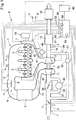
- FIG. 1 schematically shows an entire system E including an engine and a control device thereof embodying the present invention.
- the engine 1 of the embodiment is a four-cycle internal combustion gasoline engine for use in an automobile.
- the engine 1 includes intake ports 3 through which air is fed into respective cylinders 2 defining combustion chambers therein, an intake passage 4 communicating with the intake ports 3, exhaust ports 13, an exhaust passage 14 extending from the exhaust ports 13, and fuel injection devices configured to inject fuel into the intake ports 3 or into the combustion chambers.
- the intake ports 3 and the exhaust ports 13 are opened and closed by respective valves.
- the engine of the embodiment is a four-cylinder engine, i.e., an engine comprising four cylinders, but the present invention is applicable to an engine comprising any number of cylinders.
- the intake passage 4 communicates with the combustion chamber through the intake ports 3. Disposed in the intake passage 4 are, in the upstream direction from the intake ports 3, a first throttle valve 5 configured to adjust the area of the flow passage toward the intake ports 3; an intake air cooling device (intercooler) 6 configured to cool intake air flowing through the intake passage 4; and a mechanical compressor 11 of a mechanical supercharger (turbocharger) 10. Further upstream, a second throttle valve 7 configured to adjust the flow passage area, and an air cleaner (not shown) are disposed in the intake passage 4.
- the exhaust passage 14 communicates with the combustion chambers through the exhaust ports 13.
- an exhaust turbine 12 of the mechanical supercharger 10 Provided in the exhaust passage 14 are, in the downstream direction from the exhaust ports 13, an exhaust turbine 12 of the mechanical supercharger 10; an exhaust purifier 15 including a catalyst for removing e.g., unburned hydrocarbons (HC) in the exhaust; and a muffler 16.
- HC unburned hydrocarbons
- the mechanical compressor 11 of the mechanical supercharger 10, disposed in the intake passage 4 is coaxially coupled to the exhaust turbine 12 of the mechanical supercharger 10, disposed in the exhaust passage 14, such that, when the exhaust turbine 12 is rotated by the exhaust gas flowing through the exhaust passage 14, its rotation is transmitted to the mechanical compressor 11, and the rotating mechanical compressor 11 supercharges the intake air flowing through the intake passage 4 into the combustion chambers.
- the engine 1 further includes an exhaust bypass device 40 (generally known as a "wastegate”) comprising an exhaust bypass passage 41 connecting the portions of the exhaust passage 14 upstream and downstream of the exhaust turbine 12, and an exhaust bypass valve 42 configured to selectively open and close the exhaust bypass passage 41.
- an exhaust bypass device 40 generally known as a "wastegate”
- the exhaust bypass valve 42 When the exhaust bypass valve 42 is open, part of the exhaust gas flowing toward the exhaust turbine 12 is diverted into the exhaust bypass passage 41, and the exhaust energy acing on the exhaust turbine 12 decreases.
- the exhaust bypass valve 42 is an electronically controlled wastegate valve selectively opened and closed by an electric motor.
- An electric supercharger 30 is disposed at an intermediate portion of the intake passage 4.
- the electric supercharger 30 includes an electric compressor 32 disposed at the intake passage 4 and configured to supercharge air into the combustion chambers. In particular, when the electric compressor 32 is energized and driven, the electric compressor 32 supercharges the air flowing through the intake passage 4.
- the intake passage 4 includes an intake bypass passage 33 connecting the upstream side and the downstream side of the electric compressor 32.
- An intake bypass valve 34 is disposed in the intake bypass passage 33 to selectively open and close the intake bypass passage 33.
- Electric power for driving the exhaust bypass valve 42 and the electric compressor 32 is supplied from a battery 60 that also supplies power to other components of the engine 1, as well as to all the other electric components of the vehicle on which the engine 1 is mounted.
- a separate battery i.e., a battery other than the battery 60, may be used to supply electric power for driving the exhaust bypass valve 42 and the electric compressor 32.
- a portion of the exhaust passage 14 downstream of the exhaust turbine 12 is in communication with a portion of the intake passage 11 between the mechanical compressor 11 and the second throttle valve 7 through an exhaust gas recirculation passage 21 which is part of an exhaust gas recirculation device 20.
- the exhaust gas leaving the combustion chamber is partially recirculated, as recirculated gas, through the exhaust gas recirculation passage 21 into the intake passage 4 upstream of the mechanical compressor 11 and the electric compressor 32.
- An exhaust gas recirculation valve 22 is disposed in the exhaust gas recirculation passage 21. The recirculated gas merges with the air in the intake passage 4 depending on the pressure in the intake passage 4 which is determined by the degrees of opening of the exhaust gas recirculation valve 22 and the second throttle valve 7.
- the vehicle V on which the engine 1 is mounted includes an electric control unit (ECU) 50 as a control device for the engine 1.
- ECU electric control unit
- the ECU 50 controls fuel injection by fuel injectors (not shown) at the intake ports 3 or in the combustion chambers; controls supercharging pressure; controls the degrees of opening of the throttle valve 5 and the second throttle valves 7; controls the exhaust gas recirculation device 20; and performs any other necessary control of the engine.
- the ECU 50 includes a supercharge control means 52 configured to control the electric supercharger 30 and the mechanical supercharger 10; an intake bypass device control means 53 configured to control the intake bypass valve 34; and an exhaust bypass device control means 54 configured to control the exhaust bypass valve 42 of the exhaust bypass device 40.
- the supercharge control means 52 simultaneously sends commands to the intake bypass device control means 53 and the exhaust bypass device control means 54 to operate the intake bypass valve 34 and the exhaust bypass valve 42 such that the superchargers 30 and 10 operate in the intended manner.
- the intake passage 4 includes a purge device a configured to temporarily store vaporized fuel in the fuel tank in e.g., a canister, and introduce it into the intake passage 4 downstream of the throttle valve 5.
- the intake passage 4 further includes a blowby gas recirculation device b configured to recirculate blowby gas leaked into the engine 1 which is mainly unburned gas, to the intake ports 3.
- a breather device e opens to the intake passage 4 upstream of the second throttle valve 7 to release the pressure in the crankcase.
- the intake passage 4 is further provided with sensor devices for gathering information necessary to control the engines 1, the sensor devices including pressure sensors c and d for sensing pressures in the intake port 3 downstream and upstream of the throttle valve 5, respectively; and an air flow sensor f for sensing the amount of air flowing through the intake passage 4.
- the exhaust passage 14 includes, as a sensor device for gathering information necessary to control the engine 1, an exhaust gas temperature sensor g for detecting the temperature of the exhaust gas.
- the engine 1 further includes a water temperature sensor i for detecting the temperature of cooling water for cooling e.g., the cylinder block, and a rotational speed sensor i for detecting the rotational speed of the crankshaft of the engine 1.
- the vehicle V on which the engine 1 is mounted includes an accelerator pedal sensor k for detecting the degree of depression of the accelerator pedal, and a vehicle speed sensor l for detecting the vehicle speed.
- the ECU 50 receives the information from these various sensors via cables.
- the ECU 50 controls the throttle valve 5 based on the signal from the accelerator pedal sensor k such that the degree of opening of the throttle valve 5 corresponds to the degree of depression of the accelerator pedal. Based on the information from the vehicle speed sensor l , which is capable of detecting the speed of the vehicle, the ECU 50 is capable of determining whether the vehicle is e.g., accelerating, decelerating, or stopping.
- the engine 1 further includes a dynamo-electric machine 70 configured to generate electricity while the engine 1 is running.
- the dynamo-electric machine 70 as a generator comprises an alternator (and thus is hereinafter referred to as the "alternator 70").
- the alternator 70 is connected to the crankshaft of the engine 1 by e.g., a belt.
- the alternator 70 is electrically connected to the battery 60 (which is a secondary battery capable of storing electric power) via a power supply cable.
- the alternator 70 generates electricity by being driven by the rotation of the crankshaft, and supplies the thus generated electricity to the headlights and other electric components of the vehicle, to devices for controlling the engine 1, and to the battery 60.
- the ECU 50 controls the amount of electricity generated by the alternator 70.
- the ECU 50 further includes a remaining charge detecting means 51 for detecting the remaining amount of charge of the battery 60.
- the supercharge control means 52 is configured to adjust the ratio between the supercharging pressure by the electric supercharger 30 and the supercharging pressure by the mechanical supercharger 10 based on the remaining amount of charge of the battery 60.
- the supercharging pressure of the mechanical supercharger 10 is controlled by adjusting the degree of opening of the exhaust bypass valve 42. That is, when the exhaust bypass valve 42 is closed, the energy the mechanical supercharger 10 recovers from the exhaust gas becomes maximum, so that the supercharging pressure of the mechanical supercharger 10 become maximum. However, when the exhaust bypass valve 42 is closed, the pumping loss during the exhaust stroke increases, and the thermal efficiency falls. Thus, for higher thermal efficiency, it is desired to keep the degree of opening of the exhaust bypass valve 42 as high as possible.
- the superchargers 10 and 30 are controlled to achieve the target supercharging pressure while keeping the degree of opening of the exhaust bypass valve 42 as high as possible, so as to minimize the pumping loss during the exhaust stroke, and improve fuel economy.
- the electric power for driving the electric supercharger 30 is supplied from the battery 60. While the vehicle is being driven by the engine, the alternator 70 generates electricity by being driving by the rotation of the crankshaft of the engine 1, and the battery 60 is charged. While the vehicle is decelerating too, since the alternator 70 regenerates electricity by being driven by the rotation of the crankshaft of the engine 1, the battery 60 is charged. However, since the electric supercharger 30 consumes a large amount of electric power, the battery 60 is incapable of supplying enough power to the electric supercharger 30, even though the alternator 70 regenerates electricity.
- the remaining charge detecting means 51 monitors the remaining amount of charge of the battery 60
- the supercharge control means 52 controls the electric supercharger 30 based on the remaining amount of charge of the battery 60 to gradually slow down and stop the electric supercharger 30 before the battery 60 is exhausted and the electric supercharger 30 stops suddenly.
- the supercharge control means 52 increases the supercharging pressure of the mechanical supercharger 10 by gradually moving the exhaust bypass valve 42 in the closing direction, so as to keep constant the air supply into the combustion chambers, thereby minimizing fluctuations in output.
- the supercharge control means 52 also closes the intake bypass valve 34.
- Step S1 the ECU 50 starts the transient control from the electric supercharger 30 to the mechanical supercharger 10.
- Step S2 the ECU 50 determines whether or not the electric supercharger 30 is operating based on the commands from the supercharge control means 52. If the electric supercharger 30 is not operating, no transient control is necessary, so that the ECU 50 proceeds to Step S14, and the control ends. If the electric supercharger 30 is operating, the ECU 50 proceeds to Step S3.
- the ECU 50 detects the remaining amount of charge of the battery 60. If at Step S4, the remaining amount of charge is not lower than a predetermined amount of charge predetermined for the battery 60, the ECU 50 determines that the operation of the electric supercharger 30 can be continued for a while without problems, and returns to Step S2. If the remaining amount of charge is lower than the predetermined amount of charge, the ECU 50 proceeds to Step S5, and performs specific measures for transferring the supercharging source from the electric supercharger 30 to the mechanical supercharger 10.
- the ECU 50 determines the degree of opening of the exhaust bypass valve 42 based on the remaining amount of charge, specifically based on the difference between the above-mentioned predetermined amount of charge of the battery 60, or a necessary minimum amount of charge of the battery 60, and the current remaining amount of charge of the battery 60.
- the degree of opening of the exhaust bypass valve 42 is decreased correspondingly.
- the degree of opening of the exhaust bypass valve 42 is slightly moved in the closing direction from the fully open position.
- the degree of opening of the exhaust bypass valve 42 at this time is determined based on the charge amount difference obtained by subtracting the current remaining amount of charge from the predetermined amount of charge.
- the relationship between the charge amount difference and the degree of opening of the exhaust bypass valve 42 is predetermined such that, while the charge amount difference is large, the degree of opening of the exhaust bypass valve 42 is small, and while the charge amount difference is small, the degree of opening of the exhaust bypass valve 42 is large.
- the degree of opening of the exhaust bypass valve 42 is further predetermined such that, when the current remaining amount of charge falls below the necessary minimum amount of charge, the intake pressure by the mechanical supercharger 10 alone becomes the target supercharging pressure.
- the ECU 50 determines, at Step S7, a new, reduced supercharging pressure by the electric supercharger 30 such that the target supercharging pressure of the intake air will not change as a result of the increased supercharging pressure by the mechanical supercharger 10.
- the supercharging pressure by the electric supercharger 30 is set at a value equal to the difference between the target supercharging pressure and the supercharging pressure by the mechanical supercharger 10.
- Step S8 the ECU 50 actually reduces the output of the electric supercharger 30 to reduce the supercharging pressure by the electric supercharger 30 to the newly set value.
- the ECU 50 again detects the remaining amount of charge of the battery 60.
- Step S10 if the remaining amount of charge is not lower than the necessary minimum amount of charge, in order to further reduce the supercharging pressure by the electric supercharger 30, the ECU 50 returns to Step S5, and repeats the above-described subroutine. If the remaining amount of charge of the battery 60 is lower than the necessary minimum amount of charge, the ECU 50 moves to Steps S11 and S12 to adjust the degree of opening of the exhaust bypass valve 42 such that the intake pressure by the mechanical supercharger 10 increases to the target supercharging pressure, while deactivating the electric supercharger 30 at Step S13.
- Step S14 the transient control ends.
- Step S21 the ECU 50 starts the transient control from the electric supercharger 30 to the mechanical supercharger 10.
- This control is in many respects similar to the control of Fig. 2 , so that what differs from the control of Fig. 2 is mainly described below
- the ECU 50 determines whether or not the electric supercharger 30 is operating. If the electric supercharger 30 is not operating, no transient control is necessary, so that the ECU 50 proceeds to Step S35, and the control ends. If the electric supercharger 30 is operating, the ECU 50 proceeds to Step S23.
- the ECU 50 detects the remaining amount of charge of the battery 60. If at Step S24, the remaining amount of charge is not lower than a predetermined amount of charge predetermined for the battery 60, the ECU 50 determines that the operation of the electric supercharger 30 can be continued for a while without problems, and returns to Step S22. If the remaining amount of charge is lower than the predetermined amount of charge, the ECU 50 proceeds to Step S25, and performs specific measures for transferring the supercharging source from the electric supercharger 30 to the mechanical supercharger 10.
- the ECU 50 determines the supercharging pressure by the electric supercharger 30 based on the remaining amount of charge, specifically based on the difference between the above-mentioned predetermined amount of charge of the battery 60, or a necessary minimum amount of charge of the battery 60, and the current remaining amount of charge of the battery 60.
- the remaining amount of charge decreases, the output of the electric supercharger 30 is decreased correspondingly.
- the output of the electric supercharger 30 is slightly reduced to slightly reduce the supercharging pressure by the electric supercharger 30.
- the supercharging pressure by the electric supercharger 30, and the corresponding output of the electric supercharger 30 are determined based on the charge amount difference obtained by subtracting the current remaining amount of charge from the predetermined amount of charge.
- the relationship between the charge amount difference and supercharging pressure by the electric supercharger 30 is predetermined such that, while the charge amount difference is large (i.e., the remaining amount of charge is substantially lower than the predetermined amount of charge), the supercharging pressure by the electric supercharger 30 is small, and while the charge amount difference is small (i.e., the remaining amount of charge is not substantially lower than the predetermined amount of charge), the supercharging pressure by the electric supercharger 30 is large.
- the ECU 50 is further configured to reduce the supercharging pressure by the electric supercharger 30 to zero, i.e., deactivate the electric supercharger 30, when the remaining amount of charge falls below the necessary minimum amount of charge.
- the ECU 50 determines, at Step S27, a new, increased supercharging pressure by the mechanical supercharger 10 such that the target supercharging pressure of the intake air will not change as a result of the reduced supercharging pressure by the electric supercharger 30.
- the supercharging pressure by the mechanical supercharger 10 is set at a value equal to the difference between the target supercharging pressure and the supercharging pressure by the electric supercharger 30.
- the ECU 50 determines the degree of opening of the exhaust bypass valve 42 based on the newly determined supercharging pressure by the mechanical supercharger 10.
- the ECU 50 actually reduces the degree of opening of the exhaust bypass valve 42 to the value determined at Step S28 to increase the supercharging pressure by the mechanical supercharger 10 to the newly set value.
- Step S30 the ECU 50 again detects the remaining amount of charge of the battery 60.
- Step S31 if the remaining amount of charge is not lower than the necessary minimum amount of charge, in order to further reduce the supercharging pressure by the electric supercharger 30, the ECU 50 returns to Step S25, and repeats the above-described subroutine. If the remaining amount of charge of the battery 60 is lower than the necessary minimum amount of charge, the ECU 50 moves to Step S32 to deactivate the electric supercharger 30. Simultaneously, at Steps S33 and S34, the ECU 50 adjusts the degree of opening of the exhaust bypass valve 42 such that the intake pressure by the mechanical supercharger 10 increases to the target supercharging pressure. At Step S34, the transient control ends.
- the ECU 50 of this vehicle includes an operating state control means 55 for controlling the revolving speed of the engine 1 and the engine load.
- the operating state control means 55 sends information necessary to control the engine 1 to corresponding devices, based on information from various sensor devices that acquires information necessary to control the engine 1, such as pressure sensors c and d , air flow sensor f , exhaust temperature sensor g , water temperature sensor i , rotational speed sensor j , accelerator pedal sensor k , and vehicle speed sensor l , as well as various other inputs such as a request for acceleration or braking from the driver.
- various sensor devices that acquires information necessary to control the engine 1, such as pressure sensors c and d , air flow sensor f , exhaust temperature sensor g , water temperature sensor i , rotational speed sensor j , accelerator pedal sensor k , and vehicle speed sensor l , as well as various other inputs such as a request for acceleration or braking from the driver.
- the vehicle V of the embodiment further includes a transmission T (see Fig. 5 ) capable of continuously changing the reduction ratio via a belt, a chain, or other power transmission members other than gears.
- the transmission T may be a stepless transmission such as a continuously variable transmission.
- the transmission T has an automatic, stepless speed changing mode in which the reduction ratio is changed in a stepless manner while the driver-operated shift lever is in an automatic shift position.
- the transmission T is controlled based on an input signal from the driver, or automatically controlled by the operating state control means 55 based on the operating state.
- the operating state control means 55 performs control for reducing a sharp change in vehicle speed, a change in ride feeling, and uncomfortableness felt by the driver, due to a sharp rise in the output of the engine 1.
- the above-described transient control begins as a result of the remaining amount of charge of the battery 60 falling below the above-described predetermined amount of charge
- the supercharging pressure by the electric supercharger 30 begins to decrease, while the supercharging pressure by the mechanical supercharger 10 begins to increase.
- the operating state control means 55 controls the engine 1 such that the engine load and the engine revolving speed change from point P to point Q in Fig. 4 , i.e., in the direction of the arrow in Fig. 4 , substantially along the equi-output (equi-horsepower) curve in Fig.
- the operating state control means 55 controls the engine 1, when transferring the supercharging source from the electric supercharger 30 to the mechanical supercharger 10, such that the engine output does not substantially change, thereby preventing a sharp change in vehicle speed, a change in ride feeling, and uncomfortableness felt by the driver.
- the line along which the engine load and the engine revolving speed change is precisely coincident with the equi-output curve in Fig. 4 , but may be slightly deviated therefrom provided that this causes no sharp change in vehicle speed, no change in ride feeling, and no uncomfortableness felt by the driver.
- the operating state control means 55 controls the transmission T to gradually increase its speed reduction ratio as the revolving speed of the engine 1 and the load of the engine 1 change along the equi-output curve. Since the transmission T is capable of continuously changing its speed reduction ratio, it is considered that no substantial uncomfortableness will be felt by the driver while the engine output and the engine revolving speed are changing.
- the transient control is also possible with a transmission having an automatic, stepwise speed changing mode in which the reduction ratio is changed in a stepwise manner while the shift lever is in the automatic shift position.
- the engine is preferably controlled such that the engine output and the engine revolving speed change precisely along the equi-output curve, or along a line as close to the equi-output line as possible, at every step of the automatic, stepwise speed changing mode.
- transient control of the electric supercharger 30 and the mechanical supercharger 10 is described, in the system E of the engine 1, and the vehicle on which this system is mounted, various controls are possible using the remaining charge detecting means 51 for detecting the remaining amount of charge of the battery 60, and the supercharge control means 52 for adjusting the ratio between the supercharging pressure by the electric supercharger 30 and the supercharging pressure by the mechanical supercharger 10 based on the remaining amount of charge of the battery 60.
- control system E may be configured such that, if, after the remaining amount of charge of the battery 60 falls below the predetermined amount of charge, the battery 60 is recharged, and the remaining amount of charge reaches or exceeds the predetermined amount of charge, the supercharging pressure by the electric supercharger 30 is increased, while the supercharging pressure by the mechanical supercharger 10 is reduced, and simultaneously, the transmission T is controlled such that the engine output and the engine revolving speed change along the equi-output curve in Fig. 4 in the direction opposite to the direction of the arrow.
- the exhaust bypass device 40 or wastegate valve device is electronically controlled so that it can be driven even while the supercharging pressure is low, and it can also be more precisely controlled.
- the wastegate valve device may be controlled by a pneumatic actuator, preferably using a vacuum pump to create a negative pressure.
- the engine 1 is a four-cycle gasoline engine for use in an automobile, but the present invention is applicable to other gasoline engines, as well as to diesel engines.
Abstract
Description
- The present invention relates to an engine control device including an electric supercharger for supercharging intake air by means of an electric motor, and a mechanical supercharger for recovering exhaust gas energy with a turbine and supercharging intake air.
- Many engines are equipped with a mechanical supercharger for supercharging intake air introduced into a combustion chamber or chambers utilizing exhaust gas energy.
- This type of mechanical supercharger is also known as a turbocharger. A turbocharger includes a compressor disposed at an intermediate portion of the intake passage of an engine, and a turbine disposed at an intermediate portion of the exhaust passage, and configured such that the compressor is activated due to the rotation of the turbine by exhaust gas flowing through the exhaust passage, to increase the amount of intake air introduced into the combustion chamber(s), thereby increasing the engine torque.
- Besides superchargers utilizing exhaust gas energy, various types of electric superchargers, which include a compressor and an electric motor for driving the compressor, have been proposed in recent years. Such an electric supercharger is advantageous in that it is possible to arbitrarily supercharge intake air by supplying electric power irrespective of the operating state of the engine (see, for example, the below-identified Patent Document 1).
- A mechanical supercharger that utilizes exhaust gas energy includes a wastegate valve for adjusting the amount of exhaust gases into the turbine by partially diverting exhaust gases. By adjusting the amount of exhaust gases that pass through the turbine with the wastegate valve, it is possible to control the supercharging pressure of intake air.
- Older wastegate valves were controlled by pneumatic actuators driven by the supercharging pressure. In recent years, electronically controlled wastegate valves which are selectively opened and closed by an electric motor are also used. By electronically controlling the wastegate valve, it can be controlled even while the supercharging pressure is low, and it can also be more precisely controlled.
- Since large electric power is required to drive an electric supercharger, it is preferable to power such an electric supercharger using regenerative power generated while the vehicle on which the engine having the supercharger is mounted is decelerating.
- The below-identified
Patent Document 2 discloses a technology for increasing the amount of regenerated energy. - That is, in
Patent Document 2, the actuation of a wastegate valve is controlled according to the amount of regenerated energy generated while the vehicle is decelerating. In particular, while the vehicle is decelerating and the remaining amount of charge of the battery is low, the alternator as a dynamo-electric machine regenerates electricity. This opens the wastegate valve, thus reducing the amount of exhaust gases introduced into the turbine, so that it is possible to reduce the pressure of the exhaust gases discharged from the combustion chamber(s) into the exhaust passage. - The reduced exhaust gas pressure results in reduced pumping loss, which in turn results in reduced engine braking power due to reduced revolving resistance of the engine. This makes it possible to efficiently utilize the kinetic energy of the vehicle for the regeneration of electricity.
-
- Patent Document 1:
JP Patent Publication 2005-163674A - Patent Document 2:
JP Patent Publication 2014-169646A - Generally speaking, an electric supercharger consumes a considerable amount of electric power, and the amount of electric power which can be supplied to the electric supercharger is limited even if electricity is regenerated. Thus, it is necessary to transfer the supercharging source from the electric supercharger to the mechanical supercharger at some point of time after the start of the electric supercharger.
- However, since the operating range of the engine in which the electric supercharger can perform supercharging is different from the operating range of the engine in which the mechanical supercharger can perform supercharging, it is necessary, when transferring the supercharging source, to control the respective superchargers such that they show maximum performance according to the operating range of the engine.
- However, there exists no prior art publications that teaches what extent of supercharging pressure should be transferred at what stage from the electric supercharger to the mechanical supercharger in order for the respective superchargers show maximum performance.
- An object of the present invention is to allow the electric supercharger and the mechanical supercharger to show maximum performance when transferring the supercharging source for supercharging intake air from the electric supercharger to the mechanical supercharger.
- In order to achieve this object, the present invention provides an engine control device for controlling an engine including a combustion chamber, an intake passage, and an exhaust passage, the engine control device comprising: a dynamo-electric machine configured to generate electric power by rotation of the engine; a secondary battery configured to store the electric power generated by the dynamo-electric machine; an electric supercharger including an electric compressor disposed in the intake passage and configured to supercharge intake air into the combustion chamber by the electric power stored in the secondary battery; and a mechanical supercharger including an exhaust turbine disposed in the exhaust passage and configured to be driven by exhaust gas in the exhaust passage, and a mechanical compressor disposed in the intake passage and configured to supercharge intake air into the combustion chamber. The engine control device further comprises: a remaining charge detecting means configured to detect a remaining amount of charge of the secondary battery; and a supercharge control means configured to adjust the ratio between a supercharging pressure by the electric supercharger and a supercharging pressure by the mechanical supercharger according to the remaining amount of charge of the secondary battery.
- The engine may further include an exhaust bypass passage connecting portions of the exhaust passage upstream and downstream of the exhaust turbine, and an exhaust bypass valve configured to selectively open and close the exhaust bypass passage. In this arrangement, the supercharge control means is configured to control the degree of opening of the exhaust bypass valve according to the remaining amount of charge of the secondary battery.
- The supercharge control means may be configured to determine the degree of opening of the exhaust bypass valve based on the difference between a target supercharging pressure of intake air and the supercharging pressure by the electric supercharger.
- The supercharge control means may be configured to reduce the supercharging pressure by the electric supercharger and increase the supercharging pressure by the mechanical supercharger when the remaining amount of charge of the secondary battery falls below a predetermined amount of charge while the electric supercharger is being activated.
- The engine control device may further comprise an operating state control means configured to control the revolving speed of the engine and a load of the engine with reference to an equi-output curve where an output of the engine does not change, while the ratio between the supercharging pressure by the electric supercharger and the supercharging pressure by the mechanical supercharger is changing.
- The present invention also provides a vehicle comprising the engine control device that includes the above-described operating state control means; an engine configured to be controlled by the engine control device; and a transmission configured to change a speed reduction ratio of the output of the engine. The operating state control means is configured to control the speed reduction ratio as the revolving speed of the engine and the load of the engine change along the equi-output curve.
- According to the present invention, since the ratio between the supercharging pressure by the electric supercharger and the supercharging pressure by the mechanical supercharger are adjusted according to the remaining amount of charge of the secondary battery, it is possible, during supercharging with the electric supercharger, to perform maximum supercharging operation with the electric supercharger within a range in which the secondary battery is not exhausted, by monitoring the remaining amount of charge of the secondary battery, and when the remaining amount of charge of the secondary battery becomes low, it is possible to efficiently transfer the supercharging source from the electric supercharger to the mechanical supercharger. Thus, it is possible to control the respective superchargers such that they show maximum performance.
-
-
Fig. 1 schematically shows an engine control device embodying the present invention. -
Fig. 2 is a flowchart showing the control of the engine according to this embodiment. -
Fig. 3 is a flowchart showing the control of the engine according to this embodiment. -
Fig. 4 is a graph showing the start of the engine according to this embodiment -
Fig. 5 schematically shows a vehicle embodying the present invention. - An embodiment of the present invention is described with reference to the accompanying drawings.
Fig. 1 schematically shows an entire system E including an engine and a control device thereof embodying the present invention. - The
engine 1 of the embodiment is a four-cycle internal combustion gasoline engine for use in an automobile. Referring toFig. 1 , theengine 1 includesintake ports 3 through which air is fed intorespective cylinders 2 defining combustion chambers therein, anintake passage 4 communicating with theintake ports 3,exhaust ports 13, anexhaust passage 14 extending from theexhaust ports 13, and fuel injection devices configured to inject fuel into theintake ports 3 or into the combustion chambers. Theintake ports 3 and theexhaust ports 13 are opened and closed by respective valves. - The engine of the embodiment is a four-cylinder engine, i.e., an engine comprising four cylinders, but the present invention is applicable to an engine comprising any number of cylinders.
- The
intake passage 4 communicates with the combustion chamber through theintake ports 3. Disposed in theintake passage 4 are, in the upstream direction from theintake ports 3, afirst throttle valve 5 configured to adjust the area of the flow passage toward theintake ports 3; an intake air cooling device (intercooler) 6 configured to cool intake air flowing through theintake passage 4; and amechanical compressor 11 of a mechanical supercharger (turbocharger) 10. Further upstream, asecond throttle valve 7 configured to adjust the flow passage area, and an air cleaner (not shown) are disposed in theintake passage 4. - The
exhaust passage 14 communicates with the combustion chambers through theexhaust ports 13. Provided in theexhaust passage 14 are, in the downstream direction from theexhaust ports 13, anexhaust turbine 12 of themechanical supercharger 10; anexhaust purifier 15 including a catalyst for removing e.g., unburned hydrocarbons (HC) in the exhaust; and amuffler 16. - As shown in
Fig. 1 , themechanical compressor 11 of themechanical supercharger 10, disposed in theintake passage 4, is coaxially coupled to theexhaust turbine 12 of themechanical supercharger 10, disposed in theexhaust passage 14, such that, when theexhaust turbine 12 is rotated by the exhaust gas flowing through theexhaust passage 14, its rotation is transmitted to themechanical compressor 11, and the rotatingmechanical compressor 11 supercharges the intake air flowing through theintake passage 4 into the combustion chambers. - The
engine 1 further includes an exhaust bypass device 40 (generally known as a "wastegate") comprising anexhaust bypass passage 41 connecting the portions of theexhaust passage 14 upstream and downstream of theexhaust turbine 12, and anexhaust bypass valve 42 configured to selectively open and close theexhaust bypass passage 41. When theexhaust bypass valve 42 is open, part of the exhaust gas flowing toward theexhaust turbine 12 is diverted into theexhaust bypass passage 41, and the exhaust energy acing on theexhaust turbine 12 decreases. - In this embodiment, the
exhaust bypass valve 42 is an electronically controlled wastegate valve selectively opened and closed by an electric motor. - An
electric supercharger 30 is disposed at an intermediate portion of theintake passage 4. Theelectric supercharger 30 includes anelectric compressor 32 disposed at theintake passage 4 and configured to supercharge air into the combustion chambers. In particular, when theelectric compressor 32 is energized and driven, theelectric compressor 32 supercharges the air flowing through theintake passage 4. - The
intake passage 4 includes anintake bypass passage 33 connecting the upstream side and the downstream side of theelectric compressor 32. Anintake bypass valve 34 is disposed in theintake bypass passage 33 to selectively open and close theintake bypass passage 33. - Electric power for driving the
exhaust bypass valve 42 and theelectric compressor 32 is supplied from abattery 60 that also supplies power to other components of theengine 1, as well as to all the other electric components of the vehicle on which theengine 1 is mounted. However, a separate battery, i.e., a battery other than thebattery 60, may be used to supply electric power for driving theexhaust bypass valve 42 and theelectric compressor 32. - A portion of the
exhaust passage 14 downstream of theexhaust turbine 12 is in communication with a portion of theintake passage 11 between themechanical compressor 11 and thesecond throttle valve 7 through an exhaustgas recirculation passage 21 which is part of an exhaustgas recirculation device 20. The exhaust gas leaving the combustion chamber is partially recirculated, as recirculated gas, through the exhaustgas recirculation passage 21 into theintake passage 4 upstream of themechanical compressor 11 and theelectric compressor 32. An exhaustgas recirculation valve 22 is disposed in the exhaustgas recirculation passage 21. The recirculated gas merges with the air in theintake passage 4 depending on the pressure in theintake passage 4 which is determined by the degrees of opening of the exhaustgas recirculation valve 22 and thesecond throttle valve 7. - The vehicle V on which the
engine 1 is mounted includes an electric control unit (ECU) 50 as a control device for theengine 1. - The
ECU 50 controls fuel injection by fuel injectors (not shown) at theintake ports 3 or in the combustion chambers; controls supercharging pressure; controls the degrees of opening of thethrottle valve 5 and thesecond throttle valves 7; controls the exhaustgas recirculation device 20; and performs any other necessary control of the engine. - The
ECU 50 includes a supercharge control means 52 configured to control theelectric supercharger 30 and themechanical supercharger 10; an intake bypass device control means 53 configured to control theintake bypass valve 34; and an exhaust bypass device control means 54 configured to control theexhaust bypass valve 42 of theexhaust bypass device 40. When controlling theelectric supercharger 30 and themechanical supercharger 10, the supercharge control means 52 simultaneously sends commands to the intake bypass device control means 53 and the exhaust bypass device control means 54 to operate theintake bypass valve 34 and theexhaust bypass valve 42 such that thesuperchargers - As shown in
Fig. 1 , theintake passage 4 includes a purge device a configured to temporarily store vaporized fuel in the fuel tank in e.g., a canister, and introduce it into theintake passage 4 downstream of thethrottle valve 5. Theintake passage 4 further includes a blowby gas recirculation device b configured to recirculate blowby gas leaked into theengine 1 which is mainly unburned gas, to theintake ports 3. A breather device e opens to theintake passage 4 upstream of thesecond throttle valve 7 to release the pressure in the crankcase. These devices are also controlled by theECU 50. - The
intake passage 4 is further provided with sensor devices for gathering information necessary to control theengines 1, the sensor devices including pressure sensors c and d for sensing pressures in theintake port 3 downstream and upstream of thethrottle valve 5, respectively; and an air flow sensor f for sensing the amount of air flowing through theintake passage 4. - The
exhaust passage 14 includes, as a sensor device for gathering information necessary to control theengine 1, an exhaust gas temperature sensor g for detecting the temperature of the exhaust gas. - The
engine 1 further includes a water temperature sensor i for detecting the temperature of cooling water for cooling e.g., the cylinder block, and a rotational speed sensor i for detecting the rotational speed of the crankshaft of theengine 1. The vehicle V on which theengine 1 is mounted includes an accelerator pedal sensor k for detecting the degree of depression of the accelerator pedal, and a vehicle speed sensor l for detecting the vehicle speed. - The
ECU 50 receives the information from these various sensors via cables. - During a normal operating state, the
ECU 50 controls thethrottle valve 5 based on the signal from the accelerator pedal sensor k such that the degree of opening of thethrottle valve 5 corresponds to the degree of depression of the accelerator pedal. Based on the information from the vehicle speed sensor l, which is capable of detecting the speed of the vehicle, theECU 50 is capable of determining whether the vehicle is e.g., accelerating, decelerating, or stopping. - The
engine 1 further includes a dynamo-electric machine 70 configured to generate electricity while theengine 1 is running. In the embodiment, the dynamo-electric machine 70 as a generator comprises an alternator (and thus is hereinafter referred to as the "alternator 70"). - The
alternator 70 is connected to the crankshaft of theengine 1 by e.g., a belt. Thealternator 70 is electrically connected to the battery 60 (which is a secondary battery capable of storing electric power) via a power supply cable. Thealternator 70 generates electricity by being driven by the rotation of the crankshaft, and supplies the thus generated electricity to the headlights and other electric components of the vehicle, to devices for controlling theengine 1, and to thebattery 60. TheECU 50 controls the amount of electricity generated by thealternator 70. - The
ECU 50 further includes a remaining charge detecting means 51 for detecting the remaining amount of charge of thebattery 60. The supercharge control means 52 is configured to adjust the ratio between the supercharging pressure by theelectric supercharger 30 and the supercharging pressure by themechanical supercharger 10 based on the remaining amount of charge of thebattery 60. - The supercharging pressure of the
mechanical supercharger 10 is controlled by adjusting the degree of opening of theexhaust bypass valve 42. That is, when theexhaust bypass valve 42 is closed, the energy themechanical supercharger 10 recovers from the exhaust gas becomes maximum, so that the supercharging pressure of themechanical supercharger 10 become maximum. However, when theexhaust bypass valve 42 is closed, the pumping loss during the exhaust stroke increases, and the thermal efficiency falls. Thus, for higher thermal efficiency, it is desired to keep the degree of opening of theexhaust bypass valve 42 as high as possible. That is, while theelectric supercharger 30 is performing a supercharging operation, thesuperchargers exhaust bypass valve 42 as high as possible, so as to minimize the pumping loss during the exhaust stroke, and improve fuel economy. - The electric power for driving the
electric supercharger 30 is supplied from thebattery 60. While the vehicle is being driven by the engine, thealternator 70 generates electricity by being driving by the rotation of the crankshaft of theengine 1, and thebattery 60 is charged. While the vehicle is decelerating too, since thealternator 70 regenerates electricity by being driven by the rotation of the crankshaft of theengine 1, thebattery 60 is charged. However, since theelectric supercharger 30 consumes a large amount of electric power, thebattery 60 is incapable of supplying enough power to theelectric supercharger 30, even though thealternator 70 regenerates electricity. - Thus, while the
electric supercharger 30 is performing a supercharging operation, the remaining charge detecting means 51 monitors the remaining amount of charge of thebattery 60, whereas the supercharge control means 52 controls theelectric supercharger 30 based on the remaining amount of charge of thebattery 60 to gradually slow down and stop theelectric supercharger 30 before thebattery 60 is exhausted and theelectric supercharger 30 stops suddenly. Meanwhile, the supercharge control means 52 increases the supercharging pressure of themechanical supercharger 10 by gradually moving theexhaust bypass valve 42 in the closing direction, so as to keep constant the air supply into the combustion chambers, thereby minimizing fluctuations in output. When activating theelectric supercharger 30, the supercharge control means 52 also closes theintake bypass valve 34. - Transient control of the
engine 1 from theelectric supercharger 30 to themechanical supercharger 10 is now described with reference to the flowcharts ofFigs. 2 and3 . The flow ofFigs. 2 and3 is stored in a memory device in theECU 50, and executed when necessary. - The control of
Fig. 2 is described first. At Step S1, theECU 50 starts the transient control from theelectric supercharger 30 to themechanical supercharger 10. - At Step S2, the
ECU 50 determines whether or not theelectric supercharger 30 is operating based on the commands from the supercharge control means 52. If theelectric supercharger 30 is not operating, no transient control is necessary, so that theECU 50 proceeds to Step S14, and the control ends. If theelectric supercharger 30 is operating, theECU 50 proceeds to Step S3. - At Step S3, the
ECU 50 detects the remaining amount of charge of thebattery 60. If at Step S4, the remaining amount of charge is not lower than a predetermined amount of charge predetermined for thebattery 60, theECU 50 determines that the operation of theelectric supercharger 30 can be continued for a while without problems, and returns to Step S2. If the remaining amount of charge is lower than the predetermined amount of charge, theECU 50 proceeds to Step S5, and performs specific measures for transferring the supercharging source from theelectric supercharger 30 to themechanical supercharger 10. - At Step S5, the
ECU 50 determines the degree of opening of theexhaust bypass valve 42 based on the remaining amount of charge, specifically based on the difference between the above-mentioned predetermined amount of charge of thebattery 60, or a necessary minimum amount of charge of thebattery 60, and the current remaining amount of charge of thebattery 60. Thus, as the remaining amount of charge decreases, the degree of opening of theexhaust bypass valve 42 is decreased correspondingly. - By way of example, as the
electric supercharger 30 is driven while consuming electric power, and the remaining amount of charge of thebattery 60 falls below the predetermined amount of charge, the degree of opening of theexhaust bypass valve 42 is slightly moved in the closing direction from the fully open position. The degree of opening of theexhaust bypass valve 42 at this time is determined based on the charge amount difference obtained by subtracting the current remaining amount of charge from the predetermined amount of charge. For example, the relationship between the charge amount difference and the degree of opening of theexhaust bypass valve 42 is predetermined such that, while the charge amount difference is large, the degree of opening of theexhaust bypass valve 42 is small, and while the charge amount difference is small, the degree of opening of theexhaust bypass valve 42 is large. The degree of opening of theexhaust bypass valve 42 is further predetermined such that, when the current remaining amount of charge falls below the necessary minimum amount of charge, the intake pressure by themechanical supercharger 10 alone becomes the target supercharging pressure. - Since at Step S6, the
mechanical supercharger 10 is activated as a result of the reduced degree of opening of theexhaust bypass valve 42, theECU 50 determines, at Step S7, a new, reduced supercharging pressure by theelectric supercharger 30 such that the target supercharging pressure of the intake air will not change as a result of the increased supercharging pressure by themechanical supercharger 10. For example, the supercharging pressure by theelectric supercharger 30 is set at a value equal to the difference between the target supercharging pressure and the supercharging pressure by themechanical supercharger 10. - At Step S8, the
ECU 50 actually reduces the output of theelectric supercharger 30 to reduce the supercharging pressure by theelectric supercharger 30 to the newly set value. - At Step S9, the
ECU 50 again detects the remaining amount of charge of thebattery 60. At Step S10, if the remaining amount of charge is not lower than the necessary minimum amount of charge, in order to further reduce the supercharging pressure by theelectric supercharger 30, theECU 50 returns to Step S5, and repeats the above-described subroutine. If the remaining amount of charge of thebattery 60 is lower than the necessary minimum amount of charge, theECU 50 moves to Steps S11 and S12 to adjust the degree of opening of theexhaust bypass valve 42 such that the intake pressure by themechanical supercharger 10 increases to the target supercharging pressure, while deactivating theelectric supercharger 30 at Step S13. At Step S14, the transient control ends. - The transient control of
Fig. 3 is now described. At Step S21, theECU 50 starts the transient control from theelectric supercharger 30 to themechanical supercharger 10. This control is in many respects similar to the control ofFig. 2 , so that what differs from the control ofFig. 2 is mainly described below - At Step S22, the
ECU 50 determines whether or not theelectric supercharger 30 is operating. If theelectric supercharger 30 is not operating, no transient control is necessary, so that theECU 50 proceeds to Step S35, and the control ends. If theelectric supercharger 30 is operating, theECU 50 proceeds to Step S23. - At Step S23, the
ECU 50 detects the remaining amount of charge of thebattery 60. If at Step S24, the remaining amount of charge is not lower than a predetermined amount of charge predetermined for thebattery 60, theECU 50 determines that the operation of theelectric supercharger 30 can be continued for a while without problems, and returns to Step S22. If the remaining amount of charge is lower than the predetermined amount of charge, theECU 50 proceeds to Step S25, and performs specific measures for transferring the supercharging source from theelectric supercharger 30 to themechanical supercharger 10. - At Step S25, the
ECU 50 determines the supercharging pressure by theelectric supercharger 30 based on the remaining amount of charge, specifically based on the difference between the above-mentioned predetermined amount of charge of thebattery 60, or a necessary minimum amount of charge of thebattery 60, and the current remaining amount of charge of thebattery 60. Thus, as the remaining amount of charge decreases, the output of theelectric supercharger 30 is decreased correspondingly. - By way of example, as the
electric supercharger 30 is driven while consuming electric power, and the remaining amount of charge of thebattery 60 falls below the predetermined amount of charge, the output of theelectric supercharger 30 is slightly reduced to slightly reduce the supercharging pressure by theelectric supercharger 30. At this time, the supercharging pressure by theelectric supercharger 30, and the corresponding output of theelectric supercharger 30 are determined based on the charge amount difference obtained by subtracting the current remaining amount of charge from the predetermined amount of charge. For example, the relationship between the charge amount difference and supercharging pressure by theelectric supercharger 30 is predetermined such that, while the charge amount difference is large (i.e., the remaining amount of charge is substantially lower than the predetermined amount of charge), the supercharging pressure by theelectric supercharger 30 is small, and while the charge amount difference is small (i.e., the remaining amount of charge is not substantially lower than the predetermined amount of charge), the supercharging pressure by theelectric supercharger 30 is large. TheECU 50 is further configured to reduce the supercharging pressure by theelectric supercharger 30 to zero, i.e., deactivate theelectric supercharger 30, when the remaining amount of charge falls below the necessary minimum amount of charge. - Since at Step S26, the supercharging pressure by the
electric supercharger 30 begins to decrease as a result of the reduced output of theelectric supercharger 30, theECU 50 determines, at Step S27, a new, increased supercharging pressure by themechanical supercharger 10 such that the target supercharging pressure of the intake air will not change as a result of the reduced supercharging pressure by theelectric supercharger 30. For example, the supercharging pressure by themechanical supercharger 10 is set at a value equal to the difference between the target supercharging pressure and the supercharging pressure by theelectric supercharger 30. - At Step S28, the
ECU 50 determines the degree of opening of theexhaust bypass valve 42 based on the newly determined supercharging pressure by themechanical supercharger 10. At Step S29, theECU 50 actually reduces the degree of opening of theexhaust bypass valve 42 to the value determined at Step S28 to increase the supercharging pressure by themechanical supercharger 10 to the newly set value. - At Step S30, the
ECU 50 again detects the remaining amount of charge of thebattery 60. At Step S31, if the remaining amount of charge is not lower than the necessary minimum amount of charge, in order to further reduce the supercharging pressure by theelectric supercharger 30, theECU 50 returns to Step S25, and repeats the above-described subroutine. If the remaining amount of charge of thebattery 60 is lower than the necessary minimum amount of charge, theECU 50 moves to Step S32 to deactivate theelectric supercharger 30. Simultaneously, at Steps S33 and S34, theECU 50 adjusts the degree of opening of theexhaust bypass valve 42 such that the intake pressure by themechanical supercharger 10 increases to the target supercharging pressure. At Step S34, the transient control ends. - Description is now made of how the vehicle, on which a control system E of the engine is mounted, is controlled.
- The
ECU 50 of this vehicle includes an operating state control means 55 for controlling the revolving speed of theengine 1 and the engine load. - The operating state control means 55 sends information necessary to control the
engine 1 to corresponding devices, based on information from various sensor devices that acquires information necessary to control theengine 1, such as pressure sensors c and d, air flow sensor f, exhaust temperature sensor g, water temperature sensor i, rotational speed sensor j, accelerator pedal sensor k, and vehicle speed sensor l, as well as various other inputs such as a request for acceleration or braking from the driver. - The vehicle V of the embodiment further includes a transmission T (see
Fig. 5 ) capable of continuously changing the reduction ratio via a belt, a chain, or other power transmission members other than gears. The transmission T may be a stepless transmission such as a continuously variable transmission. - The transmission T has an automatic, stepless speed changing mode in which the reduction ratio is changed in a stepless manner while the driver-operated shift lever is in an automatic shift position. The transmission T is controlled based on an input signal from the driver, or automatically controlled by the operating state control means 55 based on the operating state.
- Especially while the ratio between the supercharging pressure by the
electric supercharger 30 and the supercharging pressure by themechanical supercharger 10 is changing during the transient control, the operating state control means 55 performs control for reducing a sharp change in vehicle speed, a change in ride feeling, and uncomfortableness felt by the driver, due to a sharp rise in the output of theengine 1. - Specifically, in the graph of
Fig. 4 , in which the horizontal axis represents the engine revolving speed and the vertical axis represents the engine torque, there are operating range A in which theelectric supercharger 30 is capable of performing supercharging more efficiently than themechanical supercharger 10; operating range B in which both theelectric supercharger 30 and themechanical supercharger 10 are capable of performing supercharging; and operating range C in which only themechanical supercharger 10 is capable of supercharging. - Suppose now that only the
electric supercharger 30 is performing supercharging at point P in operating range A. When, thereafter, the above-described transient control begins as a result of the remaining amount of charge of thebattery 60 falling below the above-described predetermined amount of charge, the supercharging pressure by theelectric supercharger 30 begins to decrease, while the supercharging pressure by themechanical supercharger 10 begins to increase. At that time, the operating state control means 55 controls theengine 1 such that the engine load and the engine revolving speed change from point P to point Q inFig. 4 , i.e., in the direction of the arrow inFig. 4 , substantially along the equi-output (equi-horsepower) curve inFig. 4 , which is a curve where the engine output (engine horsepower) remains unchanged. In other words, the operating state control means 55 controls theengine 1, when transferring the supercharging source from theelectric supercharger 30 to themechanical supercharger 10, such that the engine output does not substantially change, thereby preventing a sharp change in vehicle speed, a change in ride feeling, and uncomfortableness felt by the driver. - Preferably, the line along which the engine load and the engine revolving speed change is precisely coincident with the equi-output curve in
Fig. 4 , but may be slightly deviated therefrom provided that this causes no sharp change in vehicle speed, no change in ride feeling, and no uncomfortableness felt by the driver. - The operating state control means 55 controls the transmission T to gradually increase its speed reduction ratio as the revolving speed of the
engine 1 and the load of theengine 1 change along the equi-output curve. Since the transmission T is capable of continuously changing its speed reduction ratio, it is considered that no substantial uncomfortableness will be felt by the driver while the engine output and the engine revolving speed are changing. - The above description is based on the assumption that the transmission T of the vehicle has an automatic, stepless speed changing mode in which the reduction ratio is changed in a stepless manner while the driver-operated shift lever is in an automatic shift position. However, the transient control is also possible with a transmission having an automatic, stepwise speed changing mode in which the reduction ratio is changed in a stepwise manner while the shift lever is in the automatic shift position. In this case, the engine is preferably controlled such that the engine output and the engine revolving speed change precisely along the equi-output curve, or along a line as close to the equi-output line as possible, at every step of the automatic, stepwise speed changing mode.
- While in the embodiment, transient control of the
electric supercharger 30 and themechanical supercharger 10 is described, in the system E of theengine 1, and the vehicle on which this system is mounted, various controls are possible using the remaining charge detecting means 51 for detecting the remaining amount of charge of thebattery 60, and the supercharge control means 52 for adjusting the ratio between the supercharging pressure by theelectric supercharger 30 and the supercharging pressure by themechanical supercharger 10 based on the remaining amount of charge of thebattery 60. - For example, the control system E may be configured such that, if, after the remaining amount of charge of the
battery 60 falls below the predetermined amount of charge, thebattery 60 is recharged, and the remaining amount of charge reaches or exceeds the predetermined amount of charge, the supercharging pressure by theelectric supercharger 30 is increased, while the supercharging pressure by themechanical supercharger 10 is reduced, and simultaneously, the transmission T is controlled such that the engine output and the engine revolving speed change along the equi-output curve inFig. 4 in the direction opposite to the direction of the arrow. - In the embodiment, the
exhaust bypass device 40 or wastegate valve device is electronically controlled so that it can be driven even while the supercharging pressure is low, and it can also be more precisely controlled. However, the wastegate valve device may be controlled by a pneumatic actuator, preferably using a vacuum pump to create a negative pressure. - In the embodiment, the
engine 1 is a four-cycle gasoline engine for use in an automobile, but the present invention is applicable to other gasoline engines, as well as to diesel engines. -
- 1. Engine
- 2. Cylinder
- 3. Intake port
- 4. Intake passage
- 5. Throttle valve
- 6. Intake air cooling device
- 7. Second throttle valve
- 10. Mechanical supercharger
- 11. Mechanical compressor
- 12. Exhaust turbine
- 13. Exhaust port
- 14. Exhaust passage
- 15. Exhaust purifier
- 16. Muffler
- 20. Exhaust gas recirculation device
- 21. Exhaust gas recirculation passage
- 22. Exhaust gas recirculation valve
- 30. Electric supercharger
- 32. Electric compressor
- 33. Intake bypass passage
- 34. Intake bypass valve
- 40. Exhaust bypass device
- 41. Exhaust bypass passage
- 42. Exhaust bypass valve
- 50. ECU
- 51. Remaining charge detecting means
- 52. Supercharge control means
- 53. Intake bypass device control means
- 54. Exhaust bypass device control means
- 55. Operating state control means
Claims (6)
- An engine control device for controlling an engine including a combustion chamber, an intake passage, and an exhaust passage, the engine control device comprising:a dynamo-electric machine configured to generate electric power by rotation of the engine;a secondary battery configured to store the electric power generated by the dynamo-electric machine;an electric supercharger including an electric compressor disposed in the intake passage and configured to supercharge intake air into the combustion chamber by the electric power stored in the secondary battery; anda mechanical supercharger including an exhaust turbine disposed in the exhaust passage and configured to be driven by exhaust gas in the exhaust passage, and a mechanical compressor disposed in the intake passage and configured to supercharge intake air into the combustion chamber,characterized in that the engine control device further comprises:a remaining charge detecting means configured to detect a remaining amount of charge of the secondary battery; anda supercharge control means configured to adjust a ratio between a supercharging pressure by the electric supercharger and a supercharging pressure by the mechanical supercharger according to the remaining amount of charge of the secondary battery.
- The engine control device of claim 1, wherein the engine further includes an exhaust bypass passage connecting portions of the exhaust passage upstream and downstream of the exhaust turbine, and an exhaust bypass valve configured to selectively open and close the exhaust bypass passage, the supercharge control means being configured to control a degree of opening of the exhaust bypass valve according to the remaining amount of charge of the secondary battery.
- The engine control device of claim 1, wherein the supercharge control means is configured to determine a degree of opening of the exhaust bypass valve based on a difference between a target supercharging pressure of intake air and the supercharging pressure by the electric supercharger.
- The engine control device of any of claims 1-3, wherein the supercharge control means is configured to reduce the supercharging pressure by the electric supercharger and increase the supercharging pressure by the mechanical supercharger when the remaining amount of charge of the secondary battery falls below a predetermined amount of charge while the electric supercharger is being activated.
- The engine control device of any of claims 1-4, further comprising an operating state control means configured to control a revolving speed of the engine and a load of the engine with reference to an equi-output curve where an output of the engine does not change, while the ratio between the supercharging pressure by the electric supercharger and the supercharging pressure by the mechanical supercharger is changing.
- A vehicle comprising:the engine control device of claim 5;an engine configured to be controlled by the engine control device; anda transmission configured to change a speed reduction ratio of the output of the engine,wherein the operating state control means is configured to control the speed reduction ratio as the revolving speed of the engine and the load of the engine change along the equi-output curve.
Applications Claiming Priority (2)
| Application Number | Priority Date | Filing Date | Title |
|---|---|---|---|
| JP2015253760A JP6672785B2 (en) | 2015-12-25 | 2015-12-25 | Engine control device |
| PCT/JP2016/088494 WO2017111086A1 (en) | 2015-12-25 | 2016-12-22 | Engine control device |
Publications (2)
| Publication Number | Publication Date |
|---|---|
| EP3396132A1 true EP3396132A1 (en) | 2018-10-31 |
| EP3396132A4 EP3396132A4 (en) | 2018-12-26 |
Family
ID=59090538
Family Applications (1)
| Application Number | Title | Priority Date | Filing Date |
|---|---|---|---|
| EP16878972.5A Pending EP3396132A4 (en) | 2015-12-25 | 2016-12-22 | Engine control device |
Country Status (5)
| Country | Link |
|---|---|
| US (1) | US10669955B2 (en) |
| EP (1) | EP3396132A4 (en) |
| JP (1) | JP6672785B2 (en) |
| CN (1) | CN108431382B (en) |
| WO (1) | WO2017111086A1 (en) |
Cited By (1)
| Publication number | Priority date | Publication date | Assignee | Title |
|---|---|---|---|---|
| EP3702601A1 (en) * | 2019-02-28 | 2020-09-02 | Volkswagen Ag | Control device; electrically driven charging device and method for operating a combustion engine |
Families Citing this family (10)
| Publication number | Priority date | Publication date | Assignee | Title |
|---|---|---|---|---|
| WO2016132455A1 (en) * | 2015-02-17 | 2016-08-25 | ボルボ トラック コーポレーション | Electric supercharging system and method for controlling electric supercharger |
| JP7081312B2 (en) * | 2018-06-05 | 2022-06-07 | トヨタ自動車株式会社 | Fuel cell system |
| CN109372628A (en) * | 2018-10-30 | 2019-02-22 | 东风商用车有限公司 | A kind of electronic pressurization realization Miller cycle diesel engine system |
| KR102644432B1 (en) * | 2019-08-12 | 2024-03-07 | 현대자동차 주식회사 | Apparatus for controlling hybrid vehciel having electric supercharger and method using the same |
| JP7172928B2 (en) * | 2019-09-19 | 2022-11-16 | トヨタ自動車株式会社 | Hybrid vehicle control device |
| JP2021049807A (en) * | 2019-09-20 | 2021-04-01 | トヨタ自動車株式会社 | Control device of hybrid vehicle |
| JP7279593B2 (en) * | 2019-09-20 | 2023-05-23 | トヨタ自動車株式会社 | Hybrid vehicle control device |
| JP7184008B2 (en) | 2019-10-02 | 2022-12-06 | トヨタ自動車株式会社 | Hybrid vehicle control device |
| US11313291B2 (en) * | 2020-08-03 | 2022-04-26 | GM Global Technology Operations LLC | Secondary throttle control systems and methods |
| US11760335B2 (en) * | 2021-10-26 | 2023-09-19 | Transportation Ip Holdings, Llc | Methods and systems for a hybrid engine system |
Family Cites Families (15)
| Publication number | Priority date | Publication date | Assignee | Title |
|---|---|---|---|---|
| JPH03246323A (en) * | 1990-02-22 | 1991-11-01 | Isuzu Motors Ltd | Supercharger of internal combustion engine |
| JP3163845B2 (en) * | 1993-05-14 | 2001-05-08 | いすゞ自動車株式会社 | Turbocharger control device with rotating electric machine |
| JP3933075B2 (en) | 2003-03-27 | 2007-06-20 | 日産自動車株式会社 | Control device for electric supercharging mechanism |
| JP2005163674A (en) | 2003-12-03 | 2005-06-23 | Nissan Motor Co Ltd | Supercharging device for internal combustion engine |
| US7478533B2 (en) * | 2005-08-03 | 2009-01-20 | Honda Motor Co., Ltd. | Engine system with a supercharger |
| JP5373791B2 (en) * | 2007-08-17 | 2013-12-18 | ボーグワーナー インコーポレーテッド | Boost assist system |
| US7921944B2 (en) | 2007-10-29 | 2011-04-12 | Ford Global Technologies, Llc | Compression system for internal combustion engine including a rotationally uncoupled exhaust gas turbine |
| CN102230418B (en) * | 2011-06-17 | 2012-08-08 | 北京理工大学 | Electricity-auxiliary two-stage supercharging system capable of reusing exhaust gas |
| JP6156622B2 (en) | 2013-03-01 | 2017-07-05 | 三菱自動車工業株式会社 | Vehicle control device |
| JP6377340B2 (en) * | 2013-12-04 | 2018-08-22 | 三菱重工業株式会社 | Control device for supercharging system |
| JP6294646B2 (en) * | 2013-12-04 | 2018-03-14 | 三菱重工業株式会社 | Turbo compound system controller |
| JP6269330B2 (en) * | 2014-06-06 | 2018-01-31 | トヨタ自動車株式会社 | Control device for internal combustion engine |
| JP2016011641A (en) * | 2014-06-30 | 2016-01-21 | トヨタ自動車株式会社 | Supercharging system |
| CN107110012A (en) * | 2015-01-30 | 2017-08-29 | 三菱重工业株式会社 | The method of operation of pressure charging system, pressure charging system control device and pressure charging system |
| US9540989B2 (en) * | 2015-02-11 | 2017-01-10 | Ford Global Technologies, Llc | Methods and systems for boost control |
-
2015
- 2015-12-25 JP JP2015253760A patent/JP6672785B2/en active Active
-
2016
- 2016-12-22 EP EP16878972.5A patent/EP3396132A4/en active Pending
- 2016-12-22 US US16/065,225 patent/US10669955B2/en active Active
- 2016-12-22 WO PCT/JP2016/088494 patent/WO2017111086A1/en active Application Filing
- 2016-12-22 CN CN201680075585.0A patent/CN108431382B/en active Active
Cited By (3)
| Publication number | Priority date | Publication date | Assignee | Title |
|---|---|---|---|---|
| EP3702601A1 (en) * | 2019-02-28 | 2020-09-02 | Volkswagen Ag | Control device; electrically driven charging device and method for operating a combustion engine |
| CN111622847A (en) * | 2019-02-28 | 2020-09-04 | 大众汽车有限公司 | Method for operating an internal combustion engine, control device and electrically driven charging device |
| US11168607B2 (en) | 2019-02-28 | 2021-11-09 | Volkswagen Aktiengesellschaft | Method for operating an internal combustion engine, control unit, and electrically driven charging device |
Also Published As
| Publication number | Publication date |
|---|---|
| CN108431382B (en) | 2020-07-31 |
| WO2017111086A1 (en) | 2017-06-29 |
| US20190003408A1 (en) | 2019-01-03 |
| JP2017115771A (en) | 2017-06-29 |
| EP3396132A4 (en) | 2018-12-26 |
| US10669955B2 (en) | 2020-06-02 |
| CN108431382A (en) | 2018-08-21 |
| JP6672785B2 (en) | 2020-03-25 |
Similar Documents
| Publication | Publication Date | Title |
|---|---|---|
| US10669955B2 (en) | Engine control device | |
| CN203476491U (en) | Engine system | |
| CN109790780B (en) | Internal combustion engine and method for controlling braking torque of engine | |
| US10731577B2 (en) | Method and system for a boosted engine | |
| US20090048745A1 (en) | Flexible fuel variable boost hybrid powertrain | |
| US10202913B2 (en) | Method and system for boosted engine system | |
| CN102498272A (en) | Turbocharged reciprocating piston engine having a connected pressure tank for bridging turbo lag, and method for operating said engine | |
| US10145318B2 (en) | Drive unit for a motor vehicle, motor vehicle fitted with such a drive unit and computer software product for controlling the drive unit | |
| CN109578153B (en) | Engine control device | |
| WO2017110189A1 (en) | Engine control device | |
| CN111417772B (en) | Method and device for controlling internal combustion engine for vehicle | |
| EP1350937A2 (en) | Energy regeneration control system and method for an internal combustion engine | |
| WO2017111080A1 (en) | Engine control device | |
| JP5808152B2 (en) | Control device for internal combustion engine | |
| JP6561828B2 (en) | Engine control device | |
| JP6702059B2 (en) | Engine controller | |
| JP6750221B2 (en) | Engine controller | |
| JP6672856B2 (en) | Engine control device | |
| CN111433445B (en) | Method and device for controlling internal combustion engine for vehicle | |
| JP4986168B2 (en) | Blow-by gas processing equipment | |
| JP2022112564A (en) | Internal combustion engine control device | |
| JP5911301B2 (en) | Control device | |
| JP5334695B2 (en) | Electric supercharger control device | |
| JP2023167317A (en) | exhaust system | |
| JP2019148184A (en) | Vehicle control device |
Legal Events
| Date | Code | Title | Description |
|---|---|---|---|
| STAA | Information on the status of an ep patent application or granted ep patent |
Free format text: STATUS: THE INTERNATIONAL PUBLICATION HAS BEEN MADE |
|
| PUAI | Public reference made under article 153(3) epc to a published international application that has entered the european phase |
Free format text: ORIGINAL CODE: 0009012 |
|
| STAA | Information on the status of an ep patent application or granted ep patent |
Free format text: STATUS: REQUEST FOR EXAMINATION WAS MADE |
|
| 17P | Request for examination filed |
Effective date: 20180723 |
|
| AK | Designated contracting states |
Kind code of ref document: A1 Designated state(s): AL AT BE BG CH CY CZ DE DK EE ES FI FR GB GR HR HU IE IS IT LI LT LU LV MC MK MT NL NO PL PT RO RS SE SI SK SM TR |
|
| AX | Request for extension of the european patent |
Extension state: BA ME |
|
| A4 | Supplementary search report drawn up and despatched |
Effective date: 20181127 |
|
| RIC1 | Information provided on ipc code assigned before grant |
Ipc: B60W 10/06 20060101ALI20181121BHEP Ipc: B60W 10/10 20120101ALI20181121BHEP Ipc: B60W 30/188 20120101ALI20181121BHEP Ipc: F02B 37/18 20060101ALI20181121BHEP Ipc: B60W 10/04 20060101ALI20181121BHEP Ipc: F02D 41/00 20060101ALI20181121BHEP Ipc: F02B 37/04 20060101AFI20181121BHEP |
|
| DAV | Request for validation of the european patent (deleted) | ||
| DAX | Request for extension of the european patent (deleted) | ||
| RAP1 | Party data changed (applicant data changed or rights of an application transferred) |
Owner name: MITSUBISHI JIDOSHA KOGYO KABUSHIKI KAISHA |
|
| STAA | Information on the status of an ep patent application or granted ep patent |
Free format text: STATUS: EXAMINATION IS IN PROGRESS |
|
| 17Q | First examination report despatched |
Effective date: 20220504 |