WO2017110103A1 - 表面被覆切削工具 - Google Patents
表面被覆切削工具 Download PDFInfo
- Publication number
- WO2017110103A1 WO2017110103A1 PCT/JP2016/059356 JP2016059356W WO2017110103A1 WO 2017110103 A1 WO2017110103 A1 WO 2017110103A1 JP 2016059356 W JP2016059356 W JP 2016059356W WO 2017110103 A1 WO2017110103 A1 WO 2017110103A1
- Authority
- WO
- WIPO (PCT)
- Prior art keywords
- layer
- phase
- tin
- flank
- tino
- Prior art date
- Legal status (The legal status is an assumption and is not a legal conclusion. Google has not performed a legal analysis and makes no representation as to the accuracy of the status listed.)
- Ceased
Links
Classifications
-
- B—PERFORMING OPERATIONS; TRANSPORTING
- B23—MACHINE TOOLS; METAL-WORKING NOT OTHERWISE PROVIDED FOR
- B23B—TURNING; BORING
- B23B27/00—Tools for turning or boring machines; Tools of a similar kind in general; Accessories therefor
- B23B27/14—Cutting tools of which the bits or tips or cutting inserts are of special material
Definitions
- the present invention relates to a surface-coated cutting tool (hereinafter simply referred to as “coated tool”) having excellent welding resistance and chipping resistance in cutting of carbon steel, alloy steel, and the like, and also having corner identification. It is.
- a base body (hereinafter referred to as a tool base body) composed of a tungsten carbide (hereinafter referred to as WC) base cemented carbide or titanium carbonitride (hereinafter referred to as TiCN) base cermet, Carbide (hereinafter referred to as TiC) layer, nitride (hereinafter also referred to as TiN) layer, carbonitride (hereinafter referred to as TiCN) layer, carbonate (hereinafter referred to as TiCO) layer and carbonitride oxide (A coated tool provided with a hard coating layer composed of an Al 2 O 3 layer having an ⁇ -type crystal structure as an upper layer, and a Ti compound layer composed of one or more of the layers (hereinafter referred to as TiCNO).
- TiCNO titanium carbonitride
- Patent Document 1 in a coated tool in which a lower layer made of a Ti compound layer and an upper layer made of an Al 2 O 3 layer are formed, an abrasive layer made of a TiN layer is chemically vapor deposited on the entire upper layer. Then, the surface of the Al 2 O 3 layer constituting the upper layer is polished by performing a wet blasting process while leaving the abrasive layer around the tool attachment hole and the Al 2 O 3 layer. It has been proposed to improve the chipping resistance in high-speed cutting by making the surface roughness of the rake face and the flank face including the cutting edge ridge line of Ra: 0.2 ⁇ m or less. In addition, smoothing the hard coating layer surface of a coating tool by performing a wet blasting process is a technique already known as shown in Patent Document 2 and Patent Document 3, for example.
- a TiN layer with a golden color is deposited on the outermost surface of the hard coating layer in order to give the corner identification of the coated tool (identification before and after use of the corner of the coated tool, discrimination of unused / used).
- Formed coated tools have also been proposed.
- the used corner exhibits from golden color (color tone of the TiN layer) to black gray or black (Al 2 O 3 layer). This is because the change in color tone can be known with the naked eye, and thus it is possible to easily determine whether the corner is a used corner or an unused corner.
- a hard coating layer of a coated tool is configured by at least two layers, and the two layers are MeCxNyOz layers as outermost layers, and the inner layers are fine. It is an Al 2 O 3 layer having a grain structure, and after forming the two layers, the outermost MeCxNyOz layer is removed along at least the edge line by performing a brushing process or a blasting process, while the MeCxNyOz on the flank face is removed. It has been proposed that the layer is left on the flank as it is to impart corner discrimination to the coated tool.
- Patent Document 5 discloses a corner identification in which a base layer (for example, Al 2 O 3 layer) is provided on at least a rake face of a tool base, and a use state display layer (for example, TiN layer) is formed on a flank of the tool.
- a base layer for example, an Al 2 O 3 layer
- the base layer for example, a usage state display layer (for example, a TiN layer) is coated on an Al 2 O 3 layer), and then the usage state display layer (for example, a TiN layer) on the rake face is removed by brushing, sandblasting, or the like.
- a base layer (for example, an Al 2 O 3 layer) is provided on the main body of the tool base, and a usage state display layer having a color different from that of the base layer is provided on the base layer.
- the state display layer is on the flank and on the entire surface or a part of the base layer of the region (A2) excluding the region (A1) extending at a distance of 0.2 mm to 3.0 mm in the direction perpendicular to the edge of the blade edge.
- the base layer in the region (A1) has a compressive residual stress of 0.1 GPa or more in absolute value, the surface roughness Ra of the region (A1) is A ⁇ m, and the surface roughness Ra of the region (A2) It has been proposed that 1.0> A / B when B is B ⁇ m. Further, the compressive residual stress to the base layer is applied by, for example, a blast method, and further, brush operation and blasting are adopted as a means for forming a use state display layer in the region (A2) excluding the region (A1). It has been proposed that the edge of the cutting edge can be smoothed.
- Patent Document 7 the outermost layer in the vicinity of the blade edge is polished so that the convex portions of the sharp Al 2 O 3 layer surface are flatly polished and distributed in an island shape, and are polished between them. It has been proposed to have an outermost layer consisting of no TiN.
- the surface smoothness of the rake face and the flank face including the cutting edge ridge line portion can be improved by wet blasting, so that excellent welding resistance and chipping resistance are exhibited.
- the corner identification function is not provided, it is difficult to distinguish between used corners and unused corners.
- a MeCxNyOz layer is left on the flank
- a usage state display layer for example, It is possible to identify the use / non-use of corners because the (TiN layer) remains, but the surface smoothness of the flank is inferior and the tensile residual stress of the Al 2 O 3 layer is not sufficiently reduced.
- the surface roughness of the region (A1) that is wide with a distance of 0.2 mm or more and 3.0 mm in the direction perpendicular to the edge of the cutting edge is the region (A2). )
- the surface smoothness of the work material is not impaired, but it is difficult to accurately form the use state display layer only in the A2 region.
- the coated tool shown in Patent Document 7 since TiN remains on the rake face, chipping resistance is not satisfactory, and since only the contact of chips is considered, In this case, the contact portion with the work material exceeds the vicinity of the cutting edge, and the work material surface is roughened.
- the present inventors improve the cutting performance such as welding resistance, chipping resistance, and fracture resistance without damaging the surface smoothness of the work material, and easily identify the use / non-use of corners.
- the following findings were obtained.
- the main surface of the rake face is composed of the Al 2 O 3 layer, while the flank outermost surface Is formed as a smooth mixed phase of TiN phase and Al 2 O 3 phase or a mixed phase of TiNO phase and Al 2 O 3 phase, surface smoothness of work material, welding resistance,
- the present inventors have found that the use / nonuse of corners can be easily identified without impairing chipping resistance and chipping resistance. That is, according to the coated tool of the present invention, the outermost surface of the hard coating layer formed on the flank surface is smooth, a mixed phase of TiN phase and Al 2 O 3 phase, or TiNO phase and Al 2 O 3 phase.
- the unused corner portion has a golden color (color tone exhibited by the TiN phase) or a cream color (color tone exhibited by the TiNO phase), and is black-gray or black (Al 2 after use).
- to change the color tone) presented by the O 3 layer by knowing the color change, it is possible to easily and reliably determine whether the unused corner or a spent corner.
- it is not necessary to configure all the outermost surfaces of the flank with the mixed phase and it is necessary to identify the use / non-use of corners, that is, the outermost of some flank.
- the surface may be formed of the mixed phase.
- the mixed phase of the TiN phase and the Al 2 O 3 phase or the mixed phase of the TiNO phase and the Al 2 O 3 phase forms, for example, at least an Al 2 O 3 layer on the rake face and flank face of the tool base. Then, a TiN layer or a TiNO layer is formed on the surface of the Al 2 O 3 layer, and then almost all of the TiN layer or the TiNO layer is removed from the rake face, so that the TiN phase or TiNO phase on the outermost surface of the rake face is removed.
- the residual ratio is set to 5% by area or less.
- a TiN phase and an Al 2 O 3 phase are formed on the outermost surface of the flank.
- a mixed phase or a mixed phase of TiNO phase and Al 2 O 3 phase can be formed.
- the outermost surface of the hard coating layer of the rake face is composed mainly of an Al 2 O 3 layer (the hard coating of the rake face).
- the area ratio of the TiN phase or TiNO phase remaining on the outermost surface of the layer may be 5 area% or less).
- a mixed phase of TiN phase and Al 2 O 3 phase or TiNO phase A mixed phase with the Al 2 O 3 phase can be configured as the outermost surface of the hard coating layer.
- a smooth mixed phase of TiN phase and Al 2 O 3 phase or a mixed phase of TiNO phase and Al 2 O 3 phase is formed, so that the surface smoothness of the work material is obtained. It is possible to easily determine whether the corner is a used corner or an unused corner from the change in color tone of these mixed phases.
- the surface smoothness of the Al 2 O 3 layer can be improved, thereby improving the welding resistance. Furthermore, since residual stress can be reduced, chipping resistance and chipping resistance can be improved.
- corner discrimination is enhanced by the mixed phase of TiN phase and Al 2 O 3 phase formed by blasting treatment or the mixed phase of TiNO phase and Al 2 O 3 phase, Compared to the case where the TiN layer or TiNO layer is present on the flank as it is, the surface smoothness of the flank can be improved by removing the TiN layer or the TiNO layer by blasting, whereby the work material Surface smoothness can be improved.
- the coated tool of the present invention has a rake face excellent in welding resistance and chipping resistance, and a flank face is excellent in surface smoothness and corner identification of the work material. In addition to exhibiting excellent cutting performance, it is possible to easily and reliably discriminate between used corners and unused corners by changing the color tone of the corners when switching the corners of the insert.
- the present invention has been made based on the above findings, “(1) In a surface-coated cutting tool in which a hard coating layer including at least a lower layer and an upper layer is formed on the surface of a tool base made of a WC-based cemented carbide or a TiCN-based cermet, (A) The lower layer of the hard coating layer is composed of one or more of a TiC layer, a TiN layer, a TiCN layer, a TiCO layer, and a TiCNO layer, (B) The rake face of the surface-coated cutting tool is formed with a hard coating layer composed of the lower layer and an upper Al 2 O 3 layer provided on the surface of the lower layer.
- the surface roughness Ra is 0.25 ⁇ m or less
- C On the flank of the surface-coated cutting tool, a hard coating layer composed of the lower layer and an upper Al 2 O 3 layer provided on the surface of the lower layer is formed, and the flank In the surface, a mixed phase of TiN phase and Al 2 O 3 phase or a mixed phase of TiNO phase and Al 2 O 3 phase is formed on the outermost surface of the Al 2 O 3 layer.
- the surface-coated cutting tool wherein the surface roughness Ra is 0.30 ⁇ m or less.
- (2) The surface-coated cutting tool according to (1), wherein the area ratio of the TiN phase or the TiNO phase in the mixed phase is 20 to 80 area%. Surface coated cutting tool.
- a TiN phase or TiNO phase of 5 area% or less is formed on the outermost surface of the Al 2 O 3 layer, which is the upper layer of the rake face.
- at least one TiCN layer is formed as the lower layer, and the rake face TiCN layer has a tensile strength of 50 to 350 MPa.
- the flank TiCN layer has a tensile residual stress of 400 to 600 MPa, and the rake face Al 2 O 3 layer has a tensile residual stress of 10 to 300 MPa, and the flank TiCN layer has a residual stress.
- the surface-coated cutting tool according to any one of (1) to (3), wherein the Al 2 O 3 layer has a tensile residual stress of 350 to 600 MPa. " It has the characteristics.
- the lower layer made of the Ti compound layer is basically provided below the upper layer made of the Al 2 O 3 layer, and firmly adheres to both the tool base and the upper layer, and the hard coating layer is attached to the tool base. Although it has the effect
- suitable film types for such a lower layer include one or two or more Ti compound layers of TiC layer, TiN layer, TiCN layer, TiCO layer and TiCNO layer.
- the lower layer is composed of one or more of them.
- the average layer thickness of the lower layer is not particularly limited.
- the average thickness of the lower layer is preferably 3 to 20 ⁇ m.
- the upper layer composed of the Al 2 O 3 layer improves the wear resistance of the coated tool due to its hardness, heat resistance, and oxidation resistance.
- the layer thickness of the upper layer is not particularly limited, but if the average layer thickness of the Al 2 O 3 layer is less than 1 ⁇ m, excellent wear resistance cannot be exhibited over a long period of use. When the average layer thickness exceeds 15 ⁇ m, abnormal damage such as chipping, chipping and peeling is likely to occur. Therefore, the average layer thickness of the upper layer made of the Al 2 O 3 layer is preferably 1 to 15 ⁇ m.
- Hard coating layer on rake face The structure of the hard coating layer of the present coated tool differs between the rake face and the flank face. First, the hard coating layer on the rake face will be described. Hard coating layer formed on the rake face, a lower layer comprising a Ti compound layer, is composed of an upper layer of Al 2 O 3 layer, the outermost surface of the Al 2 O 3 layer, 5 area% or less The presence of TiN phase or TiNO phase is allowed. That is, according to an example of the method for manufacturing the coated tool of the present invention described later, first, a Ti compound layer as a lower layer is formed on the rake face and flank face of the tool base, and then Al as an upper layer is formed on the surface of the lower layer.
- a TiN layer or a TiNO layer is further formed on the surface of the upper layer.
- the surface smoothness of the Al 2 O 3 layer of the rake face is increased, and at the same time, the residual Blasting is performed to reduce the stress, and the TiN layer or TiNO layer on the Al 2 O 3 layer is completely removed. Even if not completely removed, the TiN layer or the TiNO layer is adjusted so that the remaining area ratio of the TiN phase or the TiNO phase remaining on the outermost surface of the rake face Al 2 O 3 layer is 5% by area or less. Remove.
- the remaining amount of TiN phase or TiNO phase on the outermost surface of the rake face Al 2 O 3 layer is 5 area% or less in terms of area ratio, the hardness and heat resistance of the Al 2 O 3 layer as the upper layer of the rake face The surface smoothness and residual stress are not adversely affected, so that the TiN phase or TiNO phase has 5 areas on the outermost surface of the Al 2 O 3 layer. It is permissible to remain below%.
- the surface roughness Ra of the rake face is set to 0.25 ⁇ m or less.
- the residual stress in the Al 2 O 3 layer is relaxed by blasting, the value of the tensile residual stress is set to 10 to 300 MPa, and the tensile residual stress in the TiCN layer that is a constituent layer of the lower layer is set to 50 to 350 MPa.
- chipping resistance, chipping resistance, and peeling resistance as the entire hard coating layer are improved. That is, the outermost TiN layer and TiNO layer of the rake face Al 2 O 3 layer are removed by blasting (including removal of the remaining area ratio of the TiN phase or TiNO phase of 5 area% or less), and the rake face is removed.
- Hard cover layer on the flank Hard coating layer formed on the flank, and a lower layer comprising a Ti compound layer, Al 2 O 3 layer and an upper layer made of, Al 2 O 3 layer TiN phase formed on the outermost surface of the Al 2 O 3 It consists of a mixed phase with a phase or a mixed phase of a TiNO phase and an Al 2 O 3 phase.
- the surface roughness Ra of the flank is 0.30 ⁇ m or less, which is composed of a mixed phase with a phase or a mixed phase of a TiNO phase and an Al 2 O 3 phase.
- the surface roughness Ra of the flank on the flank is determined to be 0.3 ⁇ m or less, and the Al 2 O 3 layer
- the area ratio of TiN phase or TiNO phase in the mixed phase of TiN phase and Al 2 O 3 phase formed on the outermost surface or the mixed phase of TiNO phase and Al 2 O 3 phase is 20 to 80 area%. It is desirable.
- the tensile residual stress of the Al 2 O 3 layer formed on the flank face is reduced to 350 to 600 MPa by blasting, and the tensile residual stress in the TiCN layer which is a constituent layer of the lower layer is reduced to 400 to 600 MPa. By reducing the thickness, abnormal wear due to chipping, peeling or the like can be suppressed.
- the area ratio of the mixed phase or the mixed phase of the TiNO phase and the Al 2 O 3 phase refers to each area ratio measured by performing EDS analysis on each of the rake face and the flank face.
- surface roughness Ra can be measured using a stylus type surface roughness measuring instrument based on JIS B0601'01, for example, In this case, cut-off value: 0.08 mm, reference
- the residual stress of the Al 2 O 3 layer in the upper layer and the residual stress of the TiCN layer that is the constituent layer of the lower layer are measured using, for example, a sin 2 ⁇ method and an X-ray diffractometer using Cu ⁇ . .
- ⁇ -Al 2 O 3 uses a diffraction peak of (13_10) plane
- Young's modulus is 384 GPa
- Poisson's ratio is 0.232
- TiCN uses a diffraction peak of (422) plane
- Young's modulus is 480 GPa.
- the calculation is performed using a Poisson's ratio of 0.2.
- the hard coating layer of the present invention can be produced, for example, by the following method. First, a Ti compound layer as a lower layer and an Al 2 O 3 layer as an upper layer are formed with a predetermined average layer thickness on the tool base surface by a normal chemical vapor deposition method, Next, on the surface of the upper Al 2 O 3 layer, a color-determined TiN layer or TiNO layer having a corner identification function is formed by an ordinary chemical vapor deposition method so that the average layer thickness is about 0.1 to 1 ⁇ m. To form.
- the TiNO layer is formed by the diffusion reaction of oxygen from the TiOx layer to the TiN layer by first forming the TiOx layer and then depositing the TiN layer on the TiOx layer under normal conditions.
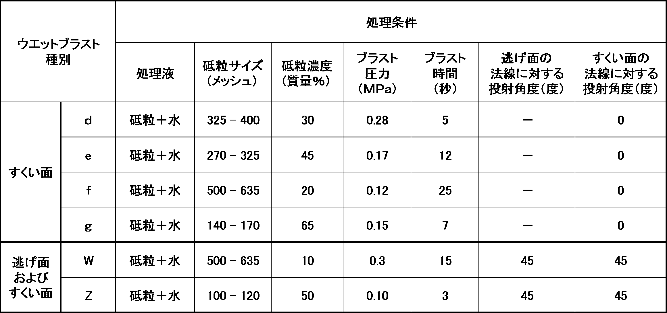
- Blast processing Speaking of more specific conditions for blasting, for example, Blasting solution: Abrasive grains + water, Abrasive: Al 2 O 3 powder, Abrasive grain size: 150-500 (mesh), Abrasive grain concentration: 15-60 mass%, Blasting pressure: 0.06-0.24MPa Projection time: 3-20 seconds, blasting is applied to the rake face and flank face. Especially, by adjusting the blast pressure and projection time, the surface roughness Ra of the rake face and flank face, and the lower part The residual stress of the TiCN layer of the layer and the Al 2 O 3 layer of the upper layer are adjusted.
- the blasting liquid may be projected onto both the rake face and the flank face by adjusting the projection angle.
- a mixed phase of TiN phase and Al 2 O 3 phase or a mixed phase of TiNO phase and Al 2 O 3 phase is present on the outermost surface of the Al 2 O 3 layer on the flank near the cutting edge ridge line. It is formed, and whether the corner is used or not is determined by the color tone. At the same time, the surface smoothness of the flank in the vicinity of the cutting edge ridge is increased, the surface smoothness of the work material is improved, and the residual stress of the TiCN layer and Al 2 O 3 layer in the flank near the cutting edge ridge is increased. By mitigating, it is possible to suppress the occurrence of abnormal wear due to improved chipping resistance and peel resistance on the flank side.
- the rake face is excellent in welding resistance and chipping resistance
- the flank face including the cutting edge ridge line is excellent in surface smoothness and corner identification of the work material and abnormal wear.
- the coated tool of the present invention will be specifically described with reference to examples.
- an example is shown in which a WC-based cemented carbide is used as the tool base, but the same applies when a TiCN-based cermet is used as the tool base.
- WC powder, TiC powder, TiN powder, TaC powder, NbC powder, Cr 3 C 2 powder and Co powder each having an average particle diameter of 1 to 3 ⁇ m were prepared. After blending to the composition shown, adding wax, ball mill mixing in acetone for 24 hours, drying under reduced pressure, press-molding into a green compact of a predetermined shape at a pressure of 98 MPa, this green compact in a vacuum of 5 Pa, Inserts specified in ISO / CNMG120408 by vacuum sintering at a predetermined temperature within the range of 1370 to 1470 ° C. for 1 hour, sintering, and then performing a honing process of R: 0.05 mm on the cutting edge. Tool bases A to C made of WC-base cemented carbide having a shape were manufactured.
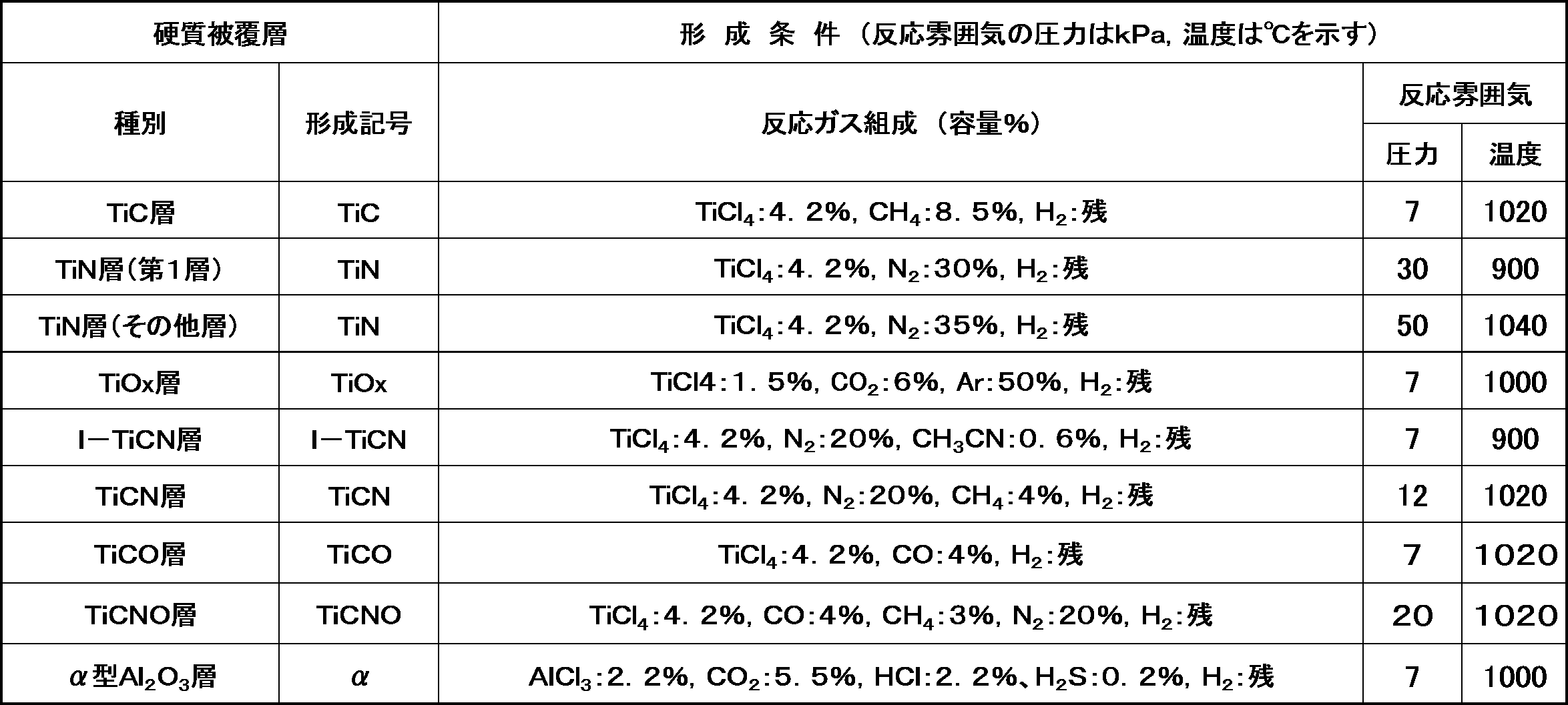
- Table 2 (l-TiCN in Table 2 indicates the conditions for forming a TiCN layer having a vertically grown crystal structure described in JP-A-6-8010, and other than that, a normal granular crystal structure is shown.
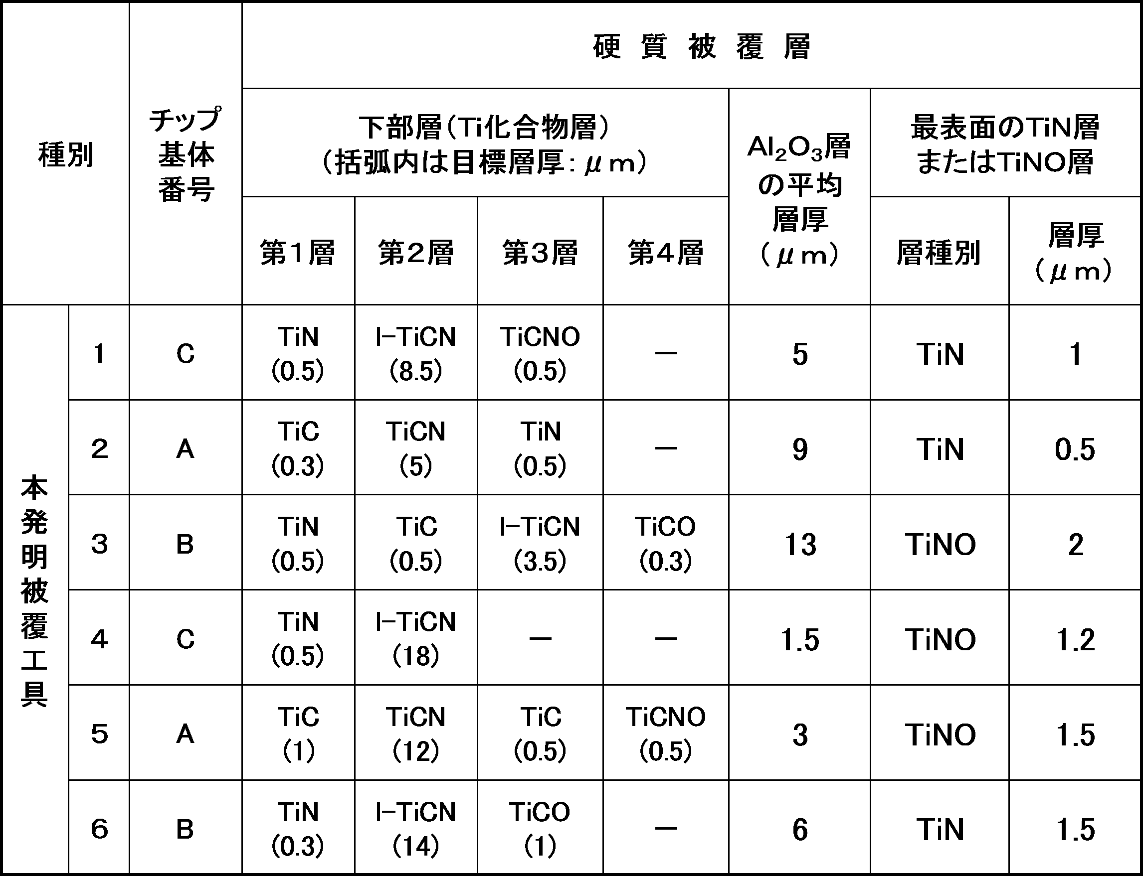
- the Ti compound layer having the target layer thickness shown in Table 3 was formed as a lower layer of the hard coating layer under the conditions shown in FIG.
- an Al 2 O 3 layer having a target layer thickness shown in Table 3 is formed by vapor deposition on the surface of the lower layer under the conditions shown in Table 2. Further, under the same conditions shown in Table 2, the Al 2 O 3 the TiN layer or TiNO layer of the target layer thicknesses shown in Table 3 was vapor deposited in three layers on.
- the area of the TiN phase or TiNO phase existing (residual) on the surface of the Al 2 O 3 layer of the rake face by performing EDS analysis on the outermost surface of the Al 2 O 3 layer of the coated tools 1 to 6 of the present invention. Further, the area ratio of the TiN phase or the TiNO phase constituting the mixed phase on the outermost surface of the Al 2 O 3 layer on the flank face was measured. Table 5 shows the measured area ratio of the TiN phase or the TiNO phase.
- the surface roughness Ra of the rake face and the flank face was measured for the inventive coated tools 1 to 6 produced as described above.
- the surface roughness Ra is measured in accordance with JIS B0601'01, with a cut-off value of 0.08 mm, a reference length of 0.8 mm, and a scanning speed of 0.1 mm / sec. It measured using the measuring device. Table 5 shows the results.
- the residual stress was measured for the Al 2 O 3 layer and the TiCN layer.
- the residual stress was measured using a sin 2 ⁇ method and an X-ray diffractometer using Cu ⁇ .
- ⁇ -Al 2 O 3 uses a diffraction peak of (13_10) plane
- Young's modulus is 384 GPa
- Poisson's ratio is 0.232
- TiCN uses a diffraction peak of (422) plane
- Young's modulus is 480 GPa.
- Table 5 shows the results.
- a Ti compound layer having the target layer thickness shown in Table 6 was applied to the hard coating layer under the conditions shown in Table 2 for the tool bases A to C made of the WC-base cemented carbide prepared above. After vapor-depositing as the lower layer, an Al 2 O 3 layer having the target layer thickness shown in Table 6 is vapor-deposited on the surface of the lower layer under the conditions shown in Table 2, and the conditions shown in Table 2 are also given. Then, a TiN layer or a TiNO layer having a target layer thickness shown in Table 6 was formed on the Al 2 O 3 layer by vapor deposition.
- the TiN phase or TiNO phase existing (residual) on the outermost surface of the rake face Al 2 O 3 layer was measured.
- Table 8 shows the measured area ratio of the TiN phase or TiNO phase.
- the surface roughness Ra of the rake face and the flank face was measured by the same method as the coated tools 1 to 6 of the present invention, and the Al 2 O 3 layer and The residual stress of the TiCN layer was measured. Table 8 shows the results.
- the following cutting conditions A and cutting are performed in a state where each of the tool steel cutting tools is screwed with a fixing jig.
- a cutting test was performed under Condition B.
- ⁇ Cutting condition A Work material: JIS / S45C round bar, Cutting speed: 250 m / min, Cutting depth: 1.5 mm, Feed: 0.2 mm / rev, Cutting time: Dry cutting test of carbon steel under the condition of 20 minutes.
- ⁇ Cutting condition B Work material: JIS / SCM440 round bar, Cutting speed: 350 m / min, Cutting depth: 1.5 mm, Feed: 0.5 mm / rev, Cutting time: Dry high-speed high-feed cutting test of alloy steel under conditions of 10 minutes.
- the flank maximum wear width of the cutting edge was measured, and at the same time, the presence or absence of welding, the presence or absence of chipping, and the presence or absence of defects were observed, and the quality of the used corners was further observed. Further, after cutting, the finished surface accuracy (arithmetic average height (Ra ⁇ m) according to JIS B0601-2001) of the work material was measured. Tables 9 and 10 show the cutting test results.
- the coated tool of the present invention can improve the surface smoothness of both the rake face and the flank face. As a result, the welding resistance and the surface smoothness of the work material can be improved. The improvement of the property is achieved.
- a mixed phase of TiN phase and Al 2 O 3 phase or a mixed phase of TiNO phase and Al 2 O 3 phase is formed on the flank outermost surface. It is easy to distinguish unused corners and has excellent corner identification. Further, in the high-feed cutting, the Al 2 O 3 layer on the rake face, TiCN layer and the Al 2 O 3 layer of flank and TiCN layer, since the relaxation of residual stresses is achieved by blasting, due to the occurrence of abnormal wear Damage can be suppressed.
- the comparative coated tool even if it has excellent welding resistance, chipping resistance and chipping resistance, it is inferior in corner identification, and if it has excellent corner identification, The surface smoothness and abnormal wear resistance of the cutting material are inferior, and none of the corner discrimination and cutting performance are compatible.
- the coated tool of the present invention has excellent cutting performance and corner identification, it is possible to reduce the cost and increase the work by improving the performance of the cutting device, saving the cutting work, and saving energy. It is possible to realize sex.
Landscapes
- Engineering & Computer Science (AREA)
- Mechanical Engineering (AREA)
- Cutting Tools, Boring Holders, And Turrets (AREA)
- Chemical Vapour Deposition (AREA)
Abstract
耐溶着性、耐チッピング性、耐欠損性にすぐれ、かつ、コーナー識別性を備える表面被覆切削工具を提供する。 工具基体の表面に、少なくとも下部層と上部層とを含む硬質被覆層が形成された表面被覆切削工具において、下部層はTi化合物層からなり、前記表面被覆切削工具のすくい面には、下部層と、該下部層の表面に設けられたAl2O3層からなる硬質被覆層が形成され、前記すくい面の表面粗さRaは0.25μm以下であり、前記表面被覆切削工具の逃げ面には、前記下部層と、該下部層の表面に設けられたAl2O3層からなる硬質被覆層が形成され、かつ、逃げ面においては、前記Al2O3層の最表面に、TiN相とAl2O3相との混合相あるいはTiNO相とAl2O3相との混合相が形成され、前記混合相に占めるTiN相あるいはTiNO相の面積割合は、20~80面積%であり、前記逃げ面の表面粗さRaは0.30μm以下である表面被覆切削工具。
Description
この発明は、炭素鋼や合金鋼等の切削加工において、耐溶着性、耐チッピング性にすぐれ、さらに、コーナー識別性をも備えた表面被覆切削工具(以下、単に「被覆工具」という)に関するものである。
従来、炭化タングステン(以下、WCで示す)基超硬合金または炭窒化チタン(以下、TiCNで示す)基サーメットで構成された基体(以下、工具基体という)の表面に、下部層として、Tiの炭化物(以下、TiCで示す)層、窒化物(以下、同じくTiNで示す)層、炭窒化物(以下、TiCNで示す)層、炭酸化物(以下、TiCOで示す)層および炭窒酸化物(以下、TiCNOで示す)層のうちの1層または2層以上からなるTi化合物層、また、上部層として、α型結晶構造を有するAl2O3層からなる硬質被覆層を設けた被覆工具が知られている。そして、前記硬質被覆層を形成した被覆工具の切削性能を高めるために、従来から種々の提案がなされている。
例えば、特許文献1では、Ti化合物層からなる下部層とAl2O3層からなる上部層が形成された被覆工具において、上部層の全面に、TiN層で構成された研磨材層を化学蒸着で形成した後、工具取り付け孔周辺部の前記研磨材層を残して、ウエットブラスト処理を施すことにより、上部層を構成するAl2O3層の表面を研磨して、前記Al2O3層の切刃稜線部を含むすくい面および逃げ面の表面粗さをRa:0.2μm以下とすることによって、高速切削加工における耐チッピング性を向上させることが提案されている。
なお、ウエットブラスト処理を施すことによって、被覆工具の硬質被覆層表面を平滑化することは、例えば、特許文献2、特許文献3に示されるように、既に知られている技術である。
なお、ウエットブラスト処理を施すことによって、被覆工具の硬質被覆層表面を平滑化することは、例えば、特許文献2、特許文献3に示されるように、既に知られている技術である。
また、被覆工具のコーナー識別性(被覆工具のコーナーの使用前後の識別,未使用・使用済の判別)を付与するために、硬質被覆層の最表面に黄金色の色調を有するTiN層を蒸着形成した被覆工具も提案されている。
すなわち、コーナー識別性(被覆工具の使用前後の識別)を備えた被覆工具によれば、使用済みコーナーは、黄金色(TiN層の色調)から、黒灰色あるいは黒色(Al2O3層の呈する色調)に変化するため、肉眼によって色調変化を知ることができ、これにより、使用済みコーナーであるか未使用コーナーであるかを容易に判別することができるからである。
すなわち、コーナー識別性(被覆工具の使用前後の識別)を備えた被覆工具によれば、使用済みコーナーは、黄金色(TiN層の色調)から、黒灰色あるいは黒色(Al2O3層の呈する色調)に変化するため、肉眼によって色調変化を知ることができ、これにより、使用済みコーナーであるか未使用コーナーであるかを容易に判別することができるからである。
コーナー識別性を備えた被覆工具として、例えば、特許文献4には、被覆工具の硬質被覆層を少なくとも2層で構成し、該2層は、最外層をMeCxNyOz層とし、その内側の層は微細粒組織のAl2O3層であり、該2層を形成した後、ブラッシング処理あるいはブラスト処理を施すことによって、最外層のMeCxNyOz層を少なくともエッジラインに沿って取り除き、一方、逃げ面上のMeCxNyOz層については、そのまま逃げ面上に残留させることにより、被覆工具にコーナー識別性を付与することが提案されている。
また、特許文献5には、工具基体の少なくともすくい面には基層(例えば、Al2O3層)を設け、工具の逃げ面には使用状態表示層(例えば、TiN層)を形成したコーナー識別性を有する被覆工具が提案されており、さらに、このような被覆工具を製造する方法の一つとして、工具基体の全表面に基層(例えば、Al2O3層)を形成し、該基層(例えば、Al2O3層)上に使用状態表示層(例えば、TiN層)をコーティングし、その後、ブラシ掛け、サンドブラスト加工等によって、すくい面の使用状態表示層(例えば、TiN層)を除去することが提案されている(段落0021)。
また、特許文献6には、工具基体の本体上に基層(例えば、Al2O3層)を設け、該基層上の部分には基層とは異なった色の使用状態表示層を設け、該使用状態表示層は、逃げ面上であって、刃先稜線に対して垂直方向に0.2mm以上3.0mmの距離をもって広がった領域(A1)を除く領域(A2)の全面または部分の基層上に形成すること、前記領域(A1)における基層は、絶対値で0.1GPa以上圧縮残留応力を有すること、前記領域(A1)の面粗度RaをAμm、前記領域(A2)の面粗度RaをBμmとした場合、1.0>A/Bとすることが提案されている。また、基層への圧縮残留応力は、例えば、ブラスト法によって付与すること、さらに、領域(A1)を除く領域(A2)に使用状態表示層を形成する手段として、ブラシ操作、ブラスト加工を採用することによって、刃先稜線の平滑化を図り得ることが提案されている。
また、特許文献7には、刃先近傍の最外層を研磨することで、鋭利なAl2O3層表面の凸状部分が平坦に研磨されて島状に分布させ、それらの間に研磨されていないTiNからなる最外層を存在させることが提案されている。
前記特許文献1に示される被覆工具においては、ウエットブラスト処理によって、切刃稜線部を含むすくい面および逃げ面の表面平滑性を高めることができるので、すぐれた耐溶着性、耐チッピング性を発揮するが、コーナー識別機能を備えていないため、使用済みコーナーと未使用コーナーを判別することが困難である。
一方、前記特許文献4に示される被覆工具においては、逃げ面上にMeCxNyOz層を残しており、また、前記特許文献5に示される被覆工具においては、逃げ面上に使用状態表示層(例えば、TiN層)を残しているため、コーナーの使用・不使用を識別することは可能であるが、逃げ面の表面平滑性に劣るとともに、Al2O3層の引張残留応力の低減も十分ではないため、耐溶着性、耐チッピング性が満足できるものではない。
前記特許文献6に示される被覆工具においては、刃先稜線に対して垂直方向に0.2mm以上3.0mmの距離をもって広がった領域(A1)は、領域(A1)の面粗度は領域(A2)の面粗度より小さいため、被削材の表面平滑性を害することはないものの、使用状態表示層をそのA2領域のみに精度良く形成することは困難である。
さらに、特許文献7に示される被覆工具においては、すくい面にTiNを残していることから耐チッピング性が満足できるものでなく、また、切屑の接触のみしか考慮していないために、摩耗量によっては被削材との接触部分は切刃近傍を超えて被削材表面に荒れが発生することになる。
そこで、被覆工具として、被削材の表面平滑性を害することがなく、耐溶着性、耐チッピング性、耐欠損性にすぐれた切削性能を有すると同時に、コーナーの使用・不使用を容易に識別可能とした被覆工具が求められている。
一方、前記特許文献4に示される被覆工具においては、逃げ面上にMeCxNyOz層を残しており、また、前記特許文献5に示される被覆工具においては、逃げ面上に使用状態表示層(例えば、TiN層)を残しているため、コーナーの使用・不使用を識別することは可能であるが、逃げ面の表面平滑性に劣るとともに、Al2O3層の引張残留応力の低減も十分ではないため、耐溶着性、耐チッピング性が満足できるものではない。
前記特許文献6に示される被覆工具においては、刃先稜線に対して垂直方向に0.2mm以上3.0mmの距離をもって広がった領域(A1)は、領域(A1)の面粗度は領域(A2)の面粗度より小さいため、被削材の表面平滑性を害することはないものの、使用状態表示層をそのA2領域のみに精度良く形成することは困難である。
さらに、特許文献7に示される被覆工具においては、すくい面にTiNを残していることから耐チッピング性が満足できるものでなく、また、切屑の接触のみしか考慮していないために、摩耗量によっては被削材との接触部分は切刃近傍を超えて被削材表面に荒れが発生することになる。
そこで、被覆工具として、被削材の表面平滑性を害することがなく、耐溶着性、耐チッピング性、耐欠損性にすぐれた切削性能を有すると同時に、コーナーの使用・不使用を容易に識別可能とした被覆工具が求められている。
本発明者等は、被削材の表面平滑性を害することがなく、耐溶着性、耐チッピング性、耐欠損性という切削性能を向上させるとともに、コーナーの使用・不使用を容易に識別することができる硬質被覆層の構造について鋭意研究を重ねた結果、次のような知見を得た。
即ち、工具基体表面に、硬質被覆層として少なくともAl2O3層を被覆形成した被覆工具において、すくい面の最表面の主体を前記Al2O3層で構成し、一方、逃げ面の最表面を、平滑な、TiN相とAl2O3相との混合相あるいはTiNO相とAl2O3相との混合相として形成した場合には、被削材の表面平滑性や、耐溶着性、耐チッピング性、耐欠損性を損なうことなく、しかも、コーナーの使用・不使用を容易に識別し得ることを見出したのである。
つまり、本発明の被覆工具によれば、逃げ面に形成された硬質被覆層の最表面は、平滑な、TiN相とAl2O3相との混合相あるいはTiNO相とAl2O3相との混合相として構成されているため、未使用のコーナー部は黄金色(TiN相の呈する色調)あるいはクリーム色(TiNO相の呈する色調)を呈しており、使用後は黒灰色あるいは黒色(Al2O3層の呈する色調)に変化するため、色調変化を知ることによって、使用済みコーナーであるか未使用コーナーであるかを容易にかつ確実に判別することができる。
なお、本発明においては、逃げ面の全ての最表面を前記混合相で構成することは必要とされず、コーナーの使用・不使用を識別するに足る箇所、即ち、一部の逃げ面の最表面が前記混合相で形成されていてもよい。
つまり、本発明の被覆工具によれば、逃げ面に形成された硬質被覆層の最表面は、平滑な、TiN相とAl2O3相との混合相あるいはTiNO相とAl2O3相との混合相として構成されているため、未使用のコーナー部は黄金色(TiN相の呈する色調)あるいはクリーム色(TiNO相の呈する色調)を呈しており、使用後は黒灰色あるいは黒色(Al2O3層の呈する色調)に変化するため、色調変化を知ることによって、使用済みコーナーであるか未使用コーナーであるかを容易にかつ確実に判別することができる。
なお、本発明においては、逃げ面の全ての最表面を前記混合相で構成することは必要とされず、コーナーの使用・不使用を識別するに足る箇所、即ち、一部の逃げ面の最表面が前記混合相で形成されていてもよい。
そして、前記TiN相とAl2O3相との混合相あるいはTiNO相とAl2O3相との混合相は、例えば、工具基体のすくい面及び逃げ面に少なくともAl2O3層を形成し、該Al2O3層表面に、TiN層あるいはTiNO層を形成し、次いで、すくい面からはTiN層あるいはTiNO層のほとんど全てを除去して、すくい面の最表面のTiN相あるいはTiNO相の残存率を5面積%以下とし、一方、逃げ面については、形成されたTiN層あるいはTiNO層の少なくとも一部を除去することによって、逃げ面の最表面にTiN相とAl2O3相との混合相あるいはTiNO相とAl2O3相との混合相を形成することができる。
前記すくい面におけるTiN層あるいはTiNO層のほとんど全てを除去する方法、また、逃げ面についてのTiN層あるいはTiNO層の一部を除去する方法については、例えば、特許文献3に示されるブラスト処理装置を使用して行うことができる。
すなわち、すくい面に対するブラスト条件と切れ刃稜線を含む逃げ面に対するブラスト条件を個別に調整することによって、すくい面の硬質被覆層における最表面はAl2O3層主体で構成(すくい面の硬質被覆層の最表面に残存するTiN相あるいはTiNO相の面積割合が5面積%以下であれば可)し、一方、逃げ面においては、TiN相とAl2O3相との混合相あるいはTiNO相とAl2O3相との混合相を硬質被覆層の最表面として構成することができる。
そして、逃げ面の最表面として、平滑な、TiN相とAl2O3相との混合相あるいはTiNO相とAl2O3相との混合相が形成されることによって、被削材の表面平滑性を向上させ、また、これらの混合相の色調変化から、使用済のコーナーであるか未使用のコーナーであるかを容易に判別することができる。
前記すくい面におけるTiN層あるいはTiNO層のほとんど全てを除去する方法、また、逃げ面についてのTiN層あるいはTiNO層の一部を除去する方法については、例えば、特許文献3に示されるブラスト処理装置を使用して行うことができる。
すなわち、すくい面に対するブラスト条件と切れ刃稜線を含む逃げ面に対するブラスト条件を個別に調整することによって、すくい面の硬質被覆層における最表面はAl2O3層主体で構成(すくい面の硬質被覆層の最表面に残存するTiN相あるいはTiNO相の面積割合が5面積%以下であれば可)し、一方、逃げ面においては、TiN相とAl2O3相との混合相あるいはTiNO相とAl2O3相との混合相を硬質被覆層の最表面として構成することができる。
そして、逃げ面の最表面として、平滑な、TiN相とAl2O3相との混合相あるいはTiNO相とAl2O3相との混合相が形成されることによって、被削材の表面平滑性を向上させ、また、これらの混合相の色調変化から、使用済のコーナーであるか未使用のコーナーであるかを容易に判別することができる。
また、すくい面については、TiN層あるいはTiNO層の除去ばかりでなく、ブラスト条件を調整することにより、Al2O3層の表面平滑性を高めることにより、耐溶着性を向上させることができ、さらに、残留応力の低減を図ることができるため、耐チッピング性と耐欠損性を向上させることができる。一方、逃げ面については、ブラスト処理によって形成されるTiN相とAl2O3相との混合相あるいはTiNO相とAl2O3相との混合相によって、コーナー識別性が高められることに加え、TiN層あるいはTiNO層が逃げ面にそのまま存在する場合に比して、ブラスト処理でTiN層あるいはTiNO層を除去することによって、逃げ面の表面平滑性を高めることができ、これによって被削材の表面平滑性を改善することができる。
したがって、本発明の被覆工具は、すくい面が、耐溶着性、耐チッピング性にすぐれ、また、逃げ面は、被削材の表面平滑性およびコーナー識別性にすぐれることから、長期の使用にわたって、すぐれた切削性能を発揮するとともに、インサートのコーナー切替えに際しても、コーナーの色調変化によって使用済コーナーと未使用コーナーを容易にかつ確実に判別することができるのである。
本発明は、上記の知見に基づいてなされたものであって、
「(1) WC基超硬合金またはTiCN基サーメットからなる工具基体の表面に、少なくとも下部層と上部層とを含む硬質被覆層が形成されている表面被覆切削工具において、
(a)前記硬質被覆層の下部層は、TiC層、TiN層、TiCN層、TiCO層およびTiCNO層のうちの1層または2層以上からなり、
(b)前記表面被覆切削工具のすくい面には、前記下部層と、該下部層の表面に設けられた上部層のAl2O3層からなる硬質被覆層が形成されており、前記すくい面の表面粗さRaは0.25μm以下であり、
(c)前記表面被覆切削工具の逃げ面には、前記下部層と、該下部層の表面に設けられた上部層のAl2O3層からなる硬質被覆層が形成されており、かつ、逃げ面においては、前記Al2O3層の最表面に、TiN相とAl2O3相との混合相あるいはTiNO相とAl2O3相との混合相が形成されており、前記逃げ面の表面粗さRaは0.30μm以下であることを特徴とする表面被覆切削工具。
(2) 前記(1)に記載の表面被覆切削工具において、前記混合相に占めるTiN相あるいはTiNO相の面積割合は、20~80面積%であることを特徴とする前記(1)に記載の表面被覆切削工具。
(3) 前記(1)または(2)に記載の表面被覆切削工具において、すくい面の上部層である前記Al2O3層の最表面には、5面積%以下のTiN相あるいはTiNO相が存在することを特徴とする前記(1)または(2)に記載の表面被覆切削工具。
(4) 前記(1)乃至(3)のいずれかに記載の表面被覆切削工具において、前記下部層として少なくとも1層のTiCN層が形成されており、すくい面のTiCN層は50~350MPaの引張残留応力を有し、逃げ面のTiCN層は400~600MPaの引張残留応力を有し、また、すくい面の前記Al2O3層は10~300MPaの引張残留応力を有し、逃げ面の前記Al2O3層は350~600MPaの引張残留応力を有することを特徴とする前記(1)乃至(3)のいずれかに記載の表面被覆切削工具。」
に特徴を有するものである。
「(1) WC基超硬合金またはTiCN基サーメットからなる工具基体の表面に、少なくとも下部層と上部層とを含む硬質被覆層が形成されている表面被覆切削工具において、
(a)前記硬質被覆層の下部層は、TiC層、TiN層、TiCN層、TiCO層およびTiCNO層のうちの1層または2層以上からなり、
(b)前記表面被覆切削工具のすくい面には、前記下部層と、該下部層の表面に設けられた上部層のAl2O3層からなる硬質被覆層が形成されており、前記すくい面の表面粗さRaは0.25μm以下であり、
(c)前記表面被覆切削工具の逃げ面には、前記下部層と、該下部層の表面に設けられた上部層のAl2O3層からなる硬質被覆層が形成されており、かつ、逃げ面においては、前記Al2O3層の最表面に、TiN相とAl2O3相との混合相あるいはTiNO相とAl2O3相との混合相が形成されており、前記逃げ面の表面粗さRaは0.30μm以下であることを特徴とする表面被覆切削工具。
(2) 前記(1)に記載の表面被覆切削工具において、前記混合相に占めるTiN相あるいはTiNO相の面積割合は、20~80面積%であることを特徴とする前記(1)に記載の表面被覆切削工具。
(3) 前記(1)または(2)に記載の表面被覆切削工具において、すくい面の上部層である前記Al2O3層の最表面には、5面積%以下のTiN相あるいはTiNO相が存在することを特徴とする前記(1)または(2)に記載の表面被覆切削工具。
(4) 前記(1)乃至(3)のいずれかに記載の表面被覆切削工具において、前記下部層として少なくとも1層のTiCN層が形成されており、すくい面のTiCN層は50~350MPaの引張残留応力を有し、逃げ面のTiCN層は400~600MPaの引張残留応力を有し、また、すくい面の前記Al2O3層は10~300MPaの引張残留応力を有し、逃げ面の前記Al2O3層は350~600MPaの引張残留応力を有することを特徴とする前記(1)乃至(3)のいずれかに記載の表面被覆切削工具。」
に特徴を有するものである。
以下に、この発明の被覆工具について、詳細に説明する。
下部層:
Ti化合物層からなる下部層は、基本的には、Al2O3層からなる上部層の下部に設けられ、工具基体と上部層のいずれにも強固に密着し、硬質被覆層の工具基体に対する密着性向上に寄与する作用を有するが、下部層自身の特性である高い硬度によって硬質被覆層に高い耐摩耗性、特に優れた耐逃げ面摩耗性を具備する。
このような下部層に好適な膜種としては、TiC層、TiN層、TiCN層、TiCO層およびTiCNO層のうちの1層または2層以上のTi化合物層を挙げることができ、これらの層のうちの1層または2層以上により下部層を構成する。
また、下部層の平均層厚については特に限定するものではないが、その平均層厚が3μm未満では、前記作用を十分に発揮させることができず、一方、その平均層厚が20μmを越えると、耐欠損性に悪影響を及ぼすことから、下部層の平均層厚は3~20μmとすることが望ましい。
Ti化合物層からなる下部層は、基本的には、Al2O3層からなる上部層の下部に設けられ、工具基体と上部層のいずれにも強固に密着し、硬質被覆層の工具基体に対する密着性向上に寄与する作用を有するが、下部層自身の特性である高い硬度によって硬質被覆層に高い耐摩耗性、特に優れた耐逃げ面摩耗性を具備する。
このような下部層に好適な膜種としては、TiC層、TiN層、TiCN層、TiCO層およびTiCNO層のうちの1層または2層以上のTi化合物層を挙げることができ、これらの層のうちの1層または2層以上により下部層を構成する。
また、下部層の平均層厚については特に限定するものではないが、その平均層厚が3μm未満では、前記作用を十分に発揮させることができず、一方、その平均層厚が20μmを越えると、耐欠損性に悪影響を及ぼすことから、下部層の平均層厚は3~20μmとすることが望ましい。
上部層:
Al2O3層からなる上部層は、その硬さ、耐熱性、耐酸化性によって、被覆工具の耐摩耗性を向上させる。本発明では、上部層の層厚を特に制限するものではないが、Al2O3層の平均層厚が1μm未満では長期の使用にわたってすぐれた耐摩耗性発揮することができず、一方、その平均層厚が15μmを超えると、チッピング、欠損、剥離等の異常損傷を発生しやすくなる。したがって、Al2O3層からなる上部層の平均層厚は1~15μmとすることが望ましい。
Al2O3層からなる上部層は、その硬さ、耐熱性、耐酸化性によって、被覆工具の耐摩耗性を向上させる。本発明では、上部層の層厚を特に制限するものではないが、Al2O3層の平均層厚が1μm未満では長期の使用にわたってすぐれた耐摩耗性発揮することができず、一方、その平均層厚が15μmを超えると、チッピング、欠損、剥離等の異常損傷を発生しやすくなる。したがって、Al2O3層からなる上部層の平均層厚は1~15μmとすることが望ましい。
すくい面の硬質被覆層:
本発明被覆工具の硬質被覆層は、すくい面と逃げ面とでその構造が異なる。
まず、すくい面の硬質被覆層について説明する。
すくい面に形成される硬質被覆層は、Ti化合物層からなる下部層と、Al2O3層からなる上部層とで構成されるが、Al2O3層の最表面に、5面積%以下のTiN相あるいはTiNO相が存在することが許容される。
すなわち、後記する本発明被覆工具の製造法の一例によれば、まず、工具基体のすくい面および逃げ面に下部層としてのTi化合物層を形成し、ついで、下部層表面に上部層としてのAl2O3層を形成し、ついで、上部層の表面にさらにTiN層あるいはTiNO層を形成し、その後、すくい面については、すくい面のAl2O3層の表面平滑性を高め、同時に、残留応力の低減を図るためのブラスト処理を行い、Al2O3層上のTiN層あるいはTiNO層を完全に除去する。
なお、完全に除去しない場合であっても、すくい面のAl2O3層の最表面に残存するTiN相あるいはTiNO相の残存面積割合が5面積%以下となるようにTiN層あるいはTiNO層を除去する。
すくい面のAl2O3層の最表面におけるTiN相あるいはTiNO相の残存量が、面積割合で5面積%以下であれば、すくい面の上部層としてのAl2O3層の硬さ、耐熱性、耐酸化性には大きな影響を及ぼすことはなく、また、表面平滑性と残留応力についても悪影響を及ぼすことはないので、TiN相あるいはTiNO相がAl2O3層の最表面に5面積%以下残存することは許容される。
本発明被覆工具の硬質被覆層は、すくい面と逃げ面とでその構造が異なる。
まず、すくい面の硬質被覆層について説明する。
すくい面に形成される硬質被覆層は、Ti化合物層からなる下部層と、Al2O3層からなる上部層とで構成されるが、Al2O3層の最表面に、5面積%以下のTiN相あるいはTiNO相が存在することが許容される。
すなわち、後記する本発明被覆工具の製造法の一例によれば、まず、工具基体のすくい面および逃げ面に下部層としてのTi化合物層を形成し、ついで、下部層表面に上部層としてのAl2O3層を形成し、ついで、上部層の表面にさらにTiN層あるいはTiNO層を形成し、その後、すくい面については、すくい面のAl2O3層の表面平滑性を高め、同時に、残留応力の低減を図るためのブラスト処理を行い、Al2O3層上のTiN層あるいはTiNO層を完全に除去する。
なお、完全に除去しない場合であっても、すくい面のAl2O3層の最表面に残存するTiN相あるいはTiNO相の残存面積割合が5面積%以下となるようにTiN層あるいはTiNO層を除去する。
すくい面のAl2O3層の最表面におけるTiN相あるいはTiNO相の残存量が、面積割合で5面積%以下であれば、すくい面の上部層としてのAl2O3層の硬さ、耐熱性、耐酸化性には大きな影響を及ぼすことはなく、また、表面平滑性と残留応力についても悪影響を及ぼすことはないので、TiN相あるいはTiNO相がAl2O3層の最表面に5面積%以下残存することは許容される。
すくい面のAl2O3層の最表面のTiN層、TiNO層を適切な条件のブラスト処理によって除去する(TiN相あるいはTiNO相の残存面積割合が5面積%以下とする除去も含む)と、Al2O3層の表面は平滑化され、同時に、Al2O3層内の残留応力が緩和され、また、下部層を構成するTi化合物層であるTiCN層内の残留応力も緩和される。
ただ、ブラスト処理後のすくい面の表面粗さRaが0.25μmを超えるような場合には、切削加工時の耐溶着性が十分ではないため、溶着に起因する異常損傷の発生の抑制効果が小さい。したがって、すくい面の表面粗さRaは0.25μm以下とする。
また、ブラスト処理によってAl2O3層内の残留応力を緩和し、引張残留応力の値を10~300MPaにし、さらに、下部層の構成層であるTiCN層内の引張残留応力を50~350MPaにすると、硬質被覆層全体としての耐チッピング性、耐欠損性、耐剥離性が向上する。
つまり、すくい面のAl2O3層の最表面のTiN層、TiNO層をブラスト処理によって除去し(TiN相あるいはTiNO相の残存面積割合が5面積%以下とする除去も含む)、すくい面を所定の表面粗さ、残留応力とすること、さらに、ブラスト処理によって下部層の構成層であるTiCN層内の残留応力を緩和することによって、切削加工時における耐溶着性、耐チッピング性、耐欠損性、耐剥離性が向上する。
ただ、ブラスト処理後のすくい面の表面粗さRaが0.25μmを超えるような場合には、切削加工時の耐溶着性が十分ではないため、溶着に起因する異常損傷の発生の抑制効果が小さい。したがって、すくい面の表面粗さRaは0.25μm以下とする。
また、ブラスト処理によってAl2O3層内の残留応力を緩和し、引張残留応力の値を10~300MPaにし、さらに、下部層の構成層であるTiCN層内の引張残留応力を50~350MPaにすると、硬質被覆層全体としての耐チッピング性、耐欠損性、耐剥離性が向上する。
つまり、すくい面のAl2O3層の最表面のTiN層、TiNO層をブラスト処理によって除去し(TiN相あるいはTiNO相の残存面積割合が5面積%以下とする除去も含む)、すくい面を所定の表面粗さ、残留応力とすること、さらに、ブラスト処理によって下部層の構成層であるTiCN層内の残留応力を緩和することによって、切削加工時における耐溶着性、耐チッピング性、耐欠損性、耐剥離性が向上する。
逃げ面の硬質被覆層:
逃げ面に形成される硬質被覆層は、Ti化合物層からなる下部層と、Al2O3層からなる上部層と、Al2O3層の最表面に形成されるTiN相とAl2O3相との混合相あるいはTiNO相とAl2O3相との混合相からなる。
逃げ面に形成される硬質被覆層は、Ti化合物層からなる下部層と、Al2O3層からなる上部層と、Al2O3層の最表面に形成されるTiN相とAl2O3相との混合相あるいはTiNO相とAl2O3相との混合相からなり、該逃げ面の表面粗さRaは0.30μm以下である。
逃げ面に形成される硬質被覆層は、Ti化合物層からなる下部層と、Al2O3層からなる上部層と、Al2O3層の最表面に形成されるTiN相とAl2O3相との混合相あるいはTiNO相とAl2O3相との混合相からなる。
逃げ面に形成される硬質被覆層は、Ti化合物層からなる下部層と、Al2O3層からなる上部層と、Al2O3層の最表面に形成されるTiN相とAl2O3相との混合相あるいはTiNO相とAl2O3相との混合相からなり、該逃げ面の表面粗さRaは0.30μm以下である。
逃げ面に前記混合相を形成するため、また、逃げ面の表面粗さを所定範囲にするためには、後記するようにブラスト条件を調整する必要があるが、前記混合相に占めるTiN相あるいはTiNO相の面積割合が20面積%未満の場合には、使用済コーナーと未使用コーナーとの色調変化が少ないため、色調の区別が困難であって、コーナー識別性に劣る。
一方、TiN相あるいはTiNO相の面積割合が80面積%を超えると、逃げ面の表面粗さRaが0.30μmを超え、逃げ面の表面平滑性が低下する結果、異常摩耗が発生しやすくなる。
したがって、表面平滑化を図ると同時に、ブラスト処理による残留応力緩和効果を得るためには、逃げ面における前記逃げ面の表面粗さRaは0.3μm以下と定め、また、Al2O3層の最表面に形成されるTiN相とAl2O3相との混合相あるいはTiNO相とAl2O3相との混合相に占めるTiN相あるいはTiNO相の面積割合は、20~80面積%とすることが望ましい。
さらに、ブラスト処理により、逃げ面に形成される前記Al2O3層の引張残留応力を350~600MPaに低減し、また、下部層の構成層であるTiCN層内の引張残留応力を400~600MPaに低減することによって、チッピング、剥離等による異常摩耗を抑制することができる。
一方、TiN相あるいはTiNO相の面積割合が80面積%を超えると、逃げ面の表面粗さRaが0.30μmを超え、逃げ面の表面平滑性が低下する結果、異常摩耗が発生しやすくなる。
したがって、表面平滑化を図ると同時に、ブラスト処理による残留応力緩和効果を得るためには、逃げ面における前記逃げ面の表面粗さRaは0.3μm以下と定め、また、Al2O3層の最表面に形成されるTiN相とAl2O3相との混合相あるいはTiNO相とAl2O3相との混合相に占めるTiN相あるいはTiNO相の面積割合は、20~80面積%とすることが望ましい。
さらに、ブラスト処理により、逃げ面に形成される前記Al2O3層の引張残留応力を350~600MPaに低減し、また、下部層の構成層であるTiCN層内の引張残留応力を400~600MPaに低減することによって、チッピング、剥離等による異常摩耗を抑制することができる。
なお、すくい面のAl2O3層の最表面におけるTiN相あるいはTiNO相の面積割合、また、逃げ面のAl2O3層の最表面に形成されるTiN相とAl2O3相との混合相あるいはTiNO相とAl2O3相との混合相の面積割合は、すくい面および逃げ面のそれぞれについてのEDS分析を行うことによって測定したそれぞれの面積率をいう。
また、表面粗さRaは、例えば、JIS B0601’01に準拠して触針式表面粗さ測定器を用いて測定することができ、この場合、カットオフ値:0.08mm、基準長さ:0.8mm、走査速度:0.1mm/秒にて測定する値とする。
また、上部層でAl2O3層の残留応力、下部層の構成層であるTiCN層の残留応力は、例えば、sin2Ψ法を用い、Cuκαを用いたX線回折装置を用いて測定する。測定にはα-Al2O3については(13_10)面の回折ピークを用い、ヤング率として384GPa、ポアソン比として0.232、TiCNについては(422)面の回折ピークを用い、ヤング率として480GPa、ポアソン比として0.2を使用して計算を実施する。
また、表面粗さRaは、例えば、JIS B0601’01に準拠して触針式表面粗さ測定器を用いて測定することができ、この場合、カットオフ値:0.08mm、基準長さ:0.8mm、走査速度:0.1mm/秒にて測定する値とする。
また、上部層でAl2O3層の残留応力、下部層の構成層であるTiCN層の残留応力は、例えば、sin2Ψ法を用い、Cuκαを用いたX線回折装置を用いて測定する。測定にはα-Al2O3については(13_10)面の回折ピークを用い、ヤング率として384GPa、ポアソン比として0.232、TiCNについては(422)面の回折ピークを用い、ヤング率として480GPa、ポアソン比として0.2を使用して計算を実施する。
硬質被覆層の作製法:
本発明の硬質被覆層は、例えば、以下の方法によって作製することができる。
まず、工具基体表面に、通常の化学蒸着法によって、下部層としてのTi化合物層および上部層としてのAl2O3層を所定の平均層厚で形成し、
次いで、上部層のAl2O3層の表面に、通常の化学蒸着法によって、コーナー識別機能を有する色調のTiN層あるいはTiNO層を平均層厚は0.1~1μm程度の層厚になるように形成する。
なお、TiNO層は、まず、TiOx層を形成し、次いで、前記TiOx層の上に通常の条件でTiN層を蒸着形成することで、前記TiOx層から前記TiN層への酸素の拡散反応によって形成する。
次いで、実質的にすくい面のみにウエットブラスト処理を施し、すくい面に形成されたTiN層あるいはTiNO層を完全に除去し、あるいは、Al2O3層の最表面におけるTiN相あるいはTiNO相の残存量が、面積割合で5面積%以下になるように除去し、
次いで、実質的に逃げ面のみにウエットブラスト処理を施し、逃げ面のAl2O3層の最表面に形成されるTiN相とAl2O3相との混合相あるいはTiNO相とAl2O3相との混合相が、面積割合で20~80面積%となるように処理することにより、作製することができる。
本発明の硬質被覆層は、例えば、以下の方法によって作製することができる。
まず、工具基体表面に、通常の化学蒸着法によって、下部層としてのTi化合物層および上部層としてのAl2O3層を所定の平均層厚で形成し、
次いで、上部層のAl2O3層の表面に、通常の化学蒸着法によって、コーナー識別機能を有する色調のTiN層あるいはTiNO層を平均層厚は0.1~1μm程度の層厚になるように形成する。
なお、TiNO層は、まず、TiOx層を形成し、次いで、前記TiOx層の上に通常の条件でTiN層を蒸着形成することで、前記TiOx層から前記TiN層への酸素の拡散反応によって形成する。
次いで、実質的にすくい面のみにウエットブラスト処理を施し、すくい面に形成されたTiN層あるいはTiNO層を完全に除去し、あるいは、Al2O3層の最表面におけるTiN相あるいはTiNO相の残存量が、面積割合で5面積%以下になるように除去し、
次いで、実質的に逃げ面のみにウエットブラスト処理を施し、逃げ面のAl2O3層の最表面に形成されるTiN相とAl2O3相との混合相あるいはTiNO相とAl2O3相との混合相が、面積割合で20~80面積%となるように処理することにより、作製することができる。
ブラスト処理:
ブラスト処理のより具体的な条件をいえば、例えば、
ブラスト処理液:砥粒+水、
砥粒:Al2O3粉粒、
砥粒サイズ:150-500(メッシュ)、
砥粒濃度:15-60質量%、
ブラスト圧力:0.06-0.24MPa
投射時間:3-20秒
という条件で、すくい面および逃げ面にそれぞれブラスト処理を施し、特に、ブラスト圧力、投射時間を調整することで、すくい面および逃げ面の表面粗さRa、および、下部層のTiCN層および上部層のAl2O3層の残留応力を調整する。
なお、投射角度を調整して、ブラスト処理液をすくい面および逃げ面の両方に投射しても構わない。
ブラスト処理のより具体的な条件をいえば、例えば、
ブラスト処理液:砥粒+水、
砥粒:Al2O3粉粒、
砥粒サイズ:150-500(メッシュ)、
砥粒濃度:15-60質量%、
ブラスト圧力:0.06-0.24MPa
投射時間:3-20秒
という条件で、すくい面および逃げ面にそれぞれブラスト処理を施し、特に、ブラスト圧力、投射時間を調整することで、すくい面および逃げ面の表面粗さRa、および、下部層のTiCN層および上部層のAl2O3層の残留応力を調整する。
なお、投射角度を調整して、ブラスト処理液をすくい面および逃げ面の両方に投射しても構わない。
そして、これによって、切れ刃稜線近傍の逃げ面には、Al2O3層の最表面にTiN相とAl2O3相との混合相あるいはTiNO相とAl2O3相との混合相が形成され、コーナー使用・未使用がその色調によって判別される。
また、同時に、切れ刃稜線近傍の逃げ面の表面平滑性が高まり、被削材の表面平滑性が向上するとともに、切れ刃稜線近傍の逃げ面のTiCN層、Al2O3層の残留応力が緩和されることによって、逃げ面側の耐チッピング性、耐剥離性の向上による異常摩耗の発生を抑制することができる。
また、同時に、切れ刃稜線近傍の逃げ面の表面平滑性が高まり、被削材の表面平滑性が向上するとともに、切れ刃稜線近傍の逃げ面のTiCN層、Al2O3層の残留応力が緩和されることによって、逃げ面側の耐チッピング性、耐剥離性の向上による異常摩耗の発生を抑制することができる。
本発明の被覆工具は、すくい面が、耐溶着性、耐チッピング性にすぐれ、また、切れ刃稜線を含む逃げ面は、被削材の表面平滑性やコーナー識別性にすぐれるとともに、異常摩耗の発生も抑制することから、長期の使用にわたって、すぐれた切削性能を発揮するとともに、インサートのコーナー切替えに際しても、コーナーの色調変化によって使用済コーナーと未使用コーナーを容易にかつ確実に判別することができる。
つぎに、この発明の被覆工具を実施例により具体的に説明する。
なお、ここでは、工具基体として、WC基超硬合金を使用した例を示すが、工具基体として、TiCN基サーメットを使用した場合も同様である。
なお、ここでは、工具基体として、WC基超硬合金を使用した例を示すが、工具基体として、TiCN基サーメットを使用した場合も同様である。
原料粉末として、いずれも1~3μmの平均粒径を有するWC粉末、TiC粉末、TiN粉末、TaC粉末、NbC粉末、Cr3C2粉末およびCo粉末を用意し、これら原料粉末を、表1に示す配合組成に配合し、ワックスを加えてアセトン中で24時間ボールミル混合し、減圧乾燥した後、98MPaの圧力で所定形状の圧粉体にプレス成形し、この圧粉体を5Paの真空中、1370~1470℃の範囲内の所定の温度に1時間保持の条件で真空焼結し、焼結後、切刃部にR:0.05mmのホーニング加工を施すことによりISO・CNMG120408に規定するインサート形状のWC基超硬合金製の工具基体A~Cを製造した。
ついで、この工具基体を、通常の化学蒸着装置に装入し、
まず、表2(表2中のl-TiCNは特開平6-8010号公報に記載される縦長成長結晶組織をもつTiCN層の形成条件を示すものであり、これ以外は通常の粒状結晶組織の形成条件を示すものである)に示される条件にて、表3に示される目標層厚のTi化合物層を硬質被覆層の下部層として蒸着形成した。
まず、表2(表2中のl-TiCNは特開平6-8010号公報に記載される縦長成長結晶組織をもつTiCN層の形成条件を示すものであり、これ以外は通常の粒状結晶組織の形成条件を示すものである)に示される条件にて、表3に示される目標層厚のTi化合物層を硬質被覆層の下部層として蒸着形成した。
ついで、前記下部層の表面に、表2に示される条件で表3に示される目標層厚のAl2O3層を蒸着形成し、さらに、同じく表2に示される条件で、該Al2O3層上に表3に示される目標層厚のTiN層あるいはTiNO層を蒸着形成した。
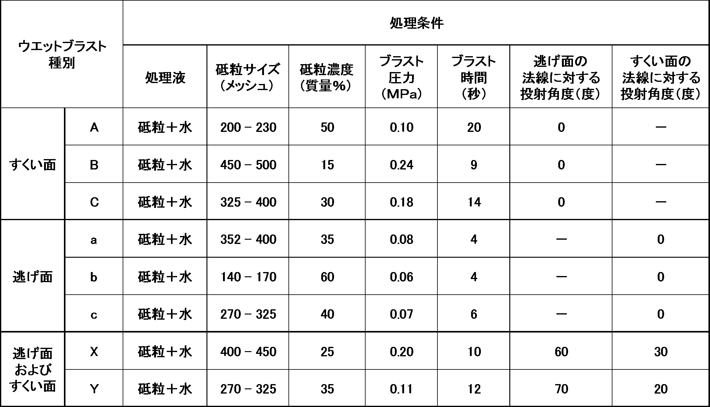
ついで、表4に示す条件で、すくい面および切れ刃稜線を含む少なくとも一部の逃げ面に対してウエットブラスト処理を施して、表5に示されるすくい面のAl2O3層および同じく表5に示される切れ刃稜線を含む少なくとも一部の逃げ面のAl2O3層を有する本発明被覆工具1~6を作製した。
上記本発明被覆工具1~6の下部層、上部層の厚さを、走査型電子顕微鏡を用いて測定(縦断面測定)したところ、いずれも目標層厚と実質的に同じ平均層厚(5点測定の平均値)を示した。
また、上記本発明被覆工具1~6のAl2O3層の最表面について、EDS分析することにより、すくい面のAl2O3層の表面に存在(残留)するTiN相あるいはTiNO相の面積率を測定し、また、逃げ面のAl2O3層の最表面において混合相を構成するTiN相あるいはTiNO相の面積率を測定した。
表5に、測定したTiN相あるいはTiNO相の面積率を示す。
表5に、測定したTiN相あるいはTiNO相の面積率を示す。
また、上記で作製した本発明被覆工具1~6について、すくい面および逃げ面の表面粗さRaを測定した。
なお、表面粗さRaの測定は、JIS B0601’01に準拠し、カットオフ値:0.08mm、基準長さ:0.8mm、走査速度:0.1mm/秒にて触針式表面粗さ測定器を用いて測定した。
表5に、その結果を示す。
なお、表面粗さRaの測定は、JIS B0601’01に準拠し、カットオフ値:0.08mm、基準長さ:0.8mm、走査速度:0.1mm/秒にて触針式表面粗さ測定器を用いて測定した。
表5に、その結果を示す。
さらに、上記で作製した本発明被覆工具1~6について、Al2O3層およびTiCN層について、残留応力を測定した。
残留応力はsin2Ψ法を用い、Cuκαを用いたX線回折装置を用いて測定した。測定にはα-Al2O3については(13_10)面の回折ピークを用い、ヤング率として384GPa、ポアソン比として0.232、TiCNについては(422)面の回折ピークを用い、ヤング率として480GPa、ポアソン比として0.2を使用して計算を実施した。表5に、その結果を示す。
残留応力はsin2Ψ法を用い、Cuκαを用いたX線回折装置を用いて測定した。測定にはα-Al2O3については(13_10)面の回折ピークを用い、ヤング率として384GPa、ポアソン比として0.232、TiCNについては(422)面の回折ピークを用い、ヤング率として480GPa、ポアソン比として0.2を使用して計算を実施した。表5に、その結果を示す。


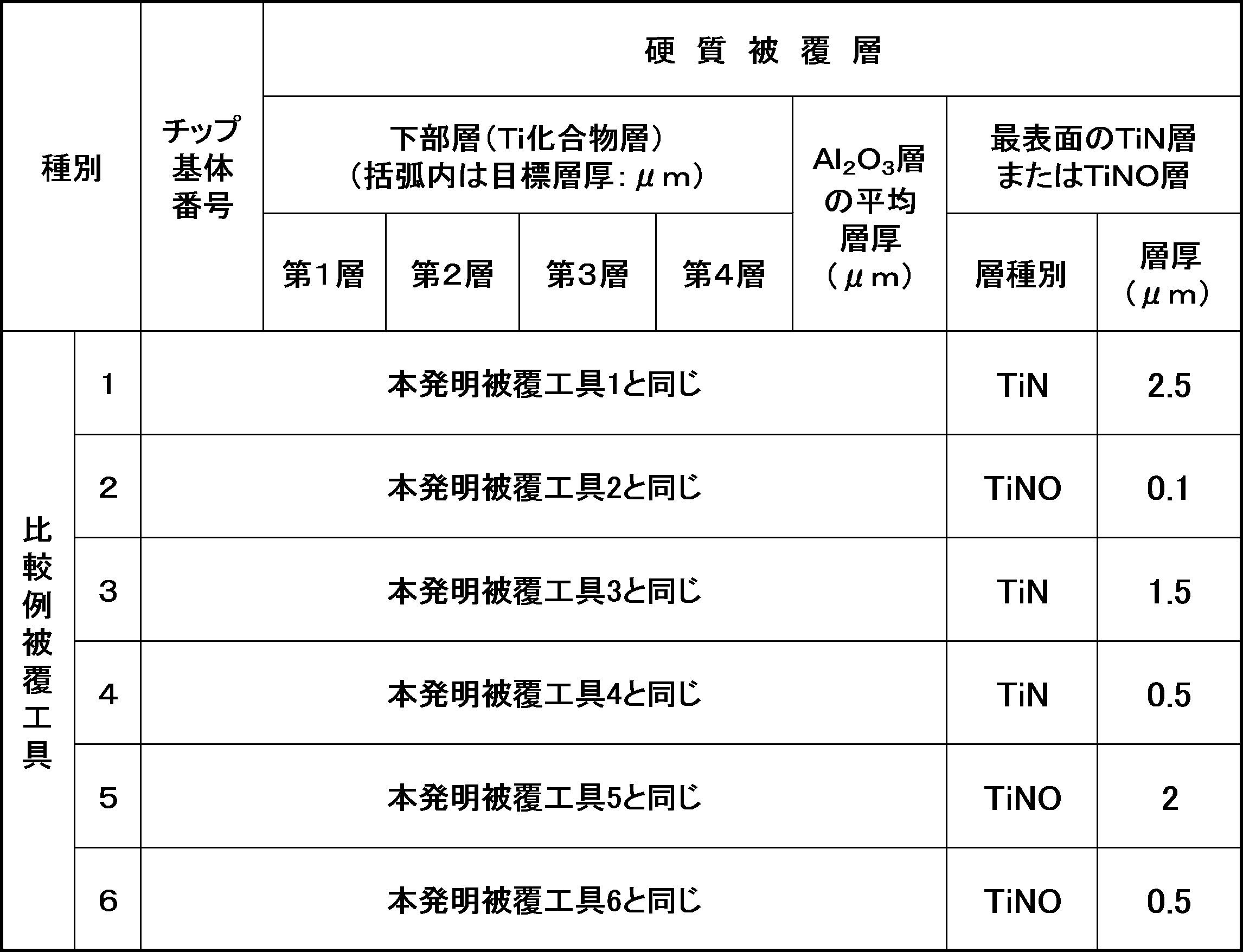
比較の目的で、前記で作製したWC基超硬合金製の工具基体A~Cに対して、表2に示される条件で、表6に示される目標層厚のTi化合物層を硬質被覆層の下部層として蒸着形成した後、該下部層の表面に、表2に示す条件で、表6に示される目標層厚のAl2O3層を蒸着形成し、さらに、同じく表2に示される条件で、該Al2O3層上に表6に示される目標層厚のTiN層あるいはTiNO層を蒸着形成した。
ついで、表7に示す条件で、すくい面および逃げ面に対してウエットブラスト処理を施して、表8に示されるすくい面のAl2O3層および同じく表8に示される逃げ面のAl2O3層を有する比較例被覆工具1~6を作製した。
上記比較例被覆工具1~6の下部層、上部層の厚さを、走査型電子顕微鏡を用いて測定(縦断面測定)したところ、いずれも目標層厚と実質的に同じ平均層厚(5点測定の平均値)を示した。
また、上記比較例被覆工具1~6のAl2O3層の最表面について、EDS分析することにより、すくい面のAl2O3層の最表面に存在(残留)するTiN相あるいはTiNO相の面積率、あるいは、逃げ面のAl2O3層の最表面において混合相を構成するTiN相あるいはTiNO相の面積率を測定した。
表8に、測定したTiN相あるいはTiNO相の面積率を示す。
表8に、測定したTiN相あるいはTiNO相の面積率を示す。
また、上記で作製した比較例被覆工具1~6について、本発明被覆工具1~6と同様な方法により、すくい面および逃げ面の表面粗さRaを測定し、さらに、Al2O3層およびTiCN層の残留応力を測定した。
表8に、その結果を示す。
表8に、その結果を示す。

つぎに、上記の本発明被覆工具1~6および比較例被覆工具1~6について、いずれも工具鋼製バイトの先端部に固定治具にてネジ止めした状態で、以下の切削条件Aおよび切削条件Bで切削試験を実施した。
≪切削条件A≫
被削材:JIS・S45Cの丸棒、
切削速度: 250 m/min、
切込み: 1.5 mm、
送り: 0.2 mm/rev、
切削時間: 20 分
の条件での炭素鋼の乾式切削試験。
≪切削条件B≫
被削材:JIS・SCM440の丸棒、
切削速度: 350 m/min、
切込み: 1.5 mm、
送り: 0.5 mm/rev、
切削時間: 10 分
の条件での合金鋼の乾式高速高送り切削試験。
上記切削試験において、切れ刃の逃げ面最大摩耗幅を測定すると同時に、溶着発生の有無、チッピング発生の有無、欠損発生の有無を観察し、さらに、使用コーナーの識別性の良否を観察した。また、切削後、被削材の仕上げ面精度(JIS B0601-2001による算術平均高さ(Raμm))を測定した。
表9および表10に切削試験結果を示す。
≪切削条件A≫
被削材:JIS・S45Cの丸棒、
切削速度: 250 m/min、
切込み: 1.5 mm、
送り: 0.2 mm/rev、
切削時間: 20 分
の条件での炭素鋼の乾式切削試験。
≪切削条件B≫
被削材:JIS・SCM440の丸棒、
切削速度: 350 m/min、
切込み: 1.5 mm、
送り: 0.5 mm/rev、
切削時間: 10 分
の条件での合金鋼の乾式高速高送り切削試験。
上記切削試験において、切れ刃の逃げ面最大摩耗幅を測定すると同時に、溶着発生の有無、チッピング発生の有無、欠損発生の有無を観察し、さらに、使用コーナーの識別性の良否を観察した。また、切削後、被削材の仕上げ面精度(JIS B0601-2001による算術平均高さ(Raμm))を測定した。
表9および表10に切削試験結果を示す。
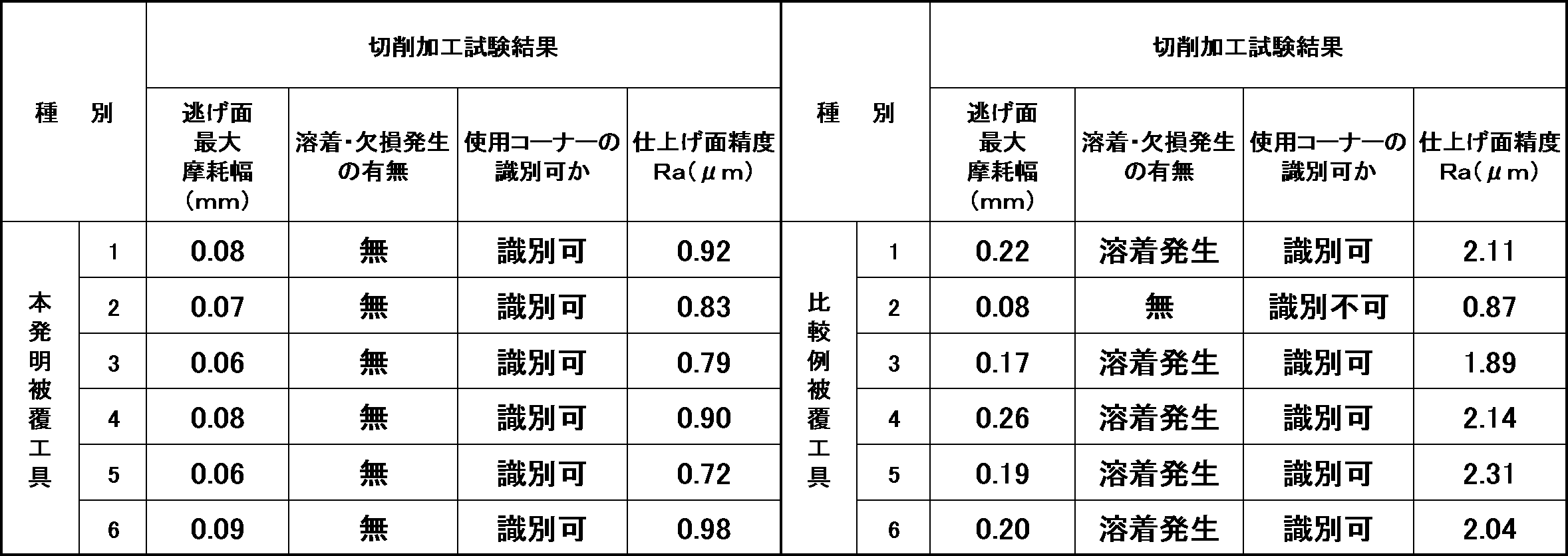
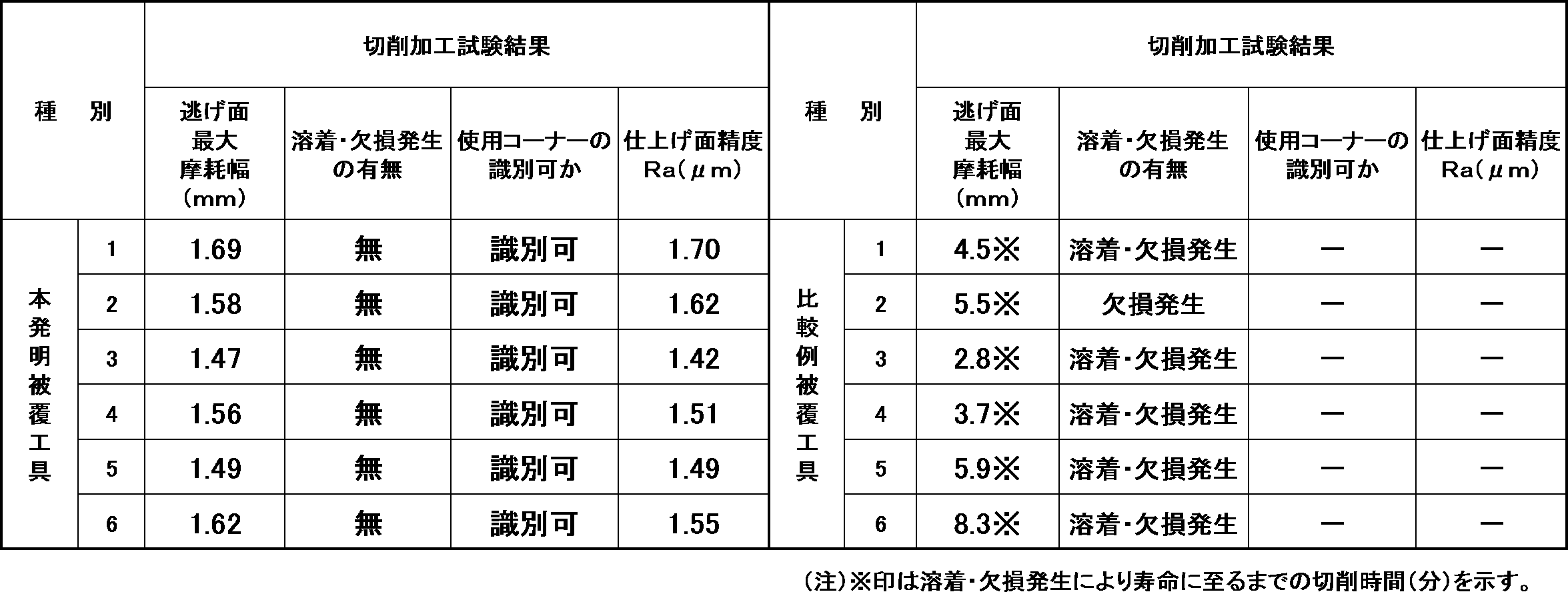
表5、8、9、10に示される結果から、本発明被覆工具は、すくい面および逃げ面ともに、表面平滑性を向上させることができ、その結果、耐溶着性や被削材の表面平滑性の向上が図られる。また、逃げ面最表面には、TiN相とAl2O3相との混合相あるいはTiNO相とAl2O3相との混合相が形成されているため、その色調変化によって、使用済コーナーと未使用コーナーの判別が容易であり、コーナー識別性にすぐれている。
さらに、高送り切削においては、すくい面のAl2O3層、TiCN層および逃げ面のAl2O3層とTiCN層は、ブラスト処理によって残留応力の緩和が図られるため、異常摩耗の発生による損傷を抑えることができる。
これに対して、比較例被覆工具においては、耐溶着性、耐チッピング性、耐欠損性にすぐれるものであってもコーナー識別性に劣り、また、コーナー識別性がすぐれるものにおいては、被削材の表面平滑性および耐異常摩耗性が劣るものであり、コーナー識別性と切削性能が両立するものはない。
さらに、高送り切削においては、すくい面のAl2O3層、TiCN層および逃げ面のAl2O3層とTiCN層は、ブラスト処理によって残留応力の緩和が図られるため、異常摩耗の発生による損傷を抑えることができる。
これに対して、比較例被覆工具においては、耐溶着性、耐チッピング性、耐欠損性にすぐれるものであってもコーナー識別性に劣り、また、コーナー識別性がすぐれるものにおいては、被削材の表面平滑性および耐異常摩耗性が劣るものであり、コーナー識別性と切削性能が両立するものはない。
上述のように、この発明の被覆工具は、切削性能にすぐれるとともにコーナー識別性にもすぐれることから、切削装置の高性能化並びに切削加工の省力化および省エネ化による低コスト化および高作業性を実現できるものである。
Claims (4)
- WC基超硬合金またはTiCN基サーメットからなる工具基体の表面に、少なくとも下部層と上部層とを含む硬質被覆層が形成されている表面被覆切削工具において、
(a)前記硬質被覆層の下部層は、TiC層、TiN層、TiCN層、TiCO層およびTiCNO層のうちの1層または2層以上からなり、
(b)前記表面被覆切削工具のすくい面には、前記下部層と、該下部層の表面に設けられた上部層のAl2O3層からなる硬質被覆層が形成されており、前記すくい面の表面粗さRaは0.25μm以下であり、
(c)前記表面被覆切削工具の逃げ面には、前記下部層と、該下部層の表面に設けられた上部層のAl2O3層からなる硬質被覆層が形成されており、前記Al2O3層の最表面に、TiN相とAl2O3相との混合相あるいはTiNO相とAl2O3相との混合相が形成されており、前記逃げ面の表面粗さRaは0.30μm以下であることを特徴とする表面被覆切削工具。 - 請求項1に記載の表面被覆切削工具において、前記混合相に占めるTiN相あるいはTiNO相の面積割合は、20~80面積%であることを特徴とする請求項1に記載の表面被覆切削工具。
- 請求項1または2に記載の表面被覆切削工具において、すくい面の上部層である前記Al2O3層の最表面には、5面積%以下のTiN相あるいはTiNO相が存在することを特徴とする請求項1または2に記載の表面被覆切削工具。
- 請求項1乃至3のいずれか一項に記載の表面被覆切削工具において、前記下部層として少なくとも1層のTiCN層が形成されており、すくい面のTiCN層は50~350MPaの引張残留応力を有し、逃げ面のTiCN層は400~600MPaの引張残留応力を有し、また、すくい面の前記Al2O3層は10~300MPaの引張残留応力を有し、逃げ面の前記Al2O3層は350~600MPaの引張残留応力を有することを特徴とする請求項1乃至3のいずれか一項に記載の表面被覆切削工具。
Applications Claiming Priority (2)
| Application Number | Priority Date | Filing Date | Title |
|---|---|---|---|
| JP2015-254536 | 2015-12-25 | ||
| JP2015254536A JP2017113860A (ja) | 2015-12-25 | 2015-12-25 | 表面被覆切削工具 |
Publications (1)
| Publication Number | Publication Date |
|---|---|
| WO2017110103A1 true WO2017110103A1 (ja) | 2017-06-29 |
Family
ID=59089937
Family Applications (1)
| Application Number | Title | Priority Date | Filing Date |
|---|---|---|---|
| PCT/JP2016/059356 Ceased WO2017110103A1 (ja) | 2015-12-25 | 2016-03-24 | 表面被覆切削工具 |
Country Status (2)
| Country | Link |
|---|---|
| JP (1) | JP2017113860A (ja) |
| WO (1) | WO2017110103A1 (ja) |
Families Citing this family (1)
| Publication number | Priority date | Publication date | Assignee | Title |
|---|---|---|---|---|
| WO2024247604A1 (ja) * | 2023-05-26 | 2024-12-05 | 京セラ株式会社 | 被覆工具及び切削工具 |
Citations (5)
| Publication number | Priority date | Publication date | Assignee | Title |
|---|---|---|---|---|
| WO2007049785A1 (ja) * | 2005-10-28 | 2007-05-03 | Kyocera Corporation | 表面被覆部材およびその製造方法、並びに切削工具 |
| JP2007125661A (ja) * | 2005-11-04 | 2007-05-24 | Mitsubishi Materials Corp | 硬質被覆層が高速切削加工ですぐれた耐チッピング性を発揮する穴なし表面被覆サーメット製切削スローアウエイチップ |
| JP2007331102A (ja) * | 2006-06-16 | 2007-12-27 | Sandvik Intellectual Property Ab | 被覆切削工具インサート |
| JP2009095907A (ja) * | 2007-10-15 | 2009-05-07 | Sumitomo Electric Hardmetal Corp | 刃先交換型切削チップ |
| JP2013522056A (ja) * | 2010-03-11 | 2013-06-13 | ケンナメタル インコーポレイテッド | コーティングされたpcbn切削インサート、かかるコーティングされたpcbn切削インサートを使用したコーティングされたpcbn切削工具、およびその作製方法 |
-
2015
- 2015-12-25 JP JP2015254536A patent/JP2017113860A/ja active Pending
-
2016
- 2016-03-24 WO PCT/JP2016/059356 patent/WO2017110103A1/ja not_active Ceased
Patent Citations (5)
| Publication number | Priority date | Publication date | Assignee | Title |
|---|---|---|---|---|
| WO2007049785A1 (ja) * | 2005-10-28 | 2007-05-03 | Kyocera Corporation | 表面被覆部材およびその製造方法、並びに切削工具 |
| JP2007125661A (ja) * | 2005-11-04 | 2007-05-24 | Mitsubishi Materials Corp | 硬質被覆層が高速切削加工ですぐれた耐チッピング性を発揮する穴なし表面被覆サーメット製切削スローアウエイチップ |
| JP2007331102A (ja) * | 2006-06-16 | 2007-12-27 | Sandvik Intellectual Property Ab | 被覆切削工具インサート |
| JP2009095907A (ja) * | 2007-10-15 | 2009-05-07 | Sumitomo Electric Hardmetal Corp | 刃先交換型切削チップ |
| JP2013522056A (ja) * | 2010-03-11 | 2013-06-13 | ケンナメタル インコーポレイテッド | コーティングされたpcbn切削インサート、かかるコーティングされたpcbn切削インサートを使用したコーティングされたpcbn切削工具、およびその作製方法 |
Also Published As
| Publication number | Publication date |
|---|---|
| JP2017113860A (ja) | 2017-06-29 |
Similar Documents
| Publication | Publication Date | Title |
|---|---|---|
| JP5872747B1 (ja) | 表面被覆切削工具 | |
| CN102625737B (zh) | 表面被覆切削工具 | |
| JP4739235B2 (ja) | 表面被覆切削工具 | |
| EP3360630B1 (en) | Surface-coated cutting tool | |
| EP3311939B1 (en) | Surface-coated cutting tool | |
| CN100484672C (zh) | 涂覆切削刀片 | |
| CN105705281B (zh) | 被覆切削工具 | |
| CN101090789B (zh) | 表面被覆切削工具 | |
| US9969007B2 (en) | Coated cutting tool | |
| KR20190024896A (ko) | Cvd 피복 절삭 공구 | |
| CN108778584B (zh) | 表面包覆切削工具 | |
| JPWO2007046299A1 (ja) | 刃先交換型切削チップ | |
| CN109562461B (zh) | 耐熔敷崩刀性及耐剥离性优异的表面包覆切削工具 | |
| JP2017042901A (ja) | 表面被覆切削工具 | |
| CN110637105A (zh) | 涂层切削工具 | |
| WO2019065678A1 (ja) | 耐溶着チッピング性にすぐれた表面被覆切削工具 | |
| JP2019063932A (ja) | 耐溶着チッピング性にすぐれた切削工具 | |
| WO2017110103A1 (ja) | 表面被覆切削工具 | |
| WO2017150533A1 (ja) | 硬質被覆層がすぐれた耐摩耗性と耐チッピング性を発揮する表面被覆切削工具およびその製造方法 | |
| JP2017177291A (ja) | 表面被覆切削工具の製造方法 | |
| JPH0569204A (ja) | 硬質層被覆炭化タングステン基超硬合金製切削工具 | |
| JP5088477B2 (ja) | 表面被覆切削工具 | |
| JP5094293B2 (ja) | 切削工具 | |
| JP2008137129A (ja) | 表面被覆切削工具 | |
| JP2008137130A (ja) | 表面被覆切削工具 |
Legal Events
| Date | Code | Title | Description |
|---|---|---|---|
| 121 | Ep: the epo has been informed by wipo that ep was designated in this application |
Ref document number: 16878006 Country of ref document: EP Kind code of ref document: A1 |
|
| NENP | Non-entry into the national phase |
Ref country code: DE |
|
| 122 | Ep: pct application non-entry in european phase |
Ref document number: 16878006 Country of ref document: EP Kind code of ref document: A1 |