WO2017109979A1 - 距離推定装置、距離推定方法及びプログラム - Google Patents
距離推定装置、距離推定方法及びプログラム Download PDFInfo
- Publication number
- WO2017109979A1 WO2017109979A1 PCT/JP2015/086350 JP2015086350W WO2017109979A1 WO 2017109979 A1 WO2017109979 A1 WO 2017109979A1 JP 2015086350 W JP2015086350 W JP 2015086350W WO 2017109979 A1 WO2017109979 A1 WO 2017109979A1
- Authority
- WO
- WIPO (PCT)
- Prior art keywords
- distance
- time
- feature
- moving
- moving body
- Prior art date
- Legal status (The legal status is an assumption and is not a legal conclusion. Google has not performed a legal analysis and makes no representation as to the accuracy of the status listed.)
- Ceased
Links
Images




Classifications
-
- G—PHYSICS
- G01—MEASURING; TESTING
- G01C—MEASURING DISTANCES, LEVELS OR BEARINGS; SURVEYING; NAVIGATION; GYROSCOPIC INSTRUMENTS; PHOTOGRAMMETRY OR VIDEOGRAMMETRY
- G01C22/00—Measuring distance traversed on the ground by vehicles, persons, animals or other moving solid bodies, e.g. using odometers, using pedometers
Definitions
- the present invention relates to a technique for estimating a moving distance of a moving object.
- Patent Document 1 discloses a method of correcting a vehicle speed sensor mounted on a moving body by estimating a moving distance of the moving body in a predetermined period.
- the correction device detects the number of output pulses of the vehicle speed sensor from the recognition of the feature A by the image recognition means to the recognition of the feature B, and the feature A and the feature B from the map information. To obtain the distance D. Then, the correction device corrects an arithmetic expression for obtaining the travel distance or travel speed of the vehicle from the output pulse number based on the relationship between the output pulse number and the distance D.
- An object of this invention is to estimate the moving distance of a moving body using arbitrary features.
- Invention of Claim 1 is a distance estimation apparatus, Comprising: The 1st acquisition part which each acquires the distance from the moving body to the feature in each of 1st time and 2nd time, and the said path
- Invention of Claim 7 is the distance estimation method performed by the distance estimation apparatus, Comprising: The 1st acquisition process which each acquires the distance from the moving body in each of 1st time and 2nd time, and the feature, Based on the second acquisition step of acquiring the distance from the path of the moving body to the feature, and the acquisition results of the first acquisition step and the second acquisition step, the first time to the second time. And a calculating step of calculating a moving distance of the moving body.
- the invention according to claim 8 is a program executed by a distance estimation device including a computer, and a first acquisition unit that acquires a distance from a moving object to a feature at each of a first time and a second time, The movement from the first time to the second time based on the acquisition results of the second acquisition unit, the first acquisition unit, and the second acquisition unit that acquire the distance from the route of the moving body to the feature
- the computer is caused to function as a calculation unit that calculates a movement distance of the body.
- An example of the positional relationship between one feature and a moving vehicle is shown.
- the other example of the positional relationship of one feature and a moving vehicle is shown.
- a perpendicular line from the feature position to the road is shown.
- the relationship between the lane center of the road data and the actual travel position is shown.
- It is a flowchart of the distance coefficient update process by an Example The relationship between travel speed and the number of pulses per unit time, and the relationship between travel speed and pulse width are shown.
- the distance estimation apparatus includes a first acquisition unit that acquires the distance from the moving object to the feature at each of the first time and the second time, and the feature from the path of the moving object.
- a second acquisition unit that acquires the distance to the calculation unit, and a calculation that calculates the moving distance of the moving body from the first time to the second time based on the acquisition results of the first acquisition unit and the second acquisition unit A section.
- the distance estimation apparatus acquires the distance from the moving object to the feature at each of the first time and the second time, and acquires the distance from the path of the moving object to the feature. And based on those acquisition results, the moving distance of the moving body from the first time to the second time is calculated. Thereby, the movement distance of a moving body is computable using the arbitrary features which can be measured from a moving body.
- the calculation unit includes a first distance that is a distance in a traveling direction of the moving body between the moving body and the feature at the first time, and the second time.
- the moving distance is calculated on the basis of a second distance that is a distance in the traveling direction of the moving body between the moving body and the feature.
- the calculation unit may calculate 1 of the vehicle speed pulse signal based on a moving distance from the first time to the second time and an average pulse width of the vehicle speed pulse signal. Calculate the travel distance per pulse. As a result, the vehicle speed pulse signal can be calibrated based on the calculated moving distance.
- the calculation unit calculates the movement distance when an angular velocity or a steering angle in a yaw direction of the moving body is less than a predetermined threshold. Thereby, the calculation accuracy of the movement distance can be improved.
- the calculation unit changes a time interval from the first time to the second time according to a traveling speed of the moving body.
- the calculation accuracy of the movement distance can be improved.
- the calculation unit shortens the time interval as the traveling speed of the moving body increases.
- the distance estimation method executed by the distance estimation device includes a first acquisition step of acquiring the distance from the moving object to the feature at each of the first time and the second time, Based on the second acquisition step of acquiring the distance from the path of the moving body to the feature, and the acquisition results of the first acquisition step and the second acquisition step, the first time to the second time. And a calculating step for calculating a moving distance of the moving body.
- a program executed by a distance estimation device including a computer acquires a distance from a moving object to a feature at each of a first time and a second time, The movement from the first time to the second time based on the acquisition results of the second acquisition unit, the first acquisition unit, and the second acquisition unit that acquire the distance from the route of the moving body to the feature
- the computer is caused to function as a calculation unit that calculates a movement distance of the body.
- the movement distance of a moving body is computable using the arbitrary features which can be measured from a moving body.
- the above program can be stored in a storage medium and used.
- the vehicle speed is detected using a vehicle speed sensor, and the traveling state is detected using an angular velocity sensor or a steering angle sensor, thereby measuring the movement state of the vehicle. Then, the current position is estimated by integrating these with information measured by the GPS or the external sensor. Therefore, in order to improve the self-position estimation accuracy, it is required to detect the vehicle speed with high accuracy.
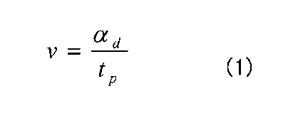
- the vehicle speed sensor outputs a vehicle speed pulse signal at a time interval proportional to the output shaft of the transmission or the rotational speed of the wheels, for example. Then, as shown in the following formula (1), the distance coefficient alpha d can be calculated vehicle speed v by dividing a pulse width t p. This distance coefficient ⁇ d is the moving distance per pulse of the vehicle speed pulse signal.
- the moving distance per pulse varies depending on the vehicle type. Further, when the outer diameter of the tire changes due to a change in tire air pressure or tire replacement, the moving distance per pulse also changes. Furthermore, the moving distance per pulse varies depending on the traveling speed. Usually, the running resistance causes a difference between the wheel speed obtained from the vehicle speed pulse and the actual vehicle speed. Since the running resistance is higher during high speed running than during low speed running, the speed difference between the wheel speed and the vehicle body speed is also greater during high speed running than during low speed running. Therefore, the moving distance per pulse differs between high speed traveling and low speed traveling. As described above, in order to obtain the vehicle speed with high accuracy, the distance coefficient needs to be appropriately calibrated and updated.
- the GPS information itself which is a reference, may include a large error.
- the conditions should be strict, but the more strict the conditions, the less the number of times reference information is acquired, and the conflicting problem that the progress of calibration becomes slow. Comes out.
- the distance coefficient updating apparatus does not use GPS information as a reference, but based on the measurement of a feature by an external sensor, the moving distance of the vehicle Is used as a reference for calibration of the vehicle speed pulse signal.
- an external sensor a camera, LiDAR (Light Detection And Ranging), a millimeter wave radar, or the like can be used.
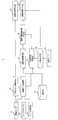
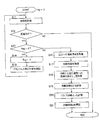
- FIG. 1 is a flowchart illustrating distance coefficient update processing according to the embodiment.
- the update device at time T 1, to measure one feature using external sensors.
- step P2 updating device, at time T 2, which has passed ⁇ T seconds from the time T 1, to measure the same feature as that measured at time T 1.
- the update device acquires the length L of the perpendicular line from the feature position to the road on which the vehicle is traveling (hereinafter referred to as “traveling road”) using the map data. Then, in step P4, the update device was acquired at time T 1 and time T 2, the distance from the vehicle center position to feature at each time, and the length of a perpendicular to the vehicle travel road from the feature position Using this, the travel distance ⁇ D of the vehicle from time T 1 to time T 2 is calculated.
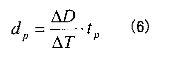
- step P5 the update device, an average pulse width t p of the vehicle speed pulse signal from the time T 1 of the time T 2, the elapsed time ⁇ T from the time T 1 to time T 2, determined in step P4
- the moving distance d p per pulse is calculated using the moving distance ⁇ D of the vehicle from time T 1 to time T 2 .
- step P6 the updating device updates the distance coefficient ⁇ d using the movement distance d p per pulse obtained in step P5.
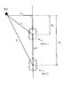
- FIG. 2 shows an example of the positional relationship between one feature and a moving vehicle. Vehicle during the period from the time T 1 time T 2, is to have moved as shown in FIG. First, the update device detects the feature at time T 1, to obtain the distance L 1 from the vehicle to the feature (step P1).
- the update device detects the feature at time T 2 as well as time T 1 and acquires the distance L 2 from the vehicle to the feature (step P2).
- the update device by using the map data, and acquires the length L m of a perpendicular to the vehicle travel road from the feature position. This will be described in detail later.
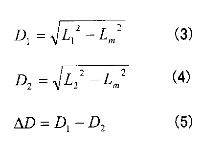
- the update device uses the distance L 1 acquired at time T 1 , the distance L 2 acquired at time T 2 , and the length L m of the perpendicular from the feature position to the traveling road to calculates a moving distance ⁇ D the vehicle from 1 to time T 2.
- the distance between the vehicle position and the feature position at the time T 1 in the traveling direction of the vehicle is D 1
- the vehicle position and the feature at the time T 2 is obtained as follows.
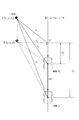
- FIG. 3 shows a calculation method of the moving distance ⁇ D of the vehicle when the three-dimensional position of the feature can be acquired using an external sensor capable of three-dimensional measurement.
- the moving distance ⁇ D of the vehicle can be calculated by the equations (3) to (5).
- Figure 4 is a diagram for explaining the average pulse width t p.
- Average pulse width t p is the pulse width measured between the time T 1 of the time T 2, leave buffers can be calculated by taking the average as the following equation (7).
- the average pulse width can also be obtained by sequential calculation using Equation (8).
- the average pulse width is obtained by sequential calculation, it is not necessary to buffer the measured pulse width, so that the amount of memory used in the apparatus can be reduced.
- FIG. 5 is a flowchart of processing for obtaining the average pulse width by sequential calculation.
- the update unit resets the coefficient k indicating the number of detected pulses to "0" (step S51), and acquires the current time T (step S52).
- the update unit determines whether the present time T reaches time T 2 (step S53).
- the update device by the equation (7), obtained by dividing the difference between the average pulse width t p and the current pulse width t k at the time by a factor k value (t k -t p) / k , that is, to update the current pulse width t k average pulse t p the variation of adding the average pulse width t p of the time average pulse width t p by, step S52 Return to.
- step S53 if the current time T reaches time T 2 (step S53: YES), the process ends.
- the update device updates the distance coefficient ⁇ d using the movement distance d p obtained in step P5. Specifically, the obtained moving distance d p is set as a new distance coefficient ⁇ d .
- the updated distance coefficient ⁇ d obtained in this way is used for calculation of the vehicle speed v by the equation (1).
- FIG. 6 shows the positional relationship between the feature position and road data indicating the road on which the vehicle is traveling.
- the feature position on the map be a point P (x 1 , y 1 ).
- the straight line Rd can be calculated from the position coordinates of the nodes before and after the road data.
- the intersection of the perpendicular line drawn from the point P indicating the feature position to the straight line Rd and the straight line Rd is defined as a point H (x 2 , y 2 ).
- the length of the perpendicular PH can be calculated as follows.
- the length L m of the perpendicular line PH is from the three square theorem
- the length of the perpendicular PH L m is as follows.
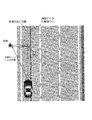
- FIG. 7 shows the positional relationship between the actual traveling position of the vehicle and the road data on the map. It is assumed that the road data in the map includes position information of the center line of the lane. The vehicle does not always travel in the center of the lane, and in many cases, the vehicle actually travels at a position deviated from the center of the lane. If the travel distance of the vehicle is calculated using the road data in the map and the measurement results from the external sensors, the difference between the road data in the map and the actual vehicle travel position will affect the error, and the accuracy will deteriorate. Conceivable.
- ⁇ L m the length L m in the calculation of the movement distance ⁇ D in the process P4
- the deviation amount [Delta] L m for example using a camera or LiDAR detects white lines on both sides of the vehicle, the vehicle can be determined by recognizing whether running anywhere in the lane by using the detection result .
- FIG. 8 is a block diagram illustrating the configuration of the update device 1 according to the embodiment.
- the updating device 1 obtains the movement distance ⁇ D based on the measurement result of one feature by the external sensor and the length L m of the perpendicular drawn from the feature position to the traveling road.
- the updating device 1 includes a gyro sensor 10, a vehicle speed sensor 11, a GPS receiver 12, an external sensor 13, a map database (hereinafter referred to as "map DB") 14, and an average pulse width acquisition.
- Unit 15 distance coefficient calibration unit 16, own vehicle position acquisition unit 17, road information acquisition unit 18, feature-road distance calculation unit 19, movement distance calculation unit 20, feature information acquisition unit 21, And a feature measurement unit 22.
- the average pulse width acquisition unit 15, the distance coefficient calibration unit 16, the own vehicle position acquisition unit 17, the road information acquisition unit 18, the feature-road distance calculation unit 19, the movement distance calculation unit 20, the feature information acquisition unit 21, And the feature measurement part 22 is realizable when computers, such as CPU, run the program prepared beforehand.
- Average pulse width obtaining unit 15 obtains the average pulse width t p on the basis of the vehicle speed pulse signal a vehicle speed sensor 11 outputs, and outputs to the distance factor correcting unit 16.
- the vehicle position acquisition unit 17 acquires the vehicle position of the vehicle based on the outputs of the gyro sensor 10, the vehicle speed sensor 11, and the GPS receiver 12, and outputs the vehicle position to the road information acquisition unit 18 and the feature information acquisition unit 21.
- the external sensor 13 detects the feature and sends the detection result to the feature measuring unit 22.
- the feature measurement unit 22 measures the distance L from the vehicle to the feature and outputs the distance L to the movement distance calculation unit 20 and the feature information acquisition unit 21.
- the feature information acquisition unit 21 refers to the map DB 14 and based on the own vehicle position input from the own vehicle position acquisition unit 17 and the distance L to the feature input from the feature measurement unit 22.
- the object position (x 1 , y 1 ) is acquired and output to the feature-road distance calculation unit 19.
- Feature - the road distance calculating unit 19 based on the straight line Rd indicating the road that is input from the road information acquisition unit 18, the feature position input from the feature information acquiring unit 21 and the (x 1, y 1) Then, the length L m of the perpendicular line drawn from the feature position to the traveling road is calculated and output to the movement distance calculation unit 20.
- the movement distance calculation unit 20 includes a distance L (L 1 , L 2 ) to the feature input from the feature measurement unit 22 and a perpendicular length L m input from the feature-road distance calculation unit 19. Based on the above, the movement distance ⁇ D is calculated by the equations (3) to (5) and output to the distance coefficient calibration unit 16.
- the moving distance per pulse d p ( That is, the distance coefficient ⁇ d ) is calculated.
- the vehicle body speed may be calculated from the obtained movement distance per pulse.
- FIG. 9 is a flowchart of the distance coefficient update process according to the embodiment.
- the updating device 1 measures a feature using the external sensor 13 and acquires a distance L from the vehicle to the feature (step S11).
- the update device 1 determines whether or not the vehicle is traveling straight on the basis of the vehicle position output by the vehicle position acquisition unit 17 (step S11). This is because the accuracy of the movement distance ⁇ D output by the movement distance calculation unit 20 decreases when the vehicle is not traveling straight ahead.
- the gyro sensor 10 can detect the angular velocity ⁇ in the yaw direction of the vehicle, it may be determined that the vehicle is traveling straight when
- the steering angle ⁇ of the vehicle it may be determined that the vehicle is traveling straight when
- step S13: NO the updating device 1 acquires the road information that is being traveled by the road information acquisition unit 18 (step S16), and acquires the feature information by the feature information acquisition unit 21. (Step S17).
- the updating device 1 calculates the length Lm of the perpendicular from the feature to the traveling road by the feature-road distance calculation unit 19 (step S18), and calculates the movement distance ⁇ D by the movement distance calculation unit 20 (Step S19).
- the updating apparatus 1 uses the moving distance ⁇ D calculates the moving distance d p per pulse (step S20), and updates the distance coefficient alpha d (step S21). Then, the process ends.
- the movement distance d p per pulse obtained in the above-described distance coefficient update process is an average value of the movement distance per pulse during the time interval ⁇ T from time T 1 to time T 2 . Therefore, the large variation of the pulse width of the time interval [Delta] T, the accuracy of the moving distance d p which is calculated is deteriorated. Therefore, it is desirable that the number of pulses during the time interval ⁇ T is as small as possible.
- the number of pulses per unit time varies depending on the running speed of the vehicle. For example, consider the number of pulses per second as shown in FIG. In a vehicle type that outputs two pulses per tire rotation, the number of pulses per second is 3 pulses at 10 km / h, 17 pulses at 50 km / h, and 35 pulses at 100 km / h, and there is a large difference depending on the running speed.
- FIG. 9B shows the relationship between the traveling speed and the pulse width.
- ⁇ T 300 ms when the traveling speed is less than 20 km / h
- ⁇ T 200 ms when the speed is 20 km / h or more and less than 30 km / h.
- the number of pulses that can be measured during the time interval ⁇ T is about 1 pulse or 2 pulses, and the moving distance is high.
- d p can be calculated.
- the distance coefficient is basically updated when the vehicle is traveling straight ahead.
- the movement distance ⁇ D obtained in the process P4 is not an actual movement distance but an approximate value.
- the time interval ⁇ T is too large, the difference between the actual moving distance and the moving distance calculated in the process P4 becomes large. From this point of view, it is desirable to make the time interval ⁇ T from time T 1 to time T 2 as small as possible.
- Modification 3 If the external sensor is attached to a low position of the vehicle, it is considered that the occlusion increases by surrounding vehicles, and the frequency with which a suitable feature for updating the distance coefficient can be detected decreases. Therefore, it is preferable to install the external sensor so that the upper side can be measured above the height of the surrounding vehicle. Thereby, since the detection frequency of the feature increases and the number of updates of the distance coefficient increases, the accuracy of the distance coefficient can be improved.
- the present invention can be used for an apparatus mounted on a moving body.
Landscapes
- Physics & Mathematics (AREA)
- Engineering & Computer Science (AREA)
- General Physics & Mathematics (AREA)
- Radar, Positioning & Navigation (AREA)
- Remote Sensing (AREA)
- Navigation (AREA)
Abstract
距離推定装置は、第1時刻及び第2時刻それぞれにおける移動体から地物までの距離をそれぞれ取得するとともに、移動体の経路から地物までの距離を取得する。そして、それらの取得結果に基づき、第1時刻から第2時刻までの前記移動体の移動距離を算出する。
Description
本発明は、移動体の移動距離を推定する技術に関する。
移動体の所定期間における移動距離を推定することにより、移動体に搭載された車速センサを補正する手法が例えば特許文献1に記載されている。特許文献1では、補正装置は、画像認識手段により地物Aを認識してから地物Bを認識するまでの車速センサの出力パルス数を検出するとともに、地図情報から地物Aと地物Bとの距離Dを取得する。そして、補正装置は、出力パルス数と距離Dとの関係に基づいて、出力パルス数から車両の走行距離又は走行速度を求める演算式を補正する。
しかし、特許文献1の方法では、画像認識手段により一度に1つの地物しか認識できず、道路に描かれた標識のように、車両が走行している道路上の地物しか利用することができない。
本発明が解決しようとする課題としては、上記のものが例として挙げられる。本発明は、任意の地物を利用して移動体の移動距離を推定することを目的とする。
請求項1に記載の発明は、距離推定装置であって、第1時刻及び第2時刻それぞれにおける移動体から地物までの距離をそれぞれ取得する第1取得部と、前記移動体の経路から前記地物までの距離を取得する第2取得部と、前記第1取得部及び前記第2取得部の取得結果に基づき、前記第1時刻から前記第2時刻までの前記移動体の移動距離を算出する算出部と、を備えることを特徴とする。
請求項7に記載の発明は、距離推定装置により実行される距離推定方法であって、第1時刻及び第2時刻それぞれにおける移動体から地物までの距離をそれぞれ取得する第1取得工程と、前記移動体の経路から前記地物までの距離を取得する第2取得工程と、前記第1取得工程及び前記第2取得工程の取得結果に基づき、前記第1時刻から前記第2時刻までの前記移動体の移動距離を算出する算出工程と、を備えることを特徴とする。
請求項8に記載の発明は、コンピュータを備える距離推定装置によって実行されるプログラムであって、第1時刻及び第2時刻それぞれにおける移動体から地物までの距離をそれぞれ取得する第1取得部、前記移動体の経路から前記地物までの距離を取得する第2取得部、前記第1取得部及び前記第2取得部の取得結果に基づき、前記第1時刻から前記第2時刻までの前記移動体の移動距離を算出する算出部、として前記コンピュータを機能させることを特徴とする。
本発明の好適な実施形態では、距離推定装置は、第1時刻及び第2時刻それぞれにおける移動体から地物までの距離をそれぞれ取得する第1取得部と、前記移動体の経路から前記地物までの距離を取得する第2取得部と、前記第1取得部及び前記第2取得部の取得結果に基づき、前記第1時刻から前記第2時刻までの前記移動体の移動距離を算出する算出部と、を備える。
上記の距離推定装置は、第1時刻及び第2時刻それぞれにおける移動体から地物までの距離をそれぞれ取得するとともに、移動体の経路から地物までの距離を取得する。そして、それらの取得結果に基づき、第1時刻から第2時刻までの前記移動体の移動距離を算出する。これにより、移動体から計測できる任意の地物を利用して、移動体の移動距離を算出することができる。
上記の距離推定装置の一態様では、前記算出部は、前記第1時刻における前記移動体と前記地物との間の前記移動体の進行方向における距離である第1距離と、前記第2時刻における前記移動体と前記地物との間の前記移動体の進行方向における距離である第2距離と、に基づいて、前記移動距離を算出する。
上記の距離推定装置の他の一態様では、前記算出部は、前記第1時刻から前記第2時刻までの移動距離と、車速パルス信号の平均パルス幅とに基づいて、前記車速パルス信号の1パルスあたりの移動距離を算出する。これにより、算出した移動距離に基づいて、車速パルス信号のキャリブレーションなどを行うことができる。
上記の距離推定装置の他の一態様では、前記算出部は、前記移動体のヨー方向の角速度又は操舵角が所定の閾値未満であるときに前記移動距離を算出する。これにより、移動距離の算出精度を向上させることができる。
上記の距離推定装置の他の一態様では、前記算出部は、前記移動体の走行速度に応じて、前記第1時刻から前記第2時刻までの時間間隔を変化させる。これにより、移動距離の算出精度を向上させることができる。好適には、前記算出部は、前記移動体の走行速度が速いほど前記時間間隔を短くする。
本発明の他の好適な実施形態では、距離推定装置により実行される距離推定方法は、第1時刻及び第2時刻それぞれにおける移動体から地物までの距離をそれぞれ取得する第1取得工程と、前記移動体の経路から前記地物までの距離を取得する第2取得工程と、前記第1取得工程及び前記第2取得工程の取得結果に基づき、前記第1時刻から前記第2時刻までの前記移動体の移動距離を算出する算出工程と、を備える。これにより、移動体から計測できる任意の地物を利用して、移動体の移動距離を算出することができる。
本発明の他の好適な実施形態では、コンピュータを備える距離推定装置によって実行されるプログラムは、第1時刻及び第2時刻それぞれにおける移動体から地物までの距離をそれぞれ取得する第1取得部、前記移動体の経路から前記地物までの距離を取得する第2取得部、前記第1取得部及び前記第2取得部の取得結果に基づき、前記第1時刻から前記第2時刻までの前記移動体の移動距離を算出する算出部、として前記コンピュータを機能させる。これにより、移動体から計測できる任意の地物を利用して、移動体の移動距離を算出することができる。上記のプログラムは、記憶媒体に記憶して利用することができる。
以下、図面を参照して本発明の好適な実施例について説明する。以下では、本発明の距離推定手法により得られた移動体の移動距離を、車両の車速パルスのキャリブレーションに使用する実施例について説明する。
[背景]
現在のカーナビゲーション装置などに搭載されている自己位置推定システムでは、車速センサを用いて車速を検出し、角速度センサあるいは操舵角センサを用いて進行方向を検出することで、車両の移動状況を計測し、これらをGPSや外界センサで計測した情報と統合することで現在位置を推定している。よって、自己位置推定精度を向上させるために、車速を高精度に検出することが求められている。
現在のカーナビゲーション装置などに搭載されている自己位置推定システムでは、車速センサを用いて車速を検出し、角速度センサあるいは操舵角センサを用いて進行方向を検出することで、車両の移動状況を計測し、これらをGPSや外界センサで計測した情報と統合することで現在位置を推定している。よって、自己位置推定精度を向上させるために、車速を高精度に検出することが求められている。
車速センサは、例えば、トランスミッションの出力軸または車輪の回転速度に比例した時間間隔で車速パルス信号を出力する。そして、下記の式(1)に示すように、距離係数αdをパルス幅tpで除することで車速vを計算できる。この距離係数αdは車速パルス信号の1パルスあたりの移動距離である。
従来は、距離係数のキャリブレーションを行う際に、リファレンスとしてGPSから得られる情報を利用してきた。例えば、GPSから得られるGPS位置によって求まる車両の移動距離ΔDと車速パルス数nを用いて、下記の式(2)により1パルスあたりの移動距離dpを算出し、常時、平均化処理を施すことにより補正を行うという方法がある。

[距離係数更新処理]
以上の観点より、本実施例に係る距離係数更新装置(以下、単に「更新装置」とも呼ぶ。)は、GPS情報をリファレンスとせずに、外界センサによる地物の計測に基づいて車両の移動距離を計算し、車速パルス信号のキャリブレーションのリファレンスとして使用する。外界センサとしては、カメラやLiDAR(Light Detection And Ranging)、ミリ波レーダーなどを用いることができる。
以上の観点より、本実施例に係る距離係数更新装置(以下、単に「更新装置」とも呼ぶ。)は、GPS情報をリファレンスとせずに、外界センサによる地物の計測に基づいて車両の移動距離を計算し、車速パルス信号のキャリブレーションのリファレンスとして使用する。外界センサとしては、カメラやLiDAR(Light Detection And Ranging)、ミリ波レーダーなどを用いることができる。
図1は、実施例に係る距離係数更新処理を示すフローチャートである。まず、工程P1では、更新装置は、時刻T1において、外界センサを用いて1つの地物を計測する。次に、工程P2では、更新装置は、時刻T1からΔT秒経過した時刻T2において、時刻T1で計測したものと同じ地物を計測する。
次に、工程P3では、更新装置は、地図データを用いて、地物位置から車両が走行している道路(以下、「走行道路」と呼ぶ。)への垂線の長さLを取得する。そして、工程P4では、更新装置は、時刻T1及び時刻T2で取得した、各時刻における車両中心位置から地物までの距離と、地物位置から車両の走行道路への垂線の長さとを用いて、時刻T1から時刻T2までの車両の移動距離ΔDを算出する。
次に、工程P5では、更新装置は、時刻T1から時刻T2の間の車速パルス信号の平均パルス幅tpと、時刻T1から時刻T2までの経過時間ΔTと、工程P4で求めた時刻T1から時刻T2までの車両の移動距離ΔDとを用いて、1パルスあたりの移動距離dpを算出する。そして、工程P6では、更新装置は、工程P5で求めた1パルスあたりの移動距離dpを用いて、距離係数αdを更新する。
次に、上記の距離係数更新処理の各工程について詳しく説明する。
(1)地物の計測(工程P1~P2)
図2は、1つの地物と移動中の車両との位置関係の一例を示す。時刻T1から時刻T2の間に車両が図2に示すように移動したとする。まず、更新装置は、時刻T1において地物を検出し、車両から地物までの距離L1を取得する(工程P1)。
図2は、1つの地物と移動中の車両との位置関係の一例を示す。時刻T1から時刻T2の間に車両が図2に示すように移動したとする。まず、更新装置は、時刻T1において地物を検出し、車両から地物までの距離L1を取得する(工程P1)。
次に、更新装置は、時刻T2においても時刻T1と同様に地物を検出し、車両から地物までの距離L2を取得する(工程P2)。
(2)走行道路への垂線の長さの取得
次に、更新装置は、地図データを用いて、地物位置から車両の走行道路への垂線の長さLmを取得する。これについては、後に詳しく説明する。
次に、更新装置は、地図データを用いて、地物位置から車両の走行道路への垂線の長さLmを取得する。これについては、後に詳しく説明する。
(3)移動距離ΔDの算出(工程P4)
次に、更新装置は、時刻T1で取得した距離L1と、時刻T2で取得した距離L2と、地物位置から走行道路への垂線の長さLmとを用いて、時刻T1から時刻T2までの車両の移動距離ΔDを算出する。具体的に、図2において、時刻T1における車両位置と地物位置との車両の進行方向における距離(即ち、走行道路に沿った距離)をD1とし、時刻T2における車両位置と地物位置との車両の進行方向における距離をD2とすると、車両の移動距離ΔDは以下のように得られる。
次に、更新装置は、時刻T1で取得した距離L1と、時刻T2で取得した距離L2と、地物位置から走行道路への垂線の長さLmとを用いて、時刻T1から時刻T2までの車両の移動距離ΔDを算出する。具体的に、図2において、時刻T1における車両位置と地物位置との車両の進行方向における距離(即ち、走行道路に沿った距離)をD1とし、時刻T2における車両位置と地物位置との車両の進行方向における距離をD2とすると、車両の移動距離ΔDは以下のように得られる。
(4)1パルスあたりの移動距離dpの計算(工程P5)
次に、更新装置は、時刻T1から時刻T2までのΔT秒間における車両の移動距離ΔDと、車速パルス信号の平均パルス幅tpとを用いて、以下のように、1パルスあたりの移動距離dpを算出する。
次に、更新装置は、時刻T1から時刻T2までのΔT秒間における車両の移動距離ΔDと、車速パルス信号の平均パルス幅tpとを用いて、以下のように、1パルスあたりの移動距離dpを算出する。


現在時刻Tが時刻T2になっていない場合(ステップS53:NO)、更新装置は車速パルス信号を検出し、そのパルス幅tkを取得する(ステップS54)。次に、更新装置は、係数kを1増加させ(ステップS55)、係数k=1であるか否かを判定する(ステップS56)。
係数k=1である場合(ステップS56:YES)、そのパルス幅tkを平均パルス幅tpに代入し(ステップS58)、ステップS52へ戻る。一方、係数k=1でない場合(ステップS56:NO)、更新装置は、式(7)により、その時点における平均パルス幅tpと今回のパルス幅tkとの差分を係数kで除した値(tk-tp)/k、即ち、今回のパルス幅tkによる平均パルスtpの変動分をその時点の平均パルス幅tpに加算して平均パルス幅tpを更新し、ステップS52へ戻る。そして、ステップS53において、現在時刻Tが時刻T2になった場合(ステップS53:YES)、処理は終了する。
(5)距離係数αdの更新(工程P6)
次に、更新装置は、工程P5で得られた移動距離dpを用いて、距離係数αdを更新する。具体的には、得られた移動距離dpを新たな距離係数αdとする。なお、こうして得られた更新後の距離係数αdは、式(1)による車速vの算出などに使用される。
次に、更新装置は、工程P5で得られた移動距離dpを用いて、距離係数αdを更新する。具体的には、得られた移動距離dpを新たな距離係数αdとする。なお、こうして得られた更新後の距離係数αdは、式(1)による車速vの算出などに使用される。
(6)地物位置から走行道路への垂線の長さLmの計算方法
地物位置から走行道路への垂線の長さLmを求めるためには、(A)車両がどの道路を走行しているか、(B)車両が車線のどこを走行しているか(特に車線の幅方向の位置)、の情報が必要となる。このうち、(A)は、カーナビゲーション機器に実装されているような、既存の自己位置推定技術により取得することができる。一方、(B)の精度が算出される移動距離ΔDの精度に影響する。(B)が正確にわからない場合でも、車両が車線の中央を走行していると仮定することで垂線の長さLmを計算することができるが、移動距離ΔDの誤差が大きくなる可能性がある。これに関しては、長さLmの補正方法について後述する。
地物位置から走行道路への垂線の長さLmを求めるためには、(A)車両がどの道路を走行しているか、(B)車両が車線のどこを走行しているか(特に車線の幅方向の位置)、の情報が必要となる。このうち、(A)は、カーナビゲーション機器に実装されているような、既存の自己位置推定技術により取得することができる。一方、(B)の精度が算出される移動距離ΔDの精度に影響する。(B)が正確にわからない場合でも、車両が車線の中央を走行していると仮定することで垂線の長さLmを計算することができるが、移動距離ΔDの誤差が大きくなる可能性がある。これに関しては、長さLmの補正方法について後述する。
図6は、地物位置と、車両の走行道路を示す道路データとの位置関係を示す。いま、地図上の地物位置を点P(x1、y1)とする。地図上に、道路データが直線Rd:ax+by+c=0として定義されているとする。なお、直線Rdは、道路データの前後のノードの位置座標から算出することができる。
図6において、地物位置を示す点Pから直線Rdへ下ろした垂線と、直線Rdとの交点を点H(x2、y2)とする。このとき、垂線PHの長さは以下のように計算することができる。
まず、直線Rdと垂線PHは直交するので、

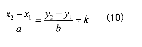

点Hは直線Rd上の点なので、

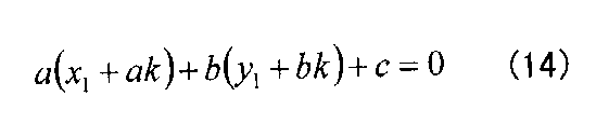
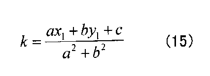

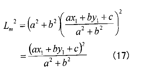
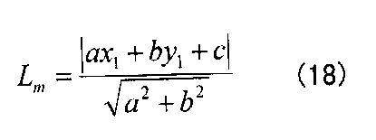
また、図3を参照して説明したように、地物の3次元位置を取得できる場合、地物位置がP(x1、y1、z1)で与えられるとすると、垂線PHの長さLmは以下のようになる。
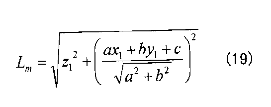
[実施例]
次に、上記の更新装置の実施例について説明する。図8は、実施例に係る更新装置1の構成を示すブロック図である。この実施例では、更新装置1は、外界センサによる1つの地物の計測結果と、地物位置から走行道路に下ろした垂線の長さLmとに基づいて、移動距離ΔDを求める。
次に、上記の更新装置の実施例について説明する。図8は、実施例に係る更新装置1の構成を示すブロック図である。この実施例では、更新装置1は、外界センサによる1つの地物の計測結果と、地物位置から走行道路に下ろした垂線の長さLmとに基づいて、移動距離ΔDを求める。
図示のように、更新装置1は、ジャイロセンサ10と、車速センサ11と、GPS受信機12と、外界センサ13と、地図データベース(以下、「地図DB」と記す)14と、平均パルス幅取得部15と、距離係数校正部16と、自車位置取得部17と、道路情報取得部18と、地物-道路距離計算部19と、移動距離計算部20と、地物情報取得部21と、地物計測部22とを備える。なお、平均パルス幅取得部15、距離係数校正部16、自車位置取得部17、道路情報取得部18、地物-道路距離計算部19、移動距離計算部20、地物情報取得部21、及び、地物計測部22は、CPUなどのコンピュータが予め用意されたプログラムを実行することにより実現することができる。
平均パルス幅取得部15は、車速センサ11が出力する車速パルス信号に基づいて平均パルス幅tpを取得し、距離係数校正部16へ出力する。
自車位置取得部17は、ジャイロセンサ10、車速センサ11及びGPS受信機12の出力に基づいて車両の自車位置を取得し、道路情報取得部18及び地物情報取得部21へ出力する。道路情報取得部18は、自車位置取得部17から入力された自車位置に基づいて地図DB14を参照し、走行道路の道路情報を取得する。具体的には、道路情報取得部18は、走行道路に相当するリンクの端点の位置を地図DB14から取得し、その道路を示す直線Rd:ax+by+c=0を求めて地物-道路間距離計算部19へ供給する。
外界センサ13は地物を検出し、検出結果を地物計測部22へ送る。地物計測部22は、車両から地物までの距離Lを計測し、移動距離計算部20及び地物情報取得部21へ出力する。地物情報取得部21は、地図DB14を参照し、自車位置取得部17から入力された自車位置と、地物計測部22から入力された地物までの距離Lとに基づいて、地物位置(x1、y1)を取得して地物-道路間距離計算部19へ出力する。
地物-道路距離計算部19は、道路情報取得部18から入力された道路を示す直線Rdと、地物情報取得部21から入力された地物位置(x1、y1)とに基づいて、地物位置から走行道路へ下ろした垂線の長さLmを計算し、移動距離計算部20へ出力する。
移動距離計算部20は、地物計測部22から入力された地物までの距離L(L1、L2)と、地物-道路距離計算部19から入力された垂線の長さLmとに基づいて、式(3)~(5)により移動距離ΔDを計算し、距離係数校正部16へ出力する。
距離係数校正部16は、平均パルス幅取得部15から入力された平均パルス幅tpと、移動距離計算部20から入力された移動距離ΔDとに基づいて、1パルスあたりの移動距離dp(即ち、距離係数αd)を算出する。求めた1パルスあたりの移動距離から、車体速度を算出してもよい。
次に、実施例による距離係数更新処理について説明する。図9は、実施例による距離係数更新処理のフローチャートである。
まず、更新装置1は、外界センサ13を用いて地物を計測し、車両からその地物までの距離Lを取得する(ステップS11)。次に、更新装置1は、自車位置取得部17が出力する自車位置などに基づいて、車両が直進走行しているが否かを判定する(ステップS11)。これは、車両が直進走行していない場合は、移動距離計算部20が出力する移動距離ΔDの精度が低下するからである。具体的に、ジャイロセンサ10が車両のヨー方向の角速度ωを検出できる場合には、|ω|<Δω(Δω:所定の閾値)の場合に車両が直進走行していると判定してもよい。また、車両の操舵角δを検出できる場合には、|δ|<Δδ(Δδ:所定の閾値)の場合に車両が直進走行していると判定してもよい。
車両が直進走行していない場合(ステップS12:NO)、処理は終了する。一方、車両が直進走行している場合(ステップS12:YES)、更新装置1は、flag=0であるか否かを判定する(ステップS13)。なお、「flag」は、処理の開始時に「0」にリセットされている。flag=0である場合(ステップS13:YES)、更新装置1はflagに「1」をセットし(ステップS14)、平均パルス幅tpの計算を開始して(ステップS15)、ステップS11へ戻る。
一方、flag=0でない場合(ステップS13:NO)、更新装置1は、道路情報取得部18により走行中の道路情報を取得し(ステップS16)、地物情報取得部21により地物情報を取得する(ステップS17)。次に、更新装置1は、地物-道路間距離計算部19により地物から走行中道路への垂線の長さLmを計算し(ステップS18)、移動距離計算部20により移動距離ΔDを算出する(ステップS19)。そして、更新装置1は、移動距離ΔDを用いて1パルスあたりの移動距離dpを算出し(ステップS20)、距離係数αdを更新する(ステップS21)。そして、処理を終了する。
[地物計測周期]
上記の距離係数更新処理において求められる1パルスあたりの移動距離dpは、時刻T1から時刻T2までの時間間隔ΔTの間の1パルスあたりの移動距離の平均値である。そのため、時間間隔ΔTの間のパルス幅の変動が大きいと、算出される移動距離dpの精度が悪化する。従って、時間間隔ΔTの間のパルス数はできるだけ少ないことが望ましい。
上記の距離係数更新処理において求められる1パルスあたりの移動距離dpは、時刻T1から時刻T2までの時間間隔ΔTの間の1パルスあたりの移動距離の平均値である。そのため、時間間隔ΔTの間のパルス幅の変動が大きいと、算出される移動距離dpの精度が悪化する。従って、時間間隔ΔTの間のパルス数はできるだけ少ないことが望ましい。
単位時間あたりのパルス数は車両の走行速度によって異なる。例えば、図9(A)に示すように、1秒間あたりのパルス数を考える。タイヤ1回転あたり2パルス出力される車種では、1秒間あたりのパルス数は、時速10kmでは3パルス、時速50kmでは17パルス、時速100kmでは35パルスであり、走行速度によって大きく差がある。
そこで、外界センサの計測周期や車種を鑑みて、走行速度に応じて時間間隔ΔTを変化させれば、パルス幅の変動による移動距離dpの精度の悪化を抑制できる。図9(B)は走行速度とパルス幅との関係を示す。例えば、外界センサの計測周期が50ms(20Hz)で1回転あたり2パルス出力される車種の場合、走行速度が時速20km未満のときはΔT=300ms、時速20km以上時速30km未満のときはΔT=200ms、時速30km以上時速60km未満のときはΔT=100ms、時速60km以上のときはΔT=50msとすると、時間間隔ΔTの間に計測できるパルス数が1パルスもしくは2パルス程度となり、高精度に移動距離dpを計算することができる。
[変形例]
(変形例1)
上記の工程P3では、走行道路の直線の方程式及び地物の位置に基づいて、地物から走行道路への垂線の長さLmを計算しているが、地物から走行道路までの最短距離が地図データに含まれている場合には、その値を利用してもよい。
(変形例1)
上記の工程P3では、走行道路の直線の方程式及び地物の位置に基づいて、地物から走行道路への垂線の長さLmを計算しているが、地物から走行道路までの最短距離が地図データに含まれている場合には、その値を利用してもよい。
(変形例2)
図9のステップS11に示されるように、実施例の距離係数更新処理では、基本的に車両が直進走行しているときに距離係数の更新を行う。但し、現実には車両は直進走行しているように見えても、厳密には直進しておらず、微少なふらつきがある。よって、工程P4で求められる移動距離ΔDは、実際の移動距離ではなく近似値となる。このため、時間間隔ΔTが大きすぎると、実際の移動距離と工程P4で計算される移動距離との差が大きくなってしまう。この観点から、時刻T1から時刻T2までの時間間隔ΔTをできる限り小さくすることが望ましい。
図9のステップS11に示されるように、実施例の距離係数更新処理では、基本的に車両が直進走行しているときに距離係数の更新を行う。但し、現実には車両は直進走行しているように見えても、厳密には直進しておらず、微少なふらつきがある。よって、工程P4で求められる移動距離ΔDは、実際の移動距離ではなく近似値となる。このため、時間間隔ΔTが大きすぎると、実際の移動距離と工程P4で計算される移動距離との差が大きくなってしまう。この観点から、時刻T1から時刻T2までの時間間隔ΔTをできる限り小さくすることが望ましい。
(変形例3)
外界センサを車両の低い位置に取り付けると、周囲の車両によりオクルージョンが増え、距離係数の更新に好適な地物を検出できる頻度が減ってしまうと考えられる。よって、外界センサを、周囲の車両の高さよりも上方を計測できるように設置することが好ましい。これにより、地物の検出頻度が増加し、距離係数の更新回数が増加するため、距離係数の精度を向上させることができる。
外界センサを車両の低い位置に取り付けると、周囲の車両によりオクルージョンが増え、距離係数の更新に好適な地物を検出できる頻度が減ってしまうと考えられる。よって、外界センサを、周囲の車両の高さよりも上方を計測できるように設置することが好ましい。これにより、地物の検出頻度が増加し、距離係数の更新回数が増加するため、距離係数の精度を向上させることができる。
本発明は、移動体に搭載する装置に利用することができる。
10 ジャイロセンサ
11 車速センサ
12 外界センサ
13 進行方向取得部
14 車速パルス計測部
15 地物計測部
17 距離係数構成部
18 移動距離計算部
19 地図データベース
11 車速センサ
12 外界センサ
13 進行方向取得部
14 車速パルス計測部
15 地物計測部
17 距離係数構成部
18 移動距離計算部
19 地図データベース
Claims (9)
- 第1時刻及び第2時刻それぞれにおける移動体から地物までの距離をそれぞれ取得する第1取得部と、
前記移動体の経路から前記地物までの距離を取得する第2取得部と、
前記第1取得部及び前記第2取得部の取得結果に基づき、前記第1時刻から前記第2時刻までの前記移動体の移動距離を算出する算出部と、
を備えることを特徴とする距離推定装置。 - 前記算出部は、前記第1時刻における前記移動体と前記地物との前記移動体の進行方向における距離である第1距離と、前記第2時刻における前記移動体と前記地物との前記移動体の進行方向における距離である第2距離とに基づいて、前記移動距離を算出することを特徴とする請求項1に記載の距離推定装置。
- 前記算出部は、前記第1時刻から前記第2時刻までの移動距離と、車速パルス信号の平均パルス幅とに基づいて、前記車速パルス信号の1パルスあたりの移動距離を算出することを特徴とする請求項1又は2に記載の距離推定装置。
- 前記算出部は、前記移動体のヨー方向の角速度又は操舵角が所定の閾値未満であるときに前記移動距離を算出することを特徴とする請求項1乃至3のいずれか一項に記載の距離推定装置。
- 前記算出部は、前記移動体の走行速度に応じて、前記第1時刻から前記第2時刻までの時間間隔を変化させることを特徴とする請求項1乃至4のいずれか一項に記載の距離推定装置。
- 前記算出部は、前記移動体の走行速度が速いほど前記時間間隔を短くすることを特徴とする請求項5に記載の距離推定装置。
- 距離推定装置により実行される距離推定方法であって、
第1時刻及び第2時刻それぞれにおける移動体から地物までの距離をそれぞれ取得する第1取得工程と、
前記移動体の経路から前記地物までの距離を取得する第2取得工程と、
前記第1取得工程及び前記第2取得工程の取得結果に基づき、前記第1時刻から前記第2時刻までの前記移動体の移動距離を算出する算出工程と、
を備えることを特徴とする距離推定方法。 - コンピュータを備える距離推定装置によって実行されるプログラムであって、
第1時刻及び第2時刻それぞれにおける移動体から地物までの距離をそれぞれ取得する第1取得部、
前記移動体の経路から前記地物までの距離を取得する第2取得部、
前記第1取得部及び前記第2取得部の取得結果に基づき、前記第1時刻から前記第2時刻までの前記移動体の移動距離を算出する算出部、
として前記コンピュータを機能させることを特徴とするプログラム。 - 請求項8に記載のプログラムを記憶した記憶媒体。
Priority Applications (1)
| Application Number | Priority Date | Filing Date | Title |
|---|---|---|---|
| PCT/JP2015/086350 WO2017109979A1 (ja) | 2015-12-25 | 2015-12-25 | 距離推定装置、距離推定方法及びプログラム |
Applications Claiming Priority (1)
| Application Number | Priority Date | Filing Date | Title |
|---|---|---|---|
| PCT/JP2015/086350 WO2017109979A1 (ja) | 2015-12-25 | 2015-12-25 | 距離推定装置、距離推定方法及びプログラム |
Publications (1)
| Publication Number | Publication Date |
|---|---|
| WO2017109979A1 true WO2017109979A1 (ja) | 2017-06-29 |
Family
ID=59089859
Family Applications (1)
| Application Number | Title | Priority Date | Filing Date |
|---|---|---|---|
| PCT/JP2015/086350 Ceased WO2017109979A1 (ja) | 2015-12-25 | 2015-12-25 | 距離推定装置、距離推定方法及びプログラム |
Country Status (1)
| Country | Link |
|---|---|
| WO (1) | WO2017109979A1 (ja) |
Citations (5)
| Publication number | Priority date | Publication date | Assignee | Title |
|---|---|---|---|---|
| JP2005006081A (ja) * | 2003-06-12 | 2005-01-06 | Denso Corp | 画像サーバ、画像収集装置、および画像表示端末 |
| JP2008008783A (ja) * | 2006-06-29 | 2008-01-17 | Toyota Motor Corp | 車輪速パルス補正装置 |
| JP2012073810A (ja) * | 2010-09-29 | 2012-04-12 | Hitachi Ltd | 路面状況推定装置および路面状況推定方法 |
| JP2012189467A (ja) * | 2011-03-11 | 2012-10-04 | Casio Comput Co Ltd | 測位装置、歩幅データ補正方法およびプログラム |
| JP2014232411A (ja) * | 2013-05-29 | 2014-12-11 | 富士通テン株式会社 | 携帯端末、及び、危険報知システム |
-
2015
- 2015-12-25 WO PCT/JP2015/086350 patent/WO2017109979A1/ja not_active Ceased
Patent Citations (5)
| Publication number | Priority date | Publication date | Assignee | Title |
|---|---|---|---|---|
| JP2005006081A (ja) * | 2003-06-12 | 2005-01-06 | Denso Corp | 画像サーバ、画像収集装置、および画像表示端末 |
| JP2008008783A (ja) * | 2006-06-29 | 2008-01-17 | Toyota Motor Corp | 車輪速パルス補正装置 |
| JP2012073810A (ja) * | 2010-09-29 | 2012-04-12 | Hitachi Ltd | 路面状況推定装置および路面状況推定方法 |
| JP2012189467A (ja) * | 2011-03-11 | 2012-10-04 | Casio Comput Co Ltd | 測位装置、歩幅データ補正方法およびプログラム |
| JP2014232411A (ja) * | 2013-05-29 | 2014-12-11 | 富士通テン株式会社 | 携帯端末、及び、危険報知システム |
Similar Documents
| Publication | Publication Date | Title |
|---|---|---|
| US9126595B2 (en) | Apparatus and method for calculating inter-vehicle distance | |
| CN109564098B (zh) | 自身位置推定方法及自身位置推定装置 | |
| TWI625260B (zh) | Method and system for detecting lane curvature by using body signal | |
| JP7253065B2 (ja) | 車両制御装置、車両制御方法、車両運動制御システム、及びレーン推定装置 | |
| US11318950B2 (en) | Calculation apparatus, control method, program and storage medium | |
| JP2024103654A (ja) | 計測精度算出装置、自己位置推定装置、制御方法、プログラム及び記憶媒体 | |
| JP2013145168A (ja) | 車載用ジャイロの角速度誤差補正装置 | |
| JP7344895B2 (ja) | 車両に装備されたジャイロメータの較正方法 | |
| US11061129B2 (en) | Distance estimation device, distance estimation method and program | |
| CN113306559A (zh) | 在路形估计中对于垂直道路曲度的补偿 | |
| JP6539129B2 (ja) | 自車位置推定装置、及びそれを用いた操舵制御装置、並びに自車位置推定方法 | |
| JP6503477B2 (ja) | 距離推定装置、距離推定方法及びプログラム | |
| WO2017109976A1 (ja) | 距離推定装置、距離推定方法及びプログラム | |
| WO2017109979A1 (ja) | 距離推定装置、距離推定方法及びプログラム | |
| WO2018163750A1 (ja) | 距離推定装置、距離推定方法及びプログラム | |
| KR101676145B1 (ko) | 곡률계산 장치 및 곡률보정 방법 | |
| JP2024107064A (ja) | 距離推定装置 | |
| JP2013250167A (ja) | 距離計測装置、距離補正方法、距離補正プログラム、および記録媒体 | |
| WO2017168588A1 (ja) | 測定装置、測定方法、及び、プログラム | |
| JP2017181195A (ja) | 測定装置、測定方法、及び、プログラム | |
| JP2016122022A (ja) | 判定装置、判定方法、判定プログラム、および記録媒体 | |
| JP2019124698A (ja) | 距離推定装置 | |
| JP2017177940A (ja) | 算出装置、制御方法、プログラム及び記憶媒体 | |
| JP2022071741A (ja) | 自己位置推定装置 | |
| US20240035846A1 (en) | Method and device for determining the reliability of a low-definition map |
Legal Events
| Date | Code | Title | Description |
|---|---|---|---|
| 121 | Ep: the epo has been informed by wipo that ep was designated in this application |
Ref document number: 15911413 Country of ref document: EP Kind code of ref document: A1 |
|
| NENP | Non-entry into the national phase |
Ref country code: DE |
|
| 122 | Ep: pct application non-entry in european phase |
Ref document number: 15911413 Country of ref document: EP Kind code of ref document: A1 |
|
| NENP | Non-entry into the national phase |
Ref country code: JP |