WO2017109846A1 - リール保持装置 - Google Patents
リール保持装置 Download PDFInfo
- Publication number
- WO2017109846A1 WO2017109846A1 PCT/JP2015/085778 JP2015085778W WO2017109846A1 WO 2017109846 A1 WO2017109846 A1 WO 2017109846A1 JP 2015085778 W JP2015085778 W JP 2015085778W WO 2017109846 A1 WO2017109846 A1 WO 2017109846A1
- Authority
- WO
- WIPO (PCT)
- Prior art keywords
- reel
- tape
- bucket
- parent
- width direction
- Prior art date
- Legal status (The legal status is an assumption and is not a legal conclusion. Google has not performed a legal analysis and makes no representation as to the accuracy of the status listed.)
- Ceased
Links
Images






Classifications
-
- B—PERFORMING OPERATIONS; TRANSPORTING
- B65—CONVEYING; PACKING; STORING; HANDLING THIN OR FILAMENTARY MATERIAL
- B65H—HANDLING THIN OR FILAMENTARY MATERIAL, e.g. SHEETS, WEBS, CABLES
- B65H75/00—Storing webs, tapes, or filamentary material, e.g. on reels
-
- H—ELECTRICITY
- H05—ELECTRIC TECHNIQUES NOT OTHERWISE PROVIDED FOR
- H05K—PRINTED CIRCUITS; CASINGS OR CONSTRUCTIONAL DETAILS OF ELECTRIC APPARATUS; MANUFACTURE OF ASSEMBLAGES OF ELECTRICAL COMPONENTS
- H05K13/00—Apparatus or processes specially adapted for manufacturing or adjusting assemblages of electric components
- H05K13/02—Feeding of components
Definitions
- the present invention relates to a reel holding device that is used in combination with a feeder installed in an electronic component mounting machine and rotatably holds a tape reel on which a carrier tape is wound.
- the electronic component mounting machine includes a substrate transfer device, a component supply device, a component transfer device, and a control device.
- a feeder that feeds out carrier tapes each storing components in a plurality of component storage units.
- a reel holding device that holds a tape reel on which a carrier tape is wound in a rotatable and replaceable manner is used.
- Patent Document 1 One technical example regarding this type of reel holding device is disclosed in Patent Document 1.
- Patent Document 1 discloses a reel holder that is mounted on a component supply unit of an electronic component mounting machine.
- This reel holder has first and second reel holder portions for holding a reel on which a carrier tape is wound and stored, and the two reel holder portions are arranged in series in the tape feeding direction. According to this, a plurality of reels can be held, and in particular, a preceding reel and a succeeding reel can be held with good workability in a splicing-less feeder (auto loading feeder).
- feeders are often compatible so that they are arranged regardless of their type or structure.
- Patent Document 1 a case where a plurality of types of feeders are used together is not considered.
- the present invention has been made in view of the above-mentioned problems of the background art, and by reducing the arrangement pitch in the width direction of the tape reels held at two front and rear positions, a large number of tape reels having a limited width dimension can be obtained. It is an object to be solved to provide a reel holding device that can hold the reel.
- the reel holding device of the present invention that solves the above-mentioned problems is used in an electronic component mounting machine in combination with a feeder that feeds out carrier tapes each storing a component in a plurality of component storage units and can collect the component at a supply position.
- a reel holding device that rotatably and replaceably holds a tape reel on which the carrier tape is wound, wherein the tape corresponds to a plurality of the feeders arranged in the width direction of the electronic component mounting machine.
- a parent bucket that can hold a reel, a child bucket that is detachably held with respect to the parent bucket, and a side closer to the feeder of the child bucket, and a plurality of the tape reels are held side by side in the width direction. Formed on the side of the child bucket away from the feeder, and a plurality of the tape reels are arranged in the width direction. Equipped with a side reel holder after holding Te.
- the front reel holder portion and the rear reel holder portion formed in the child bucket respectively hold a plurality of tape reels in the width direction. Further, since members such as side plates and partition plates are unnecessary between the tape reels arranged in the width direction, the arrangement pitch in the width direction of the tape reels can be reduced. Therefore, the reel holding device of the present invention can hold a large number of tape reels with a limited width dimension.
- FIG. 1 is a plan view schematically showing an overall configuration of an electronic component mounting machine 9 using the reel holding device 1 of the embodiment.
- the direction from the left side to the right side in FIG. 1 is the X-axis direction for loading and unloading the substrate K, and the direction from the rear side on the lower side to the front side on the upper side is the Y-axis direction.
- the electronic component mounting machine 9 is configured by assembling a substrate transport device 92, a component supply device 93, a component transfer device 94, a component camera 95, a control device 96, and the like on a machine base 91.
- the substrate transfer device 92, the component supply device 93, the component transfer device 94, and the component camera 95 are controlled by the control device 96, and each performs a predetermined operation.
- the substrate transfer device 92 includes a substrate transfer unit 925, a backup unit 926, and the like.
- the substrate transport unit 925 includes a pair of guide rails 921 and 922, a pair of conveyor belts, and the like, and carries the substrate K to and from the mounting position.
- the backup unit 926 is disposed below the mounting execution position, and pushes up the substrate K for positioning.
- the component supply device 93 is configured based on the device pallet 98 and the bucket member.
- the device pallet 98 is a substantially rectangular member, and a plurality of feeders 8 are arranged on the upper surface.
- the device pallet 98 is detachably mounted behind the machine base 91.
- a bucket member is disposed on the rear side of the device pallet 98.
- the bucket member is a member corresponding to the parent bucket 2 of the present invention. Detailed configurations of the device pallet 98 and the parent bucket 2 will be described later.
- the component transfer device 94 sucks and collects components from the plurality of feeders 8 and conveys and mounts them to the positioned substrate K.
- the component transfer device 94 is an XY robot type device that can move horizontally in the X-axis direction and the Y-axis direction.
- the component transfer device 94 includes a pair of Y-axis rails 941 and 942 and a Y-axis slider 943 constituting a head driving mechanism, a mounting head 944 driven in the X-axis direction and the Y-axis direction, a nozzle tool 945, a suction nozzle 946, And a substrate camera 947 and the like.
- the nozzle tool 945 holds the suction nozzle 946 on the lower side while being exchangeably held by the mounting head 944.
- the suction nozzle 946 sucks components and attaches them to the substrate K.
- the substrate camera 947 is provided on the mounting head 944 and images a position reference mark attached to the substrate K to detect an accurate position of the substrate K.
- the component camera 95 is provided upward on the upper surface of the machine base 91 between the substrate transfer device 92 and the component supply device 93.
- the component camera 95 images the state of the component sucked by the suction nozzle 946 while the mounting head 944 moves from the feeder 8 onto the substrate K.
- the control device 96 is assembled to the machine base 91, and the arrangement position thereof is not particularly limited.
- the control device 96 controls the component mounting operation according to a previously stored mounting sequence.
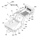
- FIG. 2 is a perspective view illustrating a detailed configuration example of the device pallet 98 and the parent bucket 2.
- the device pallet 98 is formed such that an upright portion 983 is erected at the front end of a substantially rectangular flat portion 981.
- slots 982 extending in the front-rear direction (Y-axis direction) are engraved along the width direction (X-axis direction).
- Positioning holes and connectors are respectively provided at positions corresponding to the slots 982 of the upright portion 983.
- FIG. 2 illustrates a state in which one conventional feeder 8 is mounted. Actually, a maximum of 20 feeders 8 are arranged in the device pallet 98. The positioning pin provided on the front surface of the feeder 8 is fitted into the positioning hole of the upright portion 983. Thereby, the attachment position of the feeder 8 with respect to the device pallet 98 is determined. At the same time, the connector provided on the front surface of the feeder 8 is fitted to the connector of the upright portion 983. As a result, the feeder 8 is connected to the control device 96 in communication and supplied with power. The tape discharge duct 985 disposed on the machine base 91 discharges the used carrier tape 72 coming out of the feeder 8 downward.
- the feeder 8 has a tape insertion port 81 near the rear intermediate height.
- a feed-out rail 82 is disposed from the tape insertion port 81 of the feeder 8 toward the upper part of the front end.
- a component supply position 83 is set on the upper surface near the front end of the feed rail 82.
- a sprocket 84 is rotatably supported on the lower side behind the supply position 83 of the feed rail 82. The teeth of the sprocket 84 protrude from the groove formed in the feed rail 82 and fit into the sprocket hole of the carrier tape.
- the sprocket 84 is intermittently rotated by a motor (not shown), pulls out the carrier tape 72 from the tape reel 71 and feeds it to the component supply position 83 by a predetermined pitch.
- a tape peeling mechanism (not shown) is provided at a position near the sprocket 84 on the upper surface of the feed rail 82.
- the feeder lined up on the device pallet 98 is not limited to the conventional feeder 8 described above.
- a splicing-less feeder (auto loading feeder) disclosed in Patent Document 1 that does not require the splicing operation of the carrier tape 72, or a multi-feeder that supplies two types of parts by alternately moving the two carrier tapes 72 back and forth.
- a splicing-less feeder auto loading feeder
- a multi-feeder that supplies two types of parts by alternately moving the two carrier tapes 72 back and forth.
- new type splicing-less feeder and multi-feeder hereinafter abbreviated as “new type feeder” are used with two carrier tapes 72 inserted, two tape reels 71 are required per unit.
- the parent bucket 2 can hold the tape reel 71 corresponding to the conventional feeders 8 arranged in the width direction of the electronic component mounting machine 9. That is, it is possible to configure the component supply device 93 using the parent bucket 2 to supply one tape reel 71 for each feeder 8 and not using the child bucket 3 described later.
- the parent bucket 2 may be an existing bucket member provided in an existing electronic component mounting machine 9 or may be a part of a newly manufactured electronic component mounting machine 9.
- the parent bucket 2 includes two arm members 21, two side plates 22, four parent roller shafts 231 to 234, a plurality of parent support rollers 241 to 244, two parent partition plate holding shafts 251 and 252, and It is composed of a plurality of parent partition plates 26 and the like.
- the two arm members 21 are fixed to rear portions on both sides in the width direction of the flat portion 981 of the device pallet 98.
- the arm member 21 is formed so as to extend in the horizontal rear at first, then incline toward the rear downward direction, and finally extend in the horizontal rear.
- a handle 28 is provided by connecting the rear portions of the two arm members 21. By pulling the handle 28, the entire component supply device 93 can be removed rearward from the electronic component mounting machine 9.
- Side plates 22 are disposed on the upper side of the inclined portion and the rear horizontal portion of the two arm members 21, respectively.
- the two side plates 22 are arranged in parallel at a separation distance wider than the width dimension of the device pallet 98.
- the side plate 22 is formed with a large front side and a small rear side. Between the two side plates 22, four parent roller shafts 231 to 234 and two parent partition plate holding shafts 251 and 252 are bridged.
- the lower three main roller shafts 231 to 233 are arranged near the front, near the center, and near the rear of the lower portion of the side plate 22.
- the upper single parent roller shaft 234 is disposed near the front side of the upper portion of the side plate 22.
- Each of the parent roller shafts 231 to 234 rotatably supports a plurality of parent support rollers 241 to 244 (shown in FIG. 5) on the outer periphery.
- the width of each of the parent support rollers 241 to 244 is slightly larger than the width of the tape reel 71.
- a parent support shaft having a smooth outer peripheral surface can be used.
- the tape reel 71 is placed between the parent roller shaft 231 on the front side and the parent roller shaft 232 near the center, or between the parent roller shaft 232 near the center and the parent roller shaft 233 on the rear side. Retained. Accordingly, the two sets of front and rear parent support rollers 241 and 242 or the two front and rear sets of parent support rollers 242 and 243 are paired to rotatably support the lower outer periphery of the tape reel 71. Further, the parent support roller 244 of the upper parent roller shaft 234 guides the carrier tape 72 fed from the tape reel 71 to the tape insertion port 81 of the feeder 8.
- the parent partition plate holding shafts 251 and 252 are arranged near the upper part of the front side of the side plate 22 and in the vicinity of the rear end of the side plate 22.
- the two front and rear parent partition plate holding shafts 251 and 252 hold the plurality of parent partition plates 26 in a detachable manner.
- the parent partition plate 26 can be inserted between the tape reels 71 and is held substantially parallel to the side plate 22. In the configuration example of FIG. 2, the main partition plate 26 is inserted every two tape reels 71.
- the reel holding device 1 according to the embodiment includes a parent bucket 2, a child bucket 3, a front reel holder portion 4 and a rear reel holder portion 5 formed in the child bucket 3.
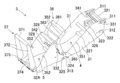
- FIG. 3 is a perspective view of the child bucket 3.
- FIG. 4 is a perspective view showing a state where the child bucket 3 holds the tape reel 71.
- the child bucket 3 includes two side plates 31, five connection shafts 321 to 325, five roller shafts 326 to 329 and 32 A, and two child partition plate holding shafts 331 and 332. , And two sets of anti-floating mechanisms 36, 37, and the like.
- the side plate 31 is a plate material that is long in the front-rear direction and narrowed at the middle part in the front-rear direction.
- the two side plates 31 are spaced apart from each other and arranged in parallel.
- An upper mounting groove 311 extending in the front-rear direction is formed in the upper front end of the two side plates 31.
- a lower mounting groove 312 extending in the front-rear direction is formed at the lower front end of the two side plates 31.
- a bowl-shaped bottom mounting groove 313 is formed below the middle part of the two side plates 31.
- the upper mounting groove 311 and the bottom mounting groove 313 are used when the child bucket 3 is mounted on the parent bucket 2.
- the lower mounting groove 312 is used in combination with the upper mounting groove 311 in another application, for example, when the child bucket 3 is kept in a storage place.
- the front reel holder portion 4 is provided near the front side of the internal space between the two side plates 31, and the rear reel holder portion 5 is provided near the rear side of the internal space.
- the separation distance between the two side plates 31 is set according to the number of tape reels 71 held. In this embodiment, as shown in FIG. 4, ten tape reels 71 are respectively held in the width direction in the front reel holder portion 4 and the rear reel holder portion 5.
- the first connecting shaft 321 is disposed on the lower side near the groove opening of the upper mounting groove 311.
- the second connecting shaft 322 is disposed on the lower side near the groove opening of the lower mounting groove 312.
- the third connecting shaft 323 is disposed near the bottom of the lower mounting groove 312.
- the fourth connecting shaft 324 and the fifth connecting shaft 325 are respectively disposed before and after the bottom mounting groove 313.
- roller shafts 326 to 329 and 32A are bridged between the two side plates 31.
- the first roller shaft 326 and the second roller shaft 327 are arranged side by side on the front side of the front reel holder portion 4.
- the third roller shaft 328 and the fourth roller shaft 329 are arranged side by side vertically on the front side of the rear reel holder portion 5.
- the fifth roller shaft 32 ⁇ / b> A is disposed on the lower side of the rear side of the rear reel holder portion 5.
- the first to fifth roller shafts 326 to 329 and 32A are rotatably supported by rollers which are long in the width direction on their outer circumferences. [0]
- the first child partition plate holding shaft 331 is disposed in the vicinity of the groove bottom of the upper mounting groove 311.
- the second child partition plate holding shaft 332 is disposed slightly above and in front of the tenth connecting shaft 32A.
- Grooves 341 for inserting a front child partition plate 61 are cut at nine locations in the width direction of the first child partition plate holding shaft 331.
- grooves 342 into which the rear child partition plate 65 described later is inserted are cut at nine positions in the width direction of the second child partition plate holding shaft 332.
- the distance between adjacent grooves 341 and 342 is approximately the same as the width of the tape reel 71.
- the two side plates 31 are coupled in parallel by connecting shafts 321 to 325, roller shafts 326 to 329, and 32A, and child partition plate holding shafts 331 and 332, respectively. Thereby, the mechanical strength of the child bucket 3 is ensured.
- the first bearing convex portion 351 is disposed at the center of the front reel holder portion 4.
- the second bearing convex portion 352 is disposed at the center of the rear reel holder portion 5.
- Each of the bearing protrusions 351 and 352 supports the axis of the tape reel 71 at both ends in the width direction.
- the first levitation preventing mechanism 36 is erected on the upper side of the bottom mounting groove 313.
- the first levitation prevention mechanism 36 includes a levitation prevention roller shaft 361 and a pair of turning members 362.
- the floating prevention roller shaft 361 extends in the width direction at a position above the front reel holder portion 4.
- the anti-floating roller shaft 361 is supported by a roller that is long in the width direction so as to be rotatable on the outer periphery.
- the anti-floating roller shaft 361 prevents the tape reel 71 that is pulled upward by the tension acting on the carrier tape 72 from floating.
- the turning member 362 is a rod-shaped member that is curved toward the front reel holder portion 4.
- the pair of turning members 362 are connected by two connecting rods 363.
- the pair of turning members 362 support the end portion of the anti-floating roller shaft 361 at one upper end thereof.
- the pair of turning members 362 has the other lower end fixed to the support member 364.
- FIG. 5 is a partially enlarged perspective view for explaining the support structure of the first levitation preventing mechanism 36.
- the support member 364 is disposed between the two side plates 31.
- a rectangular rod-like support member 365 is bridged between the two side plates 31. At nine locations in the width direction of the support member 365, grooves into which a front side divider partition plate 61 described later is inserted are cut. The distance between adjacent grooves is approximately the same as the width of the tape reel 71.
- the support member 365 has a turning restriction portion 366 on the outer side on both sides in the width direction, and has a turning support portion 367 on the inner side.
- the turning support portion 367 supports the support member 364 in a rotatable manner.
- the turning restricting portion 366 restricts the rotation of the support member 364 to the rear.
- the first levitation prevention mechanism 36 can be manually turned.
- the pivot member 362 pivots in the rearward direction with one end away from the feeder 8 around the support member 364 on the other end side.
- the support member 364 is in contact with the turning restricting portion 366, and the anti-floating roller shaft 361 has moved to the retracted position.
- FIG. 3 shows the retracted position of the anti-floating roller shaft 361 of the first anti-floating mechanism 36
- FIG. 4 shows the upper position of the anti-floating roller shaft 361.
- the tape reel 71 can be exchanged in the front reel holder portion 4.
- the tape reel 71 is inserted between the two side plates 31 by the operator.
- the first levitation prevention mechanism 36 is turned forward by the operator, and the levitation prevention roller shaft 361 moves to the upper position.
- the curved revolving member 362 does not contact the tape reel 71. Therefore, the risk of a problem that the turning member 362 enters between the reel flanges of the tape reels 71 at both ends is avoided in advance.
- the second anti-floating mechanism 37 is erected on the rear side of the fifth roller shaft 32A.
- the second levitation prevention mechanism 37 includes a levitation prevention roller shaft 371 and a pair of turning members 372.
- the floating prevention roller shaft 371 extends in the width direction at a position above the rear reel holder portion 5.
- the anti-floating roller shaft 371 is supported by a roller that is long in the width direction so as to be rotatable on the outer periphery.
- the anti-floating roller shaft 371 prevents the tape reel 71 from being lifted upward by the tension acting on the carrier tape 72.
- the swivel member 372 is a rod-shaped member that extends linearly.
- the pair of turning members 372 support the end portion of the anti-lift roller shaft 371 at one upper end thereof.
- the pair of turning members 372 has the other lower end fixed to the support member 374.
- FIG. 6 is a partially enlarged perspective view for explaining the support structure of the second levitation prevention mechanism 37.
- the support member 374 is disposed between the two side plates 31.
- a rectangular rod-shaped support member 375 is bridged between the two side plates 31. At nine locations in the width direction of the support member 375, grooves into which a rear child partition plate 65 described later is inserted are cut. The distance between adjacent grooves is approximately the same as the width of the tape reel 71.
- the support member 375 has a turning restriction portion 376 on the outer side on both sides in the width direction, and has a turning support portion 377 on the inner side.
- the turning support portion 377 supports the support member 374 in a rotatable manner.
- the turning restricting portion 376 restricts the backward rotation of the support member 374.
- the second levitation prevention mechanism 37 can be manually turned.
- the pivot member 372 pivots in the backward direction with one end away from the feeder 8 around the support member 374 on the other end side.
- the support member 374 is in contact with the turning restricting portion 376, and the anti-floating roller shaft 371 is moved to the retracted position.
- FIG. 3 shows a retracted position of the anti-floating roller shaft 371 of the second anti-floating mechanism 37
- FIG. 4 shows an upper position of the anti-floating roller shaft 371.
- the tape reel 71 can be exchanged in the rear reel holder portion 5.
- the tape reel 71 is inserted between the two turning members 372 by the operator.
- the second levitation prevention mechanism 37 is turned forward by the operator, and the levitation prevention roller shaft 371 moves to the upper position.
- the linear swivel member 372 moves outside the tape reels 71 at both ends.
- the replacement work of the tape reel 71 can be performed in either the single state of the child bucket 3 or the state where the child bucket 3 is attached to the parent bucket 2. Furthermore, it is possible to use a simple shaft member in place of the two anti-floating roller shafts 361 and 371. Further, the shapes of the two types of swiveling members 362 and 372 can be changed, and both swiveling members 362 and 372 may have a curved shape, or both swiveling members 362 and 372 may have a linear shape. Good.
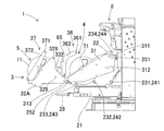
- FIG. 7 is a side view of the reel holding device 1 according to the embodiment in which the child bucket 3 is attached to the parent bucket 2. In FIG. 7, the side plate 22 on the near side of the parent bucket 2 is omitted.
- the operator first advances the child bucket 3 from the rear toward the parent bucket 2.
- the parent partition plate holding shaft 251 on the front side of the parent bucket 2 starts to engage with the upper mounting groove 311 of the child bucket 3.
- the operator presses the child bucket 3 downward while further moving it forward.
- the parent partition plate holding shaft 252 on the rear side of the parent bucket 2 is inserted to the back of the saddle-shaped bottom portion mounting groove 313 of the child bucket 3 and the mounting ends.
- the operator repeats the mounting operation described above for the two child buckets 3.
- the operator decides to arrange the new feeders in one place and removes the four main partition plates 26 corresponding to the arrangement positions. Thereafter, the operator may perform the mounting operation described above once.
- the parent bucket 2 can hold one tape reel 71 corresponding to the conventional feeder 8 in a range where the parent partition plate 26 is not removed. That is, the parent bucket 2 can hold one child bucket 3 and ten or less tape reels 71 side by side in the width direction.
- the plurality of tape reels 71 held by the front reel holder portion 4 are rotatably supported at the lower outer periphery by the parent support rollers 242 and 243 originally provided in the parent bucket 2.
- the plurality of tape reels 71 held by the rear reel holder unit 5 are rotatably supported by the fourth roller shaft 329 and the fifth roller shaft 32A at the lower outer periphery.
- the fourth roller shaft 329 and the fifth roller connecting shaft 32A it is possible to use a support shaft having a smooth outer peripheral surface.
- the front reel holder portion 4 and the rear reel holder portion 5 are equipped with less than ten tape reels 71 and the empty tape reel 71 is not used. In this case, a play dimension is generated in the width direction, and there is a concern that the tape reel 71 may move or tilt in the width direction. Therefore, it is preferable to use the child partition plates 61 and 65.
- FIG. 8 is a perspective view of the front child partition plate 61 used for the front reel holder portion 4
- FIG. 9 is a perspective view of the rear child partition plate 65 used for the rear reel holder portion 5.
- the front child divider plate 61 is formed of a thin plate material having a narrow width.
- the shape of the upper edge of the front child partition plate 61 is the same as that of the upper edge of the side plate 31.
- a mounting groove 62 extending in the front-rear direction is formed on the front side of the front child partition plate 61.
- An attachment notch 63 is formed in the lower rear portion of the front child partition plate 61.
- the attachment groove 62 is inserted into the groove 341 of the first child partition plate holding shaft 331, and movement in the forward direction, the width direction, and the vertical direction is restricted.
- the attachment notch 63 is inserted into the groove of the support member 365, and the rearward and downward movement is restricted (see FIG. 5).
- the front child partition plate 61 is detachable at a desired inter-reel position between the plurality of tape reels 71 arranged in the width direction.
- the rear child partition plate 65 is also formed of a thin plate material having a narrow width.
- a mounting groove 66 that opens downward is formed below the front edge of the lower edge of the rear child partition plate 65.
- An attachment notch 67 is formed in the lower rear portion of the rear child partition plate 65.
- the attachment groove 66 is inserted into the groove 342 of the second child partition plate holding shaft 332, and movement in the front-rear direction, the width direction, and the downward direction is restricted.
- the attachment notch 67 is inserted into the groove of the support member 375, and the rearward and downward movement is restricted (see FIG. 6).
- the rear child partition plate 65 is detachable at a desired inter-reel position between the plurality of tape reels 71 arranged in the width direction.
- the front child partition plate 61 and the rear child partition plate 65 are detachable at a desired inter-reel position between the plurality of tape reels 71 arranged in the width direction.
- the front child divider plate 61 and the rear child divider plate 65 are used, for example, every third or fourth tape reel 71. According to this, even when the front reel holder portion 4 and the rear reel holder portion 5 are equipped with less than ten tape reels 71, problems due to movement or inclination of the tape reel 71 in the width direction can be prevented in advance.
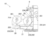
- FIG. 10 is a side view of the component holding device 1X of the first reference embodiment.
- the parent partition plate 26 used for the parent bucket 2 is replaced with a large parent partition plate 26X extended rearward. Near the rear portion of the large parent partition plate 26X, a center pin 261 that supports the axis of the second tape reel 71X is erected in the width direction.
- a large master partition plate 26X is required for each new feeder, and the tape reel 71X must be attached to and detached from the center pin 261 in the width direction. Therefore, the arrangement pitch in the width direction of the tape reels 71 and 71X cannot be reduced, and the number of tape reels 71 and 71X that can be held is limited. For example, when 20 new feeders are arranged in the device pallet 98, 40 tape reels 71 and 71X cannot be held. Furthermore, the number of large parent partition plates 26X becomes too large and handling is complicated.
- FIG. 11 is a side view of the child bucket 3Y constituting the component holding device of the second reference form.
- the front child partition plate 61 and the rear child partition plate 65 are inserted between all the reels of the tape reel 71 arranged in the front reel holder portion 4Y and the rear reel holder portion 5Y.
- the width direction dimension W of the child bucket 3Y is larger than that of the child bucket 3 of the embodiment. Accordingly, it becomes difficult to mount the two child buckets 3Y side by side in the width direction of the parent bucket 2.
- the arrangement pitch in the width direction of the tape reel 71 can be reduced.
- two child buckets 3 can be mounted side by side in the width direction of the parent bucket 2. Therefore, even when 20 new feeders are fully equipped in the device pallet 98, 40 tape reels 71 (twice the number of new feeders) can be held by the two child buckets 3.
- the reel holding device 1 is used in an electronic component mounting machine 9 in combination with a feeder 8 that feeds out carrier tapes 72 each storing components in a plurality of component storage units and can collect components at a supply position.
- a reel holding device 1 that holds a tape reel 71 around which a tape 72 is wound in a rotatable and replaceable manner, and corresponds to the plurality of feeders 8 arranged in the width direction of the electronic component mounting machine 9.
- a parent bucket 2 that can hold 71, a child bucket 3 that is detachably held with respect to the parent bucket 2, and a side closer to the feeder 8 of the child bucket 3, and a plurality of tape reels 71 are arranged in the width direction.
- the reel holding device 1 of the embodiment can hold a large number of tape reels 71 with a limited width dimension. As a result, even when a plurality of new feeders are arranged in the device pallet 98, the slave bucket 3 can hold the tape reels 71 twice as many as the number of new feeders.
- the reel holding device 1 of the embodiment can divert the existing bucket member to the parent bucket 2, it can be easily applied to the existing electronic component mounting machine 9.
- the reel holding device 1 according to the embodiment is resource-saving and low-cost because the number of members to be added is small when applied to existing equipment.
- At least one of the front reel holder portion 4 and the rear reel holder portion 5 extends in the width direction at a position above the plurality of held tape reels 71 to prevent the tape reel 71 from floating.
- 371, and swivel members 362, 372 that support the anti-lift roller shafts 361, 371 at one end and are rotatably supported on the child bucket 3 at the other end.
- the parent bucket 2 can hold the child bucket 3 and the tape reel 71 side by side in the width direction, and extends in the width direction and rotatably supports the lower outer periphery of the tape reel 71.
- the plurality of tape reels 71 having 242 and 243 or a parent support shaft and held by the front reel holder portion 4 are rotatably supported at the lower outer periphery by the parent support rollers 241 242 243 or the parent support shaft. .
- the tape reel 71 directly held in the parent bucket 2 and the two front and rear tape reels 71 held in the child bucket 3 attached to the parent bucket 2 can be used together. Therefore, when a plurality of types of feeders are used in combination, for example, when the conventional feeder 8 and the new feeder are used together, it can be flexibly handled. Further, the tape reel 71 of the front reel holder portion 4 of the child bucket 3 can be supported using the parent support rollers 241, 242, and 243 originally provided in the parent bucket 2. Therefore, the child roller 3 has a reduced number of constituent members, is lightweight, and is low in cost.
- the parent bucket 3 includes a parent partition plate 26 that can be inserted into a desired inter-reel position between the plurality of tape reels 71, and a parent partition plate that extends in the width direction and detachably holds the parent partition plate 26.
- the child bucket 3 is attached to the main partition plate holding shafts 251 and 252. According to this, the child bucket 3 can be mounted using the parent partition plate holding shafts 251 and 252 originally provided in the parent bucket 2. Therefore, when applied to the existing electronic component mounting machine 9, the existing bucket member can be diverted to the parent bucket 2 without major modification.
- the front reel holder portion 4 and the rear reel holder portion 5 are provided with a front child partition plate 61 and a rear child partition plate 65 that are detachable at a desired inter-reel position between the plurality of tape reels 71 arranged in the width direction.
- a front child partition plate 61 and a rear child partition plate 65 that are detachable at a desired inter-reel position between the plurality of tape reels 71 arranged in the width direction.
- Reel holding device 2 Parent bucket 21: Arm member 22: Side plate 231 to 234: Parent roller shaft 241 to 244: Parent support roller 251 and 252: Parent partition plate holding shaft 26: Parent partition plate 3: Child bucket 31: Side plates 321 to 329, 32A, 32B: connecting shafts 331, 332: child partition plate holding shafts 36: anti-floating mechanism 361: anti-floating roller shaft 362: swivel member 37: anti-floating mechanism 371: anti-floating roller shaft 372: swivel member 4: Front reel holder portion 5: Rear reel holder portion 61: Front child partition plate 65: Rear child partition plate 71, 71X: Tape reel 72: Carrier tape 8: Feeder 9: Electronic component mounting machine 93: Component supply device 98: Device palette 1X: Part holding device of the first reference form 26X: Large parent partition plate Y: child bucket of the second reference form
Landscapes
- Engineering & Computer Science (AREA)
- Manufacturing & Machinery (AREA)
- Microelectronics & Electronic Packaging (AREA)
- Supply And Installment Of Electrical Components (AREA)
- Replacement Of Web Rolls (AREA)
Abstract
本発明は、キャリアテープ(72)が巻回されたテープリール(71)を回転可能かつ交換可能に保持するリール保持装置(1)であって、複数のフィーダ(8)に対応してテープリールを保持可能な親バケット(2)と、親バケットに対して着脱可能に保持される子バケット(3)と、子バケットのフィーダに近い側に形成されて複数のテープリールを幅方向に並べて保持する前側リールホルダ部(4)と、子バケットのフィーダから離れた側に形成されて複数のテープリールを幅方向に並べて保持する後側リールホルダ部と(5)を備えた。これによれば、前側リールホルダ部および後側リールホルダ部の幅方向に並んだテープリールの相互間には、側板や仕切り板などの部材が不要であるので、リール保持装置は、限られた幅寸法で多数のテープリールを保持できる。
Description
本発明は、電子部品装着機に装備されるフィーダと組み合わせて使用され、キャリアテープが巻回されたテープリールを回転可能に保持するリール保持装置に関する。
多数の部品が装着された基板を生産する設備として、はんだ印刷機、電子部品装着機、リフロー機、基板検査機などがある。これらの設備を連結して基板生産ラインを構成することが一般的になっている。このうち電子部品装着機は、基板搬送装置、部品供給装置、部品移載装置、および制御装置を備える。部品供給装置の代表例として、複数の部品収納部にそれぞれ部品を収納したキャリアテープを繰り出す方式のフィーダがある。このフィーダと組み合わせて、キャリアテープが巻回されたテープリールを回転可能かつ交換可能に保持するリール保持装置が使用される。この種のリール保持装置に関する一技術例が、特許文献1に開示されている。
特許文献1は、電子部品装着機の部品供給部に装着されるリール保持具を開示している。このリール保持具は、キャリアテープを巻回収納したリールを保持する第1および第2のリールホルダ部を有し、2つのリールホルダ部がテープ送り方向に直列配置されている。これによれば、複数のリールを保持でき、特にスプライシングレスフィーダ(オートローディングフィーダ)において先行リールと後続リールとを作業性良く保持できる、とされている。
ところで、特許文献1の技術例では、スプライシング作業を省略するために、1台のフィーダ(オートローディングフィーダ)に2つのテープリールを使用する。このような新型のフィーダを幅方向に列設する場合に、従来よりも多数のテープリールを保持する必要が生じる。しかしながら、特許文献1の技術例では、前後2つのリールホルダ部を形成するために2枚の側板部を用いており、部品保持具の幅方向寸法が大きい。このため、列設されるフィーダの配設ピッチよりも、部品保持具の配設ピッチのほうが大きくなってしまうケースが生じる。その結果、列設される新型のフィーダに対して、部品保持具に保持されるテープリールの個数が不足する。
また、フィーダは、その種類や構造に関係なく列設されるように互換性を有している場合が多い。ところが、特許文献1の技術例では、複数種類のフィーダを併用する場合が考慮されていない。
本発明は、上記背景技術の問題点に鑑みてなされたものであり、前後2箇所に保持するテープリールの幅方向の配設ピッチを小さくして、限られた幅寸法で多数のテープリールを保持できるようにしたリール保持装置を提供することを解決すべき課題とする。
上記課題を解決する本発明のリール保持装置は、複数の部品収納部にそれぞれ部品を収納したキャリアテープを繰り出して供給位置で前記部品を採取可能とするフィーダと組み合わせて電子部品装着機に用いられ、前記キャリアテープが巻回されたテープリールを回転可能かつ交換可能に保持するリール保持装置であって、前記電子部品装着機の幅方向に列設される複数の前記フィーダに対応して前記テープリールを保持可能な親バケットと、前記親バケットに対して着脱可能に保持される子バケットと、前記子バケットの前記フィーダに近い側に形成され、複数の前記テープリールを前記幅方向に並べて保持する前側リールホルダ部と、前記子バケットの前記フィーダから離れた側に形成され、複数の前記テープリールを前記幅方向に並べて保持する後側リールホルダ部と、を備えた。
本発明のリール保持装置において、子バケットに形成された前側リールホルダ部および後側リールホルダ部は、それぞれ複数のテープリールを幅方向に並べて保持する。そして、幅方向に並んだテープリールの相互間には、側板や仕切り板などの部材が不要であるので、テープリールの幅方向の配設ピッチを小さくできる。したがって、本発明のリール保持装置は、限られた幅寸法で多数のテープリールを保持できる。
(1.電子部品装着機9の全体構成)
本発明の実施形態のリール保持装置1について、図1~図9を参考にして説明する。まず、リール保持装置1を用いる電子部品装着機9の全体構成について説明する。図1は、実施形態のリール保持装置1を用いる電子部品装着機9の全体構成を模式的に示す平面図である。図1の紙面左側から右側に向かう方向が基板Kを搬入出するX軸方向、紙面下側の後方から紙面上側の前方に向かう方向がY軸方向である。電子部品装着機9は、基板搬送装置92、部品供給装置93、部品移載装置94、部品カメラ95、および制御装置96などが機台91に組み付けられて構成されている。基板搬送装置92、部品供給装置93、部品移載装置94、および部品カメラ95は、制御装置96から制御され、それぞれが所定の作業を行うようになっている。
本発明の実施形態のリール保持装置1について、図1~図9を参考にして説明する。まず、リール保持装置1を用いる電子部品装着機9の全体構成について説明する。図1は、実施形態のリール保持装置1を用いる電子部品装着機9の全体構成を模式的に示す平面図である。図1の紙面左側から右側に向かう方向が基板Kを搬入出するX軸方向、紙面下側の後方から紙面上側の前方に向かう方向がY軸方向である。電子部品装着機9は、基板搬送装置92、部品供給装置93、部品移載装置94、部品カメラ95、および制御装置96などが機台91に組み付けられて構成されている。基板搬送装置92、部品供給装置93、部品移載装置94、および部品カメラ95は、制御装置96から制御され、それぞれが所定の作業を行うようになっている。
基板搬送装置92は、基板搬送部925およびバックアップ部926などで構成されている。基板搬送部925は、一対のガイドレール921、922や一対のコンベアベルトなどからなり、基板Kを装着実施位置に搬入出する。バックアップ部926は、装着実施位置の下側に配設されており、基板Kを押し上げて位置決めする。
部品供給装置93は、デバイスパレット98およびバケット部材を基にして構成されている。デバイスパレット98は、略矩形状の部材であり、上面に複数台のフィーダ8が列設される。デバイスパレット98は、機台91の後方に着脱可能に装備される。デバイスパレット98の後側に、バケット部材が配設されている。バケット部材は、本発明の親バケット2に相当する部材である。デバイスパレット98および親バケット2の詳細な構成については後述する。
部品移載装置94は、複数のフィーダ8から部品を吸着採取し、位置決めされた基板Kまで搬送して装着する。部品移載装置94は、X軸方向およびY軸方向に水平移動可能なXYロボットタイプの装置である。部品移載装置94は、ヘッド駆動機構を構成する一対のY軸レール941、942およびY軸スライダ943、X軸方向およびY軸方向に駆動される装着ヘッド944、ノズルツール945、吸着ノズル946、ならびに基板カメラ947などで構成されている。ノズルツール945は、装着ヘッド944に交換可能に保持される一方で、下側に吸着ノズル946を保持している。吸着ノズル946は、部品を吸着して、基板Kに装着する。基板カメラ947は、装着ヘッド944に設けられており、基板Kに付設された位置基準マークを撮像して、基板Kの正確な位置を検出する。
部品カメラ95は、基板搬送装置92と部品供給装置93との間の機台91の上面に、上向きに設けられている。部品カメラ95は、装着ヘッド944がフィーダ8から基板K上に移動する途中で、吸着ノズル946に吸着されている部品の状態を撮像する。制御装置96は、機台91に組み付けられており、その配設位置は特に限定されない。制御装置96は、予め保持した装着シーケンスにしたがって部品装着動作を制御する。
次に、デバイスパレット98および親バケット2の詳細な構成について説明する。図2は、デバイスパレット98および親バケット2の詳細な構成例を示す斜視図である。デバイスパレット98は、略矩形の平面部981の前端に直立部983が立設されて形成されている。平面部981には、前後方向(Y軸方向)に延びるスロット982が幅方向(X軸方向)に並んで刻設されている。直立部983の各スロット982に対応する位置に、それぞれ位置決め孔およびコネクタが設けられている。
フィーダ8は、それぞれデバイスパレット98のスロット982の後側から前方へと挿入され、幅方向(X軸方向)に並んで装着される。図2は、従来型のフィーダ8の1台が装着された状態を例示している。実際には、最大で20台のフィーダ8がデバイスパレット98に列設される。フィーダ8の前面に設けられた位置決めピンは、直立部983の位置決め孔に嵌入する。これにより、フィーダ8は、デバイスパレット98に対する装着位置が決められる。同時に、フィーダ8の前面に設けられたコネクタは、直立部983のコネクタに嵌合する。これにより、フィーダ8は、制御装置96に通信接続されるとともに、電源が供給される。機台91側に配設されたテープ排出ダクト985は、フィーダ8から出てくる使用済みのキャリアテープ72を下方へと排出する。
フィーダ8は、後部の中間高さ付近にテープ挿入口81を有している。フィーダ8のテープ挿入口81から前端上部に向けて繰り出しレール82が配設されている。繰り出しレール82の前端付近の上面に、部品供給位置83が設定されている。繰り出しレール82の供給位置83よりも後ろの下側に、スプロケット84が回転可能に支承されている。スプロケット84の歯は、繰り出しレール82に形成された溝から突出して、キャリアテープのスプロケット孔に嵌入する。スプロケット84は、図略のモータにより間欠的に回転駆動され、テープリール71からキャリアテープ72を引き出して、所定ピッチずつ部品供給位置83へ繰り出す。繰り出しレール82の上面のスプロケット84に近い位置に、図略のテープ剥離機構が設けられている。
デバイスパレット98上に列設されるフィーダは、上述した従来型のフィーダ8に限定されない。例えば、キャリアテープ72のスプライシング作業を不要とする特許文献1に開示されたスプライシングレスフィーダ(オートローディングフィーダ)や、2本のキャリアテープ72を交互に進退させて2種類の部品を供給するマルチフィーダ(例えば、特許第4856761号参照)も列設可能である。新型のスプライシングレスフィーダやマルチフィーダ(以降は新型フィーダと略記する)は、2本のキャリアテープ72を挿入して使用するため、1台あたり2個のテープリール71が必要になる。
親バケット2は、電子部品装着機9の幅方向に列設される従来型のフィーダ8に対応してテープリール71を保持できる。つまり、フィーダ8の1台につき1個のテープリール71を供給するために親バケット2を用い、後述する子バケット3を使用せずに部品供給装置93を構成することができる。親バケット2は、既設の電子部品装着機9に設けられた既存のバケット部材であってもよく、新規に製造される電子部品装着機9の一部であってもよい。親バケット2は、2本のアーム部材21、2枚の側板22、4本の親ローラ軸231~234、複数の親支持ローラ241~244、2本の親仕切り板保持軸251、252、および複数の親仕切り板26などで構成されている。
2本のアーム部材21は、デバイスパレット98の平面部981の幅方向の両側の後部に固定されている。アーム部材21は、初めは水平後方に延び、続いて後下方向へと傾斜して延び、最後は水平後方に延びるように形成されている。2本のアーム部材21の後部を連結して把手28が設けられている。把手28を引くことにより、部品供給装置93の全体を電子部品装着機9から後方へ取り外せる。
2本のアーム部材21の傾斜部分および後部の水平部分の上側にかけて、それぞれ側板22が配設されている。2枚の側板22は、デバイスパレット98の幅寸法よりも広めの離隔距離で平行配置されている。側板22は、前側の高さが大きく、後側の高さが小さく形成されている。2枚の側板22の間に、4本の親ローラ軸231~234および2本の親仕切り板保持軸251、252が架け渡されている。
下側の3本の親ローラ軸231~233は、側板22の下部の前側寄り、中央付近、および後側寄りに配置されている。上側の1本の親ローラ軸234は、側板22の上部の前側寄りに配置されている。各親ローラ軸231~234は、それぞれ外周に複数の親支持ローラ241~244(図5に示す)を回転可能に軸承している。各親支持ローラ241~244の幅寸法は、テープリール71の幅寸法よりもわずかに大きめとされている。なお、親ローラ軸231~234および親支持ローラ241~244に代えて、外周面を滑らかに仕上げた親支持軸を用いることも可能である。
テープリール71は、前側寄りの親ローラ軸231と中央付近の親ローラ軸232との間、または、中央付近の親ローラ軸232と後側寄りの親ローラ軸233との間に載置されて保持される。これにより、前後2組の親支持ローラ241、242、または前後2組の親支持ローラ242、243は、対になってテープリール71の下側外周を回転可能に支持する。また、上側の親ローラ軸234の親支持ローラ244は、テープリール71から繰り出されたキャリアテープ72をフィーダ8のテープ挿入口81に案内する。
親仕切り板保持軸251、252は、側板22の前側の上部寄り、および側板22の後端付近に配置されている。前後2本の親仕切り板保持軸251、252は、複数の親仕切り板26を着脱可能に保持する。親仕切り板26は、テープリール71の間に挿入可能とされ、側板22に概ね平行に保持される。図2の構成例で、親仕切り板26は、テープリール71の2個ごとに挿入される。
(2.実施形態のリール保持装置1の構成)
デバイスパレット98に新型フィーダが列設されると、親バケット2に保持されるテープリール71の個数が不足する。そこで、本発明の実施形態のリール保持装置1を用いる。実施形態のリール保持装置1は、親バケット2、子バケット3、および子バケット3に形成された前側リールホルダ部4および後側リールホルダ部5などで構成される。図3は、子バケット3の斜視図である。また、図4は、子バケット3がテープリール71を保持した状態の斜視図である。
デバイスパレット98に新型フィーダが列設されると、親バケット2に保持されるテープリール71の個数が不足する。そこで、本発明の実施形態のリール保持装置1を用いる。実施形態のリール保持装置1は、親バケット2、子バケット3、および子バケット3に形成された前側リールホルダ部4および後側リールホルダ部5などで構成される。図3は、子バケット3の斜視図である。また、図4は、子バケット3がテープリール71を保持した状態の斜視図である。
図3に示されるように、子バケット3は、2枚の側板31、5本の連結軸321~325、5本のローラ軸326~329、32A、2本の子仕切り板保持軸331、332、および2組の浮上防止機構36、37などで構成されている。側板31は、前後方向に長く、かつ前後方向の中間部分が細くくびれた板材である。2枚の側板31は、相互に離隔して平行配置される。
2枚の側板31の前端上部に、前後方向に延びる上側装着溝311が形成されている。2枚の側板31の前端下部に、前後方向に延びる下側装着溝312が形成されている。さらに、2枚の側板31の中間部分の下側に鉤型の底部装着溝313が形成されている。上側装着溝311および底部装着溝313は、子バケット3を親バケット2に装着するときに使用される。下側装着溝312は、別の用途、例えば子バケット3を保管場所に留め置く場合などに、上側装着溝311と併せて使用される。
2つの側板31の間の内部空間の前側寄りに前側リールホルダ部4が設けられ、内部空間の後側寄りに後側リールホルダ部5が設けられる。2つの側板31の離隔距離は、保持されるテープリール71の個数に合わせて設定される。本実施形態では、図4に示されるように、前側リールホルダ部4および後側リールホルダ部5に、それぞれ10個のテープリール71が幅方向に並べられて保持される。
2枚の側板31の間に、丸棒形状の5本の連結軸321~325が架け渡されている。第1連結軸321は、上側装着溝311の溝開口付近の下側に配置されている。第2連結軸322は、下側装着溝312の溝開口付近の下側に配置されている。第3連結軸323は、下側装着溝312の溝底付近に配置されている。第4連結軸324および第5連結軸325は、底部装着溝313の前後にそれぞれ配置されている。
さらに、2枚の側板31の間には、5本のローラ軸326~329、32Aが架け渡されている。第1ローラ軸326および第2ローラ軸327は、前側リールホルダ部4の前側に、上下に並んで配置されている。[0]第3ローラ軸328および第4ローラ軸329は、後側リールホルダ部5の前側に、上下に並んで配置されている。第5ローラ軸32Aは、後側リールホルダ部5の後側の下方寄りに配置されている。第1~第5ローラ軸326~329、32Aは、幅方向に長いローラをそれぞれの外周に回転可能に軸承している。[0]
さらに、2枚の側板31の間には、2本の子仕切り板保持軸331、332が架け渡されている。第1子仕切り板保持軸331は、上側装着溝311の溝底付近に配置されている。第2子仕切り板保持軸332は、第10連結軸32Aよりも少し前側上方に配置されている。第1子仕切り板保持軸331の幅方向の9箇所に、後述する前側子仕切り板61を差し込める溝341が切られている。同様に、第2子仕切り板保持軸332の幅方向の9箇所に、後述する後側子仕切り板65を差し込める溝342が切られている。隣り合う溝341、342の離間寸法は、テープリール71の幅寸法と同程度になっている。2枚の側板31は、連結軸321~325、ローラ軸326~329、32A、および子仕切り板保持軸331、332によって平行状態に結合されている。これにより、子バケット3の機械的強度が確保される。
さらに、2枚の側板31の向かい合う内側には、前後2対の軸承凸部351、352が突設されている。第1軸承凸部351は、前側リールホルダ部4の中央に配置されている。第2軸承凸部352は、後側リールホルダ部5の中央に配置されている。各軸承凸部351、352は、幅方向の両端のテープリール71の軸心を軸承する。
第1浮上防止機構36は、底部装着溝313の上側に立設されている。第1浮上防止機構36は、浮上防止ローラ軸361および一対の旋回部材362などからなる。浮上防止ローラ軸361は、前側リールホルダ部4の上方位置で幅方向に延在する。浮上防止ローラ軸361は、幅方向に長いローラを外周に回転可能に軸承している。浮上防止ローラ軸361は、キャリアテープ72に作用する張力によって上方に引っ張られるテープリール71の浮上を防止する。
旋回部材362は、前側リールホルダ部4に向かって湾曲した棒形状の部材である。一対の旋回部材362は、2本の連結棒363によって連結されている。一対の旋回部材362は、それぞれの上側の一端で浮上防止ローラ軸361の端部を支持する。一対の旋回部材362は、それぞれの下側の他端が支承部材364に固定されている。図5は、第1浮上防止機構36の支持構造を説明する部分拡大斜視図である。支承部材364は、2枚の側板31の間に配置されている。
一方、2枚の側板31の間に、矩形棒状の支持部材365が架け渡されている。支持部材365の幅方向の9箇所には、後述する前側子仕切り板61を差し込める溝が切られている。隣り合う溝の離間寸法は、テープリール71の幅寸法と同程度になっている。支持部材365は、幅方向両側の外側寄りに旋回規制部366を有し、内側寄りに旋回支持部367を有する。旋回支持部367は、支承部材364を回転可能に支承している。旋回規制部366は、支承部材364の後方への回転を規制する。第1浮上防止機構36は、手動による旋回操作が可能とされている。旋回部材362は、他端側の支承部材364を中心にして一端がフィーダ8から離れた後ろ方向に旋回する。図5において、支承部材364は旋回規制部366に当接しており、浮上防止ローラ軸361は退避位置に移動している。
図3は、第1浮上防止機構36の浮上防止ローラ軸361の退避位置を示し、図4は、浮上防止ローラ軸361の上方位置を示している。図3の状態で、前側リールホルダ部4におけるテープリール71の交換が可能となっている。テープリール71は、オペレータによって2枚の側板31の間に挿入される。次いで、オペレータにより第1浮上防止機構36が前方向に旋回され、浮上防止ローラ軸361が上方位置に移動する。このとき、湾曲形状の旋回部材362は、テープリール71に当接しない。したがって、旋回部材362が両端のテープリール71のリールフランジ間に入り込んでしまう不具合のおそれは、未然に回避されている。
第2浮上防止機構37は、第5ローラ軸32Aの後側に立設されている。第2浮上防止機構37は、浮上防止ローラ軸371および一対の旋回部材372などからなる。浮上防止ローラ軸371は、後側リールホルダ部5の上方位置で幅方向に延在する。浮上防止ローラ軸371は、幅方向に長いローラを外周に回転可能に軸承している。浮上防止ローラ軸371は、キャリアテープ72に作用する張力によって上方に引っ張られるテープリール71の浮上を防止する。
旋回部材372は、直線的に延びる棒形状の部材である。一対の旋回部材372は、それぞれの上側の一端で浮上防止ローラ軸371の端部を支持する。一対の旋回部材372は、それぞれの下側の他端が支承部材374に固定されている。図6は、第2浮上防止機構37の支持構造を説明する部分拡大斜視図である。支承部材374は、2枚の側板31の間に配置されている。
一方、2枚の側板31の間に、矩形棒状の支持部材375が架け渡されている。支持部材375の幅方向の9箇所には、後述する後側子仕切り板65を差し込める溝が切られている。隣り合う溝の離間寸法は、テープリール71の幅寸法と同程度になっている。支持部材375は、幅方向両側の外側寄りに旋回規制部376を有し、内側寄りに旋回支持部377を有する。旋回支持部377は、支承部材374を回転可能に支承している。旋回規制部376は、支承部材374の後方への回転を規制する。第2浮上防止機構37は、手動による旋回操作が可能とされている。旋回部材372は、他端側の支承部材374を中心にして一端がフィーダ8から離れた後ろ方向に旋回する。図6において、支承部材374は旋回規制部376に当接しており、浮上防止ローラ軸371は退避位置に移動している。
図3は、第2浮上防止機構37の浮上防止ローラ軸371の退避位置を示し、図4は、浮上防止ローラ軸371の上方位置を示している。図3の状態で、後側リールホルダ部5におけるテープリール71の交換が可能となっている。テープリール71は、オペレータによって2個の旋回部材372の間に挿入される。次いで、オペレータにより第2浮上防止機構37が前方向に旋回され、浮上防止ローラ軸371が上方位置に移動する。このとき、直線形状の旋回部材372は、両端のテープリール71の外側を移動する。
なお、テープリール71の交換作業は、子バケット3の単独状態、および、子バケット3が親バケット2に装着された状態のどちらでも実施できる。さらになお、2つの浮上防止ローラ軸361、371に代えて、単純な軸部材を用いることも可能である。また、2種類の旋回部材362、372の形状は変更可能であり、両方の旋回部材362、372が湾曲形状であってもよく、あるいは、両方の旋回部材362、372が直線形状であってもよい。
(3.実施形態のリール保持装置1の使用方法および作用)
次に、実施形態のリール保持装置1の使用方法について説明する。実施形態において、2台または1台の子バケット3を親バケット2に装着できる。デバイスパレット98に新型フィーダが10台を超えて列設される場合には、2台の子バケット3を親バケット2の幅方向の全体にわたって装着する。この場合、オペレータは、親バケット2の親仕切り板保持軸251、252から全部の親仕切り板26を取り外し、代わりに2台の子バケット3を装着する。図7は、子バケット3を親バケット2に装着した実施形態のリール保持装置1の側面図である。図7では、親バケット2の手前側の側板22が省略されている。
次に、実施形態のリール保持装置1の使用方法について説明する。実施形態において、2台または1台の子バケット3を親バケット2に装着できる。デバイスパレット98に新型フィーダが10台を超えて列設される場合には、2台の子バケット3を親バケット2の幅方向の全体にわたって装着する。この場合、オペレータは、親バケット2の親仕切り板保持軸251、252から全部の親仕切り板26を取り外し、代わりに2台の子バケット3を装着する。図7は、子バケット3を親バケット2に装着した実施形態のリール保持装置1の側面図である。図7では、親バケット2の手前側の側板22が省略されている。
子バケット3の装着動作について詳述すると、オペレータは、まず、子バケット3を後方から親バケット2に向けて前進させる。これにより、親バケット2の前側の親仕切り板保持軸251は、子バケット3の上側装着溝311に係入し始める。オペレータは、次に、子バケット3をさらに前進させながら下方に押しつける。これにより、親バケット2の後側の親仕切り板保持軸252は、子バケット3の鉤型の底部装着溝313の奥まで嵌入し、装着が終了する。オペレータは、2台の子バケット3について、上述した装着動作を繰り返す。
また、デバイスパレット98上の新型フィーダが10台以下の場合には、1台の子バケット3で対応可能である。この場合、オペレータは、新型フィーダを1箇所にまとめて列設することに定め、列設位置に対応する4枚の親仕切り板26を取り外す。その後、オペレータは、上述した装着動作を1回行えばよい。親バケット2は、親仕切り板26を取り外さなかった範囲では、従来型のフィーダ8に対応して各1個のテープリール71を保持できる。つまり、親バケット2は、1台の子バケット3と10個以下のテープリール71とを幅方向に並べて保持することができる
図7に示されるように、前側リールホルダ部4に保持された複数のテープリール71は、親バケット2に元から設けられていた親支持ローラ242、243によって下側外周が回転可能に支持される。一方、後側リールホルダ部5に保持された複数のテープリール71は、第4ローラ軸329および第5ローラ軸32Aによって下側外周が回転可能に支持される。なお、第4ローラ軸329および第5ローラ連結軸32Aに代えて、外周面を滑らかに仕上げた支持軸を用いることも可能である。
子バケット3の前側リールホルダ部4や後側リールホルダ部5に10個のテープリール71をフル装備して部品を供給する場合、テープリール71の相互間にわずかな隙間が残される。このため、テープリール71の相互間に大きな摩擦が発生して回転が阻害されることはなく、テープリール71が傾斜することもない。これにより、安定した部品供給動作が確保される。また、10個未満のテープリール71から部品を供給する場合でも、空のテープリール71を入れてフル装備とすることにより、安定した部品供給動作が確保される。
前側リールホルダ部4や後側リールホルダ部5に10個未満のテープリール71を装備し、かつ空のテープリール71を使用しない場合もある。この場合、幅方向に遊び寸法が発生して、テープリール71の幅方向の移動や傾斜などのおそれが生じる。したがって、子仕切り板61、65を用いることが好ましい。図8は、前側リールホルダ部4に用いる前側子仕切り板61の斜視図であり、図9は、後側リールホルダ部5に用いる後側子仕切り板65の斜視図である。
図8に示されるように、前側子仕切り板61は、幅の狭い薄板材で形成されている。前側子仕切り板61の上縁の形状は、側板31の上縁と同じ形状になっている。前側子仕切り板61の前側に、前後方向に延びる取付溝62が形成されている。前側子仕切り板61の後側下部に、取付切欠部63が形成されている。取付溝62は、第1子仕切り板保持軸331の溝341に差し込まれて、前方向、幅方向、および上下方向の移動が規制される。一方、取付切欠部63は、支持部材365の溝に差しこまれて、後方向および下方向の移動が規制される(図5参照)。これにより、前側子仕切り板61は、幅方向に並ぶ複数のテープリール71の間の所望するリール間位置に着脱可能となっている。
図9に示されるように、後側子仕切り板65も、幅の狭い薄板材で形成されている。後側子仕切り板65の下縁の前側寄りの下に、下方に開口する取付溝66が形成されている。後側子仕切り板65の後側下部に、取付切欠部67が形成されている。取付溝66は、第2子仕切り板保持軸332の溝342に差し込まれて、前後方向、幅方向、および下方向の移動が規制される。一方、取付切欠部67は、支持部材375の溝に差しこまれて、後方向および下方向の移動が規制される(図6参照)。これにより、後側子仕切り板65は、幅方向に並ぶ複数のテープリール71の間の所望するリール間位置に着脱可能となっている。
前側子仕切り板61および後側子仕切り板65は、幅方向に並ぶ複数のテープリール71の間の所望するリール間位置に着脱可能とされている。前側子仕切り板61および後側子仕切り板65は、例えば、テープリール71の3個目ごとや4個目ごとに用いる。これによれば、前側リールホルダ部4や後側リールホルダ部5に10個未満のテープリール71を装備した場合でも、テープリール71の幅方向の移動や傾斜などによる不具合を未然に防止できる。
次に、実施形態のリール保持装置1の作用について、第1および第2参考形態と対比して説明する。図10は、第1参考形態の部品保持装置1Xの側面図である。第1参考形態では、親バケット2に用いる親仕切り板26を、後方に延長した大型の親仕切り板26Xに交換して対応している。大型の親仕切り板26Xの後部寄りには、第2のテープリール71Xの軸心を軸承するセンターピン261が幅方向に立設されている。
第1参考形態では、新型フィーダの1台ごとに大型の親仕切り板26Xが必要となり、かつ、センターピン261に対してテープリール71Xを幅方向に着脱しなければならない。したがって、テープリール71、71Xの幅方向の配設ピッチを小さくすることができず、保持できるテープリール71、71Xの個数が限定される。例えば、デバイスパレット98に20台の新型フィーダが列設される場合に、40個のテープリール71、71Xを保持できない。さらには、大型の親仕切り板26Xの枚数が多くなり過ぎて、取り扱いが煩雑である。
また、図11は、第2参考形態の部品保持装置を構成する子バケット3Yの側面図である。第2参考形態では、前側リールホルダ部4Yおよび後側リールホルダ部5Yに並ぶテープリール71の全部のリール相互間に、前側子仕切り板61および後側子仕切り板65が挿入される。第2参考形態では、子バケット3Yの幅方向寸法Wが、実施形態の子バケット3と対比して大きくなる。したがって、2台の子バケット3Yを親バケット2の幅方向に並べて装着することが難しくなる。
第1および第2参考形態と対比して、実施形態のリール保持装置1によれば、テープリール71の幅方向の配設ピッチを小さくすることができる。その結果、2台の子バケット3を親バケット2の幅方向に並べて装着できる。したがって、デバイスパレット98に20台の新型フィーダがフル装備される場合でも、2台の子バケット3によって40個(新型フィーダの台数の2倍)のテープリール71を保持できる。
(4.実施形態のリール保持装置1の態様および効果)
実施形態のリール保持装置1は、複数の部品収納部にそれぞれ部品を収納したキャリアテープ72を繰り出して供給位置で部品を採取可能とするフィーダ8と組み合わせて電子部品装着機9に用いられ、キャリアテープ72が巻回されたテープリール71を回転可能かつ交換可能に保持するリール保持装置1であって、電子部品装着機9の幅方向に列設される複数のフィーダ8に対応してテープリール71を保持可能な親バケット2と、親バケット2に対して着脱可能に保持される子バケット3と、子バケット3のフィーダ8に近い側に形成され、複数のテープリール71を幅方向に並べて保持する前側リールホルダ部4と、子バケット3のフィーダ8から離れた側に形成され、複数のテープリール71を幅方向に並べて保持する後側リールホルダ5部と、を備えた。
実施形態のリール保持装置1は、複数の部品収納部にそれぞれ部品を収納したキャリアテープ72を繰り出して供給位置で部品を採取可能とするフィーダ8と組み合わせて電子部品装着機9に用いられ、キャリアテープ72が巻回されたテープリール71を回転可能かつ交換可能に保持するリール保持装置1であって、電子部品装着機9の幅方向に列設される複数のフィーダ8に対応してテープリール71を保持可能な親バケット2と、親バケット2に対して着脱可能に保持される子バケット3と、子バケット3のフィーダ8に近い側に形成され、複数のテープリール71を幅方向に並べて保持する前側リールホルダ部4と、子バケット3のフィーダ8から離れた側に形成され、複数のテープリール71を幅方向に並べて保持する後側リールホルダ5部と、を備えた。
これによれば、前側リールホルダ部4および後側リールホルダ部5の幅方向に並んだテープリール71の相互間には、側板や仕切り板などの部材が不要であるので、テープリール71の幅方向の配設ピッチを小さくできる。したがって、実施形態のリール保持装置1は、限られた幅寸法で多数のテープリール71を保持できる。これにより、デバイスパレット98に複数の新型フィーダが列設される場合でも、子バケット3によって新型フィーダの台数の2倍のテープリール71を保持できる。
また、実施形態のリール保持装置1は、既存のバケット部材を親バケット2に転用することができるので、既設の電子部品装着機9への適用が容易である。加えて、実施形態のリール保持装置1は、既設への適用時に追加する部材点数が少なくて済むので、省資源であるとともに低コストである。
さらに、前側リールホルダ部4および後側リールホルダ部5の少なくとも一方は、保持した複数のテープリール71の上方位置で幅方向に延在してテープリール71の浮上を防止する浮上防止ローラ軸361、371と、一端で浮上防止ローラ軸361、371を支持するとともに、他端が子バケット3に回転可能に支承された旋回部材362、372と、を有し、旋回部材362、372は、他端を中心にして一端がフィーダ8から離れた方向に旋回することにより、浮上防止ローラ軸361、371を上方位置から退避位置に移動させて、テープリール71の交換を可能にする。
これによれば、テープリール71の浮上が防止されるので、部品供給動作の信頼性が高い。加えて、簡単な旋回操作でテープリール71の交換が可能になるので、作業性が良好である。
さらに、親バケット2は、子バケット3およびテープリール71を幅方向に並べて保持可能であるとともに、幅方向に延在してテープリール71の下側外周を回転可能に支持する親支持ローラ241、242、243または親支持軸を有し、前側リールホルダ部4に保持された複数のテープリール71は、親支持ローラ241、242、243または親支持軸によって下側外周が回転可能に支持される。
これによれば、親バケット2に直接的に保持されるテープリール71と、親バケット2に装着された子バケット3に保持される前後2個のテープリール71とを併用できる。したがって、複数種類のフィーダを併用する場合、例えば、従来型のフィーダ8および新型フィーダを併用する場合に柔軟に対応できる。また、親バケット2に元から設けられていた親支持ローラ241、242、243を利用して、子バケット3の前側リールホルダ部4のテープリール71を支持できる。したがって、子ローラ3は、構成部材点数が削減され、軽量であるとともに低コストである。
さらに、親バケット3は、複数のテープリール71の間の所望するリール間位置に挿入可能な親仕切り板26と、幅方向に延在して親仕切り板26を着脱可能に保持する親仕切り板保持軸251、252と、をさらに有し、子バケット3は、親仕切り板保持軸251、252に装着される。これによれば、親バケット2に元から設けられていた親仕切り板保持軸251、252を利用して子バケット3を装着することができる。したがって、既設の電子部品装着機9への適用時に、既存のバケット部材に大きな改造を加えることなく親バケット2に転用できる。
さらに、前側リールホルダ部4および後側リールホルダ部5は、幅方向に並ぶ複数のテープリール71の間の所望するリール間位置に着脱可能な前側子仕切り板61および後側子仕切り板65を有する。これによれば、前側リールホルダ部4や後側リールホルダ部5にテープリール71をフル装備しない場合に、テープリール71の幅方向の移動や傾斜などによる不具合を未然に防止できる。
(5.実施形態の応用および変形)
なお、実施形態では、デバイスパレット98に列設されるフィーダ8が20台で、子パレット3は前後各10個のテープリール71を保持する構成について説明したが、これに限定されない。すなわち、フィーダ8の列設台数、および子パレット3の保持リール数は、自由に変更できる。また、前側リールホルダ部4に保持された複数のテープリール71を回転可能に支持する部材として、親バケット2の親支持ローラ242、243に代え、子バケット3のローラ軸または連結軸を用いてもよい。本発明は、その他にも様々な応用や変形が可能である。
なお、実施形態では、デバイスパレット98に列設されるフィーダ8が20台で、子パレット3は前後各10個のテープリール71を保持する構成について説明したが、これに限定されない。すなわち、フィーダ8の列設台数、および子パレット3の保持リール数は、自由に変更できる。また、前側リールホルダ部4に保持された複数のテープリール71を回転可能に支持する部材として、親バケット2の親支持ローラ242、243に代え、子バケット3のローラ軸または連結軸を用いてもよい。本発明は、その他にも様々な応用や変形が可能である。
1:リール保持装置
2:親バケット 21:アーム部材 22:側板
231~234:親ローラ軸 241~244:親支持ローラ
251、252:親仕切り板保持軸 26:親仕切り板
3:子バケット 31:側板
321~329、32A、32B:連結軸
331、332:子仕切り板保持軸
36:浮上防止機構 361:浮上防止ローラ軸
362:旋回部材 37:浮上防止機構
371:浮上防止ローラ軸 372:旋回部材
4:前側リールホルダ部 5:後側リールホルダ部
61:前側子仕切り板 65:後側子仕切り板
71、71X:テープリール 72:キャリアテープ
8:フィーダ 9:電子部品装着機
93:部品供給装置 98:デバイスパレット
1X:第1参考形態の部品保持装置 26X:大型の親仕切り板
3Y:第2参考形態の子バケット
2:親バケット 21:アーム部材 22:側板
231~234:親ローラ軸 241~244:親支持ローラ
251、252:親仕切り板保持軸 26:親仕切り板
3:子バケット 31:側板
321~329、32A、32B:連結軸
331、332:子仕切り板保持軸
36:浮上防止機構 361:浮上防止ローラ軸
362:旋回部材 37:浮上防止機構
371:浮上防止ローラ軸 372:旋回部材
4:前側リールホルダ部 5:後側リールホルダ部
61:前側子仕切り板 65:後側子仕切り板
71、71X:テープリール 72:キャリアテープ
8:フィーダ 9:電子部品装着機
93:部品供給装置 98:デバイスパレット
1X:第1参考形態の部品保持装置 26X:大型の親仕切り板
3Y:第2参考形態の子バケット
Claims (5)
- 複数の部品収納部にそれぞれ部品を収納したキャリアテープを繰り出して供給位置で前記部品を採取可能とするフィーダと組み合わせて電子部品装着機に用いられ、前記キャリアテープが巻回されたテープリールを回転可能かつ交換可能に保持するリール保持装置であって、
前記電子部品装着機の幅方向に列設される複数の前記フィーダに対応して前記テープリールを保持可能な親バケットと、
前記親バケットに対して着脱可能に保持される子バケットと、
前記子バケットの前記フィーダに近い側に形成され、複数の前記テープリールを前記幅方向に並べて保持する前側リールホルダ部と、
前記子バケットの前記フィーダから離れた側に形成され、複数の前記テープリールを前記幅方向に並べて保持する後側リールホルダ部と、
を備えたリール保持装置。 - 前記前側リールホルダ部および前記後側リールホルダ部の少なくとも一方は、
保持した複数の前記テープリールの上方位置で前記幅方向に延在して前記テープリールの浮上を防止する浮上防止ローラまたは浮上防止軸と、
一端で前記浮上防止ローラまたは前記浮上防止軸を支持するとともに、他端が前記子バケットに回転可能に支承された旋回部材と、を有し、
前記旋回部材は、前記他端を中心にして前記一端が前記フィーダから離れた方向に旋回することにより、前記浮上防止ローラまたは前記浮上防止軸を前記上方位置から退避位置に移動させて、前記テープリールの交換を可能にする請求項1に記載のリール保持装置。 - 前記親バケットは、前記子バケットおよび前記テープリールを前記幅方向に並べて保持可能であるとともに、前記幅方向に延在して前記テープリールの下側外周を回転可能に支持する親支持ローラまたは親支持軸を有し、
前記前側リールホルダ部に保持された複数の前記テープリールは、前記親支持ローラまたは親支持軸によって下側外周が回転可能に支持される請求項1または2に記載のリール保持装置。 - 前記親バケットは、複数の前記テープリールの間の所望するリール間位置に挿入可能な親仕切り板と、前記幅方向に延在して前記親仕切り板を着脱可能に保持する親仕切り板保持軸と、をさらに有し、
前記子バケットは、前記親仕切り板保持軸に装着される請求項3に記載のリール保持装置。 - 前記前側リールホルダ部および前記後側リールホルダ部の少なくとも一方は、前記幅方向に並ぶ複数の前記テープリールの間の所望するリール間位置に着脱可能な子仕切り板を有する請求項1から4のいずれか一項に記載のリール保持装置。
Priority Applications (2)
| Application Number | Priority Date | Filing Date | Title |
|---|---|---|---|
| JP2017557546A JP6672335B2 (ja) | 2015-12-22 | 2015-12-22 | リール保持装置 |
| PCT/JP2015/085778 WO2017109846A1 (ja) | 2015-12-22 | 2015-12-22 | リール保持装置 |
Applications Claiming Priority (1)
| Application Number | Priority Date | Filing Date | Title |
|---|---|---|---|
| PCT/JP2015/085778 WO2017109846A1 (ja) | 2015-12-22 | 2015-12-22 | リール保持装置 |
Publications (1)
| Publication Number | Publication Date |
|---|---|
| WO2017109846A1 true WO2017109846A1 (ja) | 2017-06-29 |
Family
ID=59089764
Family Applications (1)
| Application Number | Title | Priority Date | Filing Date |
|---|---|---|---|
| PCT/JP2015/085778 Ceased WO2017109846A1 (ja) | 2015-12-22 | 2015-12-22 | リール保持装置 |
Country Status (2)
| Country | Link |
|---|---|
| JP (1) | JP6672335B2 (ja) |
| WO (1) | WO2017109846A1 (ja) |
Cited By (3)
| Publication number | Priority date | Publication date | Assignee | Title |
|---|---|---|---|---|
| JP2019062013A (ja) * | 2017-09-25 | 2019-04-18 | パナソニックIpマネジメント株式会社 | 部品供給管理システム及び部品供給管理方法 |
| CN111386026A (zh) * | 2018-12-26 | 2020-07-07 | 发那科株式会社 | 卷盘保持装置以及具备卷盘保持装置的机器人系统 |
| JP2024026877A (ja) * | 2020-04-01 | 2024-02-28 | 株式会社Fuji | 部品装着機 |
Citations (3)
| Publication number | Priority date | Publication date | Assignee | Title |
|---|---|---|---|---|
| JP2005503032A (ja) * | 2001-09-07 | 2005-01-27 | マイデータ オートメーション アクチボラグ | 電子部品テープを取り扱うための方法、システム、および配置 |
| JP2005347350A (ja) * | 2004-05-31 | 2005-12-15 | Yamaha Motor Co Ltd | 実装機 |
| JP2014011368A (ja) * | 2012-06-29 | 2014-01-20 | Hitachi High-Tech Instruments Co Ltd | リールストッカ及び電子部品供給台車 |
-
2015
- 2015-12-22 WO PCT/JP2015/085778 patent/WO2017109846A1/ja not_active Ceased
- 2015-12-22 JP JP2017557546A patent/JP6672335B2/ja active Active
Patent Citations (3)
| Publication number | Priority date | Publication date | Assignee | Title |
|---|---|---|---|---|
| JP2005503032A (ja) * | 2001-09-07 | 2005-01-27 | マイデータ オートメーション アクチボラグ | 電子部品テープを取り扱うための方法、システム、および配置 |
| JP2005347350A (ja) * | 2004-05-31 | 2005-12-15 | Yamaha Motor Co Ltd | 実装機 |
| JP2014011368A (ja) * | 2012-06-29 | 2014-01-20 | Hitachi High-Tech Instruments Co Ltd | リールストッカ及び電子部品供給台車 |
Cited By (6)
| Publication number | Priority date | Publication date | Assignee | Title |
|---|---|---|---|---|
| JP2019062013A (ja) * | 2017-09-25 | 2019-04-18 | パナソニックIpマネジメント株式会社 | 部品供給管理システム及び部品供給管理方法 |
| JP7012210B2 (ja) | 2017-09-25 | 2022-01-28 | パナソニックIpマネジメント株式会社 | 部品供給管理システム及び部品供給管理方法 |
| CN111386026A (zh) * | 2018-12-26 | 2020-07-07 | 发那科株式会社 | 卷盘保持装置以及具备卷盘保持装置的机器人系统 |
| US11564341B2 (en) | 2018-12-26 | 2023-01-24 | Fanuc Corporation | Reel holding device arranged in component mounting machine and robot system including reel holding device |
| JP2024026877A (ja) * | 2020-04-01 | 2024-02-28 | 株式会社Fuji | 部品装着機 |
| JP7657340B2 (ja) | 2020-04-01 | 2025-04-04 | 株式会社Fuji | 部品装着機 |
Also Published As
| Publication number | Publication date |
|---|---|
| JPWO2017109846A1 (ja) | 2018-10-11 |
| JP6672335B2 (ja) | 2020-03-25 |
Similar Documents
| Publication | Publication Date | Title |
|---|---|---|
| CN107950083B (zh) | 追加型带盘保持装置 | |
| JP6679598B2 (ja) | 別置形リール保持装置 | |
| JP7035262B2 (ja) | 追加形リール保持装置 | |
| CN107409484A (zh) | 带盘保持装置 | |
| JP6726684B2 (ja) | リール保持装置 | |
| JP6672335B2 (ja) | リール保持装置 | |
| JP5507169B2 (ja) | 電子部品実装装置 | |
| JP7761712B2 (ja) | リール保持装置 | |
| JP7174133B2 (ja) | 電子部品装着機 | |
| JP6968218B2 (ja) | 部品供給方法および部品供給装置 | |
| JP7234433B2 (ja) | 追加形リール保持装置 | |
| US11903136B2 (en) | Electric component supply device, and electric component supply method |
Legal Events
| Date | Code | Title | Description |
|---|---|---|---|
| 121 | Ep: the epo has been informed by wipo that ep was designated in this application |
Ref document number: 15911284 Country of ref document: EP Kind code of ref document: A1 |
|
| ENP | Entry into the national phase |
Ref document number: 2017557546 Country of ref document: JP Kind code of ref document: A |
|
| NENP | Non-entry into the national phase |
Ref country code: DE |
|
| 122 | Ep: pct application non-entry in european phase |
Ref document number: 15911284 Country of ref document: EP Kind code of ref document: A1 |