WO2017104548A1 - Connecteur rotatif - Google Patents
Connecteur rotatif Download PDFInfo
- Publication number
- WO2017104548A1 WO2017104548A1 PCT/JP2016/086621 JP2016086621W WO2017104548A1 WO 2017104548 A1 WO2017104548 A1 WO 2017104548A1 JP 2016086621 W JP2016086621 W JP 2016086621W WO 2017104548 A1 WO2017104548 A1 WO 2017104548A1
- Authority
- WO
- WIPO (PCT)
- Prior art keywords
- guide roller
- rotary connector
- wiring cable
- rotor
- stator
- Prior art date
Links
Images


Classifications
-
- H—ELECTRICITY
- H01—ELECTRIC ELEMENTS
- H01R—ELECTRICALLY-CONDUCTIVE CONNECTIONS; STRUCTURAL ASSOCIATIONS OF A PLURALITY OF MUTUALLY-INSULATED ELECTRICAL CONNECTING ELEMENTS; COUPLING DEVICES; CURRENT COLLECTORS
- H01R35/00—Flexible or turnable line connectors, i.e. the rotation angle being limited
- H01R35/04—Turnable line connectors with limited rotation angle with frictional contact members
Definitions
- the present invention relates to a rotary connector that is installed in a steering device of an automobile or the like and is used as an electrical connection means for an airbag system or the like.
- Conventional rotary connectors usually have a stator having an outer cylinder part, a rotor having an inner cylinder part and rotatably connected to the stator, and an annular space existing between the outer cylinder part and the inner cylinder part. And a flat cable that can be wound and unwound by reversing the winding direction in the middle, and both ends in the longitudinal direction of the flat cable are electrically and mechanically connected to the lead block.
- a stator having an outer cylinder part
- a rotor having an inner cylinder part and rotatably connected to the stator
- annular space existing between the outer cylinder part and the inner cylinder part.
- a flat cable that can be wound and unwound by reversing the winding direction in the middle, and both ends in the longitudinal direction of the flat cable are electrically and mechanically connected to the lead block.
- the lead block is a part in which the connection terminal is held on the insulating base using insert molding or the like, and such a lead block is incorporated in the outer cylinder portion of the stator and the inner cylinder portion of the rotor, respectively.
- the flat cable is a long flexible cable formed by covering a strip conductor with an insulating film, and one end portion of the flat cable in the longitudinal direction is led out from the outermost peripheral portion of the annular space, It is connected to a predetermined lead block incorporated in the outer cylinder part.
- the insulation film of the conventional flat cable uses PET (polyethylene terephthalate) or the like, the heat resistance is low. For this reason, when a car is transported or left in the sun for a long time, plastic deformation occurs, and the shape of the folded part is maintained as it is (so-called curling). There is a risk that sound will be generated by rubbing the part with the curl. The sound is usually of a magnitude that does not cause a problem, but in recent years, the quietness of vehicles (particularly luxury cars and electric cars) has been improved in various stages, so that the user is not aware of the sound. It can also be considered.
- the present invention has been made in view of such circumstances, and an object of the present invention is to provide a rotary connector capable of reducing a possibility that a wiring cable is disconnected even if an annular space existing between a stator and a rotor is narrowed. There is to do.
- a rotary connector of the present invention includes a stator fixed at a predetermined position, a rotor rotatably supported by the stator, and the stator. And the rotor, and a wiring cable disposed in an annular space formed between the stator and the rotor, the wiring cable has a spiral shape, and the surfaces or There are folded portions so that the back surfaces are partially opposed to each other, and the opposed surfaces are arranged apart from each other in the connector thickness direction in which the first virtual rotation axis of the rotor extends.
- the wiring cable has a spiral shape, has a folded portion that is folded back so that the front surfaces or the back surfaces face each other, and the opposed surfaces are the first virtual rotation axis of the rotor.
- the opposed surfaces are the first virtual rotation axis of the rotor.
- the radial width of the annular space existing between the stator and the rotor is reduced, it is not necessary to reduce the curvature of the folded portion formed by the folded portion.
- the manufacturing process mechanical length of the manufacturing apparatus
- the wiring cable is arranged in the annular space so that the front surface and the back surface are orthogonal to the connector thickness direction, and the thickness direction is parallel to the connector thickness direction.
- the thickness direction of the wiring cable is arranged in the annular space so as to be parallel to the connector thickness direction in which the first virtual rotation axis of the rotor extends, the folded portion formed by folding.
- the front surfaces or the back surfaces can be opposed to each other on both sides.
- the wiring cable is a flexible printed board including a conductor layer that transmits a signal and an insulating layer made of polyimide that covers the conductor layer.
- the conductor layer can be finely processed by etching, a large number of conductor layers serving as signal lines can be formed. For this reason, even if the number of necessary signal lines increases, the wiring cable can be arranged in the annular space existing between the stator and the rotor.
- polyimide since polyimide has high heat resistance, stable operation can be performed without plastic deformation even after being left at high temperature for a long time.
- the wiring cable is folded back on the first connection terminal side fixed to the rotor.
- the assembly is preferable.
- the wiring cable is folded back on the second connection terminal side fixed to the stator.
- the assembly is preferable.
- a guide roller for guiding the wiring cable is provided.
- the first guide roller is located between the two opposing surfaces of the folded portion.
- the spiral wiring cable can be stably positioned at a predetermined position in the connector thickness direction by guiding with the guide roller, and the wiring cable can be smoothly moved even when the rotor rotates. Can do.
- the first guide roller for guiding the folded portion is provided.
- the folded portion of the wiring cable can be guided by the first guide roller so that the shape of the folded portion can be stably held, and the occurrence of twisting or the like that causes malfunctions is effectively suppressed. it can.
- the first guide roller is provided such that the width direction of the outer peripheral surface thereof is parallel to the width direction of the folded portion that hits the outer peripheral surface.
- the folded portion comes into surface contact with the outer peripheral surface of the first guide roller, and a force is locally applied to the folded portion by the first guide roller.
- a force is locally applied to the folded portion by the first guide roller.
- the second virtual rotation axis of the first guide roller is orthogonal to the connector thickness direction and is separated from the first virtual rotation axis.
- the outer peripheral surface of the first guide roller can be brought into surface contact with the folded portion.
- the second virtual rotation axis of the guide roller is orthogonal to the connector thickness direction.
- the guide roller can be held in a posture suitable for the movement of the folded portion of the wiring cable.
- a holder is formed on which the guide roller is rotatably supported, and further includes a guide roller support member disposed in the annular space so as to be rotatable with respect to the rotor and the stator.
- the posture of the first guide roller in the annular space can be stabilized by using the guide roller support member.
- the guide roller support member includes a first guide roller positioned between the two opposing surfaces of the folded portion and a portion other than between the two opposing surfaces in the annular space.
- the second guide roller located in the region is rotatably supported.
- the spiral wiring cable can be stably positioned at a predetermined position in the thickness direction of the connector even at a portion other than the folded portion, and the wiring cable can be smoothly moved even if the rotor rotates. Can do.
- the guide roller support member is guided in the connector thickness direction from an annular first portion whose center passes through the first imaginary central axis and a circular outer edge of the first portion.
- a bending groove is formed along the outer edge between the first portion and the second portion, and the guide roller is rotatable in the second portion.
- the holder supported by is formed.
- the holder of the second portion in the manufacturing process, can be formed so as to extend along the first virtual rotation axis before being bent along the bending groove. Therefore, a slide structure is not necessary for the mold of the guide roller support member, the mold can be configured simply and inexpensively, and the manufacturing process can be simplified.
- the guide roller support member includes a belt-shaped ring portion having a connecting portion and a holder led out from the ring portion toward the annular space, and the guide roller is rotatable on the holder. It is supported by.
- the holder in the manufacturing process, can be molded in a posture extending in one direction before the band-shaped member is bent to form the ring portion. Therefore, a slide structure is not necessary for the mold of the guide roller support member, the mold can be configured simply and inexpensively, and the manufacturing process can be simplified.
- the ring portion is formed by connecting a plurality of ring constituent portions along the circumferential direction via the connecting portion.
- the mold used to form the guide roller support member can be reduced in size.
- the rotary connector according to the present invention it is possible to reduce the possibility that the wiring cable is disconnected even if the annular space existing between the stator and the rotor is narrowed.
- FIG. 3A is a plan view of the wiring cable according to the first embodiment of the present invention
- FIG. 3B is a schematic cross-sectional view taken along the line AA of FIG. 3A
- 4A is a diagram showing a state where the wiring cable is folded back on the first connection terminal side
- FIG. 4B is a diagram showing a state where the wiring cable is folded back on the second connection terminal side.
- FIG. 3 is a front view of the wiring cable shown in FIG. 2.
- FIG. 8 is a perspective view of a wiring cable according to the embodiment shown in FIG. 7. It is a disassembled perspective view of the main components of the rotary connector which concerns on 2nd Embodiment of this invention. It is a figure for demonstrating the positional relationship of the cable for wiring in the rotation connector shown in FIG. 9, a 1st guide roller, and a 2nd guide roller.
- FIG. 10 is an external perspective view of the rotary connector shown in FIG. 9 with the rotor removed. It is a figure for demonstrating the positional relationship of the cable for wiring in the rotation connector which concerns on the 2nd modification of 2nd Embodiment, a 1st guide roller, a 2nd guide roller, and a guide roller support member. It is an external appearance perspective view of the state which mounted
- FIG. 20 is an external perspective view of the guide roller support member shown in FIG. 19. It is a top view of the guide roller support member shown in FIG. It is an external appearance perspective view of the 1st ring structure part which comprises the guide roller support member shown in FIG.
- FIG. 1 is a schematic external view of main components of a rotary connector according to the first embodiment of the present invention.
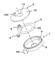
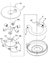
- FIG. 2 is an exploded perspective view of main components of the rotary connector according to the first embodiment of the present invention.
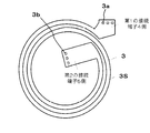
- 3A is a plan view of the wiring cable according to the first embodiment of the present invention, and
- FIG. 3B is a schematic cross-sectional view taken along the line AA of FIG. 3A.
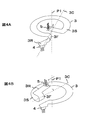
- 4A and 4B are perspective views of the wiring cable according to the first embodiment of the present invention.
- 5 and 6 are diagrams illustrating the operation of the wiring cable in the stator of the rotary connector according to the first embodiment of the present invention.
- FIG. 7 is a front view of the wiring cable 3 shown in FIG.
- the rotary connector includes a stator 1, a rotor 2 rotatably connected to the stator 1, and an annular shape existing between the stator 1 and the rotor 2. It is mainly configured by the wiring cable 3 housed in the space S.
- the rotor 2 rotates around the first virtual rotation axis P1.
- the direction extending the first virtual rotation axis P1 is referred to as a connector thickness direction D.
- the wiring cable 3 has a first connection terminal 4 fixed to the stator 1 and a second connection terminal 5 fixed to the rotor 2.
- the wiring cable 3 is formed by bending one end of the wiring cable 3a and integrally forming the wiring cable 3b therein.
- the wiring cable 3 is accommodated in a closed annular space S formed by the stator 1 and the rotor 2 shown in FIGS. 5 and 6.
- the rotary connector of the present embodiment is used by being assembled in a steering device of an automobile, and is electrically connected between a stator 1 installed on a steering column (not shown) and a rotor 2 connected to a handle (not shown). Connection is performed by the wiring cable 3.
- the stator 1 is roughly constituted by an outer cylindrical body 8 and a bottom plate member 9 made of synthetic resin, and the substantially cylindrical outer cylindrical body 8 is a substantially annular bottom plate member 9. It is integrated with the outer periphery.
- a fixed-side connection portion 50 that incorporates the first connection terminal 4 is integrally formed at a predetermined location on the outer peripheral surface side of the outer cylindrical body 8. The first connection terminal 4 incorporated in the fixed side connection portion 50 is fixed to the land portion 3a provided at one end of the wiring cable 3 shown in FIG. Electrically connected.
- the rotor 2 includes an upper rotor 13 and an intermediate rotor 14 made of synthetic resin, and the intermediate rotor 14 is integrated with the upper rotor 13.
- the upper rotor 13 has an annular top plate portion that faces the bottom plate member 9, and the intermediate rotor 14 has an inner cylinder portion that hangs down from the center of the top plate portion.
- the inner diameter is set to a dimension that allows a steering shaft (not shown) to be inserted.
- a movable side connection portion 13 c that incorporates the second connection terminal 5 is integrally formed on the top plate portion of the upper rotor 13.
- the second connection terminal 5 incorporated in the movable side connection portion 13c is fixed by soldering to a land portion 3b provided at the other end of the wiring cable 3 shown in FIG. 3A. And are electrically connected.
- the intermediate rotor 14 is formed in a substantially cylindrical shape through which the steering shaft can be inserted, and a lower rotor (not shown) is snap-coupled to an inner cylinder portion (not shown).
- the lower rotor is slidably engaged with the inner peripheral edge of the bottom plate member 9 so that the rotor 2 is rotatably connected to the stator 1.
- the wiring cable 3 is a spiral FPC (flexible printed circuit board) in a plan view, and a strip-shaped conductor layer 19 that is disposed between both ends in the longitudinal direction and that transmits signals is provided. It has the structure coat
- the side fixed to the stator (the first connection terminal 4 side) is a spiral outer peripheral side formed by the wiring cable 3.
- the side fixed to the rotor (the second connection terminal 5 side) has a shape protruding to the inner peripheral side of the spiral shape formed by the wiring cable 3.
- a land portion 3a in which the conductor layer is exposed in a circular shape by a circular hole provided in the insulating film is provided at an end portion of the wiring cable 3 on the first connection terminal 4 side, and a second portion is provided.
- a land portion 3b having the same configuration is provided at the end of the connection terminal 5 side. Since the land portion 3a is soldered with the first connection terminal 4 and the land portion 3b is soldered with the second connection terminal 5, the first connection terminal 4 and the second connection terminal 5 are different from each other. They are electrically connected via the conductor layer 19.
- FIG. 4A is a diagram illustrating a state in which the wiring cable 3 is folded back on the first connection terminal 4 side.
- FIG. 4B is a diagram illustrating a state in which the wiring cable 3 is folded back on the second connection terminal 5 side.
- the back surfaces 3R or the front surfaces 3S face each other, the facing surfaces are separated from each other in the connector thickness direction D in which the first virtual rotation axis P1 extends, and the connector thickness direction D And are arranged orthogonally.
- the central axis 3C of the folded portion 3F may be disposed so as to be perpendicular to the rotation axis P1 of the rotor 2.
- FIG. 6 shows a state in which the handle is cut clockwise (CW) from the position of FIG. 5 toward the paper surface, and the folded portion 3F and the second connection terminal 5 rotate clockwise (CW) toward the paper surface. Has moved. Further, the first connection terminal 4 (not shown) of the wiring cable 3 is incorporated in the fixed-side connection portion 50 of the stator 1, and the position does not change even when the handle is cut.
- the wiring cable 3 has a folded portion 3 ⁇ / b> F that is folded back so that the surfaces 3 ⁇ / b> S are opposed to each other. They are separated from each other in the connector thickness direction D in which the first virtual rotation axis P1 extends, and are arranged orthogonal to the connector thickness direction D. For this reason, the curvature of the R portion formed by the folding is not influenced by the radial width of the annular space S existing between the outer cylindrical portion and the inner cylindrical portion, and the folding is performed even if the width of the annular space S is narrowed. It is not necessary to reduce the curvature of the folded portion 3F formed by the above. As a result, even if the radial width of the annular space S existing between the stator 1 and the rotor 2 is reduced, the load applied to the folded portion 3F is not increased, and the possibility that the wiring cable 3 is disconnected is reduced. Can do.
- the wiring cable 3 is used to transmit electrical signals from an air bag system and a horn circuit, electrical signals from various steering switches, and to energize the steering heater. Since the steering heater requires a relatively large current, the wiring cable 3 for energizing the steering heater and the wiring cable 3 for transmitting other electrical signals are divided into the stator 1 and the rotor. You may comprise so that it may arrange
- the rotary connector according to this embodiment is fixed to the stator 1, the rotor 2 rotatably connected to the stator 1, the first connection terminal 4 fixed to the stator 1, and the rotor 2.
- a wiring cable 3 disposed in an annular space S existing between the stator 1 and the rotor 2.
- the wiring cable 3 has a spiral shape in plan view, and has a folded portion 3F that is folded back so that the front surfaces 3S or the back surfaces 3R face each other.
- the surfaces 3S which oppose are spaced apart in the connector thickness direction D from which the 1st virtual rotating shaft P1 extends.
- the wiring cable 3 of the rotary connector according to the present embodiment has a stripe shape, and the thickness direction is in the annular space S so as to be parallel to the connector thickness direction D in which the first virtual rotation axis P1 extends. Is arranged. Therefore, the surfaces 3S of the folded portion 3F can be opposed to each other on both sides of the folded portion 3F formed by folding.
- the wiring cable 3 of the rotary connector according to the present embodiment is composed of a flexible printed board including a conductor layer for transmitting a signal and an insulating layer made of a polyimide film covering the conductor layer from both sides.
- the conductor layer can be finely processed by etching, and a large number of conductor layers serving as signal lines can be formed. For this reason, even if the necessary signal lines increase, it is not necessary to increase the width of the wiring cable 3, and the wiring cable 3 having the same width is interposed between the outer cylinder portion of the stator 1 and the inner cylinder portion of the rotor 2. It can be arranged in the existing annular space S.
- the wiring cable 3 of the rotary connector according to the present embodiment is folded back on the first connection terminal 4 side as shown in FIG. 4A, for example.
- the assembly is preferable. .
- the wiring cable 3 of the rotary connector according to the present embodiment is folded on the second connection terminal 5 side as shown in FIG. 4B, for example.
- the assembly is preferable. Become.
- FIG. 7 is a plan view of a wiring cable according to a modification of the first embodiment of the present invention.
- FIG. 8 is a perspective view of the wiring cable according to the embodiment shown in FIG.
- the wiring cable 3 according to the first embodiment described with reference to FIGS. 1 to 7 is an FPC (flexible printed circuit board) having a single spiral shape in plan view, and a strip conductor is formed by an insulating film made of polyimide. It had a coated configuration.
- the wiring cable 3 of this modification is an FPC (flexible printed circuit board) having a double spiral shape in plan view, and the strip-shaped conductor layers are double-sided by an insulating layer made of a polyimide film. It has the structure coated from.
- the side fixed to the stator 1 (the first connection terminal 4 side) of both ends in the longitudinal direction of the wiring cable 3 is for wiring Projecting to the outer peripheral side of the spiral shape formed by the cable 3, the side fixed to the rotor 2 (second connection terminal 5 side) protrudes to the inner peripheral side of the spiral shape formed by the wiring cable 3. It has a shape.
- FIG. 8 is a diagram illustrating a state in which the wiring cable 3 is folded back on the first connection terminal 4 side.
- the movable range of the movable housing 2 can be increased. (Movable angle) can be increased.
- the wiring cable 3 has a double spiral shape in plan view, but the spiral is not limited to double.
- 8 shows a form in which the wiring cable 3 is folded back on the first connection terminal 4 side. However, as shown in FIG. 4B, the wiring cable 3 is folded back on the second connection terminal 5 side. You may comprise.
- the wiring cable 3 becomes narrow by making the wiring cable 3 into a double spiral shape in a plan view
- the wiring cable 3 is formed from a flexible printed circuit board whose insulating layer is made of polyimide. Become.
- the conductor layer can be finely processed by etching, and even if the width of the wiring cable 3 is reduced by forming the wiring cable 3 in a double spiral shape in a plan view, the necessary number of signals is ensured. can do.
- Other effects are the same as those of the rotary connector according to the embodiment described with reference to FIGS.
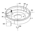
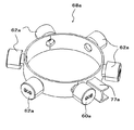
- FIG. 9 is an exploded perspective view of main components of the rotary connector according to the second embodiment of the present invention.
- FIG. 10 is a diagram for explaining the positional relationship among the wiring cable 3, the first guide roller 60, and the second guide roller 62 in the rotary connector shown in FIG.
- FIG. 11 is an external perspective view of the rotary connector shown in FIG. 9 with the rotor 2 removed.
- the rotary connector of the present embodiment is similar to the rotary connector of the first embodiment, in which the stator 1, the rotor 2, the wiring cable 3, the first connection terminal 4, and the second connection terminal 5. And a first guide roller 60, a second guide roller 62, and a guide roller support member 68.
- the rotary connector of the present embodiment has a folded portion 3F (R portion) that is folded back so that the back surfaces 3R or the front surfaces 3S of the wiring cable 3 face each other, as in the first embodiment.
- the back surfaces 3R or the front surfaces 3S face each other, the facing surfaces are separated from each other in the connector thickness direction D in which the first virtual rotation axis P1 extends, and the connector thickness direction D And are arranged orthogonally.
- the central axis 3C of the folded portion 3F may be disposed so as to be perpendicular to the rotation axis P1 of the rotor 2.
- the rotary connector of the present embodiment has a first guide roller 60 between the two opposing surfaces in the vicinity of the folded portion 3F.
- the first guide roller 60 guides the folded portion 3F when the rotor 2 rotates in a predetermined rotation direction.
- the first guide roller 60 is supported (inserted) in a first holder 70 formed on the guide roller support member 68 so as to be rotatable about the second virtual rotation axis P2.
- the guide roller support member 68 is formed with a guide portion 77 that guides the folded portion 3F.
- the guide roller support member 68 is positioned in the annular space S so as to be rotatable relative to the stator 1 and the rotor 2.
- the second virtual rotation axis P2 coinciding with the central axis of the first holder 70 is substantially orthogonal to the direction (connector thickness direction D) in which the first virtual rotation axis P1 extends.
- the second virtual rotation axis P2 is orthogonal to the first virtual rotation axis P1.
- a plurality of second holders 72 are formed on the guide roller support member 68 at predetermined intervals in the circumferential direction.
- a second guide roller 62 is rotatably supported (inserted) on the second holder 72.
- the second guide roller 62 is located in a region other than between the two opposed surfaces in the vicinity of the folded portion 3F of the wiring cable 3 in the annular space S.
- the spiral wiring cable 3 is guided by the first guide roller 60 and the second guide roller 62, so that the connector thickness direction D in which the first virtual rotation axis P1 extends.
- the wiring cable 3 can be stably positioned at the predetermined position. Therefore, even if the rotor 2 rotates, the wiring cable 3 can be moved smoothly.
- the folded portion 3F can be stably held by guiding the folded portion 3F with the first guide roller 60, and the folded portion that causes a malfunction in the operation of the rotary connector. It is possible to effectively suppress the occurrence of 3F twist and the like.
- the second virtual rotation axis P2 of the first guide roller 60 is orthogonal to the connector thickness direction D parallel to the first virtual rotation axis P1,
- the first guide roller 60 can be held in a posture suitable for the movement of the folded portion 3F of the wiring cable 3. Thereby, it can avoid that a malfunction arises in operation
- the number of parts can be reduced and a stable operation can be realized by using the guide roller support member 68 on which the first holder 70 and the second holder 72 are formed. .
- the second guide roller 62 is provided in the annular space S in a region other than between the two opposing surfaces in the vicinity of the folded portion 3F of the wiring cable 3. It is rotatably supported by 68 second holders 72.
- the spiral wiring cable 3 can be stably positioned at a predetermined position in the connector thickness direction D even at a portion other than the folded portion 3F of the wiring cable 3, and even if the rotor 2 rotates, the wiring The cable 3 can be moved smoothly.
- FIG. 12 illustrates the positional relationship among the wiring cable 3a, the first guide roller 60a, the second guide roller 62a, and the guide roller support member 68a in the rotary connector according to the second modification of the second embodiment.
- FIG. FIG. 13 is an external perspective view of a state in which the first guide roller 60a and the second guide roller 62a are mounted on the guide roller support member 68a shown in FIG.
- FIG. 14 is an external perspective view of the guide roller support member 68a shown in FIG.
- FIG. 15 is a plan view of the guide roller support member 68a shown in FIG.
- FIG. 16 is a plan view for explaining the posture of the first guide roller 60a of the guide roller support member 68a shown in FIG.
- the rotary connector according to this modification differs from the second embodiment in the attitude (inclination) of the first holder 70a of the guide roller support member 68a.
- the other configuration is basically the same as that of the second embodiment.
- the wiring cable 3 When the wiring cable 3 is disposed in the annular space S existing between the stator 1 and the rotor 2, as shown in FIG. 12, the wiring cable 3 is folded back so that the back surfaces 3R or the front surfaces 3S face each other. A folded portion 3F (R portion).
- the back surfaces 3R or the front surfaces 3S face each other, the facing surfaces are separated from each other in the connector thickness direction D in which the first virtual rotation axis P1 extends, and the connector thickness direction D And are arranged orthogonally.
- the first guide roller 60a is provided such that the width direction of the outer peripheral surface 60a1 and the width direction of the folded portion 3F that contacts the outer peripheral surface 60a1 are parallel to each other. That is, the first holder 70a of the guide roller support member 68a is formed so that the first guide roller 60a inserted into the first holder 70a has the above-described posture.
- the guide roller support member 68a is formed with a guide portion 77a for guiding the folded portion 3F, and the guide surface that guides the folded portion 3F so as to face the curved surface of the folded portion 3F has a predetermined gap. Are provided in parallel.
- the second virtual rotation axis P2a1 of the first guide roller 60a and the first holder 70a is orthogonal to the connector thickness direction D and is separated from the first virtual rotation axis P1.
- the second virtual rotation axis P2a2 of the second guide roller 62a and the second holder 72a is orthogonal to the connector thickness direction D and is orthogonal to the first virtual rotation axis P1.
- the first holder 70a, the guide portion 77a, and the guide roller support member 68a are defined, so that the inner surface of the folded portion 3F faces the outer peripheral surface 60a1 of the first guide roller 60a. Since the outer surface of the folded portion 3F comes into surface contact with the guide surface of the guide portion 77a, it is stably guided from both sides by the first guide roller 60a and the guide surface of the guide portion 77a. Can be avoided. Thereby, consumption of the folding
- FIG. 17 is a view for explaining a guide roller support member 268 of a third modification of the second embodiment.
- 18 is a cross-sectional view of the connecting portion of the guide roller support member 268 shown in FIG.
- the guide roller support member 268 one first holder and a plurality of second holders are formed at predetermined intervals on a strip-like plate-like member 280 before the state shown in FIG. Yes.
- a first coupling portion 210 is provided at one end of the plate-like member 280, and a second coupling portion 212 is provided at the other end.
- the guide roller support member 268 bends the plate-like member 280 into a ring shape and connects the first coupling portion 210 and the second coupling portion 212 to obtain the shape of FIG.
- the first holder and the second holder are supported by the first holder between the two opposing surfaces of the folded portion 3F in the annular space S.
- the first guide roller 60 is located.
- the second guide roller 62 supported by the second holder is located in a region other than between the two opposing surfaces of the folded portion 3F of the wiring cable 3 in the annular space S.
- the first coupling portion 210 and the second coupling portion 212 are connected to each other between a concave portion 210 a of the first coupling portion 210 and a convex portion 212 a of the second coupling portion 212. Realized by integration.
- the first holder and the second holder extend in one direction before the ring-shaped plate member 280 is bent to form the ring portion. Because there is a holder opening on the same side as the annular opening of the guide roller support member 268, the mold does not require a slide structure, and the mold can be configured simply and inexpensively. The manufacturing process can be simplified.
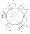
- FIG. 19 is a view for explaining the positional relationship among the wiring cable 3, the first guide roller 60 b, the second guide roller 62 b, and the guide roller support member 468 in the rotary connector according to the fourth modification of the second embodiment.
- FIG. 20 is an external perspective view of the guide roller support member 468 shown in FIG.
- FIG. 21 is a plan view of the guide roller support member 468 shown in FIG. 22 is an external perspective view of the first ring constituting portion 491 constituting the guide roller support member 468 shown in FIG.
- the rotary connector according to this modification is characterized by a guide roller support member 468.
- the guide roller support member 468 has a ring shape in which one first ring constituent portion 491 and five second ring constituent portions 492 are arranged along the circumferential direction and connected to each other via a connecting portion 410. Is formed.
- a first holder 70b is formed in the first ring component 491, and the first guide roller 60b is inserted into the first holder 70b.
- a guide portion 477 that guides the folded portion 3F is formed in the first ring constituting portion 491.
- Each of the five second ring components 492 is formed with a second holder 72b, and the second guide roller 62b is inserted into the second holder 72b.
- the first guide roller 60b has a width direction of the outer peripheral surface 60b1 and a width direction of the folded portion 3F that contacts the outer peripheral surface 60b1. Is provided. That is, the first holder 70b of the guide roller support member 468 is formed so that the first guide roller 60b inserted into the first holder 70b has the above-described posture.
- the second virtual rotation axis P2b1 of the first guide roller 60b and the first holder 70b is orthogonal to the connector thickness direction D and is separated from the first virtual rotation axis P1.
- the second virtual rotation axis P2b2 of the second guide roller 62b and the second holder 72b is orthogonal to the connector thickness direction D and is orthogonal to the first virtual rotation axis P1.
- the guide roller support member 468 is formed in order to form the guide roller support member 468 by combining one first ring component 491 and five second ring components 492. Therefore, the mold used for the purpose can be reduced in size.
- the number of the 1st ring structure part 491 and the 5 2nd ring structure part 492 is not limited.
- the guide roller support member 468 may be formed using only one of the first ring component 491 and the second ring component 492.
- a plurality of wiring cables 3 are provided on the rotation axis P1 of the rotor 2 in the annular space S existing between the outer cylinder portion of the stator 1 and the inner cylinder portion of the rotor 2. They are arranged so as to be parallel to each other. For this reason, it is possible to cope with an increase in the number of necessary signal lines. Further, a wiring cable 3 for energizing a steering heater that requires a relatively large current and a wiring cable 3 for transmitting other electrical signals are separated and exist between the stator 1 and the rotor 2. It can be arranged in the annular space S.
- first guide roller 60 and five second guide rollers 62 are formed on the guide roller support member 68 is exemplified.
- the number of guide rollers 62 is arbitrary. Further, only one of the first guide roller 60 and the second guide roller 62 may be used.
- the case where the holder for supporting a plurality of guide rollers is provided on one guide roller support member 68 is exemplified.
- the plurality of guide rollers are supported on the plurality of guide roller support members. May be.
- the case where the second virtual rotation axis P2 of the first guide roller 60 and the second guide roller 62 is orthogonal to the connector thickness direction D is exemplified. You may comprise so that it may cross
Landscapes
- Electric Cable Arrangement Between Relatively Moving Parts (AREA)
- Steering Controls (AREA)
Abstract
La présente invention comprend : un stator (1) comportant une partie cylindrique extérieure ; un rotor (2) qui est accouplé en rotation au stator (1) ; et un fil de câblage (3) qui comporte une première borne de connexion (4) fixée au stator (1) et une seconde borne de connexion (5) fixée au rotor (2), et qui est disposé à l'intérieur d'un espace annulaire (S) entre le stator (1) et le rotor (2), le fil de câblage (3) étant formé dans une configuration en spirale, et comportant une partie de repli (3F) dans laquelle le fil de câblage est replié de manière que des parties de sa surface avant (3S) ou des parties de sa surface arrière (3R) soient en regard l'une de l'autre.
Applications Claiming Priority (2)
| Application Number | Priority Date | Filing Date | Title |
|---|---|---|---|
| JP2015-247015 | 2015-12-18 | ||
| JP2015247015 | 2015-12-18 |
Publications (1)
| Publication Number | Publication Date |
|---|---|
| WO2017104548A1 true WO2017104548A1 (fr) | 2017-06-22 |
Family
ID=59056563
Family Applications (1)
| Application Number | Title | Priority Date | Filing Date |
|---|---|---|---|
| PCT/JP2016/086621 WO2017104548A1 (fr) | 2015-12-18 | 2016-12-08 | Connecteur rotatif |
Country Status (1)
| Country | Link |
|---|---|
| WO (1) | WO2017104548A1 (fr) |
Citations (4)
| Publication number | Priority date | Publication date | Assignee | Title |
|---|---|---|---|---|
| GB2164506A (en) * | 1984-09-12 | 1986-03-19 | Mcgeoch & Co William | Coupling device between relatively rotatable members |
| JPH02215071A (ja) * | 1989-02-14 | 1990-08-28 | Furukawa Electric Co Ltd:The | コネクタ装置 |
| JPH0321544A (ja) * | 1989-06-15 | 1991-01-30 | Daihatsu Motor Co Ltd | 配線装置 |
| WO2014008644A1 (fr) * | 2012-07-11 | 2014-01-16 | Abb Technology Ltd | Unité de câblage à joint rotatif |
-
2016
- 2016-12-08 WO PCT/JP2016/086621 patent/WO2017104548A1/fr active Application Filing
Patent Citations (4)
| Publication number | Priority date | Publication date | Assignee | Title |
|---|---|---|---|---|
| GB2164506A (en) * | 1984-09-12 | 1986-03-19 | Mcgeoch & Co William | Coupling device between relatively rotatable members |
| JPH02215071A (ja) * | 1989-02-14 | 1990-08-28 | Furukawa Electric Co Ltd:The | コネクタ装置 |
| JPH0321544A (ja) * | 1989-06-15 | 1991-01-30 | Daihatsu Motor Co Ltd | 配線装置 |
| WO2014008644A1 (fr) * | 2012-07-11 | 2014-01-16 | Abb Technology Ltd | Unité de câblage à joint rotatif |
Similar Documents
| Publication | Publication Date | Title |
|---|---|---|
| JPH0321544A (ja) | 配線装置 | |
| EP2685571B1 (fr) | Dispositif de connexion rotatif | |
| US7393222B2 (en) | Rotatable connector | |
| EP2078640B1 (fr) | Connecteur rotatif | |
| EP2571126B1 (fr) | Dispositif de connecteur rotatif | |
| US8911239B2 (en) | Rotatable connector device | |
| US9070496B2 (en) | Rotatable connector device | |
| JP2011258546A5 (fr) | ||
| EP2555346B1 (fr) | Dispositif raccord rotatif | |
| US20140235082A1 (en) | Rotatable connector device | |
| EP1180831B1 (fr) | Connecteur rotatif capable d'augmenter largement la hauteur de l'espace pour le logement du câble flexible | |
| WO2017104548A1 (fr) | Connecteur rotatif | |
| GB2328330A (en) | Clockspring connector | |
| JP6636628B2 (ja) | 回転コネクタ | |
| JP2010009849A (ja) | 回転コネクタ装置 | |
| JP5342866B2 (ja) | 回転コネクタ装置 | |
| KR102169773B1 (ko) | 회전 커넥터 장치 | |
| JP6608294B2 (ja) | 回転コネクタ | |
| JP5630905B2 (ja) | ロールコネクタ装置及びロールコネクタ断線検知装置 | |
| JP5557677B2 (ja) | ロールコネクタ断線検知装置 | |
| JP2020170644A (ja) | 回転コネクタ | |
| JP2000123938A (ja) | 回転接続装置 | |
| MXPA97005329A (en) | Rotary connector |
Legal Events
| Date | Code | Title | Description |
|---|---|---|---|
| 121 | Ep: the epo has been informed by wipo that ep was designated in this application |
Ref document number: 16875528 Country of ref document: EP Kind code of ref document: A1 |
|
| NENP | Non-entry into the national phase |
Ref country code: DE |
|
| 122 | Ep: pct application non-entry in european phase |
Ref document number: 16875528 Country of ref document: EP Kind code of ref document: A1 |
|
| NENP | Non-entry into the national phase |
Ref country code: JP |