WO2017104490A1 - 状態推定装置及び状態推定方法 - Google Patents
状態推定装置及び状態推定方法 Download PDFInfo
- Publication number
- WO2017104490A1 WO2017104490A1 PCT/JP2016/086259 JP2016086259W WO2017104490A1 WO 2017104490 A1 WO2017104490 A1 WO 2017104490A1 JP 2016086259 W JP2016086259 W JP 2016086259W WO 2017104490 A1 WO2017104490 A1 WO 2017104490A1
- Authority
- WO
- WIPO (PCT)
- Prior art keywords
- motor
- state
- state estimation
- inductor
- voltage
- Prior art date
- Legal status (The legal status is an assumption and is not a legal conclusion. Google has not performed a legal analysis and makes no representation as to the accuracy of the status listed.)
- Ceased
Links
Images


Classifications
-
- H—ELECTRICITY
- H02—GENERATION; CONVERSION OR DISTRIBUTION OF ELECTRIC POWER
- H02P—CONTROL OR REGULATION OF ELECTRIC MOTORS, ELECTRIC GENERATORS OR DYNAMO-ELECTRIC CONVERTERS; CONTROLLING TRANSFORMERS, REACTORS OR CHOKE COILS
- H02P7/00—Arrangements for regulating or controlling the speed or torque of electric DC motors
- H02P7/06—Arrangements for regulating or controlling the speed or torque of electric DC motors for regulating or controlling an individual DC dynamo-electric motor by varying field or armature current
- H02P7/18—Arrangements for regulating or controlling the speed or torque of electric DC motors for regulating or controlling an individual DC dynamo-electric motor by varying field or armature current by master control with auxiliary power
- H02P7/24—Arrangements for regulating or controlling the speed or torque of electric DC motors for regulating or controlling an individual DC dynamo-electric motor by varying field or armature current by master control with auxiliary power using discharge tubes or semiconductor devices
- H02P7/28—Arrangements for regulating or controlling the speed or torque of electric DC motors for regulating or controlling an individual DC dynamo-electric motor by varying field or armature current by master control with auxiliary power using discharge tubes or semiconductor devices using semiconductor devices
- H02P7/285—Arrangements for regulating or controlling the speed or torque of electric DC motors for regulating or controlling an individual DC dynamo-electric motor by varying field or armature current by master control with auxiliary power using discharge tubes or semiconductor devices using semiconductor devices controlling armature supply only
Definitions
- the present invention relates to a state estimation device and a state estimation method for estimating a state of a control target.
- the angle of the robot part is estimated by identifying the inductance of an actuator (motor) that drives the robot.
- an actuator motor
- it is necessary to superimpose an input for inductance estimation on an input necessary for control which causes problems in control performance and estimation accuracy.
- the structure is such that the inductance varies depending on the angle, the applicable actuator structure is limited.
- An object of the present invention is to more appropriately estimate the state of a controlled object without using a sensor.
- a state estimation device includes: A power source that supplies power to a motor to be controlled and an inductor connected in series to a circuit that connects the motor; Voltage detecting means for detecting a voltage across the inductor; Estimating means for estimating the state of the motor based on the voltage across the inductor detected by the voltage detecting means; It is characterized by providing.
- the state of the controlled object can be estimated more appropriately without using a sensor.
- FIG. 3 (A) is a figure which shows the estimation result of a force
- FIG.3 (B) is a figure which shows the estimation result of a torque.
- FIG. 1 is a circuit diagram showing the basic principle of the present invention.
- a circuit including a power source 10, a control target 20, and a state estimation inductor 30 is configured in the state estimation device 1 according to the present invention.
- the power supply 10 and the state estimation inductor 30 can be installed on the control side away from the controlled object 20.
- the power supply 10 and the state estimating inductor 30 can be installed in a control room or the like in an accessible environment.
- a power supply 10 is a power supply whose supply voltage is variable, and supplies power according to the load of the control target 20.
- the control target 20 is configured by, for example, an actuator (motor) or the like, and operates with electric power supplied from the power supply 10.
- the control target 20 generates a counter electromotive force according to the load during operation.
- the state estimation inductor 30 is connected in series to a loop including the power supply 10 and the control target 20, and the same current as the current flowing through the power supply 10 and the control target 20 (hereinafter referred to as “drive current” as appropriate) flows. It has become.
- the state estimation inductor 30 generates an electromotive force according to the self-inductance when a drive current flows.
- Expression (2) is expressed as Expression (4).
- Vm R ⁇ I + Kt ⁇ ⁇ (4)
- Expression (5) is obtained by differentiating both sides of Expression (4) with respect to time. It is done.
- dVm R ⁇ dI + Kt ⁇ d ⁇ (5)
- ⁇ Vm is the amount of change in the supply voltage of the power supply 10 (that is, the amount of change in the command value to the power supply 10)
- VL is the voltage across the state estimation inductor 30 (measured value).
- robust control such as a disturbance observer using the angular acceleration d ⁇ of the controlled object 20.
- robust control can be performed by obtaining the angular acceleration d ⁇ of the control target 20, so that the position and force of the control target 20 can be controlled with high accuracy.
- the external force applied to the controlled object 20 can be estimated by a disturbance observer or the like, an angle control loop based on the angular acceleration and a torque control loop based on the estimated external force can be configured.
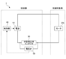
- FIG. 2 is a block diagram showing a specific configuration of the state estimation apparatus 1 to which the present invention is applied.
- the state estimation device 1 includes a power supply 10, a motor 20 a as a control target 20, a state estimation inductor 30, a control unit 40, and a voltmeter 50.
- the power supply 10 and the state estimation inductor 30 are referred to the description in FIG. 1, and the description is omitted here.
- the motor 20a is, for example, an actuator that drives a robot manipulator, and outputs a force corresponding to the power supplied from the power supply 10 to the outside. Further, the motor 20a is installed at a position remote from the power source 10, the state estimation inductor 30, the control unit 40, and the voltmeter 50 (a point separated by a distance or a point separated by an obstacle such as a wall). . However, in the present invention, the distance from the power source 10 or the like to the motor 20a is not particularly questioned.
- the control unit 40 controls the power supply 10 by inputting a command value of power supplied from the power supply 10.
- the control unit 40 estimates the angular acceleration d ⁇ (or force to be output) of the motor 20a based on the equation (8) based on the voltage VL across the state estimation inductor 30 input from the voltmeter 50, A command value of power supplied from the power supply 10 is determined.
- the voltmeter 50 measures the voltage VL across the state estimating inductor 30 and outputs the measurement result to the control unit 40. Note that the both-ends voltage VL of the state estimation inductor 30 measured by the voltmeter 50 is A / D (Analog to Digital) converted and output to the control unit 40.
- the control unit 40 calculates a command value to the power source 10 corresponding to the target value of the force (or position) output from the motor 20 a and inputs the command value to the power source 10. Then, the power supply 10 applies a voltage Vm corresponding to the command value to the motor 20a, and the motor 20a outputs a force (or position) according to the applied voltage Vm. At this time, a current I that is common to the power supply 10, the motor 20a, and the state estimation inductor 30 flows through the state estimation device 1, and the control unit 40 controls the internal resistance R of the motor 20a, the back electromotive force constant Kt, and the state estimation. inductance L of the inductor 30, and calculates the angular acceleration d ⁇ corresponding across voltage V L variation ⁇ Vm and state estimation inductor 30 of the supply voltage of the power source 10 (see equation (8)).
- each acceleration d ⁇ it is possible to appropriately estimate the state of the motor 20a such as speed (integration of acceleration), position (double integration of acceleration) or force. That is, the state of the motor 20a can be estimated more appropriately without using a sensor.
- the manipulator of the robot by bilateral control while reproducing the force sense in the motor 20a on the control side and transmitting the accurate force sense.
- the present invention is used for bilateral control, the difference in acceleration between the master side and the slave side becomes substantially zero, and the force sense is appropriately transmitted.
- the absolute positions on the master side and the slave side are operated by the operator while visually recognizing the position with a camera or the like, so that there is no problem in transmitting the force sense.
- the state estimation device 1 estimates the state of the motor 20a without using a sensor and resets the state of the motor 20a in order to reset the accumulated error that occurs when estimating the state of the motor 20a. It is also possible to provide a reset sensor (detection means) for detection. In this case, it is sufficient that the sensor for resetting is a sensor having a coarser detection accuracy than a sensor for detecting the state of the motor 20a as in the prior art. Since the reset sensor is a sensor with a coarser detection accuracy, even if it is installed in a poor environment, the influence of the environment on the estimation accuracy is smaller than the conventional sensor that detects the state of the motor 20a. Become.
- the reset sensor since the reset sensor only needs to be able to reset the accumulated error, it is possible to use a sensor of a different type from the conventional sensor that detects the state of the motor 20a. Therefore, a type of sensor that is not easily affected by the environment in which the motor 20a is installed can be selected as a reset sensor. Thus, by providing the reset sensor, higher estimation accuracy can be realized.
- FIG. 3A and 3B are schematic diagrams showing experimental results when the state is estimated using the present invention
- FIG. 3A is a diagram showing a force estimation result
- FIG. 3B is a diagram showing a torque estimation result.
- the measured value (dotted line) measured using the sensor and the estimated value (dashed line) estimated using the present invention are almost equal.
- Match As shown in FIG. 3B, with respect to the torque command value (solid line), a measured value (dotted line) measured using a sensor and an estimated value (dashed line) estimated using the present invention Is almost the same.
- the present invention it is possible to more appropriately estimate the state of the controlled object without using a sensor. Therefore, according to the present invention, failure and false detection of the sensor unit are eliminated, so that the fault tolerance can be improved, and the volume corresponding to the sensor is not required, so that the apparatus can be downsized. Further, according to the present invention, since the weight corresponding to the sensor is eliminated, the weight of the device can be reduced, and the cost for installing the sensor is not required, so that the cost of the device can be reduced.
- the present invention realizes high-precision control of position and force without arranging a sensor on the drive side, and improves fault tolerance and cost reduction that the current robot technology has, and downsizing the apparatus. Such a problem can be solved. This makes it possible to use robots in the field that were difficult to introduce in the past and to develop cheaper robots, and is expected to be applied in a wide range of fields.
- the present invention can be applied to an actuator used inside a nuclear reactor. That is, a manipulator having an actuator can be arranged inside the nuclear reactor, and a manipulator control unit, a power source, and a state estimation inductance can be arranged in the nuclear reactor control room.
- a manipulator equipped with a sensor When a manipulator equipped with a sensor is used in a nuclear reactor, the sensor fails in a short period due to radioactivity, and it is necessary to frequently replace the manipulator.
- the configuration of the present invention it is possible to estimate the state of the manipulator in the same manner as in the case where the state of the manipulator is measured by the sensor, and to reduce the manipulator replacement frequency. .
- the present invention can be applied to an actuator used in a narrow space such as the inside of a human body. It is difficult to provide an encoder having a relatively large size in a manipulator used in a narrow space such as a manipulator used in endoscopic surgery inside a human body. In such a case, the force sense of the manipulator can be transmitted to the control unit side by applying the configuration of the present invention and arranging the state estimation inductor 30 in series with the actuator that drives the manipulator. It becomes.
- the current state (acceleration, velocity, position, etc.) of the actuator is used as an input, and the position (or velocity) or force
- the operation of the actuator can be determined by performing computation in at least one of the areas (see, for example, International Patent Application PCT / JP2014 / 073083 by the inventors).
- applying the present invention and providing the state estimation inductor 30 makes it possible to estimate the current position of the actuator without providing a sensor for detecting the current position of the actuator.
- the present invention can be applied to a motor that drives an excavator that performs excavation work of a tunnel or the like.
- tunnel excavation work it may hit hard layers such as bedrock due to changes in geology, and if it is dug as it is, it may cause malfunction of the excavator. Therefore, at the excavation site, the excavator is stopped as appropriate, and for example, several days are spent to check the formation. The efficiency of the construction work will be reduced due to such confirmation of the formation.
- the present invention to the motor that drives the excavator, the force output from the motor to the formation can be estimated in real time without providing a sensor.
- the state estimation device 1 configured as described above includes a power supply 10, a motor 20a, a state estimation inductor 30, a control unit 40, and a voltmeter 50.
- the state estimation inductor 30 is connected in series to a circuit connecting the power supply 10 that supplies power to the motor 20a to be controlled and the motor 20a.
- the voltmeter 50 detects the voltage across the inductor 30 for state estimation.
- the controller 40 estimates the state of the motor 20 a based on the voltage across the state estimating inductor 30 detected by the voltmeter 50.
- a current common to the power source 10, the motor 20 a, and the state estimation inductor 30 flows through the state estimation device 1, and the control unit 40 controls the motor 20 a based on the voltage across the state estimation inductor 30. Estimate the state. Therefore, the state of the motor 20a can be estimated more appropriately without using a sensor.
- the power supply 10, the state estimation inductor 30 and the motor 20a are installed at remote positions. Thereby, the state of the motor 20a can be estimated using the state estimation inductor 30 installed outside the poor environment or the like without providing the motor 20a installed in the poor environment or the like.
- control unit 40 estimates the state of the motor 20a based on the change in the command value of the voltage applied to the motor 20a and the voltage across the state estimation inductor 30. As a result, the state of the motor 20a can be estimated from the command value or measurement value that can be easily acquired.
- control part 40 estimates the angular acceleration or acceleration in the motor 20a. Thereby, it is possible to more appropriately estimate the angular acceleration or acceleration necessary for transmitting the force sense.
- control part 40 estimates the torque or force in the motor 20a. Thereby, it is possible to more appropriately control the force in the manipulator of the robot.
- the state estimation device 1 includes a reset sensor.
- the reset sensor detects the state of the motor 20a in order to reset the estimation error by the control unit 40.
- the control unit 40 resets the accumulated error when estimating the state of the motor 20a based on the detection result of the resetting sensor. Thereby, higher estimation accuracy can be realized in the state estimation device 1.
- the said embodiment has shown an example to which this invention is applied, and does not limit the technical scope of this invention. That is, the present invention can be modified in various ways such as omission and replacement without departing from the gist of the present invention, and can take various embodiments other than the above-described embodiments. Various embodiments that the present invention can take and modifications thereof are included in the invention described in the scope of claims and the equivalents thereof.
Landscapes
- Engineering & Computer Science (AREA)
- Power Engineering (AREA)
- Control Of Electric Motors In General (AREA)
- Control Of Direct Current Motors (AREA)
- Manipulator (AREA)
Abstract
センサを用いることなく制御対象の状態をより適切に推定すること。 状態推定装置1は、電源10と、モータ20aと、状態推定用インダクタ30と、制御部40と、電圧計50とを備える。状態推定用インダクタ30は、制御対象となるモータ20aに電力を供給する電源10と当該モータ20aとを接続する回路に直列に接続される。電圧計50は、状態推定用インダクタ30の両端電圧を検出する。制御部40は、電圧計50によって検出された状態推定用インダクタ30の両端電圧に基づいて、モータ20aの状態を推定する。
Description
本発明は、制御対象の状態を推定する状態推定装置及び状態推定方法に関する。
従来、耐故障性の向上やコストの低減、装置の小型化等の観点からロボット等におけるモータ(電動機)のセンサレス化が求められている。特に、センサの動作に影響を与える化学物質に汚染された環境や強い放射能が存在する環境等、ロボット等に備えられるモータを劣悪な環境下で稼動させる場合、センサによってモータの状態を把握することが困難であり、モータのセンサレス化は極めて重要な課題である。
ここで、ロボット等におけるモータのセンサレス化を図るために、インダクタンスの変化によりモータを備えるロボットの部位の角度を推定する技術が知られている(例えば、特許文献1参照)。
ここで、ロボット等におけるモータのセンサレス化を図るために、インダクタンスの変化によりモータを備えるロボットの部位の角度を推定する技術が知られている(例えば、特許文献1参照)。
しかしながら、特許文献1に記載された技術においては、ロボットを駆動するアクチュエータ(モータ)のインダクタンスを同定することで、ロボットの部位の角度を推定している。このような方法では、制御に必要となる入力に対し、インダクタンス推定のための入力を重畳する必要があり、制御性能や推定精度に課題が生じる。また、角度に依存してインダクタンスが変化する構造を前提としているため、適用可能なアクチュエータの構造が限定される。
このように、従来の技術においては、センサを用いることなく制御対象の状態を適切に推定することが困難であった。
このように、従来の技術においては、センサを用いることなく制御対象の状態を適切に推定することが困難であった。
本発明の課題は、センサを用いることなく制御対象の状態をより適切に推定することである。
上記課題を解決するため、本発明の一態様に係る状態推定装置は、
制御対象となるモータに電力を供給する電源と当該モータとを接続する回路に直列に接続されたインダクタと、
前記インダクタの両端電圧を検出する電圧検出手段と、
前記電圧検出手段によって検出された前記インダクタの両端電圧に基づいて、前記モータの状態を推定する推定手段と、
を備えることを特徴とする。
制御対象となるモータに電力を供給する電源と当該モータとを接続する回路に直列に接続されたインダクタと、
前記インダクタの両端電圧を検出する電圧検出手段と、
前記電圧検出手段によって検出された前記インダクタの両端電圧に基づいて、前記モータの状態を推定する推定手段と、
を備えることを特徴とする。
本発明によれば、センサを用いることなく制御対象の状態をより適切に推定することができる。
以下、本発明の実施形態について、図面を参照して説明する。
初めに、本発明に係る状態推定装置及び状態推定方法に適用される基本的原理について説明する。
[基本的原理]
図1は、本発明の基本的原理を示す回路図である。
図1に示すように、本発明に係る状態推定装置1においては、電源10と、制御対象20と、状態推定用インダクタ30とを含む回路が構成される。
これらのうち、電源10及び状態推定用インダクタ30は、制御対象20とは位置が離れた制御側に設置することができる。例えば、制御対象20が化学物質や放射能等のため立ち入り困難な環境に設置される場合、電源10及び状態推定用インダクタ30は、立ち入り可能な環境にある制御室等に設置することができる。
初めに、本発明に係る状態推定装置及び状態推定方法に適用される基本的原理について説明する。
[基本的原理]
図1は、本発明の基本的原理を示す回路図である。
図1に示すように、本発明に係る状態推定装置1においては、電源10と、制御対象20と、状態推定用インダクタ30とを含む回路が構成される。
これらのうち、電源10及び状態推定用インダクタ30は、制御対象20とは位置が離れた制御側に設置することができる。例えば、制御対象20が化学物質や放射能等のため立ち入り困難な環境に設置される場合、電源10及び状態推定用インダクタ30は、立ち入り可能な環境にある制御室等に設置することができる。
図1において、電源10は、供給する電圧が可変の電源であり、制御対象20の負荷に応じた電力を供給する。
制御対象20は、例えばアクチュエータ(モータ)等によって構成され、電源10から供給される電力によって動作する。なお、制御対象20は、動作時に負荷に応じた逆起電力を発生する。
状態推定用インダクタ30は、電源10及び制御対象20を含むループに直列に接続され、電源10及び制御対象20を流れる電流と同一の電流(以下、適宜「駆動電流」と呼ぶ。)が流れる構成となっている。状態推定用インダクタ30は、駆動電流が流れることにより、自己インダクタンスに応じた起電力を発生する。
制御対象20は、例えばアクチュエータ(モータ)等によって構成され、電源10から供給される電力によって動作する。なお、制御対象20は、動作時に負荷に応じた逆起電力を発生する。
状態推定用インダクタ30は、電源10及び制御対象20を含むループに直列に接続され、電源10及び制御対象20を流れる電流と同一の電流(以下、適宜「駆動電流」と呼ぶ。)が流れる構成となっている。状態推定用インダクタ30は、駆動電流が流れることにより、自己インダクタンスに応じた起電力を発生する。
図1に示すように、制御対象20(モータ)のイナーシャをJ、角速度をω、発生トルクをTm、負荷トルクをTlとすると、制御対象20の運動方程式は、式(1)によって表される。
J・dω=Tm-Tl (1)
ただし、dωはωの時間微分である。
J・dω=Tm-Tl (1)
ただし、dωはωの時間微分である。
また、制御対象20の印加電圧をVm、内部抵抗をR、電流をI、逆起電力をEとすると、制御対象20における電圧の関係は、式(2)によって表される。
Vm=R・I+E (2)
Vm=R・I+E (2)
ここで、式(2)における逆起電力Eは、逆起電力定Kt及び角速度ωを用いて、式(3)によって表される。
E=Kt・ω (3)
E=Kt・ω (3)
すると、式(2)は、式(4)のように表される。
Vm=R・I+Kt・ω (4)
制御対象20の内部抵抗及び逆起電力定数Ktの変化がきわめて微小であり、実質的に一定であるとみなせる場合、式(4)の両辺を時間で微分することで、式(5)が得られる。
dVm=R・dI+Kt・dω (5)
Vm=R・I+Kt・ω (4)
制御対象20の内部抵抗及び逆起電力定数Ktの変化がきわめて微小であり、実質的に一定であるとみなせる場合、式(4)の両辺を時間で微分することで、式(5)が得られる。
dVm=R・dI+Kt・dω (5)
式(5)を角速度について解くと、式(6)が得られる。
dω=(dVm-R・dI)/Kt (6)
制御対象20と直列に状態推定用インダクタ30を接続した場合、状態推定用インダクタ30のインダクタンスをLとすると、状態推定用インダクタ30に印加される電圧VLは、式(7)のように表される。
VL=L・dI (7)
dω=(dVm-R・dI)/Kt (6)
制御対象20と直列に状態推定用インダクタ30を接続した場合、状態推定用インダクタ30のインダクタンスをLとすると、状態推定用インダクタ30に印加される電圧VLは、式(7)のように表される。
VL=L・dI (7)
制御対象20に流れる電流と、状態推定用インダクタ30に流れる電流とは等しいことから、式(7)の電流微分値dIを(6)式に代入すると、式(8)が得られる。
dω=(ΔVm-R・(VL/L))/Kt
=(ΔVm・L-R・VL)/(Kt・L) (8)
dω=(ΔVm-R・(VL/L))/Kt
=(ΔVm・L-R・VL)/(Kt・L) (8)
式(8)において、ΔVmは電源10の供給電圧の変化量(即ち、電源10への指令値の変化量)、VLは状態推定用インダクタ30の両端電圧(測定値)である。
これにより、式(8)から、制御側において取得可能なパラメータ(ΔVm及びVL)によって、制御対象20の角加速度dωを推定することができる。
即ち、本発明の構成では、制御対象20の状態が、制御側に設置された状態推定用インダクタ30に反映されることから、状態推定用インダクタ30の状態に着目することで、制御対象20にセンサを備えることなく、制御側において制御対象20の状態を推定することができる。
これにより、式(8)から、制御側において取得可能なパラメータ(ΔVm及びVL)によって、制御対象20の角加速度dωを推定することができる。
即ち、本発明の構成では、制御対象20の状態が、制御側に設置された状態推定用インダクタ30に反映されることから、状態推定用インダクタ30の状態に着目することで、制御対象20にセンサを備えることなく、制御側において制御対象20の状態を推定することができる。
また、制御対象20の角加速度dωを用いて、外乱オブザーバ等のロバスト制御を構成することが可能となる。
また、制御対象20の角加速度dωが求められることにより、ロバスト制御を行うことが可能となるため、制御対象20の位置及び力を高精度に制御することができる。これにより、制御対象20に入力される力覚を制御側に伝達すること等が可能となり、遠隔操作されるロボットにおけるモータのセンサレス化を実現することができる。
さらに、外乱オブザーバ等により制御対象20に加わる外力を推定することができるため、角加速度に基づく角度制御ループ及び推定した外力に基づくトルク制御ループを構成することが可能となる。
また、制御対象20の角加速度dωが求められることにより、ロバスト制御を行うことが可能となるため、制御対象20の位置及び力を高精度に制御することができる。これにより、制御対象20に入力される力覚を制御側に伝達すること等が可能となり、遠隔操作されるロボットにおけるモータのセンサレス化を実現することができる。
さらに、外乱オブザーバ等により制御対象20に加わる外力を推定することができるため、角加速度に基づく角度制御ループ及び推定した外力に基づくトルク制御ループを構成することが可能となる。
[具体的構成]
次に、本発明を適用した状態推定装置1の具体的構成について説明する。
図2は、本発明を適用した状態推定装置1の具体的構成を示すブロック図である。
図2に示すように、状態推定装置1は、電源10と、制御対象20としてのモータ20aと、状態推定用インダクタ30と、制御部40と、電圧計50とを備えている。
これらのうち、電源10及び状態推定用インダクタ30は、図1における説明を参照することとし、ここでは説明を省略する。
次に、本発明を適用した状態推定装置1の具体的構成について説明する。
図2は、本発明を適用した状態推定装置1の具体的構成を示すブロック図である。
図2に示すように、状態推定装置1は、電源10と、制御対象20としてのモータ20aと、状態推定用インダクタ30と、制御部40と、電圧計50とを備えている。
これらのうち、電源10及び状態推定用インダクタ30は、図1における説明を参照することとし、ここでは説明を省略する。
モータ20aは、例えば、ロボットのマニピュレータを駆動するアクチュエータであり、電源10から供給された電力に応じた力を外部に出力する。また、モータ20aは、電源10、状態推定用インダクタ30、制御部40及び電圧計50とは遠隔的な位置(距離が離れた地点あるいは壁等の障害物に隔たれた地点等)に設置される。ただし、本発明において、電源10等からモータ20aまでの距離の遠近は特に問うものではない。
制御部40は、電源10から供給する電力の指令値を入力することにより、電源10を制御する。このとき、制御部40は、式(8)に基づいて、電圧計50から入力される状態推定用インダクタ30の両端電圧VLによってモータ20aの角加速度dω(あるいは出力する力)を推定し、電源10から供給する電力の指令値を決定する。
電圧計50は、状態推定用インダクタ30の両端電圧VLを測定し、測定結果を制御部40に出力する。なお、電圧計50によって測定された状態推定用インダクタ30の両端電圧VLは、A/D(Analog to Digital)変換されて制御部40に出力される。
電圧計50は、状態推定用インダクタ30の両端電圧VLを測定し、測定結果を制御部40に出力する。なお、電圧計50によって測定された状態推定用インダクタ30の両端電圧VLは、A/D(Analog to Digital)変換されて制御部40に出力される。
[動作]
次に、状態推定装置1の動作を説明する。
初めに、制御部40において、モータ20aから出力する力(または位置)の目標値に応じた電源10への指令値を算出し、電源10に指令値を入力する。
すると、電源10は、モータ20aに対して指令値に応じた電圧Vmを印加し、モータ20aは、印加された電圧Vmに応じて、力(または位置)を出力する。
このとき、状態推定装置1には、電源10、モータ20a及び状態推定用インダクタ30に共通する電流Iが流れ、制御部40は、モータ20aの内部抵抗R、逆起電力定数Kt、状態推定用インダクタ30のインダクタンスL、電源10の供給電圧の変化量ΔVm及び状態推定用インダクタ30の両端電圧VLに応じた角加速度dωを算出する(式(8)参照)。
次に、状態推定装置1の動作を説明する。
初めに、制御部40において、モータ20aから出力する力(または位置)の目標値に応じた電源10への指令値を算出し、電源10に指令値を入力する。
すると、電源10は、モータ20aに対して指令値に応じた電圧Vmを印加し、モータ20aは、印加された電圧Vmに応じて、力(または位置)を出力する。
このとき、状態推定装置1には、電源10、モータ20a及び状態推定用インダクタ30に共通する電流Iが流れ、制御部40は、モータ20aの内部抵抗R、逆起電力定数Kt、状態推定用インダクタ30のインダクタンスL、電源10の供給電圧の変化量ΔVm及び状態推定用インダクタ30の両端電圧VLに応じた角加速度dωを算出する(式(8)参照)。
各加速度dωが算出されることにより、モータ20aにおける速度(加速度の積分)、位置(加速度の2重積分)あるいは力等の状態を適切に推定することができる。
即ち、センサを用いることなくモータ20aの状態をより適切に推定することが可能となる。
これにより、例えば、モータ20aにおける力覚を制御側において再現し、正確な力覚を伝達しながら、バイラテラル制御によってロボットのマニピュレータを制御すること等が可能となる。
なお、本発明をバイラテラル制御に用いる場合、マスタ側及びスレーブ側において加速度の差が実質的にゼロとなり、力覚が適切に伝達される。このとき、マスタ側及びスレーブ側の絶対位置については、カメラ等で操作者が位置を視認しながら操作することから、力覚の伝達を行う上で問題とならない。
即ち、センサを用いることなくモータ20aの状態をより適切に推定することが可能となる。
これにより、例えば、モータ20aにおける力覚を制御側において再現し、正確な力覚を伝達しながら、バイラテラル制御によってロボットのマニピュレータを制御すること等が可能となる。
なお、本発明をバイラテラル制御に用いる場合、マスタ側及びスレーブ側において加速度の差が実質的にゼロとなり、力覚が適切に伝達される。このとき、マスタ側及びスレーブ側の絶対位置については、カメラ等で操作者が位置を視認しながら操作することから、力覚の伝達を行う上で問題とならない。
また、上述の実施形態において、状態推定装置1は、センサを用いることなくモータ20aの状態を推定すると共に、モータ20aの状態を推定する際に生じる累積誤差をリセットするためにモータ20aの状態を検出するリセット用のセンサ(検出手段)を備えることも可能である。この場合、リセット用のセンサは、従来のようにモータ20aの状態を検出するセンサに比べて、検出精度がより粗いセンサとすれば足りる。リセット用のセンサは、検出精度がより粗いセンサであるため、劣悪な環境に設置された場合でも、従来のようにモータ20aの状態を検出するセンサよりも推定精度に対する環境の影響は小さいものとなる。また、リセット用のセンサは、累積誤差のリセットを行うことができれば良いため、従来のようにモータ20aの状態を検出するセンサとは種類の異なるセンサを用いることが可能である。そのため、リセット用のセンサとして、モータ20aが設置される環境に影響を受け難い種類のセンサを選択することができる。
このように、リセット用のセンサを備えることで、より高い推定精度を実現することができる。
このように、リセット用のセンサを備えることで、より高い推定精度を実現することができる。
[効果]
図3は、本発明を用いて状態を推定した場合の実験結果を示す模式図であり、図3(A)は力の推定結果、図3(B)はトルクの推定結果を示す図である。
図3(A)に示すように、力の指令値(実線)に対して、センサを用いて測定した測定値(一点鎖線)と、本発明を用いて推定した推定値(破線)とがほぼ一致している。
また、図3(B)に示すように、トルクの指令値(実線)に対して、センサを用いて測定した測定値(一点鎖線)と、本発明を用いて推定した推定値(破線)とがほぼ一致している。
図3は、本発明を用いて状態を推定した場合の実験結果を示す模式図であり、図3(A)は力の推定結果、図3(B)はトルクの推定結果を示す図である。
図3(A)に示すように、力の指令値(実線)に対して、センサを用いて測定した測定値(一点鎖線)と、本発明を用いて推定した推定値(破線)とがほぼ一致している。
また、図3(B)に示すように、トルクの指令値(実線)に対して、センサを用いて測定した測定値(一点鎖線)と、本発明を用いて推定した推定値(破線)とがほぼ一致している。
このように、本発明によって、センサを用いることなく制御対象の状態をより適切に推定することが可能となる。
そのため、本発明によって、センサ部の故障及び誤検知がなくなるため、耐故障性の向上を図ることができ、また、センサに相当する体積が不要となるため、装置の小型化を図ることができる。さらに、本発明によって、センサに相当する重量がなくなるため、装置の軽量化を図ることができ、また、センサを設置する費用が不要となるため、装置のコスト削減を図ることができる。
そのため、本発明によって、センサ部の故障及び誤検知がなくなるため、耐故障性の向上を図ることができ、また、センサに相当する体積が不要となるため、装置の小型化を図ることができる。さらに、本発明によって、センサに相当する重量がなくなるため、装置の軽量化を図ることができ、また、センサを設置する費用が不要となるため、装置のコスト削減を図ることができる。
即ち、本発明は、駆動側にセンサを配置することなく、位置及び力の高精度な制御を実現するものであり、現在のロボット技術が抱える耐故障性の向上や費用の低減、装置の小型化といった課題を解消し得るものである。これにより、従来では導入が困難であった現場におけるロボットの活用や、より安価なロボットの開発が可能となり、幅広い分野への応用が期待される。
[具体的適用例]
次に、状態推定装置1の具体的適用例について説明する。
(1)原子炉内部におけるアクチュエータへの適用
本発明は、原子炉内部で使用されるアクチュエータに適用することができる。
即ち、原子炉内部にアクチュエータを備えたマニピュレータを配置し、原子炉の制御室にマニピュレータの制御部、電源及び状態推定用インダクタンスを配置することができる。
原子炉内でセンサを備えたマニピュレータを使用した場合、センサが放射能によって短期間で故障し、頻繁にマニピュレータを交換する必要が生じる。
これに対し、本発明の構成を適用することで、センサを備えない構成によって、マニピュレータの状態をセンサで測定する場合と同様に推定することができると共に、マニピュレータの交換頻度を低下させることができる。
次に、状態推定装置1の具体的適用例について説明する。
(1)原子炉内部におけるアクチュエータへの適用
本発明は、原子炉内部で使用されるアクチュエータに適用することができる。
即ち、原子炉内部にアクチュエータを備えたマニピュレータを配置し、原子炉の制御室にマニピュレータの制御部、電源及び状態推定用インダクタンスを配置することができる。
原子炉内でセンサを備えたマニピュレータを使用した場合、センサが放射能によって短期間で故障し、頻繁にマニピュレータを交換する必要が生じる。
これに対し、本発明の構成を適用することで、センサを備えない構成によって、マニピュレータの状態をセンサで測定する場合と同様に推定することができると共に、マニピュレータの交換頻度を低下させることができる。
(2)狭小な空間におけるアクチュエータへの適用
本発明は、人体内部等、狭小な空間で用いられるアクチュエータに適用することができる。
人体内部での内視鏡手術で用いられるマニピュレータ等、狭小な空間で用いられるマニピュレータには、比較的大きいサイズを有するエンコーダを備えることは困難である。
このような場合に、本発明の構成を適用し、マニピュレータを駆動するアクチュエータと直列に、状態推定用インダクタ30を人体外部に配置することで、マニピュレータの力覚を制御部側に伝えることが可能となる。
本発明は、人体内部等、狭小な空間で用いられるアクチュエータに適用することができる。
人体内部での内視鏡手術で用いられるマニピュレータ等、狭小な空間で用いられるマニピュレータには、比較的大きいサイズを有するエンコーダを備えることは困難である。
このような場合に、本発明の構成を適用し、マニピュレータを駆動するアクチュエータと直列に、状態推定用インダクタ30を人体外部に配置することで、マニピュレータの力覚を制御部側に伝えることが可能となる。
(3)人間の身体的行為の実現におけるアクチュエータへの適用
人間の身体的行為を実現するために、アクチュエータの現在の状態(加速度、速度あるいは位置等)を入力として、位置(または速度)あるいは力の少なくとも一方の領域における演算を行うことで、アクチュエータの動作を決定することができる(例えば、発明者らによる国際特許出願PCT/JP2014/073083参照)。
このような場合に、本発明を適用し、状態推定用インダクタ30を備えることで、アクチュエータの現在位置を検出するセンサを備えることなく、アクチュエータの現在位置を推定することができる。
人間の身体的行為を実現するために、アクチュエータの現在の状態(加速度、速度あるいは位置等)を入力として、位置(または速度)あるいは力の少なくとも一方の領域における演算を行うことで、アクチュエータの動作を決定することができる(例えば、発明者らによる国際特許出願PCT/JP2014/073083参照)。
このような場合に、本発明を適用し、状態推定用インダクタ30を備えることで、アクチュエータの現在位置を検出するセンサを備えることなく、アクチュエータの現在位置を推定することができる。
(4)過酷な動作条件におけるリアルタイムな状態推定への適用
本発明は、トンネルの掘削工事等を行う掘削機を駆動するモータに適用することができる。
トンネルの掘削工事においては、地質の変化により岩盤等の硬い層に突き当たることがあり、そのまま掘り進めた場合、掘削機の故障等の原因となる。そのため、掘削の現場では、掘削機を適宜停止させ、例えば数日を費やして地層の確認を行っている。このような地層の確認のために、工事作業の効率が低下することとなる。
これに対し、掘削機を駆動するモータに本発明を適用することにより、モータが地層に対して出力している力を、センサを備えることなく、リアルタイムに推定することができる。なお、このような掘削機にセンサを設置した場合、動作条件が過酷であることから、センサの故障が頻繁に発生することとなる。
これにより、地質の変化があったことがリアルタイムに検出されるため、無用に掘削機を停止させる必要がなくなり、工事作業の効率化を図ることができる。
本発明は、トンネルの掘削工事等を行う掘削機を駆動するモータに適用することができる。
トンネルの掘削工事においては、地質の変化により岩盤等の硬い層に突き当たることがあり、そのまま掘り進めた場合、掘削機の故障等の原因となる。そのため、掘削の現場では、掘削機を適宜停止させ、例えば数日を費やして地層の確認を行っている。このような地層の確認のために、工事作業の効率が低下することとなる。
これに対し、掘削機を駆動するモータに本発明を適用することにより、モータが地層に対して出力している力を、センサを備えることなく、リアルタイムに推定することができる。なお、このような掘削機にセンサを設置した場合、動作条件が過酷であることから、センサの故障が頻繁に発生することとなる。
これにより、地質の変化があったことがリアルタイムに検出されるため、無用に掘削機を停止させる必要がなくなり、工事作業の効率化を図ることができる。
以上のように構成される状態推定装置1は、電源10と、モータ20aと、状態推定用インダクタ30と、制御部40と、電圧計50とを備える。
状態推定用インダクタ30は、制御対象となるモータ20aに電力を供給する電源10と当該モータ20aとを接続する回路に直列に接続される。
電圧計50は、状態推定用インダクタ30の両端電圧を検出する。
制御部40は、電圧計50によって検出された状態推定用インダクタ30の両端電圧に基づいて、モータ20aの状態を推定する。
このような構成により、状態推定装置1には、電源10、モータ20a及び状態推定用インダクタ30に共通する電流が流れ、制御部40は、状態推定用インダクタ30の両端電圧に基づいてモータ20aの状態を推定する。
したがって、センサを用いることなくモータ20aの状態をより適切に推定することが可能となる。
状態推定用インダクタ30は、制御対象となるモータ20aに電力を供給する電源10と当該モータ20aとを接続する回路に直列に接続される。
電圧計50は、状態推定用インダクタ30の両端電圧を検出する。
制御部40は、電圧計50によって検出された状態推定用インダクタ30の両端電圧に基づいて、モータ20aの状態を推定する。
このような構成により、状態推定装置1には、電源10、モータ20a及び状態推定用インダクタ30に共通する電流が流れ、制御部40は、状態推定用インダクタ30の両端電圧に基づいてモータ20aの状態を推定する。
したがって、センサを用いることなくモータ20aの状態をより適切に推定することが可能となる。
また、電源10及び状態推定用インダクタ30とモータ20aとは、遠隔的な位置に設置される。
これにより、劣悪な環境等に設置されたモータ20aにセンサを備えることなく、劣悪な環境等の外に設置された状態推定用インダクタ30を用いて、モータ20aの状態を推定することができる。
これにより、劣悪な環境等に設置されたモータ20aにセンサを備えることなく、劣悪な環境等の外に設置された状態推定用インダクタ30を用いて、モータ20aの状態を推定することができる。
また、制御部40は、モータ20aへの印加電圧の指令値の変化と、状態推定用インダクタ30の両端電圧とに基づいて、モータ20aの状態を推定する。
これにより、容易に取得可能な指令値あるいは測定値によって、モータ20aの状態を推定することが可能となる。
これにより、容易に取得可能な指令値あるいは測定値によって、モータ20aの状態を推定することが可能となる。
また、制御部40は、モータ20aにおける角加速度または加速度を推定する。
これにより、力覚を伝達するために必要な角加速度または加速度をより適切に推定することが可能となる。
これにより、力覚を伝達するために必要な角加速度または加速度をより適切に推定することが可能となる。
また、制御部40は、モータ20aにおけるトルクまたは力を推定する。
これにより、ロボットのマニピュレータにおける力をより適切に制御することが可能となる。
これにより、ロボットのマニピュレータにおける力をより適切に制御することが可能となる。
また、状態推定装置1は、リセット用のセンサを備える。
リセット用のセンサは、制御部40による推定誤差をリセットするためにモータ20aの状態を検出する。
制御部40は、リセット用のセンサの検出結果に基づいて、モータ20aの状態を推定する際の累積誤差をリセットする。
これにより、状態推定装置1において、より高い推定精度を実現することができる。
リセット用のセンサは、制御部40による推定誤差をリセットするためにモータ20aの状態を検出する。
制御部40は、リセット用のセンサの検出結果に基づいて、モータ20aの状態を推定する際の累積誤差をリセットする。
これにより、状態推定装置1において、より高い推定精度を実現することができる。
なお、上記実施形態は、本発明を適用した一例を示しており、本発明の技術的範囲を限定するものではない。即ち、本発明は、本発明の要旨を逸脱しない範囲で、省略や置換等種々の変更を行うことができ、上記実施形態以外の各種実施形態を取ることが可能である。本発明が取ることができる各種実施形態及びその変形は、特許請求の範囲に記載された発明とその均等の範囲に含まれる。
1 状態推定装置、10 電源、20 制御対象、20a モータ、30 状態推定用インダクタ、40 制御部、50 電圧計
Claims (7)
- 制御対象となるモータに電力を供給する電源と当該モータとを接続する回路に直列に接続されたインダクタと、
前記インダクタの両端電圧を検出する電圧検出手段と、
前記電圧検出手段によって検出された前記インダクタの両端電圧に基づいて、前記モータの状態を推定する推定手段と、
を備えることを特徴とする状態推定装置。 - 前記電源及びインダクタと前記モータとは、遠隔的な位置に設置されることを特徴とする請求項1に記載の状態推定装置。
- 前記推定手段は、前記モータへの印加電圧の指令値の変化と、前記インダクタの両端電圧とに基づいて、前記モータの状態を推定することを特徴とする請求項1または2に記載の状態推定装置。
- 前記推定手段は、前記モータにおける角加速度または加速度を推定することを特徴とする請求項1から3のいずれか1項に記載の状態推定装置。
- 前記推定手段は、前記モータにおけるトルクまたは力を推定することを特徴とする請求項1から4のいずれか1項に記載の状態推定装置。
- 前記推定手段による推定誤差をリセットするために前記モータの状態を検出する検出手段をさらに備え、
前記推定手段は、前記検出手段の検出結果に基づいて、前記モータの状態を推定する際の累積誤差をリセットすることを特徴とする請求項1から5のいずれか1項に記載の状態推定装置。 - 制御対象となるモータの状態を推定する状態推定方法であって、
前記モータに電力を供給する電源と当該モータとを接続する回路に直列に接続されたインダクタの両端電圧を検出し、
前記検出された前記インダクタの両端電圧に基づいて、前記モータの状態を推定することを特徴とする状態推定方法。
Applications Claiming Priority (2)
| Application Number | Priority Date | Filing Date | Title |
|---|---|---|---|
| JP2015-245347 | 2015-12-16 | ||
| JP2015245347A JP6742719B2 (ja) | 2015-12-16 | 2015-12-16 | 状態推定装置及び状態推定方法 |
Publications (1)
| Publication Number | Publication Date |
|---|---|
| WO2017104490A1 true WO2017104490A1 (ja) | 2017-06-22 |
Family
ID=59056447
Family Applications (1)
| Application Number | Title | Priority Date | Filing Date |
|---|---|---|---|
| PCT/JP2016/086259 Ceased WO2017104490A1 (ja) | 2015-12-16 | 2016-12-06 | 状態推定装置及び状態推定方法 |
Country Status (2)
| Country | Link |
|---|---|
| JP (1) | JP6742719B2 (ja) |
| WO (1) | WO2017104490A1 (ja) |
Citations (4)
| Publication number | Priority date | Publication date | Assignee | Title |
|---|---|---|---|---|
| JP2004312834A (ja) * | 2003-04-04 | 2004-11-04 | Nsk Ltd | モータ駆動制御装置および電動パワーステアリング装置 |
| JP2005193751A (ja) * | 2004-01-06 | 2005-07-21 | Nsk Ltd | 電動パワーステアリング装置の制御装置 |
| JP2013063476A (ja) * | 2011-09-15 | 2013-04-11 | Daihen Corp | 産業用ロボットのロボット制御装置 |
| JP2015100858A (ja) * | 2013-11-21 | 2015-06-04 | 株式会社マキタ | 電動工具 |
Family Cites Families (2)
| Publication number | Priority date | Publication date | Assignee | Title |
|---|---|---|---|---|
| JPH08275517A (ja) * | 1993-04-07 | 1996-10-18 | Shiyunrou Moriwaki | フオワード式スイッチング電源 |
| JP5479825B2 (ja) * | 2009-09-04 | 2014-04-23 | トヨタ自動車株式会社 | 断線検知装置 |
-
2015
- 2015-12-16 JP JP2015245347A patent/JP6742719B2/ja not_active Expired - Fee Related
-
2016
- 2016-12-06 WO PCT/JP2016/086259 patent/WO2017104490A1/ja not_active Ceased
Patent Citations (4)
| Publication number | Priority date | Publication date | Assignee | Title |
|---|---|---|---|---|
| JP2004312834A (ja) * | 2003-04-04 | 2004-11-04 | Nsk Ltd | モータ駆動制御装置および電動パワーステアリング装置 |
| JP2005193751A (ja) * | 2004-01-06 | 2005-07-21 | Nsk Ltd | 電動パワーステアリング装置の制御装置 |
| JP2013063476A (ja) * | 2011-09-15 | 2013-04-11 | Daihen Corp | 産業用ロボットのロボット制御装置 |
| JP2015100858A (ja) * | 2013-11-21 | 2015-06-04 | 株式会社マキタ | 電動工具 |
Also Published As
| Publication number | Publication date |
|---|---|
| JP2017112730A (ja) | 2017-06-22 |
| JP6742719B2 (ja) | 2020-08-19 |
Similar Documents
| Publication | Publication Date | Title |
|---|---|---|
| EP3740352B1 (en) | Vision-based sensor system and control method for robot arms | |
| KR101055848B1 (ko) | 위치 센서 없는 브러시리스 직류 모터의 운전 장치 및 방법 | |
| CN106569487B (zh) | 一种基于观测器的伺服系统的故障检测方法 | |
| US9195227B2 (en) | Motor control device for compensating backlash | |
| CN104227715A (zh) | 对运动学冗余的机器人的监视 | |
| US12270686B2 (en) | Magnetic encoder calibration | |
| CN102642203A (zh) | 水平多关节机器人以及水平多关节机器人的控制方法 | |
| JP6564272B2 (ja) | Hilシミュレーションシステム及びhilシミュレーション方法 | |
| JP6502063B2 (ja) | 電気静油圧アクチュエータおよび電気静油圧アクチュエータにおけるパラメータ推定方法 | |
| US20220168895A1 (en) | Collision detection | |
| JP2009297827A (ja) | ロボット暴走判定方法およびロボット制御装置 | |
| JP6742719B2 (ja) | 状態推定装置及び状態推定方法 | |
| Minav et al. | Relative position control in an electro-hydraulic forklift | |
| KR20210055930A (ko) | Dc 모터 속도 조정기와 각가속도 추정 시스템 | |
| JP6679334B2 (ja) | 動力発生装置およびそれを用いたショベル | |
| KR101053205B1 (ko) | 백래쉬 보상 기능을 갖는 모터 제어 장치 | |
| EP2632653B1 (en) | Method and apparatus for monitoring and limiting the velocity of an industrial robot | |
| Cho et al. | Adaptation-and-collision detection scheme for safe physical human-robot interaction | |
| Kukreja et al. | Model-Based Fault Detection for Series Elastic Actuators | |
| KR20130111664A (ko) | 착용식 로봇의 외란제거방법 및 외란제거시스템 | |
| WO2023100473A1 (ja) | アクチュエータ装置、アクチュエータ装置の制御方法、及び移動体 | |
| Wang et al. | A novel velocity estimation method for robotic joints based on inverse hyperbolic sine tracing differential algorithm | |
| Ahmad et al. | Model-based fault detection of modular and reconfigurable robots with joint torque sensing | |
| George et al. | Obstacle avoidance and orientation determination for a remote operated vehicle | |
| Aghili | Fault-tolerant control of robot servomotors |
Legal Events
| Date | Code | Title | Description |
|---|---|---|---|
| 121 | Ep: the epo has been informed by wipo that ep was designated in this application |
Ref document number: 16875472 Country of ref document: EP Kind code of ref document: A1 |
|
| NENP | Non-entry into the national phase |
Ref country code: DE |
|
| 122 | Ep: pct application non-entry in european phase |
Ref document number: 16875472 Country of ref document: EP Kind code of ref document: A1 |