WO2017104376A1 - Fuel pump unit - Google Patents
Fuel pump unit Download PDFInfo
- Publication number
- WO2017104376A1 WO2017104376A1 PCT/JP2016/084871 JP2016084871W WO2017104376A1 WO 2017104376 A1 WO2017104376 A1 WO 2017104376A1 JP 2016084871 W JP2016084871 W JP 2016084871W WO 2017104376 A1 WO2017104376 A1 WO 2017104376A1
- Authority
- WO
- WIPO (PCT)
- Prior art keywords
- fuel pump
- fuel
- suction
- peripheral wall
- cylindrical hole
- Prior art date
Links
- 239000000446 fuel Substances 0.000 title claims abstract description 114
- 230000002093 peripheral effect Effects 0.000 claims description 68
- 238000001914 filtration Methods 0.000 claims 2
- 238000003780 insertion Methods 0.000 description 13
- 230000037431 insertion Effects 0.000 description 13
- 230000005540 biological transmission Effects 0.000 description 7
- 238000012986 modification Methods 0.000 description 7
- 230000004048 modification Effects 0.000 description 7
- 239000002828 fuel tank Substances 0.000 description 6
- 239000000463 material Substances 0.000 description 5
- 230000003014 reinforcing effect Effects 0.000 description 5
- XEEYBQQBJWHFJM-UHFFFAOYSA-N Iron Chemical compound [Fe] XEEYBQQBJWHFJM-UHFFFAOYSA-N 0.000 description 4
- 230000008878 coupling Effects 0.000 description 4
- 238000010168 coupling process Methods 0.000 description 4
- 238000005859 coupling reaction Methods 0.000 description 4
- 229920005989 resin Polymers 0.000 description 4
- 239000011347 resin Substances 0.000 description 4
- 239000004734 Polyphenylene sulfide Substances 0.000 description 3
- 230000007423 decrease Effects 0.000 description 3
- 239000003502 gasoline Substances 0.000 description 3
- 230000000149 penetrating effect Effects 0.000 description 3
- 229920000069 polyphenylene sulfide Polymers 0.000 description 3
- 229910000831 Steel Inorganic materials 0.000 description 2
- 230000004308 accommodation Effects 0.000 description 2
- 210000000078 claw Anatomy 0.000 description 2
- 230000000694 effects Effects 0.000 description 2
- 229920001971 elastomer Polymers 0.000 description 2
- 229910052742 iron Inorganic materials 0.000 description 2
- 239000002184 metal Substances 0.000 description 2
- 229910052751 metal Inorganic materials 0.000 description 2
- 239000007769 metal material Substances 0.000 description 2
- 238000012856 packing Methods 0.000 description 2
- 238000007747 plating Methods 0.000 description 2
- 229920006324 polyoxymethylene Polymers 0.000 description 2
- 239000005060 rubber Substances 0.000 description 2
- 239000010959 steel Substances 0.000 description 2
- 238000004381 surface treatment Methods 0.000 description 2
- 229920003002 synthetic resin Polymers 0.000 description 2
- 239000000057 synthetic resin Substances 0.000 description 2
- 229930182556 Polyacetal Natural products 0.000 description 1
- 238000002485 combustion reaction Methods 0.000 description 1
- 238000010586 diagram Methods 0.000 description 1
- 238000006073 displacement reaction Methods 0.000 description 1
- 239000000428 dust Substances 0.000 description 1
- 230000005489 elastic deformation Effects 0.000 description 1
- 239000007789 gas Substances 0.000 description 1
- 230000005484 gravity Effects 0.000 description 1
- JEIPFZHSYJVQDO-UHFFFAOYSA-N iron(III) oxide Inorganic materials O=[Fe]O[Fe]=O JEIPFZHSYJVQDO-UHFFFAOYSA-N 0.000 description 1
- 239000007788 liquid Substances 0.000 description 1
- 230000010349 pulsation Effects 0.000 description 1
- 238000005086 pumping Methods 0.000 description 1
- 230000001105 regulatory effect Effects 0.000 description 1
- 239000004576 sand Substances 0.000 description 1
- 229920003051 synthetic elastomer Polymers 0.000 description 1
- 239000005061 synthetic rubber Substances 0.000 description 1
- 238000004804 winding Methods 0.000 description 1
Images


Classifications
-
- F—MECHANICAL ENGINEERING; LIGHTING; HEATING; WEAPONS; BLASTING
- F02—COMBUSTION ENGINES; HOT-GAS OR COMBUSTION-PRODUCT ENGINE PLANTS
- F02M—SUPPLYING COMBUSTION ENGINES IN GENERAL WITH COMBUSTIBLE MIXTURES OR CONSTITUENTS THEREOF
- F02M37/00—Apparatus or systems for feeding liquid fuel from storage containers to carburettors or fuel-injection apparatus; Arrangements for purifying liquid fuel specially adapted for, or arranged on, internal-combustion engines
- F02M37/02—Feeding by means of suction apparatus, e.g. by air flow through carburettors
-
- B—PERFORMING OPERATIONS; TRANSPORTING
- B01—PHYSICAL OR CHEMICAL PROCESSES OR APPARATUS IN GENERAL
- B01D—SEPARATION
- B01D35/00—Filtering devices having features not specifically covered by groups B01D24/00 - B01D33/00, or for applications not specifically covered by groups B01D24/00 - B01D33/00; Auxiliary devices for filtration; Filter housing constructions
- B01D35/02—Filters adapted for location in special places, e.g. pipe-lines, pumps, stop-cocks
- B01D35/027—Filters adapted for location in special places, e.g. pipe-lines, pumps, stop-cocks rigidly mounted in or on tanks or reservoirs
-
- F—MECHANICAL ENGINEERING; LIGHTING; HEATING; WEAPONS; BLASTING
- F02—COMBUSTION ENGINES; HOT-GAS OR COMBUSTION-PRODUCT ENGINE PLANTS
- F02M—SUPPLYING COMBUSTION ENGINES IN GENERAL WITH COMBUSTIBLE MIXTURES OR CONSTITUENTS THEREOF
- F02M37/00—Apparatus or systems for feeding liquid fuel from storage containers to carburettors or fuel-injection apparatus; Arrangements for purifying liquid fuel specially adapted for, or arranged on, internal-combustion engines
- F02M37/04—Feeding by means of driven pumps
- F02M37/045—Arrangements for driving rotary positive-displacement pumps
-
- F—MECHANICAL ENGINEERING; LIGHTING; HEATING; WEAPONS; BLASTING
- F02—COMBUSTION ENGINES; HOT-GAS OR COMBUSTION-PRODUCT ENGINE PLANTS
- F02M—SUPPLYING COMBUSTION ENGINES IN GENERAL WITH COMBUSTIBLE MIXTURES OR CONSTITUENTS THEREOF
- F02M37/00—Apparatus or systems for feeding liquid fuel from storage containers to carburettors or fuel-injection apparatus; Arrangements for purifying liquid fuel specially adapted for, or arranged on, internal-combustion engines
- F02M37/04—Feeding by means of driven pumps
- F02M37/08—Feeding by means of driven pumps electrically driven
- F02M37/10—Feeding by means of driven pumps electrically driven submerged in fuel, e.g. in reservoir
- F02M37/106—Feeding by means of driven pumps electrically driven submerged in fuel, e.g. in reservoir the pump being installed in a sub-tank
-
- F—MECHANICAL ENGINEERING; LIGHTING; HEATING; WEAPONS; BLASTING
- F02—COMBUSTION ENGINES; HOT-GAS OR COMBUSTION-PRODUCT ENGINE PLANTS
- F02M—SUPPLYING COMBUSTION ENGINES IN GENERAL WITH COMBUSTIBLE MIXTURES OR CONSTITUENTS THEREOF
- F02M37/00—Apparatus or systems for feeding liquid fuel from storage containers to carburettors or fuel-injection apparatus; Arrangements for purifying liquid fuel specially adapted for, or arranged on, internal-combustion engines
- F02M37/22—Arrangements for purifying liquid fuel specially adapted for, or arranged on, internal-combustion engines, e.g. arrangements in the feeding system
- F02M37/32—Arrangements for purifying liquid fuel specially adapted for, or arranged on, internal-combustion engines, e.g. arrangements in the feeding system characterised by filters or filter arrangements
- F02M37/44—Filters structurally associated with pumps
-
- F—MECHANICAL ENGINEERING; LIGHTING; HEATING; WEAPONS; BLASTING
- F02—COMBUSTION ENGINES; HOT-GAS OR COMBUSTION-PRODUCT ENGINE PLANTS
- F02M—SUPPLYING COMBUSTION ENGINES IN GENERAL WITH COMBUSTIBLE MIXTURES OR CONSTITUENTS THEREOF
- F02M37/00—Apparatus or systems for feeding liquid fuel from storage containers to carburettors or fuel-injection apparatus; Arrangements for purifying liquid fuel specially adapted for, or arranged on, internal-combustion engines
- F02M37/22—Arrangements for purifying liquid fuel specially adapted for, or arranged on, internal-combustion engines, e.g. arrangements in the feeding system
- F02M37/32—Arrangements for purifying liquid fuel specially adapted for, or arranged on, internal-combustion engines, e.g. arrangements in the feeding system characterised by filters or filter arrangements
- F02M37/50—Filters arranged in or on fuel tanks
-
- F—MECHANICAL ENGINEERING; LIGHTING; HEATING; WEAPONS; BLASTING
- F04—POSITIVE - DISPLACEMENT MACHINES FOR LIQUIDS; PUMPS FOR LIQUIDS OR ELASTIC FLUIDS
- F04C—ROTARY-PISTON, OR OSCILLATING-PISTON, POSITIVE-DISPLACEMENT MACHINES FOR LIQUIDS; ROTARY-PISTON, OR OSCILLATING-PISTON, POSITIVE-DISPLACEMENT PUMPS
- F04C13/00—Adaptations of machines or pumps for special use, e.g. for extremely high pressures
- F04C13/005—Removing contaminants, deposits or scale from the pump; Cleaning
-
- F—MECHANICAL ENGINEERING; LIGHTING; HEATING; WEAPONS; BLASTING
- F04—POSITIVE - DISPLACEMENT MACHINES FOR LIQUIDS; PUMPS FOR LIQUIDS OR ELASTIC FLUIDS
- F04C—ROTARY-PISTON, OR OSCILLATING-PISTON, POSITIVE-DISPLACEMENT MACHINES FOR LIQUIDS; ROTARY-PISTON, OR OSCILLATING-PISTON, POSITIVE-DISPLACEMENT PUMPS
- F04C13/00—Adaptations of machines or pumps for special use, e.g. for extremely high pressures
- F04C13/008—Pumps for submersible use, i.e. down-hole pumping
-
- F—MECHANICAL ENGINEERING; LIGHTING; HEATING; WEAPONS; BLASTING
- F04—POSITIVE - DISPLACEMENT MACHINES FOR LIQUIDS; PUMPS FOR LIQUIDS OR ELASTIC FLUIDS
- F04C—ROTARY-PISTON, OR OSCILLATING-PISTON, POSITIVE-DISPLACEMENT MACHINES FOR LIQUIDS; ROTARY-PISTON, OR OSCILLATING-PISTON, POSITIVE-DISPLACEMENT PUMPS
- F04C2/00—Rotary-piston machines or pumps
- F04C2/08—Rotary-piston machines or pumps of intermeshing-engagement type, i.e. with engagement of co-operating members similar to that of toothed gearing
- F04C2/10—Rotary-piston machines or pumps of intermeshing-engagement type, i.e. with engagement of co-operating members similar to that of toothed gearing of internal-axis type with the outer member having more teeth or tooth-equivalents, e.g. rollers, than the inner member
- F04C2/102—Rotary-piston machines or pumps of intermeshing-engagement type, i.e. with engagement of co-operating members similar to that of toothed gearing of internal-axis type with the outer member having more teeth or tooth-equivalents, e.g. rollers, than the inner member the two members rotating simultaneously around their respective axes
-
- F—MECHANICAL ENGINEERING; LIGHTING; HEATING; WEAPONS; BLASTING
- F02—COMBUSTION ENGINES; HOT-GAS OR COMBUSTION-PRODUCT ENGINE PLANTS
- F02D—CONTROLLING COMBUSTION ENGINES
- F02D41/00—Electrical control of supply of combustible mixture or its constituents
- F02D41/30—Controlling fuel injection
- F02D41/3082—Control of electrical fuel pumps
-
- F—MECHANICAL ENGINEERING; LIGHTING; HEATING; WEAPONS; BLASTING
- F04—POSITIVE - DISPLACEMENT MACHINES FOR LIQUIDS; PUMPS FOR LIQUIDS OR ELASTIC FLUIDS
- F04C—ROTARY-PISTON, OR OSCILLATING-PISTON, POSITIVE-DISPLACEMENT MACHINES FOR LIQUIDS; ROTARY-PISTON, OR OSCILLATING-PISTON, POSITIVE-DISPLACEMENT PUMPS
- F04C15/00—Component parts, details or accessories of machines, pumps or pumping installations, not provided for in groups F04C2/00 - F04C14/00
- F04C15/06—Arrangements for admission or discharge of the working fluid, e.g. constructional features of the inlet or outlet
-
- F—MECHANICAL ENGINEERING; LIGHTING; HEATING; WEAPONS; BLASTING
- F04—POSITIVE - DISPLACEMENT MACHINES FOR LIQUIDS; PUMPS FOR LIQUIDS OR ELASTIC FLUIDS
- F04C—ROTARY-PISTON, OR OSCILLATING-PISTON, POSITIVE-DISPLACEMENT MACHINES FOR LIQUIDS; ROTARY-PISTON, OR OSCILLATING-PISTON, POSITIVE-DISPLACEMENT PUMPS
- F04C2210/00—Fluid
- F04C2210/20—Fluid liquid, i.e. incompressible
- F04C2210/203—Fuel
Definitions
- the present disclosure relates to a fuel pump unit including a suction filter and a fuel pump.
- a fuel pump unit including a suction filter and a fuel pump is known.
- the fuel pump sucks the fuel filtered by the suction filter.
- the fuel pump includes a suction hole portion for sucking fuel into the rotor housing chamber and an outer peripheral wall provided to surround the suction hole portion.
- the suction filter has a filter element and a cylindrical hole.
- the filter element filters the fuel and takes it into the internal space.
- the cylindrical hole portion is formed in a cylindrical hole shape having an inner peripheral wall, and the inner space and the suction hole portion are communicated with each other by being fitted with the outer peripheral wall and the inner peripheral wall facing each other.
- the cylindrical hole portion of Patent Document 1 has the rotation center line outside the inner peripheral wall. It will be arranged to pass.
- the vibration transmission is not uniform, such as the vibration that can be generated in the fuel pump with the rotation of the rotating shaft is easily transmitted to a specific portion of the cylindrical hole portion.
- the suction filter may be inclined with respect to the fuel pump due to non-uniform vibration transmission.
- JP 2014-152726 A (corresponding to US2014 / 0227082A1)
- the present disclosure has been made in view of the problems described above, and an object thereof is to provide a fuel pump unit that suppresses the inclination of the suction filter.
- a fuel pump unit comprising a suction filter that filters fuel and a fuel pump that sucks fuel filtered by the suction filter,
- the fuel pump A rotation axis disposed along the rotation center line and driven to rotate;
- a rotor portion housed in the rotor housing chamber and rotated according to the rotational drive of the rotation shaft;
- An outer peripheral wall provided surrounding the suction hole, Suction filter A filter element that filters fuel into the internal space; It is formed in a cylindrical hole shape having an inner peripheral wall, and is fitted with the outer peripheral wall and the inner peripheral wall facing each other, thereby providing a cylindrical hole portion that communicates the internal space and the suction hole portion,
- the cylindrical hole portion provides a fuel pump unit that is arranged so that the rotation center line passes through the inside of the inner peripheral wall.
- the cylindrical hole portion formed in the cylindrical hole shape on the inner peripheral wall is fitted with the outer peripheral wall provided surrounding the suction hole portion in the fuel pump and the inner peripheral wall being opposed to each other.
- the internal space of the filter element communicates with the suction hole.
- the cylinder hole part is arrange
- FIG. 4 is a sectional view taken along line IV-IV in FIG. 3. It is the figure which looked at the pump cover of FIG. 3 in the V direction. It is the figure which looked at the pump cover of FIG. 3 in VI direction.
- FIG. 7 is a sectional view taken along line VII-VII in FIGS. It is a figure corresponding to FIG. 2 in 2nd Embodiment.
- FIG. 9 is a diagram corresponding to FIG. 2 in Modification 1.
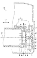
- the fuel pump unit 9 includes a suction filter 90 and a fuel pump 10 coupled to each other as shown in FIGS.
- the fuel pump unit 9 is disposed in the sub tank 2 of the fuel pump module 100 installed in the fuel tank for storing fuel in the vehicle.
- the fuel pump module 100 supplies fuel to the internal combustion engine by pumping the fuel in the fuel tank to the outside of the fuel tank.
- the fuel in the fuel tank flows into the sub tank 2 through the flapper valve.
- the fuel in the sub tank 2 is filtered by the suction filter 90 and then sucked into the fuel pump 10.
- the fuel discharged from the fuel pump 10 passes through a high-pressure filter and a pressure regulator, and is pumped out of the fuel tank through a flange that closes the fuel tank opening in the fuel pump module 100.
- the fuel in this embodiment is light oil.
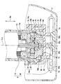
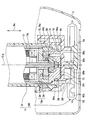
- the fuel pump 10 has an electric motor 13, a pump main body 19, and an electric motor 13 accommodated in an annular pump body 12 on the opposite side of the pump main body 19 across the axial direction Da.
- the protruding side cover 15 is mainly used.
- the rotating shaft 13a of the electric motor 13 is rotationally driven by energization from an external circuit via the electrical connector 15a of the side cover 15.
- the outer gear 30 and the inner gear 20 of the pump body 19 rotate using the driving force of the rotating shaft 13a.
- the fuel sucked into the gear housing chamber 70a in which both the gears 20 and 30 are housed and pressurized is discharged from the discharge outlet 15b of the side cover 15 through the fuel passage 16 outside the gear housing chamber 70a.
- an inner rotor type brushless motor is employed as the electric motor 13.
- the electric motor 13 has a stator 13b and a rotor 13c.
- the stator 13b is fixed to the pump body 12 and is formed in a cylindrical shape.
- the stator 13b has a winding portion molded of synthetic resin, and a 6-slot coil is formed and arranged.
- the rotor 13c is located on the inner peripheral side with respect to the stator 13b, and is formed in a cylindrical shape with a rotation shaft 13a assembled at the center.
- a quadrupole magnet is formed and arranged on the rotor 13c.
- the rotation shaft 13a is disposed along the rotation center line Cig set as a virtual straight line in the axial direction Da at the center of the pump.
- the axial direction Da substantially matches the direction of gravity when the vehicle travels on a flat ground or stops on a flat ground.
- the pump main body 19 includes a joint member 60, an inner gear 20, an outer gear 30, and a pump housing 70.
- the joint member 60 is formed of a synthetic resin such as PPS resin, for example, and is a member that relays the rotating shaft 13a with the inner gear 20.
- the joint member 60 integrally includes a main body portion 62 through which the rotary shaft 13a is inserted into the fitting hole 62a, and an insertion portion 64.
- a plurality of insertion portions 64 are provided at equal intervals in the circumferential direction.
- Each insertion portion 64 has flexibility due to the shape extending from the outer peripheral side portion of the main body portion 62 toward the gear housing chamber 70a along the axial direction.
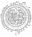
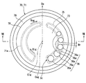
- the inner gear 20 shown in FIGS. 3 and 4 is a so-called trochoid gear which is formed of a rigid metal material such as an iron-based sintered body, for example, and each tooth has a trochoid curve.
- the inner gear 20 is arranged eccentrically in the gear housing chamber 70a by having the center together with the rotary shaft 13a.
- the inner gear 20 has an insertion hole 26 at a position facing the main body 62 of the joint member 60 in the axial direction Da.
- a plurality of insertion holes 26 are provided at equal intervals in the circumferential direction corresponding to each insertion portion 64. Each insertion hole 26 penetrates the inner gear 20 along the axial direction Da.
- each insertion hole 26 a corresponding insertion portion 64 is inserted with a gap.
- the insertion portion 64 presses against the insertion hole 26, whereby the driving force of the rotary shaft 13 a is transmitted to the inner gear 20 through the joint member 60. That is, the inner gear 20 is rotatable in the rotation direction Rig around the rotation center line Cig coaxial with the rotation shaft 13a.
- the inner gear 20 is rotatable in the rotation direction Rig around the rotation center line Cig coaxial with the rotation shaft 13a.
- FIG. 4 only a part of the insertion hole 26 and the insertion portion 64 are denoted by reference numerals.
- the inner gear 20 has a plurality of external teeth 24 a arranged at equal intervals in the rotation direction Rig on the outer peripheral portion 24.
- the outer gear 30 shown in FIGS. 3 and 4 is also a so-called trochoid gear that is formed of, for example, a metal material having rigidity of an iron-based sintered material, and each tooth has a trochoidal curve.
- the outer gear 30 is arranged coaxially in the gear accommodating chamber 70a by being eccentric with respect to the rotation center line Cig.
- the inner gear 20 is eccentric with respect to the outer gear 30 in an eccentric direction De as a radial direction of the outer gear 30.
- the outer gear 30 is eccentric from the rotation center line Cig and has a virtual outer center line Cog along the axial direction Da as the rotation center, so that the outer center line Cog is interlocked with the inner gear 20. It can be rotated in the surrounding rotation direction Rog.
- the outer gear 30 has a plurality of inner teeth 32 a arranged at equal intervals in the rotation direction Rog in the inner peripheral portion 32.
- the number of inner teeth 32 a in the outer gear 30 is set to be one more than the number of outer teeth 24 a in the inner gear 20. In the present embodiment, the number of inner teeth 32a is ten and the number of outer teeth 24a is nine.
- the inner gear 20 meshes with the outer gear 30 by relative eccentricity in the eccentric direction De.
- the gears 20 and 30 are engaged with each other with a small gap on the eccentric side, but a plurality of pump chambers 40 are formed between the gears 20 and 30 on the opposite side.
- the outer gear 30 and the inner gear 20 rotate according to the rotational drive of the rotating shaft 13a, so that the volume thereof is expanded and contracted.
- the outer gear 30 and the inner gear 20 constitute a rotor portion 19a that rotates in a gear housing chamber 70a as a rotor housing chamber.
- the pump housing 70 has a cylindrical hole-shaped gear housing chamber 70 a that rotatably accommodates both the gears 20 and 30 by superimposing the pump cover 71 and the pump casing 80 in the axial direction Da. It is defined. Accordingly, the pump housing 70 sandwiches both the gears 20 and 30 from both sides in the axial direction Da, thereby forming a pair of sliding surfaces 72 and 82 on which the both gears 20 and 30 slide in a planar shape. .
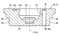
- the pump cover 71 shown in FIGS. 3 and 5 to 7 is a component of the pump housing 70.
- the pump cover 71 is formed in a disk shape having wear resistance by performing a surface treatment such as plating on a base material made of a metal having rigidity such as a steel material.
- a circular flat opening plane 73 projects outward.
- the pump cover 71 has an outer peripheral wall 78 connected to the outer edge of the opening plane 73 and facing the outer peripheral side. Due to the opening plane 73 and the outer peripheral wall 78, the suction filter 90 side of the pump cover 71 is formed in a cylindrical shape.
- a stopper that is connected to the outer peripheral wall 78 on the outer peripheral side of the outer peripheral wall 78 and closer to the gear housing chamber 70a and faces the suction filter 90 in the axial direction Da.
- a wall 79 is provided.
- the stopper wall 79 is provided in an annular shape so as to surround the outer peripheral wall 78 over the entire circumference.
- the pump cover 71 has a joint housing chamber 71b for housing the main body 62 of the joint member 60 at a location facing the inner gear 20 on the rotation center line Cig.
- the joint accommodation chamber 71b is recessed from the sliding surface 72 along the axial direction Da.
- a thrust bearing 52 is fitted and fixed to the bottom of the joint accommodation chamber 71b on the rotation center line Cig in order to support the rotation shaft 13a in the axial direction Da.
- the pump cover 71 has a suction port portion 74 for sucking fuel from the outside to the inside of the gear housing chamber 70a on the outer peripheral side of the joint housing chamber 71b.
- the suction port portion 74 has a suction extension groove 75 and a suction hole portion 76.
- the suction extending groove 75 is recessed from the sliding surface 72 and has an arcuate groove shape extending along the circumferential direction of the pump cover 71.
- the suction hole portion 76 has a plurality of suction opening holes 76a.
- the plurality of suction opening holes 76 a are provided, for example, and are arranged along the extending direction of the suction extending grooves 75.
- Each suction opening hole 76a is formed in a cylindrical hole shape penetrating the pump cover 71 along the axial direction Da so as to open at the bottom of the suction extending groove 75 and to the opening plane 73 on the suction filter 90 side. It is open.
- the suction hole 76 is disposed so as to be surrounded by the outer peripheral wall 78 provided over the entire circumference.
- Each suction opening hole 76a has an opening area corresponding to the volume of the opposing pump chamber 40, and the opening area of the suction opening hole 76a on the side opposite to the eccentric side is set to be the largest.
- a reinforcing rib 77 that reinforces the pump cover 71 is provided between the suction opening holes 76a.
- the width Wr of the reinforcing rib 77 is set substantially equal between the suction opening holes 76a.
- the pump casing 80 is formed in a bottomed cylindrical shape having wear resistance by performing a surface treatment such as plating on a base material made of a metal having rigidity such as a steel material.
- the opening of the pump casing 80 is covered with the pump cover 71 so as to be closed over the entire circumference.
- the inner peripheral portion 80b of the pump casing 80 is formed in a cylindrical hole shape that is eccentric from the rotation center line Cig and coaxial with the outer center line Cog.
- a radial bearing 50 is fitted and fixed on the rotation center line Cig of the concave bottom portion 80c of the pump casing 80 in order to support the rotating shaft 13a penetrating the concave bottom portion 80c.
- the pump casing 80 has a discharge port portion 84 that discharges fuel from the inside of the gear housing chamber 70 a to the outside on the outer peripheral side of the radial bearing 50.
- the discharge port portion 84 has a discharge extending groove 85 and a discharge hole portion 86.
- the discharge extending groove 85 is recessed from the sliding surface 82 and has an arcuate groove shape extending along the circumferential direction of the pump casing 80.
- the discharge hole portion 86 has a plurality of discharge opening holes 86a.
- the plurality of discharge opening holes 86 a are formed in a cylindrical hole shape penetrating the pump casing 80 along the axial direction Da, thereby opening at the bottom of the discharge extending groove 85 and opening at the fuel passage 16.
- a reinforcing rib 87 for reinforcing the pump casing 80 is provided between the discharge opening holes 86a.
- the discharge hole portion 86, the discharge opening hole 86 a, and a part of the reinforcing rib 87 are denoted by reference numerals.
- the suction extending groove 75 is formed in the portion facing the suction extending groove 75 of the suction port portion 74 with the gear housing chamber 70a interposed therebetween, as shown in FIG.
- an arcuate groove-shaped suction facing groove 80a is formed.
- the suction facing groove 80 a is formed to be recessed from the sliding surface 82.
- the discharge extending groove 85 of the discharge port portion 84 is provided with the outline of the suction opposing groove 80a substantially symmetrical with respect to the line.
- the discharge extending groove 85 and the suction facing groove 80a are separated by a sliding surface 82.
- a portion of the pump cover 71 that faces the discharge extending groove 85 of the discharge port portion 84 across the gear housing chamber 70a has an arc corresponding to the shape of the discharge extending groove 85 projected in the axial direction Da.
- a groove-like discharge facing groove 71a is formed.
- the discharge facing groove 71 a is formed to be recessed from the sliding surface 72.
- the suction extending groove 75 of the suction port portion 74 is provided with the discharge facing groove 71a and its contour substantially symmetrical with respect to the line.
- the sliding between the suction extending groove 75 and the discharge facing groove 71a is slid. It is separated by a surface 72.
- the inner gear 20 is formed so that its thickness dimension is slightly smaller than the dimension between the pair of sliding surfaces 72 and 82.
- the inner gear 20 has its inner peripheral portion 22 supported in the radial direction by the radial bearing 50 and is also supported by the pair of sliding surfaces 72 and 82 on both sides in the axial direction Da.
- the outer gear 30 has an outer diameter slightly smaller than the inner diameter of the pump casing 80. At the same time, the outer gear 30 is formed so that its thickness dimension is slightly smaller than the dimension between the pair of sliding surfaces 72 and 82. Thus, the outer gear 30 has its outer peripheral portion 34 supported by the inner peripheral portion 80b of the pump casing 80, and both sides in the axial direction Da are supported by the pair of sliding surfaces 72 and 82.
- each discharge opening 86 a of the discharge hole 86 communicates with the discharge extending groove 85 recessed from the sliding surface 82, so that the fuel discharge is performed while the pump chamber 40 faces the discharge extending groove 85. Will continue.
- the fuel filtered by the suction filter 90 is sucked from the suction port portion 74 of the fuel pump 10.
- the fuel sequentially sucked into the pump chamber 40 in the gear housing chamber 70a through the suction port portion 74 and then discharged through the discharge port portion 84 is discharged from the discharge outlet 15b to the outside of the fuel pump 10 through the fuel passage 16. .
- the suction filter 90 includes a filter element 92, a cylindrical hole portion 94, a contact portion 96, and an opposing wall 98.
- the filter element 92 has a bag shape in which an internal space 92a is formed.
- the filter element 92 is disposed with a gap in the axial direction Da from the sub tank bottom wall 2a, and has a shape extending along the bottom wall 2a.
- the filter element 92 filters foreign matters such as sand, dust, and gas station tank rust that may be contained in the fuel, and takes them into the internal space 92a. More specifically, light oil as a fuel has a higher viscosity than gasoline, and is particularly jelly-like in a low temperature state. Therefore, in order to suck such light oil, the filter element 92 has a coarser mesh than that of gasoline. Is also set roughly (for example, 100 to 200 ⁇ m).
- a frame portion 90a is disposed in the internal space 92a of the filter element 92.
- the shape of the bag-like filter element 92 is maintained by the skeleton 90a. If such a filter element 92 is inclined, for example, when the amount of fuel in the sub-tank 2 decreases, the area where the filter element 92 contacts the fuel decreases, and the intake amount may decrease. is there. Alternatively, when the filter element 92 contacts the sub tank bottom wall 2a, noise due to vibration may occur.
- the cylindrical hole portion 94, the contact portion 96, and the opposing wall 98 are integrally formed of, for example, a rigid resin such as polyphenylene sulfide (PPS) resin or polyacetal (POM) resin.
- a coupling member 99 is configured.
- the cylindrical hole portion 94 is formed in a cylindrical hole shape having an inner peripheral wall 94a.
- the cylindrical hole portion 94 has one end communicating with the internal space 92 a of the filter element 92.
- the other end on the fuel pump 10 side can be fitted with the fuel pump 10 by opening as an opening 94b.
- the contact portion 96 is formed in an annular shape connected to the outer peripheral side from the opening portion 94b of the cylindrical hole portion 94, and constitutes the cylindrical end portion of the coupling member 99 by facing the fuel pump 10 side in the axial direction Da. . That is, the contact portion 96 is provided on the outer peripheral side with respect to the inner peripheral wall 94a.
- the suction filter 90 is coupled to the fuel pump 10 by press-fitting the coupling member 99 into the pump cover 71 along the axial direction Da.
- the cylindrical hole portion 94 is fitted with the inner peripheral wall 94a thereof opposed to the outer peripheral wall 78 of the fuel pump 10 in the radial direction.
- the outer peripheral wall 78 and the inner peripheral wall 94a are in a press-contact state over the entire circumference by being fitted by press fitting.
- the contact portion 96 is in contact with the stopper wall 79 of the fuel pump 10 and the axial direction Da over the entire circumference, the displacement of the suction filter 90 with respect to the fuel pump 10 is regulated. .
- the cylindrical hole portion 94 communicates the internal space 92 a of the filter element 92 and the suction opening holes 76 a of the suction hole portion 76 together.
- the cylindrical hole portion 94 is disposed so that the rotation center line Cig passes through the inner peripheral wall 94a.
- the cylindrical hole portion 94 is disposed on the same axis as the rotation shaft 13 a because the rotation center line Cig and the center of the cylindrical hole portion 94 substantially coincide with each other.
- the outer center line Cog that is eccentric from the rotation center line Cig also passes through the inner peripheral wall 94a.
- the inner peripheral wall 94a is provided on the outer peripheral side with respect to the inner gear 20 connected to the rotary shaft 13a and the rotor 13c of the electric motor 13.
- the opposing wall 98 is formed so as to protrude from the inner peripheral wall 94a to the inner peripheral side on the filter element 92 side of the opening plane 73 disposed inside the cylindrical hole portion 94 and surrounded by the inner peripheral wall 94a.
- the facing wall 98 faces the opening plane 73 with a gap in the axial direction Da.
- a connecting portion 90b that protrudes from the location on the rotation center line Cig of the opposing wall 98 toward the filter element 92 and is connected to the frame portion 90a is provided. Further, the opposing wall 98 does not completely block the cylindrical hole portion 94, and a hollow cavity portion 90c is provided in the cylindrical hole portion 94 where the suction hole portion 76 is extended in the axial direction Da.
- the cylindrical hole portion 94 formed with the inner peripheral wall 94a in a cylindrical hole shape is fitted with the outer peripheral wall 78 provided surrounding the suction hole 76 in the fuel pump 10 and the inner peripheral wall 94a facing each other.
- the internal space 92a of the filter element 92 and the suction hole 76 are communicated.
- the cylindrical hole part 94 is arrange
- the contact portion 96 is in contact with the fuel pump 10 in the axial direction Da.
- the contact portion 96 can receive a force that cancels the inclination from the fuel pump 10. Therefore, the inclination of the suction filter 90 can be suppressed.
- the contact portion 96 is formed in an annular shape connected to the outer peripheral side from the opening portion 94b of the cylindrical hole portion 94. Therefore, the contact portion 96 and the fuel pump 10 are annularly contacted in the axial direction Da on the outer peripheral side of the inner peripheral wall 94a surrounding the rotation center line Cig. Under such circumstances, even if the suction filter 90 tends to tilt in an arbitrary direction due to transmission of vibrations that can occur in the fuel pump 10, the contact portion 96 can reliably receive a force that cancels the tilt. Therefore, the inclination of the suction filter 90 can be suppressed.
- the cylindrical hole portion 94 is formed in a cylindrical hole shape coaxial with the rotating shaft 13a.
- the cylindrical hole part 94 and the rotating shaft 13a are arrange
- the suction hole 76 opens in the flat opening plane 73. Therefore, when the fuel is sucked into the suction hole 76 from the internal space 92a of the filter element 92 through the cylindrical hole 94, the fuel flow is less likely to be disturbed, and the fuel pressure fluctuation, pulsation, or vibration is suppressed. it can.
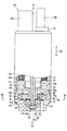
- the second embodiment of the present disclosure is a modification of the first embodiment.
- the second embodiment will be described with a focus on differences from the first embodiment.
- the fuel pump 10 in the second embodiment includes an opening plane 73 in which the suction hole 76 opens.
- the suction filter 290 in the second embodiment includes an opposing wall 98 facing the opening plane 73 and the axial direction Da, as in the first embodiment.
- the suction filter 290 further includes an elastic member 291.
- the elastic member 291 is, for example, a rubber packing mainly composed of synthetic rubber formed in a thin partial circle, and is formed to be elastically deformable.
- the elastic member 291 is disposed between the opening plane 73 and the facing wall 98 and can exert an elastic force on the opening plane 73 and the facing wall 98.
- the fuel pump 10 and the suction filter 290 are in contact with each other in the axial direction Da via the elastic member 291.
- the elastic member 291 is disposed between the opening plane 73 and the opposing wall 98. Since such an elastic member 291 absorbs vibration that can be generated in the fuel pump 10 due to elastic deformation, the inclination of the suction filter 290 can be suppressed.
- the suction filter 90 may include an elastic member on the inner peripheral wall 94a.
- an annular rubber packing as an elastic member 991 is embedded in a part of the inner peripheral wall 94a.
- the contact portion 96 may not be formed in an annular shape connected to the outer peripheral side from the opening portion 94b of the cylindrical hole portion 94.
- the opposing wall 98 may correspond to the contact portion 96 by contacting the opening plane 73 of the fuel pump 10 in the axial direction Da.
- a snap-fit claw may be provided on the suction filter 90 so that the claw contacts the fuel pump 10 in the axial direction Da.
- the cylindrical hole portion 94 may be slightly decentered with respect to the rotation center line Cig as long as the rotation center line Cig is disposed so as to pass inside the inner peripheral wall 94a.
- the cylindrical hole portion 94 may have a cylindrical hole shape other than the cylindrical hole shape, such as an ellipse or a polygon.
- the suction hole 76 may be open to a curved surface other than the flat opening plane 73.
- the suction hole 76 may be constituted by a single suction opening hole 76a.
- the outer peripheral wall 78 may be configured to surround a single suction opening hole 76 a as the suction hole portion 76.
- gasoline other than light oil or liquid fuel based on these may be employed.
Abstract
A fuel pump unit (9) is provided with: a suction filter (19); and a fuel pump (10) that suctions fuel filtered through the suction filter (90). The fuel pump (10) is provided with: a rotary shaft (13a) placed along a rotational center line (Cig) and driven to rotate; a rotor part (19a) rotated according to the rotary-driving of the rotary shaft (13a); a suction hole part (76) that suctions the fuel into a rotor storage chamber; and an outer circumferential wall (78) provided to surround the suction hole part (76). The suction filter (90) is provided with: a filter element (92) that filters the fuel to capture the fuel in an internal space (92a); and a cylindrical hole part (94) that is formed into a cylindrical hole shape having an inner circumferential wall (94a), and communicatively connects the internal space (92a) and the suction hole part (76) with each other by fitting the outer circumferential wall (78) and the inner circumferential wall (94a) so as to face each other. The cylindrical hole part (94) is arranged in a manner that the rotational center line (Cig) passes through the inside of the inner circumferential wall (94a).
Description
本願は、2015年12月17日に出願された日本国特許出願第2015-246453号に基づくものであり、この開示をもってその内容を本明細書中に開示したものとする。
This application is based on Japanese Patent Application No. 2015-246453 filed on Dec. 17, 2015, and the contents thereof are disclosed in this specification.
本開示は、サクションフィルタと、燃料ポンプと、を具備する燃料ポンプユニットに関する。
The present disclosure relates to a fuel pump unit including a suction filter and a fuel pump.
従来、サクションフィルタと、燃料ポンプと、を具備する燃料ポンプユニットが知られている。特許文献1に開示の燃料ポンプユニットにおいて燃料ポンプは、サクションフィルタにより濾過された燃料を吸入するようになっている。燃料ポンプは、ロータ収容室内に燃料を吸入する吸入穴部及び当該吸入穴部を囲んで設けられる外周壁を備えている。
Conventionally, a fuel pump unit including a suction filter and a fuel pump is known. In the fuel pump unit disclosed in Patent Document 1, the fuel pump sucks the fuel filtered by the suction filter. The fuel pump includes a suction hole portion for sucking fuel into the rotor housing chamber and an outer peripheral wall provided to surround the suction hole portion.
これに対してサクションフィルタは、フィルタエレメント及び筒穴部を有している。フィルタエレメントは、燃料を濾過して内部空間に取り込む。筒穴部は、内周壁を有する筒穴状に形成され、外周壁と内周壁とを相対させて嵌合されていることで、内部空間と吸入穴部とを連通している。
In contrast, the suction filter has a filter element and a cylindrical hole. The filter element filters the fuel and takes it into the internal space. The cylindrical hole portion is formed in a cylindrical hole shape having an inner peripheral wall, and the inner space and the suction hole portion are communicated with each other by being fitted with the outer peripheral wall and the inner peripheral wall facing each other.
ここで、当該燃料ポンプの中心軸がロータ部を回転させる回転軸の回転中心線と同等のものであると仮定すると、特許文献1の筒穴部は、当該回転中心線が内周壁の外側を通るように配置されていることとなる。しかしながら、このような構成では、回転軸の回転駆動に伴って燃料ポンプにて発生し得る振動が筒穴部のうち特定箇所に伝達し易くなる等、振動の伝達が均一でなかった。不均一な振動の伝達により、燃料ポンプに対してサクションフィルタが傾いてしまうことが懸念されている。
Here, if it is assumed that the center axis of the fuel pump is equivalent to the rotation center line of the rotating shaft that rotates the rotor portion, the cylindrical hole portion of Patent Document 1 has the rotation center line outside the inner peripheral wall. It will be arranged to pass. However, in such a configuration, the vibration transmission is not uniform, such as the vibration that can be generated in the fuel pump with the rotation of the rotating shaft is easily transmitted to a specific portion of the cylindrical hole portion. There is a concern that the suction filter may be inclined with respect to the fuel pump due to non-uniform vibration transmission.
本開示は、以上説明した問題に鑑みてなされたものであって、その目的は、サクションフィルタの傾きを抑制する燃料ポンプユニットを提供することにある。
The present disclosure has been made in view of the problems described above, and an object thereof is to provide a fuel pump unit that suppresses the inclination of the suction filter.
本開示では、燃料を濾過するサクションフィルタと、サクションフィルタにより濾過された燃料を吸入する燃料ポンプと、を具備する燃料ポンプユニットであって、
燃料ポンプは、
回転中心線に沿って配置され、回転駆動される回転軸と、
ロータ収容室に収容され、回転軸の回転駆動に応じて回転するロータ部と、
ロータ収容室内に燃料を吸入する吸入穴部と、
吸入穴部を囲んで設けられる外周壁と、を備え、
サクションフィルタは、
燃料を濾過して内部空間に取り込むフィルタエレメントと、
内周壁を有する筒穴状に形成され、外周壁と内周壁を相対させて嵌合されていることで、内部空間と吸入穴部とを連通する筒穴部と、を備え、
筒穴部は、回転中心線が内周壁の内側を通るように配置される燃料ポンプユニットを提供する。 In the present disclosure, a fuel pump unit comprising a suction filter that filters fuel and a fuel pump that sucks fuel filtered by the suction filter,
The fuel pump
A rotation axis disposed along the rotation center line and driven to rotate;
A rotor portion housed in the rotor housing chamber and rotated according to the rotational drive of the rotation shaft;
A suction hole for sucking fuel into the rotor accommodating chamber;
An outer peripheral wall provided surrounding the suction hole,
Suction filter
A filter element that filters fuel into the internal space;
It is formed in a cylindrical hole shape having an inner peripheral wall, and is fitted with the outer peripheral wall and the inner peripheral wall facing each other, thereby providing a cylindrical hole portion that communicates the internal space and the suction hole portion,
The cylindrical hole portion provides a fuel pump unit that is arranged so that the rotation center line passes through the inside of the inner peripheral wall.
このような構成によると、内周壁を筒穴状に形成される筒穴部は、燃料ポンプにおいて吸入穴部を囲んで設けられる外周壁と当該内周壁を相対させて嵌合されていることで、フィルタエレメントの内部空間と、吸入穴部とを連通している。そして、筒穴部は、回転中心線が内周壁の内側を通るように配置されている。このようにすることで、回転軸の回転駆動に伴って燃料ポンプにて発生し得る振動が、筒穴部の特定箇所に伝達し易くなることを抑制できる。すなわち、振動の伝達における周方向の均一性を高めることにより、燃料ポンプに対するサクションフィルタの傾きを抑制することができる。
According to such a configuration, the cylindrical hole portion formed in the cylindrical hole shape on the inner peripheral wall is fitted with the outer peripheral wall provided surrounding the suction hole portion in the fuel pump and the inner peripheral wall being opposed to each other. The internal space of the filter element communicates with the suction hole. And the cylinder hole part is arrange | positioned so that a rotation center line may pass the inner side of an inner peripheral wall. By doing in this way, it can suppress that the vibration which can generate | occur | produce with a fuel pump with the rotational drive of a rotating shaft becomes easy to transmit to the specific location of a cylinder hole part. That is, the inclination of the suction filter with respect to the fuel pump can be suppressed by increasing the uniformity in the circumferential direction in vibration transmission.
以下、本開示の複数の実施形態を図面に基づいて説明する。なお、各実施形態において対応する構成要素には同一の符号を付すことにより、重複する説明を省略する場合がある。各実施形態において構成の一部分のみを説明している場合、当該構成の他の部分については、先行して説明した他の実施形態の構成を適用することができる。また、各実施形態の説明において明示している構成の組み合わせばかりではなく、特に組み合わせに支障が生じなければ、明示していなくても複数の実施形態の構成同士を部分的に組み合せることができる。
Hereinafter, a plurality of embodiments of the present disclosure will be described with reference to the drawings. In addition, the overlapping description may be abbreviate | omitted by attaching | subjecting the same code | symbol to the corresponding component in each embodiment. When only a part of the configuration is described in each embodiment, the configuration of the other embodiment described above can be applied to the other part of the configuration. In addition, not only combinations of configurations explicitly described in the description of each embodiment, but also the configurations of a plurality of embodiments can be partially combined even if they are not explicitly specified unless there is a problem with the combination. .
(第1実施形態)
本開示の第1実施形態による燃料ポンプユニット9は、図1,2に示すように、互いに結合されたサクションフィルタ90及び燃料ポンプ10を具備している。燃料ポンプユニット9は、車両において、燃料を貯留する燃料タンク内に設置された燃料ポンプモジュール100のサブタンク2内に配置されている。 (First embodiment)
Thefuel pump unit 9 according to the first embodiment of the present disclosure includes a suction filter 90 and a fuel pump 10 coupled to each other as shown in FIGS. The fuel pump unit 9 is disposed in the sub tank 2 of the fuel pump module 100 installed in the fuel tank for storing fuel in the vehicle.
本開示の第1実施形態による燃料ポンプユニット9は、図1,2に示すように、互いに結合されたサクションフィルタ90及び燃料ポンプ10を具備している。燃料ポンプユニット9は、車両において、燃料を貯留する燃料タンク内に設置された燃料ポンプモジュール100のサブタンク2内に配置されている。 (First embodiment)
The
燃料ポンプモジュール100は、燃料タンク内の燃料を燃料タンク外に圧送することで、内燃機関へ供給する。詳細は図示しないが、燃料タンク内の燃料がフラッパバルブを通じてサブタンク2内に流入する。そしてサブタンク2内の燃料がサクションフィルタ90に濾過された後、燃料ポンプ10内に吸入される。その後、燃料ポンプ10から吐出された燃料は、高圧フィルタ及びプレッシャレギュレータを経て、燃料ポンプモジュール100において燃料タンク開口部を塞ぐフランジを通じて燃料タンク外に圧送されるのである。ここで、本実施形態における燃料は軽油となっている。
The fuel pump module 100 supplies fuel to the internal combustion engine by pumping the fuel in the fuel tank to the outside of the fuel tank. Although not shown in detail, the fuel in the fuel tank flows into the sub tank 2 through the flapper valve. Then, the fuel in the sub tank 2 is filtered by the suction filter 90 and then sucked into the fuel pump 10. Thereafter, the fuel discharged from the fuel pump 10 passes through a high-pressure filter and a pressure regulator, and is pumped out of the fuel tank through a flange that closes the fuel tank opening in the fuel pump module 100. Here, the fuel in this embodiment is light oil.
燃料ポンプ10は、図3に示すように、円環状のポンプボディ12内部に収容された電動モータ13、ポンプ本体19、及び電動モータ13を軸方向Daに挟んでポンプ本体19とは反対側に張り出したサイドカバー15を主体として構成されている。
As shown in FIG. 3, the fuel pump 10 has an electric motor 13, a pump main body 19, and an electric motor 13 accommodated in an annular pump body 12 on the opposite side of the pump main body 19 across the axial direction Da. The protruding side cover 15 is mainly used.
こうした燃料ポンプ10では、サイドカバー15の電気コネクタ15aを介した外部回路からの通電により、電動モータ13の回転軸13aが回転駆動される。回転軸13aの駆動力を利用して、ポンプ本体19のアウタギヤ30及びインナギヤ20が回転する。これにより、両ギヤ20,30が収容されているギヤ収容室70aに吸入されて加圧された燃料は、ギヤ収容室70a外の燃料通路16を通じて、サイドカバー15の吐出出口15bから吐出される。
In such a fuel pump 10, the rotating shaft 13a of the electric motor 13 is rotationally driven by energization from an external circuit via the electrical connector 15a of the side cover 15. The outer gear 30 and the inner gear 20 of the pump body 19 rotate using the driving force of the rotating shaft 13a. Thereby, the fuel sucked into the gear housing chamber 70a in which both the gears 20 and 30 are housed and pressurized is discharged from the discharge outlet 15b of the side cover 15 through the fuel passage 16 outside the gear housing chamber 70a. .
本実施形態では、電動モータ13として、インナロータ型のブラシレスモータが採用されている。電動モータ13は、固定子13b及び回転子13cを有している。固定子13bは、ポンプボディ12に対して固定され、円筒状に形成されている。固定子13bには、合成樹脂によりモールドされた巻線部があり、6スロットのコイルが形成配置されている。回転子13cは、固定子13bよりも内周側に位置し、中央に回転軸13aを組み付けた円筒状に形成されている。回転子13cには、4極のマグネットが形成配置されている。こうして、回転子13c及び回転軸13aは共に回転する。回転軸13aは、ポンプ中心部に軸方向Daに仮想の直線として設定された回転中心線Cigに沿って配置されている。なお、本実施形態において軸方向Daは、車両が平地を走行するとき又は平地に停車するときの重力方向に実質一致している。
In this embodiment, an inner rotor type brushless motor is employed as the electric motor 13. The electric motor 13 has a stator 13b and a rotor 13c. The stator 13b is fixed to the pump body 12 and is formed in a cylindrical shape. The stator 13b has a winding portion molded of synthetic resin, and a 6-slot coil is formed and arranged. The rotor 13c is located on the inner peripheral side with respect to the stator 13b, and is formed in a cylindrical shape with a rotation shaft 13a assembled at the center. A quadrupole magnet is formed and arranged on the rotor 13c. Thus, both the rotor 13c and the rotating shaft 13a rotate. The rotation shaft 13a is disposed along the rotation center line Cig set as a virtual straight line in the axial direction Da at the center of the pump. In this embodiment, the axial direction Da substantially matches the direction of gravity when the vehicle travels on a flat ground or stops on a flat ground.
ポンプ本体19は、ジョイント部材60、インナギヤ20、アウタギヤ30、及びポンプハウジング70を備えている。
The pump main body 19 includes a joint member 60, an inner gear 20, an outer gear 30, and a pump housing 70.
ジョイント部材60は、例えばPPS樹脂等の合成樹脂により形成され、回転軸13aをインナギヤ20と中継する部材である。ジョイント部材60は、回転軸13aが嵌合穴62aに挿通される本体部62、及び挿入部64を一体的に有している。挿入部64は、周方向に等間隔に複数設けられている。各挿入部64は、本体部62の外周側箇所から軸方向に沿ってギヤ収容室70a側に延伸している形状により、可撓性を有している。
The joint member 60 is formed of a synthetic resin such as PPS resin, for example, and is a member that relays the rotating shaft 13a with the inner gear 20. The joint member 60 integrally includes a main body portion 62 through which the rotary shaft 13a is inserted into the fitting hole 62a, and an insertion portion 64. A plurality of insertion portions 64 are provided at equal intervals in the circumferential direction. Each insertion portion 64 has flexibility due to the shape extending from the outer peripheral side portion of the main body portion 62 toward the gear housing chamber 70a along the axial direction.
図3,4に示すインナギヤ20は、例えば鉄系焼結体等の剛性を有する金属材料により形成され、それぞれの歯をトロコイド曲線とした、所謂トロコイドギヤとなっている。インナギヤ20は、中心を回転軸13aと共にすることで、ギヤ収容室70a内では偏心して配置されている。
The inner gear 20 shown in FIGS. 3 and 4 is a so-called trochoid gear which is formed of a rigid metal material such as an iron-based sintered body, for example, and each tooth has a trochoid curve. The inner gear 20 is arranged eccentrically in the gear housing chamber 70a by having the center together with the rotary shaft 13a.
インナギヤ20は、ジョイント部材60の本体部62と軸方向Daに対向する箇所において、挿入穴26を有している。挿入穴26は、各挿入部64に対応して、周方向に等間隔に複数設けられている。各挿入穴26は、軸方向Daに沿ってインナギヤ20を貫通している。
The inner gear 20 has an insertion hole 26 at a position facing the main body 62 of the joint member 60 in the axial direction Da. A plurality of insertion holes 26 are provided at equal intervals in the circumferential direction corresponding to each insertion portion 64. Each insertion hole 26 penetrates the inner gear 20 along the axial direction Da.
各挿入穴26には、それぞれ対応する挿入部64が隙間をあけて挿入されている。回転軸13aが回転駆動されると、挿入部64が挿入穴26に押し当たることで、当該回転軸13aの駆動力がジョイント部材60を介してインナギヤ20に伝達される。すなわち、インナギヤ20は、回転軸13aと同軸上の回転中心線Cig周りとなる回転方向Rigへ回転可能となっている。なお、図4では、挿入穴26及び挿入部64の一部にのみ符号が付されている。
In each insertion hole 26, a corresponding insertion portion 64 is inserted with a gap. When the rotary shaft 13 a is driven to rotate, the insertion portion 64 presses against the insertion hole 26, whereby the driving force of the rotary shaft 13 a is transmitted to the inner gear 20 through the joint member 60. That is, the inner gear 20 is rotatable in the rotation direction Rig around the rotation center line Cig coaxial with the rotation shaft 13a. In FIG. 4, only a part of the insertion hole 26 and the insertion portion 64 are denoted by reference numerals.
また、インナギヤ20は、図4に示すように、回転方向Rigに等間隔に並ぶ複数の外歯24aを、外周部24に有している。
Further, as shown in FIG. 4, the inner gear 20 has a plurality of external teeth 24 a arranged at equal intervals in the rotation direction Rig on the outer peripheral portion 24.
図3,4に示すアウタギヤ30も、例えば鉄系焼結材の剛性を有する金属材料により形成され、それぞれの歯をトロコイド曲線とした、所謂トロコイドギヤとなっている。アウタギヤ30は、回転中心線Cigに対して偏心することで、ギヤ収容室70aでは同軸上に配置されている。これによりアウタギヤ30に対しては、当該アウタギヤ30の一径方向としての偏心方向Deにインナギヤ20が偏心している。
The outer gear 30 shown in FIGS. 3 and 4 is also a so-called trochoid gear that is formed of, for example, a metal material having rigidity of an iron-based sintered material, and each tooth has a trochoidal curve. The outer gear 30 is arranged coaxially in the gear accommodating chamber 70a by being eccentric with respect to the rotation center line Cig. As a result, the inner gear 20 is eccentric with respect to the outer gear 30 in an eccentric direction De as a radial direction of the outer gear 30.
アウタギヤ30は、図4に示すように、回転中心線Cigから偏心し、軸方向Daに沿った仮想のアウタ中心線Cogを回転中心とすることで、インナギヤ20と連動して当該アウタ中心線Cog周りとなる回転方向Rogへ回転可能となっている。アウタギヤ30は、そうした回転方向Rogに等間隔に並ぶ複数の内歯32aを内周部32に有している。ここでアウタギヤ30における内歯32aの数は、インナギヤ20における外歯24aの数よりも1つ多くなるように設定されている。本実施形態では、内歯32aの数は10つ、外歯24aの数は9つとなっている。
As shown in FIG. 4, the outer gear 30 is eccentric from the rotation center line Cig and has a virtual outer center line Cog along the axial direction Da as the rotation center, so that the outer center line Cog is interlocked with the inner gear 20. It can be rotated in the surrounding rotation direction Rog. The outer gear 30 has a plurality of inner teeth 32 a arranged at equal intervals in the rotation direction Rog in the inner peripheral portion 32. Here, the number of inner teeth 32 a in the outer gear 30 is set to be one more than the number of outer teeth 24 a in the inner gear 20. In the present embodiment, the number of inner teeth 32a is ten and the number of outer teeth 24a is nine.
アウタギヤ30に対してインナギヤ20は、偏心方向Deへの相対的な偏心により噛合している。これにより、偏心側では、両ギヤ20,30は隙間少なく噛合しているが、その反対側では、両ギヤ20,30の間には、ポンプ室40が複数連なって形成されている。このようなポンプ室40では、アウタギヤ30及びインナギヤ20が回転軸13aの回転駆動に応じて回転することにより、その容積が拡縮するようになっている。こうしてアウタギヤ30及びインナギヤ20は、ロータ収容室としてのギヤ収容室70aにて回転するロータ部19aを構成している。
The inner gear 20 meshes with the outer gear 30 by relative eccentricity in the eccentric direction De. As a result, the gears 20 and 30 are engaged with each other with a small gap on the eccentric side, but a plurality of pump chambers 40 are formed between the gears 20 and 30 on the opposite side. In such a pump chamber 40, the outer gear 30 and the inner gear 20 rotate according to the rotational drive of the rotating shaft 13a, so that the volume thereof is expanded and contracted. Thus, the outer gear 30 and the inner gear 20 constitute a rotor portion 19a that rotates in a gear housing chamber 70a as a rotor housing chamber.
ポンプハウジング70は、図3に示すように、ポンプカバー71とポンプケーシング80とを軸方向Daに重ね合わせることで、両ギヤ20,30を回転可能に収容する円筒穴状のギヤ収容室70aを画成している。これにより、ポンプハウジング70は、両ギヤ20,30を軸方向Daの両側から挟むことで、それら両ギヤ20,30が摺動する一対の摺動面72,82を平面状に形成している。
As shown in FIG. 3, the pump housing 70 has a cylindrical hole-shaped gear housing chamber 70 a that rotatably accommodates both the gears 20 and 30 by superimposing the pump cover 71 and the pump casing 80 in the axial direction Da. It is defined. Accordingly, the pump housing 70 sandwiches both the gears 20 and 30 from both sides in the axial direction Da, thereby forming a pair of sliding surfaces 72 and 82 on which the both gears 20 and 30 slide in a planar shape. .
図3,5~7に示すポンプカバー71は、ポンプハウジング70の一構成部品である。ポンプカバー71は、鉄鋼材等の剛性を有する金属からなる基材に、めっき等の表面処理を施すことで、耐摩耗性を有する円盤状に形成されている。
The pump cover 71 shown in FIGS. 3 and 5 to 7 is a component of the pump housing 70. The pump cover 71 is formed in a disk shape having wear resistance by performing a surface treatment such as plating on a base material made of a metal having rigidity such as a steel material.
ポンプカバー71において、電動モータ13を軸方向Daに挟んで反対側のサクションフィルタ90側では、円形平面状の開口平面73が外部に張り出している。またポンプカバー71は、開口平面73の外縁部に接続されて外周側を向く外周壁78を有している。開口平面73及び外周壁78により、ポンプカバー71のサクションフィルタ90側は、円柱状に形成されている。
In the pump cover 71, on the side of the suction filter 90 on the opposite side across the electric motor 13 in the axial direction Da, a circular flat opening plane 73 projects outward. The pump cover 71 has an outer peripheral wall 78 connected to the outer edge of the opening plane 73 and facing the outer peripheral side. Due to the opening plane 73 and the outer peripheral wall 78, the suction filter 90 side of the pump cover 71 is formed in a cylindrical shape.
また外周壁78の開口平面73とは反対側には、当該外周壁78よりも外周側かつギヤ収容室70a側において、当該外周壁78と接続されて軸方向Daのサクションフィルタ90側を向くストッパ壁79が設けられている。ストッパ壁79は、外周壁78を全周に亘って囲むように、環状に設けられている。
Further, on the opposite side of the outer peripheral wall 78 from the opening plane 73, a stopper that is connected to the outer peripheral wall 78 on the outer peripheral side of the outer peripheral wall 78 and closer to the gear housing chamber 70a and faces the suction filter 90 in the axial direction Da. A wall 79 is provided. The stopper wall 79 is provided in an annular shape so as to surround the outer peripheral wall 78 over the entire circumference.
一方、燃料ポンプ10の内部においてポンプカバー71は、ジョイント部材60の本体部62を収容するジョイント収容室71bを、回転中心線Cig上の、インナギヤ20と対向する箇所において有している。ジョイント収容室71bは、摺動面72から軸方向Daに沿って凹んでいる。回転中心線Cig上のジョイント収容室71b底部には、回転軸13aを軸方向Daに軸受するために、スラスト軸受52が嵌合固定されている。
On the other hand, inside the fuel pump 10, the pump cover 71 has a joint housing chamber 71b for housing the main body 62 of the joint member 60 at a location facing the inner gear 20 on the rotation center line Cig. The joint accommodation chamber 71b is recessed from the sliding surface 72 along the axial direction Da. A thrust bearing 52 is fitted and fixed to the bottom of the joint accommodation chamber 71b on the rotation center line Cig in order to support the rotation shaft 13a in the axial direction Da.
ジョイント収容室71bよりも外周側において、ポンプカバー71は、ギヤ収容室70aの外部から内部へと、燃料を吸入する吸入ポート部74を有している。吸入ポート部74は、吸入延伸溝75及び吸入穴部76を有している。吸入延伸溝75は、摺動面72から凹み、ポンプカバー71の周方向に沿って延伸する円弧溝状を呈している。吸入穴部76は、複数の吸入開口穴76aを有している。複数の吸入開口穴76aは、例えば5つ設けられ、互いに吸入延伸溝75の延伸方向に沿って配列されている。各吸入開口穴76aは、軸方向Daに沿ってポンプカバー71を貫通する円筒穴状に形成されていることで、吸入延伸溝75の底部に開口すると共に、サクションフィルタ90側の開口平面73に開口している。こうして吸入穴部76は、全周に亘って設けられた外周壁78に囲まれた配置となっている。
The pump cover 71 has a suction port portion 74 for sucking fuel from the outside to the inside of the gear housing chamber 70a on the outer peripheral side of the joint housing chamber 71b. The suction port portion 74 has a suction extension groove 75 and a suction hole portion 76. The suction extending groove 75 is recessed from the sliding surface 72 and has an arcuate groove shape extending along the circumferential direction of the pump cover 71. The suction hole portion 76 has a plurality of suction opening holes 76a. The plurality of suction opening holes 76 a are provided, for example, and are arranged along the extending direction of the suction extending grooves 75. Each suction opening hole 76a is formed in a cylindrical hole shape penetrating the pump cover 71 along the axial direction Da so as to open at the bottom of the suction extending groove 75 and to the opening plane 73 on the suction filter 90 side. It is open. Thus, the suction hole 76 is disposed so as to be surrounded by the outer peripheral wall 78 provided over the entire circumference.
各吸入開口穴76aは、対向するポンプ室40の容積に合わせた開口面積となっており、偏心側とは最も反対側の吸入開口穴76aの開口面積が、最も大きく設定されている。各吸入開口穴76aの間には、ポンプカバー71を補強する補強リブ77が設けられている。各吸入開口穴76a間において補強リブ77の幅Wrは、実質等しく設定されている。
Each suction opening hole 76a has an opening area corresponding to the volume of the opposing pump chamber 40, and the opening area of the suction opening hole 76a on the side opposite to the eccentric side is set to be the largest. A reinforcing rib 77 that reinforces the pump cover 71 is provided between the suction opening holes 76a. The width Wr of the reinforcing rib 77 is set substantially equal between the suction opening holes 76a.
図3,4に示すポンプケーシング80は、ポンプハウジング70の一構成部品である。ポンプケーシング80は、鉄鋼材等の剛性を有する金属からなる基材に、めっき等の表面処理を施すことで、耐摩耗性を有する有底円筒状に形成されている。ポンプケーシング80のうち開口部は、ポンプカバー71により覆われることで、全周に亘って閉じられている。ポンプケーシング80の内周部80bは、回転中心線Cigから偏心し、かつ、アウタ中心線Cogと同軸上の円筒穴状に形成されている。
3 and 4 is a component part of the pump housing 70. The pump casing 80 is formed in a bottomed cylindrical shape having wear resistance by performing a surface treatment such as plating on a base material made of a metal having rigidity such as a steel material. The opening of the pump casing 80 is covered with the pump cover 71 so as to be closed over the entire circumference. The inner peripheral portion 80b of the pump casing 80 is formed in a cylindrical hole shape that is eccentric from the rotation center line Cig and coaxial with the outer center line Cog.
ポンプケーシング80の凹底部80cのうち回転中心線Cig上には、当該凹底部80cを貫通する回転軸13aを軸受するためにラジアル軸受50が嵌合固定されている。
A radial bearing 50 is fitted and fixed on the rotation center line Cig of the concave bottom portion 80c of the pump casing 80 in order to support the rotating shaft 13a penetrating the concave bottom portion 80c.
ポンプケーシング80は、ラジアル軸受50よりも外周側に、ギヤ収容室70aの内部から外部へ燃料を吐出する吐出ポート部84を有している。吐出ポート部84は、吐出延伸溝85及び吐出穴部86を有している。吐出延伸溝85は、摺動面82から凹み、ポンプケーシング80の周方向に沿って延伸する円弧溝状を呈している。吐出穴部86は、複数の吐出開口穴86aを有している。複数の吐出開口穴86aは、軸方向Daに沿ってポンプケーシング80を貫通する円筒穴状に形成されることで、吐出延伸溝85の底部に開口すると共に、燃料通路16に開口している。各吐出開口穴86aの間には、ポンプケーシング80を補強する補強リブ87が設けられている。なお、図4では、吐出穴部86、吐出開口穴86a、及び補強リブ87の一部にのみ符号が付されている。
The pump casing 80 has a discharge port portion 84 that discharges fuel from the inside of the gear housing chamber 70 a to the outside on the outer peripheral side of the radial bearing 50. The discharge port portion 84 has a discharge extending groove 85 and a discharge hole portion 86. The discharge extending groove 85 is recessed from the sliding surface 82 and has an arcuate groove shape extending along the circumferential direction of the pump casing 80. The discharge hole portion 86 has a plurality of discharge opening holes 86a. The plurality of discharge opening holes 86 a are formed in a cylindrical hole shape penetrating the pump casing 80 along the axial direction Da, thereby opening at the bottom of the discharge extending groove 85 and opening at the fuel passage 16. A reinforcing rib 87 for reinforcing the pump casing 80 is provided between the discharge opening holes 86a. In FIG. 4, only the discharge hole portion 86, the discharge opening hole 86 a, and a part of the reinforcing rib 87 are denoted by reference numerals.
ポンプケーシング80の凹底部80cのうち、ギヤ収容室70aを挟んで吸入ポート部74の吸入延伸溝75と対向する箇所には、特に図3に示すように、当該吸入延伸溝75を軸方向Daに投影した形状と対応させて、円弧溝状の吸入対向溝80aが形成されている。吸入対向溝80aは、摺動面82から凹んで形成されている。これによりポンプケーシング80では、吐出ポート部84の吐出延伸溝85が吸入対向溝80aその輪郭を実質線対称に設けられている。吐出延伸溝85と吸入対向溝80aとの間は、摺動面82によって隔てられている。
In the recessed bottom portion 80c of the pump casing 80, the suction extending groove 75 is formed in the portion facing the suction extending groove 75 of the suction port portion 74 with the gear housing chamber 70a interposed therebetween, as shown in FIG. Corresponding to the projected shape, an arcuate groove-shaped suction facing groove 80a is formed. The suction facing groove 80 a is formed to be recessed from the sliding surface 82. As a result, in the pump casing 80, the discharge extending groove 85 of the discharge port portion 84 is provided with the outline of the suction opposing groove 80a substantially symmetrical with respect to the line. The discharge extending groove 85 and the suction facing groove 80a are separated by a sliding surface 82.
一方、ポンプカバー71のうち、ギヤ収容室70aを挟んで吐出ポート部84の吐出延伸溝85と対向する箇所には、当該吐出延伸溝85を軸方向Daに投影した形状と対応させて、円弧溝状の吐出対向溝71aが形成されている。吐出対向溝71aは、摺動面72から凹んで形成されている。これによりポンプカバー71では、吸入ポート部74の吸入延伸溝75が吐出対向溝71aとその輪郭を実質線対称に設けられている、吸入延伸溝75と吐出対向溝71aとの間は、摺動面72によって隔てられている。
On the other hand, a portion of the pump cover 71 that faces the discharge extending groove 85 of the discharge port portion 84 across the gear housing chamber 70a has an arc corresponding to the shape of the discharge extending groove 85 projected in the axial direction Da. A groove-like discharge facing groove 71a is formed. The discharge facing groove 71 a is formed to be recessed from the sliding surface 72. As a result, in the pump cover 71, the suction extending groove 75 of the suction port portion 74 is provided with the discharge facing groove 71a and its contour substantially symmetrical with respect to the line. The sliding between the suction extending groove 75 and the discharge facing groove 71a is slid. It is separated by a surface 72.
こうしたポンプハウジング70によって画成されたギヤ収容室70aにおいて、インナギヤ20は、その厚み寸法を一対の摺動面72,82間の寸法よりも僅かに小さく形成している。こうしてインナギヤ20は、その内周部22をラジアル軸受50により径方向に軸受されていると共に、軸方向Daの両側を一対の摺動面72,82によって軸受されている。
In the gear housing chamber 70a defined by such a pump housing 70, the inner gear 20 is formed so that its thickness dimension is slightly smaller than the dimension between the pair of sliding surfaces 72 and 82. Thus, the inner gear 20 has its inner peripheral portion 22 supported in the radial direction by the radial bearing 50 and is also supported by the pair of sliding surfaces 72 and 82 on both sides in the axial direction Da.
またアウタギヤ30は、その外径をポンプケーシング80の内径よりも僅かに小さく形成している。これと共に、アウタギヤ30は、その厚み寸法を一対の摺動面72,82間の寸法よりも僅かに小さく形成している。こうしてアウタギヤ30は、その外周部34をポンプケーシング80の内周部80bに軸受されていると共に、軸方向Daの両側を、一対の摺動面72,82により軸受されている。
Further, the outer gear 30 has an outer diameter slightly smaller than the inner diameter of the pump casing 80. At the same time, the outer gear 30 is formed so that its thickness dimension is slightly smaller than the dimension between the pair of sliding surfaces 72 and 82. Thus, the outer gear 30 has its outer peripheral portion 34 supported by the inner peripheral portion 80b of the pump casing 80, and both sides in the axial direction Da are supported by the pair of sliding surfaces 72 and 82.
両ギヤ20,30の回転に伴って、吸入ポート部74及び吸入対向溝80aと対向して連通するポンプ室40にて、その容積が拡大する。その結果として、燃料が吸入ポート部74の吸入穴部76を通じてギヤ収容室70a内のポンプ室40に吸入される。ここで、吸入穴部76の各吸入開口穴76aは、摺動面72から凹む吸入延伸溝75と連通しているので、ポンプ室40が吸入延伸溝75と対向している間、燃料の吸入が継続される。
As the gears 20 and 30 rotate, the volume of the pump chamber 40 increases in the pump chamber 40 that communicates with the suction port portion 74 and the suction facing groove 80a. As a result, fuel is sucked into the pump chamber 40 in the gear housing chamber 70 a through the suction hole 76 of the suction port portion 74. Here, since each suction opening hole 76 a of the suction hole portion 76 communicates with the suction extending groove 75 recessed from the sliding surface 72, the fuel suction is performed while the pump chamber 40 faces the suction extending groove 75. Will continue.
両ギヤ20,30の回転に伴って、吐出ポート部84及び吐出対向溝71aと対向して連通するポンプ室40にて、その容積が縮小する。その結果として、吸入機能と同時に、ポンプ室40から燃料が吐出ポート部84の吐出穴部86を通じてギヤ収容室70a外へ吐出される。ここで、吐出穴部86の各吐出開口穴86aは、摺動面82から凹む吐出延伸溝85と連通しているので、ポンプ室40が吐出延伸溝85と対向している間、燃料の吐出が継続される。
As the both gears 20 and 30 rotate, the volume of the pump chamber 40 is reduced in the pump chamber 40 that communicates with the discharge port portion 84 and the discharge facing groove 71a. As a result, simultaneously with the suction function, fuel is discharged from the pump chamber 40 to the outside of the gear housing chamber 70a through the discharge hole portion 86 of the discharge port portion 84. Here, each discharge opening 86 a of the discharge hole 86 communicates with the discharge extending groove 85 recessed from the sliding surface 82, so that the fuel discharge is performed while the pump chamber 40 faces the discharge extending groove 85. Will continue.
このようにして、サクションフィルタ90に濾過された燃料は、燃料ポンプ10の吸入ポート部74から吸入される。吸入ポート部74を通してギヤ収容室70a内のポンプ室40に順次吸入されてから吐出ポート部84を通して吐出された燃料は、燃料通路16を通して吐出出口15bから燃料ポンプ10の外部に吐出されるのである。
Thus, the fuel filtered by the suction filter 90 is sucked from the suction port portion 74 of the fuel pump 10. The fuel sequentially sucked into the pump chamber 40 in the gear housing chamber 70a through the suction port portion 74 and then discharged through the discharge port portion 84 is discharged from the discharge outlet 15b to the outside of the fuel pump 10 through the fuel passage 16. .
図1,2に示すサクションフィルタ90は、サブタンク2のうち底部に配置されている。サクションフィルタ90は、フィルタエレメント92、筒穴部94、接触部96及び対向壁98を備えている。
1 and 2 is disposed at the bottom of the sub-tank 2. The suction filter 90 includes a filter element 92, a cylindrical hole portion 94, a contact portion 96, and an opposing wall 98.
フィルタエレメント92は、内部空間92aを形成した袋状を呈している。フィルタエレメント92は、サブタンク底壁2aとは軸方向Daに隙間をあけて配置されており、当該底壁2aに沿って延伸した形状となっている。フィルタエレメント92は、燃料に含まれ得る例えば砂、埃、ガソリンスタンドのタンクの錆等の異物を濾過して内部空間92aに取り込むようになっている。より詳細に、燃料としての軽油は、ガソリンよりも粘性が高く、特に低温状態ではゼリー状となるため、このような軽油を吸入するために、フィルタエレメント92の目の粗さはガソリンの場合よりも粗く設定される(例えば100~200μm)。
The filter element 92 has a bag shape in which an internal space 92a is formed. The filter element 92 is disposed with a gap in the axial direction Da from the sub tank bottom wall 2a, and has a shape extending along the bottom wall 2a. The filter element 92 filters foreign matters such as sand, dust, and gas station tank rust that may be contained in the fuel, and takes them into the internal space 92a. More specifically, light oil as a fuel has a higher viscosity than gasoline, and is particularly jelly-like in a low temperature state. Therefore, in order to suck such light oil, the filter element 92 has a coarser mesh than that of gasoline. Is also set roughly (for example, 100 to 200 μm).
また、フィルタエレメント92の内部空間92aには、骨組部90aが配置されている。骨組部90aにより、袋状のフィルタエレメント92の形状が維持されている。このようなフィルタエレメント92が仮に傾いてしまうと、例えばサブタンク2内の燃料量が低下した際に、当該フィルタエレメント92が燃料に接触する面積が減少して、吸入量が低下してしまうことがある。あるいは、フィルタエレメント92がサブタンク底壁2aに接触すると、振動による騒音が発生することがある。
Also, a frame portion 90a is disposed in the internal space 92a of the filter element 92. The shape of the bag-like filter element 92 is maintained by the skeleton 90a. If such a filter element 92 is inclined, for example, when the amount of fuel in the sub-tank 2 decreases, the area where the filter element 92 contacts the fuel decreases, and the intake amount may decrease. is there. Alternatively, when the filter element 92 contacts the sub tank bottom wall 2a, noise due to vibration may occur.
筒穴部94、接触部96、及び対向壁98は、例えばポリフェニレンサルファイド(PPS)樹脂又はポリアセタール(POM)樹脂等の剛性樹脂により、一体的に形成されることで、全体としては略円筒状の結合部材99を構成している。
The cylindrical hole portion 94, the contact portion 96, and the opposing wall 98 are integrally formed of, for example, a rigid resin such as polyphenylene sulfide (PPS) resin or polyacetal (POM) resin. A coupling member 99 is configured.
筒穴部94は、内周壁94aを有する円筒穴状に形成されている。筒穴部94は、一方の端部をフィルタエレメント92の内部空間92aと連通させている。他方の燃料ポンプ10側の端部は、開口部94bとして開口していることで燃料ポンプ10と嵌合可能となっている。接触部96は、筒穴部94の開口部94bから外周側に接続された環状に形成され、軸方向Daの燃料ポンプ10側を向くことで、結合部材99の筒端部を構成している。すなわち、接触部96は、内周壁94aよりも外周側に設けられている。
The cylindrical hole portion 94 is formed in a cylindrical hole shape having an inner peripheral wall 94a. The cylindrical hole portion 94 has one end communicating with the internal space 92 a of the filter element 92. The other end on the fuel pump 10 side can be fitted with the fuel pump 10 by opening as an opening 94b. The contact portion 96 is formed in an annular shape connected to the outer peripheral side from the opening portion 94b of the cylindrical hole portion 94, and constitutes the cylindrical end portion of the coupling member 99 by facing the fuel pump 10 side in the axial direction Da. . That is, the contact portion 96 is provided on the outer peripheral side with respect to the inner peripheral wall 94a.
こうしたサクションフィルタ90は、結合部材99のポンプカバー71への軸方向Daに沿った圧入により、燃料ポンプ10と結合される。具体的に、筒穴部94は、その内周壁94aを燃料ポンプ10の外周壁78と径方向に相対させて嵌合されている。特に本実施形態では、圧入により嵌合されていることで、外周壁78と内周壁94aとが全周に亘って圧接状態となっている。また、全周に亘って、接触部96が燃料ポンプ10のストッパ壁79と軸方向Daに接触していることで、燃料ポンプ10に対するサクションフィルタ90の位置ずれが規制されるようになっている。こうした結合により、筒穴部94は、フィルタエレメント92の内部空間92aと吸入穴部76の各吸入開口穴76aとをまとめて連通している。
The suction filter 90 is coupled to the fuel pump 10 by press-fitting the coupling member 99 into the pump cover 71 along the axial direction Da. Specifically, the cylindrical hole portion 94 is fitted with the inner peripheral wall 94a thereof opposed to the outer peripheral wall 78 of the fuel pump 10 in the radial direction. In particular, in this embodiment, the outer peripheral wall 78 and the inner peripheral wall 94a are in a press-contact state over the entire circumference by being fitted by press fitting. Further, since the contact portion 96 is in contact with the stopper wall 79 of the fuel pump 10 and the axial direction Da over the entire circumference, the displacement of the suction filter 90 with respect to the fuel pump 10 is regulated. . By such coupling, the cylindrical hole portion 94 communicates the internal space 92 a of the filter element 92 and the suction opening holes 76 a of the suction hole portion 76 together.
ここで、筒穴部94は、回転中心線Cigが内周壁94aの内側を通るように配置されている。特に本実施形態では、回転中心線Cigと筒穴部94の中心が実質一致することで、筒穴部94は回転軸13aと同軸上に配置されている。また、回転中心線Cigから偏心するアウタ中心線Cogも内周壁94aの内側を通るようになっている。さらに内周壁94aは、回転軸13aと連結されているインナギヤ20及び電動モータ13の回転子13cよりも、外周側に設けられている。
Here, the cylindrical hole portion 94 is disposed so that the rotation center line Cig passes through the inner peripheral wall 94a. In particular, in the present embodiment, the cylindrical hole portion 94 is disposed on the same axis as the rotation shaft 13 a because the rotation center line Cig and the center of the cylindrical hole portion 94 substantially coincide with each other. Also, the outer center line Cog that is eccentric from the rotation center line Cig also passes through the inner peripheral wall 94a. Furthermore, the inner peripheral wall 94a is provided on the outer peripheral side with respect to the inner gear 20 connected to the rotary shaft 13a and the rotor 13c of the electric motor 13.
対向壁98は、筒穴部94の内部において内周壁94aに囲まれて配置されている開口平面73よりもフィルタエレメント92側において、内周壁94aから内周側に突出して形成されている。対向壁98は、開口平面73と軸方向Daに隙間を介して対向している。対向壁98の回転中心線Cig上箇所からフィルタエレメント92側に突出して、骨組部90aと連結される連結部90bが設けられている。また対向壁98は筒穴部94を完全に塞いでおらず、筒穴部94内において吸入穴部76を軸方向Daに延長した箇所には、空洞状の空洞部90cが設けられている。
The opposing wall 98 is formed so as to protrude from the inner peripheral wall 94a to the inner peripheral side on the filter element 92 side of the opening plane 73 disposed inside the cylindrical hole portion 94 and surrounded by the inner peripheral wall 94a. The facing wall 98 faces the opening plane 73 with a gap in the axial direction Da. A connecting portion 90b that protrudes from the location on the rotation center line Cig of the opposing wall 98 toward the filter element 92 and is connected to the frame portion 90a is provided. Further, the opposing wall 98 does not completely block the cylindrical hole portion 94, and a hollow cavity portion 90c is provided in the cylindrical hole portion 94 where the suction hole portion 76 is extended in the axial direction Da.
(作用効果)
以上説明した第1実施形態の作用効果を以下に説明する。 (Function and effect)
The operational effects of the first embodiment described above will be described below.
以上説明した第1実施形態の作用効果を以下に説明する。 (Function and effect)
The operational effects of the first embodiment described above will be described below.
第1実施形態によると、内周壁94aを筒穴状に形成される筒穴部94は、燃料ポンプ10において吸入穴部76を囲んで設けられる外周壁78と当該内周壁94aを相対させて嵌合されていることで、フィルタエレメント92の内部空間92aと、吸入穴部76とを連通している。そして、筒穴部94は、回転中心線Cigが内周壁94aの内側を通るように配置されている。このようにすることで、回転軸13aの回転駆動に伴って燃料ポンプ10にて発生し得る振動が、筒穴部94の特定箇所に伝達し易くなることを抑制できる。すなわち、振動の伝達における周方向の均一性を高めることにより、燃料ポンプ10に対するサクションフィルタ90の傾きを抑制することができる。
According to the first embodiment, the cylindrical hole portion 94 formed with the inner peripheral wall 94a in a cylindrical hole shape is fitted with the outer peripheral wall 78 provided surrounding the suction hole 76 in the fuel pump 10 and the inner peripheral wall 94a facing each other. As a result, the internal space 92a of the filter element 92 and the suction hole 76 are communicated. And the cylindrical hole part 94 is arrange | positioned so that the rotation center line Cig may pass the inner side of the inner peripheral wall 94a. By doing in this way, it can suppress that the vibration which can generate | occur | produce in the fuel pump 10 with the rotational drive of the rotating shaft 13a becomes easy to transmit to the specific location of the cylinder hole part 94. That is, the inclination of the suction filter 90 relative to the fuel pump 10 can be suppressed by increasing the circumferential uniformity in vibration transmission.
また、第1実施形態によると、燃料ポンプ10にて発生し得る振動の伝達によりサクションフィルタ90が傾きそうになっても、接触部96が燃料ポンプ10と軸方向Daに接触していることで、接触部96は燃料ポンプ10から傾きを相殺する力を受け得る。したがって、サクションフィルタ90の傾きを抑制することができる。
Further, according to the first embodiment, even if the suction filter 90 tends to tilt due to transmission of vibrations that can be generated in the fuel pump 10, the contact portion 96 is in contact with the fuel pump 10 in the axial direction Da. The contact portion 96 can receive a force that cancels the inclination from the fuel pump 10. Therefore, the inclination of the suction filter 90 can be suppressed.
また、第1実施形態によると、接触部96は、筒穴部94の開口部94bから外周側に接続された環状に形成される。したがって、回転中心線Cigを囲む内周壁94aよりも外周側において、接触部96と燃料ポンプ10とが環状に軸方向Daに接触する。このような状況下、燃料ポンプ10にて発生し得る振動の伝達によりサクションフィルタ90が任意の方向に傾きそうになっても、接触部96が傾きを相殺する力を確実に受け得る。したがって、サクションフィルタ90の傾きを抑制することができる。
Further, according to the first embodiment, the contact portion 96 is formed in an annular shape connected to the outer peripheral side from the opening portion 94b of the cylindrical hole portion 94. Therefore, the contact portion 96 and the fuel pump 10 are annularly contacted in the axial direction Da on the outer peripheral side of the inner peripheral wall 94a surrounding the rotation center line Cig. Under such circumstances, even if the suction filter 90 tends to tilt in an arbitrary direction due to transmission of vibrations that can occur in the fuel pump 10, the contact portion 96 can reliably receive a force that cancels the tilt. Therefore, the inclination of the suction filter 90 can be suppressed.
また、第1実施形態によると、筒穴部94は、回転軸13aと同軸上の円筒穴状に形成される。このように、筒穴部94と回転軸13aとが同軸上に配置されることで、振動の伝達における周方向の均一性がより高まるので、サクションフィルタ90の傾きを抑制することができる。
Further, according to the first embodiment, the cylindrical hole portion 94 is formed in a cylindrical hole shape coaxial with the rotating shaft 13a. Thus, since the cylindrical hole part 94 and the rotating shaft 13a are arrange | positioned coaxially, since the uniformity of the circumferential direction in transmission of a vibration increases more, the inclination of the suction filter 90 can be suppressed.
また、第1実施形態によると、吸入穴部76は、平面状の開口平面73に開口する。したがって、燃料がフィルタエレメント92の内部空間92aから筒穴部94を介して吸入穴部76に吸入される際、燃料の流れに乱れが生じ難くなり、燃料の圧力変動、脈動、又は振動を抑制できる。
Further, according to the first embodiment, the suction hole 76 opens in the flat opening plane 73. Therefore, when the fuel is sucked into the suction hole 76 from the internal space 92a of the filter element 92 through the cylindrical hole 94, the fuel flow is less likely to be disturbed, and the fuel pressure fluctuation, pulsation, or vibration is suppressed. it can.
(第2実施形態)
図8に示すように、本開示の第2実施形態は第1実施形態の変形例である。第2実施形態について、第1実施形態とは異なる点を中心に説明する。 (Second Embodiment)
As shown in FIG. 8, the second embodiment of the present disclosure is a modification of the first embodiment. The second embodiment will be described with a focus on differences from the first embodiment.
図8に示すように、本開示の第2実施形態は第1実施形態の変形例である。第2実施形態について、第1実施形態とは異なる点を中心に説明する。 (Second Embodiment)
As shown in FIG. 8, the second embodiment of the present disclosure is a modification of the first embodiment. The second embodiment will be described with a focus on differences from the first embodiment.
第2実施形態における燃料ポンプ10は、第1実施形態と同様に、吸入穴部76が開口する開口平面73を備えている。
As in the first embodiment, the fuel pump 10 in the second embodiment includes an opening plane 73 in which the suction hole 76 opens.
これに対して第2実施形態におけるサクションフィルタ290は、第1実施形態と同様に、開口平面73と軸方向Daに対向する対向壁98を備えている。ここで、第1実施形態とは異なり、サクションフィルタ290は、弾性部材291をさらに備えている。
On the other hand, the suction filter 290 in the second embodiment includes an opposing wall 98 facing the opening plane 73 and the axial direction Da, as in the first embodiment. Here, unlike the first embodiment, the suction filter 290 further includes an elastic member 291.
弾性部材291は、例えば薄肉の部分円状に形成された合成ゴムを主成分としたゴムパッキンであり、弾性変形可能に形成されている。弾性部材291は、開口平面73と対向壁98との間に配置され、開口平面73及び対向壁98に弾性力を及ぼすことが可能となっている。こうした弾性部材291を介して、燃料ポンプ10とサクションフィルタ290とは、軸方向Daに接触している。
The elastic member 291 is, for example, a rubber packing mainly composed of synthetic rubber formed in a thin partial circle, and is formed to be elastically deformable. The elastic member 291 is disposed between the opening plane 73 and the facing wall 98 and can exert an elastic force on the opening plane 73 and the facing wall 98. The fuel pump 10 and the suction filter 290 are in contact with each other in the axial direction Da via the elastic member 291.
このような第2実施形態によると、弾性部材291が開口平面73と対向壁98との間に配置される。このような弾性部材291が弾性変形により燃料ポンプ10にて発生し得る振動を吸収するので、サクションフィルタ290の傾きを抑制することができる。
According to such a second embodiment, the elastic member 291 is disposed between the opening plane 73 and the opposing wall 98. Since such an elastic member 291 absorbs vibration that can be generated in the fuel pump 10 due to elastic deformation, the inclination of the suction filter 290 can be suppressed.
(他の実施形態)
以上、本開示の複数の実施形態について説明したが、本開示は、それらの実施形態に限定して解釈されるものではなく、本開示の要旨を逸脱しない範囲内において種々の実施形態及び組み合わせに適用することができる。 (Other embodiments)
Although a plurality of embodiments of the present disclosure have been described above, the present disclosure is not construed as being limited to those embodiments, and various embodiments and combinations can be made without departing from the scope of the present disclosure. Can be applied.
具体的に、変形例1としては、サクションフィルタ90は、内周壁94aにおいて弾性部材を備えていてもよい。この例として図9に示すように、内周壁94aの一部に、弾性部材991としての円環状のゴムパッキンが埋め込まれている。
Specifically, as a first modification, the suction filter 90 may include an elastic member on the inner peripheral wall 94a. As an example of this, as shown in FIG. 9, an annular rubber packing as an elastic member 991 is embedded in a part of the inner peripheral wall 94a.
変形例2としては、接触部96は、筒穴部94の開口部94bから外周側に接続された環状に形成されたものでなくてもよい。例えば、対向壁98が燃料ポンプ10の開口平面73と軸方向Daに接触することで、接触部96に相当するようにしてもよい。また例えば、接触部96として、サクションフィルタ90にスナップフィットの爪を設けて、当該爪が燃料ポンプ10と軸方向Daに接触するようにしてもよい。
As a second modified example, the contact portion 96 may not be formed in an annular shape connected to the outer peripheral side from the opening portion 94b of the cylindrical hole portion 94. For example, the opposing wall 98 may correspond to the contact portion 96 by contacting the opening plane 73 of the fuel pump 10 in the axial direction Da. Further, for example, as the contact portion 96, a snap-fit claw may be provided on the suction filter 90 so that the claw contacts the fuel pump 10 in the axial direction Da.
変形例3としては、筒穴部94は、回転中心線Cigが内周壁94aの内側を通るように配置されていれば、回転中心線Cigに対して少し偏心していてもよい。
As a third modification, the cylindrical hole portion 94 may be slightly decentered with respect to the rotation center line Cig as long as the rotation center line Cig is disposed so as to pass inside the inner peripheral wall 94a.
変形例4としては、筒穴部94は、円筒穴状以外の、例えば楕円、多角形等の筒穴状を呈していてもよい。
As a fourth modification, the cylindrical hole portion 94 may have a cylindrical hole shape other than the cylindrical hole shape, such as an ellipse or a polygon.
変形例5としては、吸入穴部76は、平面状の開口平面73以外の曲面等に開口していてもよい。
As a fifth modification, the suction hole 76 may be open to a curved surface other than the flat opening plane 73.
変形例6としては、吸入穴部76は、単一の吸入開口穴76aにより構成されていてもよい。そして外周壁78は、吸入穴部76としての単一の吸入開口穴76aを囲む構成であってもよい。
As a sixth modification, the suction hole 76 may be constituted by a single suction opening hole 76a. The outer peripheral wall 78 may be configured to surround a single suction opening hole 76 a as the suction hole portion 76.
変形例7としては、燃料ポンプユニット9において濾過及び吸入される燃料として、軽油以外のガソリン、又はこれらに準じた液体燃料が採用されてもよい。
As a modified example 7, as fuel filtered and sucked in thefuel pump unit 9, gasoline other than light oil or liquid fuel based on these may be employed.
As a modified example 7, as fuel filtered and sucked in the
Claims (7)
- 燃料を濾過するサクションフィルタ(90,290)と、前記サクションフィルタ(90,290)により濾過された前記燃料を吸入する燃料ポンプ(10)と、を具備する燃料ポンプユニットであって、
前記燃料ポンプ(10)は、
回転中心線(Cig)に沿って配置され、回転駆動される回転軸(13a)と、
ロータ収容室(70a)に収容され、前記回転軸(13a)の回転駆動に応じて回転するロータ部(19a)と、
前記ロータ収容室(70a)内に前記燃料を吸入する吸入穴部(76)と、
前記吸入穴部(76)を囲んで設けられる外周壁(78)と、を備え、
前記サクションフィルタ(90,290)は、
前記燃料を濾過して内部空間(92a)に取り込むフィルタエレメント(92)と、
内周壁(94a)を有する筒穴状に形成され、前記外周壁(78)と前記内周壁(94a)を相対させて嵌合されていることで、前記内部空間(92a)と前記吸入穴部(76)とを連通する筒穴部(94)と、を備え、
前記筒穴部(94)は、前記回転中心線(Cig)が前記内周壁(94a)の内側を通るように配置される燃料ポンプユニット。 A fuel pump unit comprising a suction filter (90, 290) for filtering fuel and a fuel pump (10) for sucking the fuel filtered by the suction filter (90, 290),
The fuel pump (10)
A rotation shaft (13a) disposed along the rotation center line (Cig) and driven to rotate;
A rotor portion (19a) housed in the rotor housing chamber (70a) and rotated according to the rotational drive of the rotating shaft (13a);
A suction hole (76) for sucking the fuel into the rotor accommodating chamber (70a);
An outer peripheral wall (78) provided to surround the suction hole (76),
The suction filter (90, 290)
A filter element (92) for filtering the fuel and taking it into the internal space (92a);
It is formed in a cylindrical hole shape having an inner peripheral wall (94a), and the outer peripheral wall (78) and the inner peripheral wall (94a) are fitted to each other, so that the inner space (92a) and the suction hole portion are A cylindrical hole portion (94) communicating with (76),
The cylinder hole portion (94) is a fuel pump unit arranged so that the rotation center line (Cig) passes through the inner side of the inner peripheral wall (94a). - 前記サクションフィルタ(90,290)は、前記燃料ポンプ(10)と軸方向(Da)に接触する接触部(96)をさらに有する請求項1に記載の燃料ポンプユニット。 The fuel pump unit according to claim 1, wherein the suction filter (90, 290) further includes a contact portion (96) in contact with the fuel pump (10) in an axial direction (Da).
- 前記接触部(96)は、前記筒穴部(94)の開口部(94b)から外周側に接続された環状に形成される請求項2に記載の燃料ポンプユニット。 The fuel pump unit according to claim 2, wherein the contact portion (96) is formed in an annular shape connected to an outer peripheral side from an opening portion (94b) of the cylindrical hole portion (94).
- 前記筒穴部(94)は、前記回転軸(13a)と同軸上の円筒穴状に形成される請求項1から3のいずれか1項に記載の燃料ポンプユニット。 The fuel pump unit according to any one of claims 1 to 3, wherein the cylindrical hole portion (94) is formed in a cylindrical hole shape coaxial with the rotating shaft (13a).
- 前記燃料ポンプ(10)は、前記筒穴部(94)の内部において前記内周壁(94a)に囲まれて配置され、前記吸入穴部(76)が開口する平面状の開口平面(73)をさらに備える請求項1から4のいずれか1項に記載の燃料ポンプユニット。 The fuel pump (10) is disposed inside the cylindrical hole (94) and surrounded by the inner peripheral wall (94a), and has a flat opening plane (73) through which the suction hole (76) opens. The fuel pump unit according to claim 1, further comprising:
- 前記サクションフィルタ(290)は、
前記開口平面(73)と軸方向(Da)に対向する対向壁(98)と、
前記開口平面(73)と前記対向壁(98)との間に配置される弾性部材(291)とを、さらに備える請求項5に記載の燃料ポンプユニット。 The suction filter (290)
An opposing wall (98) facing the opening plane (73) in the axial direction (Da);
The fuel pump unit according to claim 5, further comprising an elastic member (291) disposed between the opening plane (73) and the opposing wall (98). - 前記ロータ部(19a)は、
外歯(24a)を複数有し、前記回転軸(13a)と同軸上に配置されるインナギヤ(20)と、
内歯(32a)を複数有し、前記インナギヤ(20)に対して偏心して噛合するアウタギヤ(30)と、を有し、
前記筒穴部(94)は、前記アウタギヤ(30)の回転中心として軸方向(Da)に沿ったアウタ中心線(Cog)が前記内周壁(94a)の内側を通るように配置される請求項1から6のいずれか1項に記載の燃料ポンプユニット。
The rotor part (19a)
An inner gear (20) having a plurality of external teeth (24a) and disposed coaxially with the rotating shaft (13a);
An outer gear (30) having a plurality of inner teeth (32a) and engaging with the inner gear (20) eccentrically,
The said cylindrical hole part (94) is arrange | positioned so that the outer centerline (Cog) along an axial direction (Da) may pass the inner side of the said inner peripheral wall (94a) as a rotation center of the said outer gear (30). The fuel pump unit according to any one of 1 to 6.
Priority Applications (3)
| Application Number | Priority Date | Filing Date | Title |
|---|---|---|---|
| DE112016005804.7T DE112016005804T5 (en) | 2015-12-17 | 2016-11-25 | Fuel pump unit |
| CN201680073322.6A CN108368803B (en) | 2015-12-17 | 2016-11-25 | Fuel pump unit |
| US16/061,070 US11441522B2 (en) | 2015-12-17 | 2016-11-25 | Fuel pump unit |
Applications Claiming Priority (2)
| Application Number | Priority Date | Filing Date | Title |
|---|---|---|---|
| JP2015246453A JP6380363B2 (en) | 2015-12-17 | 2015-12-17 | Fuel pump unit |
| JP2015-246453 | 2015-12-17 |
Publications (1)
| Publication Number | Publication Date |
|---|---|
| WO2017104376A1 true WO2017104376A1 (en) | 2017-06-22 |
Family
ID=59056355
Family Applications (1)
| Application Number | Title | Priority Date | Filing Date |
|---|---|---|---|
| PCT/JP2016/084871 WO2017104376A1 (en) | 2015-12-17 | 2016-11-25 | Fuel pump unit |
Country Status (5)
| Country | Link |
|---|---|
| US (1) | US11441522B2 (en) |
| JP (1) | JP6380363B2 (en) |
| CN (1) | CN108368803B (en) |
| DE (1) | DE112016005804T5 (en) |
| WO (1) | WO2017104376A1 (en) |
Families Citing this family (1)
| Publication number | Priority date | Publication date | Assignee | Title |
|---|---|---|---|---|
| JP6380364B2 (en) * | 2015-12-17 | 2018-08-29 | 株式会社デンソー | Fuel pump and fuel pump module |
Citations (9)
| Publication number | Priority date | Publication date | Assignee | Title |
|---|---|---|---|---|
| JPS56169470U (en) * | 1980-05-19 | 1981-12-15 | ||
| JPS57184250U (en) * | 1981-05-19 | 1982-11-22 | ||
| JPH07208291A (en) * | 1994-01-24 | 1995-08-08 | Mitsubishi Electric Corp | In-take-type pump device and manufacture thereof |
| US6423221B1 (en) * | 1997-05-03 | 2002-07-23 | Mannesmann Vdo Ag | Pump assembly |
| JP2005127249A (en) * | 2003-10-24 | 2005-05-19 | Nifco Inc | Fuel filter device |
| JP2005315243A (en) * | 2004-04-02 | 2005-11-10 | Denso Corp | Fuel pump and fuel-supply equipment in which the pump is used |
| JP2008082184A (en) * | 2006-09-26 | 2008-04-10 | Denso Corp | Suction filter and fuel supply system using it |
| JP2014152726A (en) * | 2013-02-12 | 2014-08-25 | Denso Corp | Fuel pump module |
| JP2015155700A (en) * | 2015-04-21 | 2015-08-27 | 株式会社デンソー | Fuel supply device |
Family Cites Families (22)
| Publication number | Priority date | Publication date | Assignee | Title |
|---|---|---|---|---|
| JPS57184250A (en) | 1982-04-12 | 1982-11-12 | Nippon Telegr & Teleph Corp <Ntt> | Field-effect type semiconductor circuit element |
| US4500270A (en) * | 1982-07-29 | 1985-02-19 | Walbro Corporation | Gear rotor fuel pump |
| US4831990A (en) * | 1986-11-07 | 1989-05-23 | Walbro Corporation | In-tank fuel reservoir with reservoir fuel level control |
| EP0314068B1 (en) * | 1987-10-26 | 1994-01-19 | Nippondenso Co., Ltd. | Fuel supply device for vehicles |
| US5110265A (en) * | 1991-01-16 | 1992-05-05 | Aisan Kogyo Kabushiki Kaisha | Fuel pump |
| EP0979353B1 (en) * | 1998-02-27 | 2004-09-29 | Stanadyne Corporation | Supply pump for gasoline common rail |
| US5908020A (en) * | 1998-07-13 | 1999-06-01 | Uis, Inc. | Marine fuel pump and cooling system |
| JP2002028408A (en) * | 2000-07-18 | 2002-01-29 | Kyosan Denki Co Ltd | Filter |
| JP2005083303A (en) * | 2003-09-10 | 2005-03-31 | Aisan Ind Co Ltd | Vibration relief structure of fuel pump |
| US20050220641A1 (en) | 2004-04-02 | 2005-10-06 | Denso Corporation | Fuel pump, fuel supply equipment using fuel pump and method for manufacturing fuel pump |
| JP4875398B2 (en) * | 2006-04-21 | 2012-02-15 | 株式会社ケーヒン | Fuel supply module |
| DE102008040479A1 (en) * | 2007-07-23 | 2009-02-05 | Denso Corp., Kariya-shi | Fuel supply device |
| JP4914389B2 (en) * | 2008-03-11 | 2012-04-11 | 株式会社デンソー | Suction filter |
| JP5280329B2 (en) * | 2009-09-30 | 2013-09-04 | 本田技研工業株式会社 | Fuel pump structure |
| JP2011122563A (en) * | 2009-12-14 | 2011-06-23 | Denso Corp | Fuel pump |
| US9109554B2 (en) * | 2011-10-19 | 2015-08-18 | Coavis | Fuel pump module for vehicle having excellent filtering efficiency |
| US8939736B2 (en) * | 2011-11-30 | 2015-01-27 | Walbro Engine Management, L.L.C. | Fuel pump assembly |
| JP5858001B2 (en) * | 2013-06-05 | 2016-02-10 | 株式会社デンソー | Motor and fuel pump using the same |
| JP5880977B2 (en) | 2013-08-28 | 2016-03-09 | 株式会社デンソー | Manufacturing method of fuel pump module |
| JP6248868B2 (en) * | 2013-11-05 | 2017-12-20 | 株式会社デンソー | Fuel supply device |
| US9968874B2 (en) * | 2015-04-06 | 2018-05-15 | Delphi Technologies Ip Limited | Fluid pump with a strainer |
| JP6421712B2 (en) | 2015-07-06 | 2018-11-14 | 株式会社デンソー | Volumetric pump |
-
2015
- 2015-12-17 JP JP2015246453A patent/JP6380363B2/en active Active
-
2016
- 2016-11-25 US US16/061,070 patent/US11441522B2/en active Active
- 2016-11-25 WO PCT/JP2016/084871 patent/WO2017104376A1/en active Application Filing
- 2016-11-25 DE DE112016005804.7T patent/DE112016005804T5/en not_active Ceased
- 2016-11-25 CN CN201680073322.6A patent/CN108368803B/en active Active
Patent Citations (9)
| Publication number | Priority date | Publication date | Assignee | Title |
|---|---|---|---|---|
| JPS56169470U (en) * | 1980-05-19 | 1981-12-15 | ||
| JPS57184250U (en) * | 1981-05-19 | 1982-11-22 | ||
| JPH07208291A (en) * | 1994-01-24 | 1995-08-08 | Mitsubishi Electric Corp | In-take-type pump device and manufacture thereof |
| US6423221B1 (en) * | 1997-05-03 | 2002-07-23 | Mannesmann Vdo Ag | Pump assembly |
| JP2005127249A (en) * | 2003-10-24 | 2005-05-19 | Nifco Inc | Fuel filter device |
| JP2005315243A (en) * | 2004-04-02 | 2005-11-10 | Denso Corp | Fuel pump and fuel-supply equipment in which the pump is used |
| JP2008082184A (en) * | 2006-09-26 | 2008-04-10 | Denso Corp | Suction filter and fuel supply system using it |
| JP2014152726A (en) * | 2013-02-12 | 2014-08-25 | Denso Corp | Fuel pump module |
| JP2015155700A (en) * | 2015-04-21 | 2015-08-27 | 株式会社デンソー | Fuel supply device |
Also Published As
| Publication number | Publication date |
|---|---|
| US20180363607A1 (en) | 2018-12-20 |
| JP2017110590A (en) | 2017-06-22 |
| US11441522B2 (en) | 2022-09-13 |
| JP6380363B2 (en) | 2018-08-29 |
| DE112016005804T5 (en) | 2018-10-11 |
| CN108368803A (en) | 2018-08-03 |
| CN108368803B (en) | 2021-05-04 |
Similar Documents
| Publication | Publication Date | Title |
|---|---|---|
| CN108291507B (en) | Fuel pump and fuel pump module | |
| JP5511770B2 (en) | Electric pump and electric pump manufacturing method | |
| CN109642566A (en) | Driving device | |
| JP5474117B2 (en) | Electric pump and electric pump manufacturing method | |
| JP2006037870A (en) | Motor pump and fuel supply system equipped with motor pump | |
| JP5550419B2 (en) | Compressor | |
| KR101978318B1 (en) | Fuel pump | |
| WO2017104376A1 (en) | Fuel pump unit | |
| WO2017033720A1 (en) | Fuel pump | |
| JP7144652B2 (en) | oil pump | |
| KR102042809B1 (en) | Fuel pump | |
| JP6421712B2 (en) | Volumetric pump | |
| JP5499151B2 (en) | Variable displacement pump | |
| JPH0311188A (en) | Compressor | |
| US10393077B2 (en) | Fuel pump | |
| JP6979798B2 (en) | Fuel pump and fuel supply system | |
| WO2017104420A1 (en) | Fuel pump | |
| CN112576498B (en) | Gear pump | |
| CN110714914A (en) | Roller pump | |
| CN110714915A (en) | Vane pump |
Legal Events
| Date | Code | Title | Description |
|---|---|---|---|
| 121 | Ep: the epo has been informed by wipo that ep was designated in this application |
Ref document number: 16875360 Country of ref document: EP Kind code of ref document: A1 |
|
| WWE | Wipo information: entry into national phase |
Ref document number: 112016005804 Country of ref document: DE |
|
| 122 | Ep: pct application non-entry in european phase |
Ref document number: 16875360 Country of ref document: EP Kind code of ref document: A1 |