WO2017104002A1 - 画像処理装置、光走査型観察システムおよび画像処理方法 - Google Patents
画像処理装置、光走査型観察システムおよび画像処理方法 Download PDFInfo
- Publication number
- WO2017104002A1 WO2017104002A1 PCT/JP2015/085106 JP2015085106W WO2017104002A1 WO 2017104002 A1 WO2017104002 A1 WO 2017104002A1 JP 2015085106 W JP2015085106 W JP 2015085106W WO 2017104002 A1 WO2017104002 A1 WO 2017104002A1
- Authority
- WO
- WIPO (PCT)
- Prior art keywords
- detection
- pixel
- unit
- calculation
- image
- Prior art date
- Legal status (The legal status is an assumption and is not a legal conclusion. Google has not performed a legal analysis and makes no representation as to the accuracy of the status listed.)
- Ceased
Links
Images




Classifications
-
- A—HUMAN NECESSITIES
- A61—MEDICAL OR VETERINARY SCIENCE; HYGIENE
- A61B—DIAGNOSIS; SURGERY; IDENTIFICATION
- A61B1/00—Instruments for performing medical examinations of the interior of cavities or tubes of the body by visual or photographical inspection, e.g. endoscopes; Illuminating arrangements therefor
-
- A—HUMAN NECESSITIES
- A61—MEDICAL OR VETERINARY SCIENCE; HYGIENE
- A61B—DIAGNOSIS; SURGERY; IDENTIFICATION
- A61B1/00—Instruments for performing medical examinations of the interior of cavities or tubes of the body by visual or photographical inspection, e.g. endoscopes; Illuminating arrangements therefor
- A61B1/04—Instruments for performing medical examinations of the interior of cavities or tubes of the body by visual or photographical inspection, e.g. endoscopes; Illuminating arrangements therefor combined with photographic or television appliances
-
- G—PHYSICS
- G02—OPTICS
- G02B—OPTICAL ELEMENTS, SYSTEMS OR APPARATUS
- G02B23/00—Telescopes, e.g. binoculars; Periscopes; Instruments for viewing the inside of hollow bodies; Viewfinders; Optical aiming or sighting devices
- G02B23/24—Instruments or systems for viewing the inside of hollow bodies, e.g. fibrescopes
- G02B23/26—Instruments or systems for viewing the inside of hollow bodies, e.g. fibrescopes using light guides
Definitions
- the present invention relates to an image processing apparatus, an optical scanning observation system, and an image processing method.
- an optical scanning endoscope that spirally scans illumination light on a subject along a spiral trajectory (see, for example, Patent Document 1).
- the optical scanning endoscope detects observation light (for example, reflected light or fluorescence) generated in a subject by irradiation of illumination light, and the detection value of the observation light and the irradiation position of the illumination light at the time when the observation light is detected
- An image is formed by associating with (detection position).
- the array of detection positions on the subject and the array of pixels in the image are different from each other, and a plurality of detection positions can be included in a pixel area on the subject corresponding to one pixel.
- an average value of detection values at a plurality of detection positions included in one pixel region is calculated as a pixel value of a corresponding pixel.
- the density of detection positions is reduced on the outer peripheral side of the scanning locus.
- the density of the detection positions is smaller than the density of the pixel area, a pixel area that does not include the detection positions is generated.
- the pixel value of the pixel corresponding to the pixel region not including the detection position is calculated as zero.
- An interpolation process is known in which the pixel value of such a defective pixel having a missing pixel value is estimated from the surrounding pixel values and interpolated.
- missing pixels are sparsely generated, so that the pixel values of the missing pixels can be interpolated by interpolation processing.
- the spiral scanning image has a problem that it is difficult to interpolate the pixel value of the defective pixel by the interpolation process because the number of the defective pixels is large.
- the present invention has been made in view of the above-described circumstances, and an object thereof is to provide an image processing apparatus, an optical scanning observation system, and an image processing method capable of obtaining an image having no defective pixels.
- an image processing apparatus for forming an image of a subject from data in which a detection value and a detection position of observation light generated in the subject by illumination light irradiation are associated with each other, and storing the data
- a calculation area setting section for setting a calculation area including a pixel area in the subject corresponding to the target pixel in the image, and the detection included in the calculation area set by the calculation area setting section
- a detection value acquisition unit that selects a position and acquires the detection value associated with the selected detection position from the data, and the pixel of interest based on the detection value acquired by the detection value acquisition unit
- a pixel value calculation unit that calculates a pixel value of the image, and an image forming unit that allocates the pixel value calculated by the pixel value calculation unit to the target pixel and forms the image.
- Region setting unit an image processing apparatus for setting the computational domain so as to include at least one of the detection positions in the calculated area.
- the calculation region including the pixel region on the subject is set by the calculation region setting unit, and the detection value of the observation light at the detection position included in the calculation region is acquired from the data in the storage unit by the detection value acquisition unit. Then, the pixel value calculation unit calculates the pixel value of the target pixel constituting the image from the acquired detection value. A pixel value is calculated using each pixel in the image as a target pixel, and the calculated pixel value is assigned to a corresponding pixel by the image forming unit, thereby forming an image.
- the region including the pixel region is set as the calculation region by the calculation region setting unit so that at least one detection position is included in the calculation region. Therefore, the pixel of the pixel corresponding to the pixel region including the detection position Not only the value but also the pixel value of the pixel corresponding to the pixel region not including the detection position is calculated. As a result, an image without missing pixels can be obtained.
- an image processing apparatus for forming an image of a subject from data in which a detection value and a detection position of observation light generated in the subject by illumination light irradiation are associated with each other, and storing the data
- a calculation area setting section for setting a calculation area including a pixel area in the subject corresponding to the target pixel in the image, and the detection included in the calculation area set by the calculation area setting section
- a detection value acquisition unit that selects a position and acquires the detection value associated with the selected detection position from the data, and a weighting unit that weights the detection value acquired by the detection value acquisition unit
- a pixel value calculation unit that calculates a pixel value of the target pixel based on the detection value weighted by the weighting unit, and a pixel value calculation unit
- An image forming unit that forms an image by assigning a prime value to the target pixel, and the calculation region setting unit sets the calculation region so that at least one detection position is included in the calculation region.
- the weighting unit may give a greater weight to a detection position closer to the center of the pixel region.
- the pixel value calculation unit calculates the sum of the detection values weighted by the weighting unit and the sum of the weights attached to the detection values, and calculates the sum of the detection values.
- the pixel value of the target pixel may be calculated by dividing by the sum of the weights. Since the number of detection positions included in the calculation area is not constant, the number of detection values used for calculating the pixel value is not constant. Therefore, the sum of the weighted detection values varies greatly depending on the number of detection values. Therefore, a normalized pixel value can be obtained by dividing the sum of the weighted detection values by the weight sum added to the detection values.
- the calculation area setting unit may set the calculation area wider than the pixel area.
- the spatial resolution of the detection position in the data may be higher than the spatial resolution of the pixel area in the subject. By doing in this way, the calculation accuracy of a pixel value can be improved.
- the calculation region setting unit may be able to change the size of the calculation region in accordance with the number of the detection positions included in the calculation region. In this way, when the number of pixel areas and the number of detection positions around the pixel area is small, it is possible to set a wider calculation area and improve the calculation accuracy of the pixel value. On the other hand, when the number of pixel areas and the number of detection positions around the pixel area is large, a narrower calculation area can be set to prevent a reduction in image resolution.
- an optical scanning unit that emits light toward an object while scanning illumination light
- An optical scanning observation system comprising: a light detection unit that detects observation light generated in the subject by irradiation of the illumination light and obtains a detection value of the observation light; and the image processing apparatus according to any one of the above.
- an image processing method for forming an image of a subject from data in which a detection value and a detection position of observation light generated in the subject by illumination light irradiation are associated with each other, and storing the data Storage step, a calculation region setting step for setting a calculation region including a pixel region in the subject corresponding to the target pixel in the image, and the detection included in the calculation region set by the calculation region setting step
- a detection value acquisition step of selecting a position and acquiring the detection value associated with the selected detection position from the data, and the pixel of interest based on the detection value acquired by the detection value acquisition step
- a pixel value calculating step for calculating a pixel value of the pixel, and assigning the pixel value calculated by the pixel value calculating step to the target pixel
- a image forming step of forming the serial image in the calculation region setting step, an image processing method for setting the computational domain so as to include at least one of the detection positions in the calculated area.
- an image processing method for forming an image of a subject from data in which a detection value and a detection position of observation light generated in the subject by illumination light irradiation are associated with each other, and storing the data Storage step, a calculation region setting step for setting a calculation region including a pixel region in the subject corresponding to the target pixel in the image, and the detection included in the calculation region set by the calculation region setting step
- a detection value acquisition step of selecting a position and acquiring the detection value associated with the selected detection position from the data, and a weighting step of weighting the detection value acquired by the detection value acquisition step
- the image processing method for forming an image of forming the image by
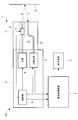
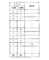
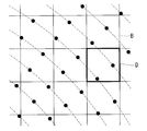
- FIG. 1 is an overall configuration diagram of an optical scanning observation system according to an embodiment of the present invention. It is a block diagram which shows the function of the image processing apparatus with which the optical scanning observation system of FIG. 1 is provided. It is a figure which shows the detection position of observation light and the data of a detection value which are memorize
- FIG. 3 It is a figure which shows an example of the weighting filter used by the weighting part. It is a figure which shows the detection value presence / absence set produced
- an optical scanning observation system 100 includes an optical scanning endoscope apparatus 1, an image processing apparatus 2 connected to the optical scanning endoscope apparatus 1, And a display device 3 connected to the image processing device 2.
- the optical scanning endoscope apparatus 1 includes a light scanning unit 4 that emits laser light (illumination light) L toward the subject A while scanning, and a light detection unit 5 that detects observation light L ′ from the subject A. And a control unit 6 for controlling the light scanning unit 4 and the light detection unit 5.
- Reference numeral 7 denotes an elongated insertion portion inserted into the body, and reference numeral 8 denotes a housing connected to the proximal end of the insertion portion 7.
- the optical scanning unit 4 includes a light source 9 that is provided in the housing 8 and outputs a laser beam L, and an irradiation optical fiber 10 and an actuator 11 that are provided in the insertion unit 7.
- the optical fiber 10 is disposed in the insertion portion 7 along the longitudinal direction.
- the optical fiber 10 guides the laser beam L supplied from the light source 9 and emits it from the tip.
- the actuator 11 is a piezoelectric actuator provided with a piezoelectric element, for example, and is attached to the tip of the optical fiber 10.
- the actuator 11 vibrates the tip of the optical fiber 10 along a spiral trajectory in a substantially plane perpendicular to the longitudinal direction of the optical fiber 10 in accordance with a drive signal supplied from the control unit 6.
- the laser beam L emitted from the tip of the insertion portion 7 is scanned along the spiral scanning locus B on the subject A.
- the scanning trajectory is not limited to a spiral shape, and may be another shape, for example, a raster shape or a Lissajous shape.
- the light detection unit 5 is connected to a proximal end of a light receiving optical fiber 12 disposed in the insertion unit 7.
- the distal end of the optical fiber 12 is disposed on the distal end surface of the insertion portion 7.
- Observation light L ′ (for example, reflected light of laser light L or fluorescence excited by laser light L) generated in subject A by irradiation with laser light L is received at the front end surface of optical fiber 12, and optical fiber 12. Is guided to the light detection unit 5.
- Observation light L ′ for example, reflected light of laser light L or fluorescence excited by laser light L
- a plurality of optical fibers 12 may be provided in the insertion portion 7.
- the light detection unit 5 photoelectrically converts the observation light L ′ received through the optical fiber 12 and samples the generated electrical signal in response to a sampling signal transmitted from the control unit 6 at regular time intervals. Then, a detection value indicating the intensity of the observation light L ′ is obtained by converting it into a digital value. The detection value is transmitted to the detection value frame memory 14 in the image processing apparatus 2.
- the control unit 6 generates a drive signal for driving the actuator 11 and transmits the drive signal to the actuator 11. In addition, the control unit 6 generates a sampling signal at regular time intervals and transmits the sampling signal to the light detection unit 5. The control unit 6 also transmits the drive signal and the sampling signal to the detection position calculation unit 13 in the image processing apparatus 2.
- the image processing apparatus 2 includes a detection position calculation unit 13 that calculates the detection position of the observation light L ′ based on the drive signal and the sampling signal, and data that associates the detection position with the detection value.
- Detection value frame memory (storage unit) 14 a calculation region setting unit 15 for setting a calculation region E used to calculate pixel values, and detection values corresponding to detection positions included in the calculation region E
- a detection value acquisition unit 16 that acquires from the data in the detection value frame memory 14, a weighting unit 17 that weights the detection values acquired from the data, and a pixel value that calculates a pixel value from the weighted detection values
- a calculation unit 18, a pixel value frame memory 19 for storing pixel values, and an image forming unit 20 for forming an image are provided.
- the detection position of the observation light L ′ is coordinates (X, Y) representing the irradiation position on the subject A of the laser light L at the time when the electrical signal of the observation light L ′ is sampled by the light detection unit 5. Since the vibration amplitude of the optical fiber 10 corresponds to the amplitude of the drive signal, the irradiation position of the laser light L can be calculated from the amplitude of the drive signal.
- the detection position calculation unit 13 receives the drive signal and the sampling signal from the control unit 6, and calculates the irradiation position of the laser light L at the output time of the sampling signal from the drive signal. Next, the detection position calculation unit 13 converts the calculated irradiation position into a two-dimensional position coordinate (X, Y), and transmits the coordinate (X, Y) to the detection value frame memory 14 as the detection position. .
- the detection value frame memory 14 receives the detection value of the observation light L ′ from the light detection unit 5, receives the detection position (X, Y) of the observation light L ′ from the detection position calculation unit 13, and receives the observation light L ′. Is detected in association with the detection position (X, Y) when the detection value is sampled. As a result, as shown in FIG. 3, data having the detection position (X, Y) as the address of each detection value is generated in the detection value frame memory 14.
- FIG. 4 is a two-dimensional image of the data.
- the data is two-dimensional data composed of sections C arranged in the X direction (horizontal direction) and the Y direction (vertical direction), and each coordinate corresponds to one section C.
- a section C having a detection value is represented in black
- a section C having no detection value is represented in white.
- the calculation area setting unit 15 sets one of the pixels of the image as a target pixel and sets the calculation area E including the pixel area D.
- the pixel area D is an area on the subject A corresponding to the target pixel.
- black circles indicate the illumination light irradiation positions at the detection value sampling time.
- the size of the calculation region E is set larger than the size of the pixel region D as shown in FIG.
- the size of the calculation area E is set so that at least one detection position is included in the calculation area E based on the minimum density of detection positions in the scanning trajectory B.
- the density of the detection positions in the scanning locus B varies depending on the position in the scanning locus B as will be described later, and can be obtained by calculation from the design value of the optical scanning endoscope apparatus 1.
- the detection position calculation unit 13 calculates the detection position (X, Y) so that the spatial resolution of the coordinates (X, Y) as the detection position is higher than the spatial resolution of the pixel region D. Therefore, a plurality of sections C are included in one pixel region D.
- the spatial resolution of the coordinates (X, Y) is three times the spatial resolution of the pixel area D, and a 3 ⁇ 3 section C is included in one pixel area D.
- the calculation area setting unit 15 sets an area including a predetermined number of sections C around the section C located at the center in the pixel area D as the calculation area E.
- the calculation area E is composed of 7 ⁇ 7 sections C.
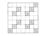
- the detection value acquisition unit 16 selects the detection position (X, Y) included in the calculation region E set by the calculation region setting unit 15 from the data in the detection value frame memory 14, and the selected detection is performed. Detection value sets I 0 , I 1 ,..., I 10 which are detection values corresponding to the position (X, Y) are acquired from the data. FIG. 7 shows an example in which the acquired detection value sets I 0 , I 1 ,..., I 10 are converted into a two-dimensional image. The detection value acquisition unit 16 transmits the acquired detection value set to the weighting unit 17 and the pixel value calculation unit 18.
- the weighting unit 17 has a weighting filter shown in FIG.
- the weighting unit 17 performs a convolution operation on the detected values I 0 , I 1 ,..., I 10 using a weighting filter.
- the convolution operation is expressed by the following equation.
- I ij represents a detection value at a position (i, j) in the calculation area E.
- I 0 is represented as I 07 .
- the weighting coefficients W ij from the center toward the outside so as to be smaller in order, the weight coefficient W ij is set. Therefore, a greater weight is assigned to the detection value closer to the center of the pixel region D.
- the weighting unit 17 transmits the calculated value of the sum Si to the pixel value calculating unit 18.
- the pixel value calculation unit 18 receives the detection position (X, Y) included in the calculation area E from the detection value acquisition unit 16. Next, the pixel value calculation unit 18 generates a detection value presence / absence set shown in FIG. 9 based on the received detection position (X, Y).
- the detection value presence / absence set includes values of “0” and “1” having the same arrangement as that of the section C in the calculation area E. In the detection value presence / absence set, the pixel value calculation unit 18 assigns “1” to a position corresponding to the detection position (X, Y) and assigns “0” to other positions.
- the pixel value calculation unit 18 performs a convolution operation on the detection value presence / absence set using a weighting filter.
- the weighting filter used in the convolution calculation here is the same as the weighting filter used in the weighting unit 17.
- the pixel value calculation unit 18 calculates the pixel value Si / Sw of the target pixel by dividing the sum Si received from the weighting unit 17 by the sum Sw.
- the pixel value calculation unit 18 transmits the calculated pixel value to the pixel value frame memory 19.
- the pixel value frame memory 19 generates image data by storing the pixel value received from the pixel value calculation unit 18 in association with the number N of the target pixel.
- the calculation area setting unit 15 sets all the pixels in the image as the target pixel in order.
- the above-described processing by the detection value acquisition unit 16, the weighting unit 17, and the pixel value calculation unit 18 is executed for all the pixels, and the pixel values of all the pixels are stored in the pixel value frame memory 19.
- the image forming unit 20 reads the image data from the pixel value frame memory 19 and forms an image by assigning a pixel value corresponding to each pixel based on the image data.
- the image forming unit 20 transmits the formed image to the display device 3 and causes the display device 3 to display the image.
- the image processing apparatus 2 includes, for example, a general purpose or dedicated computer including a central processing unit (CPU), a main storage device such as a RAM, and an auxiliary storage device.
- the auxiliary storage device is a non-temporary storage medium such as a hard disk or various memories, and stores an image processing program for causing the CPU to execute the above-described processing.
- the CPU When the image processing program is loaded from the auxiliary storage device to the main storage device and activated, the CPU performs detection position calculation unit 13, calculation region setting unit 15, detection value acquisition unit 16, weighting unit according to the image processing program. 17, the above-described processing of the pixel value calculation unit 18 and the image forming unit 20 is executed.
- the image processing apparatus 2 may be configured using an integrated circuit such as a field programmable gate array (FPGA) instead of the CPU.
- FPGA field programmable gate array
- the optical scanning observation system 100 when transmission of a drive signal and a sampling signal from the control unit 6 to the actuator 11 and the light detection unit 5 is started, the laser light L output from the light source 9 is The object A is irradiated through the optical fiber 10 and scanned along the spiral scanning locus B on the object A.
- the observation light L ′ generated at the irradiation position of the laser light L is received by the optical fiber 12, detected by the light detection unit 5, and the detection value of the observation light L ′ is transmitted to the image processing apparatus 2.
- the drive signal and the sampling signal are also transmitted from the control unit 6 to the image processing apparatus 2.
- FIG. 10 and 11 show an image processing process executed in the image processing apparatus 2.
- the detection position calculation unit 13 receives the drive signal and the sampling signal from the control unit 6, calculates the irradiation position of the laser light L at the sampling time of the detection value from the drive signal, and further expresses the coordinates (X , Y) is calculated as the detection position, and the coordinates (X, Y) are stored in the detection frame memory 14 in association with the detection value from the light detection unit 5.
- the pixel value of each pixel is calculated using the data in the detection frame memory 14 (step S2). That is, as shown in FIG. 11, first, the calculation region setting unit 15 sets a target pixel (step S21), and a calculation region E that includes the pixel region D corresponding to the target pixel and is wider than the pixel region D. It is set (calculation area setting step S22).
- the detection value acquisition unit 16 selects a detection position included in the calculation region E (step S23), and detection value sets I 0 , I 1 ,..., I 10 corresponding to the selected detection position are detected.
- the data is read from the data in the frame memory 14 (detection value acquisition step S24).
- the weighting unit 17 the read detection value sets I 0 , I 1 ,..., I 10 are subjected to a convolution operation using a weighting filter (weighting step S25). Thereby, a greater weight is given to the detection value at the detection position closer to the center of the pixel region D, and the sum Si of the weighted detection values is calculated.
- the pixel value calculation unit 18 generates a detection value presence / absence set from the read detection value sets I 0 , I 1 ,..., I 10 (step S26), and the detection value presence / absence set is used in step S25.
- the convolution operation is performed using the same weighting filter as the weighting filter (step S27). Thereby, the sum Sw of the weights attached to the detected values is calculated.
- the pixel value Si / Sw of the target pixel is calculated by dividing the sum Si by the sum Sw (pixel value calculation step S28).
- the calculated pixel value is stored in the pixel value frame memory 19 in association with the number of the target pixel (step S29).
- step S30 Another pixel is set as the target pixel, and steps S21 to S29 are repeated until all the pixels in the image are set as the target pixel (NO in step S30, step S31).
- the image forming unit 20 reads the image data from the pixel value frame memory 19, and the number in the image data An image is formed by assigning the pixel value to the corresponding pixel based on (Image forming step S3). The formed image is displayed on the display device 3.
- the laser light L is scanned at a constant angular velocity by the optical scanning unit 4, and the observation light L ′ is scanned by the optical detection unit 5 for a certain period of time. Detected at intervals. Accordingly, in the scanning locus B, the density of the detection positions is increased on the center side, and the density of the detection positions is decreased on the outer peripheral side. As a result, a pixel region D that does not include the detection position may occur on the outer peripheral side of the scanning locus B.
- the calculation area E is set so as to include at least one detection position, and the pixel value of the corresponding pixel is calculated from the detection value of the detection position included in the calculation area E. Accordingly, there is an advantage that an image in which all pixels have a pixel value can be formed without a defective pixel having no pixel value.
- the detection position is not necessarily located at the center of the pixel area D, and the distribution of detection positions may be biased in the pixel area D.
- the average of the detection values of the detection positions included in the calculation area E is calculated as the pixel value, a value corresponding to the detection value of the observation light L ′ at a position deviating from the center of the pixel area D is calculated.
- the pixel value is used for forming an image, the image quality is deteriorated, for example, moire occurs in the image.
- a greater weight is given to the detection value at the detection position close to the center of the pixel region D.
- the convolution calculation result Si greatly varies depending on the number of detection values in the detection value set.
- the convolution calculation result Si is normalized by being divided by the convolution calculation result Sw of the detection value presence / absence set and the weighting filter.
- the weighting unit 17 weights the detection value, and then the pixel value calculation unit 18 standardizes the pixel value. Instead, the detection value is weighted. Instead, the pixel value calculation unit 18 may calculate an addition average of the detection value sets I 0 , I 1 ,..., I 10 as a pixel value. This is synonymous with setting all weighting factors W ij to 1 in the weighting unit 17 and the pixel value calculation unit 18. Even in this case, it is possible to eliminate variation in the calculation result of the pixel value with respect to the detection value set in which the detection value does not partially exist.
- the calculation area setting unit 15 sets the calculation area E having a fixed size, but instead, the dimension of the calculation area E can be changed according to the number of detection positions. May be.
- the calculation area setting unit 15 first sets a calculation area E having a small dimension (for example, a dimension equal to the pixel area D), and the number of detection positions included in the calculation area E is equal to or greater than a predetermined number. In this case, this small calculation area E is applied.
- the calculation area E until the number of detection positions included in the calculation area E becomes equal to or greater than the predetermined number. Gradually increase the dimensions of
Landscapes
- Health & Medical Sciences (AREA)
- Life Sciences & Earth Sciences (AREA)
- Surgery (AREA)
- Physics & Mathematics (AREA)
- Optics & Photonics (AREA)
- Medical Informatics (AREA)
- Animal Behavior & Ethology (AREA)
- Radiology & Medical Imaging (AREA)
- Nuclear Medicine, Radiotherapy & Molecular Imaging (AREA)
- Engineering & Computer Science (AREA)
- Biomedical Technology (AREA)
- Heart & Thoracic Surgery (AREA)
- Biophysics (AREA)
- Molecular Biology (AREA)
- Pathology (AREA)
- General Health & Medical Sciences (AREA)
- Public Health (AREA)
- Veterinary Medicine (AREA)
- Astronomy & Astrophysics (AREA)
- General Physics & Mathematics (AREA)
- Endoscopes (AREA)
- Instruments For Viewing The Inside Of Hollow Bodies (AREA)
- Image Processing (AREA)
- Transforming Light Signals Into Electric Signals (AREA)
- Closed-Circuit Television Systems (AREA)
Abstract
画像処理装置(2)は、観察光の検出値および検出位置を対応付けたデータを記憶する記憶部(14)と、画像内の注目画素に対応する被写体における画素領域を含み、かつ、少なくとも1つの検出位置を含む計算領域を設定する計算領域設定部(15)と、計算領域内の検出位置と対応付けられている検出値をデータから取得する検出値取得部(16)と、取得された検出値に基づいて注目画素の画素値を算出する画素値算出部(18)と、画素値を注目画素に割り当てて画像を形成する画像形成部(20)とを備える。
Description
本発明は、画像処理装置、光走査型観察システムおよび画像処理方法に関するものである。
従来、照明光を渦巻状の軌跡に沿って被写体上でスパイラル走査する光走査型内視鏡が知られている(例えば、特許文献1参照。)。光走査型内視鏡は、照明光の照射によって被写体において生じる観察光(例えば、反射光または蛍光)を検出し、観察光の検出値と、観察光が検出された時刻における照明光の照射位置(検出位置)とを対応付けることによって、画像を形成する。被写体上の検出位置の配列と画像内の画素の配列とは互いに異なり、1つの画素に対応する被写体上の画素領域内に複数の検出位置が含まれ得る。特許文献1では、1つの画素領域内に含まれる複数の検出位置における検出値の平均値を、対応する画素の画素値として算出している。
照明光を等角速度で走査するスパイラル走査において、走査軌跡の外周側において検出位置の密度が小さくなる。検出位置の密度が画素領域の密度よりも小さい場合には、検出位置を含まない画素領域が生じる。同様に、モニタ表示画像の走査線に平行でない走査軌跡の撮影や、走査速度が一定でない走査の撮影においても、上記のように検出位置を含まない画素領域を生じる可能性がある。特許文献1の場合、検出位置を含まない画素領域に対応する画素の画素値はゼロと算出される。このような画素値が欠損した欠損画素の画素値を、周囲の画素値から推定して補間する補間処理が知られている。
CCD等のイメージセンサを用いて取得される画像においては、欠損画素がまばらに生じるため、補間処理によって欠損画素の画素値を補間することができる。しかしながら、スパイラル走査方式の画像においては、欠損画素の数が多くなるため、補間処理で欠損画素の画素値を補間することが難しいという問題がある。
本発明は、上述した事情に鑑みてなされたものであって、欠損画素の無い画像を得ることができる画像処理装置、光走査型観察システムおよび画像処理方法を提供することを目的とする。
上記目的を達成するため、本発明は以下の手段を提供する。
本発明の第1の態様は、照明光の照射によって被写体において生じた観察光の検出値および検出位置を対応付けたデータから前記被写体の画像を形成する画像処理装置であって、前記データを記憶する記憶部と、前記画像内の注目画素に対応する前記被写体における画素領域を含む計算領域を設定する計算領域設定部と、該計算領域設定部によって設定された前記計算領域内に含まれる前記検出位置を選択し、選択された前記検出位置と対応付けられている前記検出値を前記データから取得する検出値取得部と、該検出値取得部によって取得された前記検出値に基づいて前記注目画素の画素値を算出する画素値算出部と、該画素値算出部によって算出された画素値を前記注目画素に割り当てて前記画像を形成する画像形成部とを備え、前記計算領域設定部が、前記計算領域内に少なくとも1つの前記検出位置が含まれるように前記計算領域を設定する画像処理装置である。
本発明の第1の態様は、照明光の照射によって被写体において生じた観察光の検出値および検出位置を対応付けたデータから前記被写体の画像を形成する画像処理装置であって、前記データを記憶する記憶部と、前記画像内の注目画素に対応する前記被写体における画素領域を含む計算領域を設定する計算領域設定部と、該計算領域設定部によって設定された前記計算領域内に含まれる前記検出位置を選択し、選択された前記検出位置と対応付けられている前記検出値を前記データから取得する検出値取得部と、該検出値取得部によって取得された前記検出値に基づいて前記注目画素の画素値を算出する画素値算出部と、該画素値算出部によって算出された画素値を前記注目画素に割り当てて前記画像を形成する画像形成部とを備え、前記計算領域設定部が、前記計算領域内に少なくとも1つの前記検出位置が含まれるように前記計算領域を設定する画像処理装置である。
本発明によれば、被写体上の画素領域を含む計算領域が計算領域設定部によって設定され、計算領域内に含まれる検出位置における観察光の検出値が検出値取得部によって記憶部内のデータから取得され、取得された検出値から画像を構成する注目画素の画素値が画素値算出部によって算出される。画像内の各画素を注目画素として画素値が算出され、算出された画素値が画像形成部によって対応する画素に割り当てられることによって、画像が形成される。
この場合に、少なくとも1つの検出位置が計算領域内に含まれるように、画素領域を含む領域が計算領域として計算領域設定部によって設定されるので、検出位置を含む画素領域に対応する画素の画素値のみならず、検出位置を含まない画素領域に対応する画素の画素値も算出される。これにより、欠損画素の無い画像を得ることができる。
本発明の第2の態様は、照明光の照射によって被写体において生じた観察光の検出値および検出位置を対応付けたデータから前記被写体の画像を形成する画像処理装置であって、前記データを記憶する記憶部と、前記画像内の注目画素に対応する前記被写体における画素領域を含む計算領域を設定する計算領域設定部と、該計算領域設定部によって設定された前記計算領域内に含まれる前記検出位置を選択し、選択された前記検出位置と対応付けられている前記検出値を前記データから取得する検出値取得部と、該検出値取得部によって取得された前記検出値に重みを付ける重み付け部と、該重み付け部によって重みを付けられた前記検出値に基づいて前記注目画素の画素値を算出する画素値算出部と、該画素値算出部によって算出された画素値を前記注目画素に割り当てて前記画像を形成する画像形成部とを備え、前記計算領域設定部が、前記計算領域内に少なくとも1つの前記検出位置が含まれるように前記計算領域を設定する画像処理装置である。
上記第2の態様においては、前記重み付け部が、前記画素領域の中心により近い検出位置に対して、より大きな重みを付けてもよい。
このようにすることで、画素領域の中心により近い検出位置における検出値が、計算領域の中心からより遠い検出位置における検出値よりも強く画素値に反映される。これにより、画素領域の中心位置における観察光の検出値を画素値として算出することができる。
このようにすることで、画素領域の中心により近い検出位置における検出値が、計算領域の中心からより遠い検出位置における検出値よりも強く画素値に反映される。これにより、画素領域の中心位置における観察光の検出値を画素値として算出することができる。
上記第2の態様においては、前記画素値算出部が、前記重み付け部によって重みが付けられた前記検出値の和および前記検出値に付けられた重みの和を算出し、前記検出値の和を前記重みの和で除算することによって、前記注目画素の画素値を算出してもよい。
計算領域内に含まれる検出位置の数は一定ではないため、画素値の算出に使用される検出値の数も一定ではない。したがって、重みを付けた検出値の和は、検出値の数によって大きくばらつく。そこで、重みを付けた検出値の和を、検出値に付けた重みの和で除算することによって、規格化された画素値を得ることができる。
計算領域内に含まれる検出位置の数は一定ではないため、画素値の算出に使用される検出値の数も一定ではない。したがって、重みを付けた検出値の和は、検出値の数によって大きくばらつく。そこで、重みを付けた検出値の和を、検出値に付けた重みの和で除算することによって、規格化された画素値を得ることができる。
上記第1および第2の態様においては、前記計算領域設定部が、前記画素領域よりも広い前記計算領域を設定してもよい。
上記第1および第2の態様においては、前記データにおける前記検出位置の空間分解能が、前記被写体における前記画素領域の空間分解能よりも高くてもよい。
このようにすることで、画素値の計算精度を向上することができる。
上記第1および第2の態様においては、前記データにおける前記検出位置の空間分解能が、前記被写体における前記画素領域の空間分解能よりも高くてもよい。
このようにすることで、画素値の計算精度を向上することができる。
上記第1および第2の態様においては、前記計算領域設定部が、前記計算領域内に含まれる前記検出位置の数に応じて前記計算領域の寸法を変更可能であってもよい。
このようにすることで、画素領域および該画素領域の周辺における検出位置の数が少ない場合には、より広い計算領域を設定して、画素値の計算精度を向上することができる。一方、画素領域および該画素領域の周辺における検出位置の数が多い場合には、より狭い計算領域を設定して、画像の解像度の低下を防ぐことができる。
このようにすることで、画素領域および該画素領域の周辺における検出位置の数が少ない場合には、より広い計算領域を設定して、画素値の計算精度を向上することができる。一方、画素領域および該画素領域の周辺における検出位置の数が多い場合には、より狭い計算領域を設定して、画像の解像度の低下を防ぐことができる。
本発明の第3の態様は、照明光を走査しながら被写体に向かって射出する光走査部と、
前記照明光の照射によって前記被写体において発生した観察光を検出し、該観察光の検出値を得る光検出部と、上記いずれかに記載の画像処理装置とを備える光走査型観察システムである。
前記照明光の照射によって前記被写体において発生した観察光を検出し、該観察光の検出値を得る光検出部と、上記いずれかに記載の画像処理装置とを備える光走査型観察システムである。
本発明の第4の態様は、照明光の照射によって被写体において生じた観察光の検出値および検出位置を対応付けたデータから前記被写体の画像を形成する画像処理方法であって、前記データを記憶する記憶ステップと、前記画像内の注目画素に対応する前記被写体における画素領域を含む計算領域を設定する計算領域設定ステップと、該計算領域設定ステップによって設定された前記計算領域内に含まれる前記検出位置を選択し、選択された前記検出位置と対応付けられている前記検出値を前記データから取得する検出値取得ステップと、該検出値取得ステップによって取得された前記検出値に基づいて前記注目画素の画素値を算出する画素値算出ステップと、該画素値算出ステップによって算出された画素値を前記注目画素に割り当てて前記画像を形成する画像形成ステップとを含み、前記計算領域設定ステップにおいて、前記計算領域内に少なくとも1つの前記検出位置が含まれるように前記計算領域を設定する画像処理方法である。
本発明の第5の態様は、照明光の照射によって被写体において生じた観察光の検出値および検出位置を対応付けたデータから前記被写体の画像を形成する画像処理方法であって、前記データを記憶する記憶ステップと、前記画像内の注目画素に対応する前記被写体における画素領域を含む計算領域を設定する計算領域設定ステップと、該計算領域設定ステップによって設定された前記計算領域内に含まれる前記検出位置を選択し、選択された前記検出位置と対応付けられている前記検出値を前記データから取得する検出値取得ステップと、該検出値取得ステップによって取得された前記検出値に重みを付ける重み付けステップと、該重み付けステップによって重みを付けられた前記検出値に基づいて前記注目画素の画素値を算出する画素値算出ステップと、該画素値算出ステップによって算出された画素値を前記注目領域に割り当てて前記画像を形成する画像形成ステップとを含み、前記計算領域設定ステップにおいて、前記計算領域内に少なくとも1つの前記検出位置が含まれるように前記計算領域を設定する画像処理方法である。
本発明によれば、欠損画素の無い画像を得ることができるという効果を奏する。
以下に、本発明の一実施形態に係る光走査型観察システム100について図面を参照して説明する。
本実施形態に係る光走査型観察システム100は、図1に示されるように、光走査型内視鏡装置1と、該光走査型内視鏡装置1に接続された画像処理装置2と、該画像処理装置2に接続された表示装置3とを備えている。
本実施形態に係る光走査型観察システム100は、図1に示されるように、光走査型内視鏡装置1と、該光走査型内視鏡装置1に接続された画像処理装置2と、該画像処理装置2に接続された表示装置3とを備えている。
光走査型内視鏡装置1は、レーザ光(照明光)Lを走査しながら被写体Aに向かって射出する光走査部4と、被写体Aからの観察光L’を検出する光検出部5と、光走査部4および光検出部5を制御する制御部6とを備えている。符号7は、体内に挿入される細長い挿入部を示し、符号8は、挿入部7の基端に接続された筐体を示している。
光走査部4は、筐体8内に設けれレーザ光Lを出力する光源9と、挿入部7内に設けられた照射用の光ファイバ10およびアクチュエータ11とを備えている。
光ファイバ10は、挿入部7内に長手方向に沿って配置されている。光ファイバ10は、光源9から供給されたレーザ光Lを導光し、先端から射出するようになっている。
光ファイバ10は、挿入部7内に長手方向に沿って配置されている。光ファイバ10は、光源9から供給されたレーザ光Lを導光し、先端から射出するようになっている。
アクチュエータ11は、例えば、圧電素子を備える圧電アクチュエータであり、光ファイバ10の先端部に取り付けられている。アクチュエータ11は、制御部6から供給される駆動信号に従って、光ファイバ10の先端を該光ファイバ10の長手方向に直交する略平面内において渦巻状の軌跡に沿って振動させる。これにより、挿入部7の先端から射出されたレーザ光Lが、被写体A上において渦巻状の走査軌跡Bに沿って走査されるようになっている。なお、走査軌跡は、渦巻状に限定されるものではなく、他の形状、例えばラスタ状またはリサージュ状であってもよい。
光検出部5は、挿入部7内に配置された受光用の光ファイバ12の基端と接続されている。光ファイバ12の先端は挿入部7の先端面に配置されている。レーザ光Lの照射によって被写体Aにおいて発生した観察光L’(例えば、レーザ光Lの反射光またはレーザ光Lによって励起された蛍光)は、光ファイバ12の先端面において受光されて、光ファイバ12によって光検出部5まで導光される。図1には光ファイバ12が1本のみ図示されているが、複数本の光ファイバ12が挿入部7内に設けられていてもよい。
光検出部5は、光ファイバ12を介して受光した観察光L’を光電変換し、生成された電気信号を、制御部6から一定の時間間隔で送信されてくるサンプリング信号に応答してサンプリングしてデジタル値に変換することによって、観察光L’の強度を示す検出値を得る。検出値は、画像処理装置2内の検出値用フレームメモリ14に送信される。
制御部6は、アクチュエータ11を駆動させるための駆動信号を発生し、該駆動信号をアクチュエータ11に送信する。また、制御部6は、一定の時間間隔でサンプリング信号を発生し、該サンプリング信号を光検出部5に送信する。制御部6は、駆動信号およびサンプリング信号を画像処理装置2内の検出位置算出部13にも送信する。
画像処理装置2は、図2に示されるように、駆動信号およびサンプリング信号に基づいて観察光L’の検出位置を算出する検出位置算出部13と、検出位置と検出値とを対応付けたデータを記憶する検出値用フレームメモリ(記憶部)14と、画素値の算出に用いられる計算領域Eを設定する計算領域設定部15と、計算領域E内に含まれる検出位置と対応する検出値を検出値用フレームメモリ14内のデータから取得する検出値取得部16と、データから取得された検出値に重みを付ける重み付け部17と、重みが付けられた検出値から画素値を算出する画素値算出部18と、画素値を記憶する画素値用フレームメモリ19と、画像を形成する画像形成部20とを備えている。
観察光L’の検出位置は、観察光L’の電気信号が光検出部5によってサンプリングされた時刻における、レーザ光Lの被写体A上の照射位置を表す座標(X,Y)である。光ファイバ10の振動振幅は、駆動信号の振幅に対応しているので、駆動信号の振幅からレーザ光Lの照射位置を計算することができる。検出位置算出部13は、制御部6から駆動信号およびサンプリング信号を受信し、サンプリング信号の出力時刻におけるレーザ光Lの照射位置を駆動信号から演算する。次に、検出位置算出部13は、算出された照射位置を2次元的な位置座標(X,Y)に変換し、座標(X,Y)を検出位置として検出値用フレームメモリ14に送信する。
検出値用フレームメモリ14は、光検出部5から観察光L’の検出値を受信し、検出位置算出部13から観察光L’の検出位置(X,Y)を受信し、観察光L’の検出値を、該検出値がサンプリングされたときの検出位置(X,Y)と対応付けて記憶する。これにより、検出値用フレームメモリ14には、図3に示されるように、検出位置(X,Y)を各検出値のアドレスとするデータが生成される。
図4は、データを2次元画像化したものである。図4に示されるように、データは、X方向(横方向)およびY方向(縦方向)に配列する区画Cからなる2次元データであり、各座標は1つの区画Cに対応する。図4において、検出値を有する区画Cは黒で表し、検出値を有しない区画Cは白で表している。
計算領域設定部15は、画像の画素の内の1つを注目画素に設定し、画素領域Dを含む計算領域Eを設定する。画素領域Dとは、図5に示されるように、注目画素に対応する被写体A上の領域である。図5において、黒丸は、検出値のサンプリング時刻における照明光の照射位置を示している。計算領域Eの寸法は、図6に示されるように、画素領域Dの寸法よりも大きく設定されている。また、計算領域Eの寸法は、走査軌跡Bにおける検出位置の最小の密度に基づいて、少なくとも1つの検出位置が計算領域Eに含まれるように設定されている。走査軌跡Bにおける検出位置の密度は、後述するように走査軌跡B内の位置に応じて異なり、光走査型内視鏡装置1の設計値から計算で求めることができる。
ここで、検出位置算出部13は、検出位置である座標(X,Y)の空間分解能が、画素領域Dの空間分解能よりも高くなるように、検出位置(X,Y)を算出する。したがって、1つの画素領域D内には複数の区画Cが含まれる。図6に示される例においては、座標(X,Y)の空間分解能が画素領域Dの空間分解能の3倍であり、1つの画素領域D内に3×3の区画Cが含まれている。
計算領域設定部15は、画素領域D内の中心に位置する区画Cを中心とする所定の数の区画Cからなる領域を計算領域Eに設定するようになっている。図6に示される例においては、計算領域Eは、7×7の区画Cからなる。
計算領域設定部15は、画素領域D内の中心に位置する区画Cを中心とする所定の数の区画Cからなる領域を計算領域Eに設定するようになっている。図6に示される例においては、計算領域Eは、7×7の区画Cからなる。
検出値取得部16は、計算領域設定部15によって設定された計算領域E内に含まれる検出位置(X,Y)を検出値用フレームメモリ14内のデータの中から選択し、選択された検出位置(X,Y)に対応する検出値である検出値セットI0,I1,…,I10をデータから取得する。図7は、取得された検出値セットI0,I1,…,I10を2次元画像化した一例を表している。検出値取得部16は、取得された検出値セットを重み付け部17および画素値算出部18に送信する。
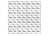
重み付け部17は、図8に示される重み付けフィルタを有している。重み付けフィルタは、計算領域E内の区画Cの配列と同一の配列を有する重み係数Wij(i=0,1,2,…,n、j=0,1,2,…,m)からなる。図8に示される例においては、n=m=6である。重み付け部17は、検出値I0,I1,…,I10に対して、重み付けフィルタを用いて畳み込み演算を行う。畳み込み演算は、下式で表される。下式において、Iijは、計算領域E内の位置(i,j)における検出値を表している。例えば、図7に示される例において、I0は、I07と表される。

ここで、重み付けフィルタにおいて、中心から外側に向かって重み係数Wijが順番に小さくなるように、重み係数Wijが設定されている。したがって、画素領域Dの中心により近い検出値に対して、より大きな重みが付けられるようになっている。
畳み込み演算により、重みWijがそれぞれ付けられた検出値I0,I1,…,I10の和Siが算出される。すなわち、図7および図8の例において、
Si=I0×W06+I1×W12+I2×W15+I3×W21+I4×W24+I5×W42
+I6×W45+I7×W51+I8×W54+I9×W60+I10×W66
である。重み付け部17は、算出された和Siの値を画素値算出部18に送信する。
Si=I0×W06+I1×W12+I2×W15+I3×W21+I4×W24+I5×W42
+I6×W45+I7×W51+I8×W54+I9×W60+I10×W66
である。重み付け部17は、算出された和Siの値を画素値算出部18に送信する。
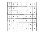
画素値算出部18は、検出値取得部16から、計算領域E内に含まれる検出位置(X,Y)を受信する。次に、画素値算出部18は、受信した検出位置(X,Y)に基づいて、図9に示される検出値有無セットを生成する。検出値有無セットは、計算領域E内の区画Cの配列と同一の配列を有する「0」および「1」の値からなる。画素値算出部18は、検出値有無セットにおいて、検出位置(X,Y)に対応する位置には「1」を割り当て、それ以外の位置には「0」を割り当てる。
次に、画素値算出部18は、検出値有無セットに、重み付けフィルタを用いて畳み込み演算を行う。ここでの畳み込み演算で使用される重み付けフィルタは、重み付け部17で使用される重み付けフィルタと同一である。畳み込み演算により、検出値I0,I1,…,I10に付けられた重み係数と同一の重み係数の和Swが算出される。すなわち、図8および図9の例において、
Sw=W06+W12+W15+W21+W24+W42+W45+W51+W54+W60+W66
である。
Sw=W06+W12+W15+W21+W24+W42+W45+W51+W54+W60+W66
である。
次に、画素値算出部18は、重み付け部17から受信した和Siを、和Swで除算することによって、注目画素の画素値Si/Swを算出する。画素値算出部18は、算出された画素値を画素値用フレームメモリ19に送信する。
画素値用フレームメモリ19は、画素値算出部18から受信した画素値を、注目画素の番号Nと対応付けて記憶することによって、画像データを生成する。ここで、計算領域設定部15は、画像内の全ての画素を順番に注目画素に設定する。これにより、全ての画素に対して検出値取得部16、重み付け部17および画素値算出部18による上述した処理が実行され、画素値用フレームメモリ19には、全ての画素の画素値が記憶される。
画像形成部20は、画素値用フレームメモリ19から画像データを読み出し、画像データに基づき、各画素に対応する画素値を割り当てることによって画像を形成する。画像形成部20は、形成した画像を表示装置3に送信し、該表示装置3に表示させる。
画像処理装置2は、例えば、中央演算処理装置(CPU)と、RAMのような主記憶装置と、補助記憶装置とを備える汎用または専用のコンピュータからなる。補助記憶装置は、ハードディスクまたは各種のメモリのような非一時的な記憶媒体であり、上述した処理をCPUに実行させるための画像処理プログラムを格納している。画像処理プログラムが、補助記憶装置から主記憶装置にロードされて起動されることによって、CPUが、画像処理プログラムに従って、検出位置算出部13、計算領域設定部15、検出値取得部16、重み付け部17、画素値算出部18および画像形成部20の上述した処理を実行するようになっている。
あるいは、画像処理装置2は、CPUではなく、フィールド・プログラマブル・ゲート・アレイ(FPGA)等の集積回路を用いて構成されていてもよい。
あるいは、画像処理装置2は、CPUではなく、フィールド・プログラマブル・ゲート・アレイ(FPGA)等の集積回路を用いて構成されていてもよい。
次に、このように構成された光走査型観察システム100の作用について説明する。
本実施形態に係る光走査型観察システム100において、制御部6からアクチュエータ11および光検出部5へ駆動信号およびサンプリング信号の送信がそれぞれ開始されると、光源9から出力されたレーザ光Lが、光ファイバ10を介して被写体Aへ照射され、被写体A上においてスパイラル状の走査軌跡Bに沿って走査される。レーザ光Lの照射位置において発生した観察光L’は、光ファイバ12によって受光され、光検出部5によって検出され、観察光L’の検出値が画像処理装置2に送信される。一方、駆動信号およびサンプリング信号も、制御部6から画像処理装置2へ送信される。
本実施形態に係る光走査型観察システム100において、制御部6からアクチュエータ11および光検出部5へ駆動信号およびサンプリング信号の送信がそれぞれ開始されると、光源9から出力されたレーザ光Lが、光ファイバ10を介して被写体Aへ照射され、被写体A上においてスパイラル状の走査軌跡Bに沿って走査される。レーザ光Lの照射位置において発生した観察光L’は、光ファイバ12によって受光され、光検出部5によって検出され、観察光L’の検出値が画像処理装置2に送信される。一方、駆動信号およびサンプリング信号も、制御部6から画像処理装置2へ送信される。
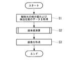
図10および図11は、画像処理装置2内で実行される画像処理プロセスを示している。
画像処理装置2内において、まず、図10に示されるように、観察光L’の検出値と検出位置とを対応付けたデータが検出用フレームメモリ14内に生成および記憶される(記憶ステップS1)。すなわち、検出位置算出部13において、制御部6からの駆動信号およびサンプリング信号が受信され、駆動信号から検出値のサンプリング時刻におけるレーザ光Lの照射位置が算出され、さらに照射位置を表す座標(X,Y)が検出位置として算出され、座標(X,Y)が、光検出部5からの検出値と対応付けて検出用フレームメモリ14に記憶される。
画像処理装置2内において、まず、図10に示されるように、観察光L’の検出値と検出位置とを対応付けたデータが検出用フレームメモリ14内に生成および記憶される(記憶ステップS1)。すなわち、検出位置算出部13において、制御部6からの駆動信号およびサンプリング信号が受信され、駆動信号から検出値のサンプリング時刻におけるレーザ光Lの照射位置が算出され、さらに照射位置を表す座標(X,Y)が検出位置として算出され、座標(X,Y)が、光検出部5からの検出値と対応付けて検出用フレームメモリ14に記憶される。
次に、検出用フレームメモリ14内のデータを用いて各画素の画素値が演算される(ステップS2)。すなわち、図11に示されるように、まず、計算領域設定部15において、注目画素が設定され(ステップS21)、注目画素に対応する画素領域Dを含み該画素領域Dよりも広い計算領域Eが設定される(計算領域設定ステップS22)。
次に、検出値取得部16において、計算領域E内に含まれる検出位置が選択され(ステップS23)、選択された検出位置に対応する検出値セットI0,I1,…,I10が検出用フレームメモリ14内のデータから読み出される(検出値取得ステップS24)。
次に、重み付け部17において、読み出された検出値セットI0,I1,…,I10が、重み付けフィルタを用いて畳み込み演算される(重み付けステップS25)。これにより、画素領域Dの中心により近い検出位置における検出値にはより大きな重みが付けられるとともに、重みが付けられた検出値の和Siが算出される。
次に、重み付け部17において、読み出された検出値セットI0,I1,…,I10が、重み付けフィルタを用いて畳み込み演算される(重み付けステップS25)。これにより、画素領域Dの中心により近い検出位置における検出値にはより大きな重みが付けられるとともに、重みが付けられた検出値の和Siが算出される。
次に、画素値算出部18において、読み出された検出値セットI0,I1,…,I10から検出値有無セットが生成され(ステップS26)、検出値有無セットが、ステップS25において用いた重み付けフィルタと同一の重み付けフィルタを用いて畳み込み演算される(ステップS27)。これにより、検出値に付けられた重みの和Swが算出される。次に、和Siを和Swで除算することによって、注目画素の画素値Si/Swが算出される(画素値算出ステップS28)。算出された画素値は、注目画素の番号と対応付けて画素値用フレームメモリ19に記憶される(ステップS29)。
次に、他の画素を注目画素に設定して、画像内の全ての画素が注目画素に設定されるまで(ステップS30のNO、ステップS31)、ステップS21~S29が繰り返される。全ての画素に対する画素値が画素値用フレームメモリ19に記憶されると(ステップS30のYES)、画像形成部20によって、画素値用フレームメモリ19から画像データを読み出され、画像データ内の番号に基づいて画素値が対応する画素に割り当てられることによって、画像が形成される(画像形成ステップS3)。形成された画像は、表示装置3に表示される。
この場合に、レーザ光Lをスパイラル走査する光走査内視鏡装置1において、レーザ光Lは光走査部4によって等角速度で走査され、かつ、観察光L’は光検出部5によって一定の時間間隔で検出される。したがって、走査軌跡Bのうち、中心側において検出位置の密度が高くなり、外周側において検出位置の密度が低くなる。その結果、走査軌跡Bの外周側において、検出位置を含まない画素領域Dが生じ得る。
本実施形態によれば、少なくとも1つの検出位置を含むように計算領域Eが設定され、計算領域E内に含まれる検出位置の検出値から、対応する画素の画素値が算出される。これにより、画素値が存在しない欠損画素が生じることがなく、全ての画素が画素値を有する画像を形成することができるという利点がある。
さらに、計算領域E内において、検出位置が画素領域Dの中心に位置するとは限らず、検出位置の分布が画素領域D内で偏り得る。各画素の正確な画素値を得るためには、計算領域E内における検出値の分布を考慮し、画素領域Dの中心における観察光L’の検出値を算出する必要がある。計算領域E内に含まれる検出位置の検出値の平均を画素値として算出した場合、画素領域Dの中心から外れた位置における観察光L’の検出値に相当する値が算出され、このような画素値を画像の形成に用いた場合には、画像内にモアレが生じる等、画質の低下を招く。
本実施形態によれば、画素値の計算において、画素領域Dの中心に近い検出位置の検出値に対してより大きな重みが付される。これにより、各画素の正確な画素値を算出することができ、質の高い画像を得ることができるという利点がある。
さらに、図7および図8に示されるように、一部の重み係数Wijには、対応する検出値が存在しない。このように部分的に検出値が存在しない検出値セットに対して重み付けフィルタを適用する際に、検出値セット内の検出値の数に応じて畳み込み演算結果Siが大きくばらつく。本実施形態によれば、この畳み込み演算結果Siが、検出値有無セットと重み付けフィルタとの畳み込み演算結果Swで除算されることによって、規格化される。これにより、重み付けフィルタを用いて検出値の重み付けを適切に行うことができるという利点がある。
本実施形態においては、重み付け部17によって検出値に重みを付け、その後に画素値算出部18によって規格化することにより画素値を算出することとしたが、これに代えて、検出値の重み付けを行わず、画素値算出部18が、検出値セットI0,I1,…,I10の加算平均を画素値として算出してもよい。これは、重み付け部17および画素値算出部18において、全ての重み係数Wijの値を1にすることと同義である。
このようにしても、部分的に検出値が存在しない検出値セットに対して、画素値の演算結果のばらつきを排除することができる。
このようにしても、部分的に検出値が存在しない検出値セットに対して、画素値の演算結果のばらつきを排除することができる。
本実施形態においては、計算領域設定部15が、固定の寸法の計算領域Eを設定することとしたが、これに代えて、検出位置の数に応じて計算領域Eの寸法を変更可能であってもよい。
例えば、計算領域設定部15は、最初に小さな寸法(例えば、画素領域Dと等しい寸法)の計算領域Eを設定し、該計算領域E内に含まれる検出位置の数が所定の数以上である場合には、この小さな寸法の計算領域Eを適用する。一方、小さな寸法の計算領域E内に含まれる検出位置の数が所定の数未満である場合には、計算領域E内に含まれる検出位置の数が所定の数以上となるまで、計算領域Eの寸法を段階的に拡大する。
例えば、計算領域設定部15は、最初に小さな寸法(例えば、画素領域Dと等しい寸法)の計算領域Eを設定し、該計算領域E内に含まれる検出位置の数が所定の数以上である場合には、この小さな寸法の計算領域Eを適用する。一方、小さな寸法の計算領域E内に含まれる検出位置の数が所定の数未満である場合には、計算領域E内に含まれる検出位置の数が所定の数以上となるまで、計算領域Eの寸法を段階的に拡大する。
計算領域Eの寸法が大きい程、画像の解像度は低下する。したがって、計算領域Eの寸法を、欠損画素の発生を防ぐことができる最小限の寸法に抑えることによって、画像の解像度の低下を防ぐことができる。
1 光走査型内視鏡装置
2 画像処理装置
3 表示装置
4 光走査部
5 光検出部
6 制御部
7 挿入部
8 筐体
9 光源
10,12 光ファイバ
11 アクチュエータ
13 検出位置算出部
14 検出値用フレームメモリ(記憶部)
15 計算領域設定部
16 検出値取得部
17 重み付け部
18 画素値算出部
19 画素値用フレームメモリ
20 画像形成部
100 光走査型観察システム
A 被写体
B 走査軌跡
C 区画
D 画素領域
E 計算領域
L レーザ光(照明光)
L’ 観察光
2 画像処理装置
3 表示装置
4 光走査部
5 光検出部
6 制御部
7 挿入部
8 筐体
9 光源
10,12 光ファイバ
11 アクチュエータ
13 検出位置算出部
14 検出値用フレームメモリ(記憶部)
15 計算領域設定部
16 検出値取得部
17 重み付け部
18 画素値算出部
19 画素値用フレームメモリ
20 画像形成部
100 光走査型観察システム
A 被写体
B 走査軌跡
C 区画
D 画素領域
E 計算領域
L レーザ光(照明光)
L’ 観察光
Claims (10)
- 照明光の照射によって被写体において生じた観察光の検出値および検出位置を対応付けたデータから前記被写体の画像を形成する画像処理装置であって、
前記データを記憶する記憶部と、
前記画像内の注目画素に対応する前記被写体における画素領域を含む計算領域を設定する計算領域設定部と、
該計算領域設定部によって設定された前記計算領域内に含まれる前記検出位置を選択し、選択された前記検出位置と対応付けられている前記検出値を前記データから取得する検出値取得部と、
該検出値取得部によって取得された前記検出値に基づいて前記注目画素の画素値を算出する画素値算出部と、
該画素値算出部によって算出された画素値を前記注目画素に割り当てて前記画像を形成する画像形成部とを備え、
前記計算領域設定部が、前記計算領域内に少なくとも1つの前記検出位置が含まれるように前記計算領域を設定する画像処理装置。 - 照明光の照射によって被写体において生じた観察光の検出値および検出位置を対応付けたデータから前記被写体の画像を形成する画像処理装置であって、
前記データを記憶する記憶部と、
前記画像内の注目画素に対応する前記被写体における画素領域を含む計算領域を設定する計算領域設定部と、
該計算領域設定部によって設定された前記計算領域内に含まれる前記検出位置を選択し、選択された前記検出位置と対応付けられている前記検出値を前記データから取得する検出値取得部と、
該検出値取得部によって取得された前記検出値に重みを付ける重み付け部と、
該重み付け部によって重みを付けられた前記検出値に基づいて前記注目画素の画素値を算出する画素値算出部と、
該画素値算出部によって算出された画素値を前記注目画素に割り当てて前記画像を形成する画像形成部とを備え、
前記計算領域設定部が、前記計算領域内に少なくとも1つの前記検出位置が含まれるように前記計算領域を設定する画像処理装置。 - 前記重み付け部が、前記画素領域の中心により近い検出位置に対して、より大きな重みを付ける請求項2に記載の画像処理装置。
- 前記画素値算出部が、前記重み付け部によって重みが付けられた前記検出値の和および前記検出値に付けられた重みの和を算出し、前記検出値の和を前記重みの和で除算することによって、前記注目画素の画素値を算出する請求項2または請求項3に記載の画像処理装置。
- 前記計算領域設定部が、前記画素領域よりも広い前記計算領域を設定する請求項1から請求項4のいずれかに記載の画像処理装置。
- 前記データにおける前記検出位置の空間分解能が、前記被写体における前記画素領域の空間分解能よりも高い請求項1から請求項5のいずれかに記載の画像処理装置。
- 前記計算領域設定部が、前記計算領域内に含まれる前記検出位置の数に応じて前記計算領域の寸法を変更可能である請求項1から請求項6のいずれかに記載の画像処理装置。
- 照明光を走査しながら被写体に向かって射出する光走査部と、
前記照明光の照射によって前記被写体において発生した観察光を検出し、該観察光の検出値を得る光検出部と、
請求項1から請求項7のいずれかに記載の画像処理装置とを備える光走査型観察システム。 - 照明光の照射によって被写体において生じた観察光の検出値および検出位置を対応付けたデータから前記被写体の画像を形成する画像処理方法であって、
前記データを記憶する記憶ステップと、
前記画像内の注目画素に対応する前記被写体における画素領域を含む計算領域を設定する計算領域設定ステップと、
該計算領域設定ステップによって設定された前記計算領域内に含まれる前記検出位置を選択し、選択された前記検出位置と対応付けられている前記検出値を前記データから取得する検出値取得ステップと、
該検出値取得ステップによって取得された前記検出値に基づいて前記注目画素の画素値を算出する画素値算出ステップと、
該画素値算出ステップによって算出された画素値を前記注目画素に割り当てて前記画像を形成する画像形成ステップとを含み、
前記計算領域設定ステップにおいて、前記計算領域内に少なくとも1つの前記検出位置が含まれるように前記計算領域を設定する画像処理方法。 - 照明光の照射によって被写体において生じた観察光の検出値および検出位置を対応付けたデータから前記被写体の画像を形成する画像処理方法であって、
前記データを記憶する記憶ステップと、
前記画像内の注目画素に対応する前記被写体における画素領域を含む計算領域を設定する計算領域設定ステップと、
該計算領域設定ステップによって設定された前記計算領域内に含まれる前記検出位置を選択し、選択された前記検出位置と対応付けられている前記検出値を前記データから取得する検出値取得ステップと、
該検出値取得ステップによって取得された前記検出値に重みを付ける重み付けステップと、
該重み付けステップによって重みを付けられた前記検出値に基づいて前記注目画素の画素値を算出する画素値算出ステップと、
該画素値算出ステップによって算出された画素値を前記注目領域に割り当てて前記画像を形成する画像形成ステップとを含み、
前記計算領域設定ステップにおいて、前記計算領域内に少なくとも1つの前記検出位置が含まれるように前記計算領域を設定する画像処理方法。
Priority Applications (2)
| Application Number | Priority Date | Filing Date | Title |
|---|---|---|---|
| JP2017555909A JPWO2017104002A1 (ja) | 2015-12-15 | 2015-12-15 | 画像処理装置、光走査型観察システムおよび画像処理方法 |
| PCT/JP2015/085106 WO2017104002A1 (ja) | 2015-12-15 | 2015-12-15 | 画像処理装置、光走査型観察システムおよび画像処理方法 |
Applications Claiming Priority (1)
| Application Number | Priority Date | Filing Date | Title |
|---|---|---|---|
| PCT/JP2015/085106 WO2017104002A1 (ja) | 2015-12-15 | 2015-12-15 | 画像処理装置、光走査型観察システムおよび画像処理方法 |
Publications (1)
| Publication Number | Publication Date |
|---|---|
| WO2017104002A1 true WO2017104002A1 (ja) | 2017-06-22 |
Family
ID=59056207
Family Applications (1)
| Application Number | Title | Priority Date | Filing Date |
|---|---|---|---|
| PCT/JP2015/085106 Ceased WO2017104002A1 (ja) | 2015-12-15 | 2015-12-15 | 画像処理装置、光走査型観察システムおよび画像処理方法 |
Country Status (2)
| Country | Link |
|---|---|
| JP (1) | JPWO2017104002A1 (ja) |
| WO (1) | WO2017104002A1 (ja) |
Citations (1)
| Publication number | Priority date | Publication date | Assignee | Title |
|---|---|---|---|---|
| WO2015145826A1 (ja) * | 2014-03-28 | 2015-10-01 | オリンパス株式会社 | 走査型内視鏡装置 |
-
2015
- 2015-12-15 WO PCT/JP2015/085106 patent/WO2017104002A1/ja not_active Ceased
- 2015-12-15 JP JP2017555909A patent/JPWO2017104002A1/ja active Pending
Patent Citations (1)
| Publication number | Priority date | Publication date | Assignee | Title |
|---|---|---|---|---|
| WO2015145826A1 (ja) * | 2014-03-28 | 2015-10-01 | オリンパス株式会社 | 走査型内視鏡装置 |
Also Published As
| Publication number | Publication date |
|---|---|
| JPWO2017104002A1 (ja) | 2018-10-04 |
Similar Documents
| Publication | Publication Date | Title |
|---|---|---|
| JP6137847B2 (ja) | 撮像装置及び撮像装置の制御方法 | |
| US10379329B2 (en) | Microscope system and setting value calculation method | |
| JP5490331B1 (ja) | 内視鏡システム | |
| AU2018352821B2 (en) | Image reconstruction method, device and microscopic imaging device | |
| JP6736670B2 (ja) | 内視鏡システム | |
| JP6203109B2 (ja) | 光走査型画像形成装置及び光走査型画像形成方法 | |
| JP6594101B2 (ja) | 画像処理装置、画像処理方法および画像処理プログラム | |
| JP6626117B2 (ja) | 光走査装置および光走査装置の制御方法 | |
| JP6630432B2 (ja) | 距離画像処理装置、距離画像取得装置、及び距離画像処理方法 | |
| JP5638890B2 (ja) | 撮像装置、撮像方法及びプログラム | |
| WO2012029658A1 (ja) | 撮像装置、画像処理装置、画像処理方法及び画像処理プログラム | |
| WO2021014799A1 (ja) | 信号処理装置、信号処理方法 | |
| WO2017056599A1 (ja) | 画像作成装置および画像作成方法 | |
| JP6776692B2 (ja) | 視差演算システム、移動体及びプログラム | |
| WO2016132778A1 (ja) | スペックルイメージング装置、スペックルイメージングシステム及びスペックルイメージング方法 | |
| WO2017104002A1 (ja) | 画像処理装置、光走査型観察システムおよび画像処理方法 | |
| JP2010131112A (ja) | 内視鏡装置 | |
| JP7030986B2 (ja) | 画像生成装置、画像生成方法および画像生成プログラム | |
| JP5829198B2 (ja) | 超音波検査装置、超音波検査装置の信号処理方法およびプログラム | |
| US12579621B2 (en) | Optical image processing method, machine learning method, trained model, machine learning pre-processing method, optical image processing module, optical image processing program, and optical image processing system | |
| JP6422761B2 (ja) | 顕微鏡システム、及び、z位置と補正装置の設定値との関係算出方法 | |
| JP7229210B2 (ja) | 内視鏡用プロセッサ及び内視鏡システム | |
| CN117616451A (zh) | 一种光学图像处理方法、机器学习方法、训练后的模型、机器学习的预处理方法、光学图像处理模块、光学图像处理程序和光学图像处理系统 | |
| JP6595858B2 (ja) | 画像処理装置及び画像処理方法 | |
| WO2017056898A1 (ja) | 超音波診断装置及び受信データ処理方法 |
Legal Events
| Date | Code | Title | Description |
|---|---|---|---|
| 121 | Ep: the epo has been informed by wipo that ep was designated in this application |
Ref document number: 15910693 Country of ref document: EP Kind code of ref document: A1 |
|
| ENP | Entry into the national phase |
Ref document number: 2017555909 Country of ref document: JP Kind code of ref document: A |
|
| NENP | Non-entry into the national phase |
Ref country code: DE |
|
| 122 | Ep: pct application non-entry in european phase |
Ref document number: 15910693 Country of ref document: EP Kind code of ref document: A1 |