WO2017101856A1 - 驱动组件以及空调器 - Google Patents
驱动组件以及空调器 Download PDFInfo
- Publication number
- WO2017101856A1 WO2017101856A1 PCT/CN2016/110376 CN2016110376W WO2017101856A1 WO 2017101856 A1 WO2017101856 A1 WO 2017101856A1 CN 2016110376 W CN2016110376 W CN 2016110376W WO 2017101856 A1 WO2017101856 A1 WO 2017101856A1
- Authority
- WO
- WIPO (PCT)
- Prior art keywords
- door panel
- mount
- drive
- driving
- rack
- Prior art date
- Legal status (The legal status is an assumption and is not a legal conclusion. Google has not performed a legal analysis and makes no representation as to the accuracy of the status listed.)
- Ceased
Links
Images




Classifications
-
- F—MECHANICAL ENGINEERING; LIGHTING; HEATING; WEAPONS; BLASTING
- F24—HEATING; RANGES; VENTILATING
- F24F—AIR-CONDITIONING; AIR-HUMIDIFICATION; VENTILATION; USE OF AIR CURRENTS FOR SCREENING
- F24F1/00—Room units for air-conditioning, e.g. separate or self-contained units or units receiving primary air from a central station
-
- F—MECHANICAL ENGINEERING; LIGHTING; HEATING; WEAPONS; BLASTING
- F24—HEATING; RANGES; VENTILATING
- F24F—AIR-CONDITIONING; AIR-HUMIDIFICATION; VENTILATION; USE OF AIR CURRENTS FOR SCREENING
- F24F13/00—Details common to, or for air-conditioning, air-humidification, ventilation or use of air currents for screening
- F24F13/08—Air-flow control members, e.g. louvres, grilles, flaps or guide plates
- F24F13/10—Air-flow control members, e.g. louvres, grilles, flaps or guide plates movable, e.g. dampers
- F24F13/12—Air-flow control members, e.g. louvres, grilles, flaps or guide plates movable, e.g. dampers built up of sliding members
-
- F—MECHANICAL ENGINEERING; LIGHTING; HEATING; WEAPONS; BLASTING
- F24—HEATING; RANGES; VENTILATING
- F24F—AIR-CONDITIONING; AIR-HUMIDIFICATION; VENTILATION; USE OF AIR CURRENTS FOR SCREENING
- F24F1/00—Room units for air-conditioning, e.g. separate or self-contained units or units receiving primary air from a central station
- F24F1/0007—Indoor units, e.g. fan coil units
- F24F1/0011—Indoor units, e.g. fan coil units characterised by air outlets
-
- F—MECHANICAL ENGINEERING; LIGHTING; HEATING; WEAPONS; BLASTING
- F24—HEATING; RANGES; VENTILATING
- F24F—AIR-CONDITIONING; AIR-HUMIDIFICATION; VENTILATION; USE OF AIR CURRENTS FOR SCREENING
- F24F11/00—Control or safety arrangements
-
- F—MECHANICAL ENGINEERING; LIGHTING; HEATING; WEAPONS; BLASTING
- F24—HEATING; RANGES; VENTILATING
- F24F—AIR-CONDITIONING; AIR-HUMIDIFICATION; VENTILATION; USE OF AIR CURRENTS FOR SCREENING
- F24F11/00—Control or safety arrangements
- F24F11/70—Control systems characterised by their outputs; Constructional details thereof
-
- F—MECHANICAL ENGINEERING; LIGHTING; HEATING; WEAPONS; BLASTING
- F24—HEATING; RANGES; VENTILATING
- F24F—AIR-CONDITIONING; AIR-HUMIDIFICATION; VENTILATION; USE OF AIR CURRENTS FOR SCREENING
- F24F13/00—Details common to, or for air-conditioning, air-humidification, ventilation or use of air currents for screening
- F24F13/08—Air-flow control members, e.g. louvres, grilles, flaps or guide plates
- F24F13/10—Air-flow control members, e.g. louvres, grilles, flaps or guide plates movable, e.g. dampers
-
- F—MECHANICAL ENGINEERING; LIGHTING; HEATING; WEAPONS; BLASTING
- F24—HEATING; RANGES; VENTILATING
- F24F—AIR-CONDITIONING; AIR-HUMIDIFICATION; VENTILATION; USE OF AIR CURRENTS FOR SCREENING
- F24F13/00—Details common to, or for air-conditioning, air-humidification, ventilation or use of air currents for screening
- F24F13/20—Casings or covers
-
- F—MECHANICAL ENGINEERING; LIGHTING; HEATING; WEAPONS; BLASTING
- F16—ENGINEERING ELEMENTS AND UNITS; GENERAL MEASURES FOR PRODUCING AND MAINTAINING EFFECTIVE FUNCTIONING OF MACHINES OR INSTALLATIONS; THERMAL INSULATION IN GENERAL
- F16H—GEARING
- F16H19/00—Gearings comprising essentially only toothed gears or friction members and not capable of conveying indefinitely-continuing rotary motion
- F16H19/02—Gearings comprising essentially only toothed gears or friction members and not capable of conveying indefinitely-continuing rotary motion for interconverting rotary or oscillating motion and reciprocating motion
- F16H19/04—Gearings comprising essentially only toothed gears or friction members and not capable of conveying indefinitely-continuing rotary motion for interconverting rotary or oscillating motion and reciprocating motion comprising a rack
-
- F—MECHANICAL ENGINEERING; LIGHTING; HEATING; WEAPONS; BLASTING
- F24—HEATING; RANGES; VENTILATING
- F24F—AIR-CONDITIONING; AIR-HUMIDIFICATION; VENTILATION; USE OF AIR CURRENTS FOR SCREENING
- F24F2221/00—Details or features not otherwise provided for
- F24F2221/26—Details or features not otherwise provided for improving the aesthetic appearance
Definitions
- the present invention relates to the field of air conditioning technology, and in particular, to a driving assembly and an air conditioner.
- a drive component including
- a door panel driving assembly mounted on the mounting seat and connected to the door panel to drive the door panel to operate between an open state and a closed state;
- the mounting seat being movably disposed on the base
- mount drive assembly disposed between the base and the mount, and when the door panel is in a closed state, driving the mount to drive the door panel between a closed position and a disengaged position relative to the door opening mobile.
- the mount drive assembly includes an actuating mechanism that drives movement of the mount relative to the base, and a guide stop mechanism that is disposed in a predetermined path to guide movement of the mount.
- the actuating mechanism includes a mount actuating gear mounted on one of the mount or the base, fixedly disposed on the mount or the other base and The mount actuating gear engages the mount actuating rack and the mount actuating gear power structure that drives the mount actuating gear to rotate in the forward and reverse directions.
- the guiding limit mechanism includes a seat disposed on one of the mount or the base a guiding limit slot, and a head is located in the seat guiding limiting slot, and a tail portion protrudes from a slot of the seat guiding limiting slot and is fixed to a guiding limit on the mounting seat or the other base
- the seat guiding limiting groove has two guiding side walls which are oppositely arranged to guide the movement of the head head, and two opposite limiting side walls for limiting the head position, and two The guiding sidewall cooperates with the two limiting sidewalls to form a limiting cavity for limiting the head, and the notch communicates with the limiting cavity.
- the guide limiting member includes a roller shaft disposed on the mounting seat or the other base, and is mounted on the roller shaft in the seat guiding limiting slot. The first roller.
- one of the facing faces of the mounting seat or the base is provided with a supporting rail groove parallel to a predetermined path of the guiding limiting mechanism, the mounting seat or the base Another support roller rotatably disposed for rolling in the support rail groove.
- an electronic control system controls the door panel driving component to drive the door panel to switch from the open state to the closed state, stop driving the door panel driving component, and simultaneously control the
- the mount drive assembly drives the mount to move toward the closed position; or controls the mount drive assembly to drive the mount to move to the disengaged position, stop continuing to drive the mount drive assembly, and simultaneously control the door panel
- the drive assembly drives the door panel to transition from a closed state to an open state.
- the electronic control system includes an inductor for detecting movement of the door panel to a closed state, and a controller that controls the door panel drive assembly to drive the door panel to be switched from an open state to
- the sensor is triggered after the state is turned off, the controller stops the door panel driving assembly after receiving the trigger signal, and simultaneously controls the mount driving assembly to drive the mount to move toward the closed position; or the controller controls After the mount driving assembly drives the mount to move away from the disengaged position for a preset time, stopping to continue driving the mount drive assembly, and simultaneously controlling the door panel drive assembly to drive the door panel to switch from the closed state to the open state .
- the door panel drive assembly includes a door panel drive gear mounted on a top of the mount; a door panel drive rack movably mounted on the mount, the door panel drive gear meshing with the door panel drive gear, a door panel driving rack is coupled to the door panel; and a door panel driving power mechanism that drives the door panel driving gear to rotate in a forward direction and a reverse direction.
- the door panel driving rack is slidably mounted by a rack guiding limit groove formed on the mounting seat.
- the door panel driving rack is rotatably provided with a plurality of second rollers, and the second roller is placed in the rack guiding limiting slot to roll and move.
- the mounting base includes a seat body, and a cover portion that is engaged with the seat body, the seat body is provided with a guiding rail on a surface of the cover portion, and the cover portion is a position of the guide rail corresponding to the direction of the guide rail, the slot width being narrower than the width of the door panel driving rack, and the guiding rail after the cover portion is engaged with the seat body
- the rack guiding limit groove is formed with the through groove, and the through groove is for the connecting portion to protrude.
- the connecting portion is provided with two, respectively disposed at two ends of the door panel driving rack.
- the door panel driving rack is a curved rack or a straight rack.
- An air conditioner comprising a panel assembly having a door opening, a door panel movably disposed at the door opening, the door opening forming an air outlet of the air conditioner, and two sets of the above-mentioned driving components, wherein the two sets of the driving components are respectively connected At both ends of the door panel.
- the door panel is formed by a grille and a baffle, wherein the door panel moves to an open state when the grille is aligned with the air outlet, and moves to the baffle and the It is off when the air is aligned.
- the mount by positioning the mount on the base, when the door panel is moved to the closed state, the mount is driven by the mount drive assembly to move the door panel to the closed position with the door opening closed. Therefore, the gap between the door panel and the door opening can be closed, which not only has good appearance consistency, but also prevents dust from entering.
- the air conditioner of the present invention has the driving assembly of the present invention, when the air outlet is closed, the black seam is not seen at the edge of the door panel, thereby not only ensuring the consistency of the appearance, but also preventing the dust to a certain extent. Enter the inside of the air outlet.
- Figure 1 is a front elevational view of the panel assembly provided by the present invention in an operating state of the air conditioner
- Figure 2 is a left side view of Figure 1;
- Figure 3 is a rear elevational view of Figure 1;
- Figure 4 is a front elevational view of the panel assembly provided by the present invention when the air conditioner is stopped;
- Figure 5 is a top plan view of the panel assembly of the air conditioner of Figure 1 in a disengaged state
- Figure 6 is a plan view showing the panel assembly of the air conditioner of Figure 1 and the main body casing in a fitted state;
- FIG. 7 is a schematic exploded view of a drive assembly in accordance with an embodiment of the present invention.
- FIG. 8 is a schematic structural view of a slide rail assembly according to an embodiment of the present invention.
- Figure 9 is a plan view of Figure 8.
- Figure 10 is a front elevational view of Figure 8.
- FIG. 11 is a schematic exploded view of a drive assembly in another embodiment of the present invention.
- FIG. 12 is a schematic exploded view of a drive assembly in another embodiment of the present invention.
- Figure 13 is an enlarged schematic view of a portion A in Figures 11 and 12;
- Figure 14 is an enlarged schematic view of a portion B of Figures 11 and 12;
- Figure 15 is a front elevational view of the first mounting seat of Figure 11 and Figure 12 mated with the rollers;
- Figure 16 is a perspective view of the first mounting seat of Figure 11 and Figure 12 in cooperation with the rollers;
- Figure 17 is a perspective view of the first mounting seat of Figure 11 and Figure 12 in cooperation with the respective rollers;
- Figure 18 is a schematic view showing the assembled structure of a drive assembly in an embodiment of the present invention.
- a first embodiment of the present invention provides an air conditioner including a main body housing, an air outlet assembly 100, a panel assembly 200, and a drive assembly 300.
- the air outlet assembly 100 is disposed on the main body casing
- the panel assembly 200 is disposed outside the main body casing.
- the panel assembly 200 is pivotally disposed outside of the main body housing.
- the drive assembly 300 is preferably a panel assembly moving component.
- the drive assembly 300 drives the panel assembly 200 to expose the air outlet assembly 100 in a state where the air conditioner is in operation.
- the drive assembly 300 drives the panel assembly 200 to close and approach the main housing until it comes into contact with the main housing.
- the gap H is about 5-10 mm in the design.
- the panel assembly 200 is in a disengaged state from the main body casing; as shown in FIG. 6, the panel assembly 200 is in contact with the main body casing, and the panel assembly 200 is in a state of being fitted to the main body casing, and the gap H is 0 mm.
- the drive assembly 300 can drive the panel assembly 200 to close and approach the main body casing until the air conditioner stops working until it comes into contact with the main body casing.
- the air conditioner can make a gap between the panel assembly 200 and the main body casing, so that the air conditioner has better aesthetic appearance and can reduce dust from entering the air conditioner.
- the drive assembly 300 can include a first drive device 310 , a first gear 320 , and a first rack 330 .
- the first driving device 310 drives the first gear 320 to rotate.
- the first rack 330 meshes with the first gear 320 and the first rack 330 is coupled to the panel assembly 200.
- the first gear 320 drives the first rack 330 to move.
- the first rack 330 re-drives the panel assembly 200 toward or away from the mainframe housing.
- the rotating shaft of the first driving device 310 may be embedded in the first gear 320 to drive the first gear 320 to rotate.
- the first driving device 310 can drive the first gear 320 to rotate according to a preset program.
- the first driving device 310 can be a first stepper motor.
- the rotating shaft of the first stepping motor drives the first gear 320 to rotate.
- the drive assembly 300 can also include a second drive 360, a second gear 370, and a second rack 380.
- the second driving device 360 drives the second gear 370 to rotate.
- the second gear 370 drives the second rack 380 to move in the circumferential direction of the main body casing.
- the second rack 380 is coupled to the panel assembly 200 to drive the panel assembly 200 in the main body housing The movement in the circumferential direction.
- the second rack 380 may have an arc shape.
- the second driving device 360, the second gear 370 and the second rack 380 are disposed, so that when the air conditioner is working, the panel assembly 200 opens the preset width to expose the air outlet component 100, that is, the panel assembly 200 is opened; the air conditioner stops working. When the panel assembly 200 is closed; and the air conditioner is swept left and right in the working state.
- the second drive device 360 can be a second stepper motor.
- the rotating shaft of the second stepping motor is embedded in the second gear 370 to drive the second gear 370 to rotate.
- the drive assembly 300 includes a first mount 341 and a second mount 342.
- the position of the first mount 341 is fixed relative to the position of the panel assembly 200.
- the first mounting seat 341 can be fixedly disposed on the main body housing.
- the first driving device 310 and the first gear 320 are disposed on the first mounting seat 341.
- the first mount 341 may be provided with a receiving cavity corresponding to the outer shape of the first driving device 310.
- the first driving device 310 is disposed in the receiving cavity.
- the first gear 320 may be disposed on the first mount 341 by means of snapping or screwing.
- the second mount 342 is movably disposed on the first mount 341.
- the first rack 330 is disposed on the second mount 342.
- the second mount 342 is coupled to the panel assembly 200.
- the first rack 330 can drive the second mount 342 to move relative to the first mount 341 to move the panel assembly 200 toward or away from the main housing.
- the second mount 342 can be disposed on the first mount 341 by a first degree of freedom moving structure. Providing the first degree of freedom moving structure can reduce the frictional force when the first mount 341 and the second mount 342 are relatively moved.
- the first degree of freedom motion structure may be a rail assembly 350.
- the first degree of freedom that the rail assembly 350 limits is the degree of freedom in the direction in which the panel assembly 200 is near or away from the mainframe housing.
- the rail assembly 350 can include an outer rail 351, an inner rail 352, and a steel ball 353.
- the inner rail 352 is disposed in a region surrounded by the inner wall of the outer rail 351.
- the inner rail 352 is connected to the first mount 341, and the outer rail 351 is connected to the second mount 342.
- a steel ball 353 is disposed between the outer rail 351 and the inner rail 352.
- the outer rail 351 and the inner rail 352 are relatively moved by the steel balls 353.
- the relative movement of the outer rail 351 and the inner rail 352 is achieved because the steel ball 353 is rolled. Therefore, the slide rail assembly 350 can greatly reduce the frictional force when the relative movement between the first mount 341 and the second mount 342 is relatively.
- the number of the steel balls 353 may be plural.
- the plurality of steel balls 353 are evenly distributed between the outer rail 351 and the inner rail 352, so that the movement between the outer rail 351 and the inner rail 352 can be made more stable.
- the slide rail assembly 350 may further include a limiting structure 354.
- a stop structure 354 is disposed between the inner rail 352 and the outer rail 351.
- the stop structure 354 can be disposed on the inner rail 352 or on the outer rail 351.
- the stop structure 354 limits the area of motion of the steel ball 353.
- the number of the limiting structures 354 may be multiple, and are respectively disposed at two ends of the inner rail 352 or both ends of the outer rail 351.
- the moving area of the steel ball 353 is made to constitute a closed space, and the steel ball 353 can be better prevented from falling off between the outer rail 351 and the inner rail 352.
- the outer rail 351 may be coupled to the first mount 341, and the inner rail 352 may be coupled to the second mount 342.
- the above-described connection manner also enables the rail assembly 350 to achieve the effect of reducing the frictional force when the first mount 341 and the second mount 342 are relatively moved.
- the first degree of freedom motion structure may also be other structures.
- the first degree of freedom moving structure includes a first guiding limit groove 357 and a first guiding limit member.
- the first guiding limiting slot 357 is disposed on the second mounting seat 342.
- the head of the guiding limiting member is located in the first guiding limiting slot 357, and the tail portion is protruded from the notch of the first guiding limiting slot 357 of the seat and is fixed on the first mounting seat 341.
- the first guiding limiting slot 357 of the seat has opposite guiding sidewalls for guiding the movement of the head, and oppositely disposed, two limiting sidewalls for limiting the head, and two The guiding sidewall cooperates with the two limiting sidewalls to form a limiting cavity for limiting the head, and the notch communicates with the limiting cavity.
- the first guiding limiting slot 357 has a plurality of structures, and may be a guiding groove having a "T" shape in cross section, or a guiding groove having a "ten” shape in cross section, and the guiding limiting member may be a limiting position.
- the first guiding limiting member comprises a first roller shaft 356 disposed on the first mounting seat 341, and is mounted on the first roller shaft 356 at the first guiding limiting slot
- the first roller 355 in 357.
- the upper end of the first roller shaft 356 is provided with a mushroom head structure.
- the first roller 355 is nested on the first roller shaft 356.
- the mushroom head structure serves to prevent the first roller 355 from being withdrawn from the first roller shaft 356.
- the number of the first guiding limiting slots 357 is three, and is relatively uniformly disposed on the first mounting seat 341.
- the first degree of freedom motion structure in this embodiment can also limit the first degree of freedom in the direction in which the panel assembly 200 is near or away from the mainframe housing. Moreover, the frictional force during the relative movement between the first mount 341 and the second mount 342 can also be reduced.
- the first guiding limiting slot 357 may be disposed on the first mounting seat 341, and the first guiding limiting member may be disposed on the second mounting seat 342.
- the first mount 341 is provided with a support rail slot parallel to a predetermined path of movement of the second mount 342. 393.
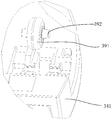
- the second mounting seat 342 is provided with a rotatable supporting roller 391.
- the supporting roller 391 is rotatably disposed on the second mounting seat 342 by a supporting roller shaft 392, and the supporting roller 391 is at The support rail groove 393.
- the number of the support rail grooves 393 and the support rollers 391 is four.
- a support rail groove 393 is provided at the bottom of the second mount 342, and a support roller 391 is disposed on the top of the first mount 341 via the support roller shaft 392.
- Such a structural arrangement can reduce the contact area between the first mount 341 and the second mount 342, thereby reducing The friction between the two makes the second mount 342 move more flexible and stable.
- the support rail groove 393 may be disposed on the first mount 341, and the support roller 391 may be disposed on the second mount 342.
- the second driving device 360 , the second gear 370 and the second rack 380 are disposed on the second mounting seat 342 .
- the second driving device 360 and the second gear 370 are fixed on the second mounting seat 342, and the second rack 380 is movable relative to the second mounting seat 342.
- the drive assembly 300 also includes a second degree of freedom motion assembly, the second rack 380 being mounted to the second mount 342 by a second degree of freedom motion assembly. Providing the second degree of freedom motion structure can reduce the frictional force when the second rack 380 and the second mount 342 are in relative motion.
- the second degree of freedom moving assembly includes a guiding track 410 disposed on the second mounting seat 342 and a second roller 412 rotatably disposed on the second rack 380, the second roller 412 being Rolling on the guide rail 410 to drive the second rack 380 to move on the guide rail 410.
- the second roller 412 is rotatably disposed on the second rack 380 by a second roller shaft.
- the guiding track 410 may be arcuate. The provision of the second roller 412 can reduce the frictional contact surface between the second rack 380 and the guide rail 410, thereby making the movement of the second rack 380 on the guide rail 410 more flexible.
- the second degree of freedom defined by the guide track 410 is the degree of freedom of the panel assembly 200 in the circumferential direction of the mainframe housing.
- the second rack 380 may be provided with a connecting portion 440 for fixed connection with the panel assembly 200.
- the connecting portion 440 is provided with two, which are respectively disposed at two ends of the second rack 380.
- the second mounting seat 342 can be disposed with the second guiding limiting slot 420.
- the second rack 380 is located in the second guiding limiting slot 420 and can be moved in the second guiding limiting slot 420.
- the second guiding limiting slot 420 is configured to guide the movement of the second rack 380 to ensure smooth and smooth opening or closing of the panel assembly 200, and at the same time, can limit the second rack 380 to the second guiding limiting slot.
- the second rack 380 is prevented from being detached from the second mount 342.
- the width of the second guide limiting groove 420 is narrower than the width of the second rack 380, so that the second rack 380 can be further prevented from being detached from the second mounting seat 342.
- a third roller 414 is disposed on the second rack 380.
- the third roller 414 is disposed in the second guiding limiting slot 420 and can roll in the second guiding limiting slot 420.
- the arrangement of the third roller 414 can reduce the frictional contact surface between the second rack 380 and the second guide limiting slot 420, so that the movement of the second rack 380 in the second guiding limiting slot 420 is more flexible.
- the third roller 414 can be disposed on the second rack 380 through the third roller shaft.
- the second mounting seat 342 includes a seat body 343 and a cover portion 344 that is engaged with the seat body 343.
- the cover portion 344 can be fastened to the seat body 343 by snapping or screwing.
- the second gear 350 and the second rack 370 may be disposed on the seat body 343.
- the second driving device 360 may be disposed on the cover portion 344.
- the cover portion 344 may be provided with a receiving cavity corresponding to the outer shape of the second driving device 360.
- the second driving device 360 is disposed in the receiving cavity.
- the guide rail 410 is disposed on the seat body 343.
- a through slot corresponding to the guiding track 410 is disposed at a position corresponding to the guiding track 410 on the cover portion 344. After the seat body 343 is engaged with the cover portion 344, the through slot That is, the second guide limit groove 420 is formed.
- the through groove may also extend out of the connecting portion 440.
- the number of the driving components 300 is two.
- Two drive assemblies 300 are respectively disposed at upper and lower ends of the main body housing. Both drive assemblies 300 are coupled to panel assembly 200. This can make the movement of the panel assembly 200 relative to the main body housing more stable.
- the first driving device 310 drives the first gear 320 to rotate, thereby driving the first rack 330 to move.
- the first rack 330 drives the panel assembly 200 away from the mainframe housing until the panel assembly 200 reaches the working position.
- the second driving device 360 drives the second gear 370 to rotate, thereby driving the second rack 380 to move.
- the second rack 380 drives the panel assembly 200 to move along the circumferential direction of the main body casing, thereby opening the panel assembly 200 to a predetermined width, exposing the wind assembly 100, and realizing the functions of sweeping the wind left and right.
- the second driving device 360 drives the second gear 370 to rotate, thereby driving the second rack 380 to move.
- the second rack 380 moves the panel assembly 200 in the circumferential direction of the main body casing, and can also close the panel assembly 200.
- the first driving device 310 drives the first gear 320 to rotate, thereby driving the first rack 330 to move.
- the first rack 330 drives the panel assembly 200 toward the main housing until the panel assembly 200 is attached to the main housing.
- the panel assembly moving part 300 can also control the movement of the panel assembly 200 by: the panel assembly moving part 300 includes a motor, a first sprocket driven by the motor, and a mechanism provided with the second sprocket; The first sprocket and the second sprocket are connected by a chain, and the mechanism provided with the second sprocket is fixedly connected with the panel assembly 200; the motor, the first sprocket and the mechanism provided with the second sprocket can be fixed to the host through the fixing component On the housing.
- the driving assembly 300 of the present invention further includes an electronic control system, and the electronic control system controls the second driving device 360 to drive the panel assembly 200 to stop driving after the panel unit 200 is switched from the on state to the off state.
- a driving device 360 and simultaneously controlling the first driving device 310 to drive the panel assembly 200 to move toward the host housing; or controlling the first driving device 310 to drive the panel assembly 200 to a disengaged position, stopping
- the first driving device 310 is continuously driven, and at the same time, the second driving device 320 is controlled to drive the panel assembly 200 to be switched from the off state to the on state.
- the electronic control system includes an inductor 500 for detecting movement of the panel assembly to a closed state, and a controller that controls the second driving device 360 to drive the panel assembly
- the sensor 500 is triggered after the state transitions from the on state to the off state, the controller stops the second driving device 360 after receiving the trigger signal, and simultaneously controls the first driving device 310 to drive the panel assembly 200 Moving toward the closed position; or the controller controls the first driving component 310 to drive the panel assembly 200 to move toward the disengaged position direction for a preset time, stopping to continue driving the first driving component 310, and simultaneously controlling the
- the second drive assembly 360 drives the panel assembly 200 to transition from a closed state to an open state.
- the inductor 500 is a micro switch.
- the electronic control system only Including an inductor 500, such an arrangement can save manufacturing costs.
- the electronic control system may further include two inductors 500, that is, by adding another inductor 500 to detect that the panel assembly 200 is moved into position in the disengaged position instead of according to the panel assembly 200.
- the closed position direction is moved by a preset time to judge that the movement of the panel assembly 200 is in place.
- a second embodiment of the present invention provides a driving assembly 300, an air outlet device, and an air conditioner.
- the air outlet device includes a panel assembly 200 having a door opening.
- the difference is that the air outlet assembly 100 is a door panel 100 disposed at the door opening, and the driving assembly 300 drives the door panel 100 in a state where the air conditioner is in operation. Moving to the first position, the air conditioner vents air from the door opening.
- the drive assembly 300 drives the door panel 100 to move to the second position and approaches the panel assembly 200 until the door panel 100 is fitted to the panel assembly 200.
- the drive assembly 300 can drive the door panel 100 to close the door opening and approach the panel assembly 200 until the panel assembly 200 comes into contact when the air conditioner stops operating.
- the air conditioner can make a gap between the panel assembly 200 and the main body casing, so that the air conditioner has better aesthetic appearance and can reduce dust from entering the air conditioner.
- the driving component 300 is a driving structure that realizes the door panel 100 without gap closure, and includes:
- a door panel driving assembly mounted on the mounting seat 342 and connected to the door panel 100 to drive the door panel 100 to operate between a first position (open state) and a second position (closed state);
- the base 341 is fixedly disposed with respect to the panel assembly 200 having the door opening, and the mounting seat 342 is movably disposed on the base 341;
- a mounting seat assembly disposed between the base 341 and the mounting seat 342, and when the door panel 100 is in the second position, driving the mounting seat 342 to drive the door panel 100 toward or away from the panel assembly 200, moving the door panel 100 between a closed position and a disengaged position relative to the door opening.
- the above solution is the core solution of the second embodiment.
- the mounting seat 342 is movably disposed on the base 341
- the mounting seat 342 is driven by the mount driving assembly to drive the door panel 100 to move to
- the closed position of the door opening is closed (ie, moving toward the panel assembly 200 until the door panel 100 is in close contact with the panel assembly 200), so that the door panel 100 and the door opening can be closed without gaps, and the appearance consistency is good. It prevents dust from entering.
- the gap H is about 5-10 mm in the design.
- the door panel 100 is closed. In the fitted state, the gap H between the door panel 100 and the panel assembly 200 becomes 0 mm.
- the mount drive assembly includes an actuating mechanism that drives the mount 342 to move relative to the base 341, and a guide limit mechanism that is disposed in a predetermined path to guide the movement of the mount 342.
- the actuating mechanism includes a mount actuating gear 320 mounted on one of the mounting seat 342 or the base 341, and is fixedly disposed in the mounting.
- a seat 342 or a mount on the other side of the base 341 that engages with the mount actuating gear 320 actuates the rack 330, and a mount that drives the mount actuating gear 320 to rotate in the forward and reverse directions Gear power structure.
- the mounting mechanism of the actuating gear includes a second motor 310, and the second motor 310 drives the mounting actuating gear 320 to rotate, thereby driving the mounting actuating rack 330 to linearly reciprocate, thereby driving the mounting seat 342 to the closed position. Move (ie, near the panel assembly 200) or away from the position (ie, away from the panel assembly 200).
- the electronic control system controls the operation of the mount drive assembly by controlling the rotation of the second motor 310.
- the guiding and limiting mechanism comprises a mounting on the one of the mounting base 342 or the base 341.
- the seat guide limiting slot 357, and the head is located in the seat guiding limiting slot 357, and the tail portion protrudes from the slot of the seat guiding limiting slot 357 and is fixed to the mounting seat 342 or the base 341.
- An upper guiding stop member, the seat guiding limiting slot 357 has two guiding side walls, which are opposite to each other, and a relative arrangement, and a limit on the head position Positioning the sidewalls, and the two guiding sidewalls cooperate with the two limiting sidewalls to form a limiting cavity for limiting the head, and the notch communicates with the limiting cavity.
- the seat guiding limit groove has a plurality of structures, and may be a guide groove having a cross section of "T" shape, or a guide groove having a cross section of "ten” shape, and the guide limit member may be limited to " A T-shaped guide groove or a "T" shaped piece in a "T” shaped guide groove.
- the guiding limiting member comprises a roller shaft 356 disposed on the other of the mounting seat 342 or the base 341, and is mounted on the roller shaft 356 at the seat guiding The first roller 355 in the limiting slot 357.
- the guiding stopper of such a structure can ensure that the mounting seat 342 moves back and forth on the base 341 smoothly and flexibly.
- one of the facing faces of the mounting seat 342 or the base 341 is provided with a supporting rail groove 393 parallel to a predetermined path of the guiding limiting mechanism.
- the mounting seat 342 or the other of the base 341 is rotatably disposed on a support roller 391 adapted to roll in the support rail groove 393.
- This structural arrangement can reduce the contact area between the mount 342 and the base 341, thereby reducing the friction between the two, and making the mount 342 move more flexible and stable.
- the support rail groove 393 is provided at the bottom of the mount 342, and the support roller 391 is disposed on the top of the base 341 by the support roller shaft 392.
- a driving structure for realizing the door panel without gap closure of the embodiment further includes an electronic control system, and the electronic control system controls the door panel driving component to drive the door panel 100 to be stopped after being turned from the open state to the closed state.
- the electronic control system controls the door panel driving component to drive the door panel 100 to be stopped after being turned from the open state to the closed state.
- the electronic control system includes a sensor for detecting that the door panel 100 is moved to a closed state. 500, and a controller, the controller controls the door panel driving component to drive the door panel 100 to switch from an open state to a closed state, the sensor 500 is triggered, and the controller stops the door panel driving after receiving a trigger signal And simultaneously controlling the mount drive assembly to drive the mount 342 to move toward the closed position; or the controller controls the mount drive assembly to drive the mount 342 to move toward the disengaged position for a predetermined time, Stop driving the mount drive assembly and simultaneously control the door panel drive assembly to drive the door panel 100 from the closed state to the open state.
- the inductor 500 is a micro switch.
- the electronic control system includes only one inductor 500, and the arrangement can save manufacturing costs.
- the electronic control system may further include two inductors 500, that is, by adding another inductor 500 to detect that the mounting seat 342 is moved into position in the disengaged position instead of the mounting base 342.
- the closed position direction is moved by a preset time to judge that the movement of the mount 342 is in place.
- the door panel drive assembly has a plurality of structures.
- the door panel drive assembly preferably includes a door panel drive gear 370 mounted on the top of the mount 342; a seat panel 342, a door panel driving the gantry driving gear 370, the door panel driving rack 380 being coupled to the door panel 100, and a door panel driving power for driving the door panel driving gear 370 to rotate in the forward and reverse directions Agency 360.
- the door panel driving rack 380 is slidably mounted by a rack guiding limit groove 420 formed on the mounting seat 342.
- the door driving rack 380 is located in the rack guiding limiting slot 420, and the connecting portion 440 of the door driving rack 380 and the door panel 100 is from the slot of the rack guiding limiting slot 420 Outwardly extending, the slot width of the rack guiding limiting slot 420 is narrower than the width of the door panel driving rack 380.
- the rack guiding limit groove 420 is disposed to guide the movement of the door driving rack 380 to ensure the smooth opening and closing of the door panel 100, and at the same time, the door driving rack 380 can be restrained in the rack guiding limit slot 420. Inside, the door panel driving rack 380 is prevented from being detached from the mounting seat 342.
- the door panel driving power mechanism 360 includes a first motor that drives the door panel driving gear 370 through the first motor, thereby driving the door panel driving rack 380 to move back and forth, thereby driving the door panel 100 to open or close.
- the door panel driving rack 380 may be a curved rack or a straight rack. When the door panel 100 is a curved door panel, the door panel driving rack 380 is a curved rack.
- the electronic control system controls the operation of the door panel drive assembly by controlling the rotation of the first motor.
- the mounting base includes a seat body 343 and a cover portion 344 that is engaged with the seat body 343, the seat body A guiding rail 410 is disposed on a surface of the cover portion 344, and a position of the cover portion 344 corresponding to the guiding rail 410 is aligned with the guiding rail 410, and the slot width is narrower than the door panel. a slot for driving the width of the rack 380.
- the rack guide 410 and the through slot form the rack guide limiting slot 420.
- the groove is extended by the connecting portion 440.
- the connecting portion 440 is provided at two ends, which are respectively disposed at two ends of the door panel driving rack 380.
- a plurality of second rollers 414 are rotatably disposed on the door driving rack 380, and the second roller 414 is placed in the rack guiding limiting slot 420 to roll.
- the arrangement of the second roller 414 can reduce the door panel driving rack 380
- the frictional contact surface with the rack guide limiting slot 420 allows the movement of the door panel driving rack 380 within the rack guiding limiting slot 420 to be more flexible.
- an air outlet device of the present invention includes a panel assembly 200 having a door opening, and a door panel 100 movably disposed at the door opening, the door opening forming an air outlet 220 of the air outlet structure.
- the air outlet structure of the present invention has the drive structure 300 for achieving the door panel without gap closure as described above, and therefore, not only can the motion gap remain during opening, closing, and sweeping, but also when the air outlet 220 is closed, the door panel 100
- the panel assembly 200 is in close contact with the panel assembly 200, so that there is no gap between the door panel 100 and the air outlet 220, and the appearance is good, and at the same time, dust can be prevented from entering the air outlet structure.
- the door panel 100 is formed by the grille 120 and the baffle 110, wherein the door panel 100 is moved to an open state when the grille 120 is aligned with the air outlet 220, and moved to the baffle 110 and the When the air outlet 220 is aligned, it is in a closed state, and when the driving grille 120 is swung left and right, a wind sweeping process is realized.
- An air conditioner of the present invention has the air outlet device as described above, so that when the air conditioner is closed, there is no black seam at the edge of the door panel 100, thereby not only ensuring the consistency of the appearance of the air conditioner. To a certain extent, it can prevent dust from entering the interior of the air conditioner.
- the process of closing and closing the door panel 100 the controller controls the first motor to drive the door panel driving gear 370 to rotate, and the door panel driving gear 370 drives the door panel driving rack 380 to rotate, so as to drive the door panel 100 to move, so that the shutter 110 of the door panel 100 is aligned with the panel assembly 200.
- the upper air outlet 220 after the door panel 100 is in the closed state, triggers the sensor 500, the controller stops continuing to drive the first motor, and simultaneously controls the second motor 310 to drive the mount actuator gear 320 to rotate, and the mount actuating gear 320 drives The mount actuating rack 330 moves, thereby driving the mount 342 toward the panel assembly 200 until the door panel 100 is in close contact with the panel assembly 200.
- the opening process the controller controls the second motor 310 to drive the mounting actuating gear 320 to rotate in the reverse direction, and the mounting actuating gear 320 drives the mounting actuating rack 330 to move back, thereby driving the mounting seat 342 away from the panel assembly.
- the controller stops driving the second motor 310, and simultaneously controls the first motor to drive the door driving gear 370 to rotate in the reverse direction, and the door driving gear 370 drives the door driving rack 380 to rotate back to drive the door panel.
- the 100 moves back so that the grille 120 on the door panel 100 is aligned with the air outlet 220 on the panel assembly 200 to open the air outlet 220. When it is necessary to sweep the wind left and right, the drive grill 120 is moved to the left and right.
- the base 341 and the mounting seat 342 are substantially the same as the first mounting seat 341 and the second mounting seat 342 of the first embodiment, respectively; the seat body 343 and the cover portion 344 are respectively associated with the first embodiment.
- the seat body 343 and the cover portion 344 are substantially the same; the second motor 310, the mount actuating gear 320, and the mount actuating rack 330 are respectively coupled to the first driving device 310, the first gear 320, and the first embodiment of the first embodiment.
- a rack 330 is substantially identical; the first motor 320, the door drive gear 370, and the door drive rack 380 are respectively coupled to the second drive unit 360, the second gear 370, and the second rack 380 base of the first embodiment.
- the seat guide limiting slot 357 and the guiding limiting member are substantially the same as the first guiding limiting slot 357 and the first guiding limiting member of the first embodiment; respectively, the first roller 355 and the roller shaft 356 are respectively first
- the first roller 355 of the embodiment is substantially identical to the first roller shaft 356; the support rail groove 393, the support roller 391, and the support roller shaft 392 are basically the same as the support rail groove 393, the support roller 391, and the support roller shaft 392 of the first embodiment, respectively.
- the electronic control system and the sensor 500 are substantially the same as the electronic control system and the sensor 500 of the first embodiment; the guide rail 410 and the rack guide limit slot 420 are respectively associated with the guide rail 410 and the second embodiment of the first embodiment;
- the guide limit groove 420 is substantially the same; the second roller 414 is substantially the same as the third roller 414 of the first embodiment; the same components are not described herein again.
Landscapes
- Engineering & Computer Science (AREA)
- Chemical & Material Sciences (AREA)
- Combustion & Propulsion (AREA)
- Mechanical Engineering (AREA)
- General Engineering & Computer Science (AREA)
- Transmission Devices (AREA)
- Air Filters, Heat-Exchange Apparatuses, And Housings Of Air-Conditioning Units (AREA)
- Air-Flow Control Members (AREA)
Abstract
Description
Claims (16)
- 一种驱动组件,其特征在于,包括安装座;门板驱动组件,安装在所述安装座上,用于与门板连接,驱动所述门板在开启状态与关闭状态之间移动;底座,相对于具有门洞的面板组件位置固定地设置,所述安装座可移动地设置在所述底座上;安装座驱动组件,设置在所述底座与所述安装座之间,在所述门板处于关闭状态时,驱动所述安装座来带动所述门板在相对所述门洞的闭合位置与脱离位置之间移动。
- 根据权利要求1所述的驱动组件,其特征在于,所述安装座驱动组件包括驱动所述安装座相对所述底座移动的致动机构,以及按预定路径设置,对所述安装座的移动进行导向的导向限位机构。
- 根据权利要求2所述的驱动组件,其特征在于,所述致动机构包括安装在所述安装座或所述底座之一上的安装座致动齿轮,固定设置在所述安装座或所述底座另一个上并与所述安装座致动齿轮啮合的安装座致动齿条,以及驱动所述安装座致动齿轮正、反方向旋转的安装座致动齿轮动力结构。
- 根据权利要求3所述的驱动组件,其特征在于,所述导向限位机构包括设置在所述安装座或所述底座之一上的座导向限位槽,以及头部处于所述座导向限位槽内,尾部从所述座导向限位槽的槽口伸出后固定在所述安装座或所述底座另一个上的导向限位件,所述座导向限位槽具有相对设置的,对所述头部移动进行导向的两导向侧壁,以及相对设置,对所述头部进行限位的两限位侧壁,且两所述导向侧壁与两所述限位侧壁配合形成对所述头部限位的限位腔,且所述槽口与所述限位腔相通。
- 根据权利要求4所述的驱动组件,其特征在于,所述导向限位件包括设置在所述安装座或所述底座另一个上的滚轮轴,以及安装在所述滚轮轴上,处于所述座导向限位槽内的第一滚轮。
- 根据权利要求2所述的驱动组件,特征在于,所述安装座或所述底座的两者相向面之一上设置有与所述导向限位机构的预定路径平行的支承导轨槽,所述安装座或所述底座的另一个上转动地设置的适于在所述支承导轨槽中滚动的支承滚轮。
- 根据权利要求1所述的驱动组件,其特征在于,还包括电控系统,所述电控系统控制所述门板驱动组件驱动所述门板由开启状态转换到关闭状态后,停止继续驱动所述门板驱动组件,并同时控制所述安装座驱动组件驱动所述安装座朝闭合位置移动;或控制所述安装座驱动组件驱动所述安装座移动到脱离位置后,停止 继续驱动所述安装座驱动组件,并同时控制所述门板驱动组件驱动所述门板由关闭状态转换到开启状态。
- 根据权利要求7所述的驱动组件,其特征在于,所述电控系统包括用于检测所述门板移动至关闭状态的感应器,以及控制器,所述控制器控制所述门板驱动组件驱动所述门板由开启状态转换到关闭状态后触发所述感应器,所述控制器接收到触发信号后停止所述门板驱动组件,并同时控制所述安装座驱动组件驱动所述安装座朝闭合位置移动;或所述控制器控制所述安装座驱动组件驱动所述安装座朝脱离位置方向移动预设时间后,停止继续驱动所述安装座驱动组件,并同时控制所述门板驱动组件驱动所述门板由关闭状态转换到开启状态。
- 根据权利要求1-8中任一项所述的驱动组件,其特征在于,所述门板驱动组件包括安装在所述安装座顶部上的门板驱动齿轮;活动安装在所述安装座上,与所述门板驱动齿轮啮合的门板驱动齿条,所述门板驱动齿条与所述门板连接;以及驱动所述门板驱动齿轮正、反方向旋转的门板驱动动力机构。
- 根据权利要求9所述的驱动组件,其特征在于,所述门板驱动齿条通过成型在所述安装座上的齿条导向限位槽滑动地安装。
- 根据权利要求10所述的驱动组件,其特征在于,所述门板驱动齿条上转动地设有若干第二滚轮,所述第二滚轮置于所述齿条导向限位槽内滚动移动。
- 根据权利要求10所述的驱动组件,其特征在于,所述安装座包括座体,以及与所述座体扣合的盖部,所述座体朝向所述盖部的表面上设有导向轨道,所述盖部上与所述导向轨道对应的位置处设有走向与所述导向轨道走向一致,槽宽窄于所述门板驱动齿条宽度的通槽,所述盖部与所述座体扣合后,所述导向轨道与所述通槽之间形成所述齿条导向限位槽,所述通槽供所述连接部伸出。
- 根据权利要求12所述的驱动组件,其特征在于,所述连接部设有两个,分别设置于所述门板驱动齿条的两端。
- 根据权利要求10所述的驱动组件,其特征在于,所述门板驱动齿条为弧形齿条或直齿条。
- 一种空调器,包括具有门洞的面板组件,活动设置在所述门洞处的门板,所述门洞形成所述空调器的出风口,其特征在于,还具有两套如权利要求1-14中任一项所述的驱动组件,两套所述驱动组件分别连接于所述门板的两端。
- 根据权利要求15所述的一种空调器,其特征在于,所述门板由格栅和挡板相接形成,其中所述门板移动至所述格栅与所述出风口对准时为开启状态,移动至所述挡板与所述出风对准时为关闭状态。
Priority Applications (2)
| Application Number | Priority Date | Filing Date | Title |
|---|---|---|---|
| KR1020187012247A KR102307438B1 (ko) | 2015-12-18 | 2016-12-16 | 구동 조립체 및 공기 조화기 |
| JP2018519410A JP6592194B2 (ja) | 2015-12-18 | 2016-12-16 | 駆動部品及びエアコン |
Applications Claiming Priority (4)
| Application Number | Priority Date | Filing Date | Title |
|---|---|---|---|
| CN201521071080.6U CN205299736U (zh) | 2015-12-18 | 2015-12-18 | 空调器 |
| CN201521071080.6 | 2015-12-18 | ||
| CN201610578628.9 | 2016-07-20 | ||
| CN201610578628.9A CN106052064A (zh) | 2016-07-20 | 2016-07-20 | 一种实现门板无间隙关闭的驱动结构及出风装置及空调器 |
Publications (1)
| Publication Number | Publication Date |
|---|---|
| WO2017101856A1 true WO2017101856A1 (zh) | 2017-06-22 |
Family
ID=59055728
Family Applications (1)
| Application Number | Title | Priority Date | Filing Date |
|---|---|---|---|
| PCT/CN2016/110376 Ceased WO2017101856A1 (zh) | 2015-12-18 | 2016-12-16 | 驱动组件以及空调器 |
Country Status (3)
| Country | Link |
|---|---|
| JP (1) | JP6592194B2 (zh) |
| KR (1) | KR102307438B1 (zh) |
| WO (1) | WO2017101856A1 (zh) |
Cited By (11)
| Publication number | Priority date | Publication date | Assignee | Title |
|---|---|---|---|---|
| CN107490076A (zh) * | 2017-09-28 | 2017-12-19 | 海信(山东)空调有限公司 | 立式空调器 |
| CN107490168A (zh) * | 2017-09-30 | 2017-12-19 | 广东美的制冷设备有限公司 | 空调器的门组件和具有其的空调器 |
| CN108105979A (zh) * | 2017-12-08 | 2018-06-01 | 珠海格力电器股份有限公司 | 旋转装置、扫风组件以及空调器 |
| CN108224561A (zh) * | 2018-01-27 | 2018-06-29 | 奥克斯空调股份有限公司 | 一种滑动门组件及空调器 |
| CN111023294A (zh) * | 2019-12-31 | 2020-04-17 | 宁波奥克斯电气股份有限公司 | 一种空调滑动门及空调器 |
| CN111609476A (zh) * | 2020-06-22 | 2020-09-01 | 珠海格力电器股份有限公司 | 空调器 |
| CN112880174A (zh) * | 2019-11-30 | 2021-06-01 | 广东美的制冷设备有限公司 | 驱动组件、空调室内机和空调器 |
| CN114060926A (zh) * | 2020-08-07 | 2022-02-18 | 美的集团股份有限公司 | 空调柜机及其控制方法 |
| WO2022225243A1 (ko) * | 2021-04-21 | 2022-10-27 | 코웨이 주식회사 | 공기청정기 |
| CN115519583A (zh) * | 2022-09-23 | 2022-12-27 | 苏州盈科电子有限公司 | 用于机器人的旋转双开门结构及机器人 |
| CN115682266A (zh) * | 2022-10-11 | 2023-02-03 | 深圳奥郎格环保有限公司 | 空气净化装置 |
Citations (5)
| Publication number | Priority date | Publication date | Assignee | Title |
|---|---|---|---|---|
| CN1265460A (zh) * | 1999-02-24 | 2000-09-06 | Lg电子株式会社 | 空调器出气口的开关组件 |
| CN101063537A (zh) * | 2006-04-24 | 2007-10-31 | 珠海格力电器股份有限公司 | 带有排气口出气门的柜式空调器 |
| CN101344284A (zh) * | 2007-07-15 | 2009-01-14 | 珠海格力电器股份有限公司 | 带有排气口滑动门的柜式空调器 |
| CN205299736U (zh) * | 2015-12-18 | 2016-06-08 | 珠海格力电器股份有限公司 | 空调器 |
| CN106052064A (zh) * | 2016-07-20 | 2016-10-26 | 珠海格力电器股份有限公司 | 一种实现门板无间隙关闭的驱动结构及出风装置及空调器 |
Family Cites Families (7)
| Publication number | Priority date | Publication date | Assignee | Title |
|---|---|---|---|---|
| JP2991347B2 (ja) * | 1991-02-13 | 1999-12-20 | 日本サーボ株式会社 | クロスフローフアン |
| KR100215045B1 (ko) * | 1996-03-21 | 1999-08-16 | 윤종용 | 공기조화기의 토출구 개폐장치 |
| JP4074039B2 (ja) * | 1999-12-28 | 2008-04-09 | カルソニックカンセイ株式会社 | スライドドア装置 |
| KR100738065B1 (ko) * | 2002-07-10 | 2007-07-10 | 삼성전자주식회사 | 한 개의 트랜지스터와 데이터 저장 수단으로 한 개의저항체를구비하는 메모리 소자 및 그 구동 방법 |
| JP2004058729A (ja) * | 2002-07-25 | 2004-02-26 | Denso Corp | 空調配風装置 |
| JP4066043B2 (ja) * | 2002-09-06 | 2008-03-26 | 株式会社ヴァレオサーマルシステムズ | 車両用空調装置 |
| KR20100105209A (ko) * | 2009-03-20 | 2010-09-29 | 김시회 | 벽천이 구비된 에어컨 |
-
2016
- 2016-12-16 JP JP2018519410A patent/JP6592194B2/ja active Active
- 2016-12-16 KR KR1020187012247A patent/KR102307438B1/ko active Active
- 2016-12-16 WO PCT/CN2016/110376 patent/WO2017101856A1/zh not_active Ceased
Patent Citations (5)
| Publication number | Priority date | Publication date | Assignee | Title |
|---|---|---|---|---|
| CN1265460A (zh) * | 1999-02-24 | 2000-09-06 | Lg电子株式会社 | 空调器出气口的开关组件 |
| CN101063537A (zh) * | 2006-04-24 | 2007-10-31 | 珠海格力电器股份有限公司 | 带有排气口出气门的柜式空调器 |
| CN101344284A (zh) * | 2007-07-15 | 2009-01-14 | 珠海格力电器股份有限公司 | 带有排气口滑动门的柜式空调器 |
| CN205299736U (zh) * | 2015-12-18 | 2016-06-08 | 珠海格力电器股份有限公司 | 空调器 |
| CN106052064A (zh) * | 2016-07-20 | 2016-10-26 | 珠海格力电器股份有限公司 | 一种实现门板无间隙关闭的驱动结构及出风装置及空调器 |
Cited By (14)
| Publication number | Priority date | Publication date | Assignee | Title |
|---|---|---|---|---|
| CN107490076A (zh) * | 2017-09-28 | 2017-12-19 | 海信(山东)空调有限公司 | 立式空调器 |
| CN107490168A (zh) * | 2017-09-30 | 2017-12-19 | 广东美的制冷设备有限公司 | 空调器的门组件和具有其的空调器 |
| CN107490168B (zh) * | 2017-09-30 | 2024-03-26 | 广东美的制冷设备有限公司 | 空调器的门组件和具有其的空调器 |
| CN108105979A (zh) * | 2017-12-08 | 2018-06-01 | 珠海格力电器股份有限公司 | 旋转装置、扫风组件以及空调器 |
| CN108224561A (zh) * | 2018-01-27 | 2018-06-29 | 奥克斯空调股份有限公司 | 一种滑动门组件及空调器 |
| CN108224561B (zh) * | 2018-01-27 | 2024-01-23 | 奥克斯空调股份有限公司 | 一种滑动门组件及空调器 |
| CN112880174A (zh) * | 2019-11-30 | 2021-06-01 | 广东美的制冷设备有限公司 | 驱动组件、空调室内机和空调器 |
| CN111023294A (zh) * | 2019-12-31 | 2020-04-17 | 宁波奥克斯电气股份有限公司 | 一种空调滑动门及空调器 |
| CN111609476A (zh) * | 2020-06-22 | 2020-09-01 | 珠海格力电器股份有限公司 | 空调器 |
| CN114060926A (zh) * | 2020-08-07 | 2022-02-18 | 美的集团股份有限公司 | 空调柜机及其控制方法 |
| CN114060926B (zh) * | 2020-08-07 | 2022-12-20 | 美的集团股份有限公司 | 空调柜机及其控制方法 |
| WO2022225243A1 (ko) * | 2021-04-21 | 2022-10-27 | 코웨이 주식회사 | 공기청정기 |
| CN115519583A (zh) * | 2022-09-23 | 2022-12-27 | 苏州盈科电子有限公司 | 用于机器人的旋转双开门结构及机器人 |
| CN115682266A (zh) * | 2022-10-11 | 2023-02-03 | 深圳奥郎格环保有限公司 | 空气净化装置 |
Also Published As
| Publication number | Publication date |
|---|---|
| JP6592194B2 (ja) | 2019-10-16 |
| KR20180064441A (ko) | 2018-06-14 |
| JP2018537644A (ja) | 2018-12-20 |
| KR102307438B1 (ko) | 2021-10-01 |
Similar Documents
| Publication | Publication Date | Title |
|---|---|---|
| KR102307438B1 (ko) | 구동 조립체 및 공기 조화기 | |
| CA2845417C (en) | Indoor unit of air conditioner | |
| US9970676B2 (en) | Indoor unit of air conditioner | |
| EP2752625B1 (en) | Air conditioner | |
| WO2017107574A1 (zh) | 一种导风板推出机构及空调器 | |
| WO2018045762A1 (zh) | 面板驱动机构、前面板运动机构、空调室内机、空调器 | |
| JP2023526808A (ja) | 扉アセンブリ及び収納キャビネット | |
| CN109520109B (zh) | 门体驱动装置以及空调器 | |
| WO2015018276A1 (zh) | 空调器 | |
| CN205299736U (zh) | 空调器 | |
| CN106052064A (zh) | 一种实现门板无间隙关闭的驱动结构及出风装置及空调器 | |
| JP2008157575A (ja) | 空気調和機 | |
| CN211345511U (zh) | 空调器 | |
| CN215260447U (zh) | 用于空调器的驱动部件和具有其的空调器 | |
| CN210861617U (zh) | 空调器及其开关门组件 | |
| CN211952999U (zh) | 空调室内机 | |
| CN209181230U (zh) | 门体驱动装置以及空调器 | |
| CN205980215U (zh) | 一种实现门板无间隙关闭的驱动结构及出风装置及空调器 | |
| CN216346613U (zh) | 空调器 | |
| CN215951724U (zh) | 室内机及空调器 | |
| CN209763443U (zh) | 用于风管机的回风组件和风管机 | |
| CN209263299U (zh) | 面板驱动机构、空调壳体和空调器 | |
| CN109974265B (zh) | 用于风管机的回风组件和风管机 | |
| CN116336632B (zh) | 导流模块及包括该导流模块的空气处理设备 | |
| CN205137680U (zh) | 立式空调 |
Legal Events
| Date | Code | Title | Description |
|---|---|---|---|
| 121 | Ep: the epo has been informed by wipo that ep was designated in this application |
Ref document number: 16874913 Country of ref document: EP Kind code of ref document: A1 |
|
| WWE | Wipo information: entry into national phase |
Ref document number: 2018519410 Country of ref document: JP |
|
| ENP | Entry into the national phase |
Ref document number: 20187012247 Country of ref document: KR Kind code of ref document: A |
|
| NENP | Non-entry into the national phase |
Ref country code: DE |
|
| 122 | Ep: pct application non-entry in european phase |
Ref document number: 16874913 Country of ref document: EP Kind code of ref document: A1 |