WO2017098568A1 - 撮像装置 - Google Patents
撮像装置 Download PDFInfo
- Publication number
- WO2017098568A1 WO2017098568A1 PCT/JP2015/084323 JP2015084323W WO2017098568A1 WO 2017098568 A1 WO2017098568 A1 WO 2017098568A1 JP 2015084323 W JP2015084323 W JP 2015084323W WO 2017098568 A1 WO2017098568 A1 WO 2017098568A1
- Authority
- WO
- WIPO (PCT)
- Prior art keywords
- command value
- drive
- control unit
- amount
- drive control
- Prior art date
- Legal status (The legal status is an assumption and is not a legal conclusion. Google has not performed a legal analysis and makes no representation as to the accuracy of the status listed.)
- Ceased
Links
Images



Classifications
-
- G—PHYSICS
- G02—OPTICS
- G02B—OPTICAL ELEMENTS, SYSTEMS OR APPARATUS
- G02B3/00—Simple or compound lenses
- G02B3/12—Fluid-filled or evacuated lenses
- G02B3/14—Fluid-filled or evacuated lenses of variable focal length
-
- G—PHYSICS
- G02—OPTICS
- G02B—OPTICAL ELEMENTS, SYSTEMS OR APPARATUS
- G02B7/00—Mountings, adjusting means, or light-tight connections, for optical elements
- G02B7/02—Mountings, adjusting means, or light-tight connections, for optical elements for lenses
- G02B7/04—Mountings, adjusting means, or light-tight connections, for optical elements for lenses with mechanism for focusing or varying magnification
Definitions
- the present invention relates to an imaging apparatus.
- the response time is increased due to the occurrence of focal length overshoot or hunting between the time when the command (for example, applied voltage) is input and the time when the focal length change is actually completed. There was a case. For this reason, for example, the waiting time before taking an image may be long.
- the present invention has been made to solve such a problem, and has as its main object to control the variable focus lens at a higher speed.
- the present invention adopts the following means in order to achieve the above-mentioned main object.
- the first imaging device of the present invention is A variable focus lens, A drive unit for driving the variable focus lens according to a drive command value; A drive control unit that outputs the drive command value that is changed stepwise to the drive unit at a time interval shorter than the response time of the variable focus lens; It is equipped with.
- the second imaging device of the present invention is A variable focus lens, A drive unit for driving the variable focus lens according to a drive command amount; A drive control unit that outputs the drive command amount multiple times at a time interval shorter than the response time of the variable focus lens to the drive unit; It is equipped with.
- a drive command value that is changed stepwise at a time interval shorter than the response time of the variable focus lens is output to the drive unit that drives the variable focus lens according to the drive command value.
- the drive command amount is output a plurality of times at a time interval shorter than the response time of the variable focus lens to the drive unit that drives the variable focus lens according to the drive command value.
- the drive command amount is output one after another without waiting for the change of the focal length of the variable focus lens to be completed, thereby suppressing the overshoot and hunting of the focal length.
- the focal length can be changed at a higher speed. That is, the variable focus lens can be controlled at higher speed.
- the “variable focus lens” includes a lens that can adjust the focal length by moving the lens and a lens that can adjust the focal length by deforming the lens (for example, a liquid lens).
- the “drive unit” includes an actuator element such as a conductive polymer actuator in addition to a motor.
- FIG. 1 is a configuration diagram illustrating an outline of a configuration of an imaging apparatus 10 according to an embodiment of the present invention.
- the flowchart which shows an example of a drive control process.
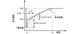
- Explanatory drawing which shows the mode of the change of voltage command value V *.
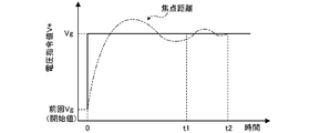
- Explanatory drawing which shows the mode of the change of the focal distance in the conventional drive control.
- the flowchart which shows an example of the drive control processing of a modification.
- Explanatory drawing which shows the relationship between voltage command amount (DELTA) V * output multiple times, and the voltage which the drive part 24 applies to the liquid lens 20.
- DELTA voltage command amount
- FIG. 1 is a configuration diagram showing an outline of a configuration of an imaging apparatus 10 according to an embodiment of the present invention.
- the imaging apparatus 10 of the present embodiment controls the liquid lens 20 as a variable focus lens capable of adjusting the focal length (focal position), the drive unit 24 that drives the liquid lens 20, and the drive unit 24.
- Drive control unit 26 an image sensor 30 that photoelectrically converts light incident through the liquid lens 20 to generate an electrical signal, and a signal that generates image data by inputting the electrical signal generated by the image sensor 30
- a processing unit 32 a storage unit 34 capable of storing the image data generated by the signal processing unit 32; and a detection unit 36 that detects a focal length at which a subject is in focus based on the generated image data.
- a control unit 40 that controls the entire imaging apparatus.
- the imaging device 10 can be applied to a digital camera that captures an image based on an operation of a shutter button, a camera mounted on a robot, a stationary camera, or the like.
- the liquid lens 20 includes an aqueous solution, oil, and electrodes 22a and 22b sealed.
- the liquid lens 20 applies a voltage between the electrodes 22a and 22b to deform the boundary surface between the aqueous solution and oil. ) Can be adjusted.
- the drive unit 24 includes a variable voltage power supply circuit that makes the applied voltage variable.
- the drive unit 24 applies a voltage corresponding to the voltage command value V * between the electrodes 22a and 22b by controlling the variable voltage power supply circuit based on the voltage command value V * from the drive control unit 26, The focal length (focal position) of the liquid lens 20 is adjusted.
- the drive control unit 26 drives and controls the liquid lens 20 by outputting a drive command value (voltage command value V *) to the drive unit 24 based on an instruction from the control unit 40.
- the image sensor 30 is an image sensor that converts an image of a subject into an electric signal by photoelectric conversion.
- a CMOS or a CCD is used.
- the signal processing unit 32 generates image data by performing signal processing such as sampling processing, development processing, and YC separation processing on the electrical signal input from the image sensor 30.
- the signal processing unit 32 stores the generated image data in the storage unit 34 or outputs it to the detection unit 36.
- the detection unit 36 captures an image with the highest contrast among the images of the object captured through the liquid lens 20 while changing the voltage applied to the liquid lens 20 (electrodes 22a and 22b) stepwise.
- the state of the liquid lens 20 (in-focus state) is estimated, and an applied voltage (focusing voltage Vfc) necessary for obtaining the in-focus state of the liquid lens 20 is derived.
- the control unit 40 controls each unit of the imaging apparatus 10. Specifically, when an imaging instruction is input, the control unit 40 performs a focusing process for automatically focusing on the target, and then performs an imaging process so as to capture the target. In the focusing process, the control unit 40 outputs a focusing control command to the detecting unit 36 so as to execute the focusing detection process. In the imaging process, the control unit 40 outputs an imaging control command to the imaging element 30, the signal processing unit 32, and the storage unit 34 so as to image the target object. Further, the control unit 40 outputs a drive control command to the drive control unit 26 so as to perform drive control of the liquid lens 20 as necessary, for example, when performing a focusing process.
- FIG. 2 is a flowchart illustrating an example of a drive control process executed by the drive control unit 26.
- FIG. 3 is an explanatory diagram showing how the voltage command value V * changes. The drive control process is executed when the drive control unit 26 inputs a drive control command from the control unit 40.
- the drive control unit 26 When the drive control process is executed, the drive control unit 26 first sets a target command value Vg (step S100).
- the target command value Vg is a voltage command value V * for deforming the liquid lens 20 to the target value of the focal length in the current drive control process.
- the drive control unit 26 sets the target command value Vg based on the target command value Vg included in the drive control command from the control unit 40 or the target value of the focal length.
- the drive control unit 26 sets the voltage command value V * by adding the initial change amount ⁇ Vini to the previous target command value Vg, that is, the start value of the voltage command value V * (step S110). In step S110, as shown in FIG.
- the drive control unit 26 sets the initial voltage Vini, which is the sum of the previous target command value Vg and the initial change amount ⁇ Vini, to the voltage command value V *.
- the “previous target command value Vg” (start value) is, in other words, the voltage command value V * last output to the drive unit 24 in the most recent (previous) drive control process.
- the voltage command value V * corresponds to the focal length of the liquid lens 20 at the start. For example, when the previous drive control process is not performed, such as when this is the first drive control process after the imaging apparatus 10 is powered on, the “previous target command value Vg” (start value) may be 0. .
- the initial change amount ⁇ Vini is a value obtained by multiplying the target change amount ⁇ Vg, which is the change amount of the voltage command value V * up to the target command value Vg in the current drive control process, by the first ratio R1. .
- the target change amount ⁇ Vg is the difference between the target command value Vg and the previous target command value Vg (start value) in the current drive control process.
- 1st ratio R1 can be suitably set within the range of 0% excess and 100% or less.
- the first ratio R1 may be a value of 20% or more, or a value of 70% or less.
- the first ratio R1 may be a value of 50% or less.
- the drive control unit 26 outputs the set voltage command value V * to the drive unit 24 (step S120).
- the drive unit 24 to which the voltage command value V * is input controls the variable voltage power supply circuit so that a voltage corresponding to the voltage command value V * is applied between the electrodes 22a and 22b of the liquid lens 20.
- the drive control unit 26 determines whether or not the output voltage command value V * is greater than or equal to the target command value Vg, that is, whether or not the target command value Vg has been reached (step S130). If it is determined that the voltage command value V * has not reached the target command value Vg, the drive control unit 26 updates the voltage command value V * by adding the amount of change ⁇ V to the current voltage command value V * (step). S140).
- the change amount ⁇ V is a value obtained by multiplying the target change amount ⁇ Vg by the second ratio R2.
- the second ratio R2 can be set as appropriate within the range of more than 0% and less than 100%, but in the present embodiment, the second ratio R2 is set to a value smaller than the first ratio R1.
- the change amount ⁇ V is set to a value smaller than the initial change amount ⁇ Vini.
- the second ratio R2 may be a value of 5% or more, for example, or a value of 30% or less.
- the second ratio R2 may be a value of 20% or less or a value of around 10%.
- the response time of the liquid lens 20 is the time from when the voltage from the driving unit 24 is applied between the electrodes 22a and 22b until the deformation of the boundary surface of the liquid lens 20 is completed. More specifically, the response time is the time until the focal length of the liquid lens 20 is stabilized at a value corresponding to the applied voltage (until the focal length converges within ⁇ 5% of the stabilized value). To do. If the drive control unit 26 determines in step S130 that the voltage command value V * has reached the target command value Vg, the drive control process ends.
- the drive control unit 26 changes the voltage command value V * to the initial voltage Vini at once (changes by the initial change amount ⁇ Vini) and then toward the target command value Vg.
- the amount of change is changed by ⁇ V every predetermined time ⁇ T.
- the drive control unit 26 sets the target command value Vg from the beginning as the voltage command value V * and outputs it to the drive unit 24, the focal length causes overshoot or hunting.
- the time t1 in FIG. It becomes shorter than the time t2 in FIG.
- the liquid lens 20 can be quickly started up. Therefore, the liquid lens 20 can be controlled at a higher speed.
- the initial change amount ⁇ Vini or the first ratio R1 can be set as appropriate within a range in which the focal length overshoot does not become excessive.
- the drive control unit 26 indicates that the drive control is completed, that is, the focal length of the liquid lens 20 is represented by the target command value Vg after the predetermined time Ta has elapsed since the voltage command value V * was last output (step S120).
- a signal indicating that the value has converged to the value may be output to the control unit 40.
- the predetermined time Ta can be determined as, for example, the same value as the response time of the liquid lens 20 or a value obtained by adding a margin to the response time.
- the control unit 40 outputs a focusing control command to the detection unit 36, and drives and controls the liquid lens 20 with the minimum value (for example, value 0) of the voltage command value V * as the target command value Vg.
- a drive control command is output to the drive control unit 26.
- the control unit 40 issues a drive control command to the drive control unit 26 so as to drive and control the liquid lens 20 with the maximum value of the voltage command value V * as the target command value Vg. Output.
- the detection unit 36 that has received the focus control command measures the elapsed time from the start of the drive control process in which the maximum value of the voltage command value V * is set as the target command value Vg. In addition, the detection unit 36 acquires a captured image captured through the liquid lens 20 from the signal processing unit 32 until the drive control is completed, and performs detection based on the acquired captured image (luminance information). The contrast evaluation value of the object is repeatedly calculated, and the contrast evaluation value and the elapsed time are associated with each other and stored in the storage unit 34. Then, the detection unit 36 extracts the elapsed time associated with the maximum value of the calculated contrast evaluation values as the maximum value detection time, and the voltage command value V that allows focusing based on the maximum value detection time.
- the focusing voltage Vfc is derived.
- the derivation of the focusing voltage Vfc based on the maximum value detection time by the detection unit 36 can be performed based on, for example, a table in which the two are associated in advance, a conversion formula, or the like stored in advance in the storage unit 34.
- the control unit 40 outputs a drive control command to the drive control unit 26 so as to drive and control the liquid lens 20 with the derived focusing voltage Vfc as the target command value Vg.
- the focal length of the liquid lens 20 is adjusted to a value that allows focusing.
- the control unit 40 performs an imaging process so as to image the object.
- the drive control unit 26 performs drive control of the liquid lens 20 based on the drive control command from the control unit 40.
- the liquid lens 20 can be controlled at a higher speed as described above, so that the focusing process can also be performed at a high speed.
- the liquid lens 20 of the present embodiment corresponds to a variable focus lens of the present invention
- the drive unit 24 corresponds to a drive unit
- the drive control unit 26 corresponds to a drive control unit.
- the drive control unit 26 is shorter than the response time of the liquid lens 20 with respect to the drive unit 24 that drives the liquid lens 20 according to the voltage command value V *.
- a voltage command value V * that is changed stepwise at intervals is output.
- the drive control unit 26 changes the voltage command value V * output to the drive unit 24 stepwise to the target command value Vg, the focal length of the liquid lens 20 is increased to a value represented by the target command value Vg. It can be controlled at high speed.
- the change amount (initial change amount ⁇ Vini, change amount ⁇ V) of the voltage command value V * at each stage reaches the target command value Vg.
- the voltage command value V * of each stage is set to a predetermined ratio (first ratio R1, second ratio R2) with respect to the total change amount (target change amount ⁇ Vg).
- the change amount of the voltage command value V * at each stage is a constant amount regardless of the target change amount ⁇ Vg
- the target change amount ⁇ Vg when the target change amount ⁇ Vg is very large, the number of steps of the voltage command value V * is too large.
- the target command value Vg may not be reached easily, and the time required for the drive control processing of the liquid lens 20 may become long.
- the target change amount ⁇ Vg is very small, there are cases where the number of steps of the change in the voltage command value V * is so small that the focal length overshoot and hunting are not sufficiently suppressed.
- the drive control unit 26 changes the voltage command value V * output to the drive unit 24 to a predetermined value (initial voltage Vini) at a time, and then changes the voltage command value V * stepwise. Thereby, the rise of driving of the liquid lens 20 can be quickly performed while suppressing overshoot and hunting of the focal length, and the liquid lens 20 can be controlled at higher speed.
- the imaging device 10 also includes a liquid lens 20 as a variable focus lens. Since the liquid lens 20 may cause overshoot or hunting when the focal length is changed and the response time becomes long, the significance of applying the present invention is high.
- the drive control unit 26 outputs the voltage command value V * representing the voltage to be applied to the liquid lens 20 to the drive unit 24, and the output voltage command value V * is stepwise.
- the drive control unit 26 may output a voltage command amount ⁇ V * (drive command amount) representing the amount of change in voltage to be applied to the liquid lens 20 to the drive unit 24 a plurality of times.
- the voltage command amount ⁇ V * is a value corresponding to the change amount of the voltage command value V * at each stage in the above-described embodiment.
- FIG. 5 is a flowchart illustrating an example of a drive control process according to a modified example in this case.
- step S200 the drive control unit 26 sets the target change amount ⁇ Vg based on the value of the target change amount ⁇ Vg input from the control unit 40, for example.
- the drive control unit 26 receives the target command value Vg in the current drive control process from the control unit 40 as in the above-described embodiment, and calculates the input value and the previous target command value Vg (start value).
- the target change amount ⁇ Vg may be derived based on the difference.
- the drive control unit 26 sets the initial change amount ⁇ Vini to the voltage command amount ⁇ V * (step S210), and outputs the set voltage command amount ⁇ V * to the drive unit 24 (step S220).
- the initial change amount ⁇ Vini may be a value obtained by multiplying the target change amount ⁇ Vg by the first ratio R1 as in the above-described embodiment.
- the drive unit 24 that has received the voltage command amount ⁇ V * controls the variable voltage power supply circuit so that the current applied voltage to the liquid lens 20 changes by the voltage command amount ⁇ V *.
- the drive control unit 26 determines whether or not the total value of the voltage command amount ⁇ V * output in the current drive control process is equal to or greater than the target change amount ⁇ Vg, that is, whether or not the target change amount ⁇ Vg has been reached. (Step S230). If it is determined that the total value of the voltage command amount ⁇ V * has not reached the target change amount ⁇ Vg, the drive control unit 26 sets the change amount ⁇ V to the voltage command amount ⁇ V * and updates the voltage command amount ⁇ V * ( Step S240).
- the change amount ⁇ V may be a value obtained by multiplying the target change amount ⁇ Vg by the second ratio R2 as in the above-described embodiment.
- step S250 the drive control unit 26 returns to step S220 and transfers the updated voltage command amount ⁇ V * to the drive unit. 24. If the drive control unit 26 determines in step S230 that the total value of the voltage command amount ⁇ V * has reached the target change amount ⁇ Vg, the drive control unit 26 ends the drive control process. Thus, even when the drive control unit 26 outputs the voltage command amount ⁇ V * to the drive unit 24 instead of the voltage command value V *, the same effect as that of the above-described embodiment can be obtained.
- the drive control unit 26 outputs the voltage command amount ⁇ V * a plurality of times until the total value of the voltage command amounts ⁇ V * output to the drive unit 24 reaches the target change amount ⁇ Vg, so that the focal length of the liquid lens 20 is increased. It can be changed at high speed by the distance corresponding to the target change amount ⁇ Vg.
- the voltage command amount ⁇ V * at each stage is changed according to the magnitude of the target change amount ⁇ Vg by making each of the voltage command amounts ⁇ V * of the plurality of times become a predetermined ratio amount with respect to the target change amount ⁇ Vg.
- the rise of driving of the liquid lens 20 can be quickly performed while suppressing overshoot and hunting of the focal length, and the liquid lens 20 can be controlled at higher speed.
- the modification of the above-described embodiment described below can be similarly applied to the mode in which the drive control unit 26 described in FIGS. 5 and 6 outputs the voltage command amount ⁇ V *.
- the voltage command value V * output to the drive unit 24 is changed to the predetermined value (initial voltage Vini) at once, and then the voltage command value V * is changed stepwise. I can't.
- the voltage command value V * may always be changed stepwise by the same amount of change ⁇ V, for example, the first ratio R1 and the second ratio R2 are set to the same value.
- the amount of change in the voltage command value V * is two types, that is, the initial change amount ⁇ Vini and the amount of change ⁇ V. There may be more than two types.
- the change amount of the voltage command value V * at each stage is the total value of the change amounts of the voltage command value V * at each stage up to the target command value Vg.
- the amount is set to a predetermined ratio (first ratio R1, second ratio R2) with respect to (target change amount ⁇ Vg), it is not limited thereto.
- the change amount of the voltage command value V * at each stage may be determined in advance regardless of the value of the target change amount ⁇ Vg.
- the drive control unit 26 changes the voltage command value V * output to the drive unit 24 step by step to the target command value Vg, but is not limited thereto. For example, even if the drive control unit 26 continuously performs the process of changing the voltage command value V * in steps (for example, steps S120, S140, and S150 in FIG. 2) until a stop signal is input from the control unit 40. Good.
- the time interval (predetermined time ⁇ T) of the change in each step of the voltage command value V * is constant, but the time interval may be shorter than the response time of the liquid lens 20 or may not be constant.
- the drive control unit 26 sets the time interval so that the time interval until the next stage becomes larger as the amount of change increases. Good. That is, in step S150, the drive control unit 26 sets the value of the predetermined time ⁇ T so that the predetermined time ⁇ T tends to increase as the value of the voltage command value V * output in the previous step S120 increases. It may be set.
- the present invention can be used in the manufacturing industry of imaging devices such as digital cameras that capture images based on shutter button operations, cameras mounted on robots, and stationary cameras.
- imaging device 20 liquid lens, 22a, 22b electrode, 24 drive unit, 26 drive control unit, 30 image sensor, 32 signal processing unit, 34 storage unit, 36 detection unit, 40 control unit.
Landscapes
- Physics & Mathematics (AREA)
- General Physics & Mathematics (AREA)
- Optics & Photonics (AREA)
- Lens Barrels (AREA)
Abstract
撮像装置において、駆動制御部は、電圧指令値V*に従って液体レンズを駆動する駆動部に対して、液体レンズの応答時間よりも短い時間間隔(ΔT)で段階的に変化させた電圧指令値V*を出力する。駆動制御部は、駆動部に出力する電圧指令値V*を目標指令値Vgまで段階的に変化させてもよい。駆動制御部は、電圧指令値V*を段階的に変化させるにあたり、各段での電圧指令値V*の変化量(初期変化量ΔVini,変化量ΔV)が、目標指令値Vgまでの各段の電圧指令値V*の変化量の合計値(目標変化量ΔVg)に対する所定割合の量になるようにしてもよい。
Description
本発明は、撮像装置に関する。
従来、撮像装置としては、焦点距離を変更可能な液体レンズなどの可変焦点レンズを備えたものが知られている。例えば、特許文献1には、撮像対象物までの距離情報と液体レンズに印加すべき電圧情報との関係を表すテーブルに基づき、撮像対象物までの距離に応じた電圧を液体レンズに印加して、撮像対象物への合焦を行うことが記載されている。
ところで、このような可変焦点レンズでは、指令(例えば印加電圧)が入力されてから実際に焦点距離の変化が完了するまでの間に、焦点距離のオーバーシュートやハンチングなどが生じて応答時間が長くなる場合があった。このため、例えば画像を撮像する前の待ち時間が長くなる場合があった。
本発明はこのような課題を解決するためになされたものであり、可変焦点レンズをより高速に制御することを主目的とする。
本発明は、上述した主目的を達成するために以下の手段を採った。
本発明の第1の撮像装置は、
可変焦点レンズと、
駆動指令値に従って前記可変焦点レンズを駆動する駆動部と、
前記駆動部に対して、前記可変焦点レンズの応答時間よりも短い時間間隔で段階的に変化させた前記駆動指令値を出力する駆動制御部と、
を備えたものである。
可変焦点レンズと、
駆動指令値に従って前記可変焦点レンズを駆動する駆動部と、
前記駆動部に対して、前記可変焦点レンズの応答時間よりも短い時間間隔で段階的に変化させた前記駆動指令値を出力する駆動制御部と、
を備えたものである。
本発明の第2の撮像装置は、
可変焦点レンズと、
駆動指令量に従って前記可変焦点レンズを駆動する駆動部と、
前記駆動部に対して、前記可変焦点レンズの応答時間よりも短い時間間隔で前記駆動指令量を複数回出力する駆動制御部と、
を備えたものである。
可変焦点レンズと、
駆動指令量に従って前記可変焦点レンズを駆動する駆動部と、
前記駆動部に対して、前記可変焦点レンズの応答時間よりも短い時間間隔で前記駆動指令量を複数回出力する駆動制御部と、
を備えたものである。
この第1の撮像装置では、駆動指令値に従って前記可変焦点レンズを駆動する駆動部に対して、可変焦点レンズの応答時間よりも短い時間間隔で段階的に変化させた駆動指令値を出力する。このように、可変焦点レンズの焦点距離の変化が完了するのを待たずに次々に駆動指令値を変化させていくことで、焦点距離のオーバーシュートやハンチングを抑制して、結果的に焦点距離をより高速に変化させることができる。すなわち、可変焦点レンズをより高速に制御できる。また、この第2の撮像装置では、駆動指令値に従って前記可変焦点レンズを駆動する駆動部に対して、前記可変焦点レンズの応答時間よりも短い時間間隔で前記駆動指令量を複数回出力する。この第2の撮像装置でも、可変焦点レンズの焦点距離の変化が完了するのを待たずに次々に駆動指令量を出力することで、焦点距離のオーバーシュートやハンチングを抑制して、結果的に焦点距離をより高速に変化させることができる。すなわち、可変焦点レンズをより高速に制御できる。
ここで、「可変焦点レンズ」には、レンズを移動させることで焦点距離を調整可能なものや、レンズを変形させることにより焦点距離を調整可能なもの(例えば、液体レンズ)が含まれる。また、前者の場合、「駆動部」として、モータの他、導電性高分子アクチュエータなどのアクチュエータ素子も含まれる。
図1は本発明の一実施形態である撮像装置10の構成の概略を示す構成図である。本実施形態の撮像装置10は、図示するように、焦点距離(焦点位置)を調整可能な可変焦点レンズとしての液体レンズ20と、液体レンズ20を駆動する駆動部24と、駆動部24を制御する駆動制御部26と、液体レンズ20を介して入射した光を光電変換して電気信号を生成する撮像素子30と、撮像素子30で生成された電気信号を入力して画像データを生成する信号処理部32と、信号処理部32で生成された画像データを記憶可能な記憶部34と、生成された画像データに基づいて被写体に対して合焦が得られる焦点距離を検出する検出部36と、撮像装置全体を制御する制御部40と、を備える。なお、撮像装置10は、シャッターボタンの操作に基づいて撮像するデジタルカメラや、ロボットに搭載されるカメラ、据え置き型のカメラ等に適用可能である。
液体レンズ20は、水溶液と油と電極22a,22bとが封入されており、電極22a,22b間に電圧を印加して、水溶液と油との境界面を変形させることにより、焦点距離(焦点位置)を調整可能な可変焦点レンズである。
駆動部24は、印加電圧を可変とする可変電圧電源回路を備える。この駆動部24は、駆動制御部26からの電圧指令値V*に基づいて可変電圧電源回路を制御することにより、電極22a,22b間に電圧指令値V*に応じた電圧を印加して、液体レンズ20の焦点距離(焦点位置)を調整する。
駆動制御部26は、制御部40からの指示に基づいて、駆動部24に対して駆動指令値(電圧指令値V*)を出力することにより液体レンズ20を駆動制御する。
撮像素子30は、被写体の像を光電変換によって電気信号に変換するイメージセンサであり、例えば、CMOSやCCDなどが用いられる。
信号処理部32は、撮像素子30から入力される電気信号に対して、サンプリング処理や現像処理、YC分離処理などの信号処理を施すことで画像データを生成する。信号処理部32は、画像データを生成すると、生成した画像データを記憶部34に記憶したり、検出部36に出力したりする。
検出部36は、液体レンズ20(電極22a,22b)への印加電圧を段階的に変化させながら液体レンズ20を介して撮像される対象物の画像のうちコントラストが最も高い画像が撮像されたときの液体レンズ20の状態(合焦状態)を推定し、液体レンズ20の合焦状態を得るために必要な印加電圧(合焦電圧Vfc)を導出する。
制御部40は、撮像装置10の各部を制御するものである。具体的には、撮像指示が入力されると、制御部40は、対象物に対して焦点を自動で合わせる合焦処理を行い、その後に対象物を撮像するよう撮像処理を行う。合焦処理では、制御部40は、合焦検出処理を実行するよう合焦制御指令を検出部36に出力する。撮像処理では、制御部40は、対象物を撮像するよう撮像制御指令を撮像素子30,信号処理部32,及び記憶部34に出力する。また、制御部40は、例えば合焦処理を行う際など必要に応じて、液体レンズ20の駆動制御を行うよう駆動制御指令を駆動制御部26に出力する。
次に、こうして構成された本実施形態の撮像装置10の動作、特に、液体レンズ20の駆動制御を行う際の動作について説明する。図2は、駆動制御部26により実行される駆動制御処理の一例を示すフローチャートである。図3は、電圧指令値V*の変化の様子を示す説明図である。駆動制御処理は、駆動制御部26が制御部40から駆動制御指令を入力したときに実行される。
駆動制御処理が実行されると、駆動制御部26は、まず、目標指令値Vgを設定する(ステップS100)。目標指令値Vgは、今回の駆動制御処理における焦点距離の目標値に液体レンズ20を変形させるための電圧指令値V*である。駆動制御部26は、例えば制御部40からの駆動制御指令に含まれる目標指令値Vgの値又は焦点距離の目標値に基づいて、目標指令値Vgを設定する。続いて、駆動制御部26は、前回の目標指令値Vgすなわち電圧指令値V*の開始値に初期変化量ΔViniを加算することにより電圧指令値V*を設定する(ステップS110)。ステップS110では、図3に示すように、駆動制御部26は前回の目標指令値Vgと初期変化量ΔViniとの和である初期電圧Viniを電圧指令値V*に設定する。なお、「前回の目標指令値Vg」(開始値)は、換言すると、直近(前回)の駆動制御処理において最後に駆動部24に出力した電圧指令値V*であり、今回の駆動制御処理の開始時での液体レンズ20の焦点距離に対応する電圧指令値V*である。例えば今回が撮像装置10の電源オン後の最初の駆動制御処理である場合など、前回の駆動制御処理がない場合には、「前回の目標指令値Vg」(開始値)は値0としてもよい。また、本実施形態では、初期変化量ΔViniは、今回の駆動制御処理における目標指令値Vgまでの電圧指令値V*の変化量である目標変化量ΔVgに第1割合R1を乗じた値とした。図3に示すように、目標変化量ΔVgは、今回の駆動制御処理における目標指令値Vgと前回の目標指令値Vg(開始値)との差である。なお、第1割合R1は、0%超過100%以下の範囲内で適宜設定することができる。例えば、第1割合R1は20%以上の値としてもよいし、70%以下の値としてもよい。第1割合R1は、50%以下の値としてもよい。ステップS110のあと、駆動制御部26は、設定した電圧指令値V*を駆動部24に出力する(ステップS120)。電圧指令値V*を入力した駆動部24は、電圧指令値V*に応じた電圧が液体レンズ20の電極22a,22b間に印加されるよう可変電圧電源回路を制御する。
続いて、駆動制御部26は、出力した電圧指令値V*が目標指令値Vg以上であるか否かすなわち目標指令値Vgに達したか否かを判定する(ステップS130)。電圧指令値V*が目標指令値Vgに達していないと判定すると、駆動制御部26は、現在の電圧指令値V*に変化量ΔVを加算することにより電圧指令値V*を更新する(ステップS140)。本実施形態では、変化量ΔVは、目標変化量ΔVgに第2割合R2を乗じた値とした。なお、第2割合R2は、0%超過100%未満の範囲内で適宜設定することができるが、本実施形態では、第1割合R1よりも小さい値とした。すなわち、変化量ΔVは、初期変化量ΔViniより小さい値とした。第2割合R2は、例えば5%以上の値としてもよいし、30%以下の値としてもよい。第2割合R2は、20%以下の値としてもよいし、10%前後の値としてもよい。そして、駆動制御部26は、前回の電圧指令値V*の出力から所定時間ΔTが経過するのを待ってから(ステップS150)、ステップS120に戻って、更新した電圧指令値V*を駆動部24に出力する。ここで、所定時間ΔTは、液体レンズ20の応答時間(10~20msec)よりも短い時間であり、数msec程度とすることができる。なお、液体レンズ20の応答時間は、駆動部24からの電圧が電極22a,22b間に印加されてから、液体レンズ20の境界面の変形が完了するまでの時間である。より具体的には、応答時間は、液体レンズ20の焦点距離が印加された電圧に応じた値で安定するまで(焦点距離が安定後の値の±5%以内に収束するまで)の時間とする。そして、駆動制御部26は、ステップS130で電圧指令値V*が目標指令値Vgに達したと判定すると、駆動制御処理を終了する。
この駆動制御処理では、図3に示すように、駆動制御部26は電圧指令値V*を初期電圧Viniまで一度に変化(初期変化量ΔViniだけ変化)させた後、目標指令値Vgに向けて所定時間ΔT毎に変化量ΔVずつ変化させる。このように、液体レンズ20の応答時間よりも短い時間間隔で電圧指令値V*を次々に変化させることで、焦点距離のオーバーシュートやハンチングを抑制して、迅速且つスムーズに液体レンズ20を変形させることができる。これに対し、例えば図4に示すように、駆動制御部26が電圧指令値V*として最初から目標指令値Vgを設定して駆動部24に出力する場合、焦点距離はオーバーシュートやハンチングが生じてから目標指令値Vgに対応する値に収束する。そのため、図3,図4において駆動制御処理の開始から液体レンズ20の焦点距離が目標指令値Vgに応じた値で安定するまでの時間t1,t2を比較すると、図3における時間t1の方が図4における時間t2よりも短くなる。なお、本実施形態では、電圧指令値V*を初期電圧Viniまで一度に変化させた後、変化量ΔVずつ段階的に変化させるため、液体レンズ20の駆動の立ち上がりを素早くすることができる。そのため、液体レンズ20をより高速に制御することができる。なお、初期変化量ΔVini又は第1割合R1は、焦点距離のオーバーシュートが過大とならない範囲内で適宜設定することができる。
なお、駆動制御部26は、最後に電圧指令値V*を出力(ステップS120)してから所定時間Ta経過後に、駆動制御が完了した旨すなわち液体レンズ20の焦点距離が目標指令値Vgで表される値に収束した旨の信号を制御部40に出力してもよい。所定時間Taは、例えば液体レンズ20の応答時間と同じ値又は応答時間にマージンを持たせた値として定めることができる。
次に、制御部40が行う合焦処理の一例について説明する。合焦処理では、制御部40は、合焦制御指令を検出部36に出力すると共に、電圧指令値V*の最小値(例えば値0)を目標指令値Vgとして液体レンズ20を駆動制御するよう駆動制御部26に駆動制御指令を出力する。続いて、液体レンズ20の駆動制御処理の完了後に、制御部40は、電圧指令値V*の最大値を目標指令値Vgとして液体レンズ20を駆動制御するよう駆動制御部26に駆動制御指令を出力する。合焦制御指令を入力した検出部36は、電圧指令値V*の最大値を目標指令値Vgとする駆動制御処理の開始からの経過時間を測定する。また、検出部36は、この駆動制御が完了するまでの間に、液体レンズ20を介して撮像された撮像画像を信号処理部32から取得し、取得した撮像画像(輝度情報)に基づいて対象物のコントラスト評価値を繰り返し算出して、コントラスト評価値と経過時間とを対応づけて記憶部34に記憶する。そして、検出部36は、算出したコントラスト評価値のうちの最大値に対応づけられた経過時間を最大値検出時間として抽出し、この最大値検出時間に基づいて合焦が得られる電圧指令値V*すなわち合焦電圧Vfcを導出する。なお、検出部36による最大値検出時間に基づく合焦電圧Vfcの導出は、例えば予め両者を対応づけたテーブルや換算式などを記憶部34に記憶しておき、これに基づいて行うことができる。そして、制御部40は、導出された合焦電圧Vfcを目標指令値Vgとして液体レンズ20を駆動制御するよう駆動制御部26に駆動制御指令を出力する。これにより、液体レンズ20の焦点距離は合焦が得られる値に調整される。その後、制御部40は、対象物を撮像するよう撮像処理を行う。このように、合焦処理では、駆動制御部26は制御部40からの駆動制御指令に基づいて液体レンズ20の駆動制御を行う。そして、本実施形態の駆動制御処理では上述したように液体レンズ20をより高速に制御できるため、合焦処理も高速に行うことができる。
ここで、本実施形態の構成要素と本発明の構成要素との対応関係を明らかにする。本実施形態の液体レンズ20が本発明の可変焦点レンズに相当し、駆動部24が駆動部に相当し、駆動制御部26が駆動制御部に相当する。
以上詳述した本実施形態の撮像装置10によれば、駆動制御部26は、電圧指令値V*に従って液体レンズ20を駆動する駆動部24に対して、液体レンズ20の応答時間よりも短い時間間隔で段階的に変化させた電圧指令値V*を出力する。このように、液体レンズ20の焦点距離の変化が完了するのを待たずに次々に駆動指令値を変化させていくことで、焦点距離のオーバーシュートやハンチングを抑制して、結果的に焦点距離をより高速に変化させることができる。すなわち、液体レンズ20をより高速に制御できる。
また、駆動制御部26は、駆動部24に出力する電圧指令値V*を目標指令値Vgまで段階的に変化させるため、液体レンズ20の焦点距離を目標指令値Vgで表される値までより高速に制御できる。
また、駆動制御部26は、電圧指令値V*を段階的に変化させるにあたり、各段での電圧指令値V*の変化量(初期変化量ΔVini,変化量ΔV)が、目標指令値Vgまでの各段の電圧指令値V*の変化量の合計値(目標変化量ΔVg)に対する所定割合(第1割合R1,第2割合R2)の量になるようにする。これにより、目標変化量ΔVgの大小に応じて各段での電圧指令値V*の変化量を変更して、焦点距離のオーバーシュートやハンチングを適切に抑制できる。例えば、各段での電圧指令値V*の変化量が目標変化量ΔVgに無関係に一定量であった場合、目標変化量ΔVgが非常に大きいときには電圧指令値V*の変化の段数が多すぎて目標指令値Vgになかなか到達せず、液体レンズ20の駆動制御処理に必要な時間が長くなる場合がある。また、目標変化量ΔVgが非常に小さいときには、電圧指令値V*の変化の段数が少なすぎて焦点距離のオーバーシュートやハンチングの抑制が不十分になる場合がある。各段での電圧指令値V*の変化量を目標変化量ΔVgの所定割合の量とすることで、これらを抑制できる。
また、駆動制御部26は、駆動部24に出力する電圧指令値V*を所定値(初期電圧Vini)まで一度に変化させた後、電圧指令値V*を段階的に変化させる。これにより、焦点距離のオーバーシュートやハンチングを抑制しつつ液体レンズ20の駆動の立ち上がりを素早くすることができ、液体レンズ20をより高速に制御することができる。
また、撮像装置10は、可変焦点レンズとしての液体レンズ20を備えている。液体レンズ20は焦点距離が変化する際にオーバーシュートやハンチングが生じて応答時間が長くなる場合があるため、本発明を適用する意義が高い。
なお、本発明は上述した実施形態に何ら限定されることはなく、本発明の技術的範囲に属する限り種々の態様で実施し得ることはいうまでもない。
例えば、上述した実施形態では、駆動制御部26は、駆動部24に対して、液体レンズ20に印加すべき電圧を表す電圧指令値V*を出力し、出力する電圧指令値V*を段階的に変化させたが、これに限られない。駆動制御部26は、駆動部24に対して、液体レンズ20に印加すべき電圧の変化量を表す電圧指令量ΔV*(駆動指令量)を複数回出力してもよい。電圧指令量ΔV*は、上述した実施形態における各段の電圧指令値V*の変化量に相当する値である。図5は、この場合の変形例の駆動制御処理の一例を示すフローチャートである。図6は、複数回出力される電圧指令量ΔV*と駆動部24が液体レンズ20に印加する電圧との関係を示す説明図である。図5の駆動制御処理が実行されると、駆動制御部26は、まず、目標変化量ΔVgを設定する(ステップS200)。駆動制御部26は、例えば制御部40から入力した目標変化量ΔVgの値に基づいて目標変化量ΔVgを設定する。なお、駆動制御部26は、上述した実施形態と同様に、今回の駆動制御処理における目標指令値Vgを制御部40から入力し、入力した値と前回の目標指令値Vg(開始値)との差に基づいて目標変化量ΔVgを導出してもよい。続いて、駆動制御部26は、初期変化量ΔViniを電圧指令量ΔV*に設定し(ステップS210)、設定した電圧指令量ΔV*を駆動部24に出力する(ステップS220)。初期変化量ΔViniは、上述した実施形態と同様に、目標変化量ΔVgに第1割合R1を乗じた値としてもよい。電圧指令量ΔV*を入力した駆動部24は、現在の液体レンズ20への印加電圧が電圧指令量ΔV*だけ変化するよう可変電圧電源回路を制御する。次に、駆動制御部26は、今回の駆動制御処理で出力した電圧指令量ΔV*の合計値が目標変化量ΔVg以上であるか否かすなわち目標変化量ΔVgに達したか否かを判定する(ステップS230)。電圧指令量ΔV*の合計値が目標変化量ΔVgに達していないと判定すると、駆動制御部26は、変化量ΔVを電圧指令量ΔV*に設定して、電圧指令量ΔV*を更新する(ステップS240)。変化量ΔVは、上述した実施形態と同様に、目標変化量ΔVgに第2割合R2を乗じた値としてもよい。そして、駆動制御部26は、前回の電圧指令量ΔV*の出力から所定時間ΔTが経過するのを待ってから(ステップS250)、ステップS220に戻って、更新した電圧指令量ΔV*を駆動部24に出力する。そして、駆動制御部26は、ステップS230で電圧指令量ΔV*の合計値が目標変化量ΔVgに達したと判定すると、駆動制御処理を終了する。このように、駆動制御部26が駆動部24に対して電圧指令値V*の代わりに電圧指令量ΔV*を出力する場合でも、上述した実施形態と同様の効果が得られる。例えば、液体レンズ20の応答時間よりも短い時間間隔で電圧指令量ΔV*を複数回出力するため、焦点距離のオーバーシュートやハンチングを抑制して、液体レンズ20をより高速に制御できる。また、駆動制御部26が、駆動部24に出力した電圧指令量ΔV*の合計値が目標変化量ΔVgに達するまで電圧指令量ΔV*を複数回出力することで、液体レンズ20の焦点距離を目標変化量ΔVgに応じた距離の分だけ高速に変化させることができる。また、複数回の電圧指令量ΔV*の各々が目標変化量ΔVgに対する所定割合の量になるようにすることで、目標変化量ΔVgの大小に応じて各段での電圧指令量ΔV*を変更して、焦点距離のオーバーシュートやハンチングを適切に抑制できる。また、駆動制御部26は、駆動部24に対して、所定量の電圧指令量ΔV*(=初期変化量ΔVini)を出力した後、初期変化量ΔViniよりも小さい電圧指令量ΔV*(=変化量ΔV)を複数回出力することで、焦点距離のオーバーシュートやハンチングを抑制しつつ液体レンズ20の駆動の立ち上がりを素早くすることができ、液体レンズ20をより高速に制御することができる。なお、以下に説明する上述した実施形態の変形例は、図5,6で説明した駆動制御部26が電圧指令量ΔV*を出力する態様に対しても、同様に適用することができる。
上述した実施形態では、駆動部24に出力する電圧指令値V*を所定値(初期電圧Vini)まで一度に変化させた後、電圧指令値V*を段階的に変化させたが、これに限られない。例えば、第1割合R1と第2割合R2とを同じ値にするなど、電圧指令値V*を常に同じ変化量ΔVずつ段階的に変化させてもよい。また、上述した実施形態では、電圧指令値V*の変化量は初期変化量ΔViniと変化量ΔVとの2種類であったが、特にこれに限らず、各段の電圧指令値V*の変化量が3種類以上存在してもよい。
上述した実施形態では、各段での電圧指令値V*の変化量(初期変化量ΔVini,変化量ΔV)が、目標指令値Vgまでの各段の電圧指令値V*の変化量の合計値(目標変化量ΔVg)に対する所定割合(第1割合R1,第2割合R2)の量になるようにしたが、これに限られない。例えば各段での電圧指令値V*の変化量が、目標変化量ΔVgの値とは無関係に、予め定められていてもよい。
上述した実施形態では、駆動制御部26は駆動部24に出力する電圧指令値V*を目標指令値Vgまで段階的に変化させたが、これに限られない。例えば、駆動制御部26が電圧指令値V*を段階的に変化させる処理(例えば図2のステップS120,S140,S150)を、制御部40からの停止信号を入力するまで継続的に行ってもよい。
上述した実施形態では、電圧指令値V*の各段の変化の時間間隔(所定時間ΔT)は一定としたが、時間間隔は液体レンズ20の応答時間よりも短ければよく、一定でなくともよい。例えば、駆動制御部26は、電圧指令値V*の各段における変化量を異ならせる場合、変化量が大きい段ほど次の段までの時間間隔が大きくなる傾向に、時間間隔を設定してもよい。すなわち、駆動制御部26は、ステップS150において、直前のステップS120で出力した電圧指令値V*の値が変化量の大きい値であるほど所定時間ΔTが大きくなる傾向に、所定時間ΔTの値を設定してもよい。
本発明は、シャッターボタンの操作に基づいて撮像するデジタルカメラや、ロボットに搭載されるカメラ、据え置き型のカメラ等の撮像装置の製造産業などに利用可能である。
10 撮像装置、20 液体レンズ、22a,22b 電極、24 駆動部、26 駆動制御部、30 撮像素子、32 信号処理部、34 記憶部、36 検出部、40 制御部。
Claims (9)
- 可変焦点レンズと、
駆動指令値に従って前記可変焦点レンズを駆動する駆動部と、
前記駆動部に対して、前記可変焦点レンズの応答時間よりも短い時間間隔で段階的に変化させた前記駆動指令値を出力する駆動制御部と、
を備えた撮像装置。 - 前記駆動制御部は、前記駆動部に出力する駆動指令値を目標指令値まで段階的に変化させる、
請求項1に記載の撮像装置。 - 前記駆動制御部は、前記駆動指令値を段階的に変化させるにあたり、各段での駆動指令値の変化量が、目標指令値までの各段の駆動指令値の変化量の合計値に対する所定割合の量になるようにする、
請求項2に記載の撮像装置。 - 前記駆動制御部は、前記駆動部に出力する駆動指令値を所定値まで一度に変化させた後、該駆動指令値を段階的に変化させる、
請求項1~3のいずれか1項に記載の撮像装置。 - 可変焦点レンズと、
駆動指令量に従って前記可変焦点レンズを駆動する駆動部と、
前記駆動部に対して、前記可変焦点レンズの応答時間よりも短い時間間隔で前記駆動指令量を複数回出力する駆動制御部と、
を備えた撮像装置。 - 前記駆動制御部は、前記駆動部に出力した駆動指令量の合計値が目標変化量に達するまで、該駆動指令量を複数回出力する、
請求項5に記載の撮像装置。 - 前記駆動制御部は、複数回の前記駆動指令量の各々が前記目標変化量に対する所定割合の量になるようにする、
請求項6に記載の撮像装置。 - 前記駆動制御部は、前記駆動部に対して、所定量の前記駆動指令量を出力した後、該所定量よりも小さい前記駆動指令量を複数回出力する、
請求項5~7のいずれか1項に記載の撮像装置。 - 請求項1~8のいずれか1項に記載の撮像装置であって、
前記可変焦点レンズは、液体レンズである、
撮像装置。
Priority Applications (2)
| Application Number | Priority Date | Filing Date | Title |
|---|---|---|---|
| PCT/JP2015/084323 WO2017098568A1 (ja) | 2015-12-07 | 2015-12-07 | 撮像装置 |
| JP2017554687A JP6803853B2 (ja) | 2015-12-07 | 2015-12-07 | 撮像装置 |
Applications Claiming Priority (1)
| Application Number | Priority Date | Filing Date | Title |
|---|---|---|---|
| PCT/JP2015/084323 WO2017098568A1 (ja) | 2015-12-07 | 2015-12-07 | 撮像装置 |
Publications (1)
| Publication Number | Publication Date |
|---|---|
| WO2017098568A1 true WO2017098568A1 (ja) | 2017-06-15 |
Family
ID=59013871
Family Applications (1)
| Application Number | Title | Priority Date | Filing Date |
|---|---|---|---|
| PCT/JP2015/084323 Ceased WO2017098568A1 (ja) | 2015-12-07 | 2015-12-07 | 撮像装置 |
Country Status (2)
| Country | Link |
|---|---|
| JP (1) | JP6803853B2 (ja) |
| WO (1) | WO2017098568A1 (ja) |
Cited By (3)
| Publication number | Priority date | Publication date | Assignee | Title |
|---|---|---|---|---|
| CN108835718A (zh) * | 2018-08-18 | 2018-11-20 | 深圳市合元科技有限公司 | 一种电子烟功率控制方法及电子烟 |
| WO2019034236A1 (en) * | 2017-08-14 | 2019-02-21 | Huawei Technologies Co., Ltd. | DEVICE AND METHOD FOR PRE-COMPENSATION OF RAPIDLY TUNABLE LENS |
| CN114362633A (zh) * | 2022-03-11 | 2022-04-15 | 浙江芯昇电子技术有限公司 | 一种音圈马达驱动方法及用于其的装置 |
Citations (3)
| Publication number | Priority date | Publication date | Assignee | Title |
|---|---|---|---|---|
| JP2007212623A (ja) * | 2006-02-08 | 2007-08-23 | Matsushita Electric Ind Co Ltd | 多焦点眼鏡 |
| JP2008262029A (ja) * | 2007-04-12 | 2008-10-30 | Seiko Epson Corp | 照明装置及びプロジェクタ |
| JP2013205427A (ja) * | 2012-03-27 | 2013-10-07 | Tdk Corp | 液晶レンズデバイスおよび、その制御方法 |
Family Cites Families (1)
| Publication number | Priority date | Publication date | Assignee | Title |
|---|---|---|---|---|
| FR2883985B1 (fr) * | 2005-03-30 | 2007-12-07 | Varioptic Sa | Procede et dispositif de commande d'une lentille a focale variable |
-
2015
- 2015-12-07 JP JP2017554687A patent/JP6803853B2/ja active Active
- 2015-12-07 WO PCT/JP2015/084323 patent/WO2017098568A1/ja not_active Ceased
Patent Citations (3)
| Publication number | Priority date | Publication date | Assignee | Title |
|---|---|---|---|---|
| JP2007212623A (ja) * | 2006-02-08 | 2007-08-23 | Matsushita Electric Ind Co Ltd | 多焦点眼鏡 |
| JP2008262029A (ja) * | 2007-04-12 | 2008-10-30 | Seiko Epson Corp | 照明装置及びプロジェクタ |
| JP2013205427A (ja) * | 2012-03-27 | 2013-10-07 | Tdk Corp | 液晶レンズデバイスおよび、その制御方法 |
Cited By (5)
| Publication number | Priority date | Publication date | Assignee | Title |
|---|---|---|---|---|
| WO2019034236A1 (en) * | 2017-08-14 | 2019-02-21 | Huawei Technologies Co., Ltd. | DEVICE AND METHOD FOR PRE-COMPENSATION OF RAPIDLY TUNABLE LENS |
| US11202060B2 (en) | 2017-08-14 | 2021-12-14 | Huawei Technologies Co., Ltd. | Device and method for pre-compensating a fast tunable lens |
| CN108835718A (zh) * | 2018-08-18 | 2018-11-20 | 深圳市合元科技有限公司 | 一种电子烟功率控制方法及电子烟 |
| CN108835718B (zh) * | 2018-08-18 | 2020-11-03 | 深圳市合元科技有限公司 | 一种电子烟功率控制方法及电子烟 |
| CN114362633A (zh) * | 2022-03-11 | 2022-04-15 | 浙江芯昇电子技术有限公司 | 一种音圈马达驱动方法及用于其的装置 |
Also Published As
| Publication number | Publication date |
|---|---|
| JP6803853B2 (ja) | 2020-12-23 |
| JPWO2017098568A1 (ja) | 2018-09-20 |
Similar Documents
| Publication | Publication Date | Title |
|---|---|---|
| CN103747179B (zh) | 一种基于聚焦评价值反馈调节的变倍跟踪方法及系统 | |
| TWI524108B (zh) | 被動式自動對焦裝置與方法 | |
| US20150215607A1 (en) | Image capturing device and method for calibrating image deformation thereof | |
| US11513309B2 (en) | Lens apparatus, imaging apparatus, and accessory | |
| TWI733992B (zh) | 用於執行自動對焦之方法 | |
| JP2010088144A (ja) | 高分子アクチュエータ制御装置その方法、および電子機器 | |
| JP6803853B2 (ja) | 撮像装置 | |
| CN100533247C (zh) | 图像拾取设备和透镜位置调整方法 | |
| US9069123B2 (en) | Lens device, drive method, recording medium, and image-capturing device | |
| US9036075B2 (en) | Image pickup apparatus, method for controlling the same, and storage medium | |
| KR102029487B1 (ko) | 자동 초점 조절 장치 및 그를 구비한 촬상 시스템 | |
| JP6580476B2 (ja) | 撮像装置 | |
| US20250056120A1 (en) | Control apparatus, image pickup apparatus, lens apparatus, control method, and storage medium, that determine correction ratios between multiple image stabilizers | |
| US20110310288A1 (en) | Method of determining auto-focusing failure | |
| JP3562820B2 (ja) | 自動焦点調節装置 | |
| US9288379B2 (en) | System and method for continuous auto focus within camera module | |
| US11809017B2 (en) | Focus control device, lens apparatus, imaging apparatus, and control method | |
| TWI524126B (zh) | 自動對焦方法 | |
| US20160353028A1 (en) | Imaging apparatus, control method thereof, program and storage medium | |
| JP7137355B2 (ja) | 撮像システム及びその制御方法、プログラム、記憶媒体 | |
| CN107438157A (zh) | 影像获取装置及其渐进式对焦方法 | |
| CN106210529A (zh) | 移动终端的拍摄方法以及装置 | |
| KR102154203B1 (ko) | 카메라 모듈 및 이의 오토 포커스 방법 | |
| HK1209540B (zh) | 用於相机模块中的连续自动对焦系统与方法 | |
| US10021288B2 (en) | Drive control apparatus for a lens apparatus, lens apparatus including the same, and image pickup apparatus including the same |
Legal Events
| Date | Code | Title | Description |
|---|---|---|---|
| 121 | Ep: the epo has been informed by wipo that ep was designated in this application |
Ref document number: 15910185 Country of ref document: EP Kind code of ref document: A1 |
|
| ENP | Entry into the national phase |
Ref document number: 2017554687 Country of ref document: JP Kind code of ref document: A |
|
| NENP | Non-entry into the national phase |
Ref country code: DE |
|
| 122 | Ep: pct application non-entry in european phase |
Ref document number: 15910185 Country of ref document: EP Kind code of ref document: A1 |