WO2017094048A1 - 分光光度計、分光光度計の性能確認方法及び凹面回折格子の検査装置 - Google Patents
分光光度計、分光光度計の性能確認方法及び凹面回折格子の検査装置 Download PDFInfo
- Publication number
- WO2017094048A1 WO2017094048A1 PCT/JP2015/083520 JP2015083520W WO2017094048A1 WO 2017094048 A1 WO2017094048 A1 WO 2017094048A1 JP 2015083520 W JP2015083520 W JP 2015083520W WO 2017094048 A1 WO2017094048 A1 WO 2017094048A1
- Authority
- WO
- WIPO (PCT)
- Prior art keywords
- diffraction grating
- light
- concave diffraction
- spectrophotometer
- concave
- Prior art date
- Legal status (The legal status is an assumption and is not a legal conclusion. Google has not performed a legal analysis and makes no representation as to the accuracy of the status listed.)
- Ceased
Links
Images



Classifications
-
- G—PHYSICS
- G01—MEASURING; TESTING
- G01J—MEASUREMENT OF INTENSITY, VELOCITY, SPECTRAL CONTENT, POLARISATION, PHASE OR PULSE CHARACTERISTICS OF INFRARED, VISIBLE OR ULTRAVIOLET LIGHT; COLORIMETRY; RADIATION PYROMETRY
- G01J3/00—Spectrometry; Spectrophotometry; Monochromators; Measuring colours
- G01J3/12—Generating the spectrum; Monochromators
- G01J3/18—Generating the spectrum; Monochromators using diffraction elements, e.g. grating
-
- G—PHYSICS
- G01—MEASURING; TESTING
- G01M—TESTING STATIC OR DYNAMIC BALANCE OF MACHINES OR STRUCTURES; TESTING OF STRUCTURES OR APPARATUS, NOT OTHERWISE PROVIDED FOR
- G01M11/00—Testing of optical apparatus; Testing structures by optical methods not otherwise provided for
Definitions
- the present invention relates to a spectrophotometer, a spectrophotometer performance confirmation method, and a concave diffraction grating inspection apparatus, and more particularly, a spectrophotometer configuration suitable for grasping variations in optical characteristics of a concave diffraction grating, and a spectrophotometer
- This invention relates to the performance confirmation method and the configuration of the concave diffraction grating inspection apparatus.
- the spectrophotometer divides the light emitted from the light source and extracts only the component of the desired wavelength and then irradiates the sample, or guides the light emitted from the light source to the sample and extracts only the light component of the desired wavelength. Measure the transmittance and reflectance of the sample.
- a diffraction grating in which grooves are periodically arranged in a one-dimensional direction is widely used as a wavelength dispersion element.
- a diffraction grating is an optical element with a plurality of sawtooth shapes formed on the surface of a substrate.
- optical analyzers such as capillary array electrophoresis devices, liquid chromatographs, and biochemical automatic analyzers. , Used as an element for wavelength dispersion.
- the types of diffraction gratings mainly include a planar diffraction grating with a planar grating surface and a concave diffraction grating with a spherical or toroidal grating surface.
- a concave diffraction grating has a condensing action and an imaging action simultaneously with a spectroscopic action. For this reason, since the number of the optical elements which comprise an optical system can be decreased, it is used for many apparatuses.
- Concave diffraction gratings used in spectrophotometers may deteriorate due to dust and moisture in the air adhering to the surface. Since the deterioration of the concave diffraction grating significantly affects the performance of the spectrophotometer, it is necessary to periodically check the deterioration state of the concave diffraction grating installed in the apparatus.
- Patent Document 1 describes that stray light of a single concave optical element is measured under the condition of being mounted on the apparatus.
- FIG. 6 shows a schematic diagram of the cross-sectional shape of the concave diffraction grating. Since the concave diffraction grating has grooves formed on a spherical or toroidal curved surface, the finished shape such as the height of the grooves and the period of the grooves may vary at the ends and the center of the grating surface. Such variations in the finished shape affect the spectral action and imaging action of the concave diffraction grating. For this reason, it is necessary to grasp the variation in the finished shape. Even when the performance of the spectrophotometer is confirmed, it is possible to grasp the state of deterioration in detail by measuring the variation in the optical characteristics in the grating surface of the concave diffraction grating.
- Patent Document 1 the light incident on the concave diffraction grating is irradiated on the entire grating surface of the concave diffraction grating, and measurement at different positions is not considered. For this reason, the variation in the finished shape could not be inspected.
- the present invention has been made to solve the above-mentioned problems, and the object of the present invention is to measure the optical characteristics by changing the illumination position of the light incident on the concave diffraction grating using the light adjustment mechanism.
- An object of the present invention is to provide a spectrophotometer that can be used, a method for confirming the performance of the spectrophotometer, and an inspection apparatus that can measure variations in the finished shape of grooves formed in a concave diffraction grating.
- a feature of the present invention is that it is possible to change the illumination position of light incident on the concave diffraction grating by using a light adjustment mechanism, and a function of measuring optical characteristics at each illumination position. And a concave diffraction grating inspection apparatus.
- a spectrophotometer and a groove concave surface capable of measuring variations in the finished shape of grooves formed in a concave diffraction grating and measuring optical characteristics at different positions within the grating surface of the concave diffraction grating.
- a diffraction grating inspection apparatus can be provided.
- Embodiment 1 of the present invention will be described with reference to FIGS.
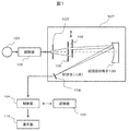
- FIG. 1 shows a schematic diagram of a spectrophotometer which is Embodiment 1 of the present invention.
- the spectroscope In normal measurement, light from the white light source 101 passes through the sample chamber 102 in which the sample to be measured is placed and enters the spectroscope 107.
- the spectroscope is provided with an entrance slit 103, a concave diffraction grating 100, and a diode array 104, and light that has passed through the entrance slit 103 is irradiated onto the concave diffraction grating 100.
- the diffracted light from the concave diffraction grating 100 is detected by the diode array 104.
- the light detected by the diode array is digitally processed by the control unit 108 and then sent to the recording unit 109 for storage.
- the display unit 110 displays the data after digital processing.
- the light adjustment mechanism When confirming the performance of the spectrophotometer, the light adjustment mechanism is automatically or manually installed between the entrance slit 103 and the concave diffraction grating 100.
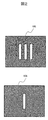
- FIG. 2 is a diagram showing an example of the configuration of the light adjustment mechanism.
- the light adjustment mechanism includes a first illumination position adjustment member 105 and a second illumination position adjustment member 106.
- the first illumination position adjustment member is provided with one or more openings
- the second illumination position adjustment member 106 is provided with one or more openings.
- the second illumination position adjusting member 106 can be moved manually or automatically. By moving the second illumination position adjustment member 106, the illumination position of the light incident on the concave diffraction grating is changed.
- FIG. 3 is a diagram illustrating another example of the configuration of the light adjustment mechanism.
- openings having a width of a are provided at intervals D in the short direction. Further, the second illumination position adjusting member 106 is provided with openings having a width of a in the short direction at a distance D + a, and the second illumination position adjusting member 106 can be moved manually or automatically. is there.
- the illumination position of the light incident on the concave diffraction grating is changed by moving the second illumination position adjusting member 106. At this time, when one illumination position is illuminated, the other illumination positions are shielded from light.
- By providing a plurality of openings of the second illumination position adjusting member it is possible to shorten the distance to which the second illumination position adjusting member is moved when changing the illumination position compared to the case of one opening. is there.
- the configuration of the illumination position adjusting member has one illumination position. Any structure can be used as long as it is a structure in which other illumination positions are shielded when illuminated.
- FIG. 4 is a diagram showing an example of the illumination position of the concave diffraction grating.
- the light from the white light source is incident on the spectroscope 107 in a state where no sample is installed in the sample chamber 102.
- the light incident on the spectroscope passes through the opening of the first illumination position adjusting member 105 and is irradiated to the second illumination position adjusting member 106. Only the light that has passed through the opening of the illumination position adjusting member 106 is applied to the concave diffraction grating.
- the second illumination position adjusting member 106 By moving the second illumination position adjusting member 106, the illumination position is changed from illumination position 1 to illumination position 3, and optical characteristics are measured at each illumination position.
- FIG. 5 is a flowchart for measuring the light intensity of the white light source 101 in order to confirm the performance of the concave diffraction grating.
- a light adjusting mechanism is installed between the entrance slit 103 and the concave diffraction grating 100 (step 501), and an illumination position is set (step 502).
- the second illumination position adjusting member 106 is moved to a position corresponding to the illumination position set in step 502 (step 503), and the light intensity at each wavelength is measured at that position (step 504).
- the measurer confirms the measurement result and determines the end of measurement (step 505). When the measurement is continued, step 502 to step 505 are repeated.
- the light adjustment mechanism is removed (step 506), and the light intensity measurement is terminated.
- the state of degradation can be grasped in detail. Furthermore, the state of deterioration can be grasped and the result can be displayed on the display unit 110. This can prompt the user to replace the deteriorated concave optical element.
- Embodiment 2 of the present invention will be described with reference to FIGS.
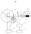
- FIG. 7 shows a concave diffraction grating inspection apparatus that is Embodiment 2 of the present invention.
- the concave diffraction grating inspection apparatus includes a concave diffraction grating 100, a laser light source 201 that irradiates light to the concave diffraction grating, a light beam expanding optical system 203 that expands light from the laser light source, and a concave diffraction grating.
- a linear motion stage 206 for changing is provided.
- Reference numeral 202 denotes a laser power source for driving the laser light source at a constant output
- 209 denotes a stage driving device for driving the rotary stage 205 and the linear motion stage 206
- 210 denotes a current measuring device for the photodetector 208
- 211 denotes a current measuring device 210.
- This is a stage control / data processing apparatus that processes data based on the current value of and controls the drive command for the stage.
- the light from the laser light source 201 is magnified by the light beam enlarging optical system 203 and applied to the concave diffraction grating installed on the stage 204. Diffracted light from the concave diffraction grating is imaged at different positions for each wavelength.
- FIG. 8 is a diagram showing the imaging position of the concave diffraction grating.
- d is the interval between the grooves carved in the concave diffraction grating
- m is the order of the diffracted light.
- the imaging position is given by [Equation 2] based on the diffraction angle ⁇ obtained by [Equation 1] and the curvature radius R of the concave diffraction grating.
- Determine the measurement wavelength range to include the wavelength of the laser light source used for the light source of the device, determine the diffraction angle and imaging position in the measurement wavelength range in advance, and rotate to the calculated diffraction angle and imaging position.
- the light intensity at the diffraction angle and the light intensity at other than the diffraction angle are measured.
- the stray light value is calculated from the ratio of the light intensity at the measured diffraction angle and the light intensity at an angle other than the diffraction angle.
- a first illumination position adjustment member 105 and a second illumination position adjustment member 106 are provided between the concave diffraction grating 100 and the laser light source 201, and the second illumination position adjustment member 106 is moved.
- the illumination position of the light incident on the concave diffraction grating can be changed.
- the stray light value it is possible to confirm the deterioration state of the concave diffraction grating and determine whether or not to replace the concave grating.
- the result of the determination can be displayed on the display unit 110 to prompt the user to exchange.
- SYMBOLS 100 Concave diffraction grating, 102 ... Sample chamber, 103 ... Incidence slit, 104 ... Diode array, 105 ... 1st illumination position adjustment member, 106 ... 2nd illumination position adjustment member, 107 ... Spectroscope, 108 ... Control part DESCRIPTION OF SYMBOLS 109 ... Recording part 110 ... Display part 201 ... Laser light source 202 ... Laser power supply 203 ... Light beam expansion optical system 204 ... Concave diffraction grating installation stage 205 ... Rotation stage 206 ... Linear motion stage 207 ... Exit slit, 208 ... photodetector, 209 ... stage drive device, 210 ... current measuring device, 211 ... stage control / data processing device
Landscapes
- Physics & Mathematics (AREA)
- General Physics & Mathematics (AREA)
- Spectroscopy & Molecular Physics (AREA)
- Chemical & Material Sciences (AREA)
- Analytical Chemistry (AREA)
- Investigating Or Analysing Materials By Optical Means (AREA)
- Spectrometry And Color Measurement (AREA)
Abstract
凹面回折格子の劣化や仕上がり形状のばらつきによる光学的性能の低下を把握することができる分光光度計、分光光度計の性能確認方法および凹面回折格子の検査装置を提供する。 本発明の特徴は、凹面回折格子100へ入射する白色光源101の光を、第一の照明位置調整部材105と第二の照明位置調整部材106を用いて照明位置を変更させることを可能とすると共に、それぞれの照明位置で凹面回折格子の光学特性をダイオードアレイ108で測定する機能を備えたところにある。
Description
本発明は、分光光度計、分光光度計の性能確認方法及び凹面回折格子の検査装置に係わり、特に凹面回折格子の光学特性のばらつきを把握するのに好適な分光光度計の構成、分光光度計の性能確認方法、および凹面回折格子の検査装置の構成に関する。
分光光度計は光源から発せられる光を分光し、所望の波長の成分のみを取り出してから試料に照射するか、または光源から発せられる光を試料に導いた後に所望の波長の光成分のみを取り出し、試料の透過率や反射率などを測定する。分光光度計では、波長分散素子として、一次元方向に溝が周期的に配列された回折格子が広く用いられている。
回折格子は、基板表面に鋸歯形状が複数本形成された光学素子で、分光光度計のほか、キャピラリアレイ電気泳動装置、液体クロマトグラフ、生化学自動分析装置等の光学式の分析装置に搭載され、波長分散するための素子として用いられる。
回折格子の種類には主に格子面が平面状の平面回折格子と、格子面が球状またはトロイド状の凹面回折格子などがある。凹面回折格子は、平面回折格子とは異なり分光作用と同時に集光作用や結像作用がある。このため光学系を構成する光学素子の数を少なくすることができるため、多くの装置に使用されている。
分光光度計に使用されている凹面回折格子は、空気中の埃や水分が表面に付着することにより劣化することがある。凹面回折格子の劣化は分光光度計の性能に著しく影響を及ぼすため、装置に設置されている凹面回折格子について、定期的に劣化の状態を確認する必要がある。凹面回折格子の評価方法については特許文献1に、装置に実装した条件で凹面光学素子単体の迷光を測定することが記載されている。
図6に凹面回折格子の断面形状の概略図を示す。凹面回折格子は球状またはトロイド状の曲面に溝が刻まれているため、格子面の端部と中央部では溝の高さや、溝の周期など仕上がり形状にばらつきが生じることがある。このような仕上がり形状のばらつきは凹面回折格子の分光作用や結像作用に影響を及ぼす。このため仕上がり形状のばらつきを把握する必要がある。また、分光光度計の性能確認を行う場合においても、凹面回折格子の格子面内の光学特性のばらつきの測定を行うことで、劣化の状態を詳細に把握することが可能となる。
従来の分光光度計や凹面回折格子の検査装置では、凹面回折格子へ入射させる光の照明位置を変更する機能がなかったため、性能確認を行う際、凹面回折格子の格子面上の光学特性のばらつきを測定することができていなかった。
また、特許文献1では凹面回折格子へ入射する光は凹面回折格子の格子面全体に照射されており異なる位置で測定することが考慮されていない。このため仕上がり形状のばらつきを検査することができていなかった。
本発明は上記課題を解決するためになされたものであり、その目的とするところは光調整機構を用いて凹面回折格子に入射する光の照明位置を変化させ、光学特性の測定を行うことができる分光光度計、分光光度計の性能確認方法と、凹面回折格子に形成された溝の仕上がり形状のばらつきを測定することができる検査装置を提供することにある。
本発明の特徴は、凹面回折格子へ入射する光を、光調整機構を用いて照明位置を変更させることを可能とすると共に、それぞれの照明位置で光学特性の測定を行う機能を分光光光度計及び凹面回折格子の検査装置に備えたところである。
本発明よれば、凹面回折格子に形成された溝の仕上がり形状のばらつきを測定することができ、凹面回折格子の格子面内の異なる位置の光学特性を測定することができる分光光度計および溝凹面回折格子の検査装置を提供することができる。
以下、本発明の実施例1について、図1~図5を参照して説明する。
図1に本発明の実施例1である分光光度計の概略図を示す。
通常の測定では、白色光源101からの光は、測定対象の試料を設置する試料室102を通過し、分光器107に入射される。分光器内には入射スリット103、凹面回折格子100、ダイオードアレイ104が備えられており、入射スリット103を通過した光は、凹面回折格子100へ照射される。凹面回折格子100からの回折された光を、ダイオードアレイ104で検出する。ダイオードアレイにより検出された光は、制御部108でデジタル処理された後、記録部109に送られ保存される。また表示部110では、デジタル処理後のデータを表示させる。
分光光度計の性能確認を行う場合には、光調整機構を、自動または手動で入射スリット103と凹面回折格子100との間に設置する。
図2は光調整機構の構成の一例を示す図である。
光調整機構は第一の照明位置調整部材105と第二の照明位置調整部材106から構成される。第一の照明位置調整部材には、1つ以上の開口部が設けてあり、第二の照明位置調整部材106には、1つまたは複数の開口部が設けてある。第二の照明位置調整部材106は手動または自動で移動させることが可能である。第二の照明位置調整部材106を移動さることにより、凹面回折格子へ入射する光の照明位置を変更する。
図3は光調整機構の構成の他例を表す図である。
図3の第一の照明位置調整部材105には、短手方向にaの幅をもつ開口部が間隔Dで設けられている。また第二の照明位置調整部材106には短手方向にaの幅をもつ開口部が間隔D+aで設けられており、第二の照明位置調整部材106は手動または自動で移動が可能である。
第二の照明位置調整部材106を移動させることにより、凹面回折格子へ入射する光の照明位置を変更する。このとき1つの照明位置が照明されているときには、他の照明位置は遮光される構造とする。第二照明位置調整部材の開口部を複数設けることにより、開口部が1つの場合と比べて照明位置を変更する際に、第二の照明位置調整部材の移動させる距離を短くすることが可能である。
本実施例では分かり易く説明するために、詳細に説明したものであり、必ずしも説明した全ての構成を備えるものに限定されるものではない、特に照明位置調整部材の構成は、1つの照明位置が照明されているときに、他の照明位置が遮光される構造であればよく変更することが可能である。
図4は凹面回折格子の照明位置の一例を示す図である。
試料室102に試料を設置していない状態で、白色光源からの光を分光器107へ入射させる。分光器へ入射した光は、第一の照明位置調整整部材105の開口部を通過し、第二の照明位置調整部材106に照射される。照明位置調整部材106の開口部を通過した光のみが、凹面回折格子に照射される。前記第二の照明位置調整部材106を移動させることにより、照明位置を照明位置1~照明位置3まで変更させ、それぞれの照明位置で光学特性の測定を行う。
図5は凹面回折格子の性能確認を行うために、白色光源101の光強度を測定するフローチャートである。光調整機構を入射スリット103と凹面回折格子100の間に設置し(ステップ501)し、照明位置を設定する(ステップ502)。ステップ502で設定した照明位置に対応した位置に第二の照明位置調整部材106を移動させ(ステップ503)、その位置で各波長における光強度を測定する(ステップ504)。測定者は測定結果を確認し、測定終了の判断を行う(ステップ505)。測定を継続する場合は、ステップ502~ステップ505を繰り返し行う。測定を終了すると判断した場合には、光調整機構を取外し(ステップ506)、光強度の測定を終了させる。
このような実施例とすることにより、分光光度計に設置された凹面回折格子の格子面内の分光特性のばらつきの測定ができるようになるため、劣化の状態を詳細に把握することができる。 さらに劣化の状態を把握し、その結果を表示部110に表示することができる。これによって、劣化した凹面光学素子の交換をユーザーに促すことができる。
このような実施例とすることにより、分光光度計に設置された凹面回折格子の格子面内の分光特性のばらつきの測定ができるようになるため、劣化の状態を詳細に把握することができる。 さらに劣化の状態を把握し、その結果を表示部110に表示することができる。これによって、劣化した凹面光学素子の交換をユーザーに促すことができる。
以下、本発明の実施例2について、図7~図8を参照して説明する。
図7に本発明の実施例2である凹面回折格子の検査装置を示す。
本実施例の凹面回折格子の検査装置は、凹面回折格子100と凹面回折格子に光を照射するレーザ光源201と、レーザ光源からの光を拡大する光束拡大光学系203と、凹面回折格子を設置するためのステージ204と、凹面回折格子からの回折光を検出する光検知器208と、前記光検知器208を回転させるための回転ステージ205と、凹面回折格子の中心と検知器との距離を変更するための直動ステージ206を備えている。
なお、202はレーザ光源を一定の出力で駆動するレーザ電源、209は回転ステージ205と直動ステージ206を駆動するステージ駆動装置、210は光検知器208の電流計測装置、211は電流計測装置210の電流値に基づいてデータを処理し、ステージの駆動命令を制御するステージ制御・データ処理装置である。
レーザ光源201からの光は、光束拡大光学系203により拡大され、ステージ204に設置した凹面回折格子に照射される。凹面回折格子からの回折光は、波長毎に異なる位置に結像される。
図8は凹面回折格子の結像位置を示した図である。
レーザ光源201からの光は、光束拡大光学系203により拡大され、ステージ204に設置した凹面回折格子に照射される。凹面回折格子からの回折光は、波長毎に異なる位置に結像される。
図8は凹面回折格子の結像位置を示した図である。
回折光の波長をλとし、凹面回折格子へ入射する光の入射角をαとすると、回折角βは[数1]で与えられる。

ここでdは凹面回折格子に刻まれた溝の間隔、mは回折光の次数である。[数1]で求めた回折角βと、凹面回折格子の曲率半径Rにより、結像位置は[数2]で与えられる。

装置の光源に用いていているレーザ光源の波長を含むように、測定波長範囲を決定し、測定波長範囲において回折角と結像位置を予め求めておき、求めた回折角と結像位置に回転ステージ205および直動ステージを206用いて光検知器208を動かしながら、光強度を測定することにより、回折角での光強度と、回折角以外での光強度の測定を行う。測定した回折角での光強度と回折角以外の角度での光強度の比から迷光値を算出する。
凹面回折格子100とレーザ光源201との間には、第一の照明位置調整部材105と第二の照明位置調整部材106が備えられており、前記第二の照明位置調整部材106を移動させることにより、凹面回折格子へ入射する光の照明位置を変更することができる。
このような実施例をとることにより、凹面回折格子の格子面内の迷光値の算出結果から、仕上がり形状のばらつきを検査することができる。
さらに迷光値の算出結果から、凹面回折格子の劣化の状態を確認し、凹面格子を交換するかどうかを判断することができる。判断した結果を、表示部110に表示させ、ユーザーに交換を促すことができる。
100…凹面回折格子、102…試料室、103…入射スリット、104…ダイオードアレイ、105…第一の照明位置調整部材、106…第二の照明位置調整部材、107…分光器、108…制御部、109…記録部、110…表示部、201…レーザ光源、202…レーザ電源、203…光束拡大光学系、204…凹面回折格子設置用ステージ、205…回転ステージ、206…直動ステージ、207…出射スリット、208…光検知器、209…ステージ駆動装置、210…電流計測装置、211…ステージ制御・データ処理装置
Claims (8)
- 凹面光学素子に向かって光を照射する光源と、凹面光学素子を設置する設置部と、前記設置部に設置された凹面光学素子から反射された光を検出する検出器と、前記光源と前記設置部の間に位置する光調節機構と、を備えた分析装置であって、
前記光調節機構は、第一の照射位置調節部材と第二の照射位置調節部材から構成され、前記第一の照射位置調節部材は複数の光開口部を有し、前記第二の照射位置調節部材は1または複数の光開口部を有し、前記第二の照射位置調節部材は移動可能であることを特徴とする分析装置。 - 請求項1記載の分析装置であって、
前記第二の照射位置調節部材は1つの光開口部を有することを特徴とする分析装置。 - 請求項1記載の分析装置であって、
前記第二の照射位置調節部材は前記第一の照射位置調節部材に対向した位置に配置され、前記第一の照射位置調節部材に対向して移動可能であることを特徴とする分析装置。 - 請求項1記載の分析装置であって、
前記検出器で測定した結果から、凹面回折格子の劣化の状態を確認し、凹面格子を交換するか否かを表示する表示部をさらに備えたことを特徴とする分析装置。 - 請求項1記載の分析装置であって、
前記検出器を移動させる移動機構を備えることを特徴とする分析装置。 - 請求項5記載の分析装置であって、
前記移動機構は、前記設置部と前記検出器の間の距離を変更することを特徴とする分析装置。 - 請求項1記載の分析装置であって、
前記検出器は、検出結果から前記設置部上の凹面回折格子の迷光値を算出することを特徴とする分析装置。 - 請求項1記載の分析装置は分光光度計であることを特徴とする分析装置
Priority Applications (1)
| Application Number | Priority Date | Filing Date | Title |
|---|---|---|---|
| PCT/JP2015/083520 WO2017094048A1 (ja) | 2015-11-30 | 2015-11-30 | 分光光度計、分光光度計の性能確認方法及び凹面回折格子の検査装置 |
Applications Claiming Priority (1)
| Application Number | Priority Date | Filing Date | Title |
|---|---|---|---|
| PCT/JP2015/083520 WO2017094048A1 (ja) | 2015-11-30 | 2015-11-30 | 分光光度計、分光光度計の性能確認方法及び凹面回折格子の検査装置 |
Publications (1)
| Publication Number | Publication Date |
|---|---|
| WO2017094048A1 true WO2017094048A1 (ja) | 2017-06-08 |
Family
ID=58796504
Family Applications (1)
| Application Number | Title | Priority Date | Filing Date |
|---|---|---|---|
| PCT/JP2015/083520 Ceased WO2017094048A1 (ja) | 2015-11-30 | 2015-11-30 | 分光光度計、分光光度計の性能確認方法及び凹面回折格子の検査装置 |
Country Status (1)
| Country | Link |
|---|---|
| WO (1) | WO2017094048A1 (ja) |
Citations (5)
| Publication number | Priority date | Publication date | Assignee | Title |
|---|---|---|---|---|
| US5926272A (en) * | 1997-04-08 | 1999-07-20 | Curtiss; Lawrence E. | Spectroscopy |
| JP2006250859A (ja) * | 2005-03-14 | 2006-09-21 | Nikon Corp | 面形状測定方法、面形状測定装置、投影光学系の製造方法、投影光学系、及び投影露光装置 |
| JP2007285847A (ja) * | 2006-04-17 | 2007-11-01 | Hitachi High-Tech Manufacturing & Service Corp | 分光光度計 |
| JP2014048068A (ja) * | 2012-08-29 | 2014-03-17 | Dkk Toa Corp | 分光光度計 |
| JP2014134449A (ja) * | 2013-01-10 | 2014-07-24 | Hitachi High-Technologies Corp | 凹面光学素子の測定装置及び凹面回折格子の測定装置並びに平面回折格子の測定装置 |
-
2015
- 2015-11-30 WO PCT/JP2015/083520 patent/WO2017094048A1/ja not_active Ceased
Patent Citations (5)
| Publication number | Priority date | Publication date | Assignee | Title |
|---|---|---|---|---|
| US5926272A (en) * | 1997-04-08 | 1999-07-20 | Curtiss; Lawrence E. | Spectroscopy |
| JP2006250859A (ja) * | 2005-03-14 | 2006-09-21 | Nikon Corp | 面形状測定方法、面形状測定装置、投影光学系の製造方法、投影光学系、及び投影露光装置 |
| JP2007285847A (ja) * | 2006-04-17 | 2007-11-01 | Hitachi High-Tech Manufacturing & Service Corp | 分光光度計 |
| JP2014048068A (ja) * | 2012-08-29 | 2014-03-17 | Dkk Toa Corp | 分光光度計 |
| JP2014134449A (ja) * | 2013-01-10 | 2014-07-24 | Hitachi High-Technologies Corp | 凹面光学素子の測定装置及び凹面回折格子の測定装置並びに平面回折格子の測定装置 |
Similar Documents
| Publication | Publication Date | Title |
|---|---|---|
| CN110986818B (zh) | 光谱光束轮廓计量 | |
| US7397561B2 (en) | Spectroscopy system | |
| JP4950813B2 (ja) | 分光エリプソメータ、膜厚測定装置および分光エリプソメータのフォーカス調整方法 | |
| JP4804727B2 (ja) | 光走査型共焦点顕微鏡 | |
| US20120268744A1 (en) | Multiple measurement techniques including focused beam scatterometry for characterization of samples | |
| US11933717B2 (en) | Sensitive optical metrology in scanning and static modes | |
| WO2002029374A1 (en) | Differential numerical aperture methods and device | |
| WO2008013909A2 (en) | Multiple measurement techniques including focused beam scatterometry for characterization of samples | |
| US7564547B2 (en) | Spectroscopy system | |
| KR20110127122A (ko) | 시료분석장치 | |
| JP2012255781A (ja) | 反射光の基準測定装置及びその装置の較正方法 | |
| US9551612B2 (en) | Tandem dispersive range monochromator | |
| US9891104B2 (en) | Spectroscopic detector | |
| US7321423B2 (en) | Real-time goniospectrophotometer | |
| KR20070056947A (ko) | 샘플의 특성을 검출하는 광학 시스템 | |
| US9546903B2 (en) | Data knitting tandem dispersive range monochromator | |
| JP7240829B2 (ja) | パターン構造のx線測定 | |
| WO2017094048A1 (ja) | 分光光度計、分光光度計の性能確認方法及び凹面回折格子の検査装置 | |
| KR20220074626A (ko) | HSI(Hyper Spectral Imaging) 장치 및 이를 포함하는 검사 장치 | |
| JP4672498B2 (ja) | コンクリート劣化因子検出方法及び検出装置 | |
| US20180094978A1 (en) | Spectroscopy with Tailored Spectral Sampling | |
| JP5261862B2 (ja) | 回折格子の迷光測定方法および装置 | |
| JP4672496B2 (ja) | コンクリート劣化因子検出方法 | |
| WO2002012950A1 (en) | Method of analyzing spectrum using multi-slit member and multi-channel spectrograph using the same | |
| US9885670B2 (en) | Inspection apparatus and adjusting method |
Legal Events
| Date | Code | Title | Description |
|---|---|---|---|
| 121 | Ep: the epo has been informed by wipo that ep was designated in this application |
Ref document number: 15909678 Country of ref document: EP Kind code of ref document: A1 |
|
| NENP | Non-entry into the national phase |
Ref country code: DE |
|
| 122 | Ep: pct application non-entry in european phase |
Ref document number: 15909678 Country of ref document: EP Kind code of ref document: A1 |
|
| NENP | Non-entry into the national phase |
Ref country code: JP |