WO2017092474A1 - Structure de dérivation, dispositif de ventilation et procédé de ventilation - Google Patents
Structure de dérivation, dispositif de ventilation et procédé de ventilation Download PDFInfo
- Publication number
- WO2017092474A1 WO2017092474A1 PCT/CN2016/098690 CN2016098690W WO2017092474A1 WO 2017092474 A1 WO2017092474 A1 WO 2017092474A1 CN 2016098690 W CN2016098690 W CN 2016098690W WO 2017092474 A1 WO2017092474 A1 WO 2017092474A1
- Authority
- WO
- WIPO (PCT)
- Prior art keywords
- fresh air
- damper
- ventilation
- bypass
- exhaust
- Prior art date
Links
Images


Classifications
-
- F—MECHANICAL ENGINEERING; LIGHTING; HEATING; WEAPONS; BLASTING
- F24—HEATING; RANGES; VENTILATING
- F24F—AIR-CONDITIONING; AIR-HUMIDIFICATION; VENTILATION; USE OF AIR CURRENTS FOR SCREENING
- F24F7/00—Ventilation
- F24F7/04—Ventilation with ducting systems, e.g. by double walls; with natural circulation
- F24F7/06—Ventilation with ducting systems, e.g. by double walls; with natural circulation with forced air circulation, e.g. by fan positioning of a ventilator in or against a conduit
- F24F7/08—Ventilation with ducting systems, e.g. by double walls; with natural circulation with forced air circulation, e.g. by fan positioning of a ventilator in or against a conduit with separate ducts for supplied and exhausted air with provisions for reversal of the input and output systems
-
- F—MECHANICAL ENGINEERING; LIGHTING; HEATING; WEAPONS; BLASTING
- F24—HEATING; RANGES; VENTILATING
- F24F—AIR-CONDITIONING; AIR-HUMIDIFICATION; VENTILATION; USE OF AIR CURRENTS FOR SCREENING
- F24F11/00—Control or safety arrangements
-
- F—MECHANICAL ENGINEERING; LIGHTING; HEATING; WEAPONS; BLASTING
- F24—HEATING; RANGES; VENTILATING
- F24F—AIR-CONDITIONING; AIR-HUMIDIFICATION; VENTILATION; USE OF AIR CURRENTS FOR SCREENING
- F24F11/00—Control or safety arrangements
- F24F11/30—Control or safety arrangements for purposes related to the operation of the system, e.g. for safety or monitoring
-
- F—MECHANICAL ENGINEERING; LIGHTING; HEATING; WEAPONS; BLASTING
- F24—HEATING; RANGES; VENTILATING
- F24F—AIR-CONDITIONING; AIR-HUMIDIFICATION; VENTILATION; USE OF AIR CURRENTS FOR SCREENING
- F24F11/00—Control or safety arrangements
- F24F11/89—Arrangement or mounting of control or safety devices
-
- F—MECHANICAL ENGINEERING; LIGHTING; HEATING; WEAPONS; BLASTING
- F24—HEATING; RANGES; VENTILATING
- F24F—AIR-CONDITIONING; AIR-HUMIDIFICATION; VENTILATION; USE OF AIR CURRENTS FOR SCREENING
- F24F13/00—Details common to, or for air-conditioning, air-humidification, ventilation or use of air currents for screening
- F24F13/02—Ducting arrangements
-
- F—MECHANICAL ENGINEERING; LIGHTING; HEATING; WEAPONS; BLASTING
- F24—HEATING; RANGES; VENTILATING
- F24F—AIR-CONDITIONING; AIR-HUMIDIFICATION; VENTILATION; USE OF AIR CURRENTS FOR SCREENING
- F24F13/00—Details common to, or for air-conditioning, air-humidification, ventilation or use of air currents for screening
- F24F13/28—Arrangement or mounting of filters
-
- F—MECHANICAL ENGINEERING; LIGHTING; HEATING; WEAPONS; BLASTING
- F24—HEATING; RANGES; VENTILATING
- F24F—AIR-CONDITIONING; AIR-HUMIDIFICATION; VENTILATION; USE OF AIR CURRENTS FOR SCREENING
- F24F13/00—Details common to, or for air-conditioning, air-humidification, ventilation or use of air currents for screening
- F24F13/30—Arrangement or mounting of heat-exchangers
-
- F—MECHANICAL ENGINEERING; LIGHTING; HEATING; WEAPONS; BLASTING
- F24—HEATING; RANGES; VENTILATING
- F24F—AIR-CONDITIONING; AIR-HUMIDIFICATION; VENTILATION; USE OF AIR CURRENTS FOR SCREENING
- F24F2110/00—Control inputs relating to air properties
-
- Y—GENERAL TAGGING OF NEW TECHNOLOGICAL DEVELOPMENTS; GENERAL TAGGING OF CROSS-SECTIONAL TECHNOLOGIES SPANNING OVER SEVERAL SECTIONS OF THE IPC; TECHNICAL SUBJECTS COVERED BY FORMER USPC CROSS-REFERENCE ART COLLECTIONS [XRACs] AND DIGESTS
- Y02—TECHNOLOGIES OR APPLICATIONS FOR MITIGATION OR ADAPTATION AGAINST CLIMATE CHANGE
- Y02B—CLIMATE CHANGE MITIGATION TECHNOLOGIES RELATED TO BUILDINGS, e.g. HOUSING, HOUSE APPLIANCES OR RELATED END-USER APPLICATIONS
- Y02B30/00—Energy efficient heating, ventilation or air conditioning [HVAC]
- Y02B30/70—Efficient control or regulation technologies, e.g. for control of refrigerant flow, motor or heating
Definitions
- the invention relates to the technical field of ventilation and ventilation, and particularly relates to a bypass structure, a ventilation device and a ventilation method.
- the existing full heat exchange type new fan adopts the following method: an over-air passage is arranged on the indoor exhaust side air flow passage in the machine, and the wind is controlled by the damper The continuity of the channel.
- the user controls the opening and closing of the damper through the control panel.
- the damper When the damper is closed, the outdoor fresh air and the indoor exhaust air can be exchanged through the heat exchange core; when the control damper is opened, the outdoor fresh air enters the room through the heat exchange core, and the indoor exhaust air The outdoor is discharged through the set air passage.
- the main principle is: when the damper is opened, the indoor exhaust airflow no longer passes through the heat exchange core, but directly excludes the outdoor through the wind passage, while the outdoor fresh air still enters the room through the heat exchange core, so that the two airflows
- the heat exchange is not performed in the heat exchange core, thereby achieving the purpose of not using the full heat exchange function when the temperature difference between the indoor side and the outdoor side is small.
- the above existing solution can solve the problem that the outdoor fresh air and the indoor exhaust air do not exchange heat when the temperature difference is small, at the same time, it also brings some new problems, and the solution causes the resistance difference between the fresh air side and the exhaust side, and the use
- the air volume of the exhaust air is larger than the air volume of the fresh air, which causes the indoor side to exhibit a negative pressure, which causes the unfiltered air outside to directly enter the room, and the core of the heat exchange core is too windy and long.
- the time is in an environment with pressure difference on both sides, which will increase the loss of the heat exchange core body, and the over-wind efficiency of the wind passage is low, which increases the overall energy consumption of the unit and reduces the heat exchange efficiency.
- the object of the present invention is to provide a bypass structure to solve the problem of low bypass efficiency of the bypass structure in the prior art, to eliminate the pressure difference between the indoor side and the outdoor side, and to reduce heat exchange in the ventilation device.
- the loss of the core provides conditions.
- Another object of the present invention is to provide a ventilation device and a ventilation method, which solves the problem of the prior art ventilation device causing a pressure difference between the indoor side and the outdoor side and a large loss of the heat exchange core.
- the present invention provides a bypass structure for a ventilation device, the bypass structure being juxtaposed with a main ventilation structure in the ventilation device, the bypass structure including independent of each other a fresh air bypass passage and an exhaust bypass passage capable of providing a flow passage for outdoor fresh air flowing through the ventilation device from the outdoor entrance chamber, the exhaust bypass passage being capable of flowing through
- the indoor exhaust of the ventilation device provides a flow passage from the indoor discharge outdoor, and the fresh air bypass passage is provided with a first damper for opening or closing the fresh air bypass passage; A second damper is provided in the passage, and the second damper is used to open or close the exhaust bypass passage.
- first damper and the second damper are interlocking structures.
- a motor for controlling driving of the first damper and the second damper
- the controller being signally connected to a control end of the motor and capable of transmitting to the motor And a control signal to control an opening and closing state and/or an opening angle of the first damper and the second damper.
- a static pressure detecting device is further configured to detect static pressure in the fresh air bypass passage and the exhaust bypass passage, and transmit the measured static pressure pressure signal to the controller.
- the controller is capable of adjusting the rotational speed of the exhaust fan of the ventilation device and/or the fresh air blower of the ventilation device according to the static pressure signal.
- the method further includes: detecting a rotation speed of the exhaust fan of the ventilation device and a rotation speed of the fresh air fan of the ventilation device, and transmitting the measured rotation speed signal to the controller,
- the controller is capable of adjusting the rotational speed of the exhaust fan and/or the rotational speed of the fresh air fan according to the rotational speed signal.
- a stepped knot is arranged in the fresh air bypass passage and the exhaust bypass passage So that the first upper chamber located in the upper layer of the ventilation device can communicate with the second lower chamber located in the lower layer of the ventilation device through the fresh air bypass passage, and the ventilation device is The second upper chamber located in the upper layer communicates with the first lower chamber located in the lower layer of the ventilation device through the exhaust bypass passage.
- the present invention also provides a ventilation device including a main ventilation structure and the above-described bypass structure, which can be realized by the opening and closing of the first damper and the second damper.
- the method further includes a first upper chamber located on the upper side and having an outdoor fresh air inlet, and a first lower chamber located on the lower floor and having an indoor exhaust vent, and located near the indoor side.
- a second upper chamber having an indoor exhaust air inlet and a second lower chamber having an outdoor fresh air supply opening, wherein the ventilation device can communicate with the first through the fresh air bypass passage
- An upper chamber and the second lower chamber communicating with the second upper chamber and the first lower chamber through the exhaust bypass passage, and capable of communicating through the main ventilation structure a first upper chamber and the second lower chamber, and the second upper chamber and the first lower chamber are connectable by the main ventilation structure.
- a filter is arranged in the first upper chamber and/or the second lower chamber to filter outdoor fresh air entering the room.
- the ventilation device is a full heat exchange type fan
- the main ventilation structure includes a heat exchange core capable of exchanging heat between outdoor fresh air and indoor exhaust air
- the ventilation device further includes a motor, a controller, and a first temperature sensor for detecting an outdoor fresh air temperature at the outdoor fresh air inlet and a second temperature sensor for detecting an indoor exhaust air temperature at the indoor exhaust air inlet, the motor for driving the The first damper and the second damper are rotated
- the controller is signally connected to the control end of the motor, and is capable of transmitting a control signal to the motor to control the opening of the first damper and the second damper a closed state and/or an opening angle
- the first temperature sensor and the second temperature sensor transmitting the measured temperature signal to the controller, the controller being capable of controlling the first according to the temperature signal An opening and closing state and/or an opening angle of the damper and the second damper.
- the present invention also provides a ventilation method that can be operated to implement:
- a main ventilation mode in which the first damper and the second damper are closed, so that outdoor fresh air enters the room from the outside through the main ventilation structure, and the indoor exhaust air passes through
- the main ventilation structure is discharged indoors from the room;
- a bypass ventilation mode in the bypass ventilation mode, opening the first damper and the second damper, so that outdoor fresh air enters the room from the outdoor through the fresh air bypass passage, and the indoor platoon is The wind is discharged from the room to the outside through the exhaust bypass passage.
- Providing a controller connecting the controller to a control end signal of the motor, and transmitting, by the controller, a control signal to the motor to control an opening and closing state of the first damper and the second damper / or open the angle.
- the static pressure detecting device detects the static pressure in the fresh air bypass passage and the exhaust bypass passage, and transmits the measured static pressure pressure signal to the controller, The controller adjusts a rotational speed of the exhaust fan of the ventilation device and/or the fresh air blower of the ventilation device according to the static pressure pressure signal.
- the rotation speed detecting device detects the rotation speed of the exhaust fan of the ventilation device and the rotation speed of the fresh air fan of the ventilation device, and transmits the measured rotation speed signal to the controller, The controller adjusts a rotation speed of the exhaust fan and/or a rotation speed of the fresh air fan according to the rotation speed signal.
- the ventilation device is a full heat exchange type fan
- the main ventilation structure includes a heat exchange core capable of performing heat exchange between the outdoor fresh air and the indoor exhaust air
- the ventilation method further includes:
- the bypass structure of the present invention can allow the outdoor fresh air and the indoor exhaust air to flow through the fresh air bypass passage and the exhaust air bypass passage respectively by providing mutually independent fresh air bypass passages and exhaust air bypass passages.
- the utility model can solve the problem that the bypass structure in the prior art has low bypass efficiency due to only having one over-air passage, and improves the bypass ventilation efficiency, and can also solve the problem of the bypass ventilation efficiency in the bypass structure in the prior art. Try to eliminate the pressure difference between the indoor side and the outdoor side to prevent unfiltered air from entering the room directly.
- This structure can also provide conditions for reducing the loss of the heat exchange core in the ventilation device.
- the ventilation device of the present invention can be ventilated by the bypass structure, and the outdoor fresh air and the indoor exhaust air do not need to pass through the main ventilation structure.
- the pressure difference between the indoor side and the outdoor side caused by bypassing the indoor exhaust air only through the wind passage can be eliminated, and the loss of the main ventilation structure can be reduced, for example, the loss of the heat exchange core can be reduced, and the equipment can be reduced. Replacement rate, reduce cost, and reduce energy consumption to achieve energy saving and environmental protection.
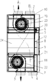
- FIG. 1 is a front elevational view of one embodiment of a ventilation device of the present invention.
- Figure 2 is a left side elevational view of the ventilating apparatus of the embodiment of Figure 1.
- FIG 3 is a front elevational view of the ventilating apparatus of the embodiment of Figure 1 with the damper closed.
- Figure 4 is a left side elevational view of the ventilating apparatus of the embodiment of Figure 3.
- Figure 5 is a front elevational view of the ventilating apparatus of the embodiment of Figure 1 with the damper open.
- Figure 6 is a left side elevational view of the ventilation device of the embodiment of Figure 5.
- Figure 7 is a front elevational view of the fresh air bypass passage and the exhaust bypass passage of the present invention with the damper closed.
- Figure 8 is a front elevational view of the fresh air bypass passage and the exhaust bypass passage of the present invention with the damper open.
- Figure 9 is a schematic view showing the structure of an embodiment of the damper of the present invention.
- a bypass structure is first proposed.
- the bypass structure is used for a ventilation device, the bypass structure and the ventilation device
- the main ventilation structure is juxtaposed, the bypass structure includes mutually independent fresh air bypass passages 8 and exhaust air bypass passages 9, and the fresh air bypass passages 8 can be outdoor fresh air flowing through the ventilation device
- the exhaust bypass passage 9 being capable of providing a flow passage for the indoor exhaust air flowing through the ventilation device to be discharged from the indoor discharge chamber, wherein the fresh air bypass passage 8 is provided with a first damper 51.
- the exhaust air bypass passage 9 is provided with a second damper 52 for opening or closing the fresh air bypass passage 8 and the exhaust air bypass passage 9, respectively.
- the above-mentioned bypass structure can allow the outdoor fresh air and the indoor exhaust air to flow through the fresh air bypass passage and the exhaust air bypass passage respectively by providing mutually independent fresh air bypass passages and exhaust air bypass passages, without passing through the ventilation device.
- the main ventilation structure in the prior art can solve the problem that the bypass structure in the prior art has low bypass efficiency due to only having one over-air passage, improve the bypass ventilation efficiency, and can try to eliminate the indoor side and the outdoor side.
- the pressure difference prevents unfiltered air from entering the room directly, and the structure can also provide conditions for reducing the loss of the heat exchange core in the ventilation device.
- the first damper 51 is used to open or close the fresh air bypass passage 8, or to change the opening size of the fresh air bypass passage 8 and the second damper 52 is used to open or close the exhaust bypass passage 9, or change the exhaust bypass The opening size of the channel 9. That is, the first damper 51 and the second damper 52 may have only two states of opening and closing, and may have various states of opening, closing, and between opening and closing.
- the first damper 51 and the second damper 52 can be separately designed and act as their own.
- the first damper 51 and the second damper 52 can also be a linkage structure, and the linkage structure can realize the synchronization of the first damper 51 and the second damper 52.
- the control is such that the fresh air bypass passage 8 and the exhaust bypass passage 9 are simultaneously opened or closed, or the same opening size is maintained.
- first damper 51 and the second damper 52 may be integrally formed, that is, as a unitary structure, as long as the action can be achieved.
- the damper 5 formed by the first damper 51 and the second damper 52 is located in the indoor exhaust air flowing through the air outlet side of the air passage and the outdoor fresh air flowing through the air passage.
- the damper 5 On the wind side, when the damper 5 is in the open or closed state, the first damper 51 on the upper side is thrust, and the second damper 52 on the lower side is suctioned, thereby abutting each other.
- the force of the airflow on the damper 5 reduces the torque required by the motor 6.
- the bypass structure may further include a motor 6 for driving the first damper 51 and the second damper 52 to rotate, and a controller 20 and the motor 6
- the control terminal signal is connected, and a control signal can be sent to the motor 6 to control the opening and closing state and/or the opening angle of the first damper 51 and the second damper 52.
- the motor 6 can also be replaced with other power components, such as an engine or a cylinder, and the motor 6 can be specifically a stepping motor or a servo motor.
- Controller 20 may employ a digital signal processor, an application specific integrated circuit, a field programmable gate array or other programmable logic device, discrete gate or transistor logic device, discrete hardware components, or any combination of the above.
- the bypass structure may further include a static pressure detecting device 17 for detecting the new wind side. a static pressure in the passage 8 and the exhaust bypass passage 9, and transmitting the measured static pressure signal to the controller 20, the controller 20 being capable of adjusting the static pressure signal according to the static pressure signal.
- the static pressure detecting device 17 may be provided to detect the static pressure in the fresh air bypass passage 8 and the exhaust bypass passage 9 at the same time; or two may be provided to detect the fresh air bypass passage 8 and the exhaust bypass passage 9 respectively. Static pressure.
- the static pressure detecting device 17 may be a general pressure detecting device. When the pressure detected by the general pressure detecting device is a dynamic pressure, the dynamic pressure may be converted into a static pressure according to a parameter such as a wind speed in the passage.
- the fresh air bypass passage 8 and the exhaust bypass passage 9 are directly related to the rotational speeds of the exhaust fan 23 and the fresh air blower 22, the fresh air bypass passage 8 and the exhaust air detected by the static pressure detecting device 17 are used.
- the static pressure in the bypass passage 9 can be adjusted to adjust the static pressure of the indoor side and/or the outdoor side by adjusting the rotational speed of the exhaust fan 23 and/or the fresh air blower 22, respectively, and the indoor side and the outdoor side are adjusted. The pressure difference approaches zero.
- Corresponding preset conditions may be set in the controller 20 such that when the static pressure detecting device 17 detects that the static pressure in the fresh air bypass passage 8 and the exhaust bypass passage 9 meets the preset condition, no adjustment is made; The static pressure detecting device 17 detects the fresh air bypass passage 8 and the exhaust side When the static pressure in the passage 9 does not satisfy the preset condition, the corresponding adjustment measures are adopted. Preset conditions and adjustment measures can be set according to actual needs.
- the rotation speed of the fresh air blower 22 may be increased, or the rotation speed of the exhaust fan 23 may be reduced, or the rotation speeds of the exhaust fan 23 and the fresh air fan 22 may be adjusted at the same time;
- the static pressure in the exhaust bypass passage 9 is large, the rotational speed of the exhaust fan 23 can be increased, or the rotational speed of the fresh air blower 22 can be reduced, or the rotational speeds of the exhaust fan 23 and the fresh air blower 22 can be adjusted at the same time.
- a method of providing the rotational speed detecting means 18 can be employed, which is more direct and simple.
- the rotation speed detecting device 18 is configured to detect the rotation speed of the exhaust fan 23 of the ventilation device and the rotation speed of the fresh air fan 22 of the ventilation device, and transmit the measured rotation speed signal to the controller 20,
- the controller 20 is capable of adjusting the rotational speed of the exhaust fan 23 and/or the rotational speed of the fresh air blower 22 based on the rotational speed signal.
- the rotation speed detecting device may be provided with one, and simultaneously detects the rotation speeds of the exhaust fan 23 and the fresh air fan 22; two may also be provided to detect the rotation speeds of the exhaust fan 23 and the fresh air fan 22, respectively. Since the pressure is directly related to the rotational speed, in an ideal case, the rotational speeds of the exhaust fan 23 and the fresh air blower 22 are equal, and the pressures on the indoor side and the outdoor side are considered to be nearly equal.
- Corresponding preset conditions may be set in the controller 20 such that when the rotation speed detecting device 18 detects that the rotation speeds of the exhaust fan 23 and the fresh air fan 22 satisfy the preset condition, no adjustment is made; when the rotation speed detecting device 18 detects the row When the rotational speeds of the air blower 23 and the fresh air blower 22 do not meet the preset conditions, corresponding adjustment measures are adopted. Preset conditions and adjustment measures can be set according to actual needs.
- the rotational speed of the fresh air blower 22 when the rotational speed of the fresh air blower 22 is large, the rotational speed of the exhaust air blower 23 can be increased, or the rotational speed of the fresh air blower 22 can be reduced, and at the same time, the rotational speed of the exhaust air blower 23 can be increased, so that the two tend to Balance; when the rotational speed of the exhaust fan 23 is large, the rotational speed of the fresh air blower 22 can be increased, or the rotational speed of the exhaust fan 23 can be reduced, and the rotational speed of the fresh air blower 22 can be increased at the same time, so that the two tend to balance.
- the rotational speeds of the exhaust fan 23 and the fresh air blower 22 may be controlled by the controller 20 or may be controlled by a dedicated rotational speed control device 16.
- the speed control device 16 can be disposed at a position close to the exhaust fan 23 and/or the fresh air fan 22 to realize the exhaust fan 23 And accurate control of the fresh air blower 22.
- the passage partition 12 divides the bypass structure into mutually independent fresh air bypass passages 8 and exhaust air bypass passages 9.
- a stepped structure is disposed in the fresh air bypass passage 8 and the exhaust bypass passage 9 to enable the first upper chamber 32 located in the upper layer of the ventilation device to pass through the fresh air bypass passage 8
- the second lower chamber 33 located in the lower layer of the ventilating device is in communication
- the second upper chamber 34 located in the upper layer of the ventilating device is located through the exhaust bypass passage 9 and the ventilating device
- the lower lower layer chamber 31 of the lower layer is in communication.
- the ventilation device is set to two layers above and below to save the overall occupation space of the ventilation device, and for the stability of the installation and the overall balance of the ventilation device, the fresh air fan 22 and the exhaust fan 23 are generally located in the lower chamber, and the outdoor fresh air And the indoor exhaust air enters the air through the upper chamber, so the bypass structure needs to have a step structure to connect the upper chamber and the lower chamber.
- the specific structural form of the step structure can be adjusted as needed, and the purpose of the setting is mainly to connect the upper and lower chambers.
- the fresh air bypass passage 8 and the exhaust bypass passage 9 can be regarded as a transition passage, so that the outdoor fresh air entering the first upper chamber 32 passes through the fresh air bypass passage 8, and then reaches the lower layer from the upper layer and enters the second lower chamber 33; After the indoor exhaust entering the second upper chamber 34 passes through the exhaust bypass passage 9, the upper layer reaches the lower layer and enters the first lower chamber 31.
- the present invention also provides a ventilation device including a main ventilation structure and the above-described bypass structure.
- a ventilation device including a main ventilation structure and the above-described bypass structure.
- the ventilation device of the present invention can be ventilated by the bypass structure, and the outdoor fresh air and the indoor exhaust air no longer pass the main ventilation structure.
- the pressure difference between the indoor side and the outdoor side caused by bypassing the indoor exhaust air only through the wind passage can be eliminated, and the loss of the main ventilation structure can be reduced, for example, the loss of the heat exchange core can be reduced, and the equipment can be reduced. Replacement rate, reduce cost, and reduce energy consumption to achieve energy saving and environmental protection.
- the opening and closing of the first damper 51 and the second damper 52 can realize the main ventilation mode and the side
- the bypass structure is in a closed state, and the airflow cannot pass, so the ventilation device passes through the main
- the ventilation structure performs ventilation; when the first damper 51 and the second damper 52 are opened, the bypass structure is in a through-flow state, as shown in FIG. 5, FIG. 6, and FIG. 8, since the gas enters the main ventilation structure, it must overcome a certain condition.
- bypass structure is basically a pressureless passage
- the fresh air blower 22 and the exhaust air blower 23 have a suction effect on the outdoor fresh air and the indoor exhaust air, so the outdoor fresh air and the indoor exhaust air are directly exchanged through the bypass structure. gas.
- the ventilation device may include a first upper chamber 32 located on the upper side and having an outdoor fresh air inlet 2 near the outdoor side, and a lower floor and an indoor exhaust a first lower chamber 31 of the exhaust vent 1, and a second upper chamber 34 located on the upper side and having an indoor exhaust air inlet 4 adjacent to the indoor side, and a second lower unit having an outdoor fresh air supply opening 3 a lower chamber 33, the ventilation device capable of communicating the first upper chamber 32 and the second lower chamber 33 through the fresh air bypass passage 8, and communicating through the exhaust bypass passage 9 a second upper chamber 34 and the first lower chamber 31, and capable of communicating the first upper chamber 32 and the second lower chamber 33, respectively, through the main ventilation structure, and the first Two upper chambers 34 and the first lower chamber 31. That is, the ventilation device can communicate the first upper chamber 32 and the second lower chamber 33 through the main ventilation structure, and can communicate with the second upper chamber 34 and the chamber through the main ventilation structure.
- the first lower chamber 31 is described.
- a first partition 19 is disposed between the first upper chamber 32 and the first lower chamber 31 so that the two are spatially independent of each other, and the exhaust fan 23 is located in the first lower chamber 31;
- a second partition 21 is disposed between the second upper chamber 34 and the second lower chamber 33 so that the two are spatially independent of each other, and the fresh air blower is located in the second lower chamber 33.
- the fresh air bypass passage 8 communicates with the second tuyere 13 and the fourth tuyere 15 so that the outdoor fresh air enters the room without passing through the main ventilation structure, and the exhaust bypass passage 9 communicates with the first tuyere 11 and the third tuyere 14 so that the indoor exhaust does not Exhausted outside through the main ventilation structure.
- the flow path of the outdoor fresh air is: under the action of the fresh air blower 22 located in the second lower chamber 33, the outdoor fresh air enters the first by the outdoor fresh air inlet 2
- the upper chamber 32 is then passed through the main ventilation structure into the second lower chamber
- the chamber 33 has recently entered the room through the outdoor fresh air supply port 3; in the main ventilation mode, the flow path of the indoor exhaust air is: under the action of the exhaust fan 23 located in the first lower chamber 31, the indoor row
- the wind enters the second upper chamber 34 from the indoor exhaust air inlet 4, and then enters the first lower chamber 31 through the main ventilation structure, and is recently discharged outside the indoor exhaust vent 1 .
- the flow path of the outdoor fresh air is: under the action of the fresh air blower 22 located in the second lower chamber 33, the outdoor fresh air enters the first upper chamber 32 from the outdoor fresh air inlet 2, Then enter the fresh air bypass passage 8 through the second tuyere 13, and then enter the second lower chamber 33 through the fourth tuyere 15, and finally enter the room through the outdoor fresh air supply port 3; in the bypass ventilation mode, the indoor exhaust flow The path is: under the action of the exhaust fan 23 located in the first lower chamber 31, the indoor exhaust air enters the second upper chamber 34 from the indoor exhaust air inlet 4, and then enters the exhaust through the first tuyere 11 The bypass passage 9 then enters the first lower chamber 31 via the third tuyere 14, and is recently discharged outside the indoor exhaust vent 1 .
- a filter is provided in the first upper chamber 32 and/or the second lower chamber 33 to filter the outdoor fresh air entering the room.
- the bypass structure of the present invention can be applied to a variety of different types of ventilation devices, such as a full heat exchange type fan, a filter type blower, or a dehumidification new fan.
- the main ventilation structure is the heat exchange core 24, which is a key component of the full heat exchange type fan.
- the heat exchange core 24 can serve the purpose of heat exchange between the two, so that the fresh air entering the indoor air absorbs the residual heat of the indoor exhaust air in the heat exchange core 24, and improves the indoor access. Fresh air temperature.
- the damper 5 (including the first damper 51 and the second damper 52) can be opened to enter the bypass ventilation mode.
- the ventilation device is a full heat exchange type fan
- the main ventilation structure includes a heat exchange core 24 capable of heat exchange between outdoor fresh air and indoor exhaust air
- the ventilation device further includes a motor 6.
- the control The device 20 is capable of controlling an opening and closing state and/or an opening angle of the first damper 51 and the second damper 52 according to the temperature signal.
- the controller 20 controls The first damper 51 and the second damper 52 are opened, and the ventilating device enters the bypass ventilation mode; when the first temperature sensor 10 and the second temperature sensor 7 detect the temperature of the outdoor fresh air at the outdoor fresh air inlet 2 and the indoor exhaust When the temperature difference of the indoor exhaust air at the air inlet 4 does not satisfy the preset condition, the controller 20 controls the first damper 51 and the second damper 52 to be closed, and the ventilating device enters the main ventilation mode.
- the preset condition may be that the absolute value of the difference between the outdoor fresh air temperature and the indoor exhaust air temperature is not greater than a preset difference, and the preset difference may be set by the actual needs of the user, such as 5° C. or 8° C. .
- the present invention also provides a ventilation method that can be operated to implement:
- a main ventilation mode in which the first damper 51 and the second damper 52 are closed, so that outdoor fresh air enters the room from the outdoor through the main ventilation structure, and the indoor platoon is The wind is discharged from the room through the main ventilation structure;
- a bypass ventilation mode in the bypass ventilation mode, opening the first damper 51 and the second damper 52, so that outdoor fresh air enters the room from the outdoor through the fresh air bypass passage 8
- the indoor exhaust air is discharged from the room to the outside through the exhaust bypass passage 9.
- the ventilation method may further include:
- the ventilation method may further include:
- a static pressure detecting device 17 is provided, and the static pressure in the fresh air bypass passage 8 and the exhaust bypass passage 9 is detected by the static pressure detecting device 17, and the measured static pressure signal is transmitted to the The controller 20 adjusts the rotational speed of the exhaust fan 23 of the ventilation device and/or the fresh air blower 22 of the ventilation device according to the static pressure signal.
- the ventilation method may further include:
- the controller 20 adjusts the rotational speed of the exhaust fan 23 and/or the rotational speed of the fresh air blower 22 according to the rotational speed signal.
- the ventilation device is a full heat exchange type fan
- the main ventilation structure includes a heat exchange core 24 capable of performing heat exchange between the outdoor fresh air and the indoor exhaust air
- the ventilation method further includes:
- the temperature of the outdoor fresh air at the tuyere 4 transmits the measured temperature signal to the controller 20, and the controller 20 controls the first damper 51 and the second damper 52 according to the temperature signal. Open and close state and / or open angle.
- the ventilation method may further include:
- the first damper 51 and the second damper 52 are closed, otherwise the first damper 51 and the second damper 52 are opened by the controller 20.
- the damper 5 When the first temperature detecting device 10 and the second temperature detecting device 7 detect that the difference between the outdoor fresh air temperature and the indoor exhaust air temperature is not lower than the set value ⁇ (for example, 5 ° C or lower), the damper 5 is in a closed state.
- the airflow in the full heat exchange type fan is as shown in Fig. 3, Fig. 4 and Fig. 7.
- the outdoor fresh air passes through the outdoor fresh air inlet 2, the first upper chamber 32, and the heat exchange core 24 under the suction of the fresh air fan 22.
- the second lower chamber 33 and the outdoor air blower port 3 constitute a new air passage B 1 enters the chamber; exhaust chamber at the exhaust suction fan 23 through the indoor exhaust inlet 4, the second upper chamber 34
- the heat exchange core 24, a first lower chamber 31 and exhaust chamber exhaust ports constituting exhaust passage 1 A 1 is discharged outside.
- the outdoor fresh air and the indoor exhaust air flow in different flow paths in the heat exchange core 24, and the outdoor fresh air and the indoor exhaust air exchange temperature and humidity in the heat exchange core 24 due to the difference in temperature and humidity.
- the damper 5 When the first temperature detecting device 10 and the second temperature detecting device 7 detect that the difference between the outdoor fresh air temperature and the indoor exhaust air temperature is lower than the set value ⁇ (for example, 5 ° C or lower), the damper 5 is opened, and the outdoor fresh air is opened after the damper is opened.
- the two airflows with the indoor exhaust air enter the indoor and the outdoor through the respective bypass air passages.
- the airflow in the full heat exchange type fan is as shown in Fig. 5, Fig. 6, and Fig. 8, and the outdoor fresh air is sucked in the fresh air blower 22.
- the fresh air passage formed by the outdoor fresh air inlet 2, the first upper chamber 32, the second tuyere 13, the fresh air bypass passage 8, the fourth tuyere 15, the second lower chamber 33, and the outdoor fresh air supply port 3 B 2 enters the room; the indoor exhaust air passes through the indoor exhaust air inlet 4, the second upper chamber 34, the first tuyere 11, the exhaust bypass passage 9, and the third tuyere under the suction of the exhaust fan 23. 14.
- the exhaust passage A 2 formed by the first lower chamber 31 and the indoor exhaust vent 1 is discharged to the outside.
- the static pressure detecting device 17 or the rotational speed detecting device 18 is respectively configured to detect the static pressure of the fresh air passage and the exhaust air passage or the rotational speeds of the fresh air blower and the exhaust air blower, and the static pressure difference or the rotational speed existing when the fresh air passage and the exhaust air passage are detected.
- the rotational speed of the exhaust fan and/or the rotational speed of the fresh air blower are adjusted accordingly to adjust the exhaust air volume and the air intake volume to make the pressure difference between the two sides of the passage. Consistent with the set value, there is no phenomenon that the room presents a negative pressure due to excessive exhaust air to allow outdoor air to enter the room from the room gap.
- the set value ⁇ of the temperature difference that controls the opening and closing state of the damper can be set by the user within a certain range according to the actual use situation or the manual control mode can be adopted according to the need, and the bypass ventilation mode can be further increased according to the actual use situation. Time, to meet the different needs of different users in the housing temperature, thereby improving user comfort.
- bypass structure the ventilation device and the ventilation method of the present invention
- the bypass structure, the ventilation device and the ventilation method embodiment of the present invention have at least the advantages of adopting a fresh air bypass
- the passage and the exhaust bypass passage pass the outdoor fresh air and the indoor exhaust air through the different air passages for double bypass, and the outdoor fresh air and the indoor exhaust air enter the indoor or the outdoor through the respective bypass passages, thereby realizing in the spring,
- the temperature difference between the two seasons is small, and the function of bypass ventilation is not required when the heat exchange function is used, and the indoor side and the outdoor side caused by the single bypass of the exhaust air flow are eliminated.
- the pressure difference causes the outdoor fresh air to be directly inhaled into the room from the room gap, and avoids the loss of the core due to the different pressures on both sides of the heat exchange core in the full heat exchange type fan, and the double bypass design improves the bypass change. Gas efficiency reduces energy consumption.
Abstract
L'invention concerne une structure de dérivation, un dispositif de ventilation et un procédé de ventilation, la structure de dérivation étant utilisée pour le dispositif de ventilation. La structure de dérivation est disposée en parallèle à une structure de ventilation primaire dans le dispositif de ventilation. La structure de dérivation comprend un passage (8) de dérivation d'air frais et un passage (9) de dérivation d'air d'évacuation, indépendants l'un de l'autre. Le passage (8) de dérivation d'air frais est conçu pour assurer un passage d'écoulement pour l'air frais extérieur coulant à travers le dispositif de ventilation du côté extérieur vers le côté intérieur, et le passage (9) de dérivation d'air d'évacuation est conçu pour assurer un passage d'écoulement pour l'air d'évacuation intérieur coulant à travers le dispositif de ventilation du côté intérieur vers le côté extérieur. Un premier registre d'écoulement d'air (51) est disposé dans le passage (8) de dérivation d'air frais et un second registre d'écoulement d'air (52) est disposé dans le passage (9) de dérivation d'air d'évacuation, afin d'ouvrir ou de fermer le passage (8) de dérivation d'air frais et le passage (9) de dérivation d'air d'évacuation, respectivement. Au moyen de la structure de dérivation, l'efficacité de ventilation de dérivation est améliorée, et une différence de pression entre le côté intérieur et le côté extérieur peut être éliminée, empêchant l'air non filtré d'entrer directement dans le côté intérieur et réduisant l'usure de la structure de ventilation primaire. Le dispositif et le procédé de ventilation utilisent la structure de dérivation dans la ventilation, réduisant l'usure de la structure de ventilation primaire.
Applications Claiming Priority (2)
| Application Number | Priority Date | Filing Date | Title |
|---|---|---|---|
| CN201510868358.0A CN105352105B (zh) | 2015-11-30 | 2015-11-30 | 旁通结构、换气设备及换气方法 |
| CN201510868358.0 | 2015-11-30 |
Publications (1)
| Publication Number | Publication Date |
|---|---|
| WO2017092474A1 true WO2017092474A1 (fr) | 2017-06-08 |
Family
ID=55328124
Family Applications (1)
| Application Number | Title | Priority Date | Filing Date |
|---|---|---|---|
| PCT/CN2016/098690 WO2017092474A1 (fr) | 2015-11-30 | 2016-09-12 | Structure de dérivation, dispositif de ventilation et procédé de ventilation |
Country Status (2)
| Country | Link |
|---|---|
| CN (1) | CN105352105B (fr) |
| WO (1) | WO2017092474A1 (fr) |
Cited By (5)
| Publication number | Priority date | Publication date | Assignee | Title |
|---|---|---|---|---|
| CN107702250A (zh) * | 2017-10-11 | 2018-02-16 | 宁波奈兰环境系统有限公司 | 新风热泵一体机 |
| CN107842969A (zh) * | 2017-11-22 | 2018-03-27 | 奥普家居股份有限公司 | 一种具有旁通门的新风机 |
| CN108036438A (zh) * | 2018-01-24 | 2018-05-15 | 核工业西南勘察设计研究院有限公司 | 一种节能新风系统 |
| CN110173791A (zh) * | 2019-05-11 | 2019-08-27 | 中山新风谷环境科技有限公司 | 一种室外新风及室内净化的空气清洁器 |
| CN114963389A (zh) * | 2022-06-07 | 2022-08-30 | Tcl空调器(中山)有限公司 | 空气处理装置及空调器 |
Families Citing this family (7)
| Publication number | Priority date | Publication date | Assignee | Title |
|---|---|---|---|---|
| CN105352105B (zh) * | 2015-11-30 | 2018-05-11 | 珠海格力电器股份有限公司 | 旁通结构、换气设备及换气方法 |
| KR101819046B1 (ko) * | 2017-07-19 | 2018-02-28 | 오충록 | 컨버전스 전열교환기 |
| CN107504568A (zh) * | 2017-08-29 | 2017-12-22 | 奥普家居股份有限公司 | 厨房空调 |
| CN108195019A (zh) * | 2018-01-29 | 2018-06-22 | 奥普家居股份有限公司 | 双向流全热新风装置 |
| CN110608497A (zh) * | 2019-09-05 | 2019-12-24 | 珠海格力电器股份有限公司 | 新风空调器、控制方法及存储介质 |
| CN113015416A (zh) * | 2021-03-09 | 2021-06-22 | 广东海悟科技有限公司 | 散热装置及数据中心系统 |
| CN114151860B (zh) * | 2021-12-03 | 2023-01-06 | 珠海格力电器股份有限公司 | 一种新风空调机及其控制方法 |
Citations (9)
| Publication number | Priority date | Publication date | Assignee | Title |
|---|---|---|---|---|
| CN2648333Y (zh) * | 2003-10-16 | 2004-10-13 | 代伯清 | 独立新风空调器 |
| US20060270335A1 (en) * | 2005-05-31 | 2006-11-30 | Lg Electronics Inc. | Total heat exchanger and ventilation system using the same |
| CN101617176A (zh) * | 2007-02-23 | 2009-12-30 | 大金工业株式会社 | 空气调节换气装置 |
| CN103398443A (zh) * | 2013-08-02 | 2013-11-20 | 重庆海润节能技术股份有限公司 | 一种洁净新风系统及洁风方法 |
| CN105003996A (zh) * | 2015-08-19 | 2015-10-28 | 珠海格力电器股份有限公司 | 全热交换新风机 |
| CN105258272A (zh) * | 2015-11-30 | 2016-01-20 | 珠海格力电器股份有限公司 | 全热交换型新风机 |
| CN105352105A (zh) * | 2015-11-30 | 2016-02-24 | 珠海格力电器股份有限公司 | 旁通结构、换气设备及换气方法 |
| CN205156237U (zh) * | 2015-11-30 | 2016-04-13 | 珠海格力电器股份有限公司 | 全热交换型新风机 |
| CN205156238U (zh) * | 2015-11-30 | 2016-04-13 | 珠海格力电器股份有限公司 | 旁通结构及换气设备 |
Family Cites Families (5)
| Publication number | Priority date | Publication date | Assignee | Title |
|---|---|---|---|---|
| KR100369212B1 (ko) * | 1999-07-07 | 2003-01-24 | 한국과학기술연구원 | 내연 기관의 배기 소음 및/또는 기체 이송 시스템의 덕트내부의 소음을 제어하기 위한 장치 및 방법 |
| JP2008309381A (ja) * | 2007-06-13 | 2008-12-25 | Mitsubishi Electric Corp | 熱交換換気装置 |
| CN101603718B (zh) * | 2009-07-23 | 2011-03-30 | 青岛海信日立空调系统有限公司 | 一种风管式空调室内机静压的自动识别方法及其系统 |
| US20130048267A1 (en) * | 2010-06-11 | 2013-02-28 | Mitsubishi Electric Corporation | Ventilation and air-conditioning apparatus and method for controlling the same |
| CN201837020U (zh) * | 2010-10-13 | 2011-05-18 | 成都交大房产开发有限责任公司 | 节能型新风、空调控制系统 |
-
2015
- 2015-11-30 CN CN201510868358.0A patent/CN105352105B/zh active Active
-
2016
- 2016-09-12 WO PCT/CN2016/098690 patent/WO2017092474A1/fr active Application Filing
Patent Citations (9)
| Publication number | Priority date | Publication date | Assignee | Title |
|---|---|---|---|---|
| CN2648333Y (zh) * | 2003-10-16 | 2004-10-13 | 代伯清 | 独立新风空调器 |
| US20060270335A1 (en) * | 2005-05-31 | 2006-11-30 | Lg Electronics Inc. | Total heat exchanger and ventilation system using the same |
| CN101617176A (zh) * | 2007-02-23 | 2009-12-30 | 大金工业株式会社 | 空气调节换气装置 |
| CN103398443A (zh) * | 2013-08-02 | 2013-11-20 | 重庆海润节能技术股份有限公司 | 一种洁净新风系统及洁风方法 |
| CN105003996A (zh) * | 2015-08-19 | 2015-10-28 | 珠海格力电器股份有限公司 | 全热交换新风机 |
| CN105258272A (zh) * | 2015-11-30 | 2016-01-20 | 珠海格力电器股份有限公司 | 全热交换型新风机 |
| CN105352105A (zh) * | 2015-11-30 | 2016-02-24 | 珠海格力电器股份有限公司 | 旁通结构、换气设备及换气方法 |
| CN205156237U (zh) * | 2015-11-30 | 2016-04-13 | 珠海格力电器股份有限公司 | 全热交换型新风机 |
| CN205156238U (zh) * | 2015-11-30 | 2016-04-13 | 珠海格力电器股份有限公司 | 旁通结构及换气设备 |
Cited By (7)
| Publication number | Priority date | Publication date | Assignee | Title |
|---|---|---|---|---|
| CN107702250A (zh) * | 2017-10-11 | 2018-02-16 | 宁波奈兰环境系统有限公司 | 新风热泵一体机 |
| CN107842969A (zh) * | 2017-11-22 | 2018-03-27 | 奥普家居股份有限公司 | 一种具有旁通门的新风机 |
| CN108036438A (zh) * | 2018-01-24 | 2018-05-15 | 核工业西南勘察设计研究院有限公司 | 一种节能新风系统 |
| CN110173791A (zh) * | 2019-05-11 | 2019-08-27 | 中山新风谷环境科技有限公司 | 一种室外新风及室内净化的空气清洁器 |
| CN110173791B (zh) * | 2019-05-11 | 2024-03-22 | 怡家环境科技(广东)有限公司 | 一种室外新风及室内净化的空气清洁器 |
| CN114963389A (zh) * | 2022-06-07 | 2022-08-30 | Tcl空调器(中山)有限公司 | 空气处理装置及空调器 |
| CN114963389B (zh) * | 2022-06-07 | 2023-12-05 | Tcl空调器(中山)有限公司 | 空气处理装置及空调器 |
Also Published As
| Publication number | Publication date |
|---|---|
| CN105352105B (zh) | 2018-05-11 |
| CN105352105A (zh) | 2016-02-24 |
Similar Documents
| Publication | Publication Date | Title |
|---|---|---|
| WO2017092474A1 (fr) | Structure de dérivation, dispositif de ventilation et procédé de ventilation | |
| CN110375365A (zh) | 一种楼宇智能排烟系统及其控制方法 | |
| CN105387554A (zh) | 换气装置和换气方法 | |
| CN110388692A (zh) | 用于近零能耗建筑的冷热源新风装置及其控制方法 | |
| CN103953996B (zh) | 双向流主机及其控制方法 | |
| CN109556219B (zh) | 变风量空调机组及其控制方法 | |
| CN110567081A (zh) | 一种全热交换新风机及其控制方法 | |
| CN207146794U (zh) | 空气调节装置 | |
| CN206556189U (zh) | 一种空调新风控制系统 | |
| WO2018028528A1 (fr) | Système de mur-rideau écologique thermostatique intelligent de détection de vent et procédé de régulation de température | |
| WO2020088446A1 (fr) | Corps de panneau de climatiseur, climatiseur, et procédé d'équilibrage de l'entrée et de la sortie d'air d'un climatiseur | |
| CN105928126A (zh) | 全热交换器 | |
| WO2021168983A1 (fr) | Climatiseur, procédé de commande pour climatiseur, et support de stockage lisible par ordinateur | |
| CN104515207B (zh) | 多贯流空调器及其控制方法 | |
| JP2014173826A (ja) | 全熱交換型の換気装置 | |
| CN205156238U (zh) | 旁通结构及换气设备 | |
| CN105928172A (zh) | 导风板及全热交换器 | |
| WO2021082453A1 (fr) | Procédé de commande d'unité intérieure de climatiseur | |
| CN209165730U (zh) | 一种空调面板体及空调器 | |
| CN110410876A (zh) | 一种空调器室外机以及空调器 | |
| WO2021203818A1 (fr) | Système de refroidissement par évaporation et système de salle d'ordinateurs | |
| CN207299383U (zh) | 一种外置多面进风壁挂式新风机 | |
| CN106642499B (zh) | 全热交换装置 | |
| CN205002314U (zh) | 一种螺旋式空调送风结构 | |
| CN207196855U (zh) | 组合式空调器流道结构和组合式空调器 |
Legal Events
| Date | Code | Title | Description |
|---|---|---|---|
| 121 | Ep: the epo has been informed by wipo that ep was designated in this application |
Ref document number: 16869785 Country of ref document: EP Kind code of ref document: A1 |
|
| NENP | Non-entry into the national phase |
Ref country code: DE |
|
| 122 | Ep: pct application non-entry in european phase |
Ref document number: 16869785 Country of ref document: EP Kind code of ref document: A1 |