WO2017090499A1 - 表示制御装置及び表示制御方法 - Google Patents
表示制御装置及び表示制御方法 Download PDFInfo
- Publication number
- WO2017090499A1 WO2017090499A1 PCT/JP2016/084019 JP2016084019W WO2017090499A1 WO 2017090499 A1 WO2017090499 A1 WO 2017090499A1 JP 2016084019 W JP2016084019 W JP 2016084019W WO 2017090499 A1 WO2017090499 A1 WO 2017090499A1
- Authority
- WO
- WIPO (PCT)
- Prior art keywords
- image
- bird
- eye
- difference
- display
- Prior art date
- Legal status (The legal status is an assumption and is not a legal conclusion. Google has not performed a legal analysis and makes no representation as to the accuracy of the status listed.)
- Ceased
Links
Images


Classifications
-
- H—ELECTRICITY
- H04—ELECTRIC COMMUNICATION TECHNIQUE
- H04N—PICTORIAL COMMUNICATION, e.g. TELEVISION
- H04N5/00—Details of television systems
- H04N5/222—Studio circuitry; Studio devices; Studio equipment
- H04N5/262—Studio circuits, e.g. for mixing, switching-over, change of character of image, other special effects ; Cameras specially adapted for the electronic generation of special effects
- H04N5/2625—Studio circuits, e.g. for mixing, switching-over, change of character of image, other special effects ; Cameras specially adapted for the electronic generation of special effects for obtaining an image which is composed of images from a temporal image sequence, e.g. for a stroboscopic effect
-
- B—PERFORMING OPERATIONS; TRANSPORTING
- B60—VEHICLES IN GENERAL
- B60R—VEHICLES, VEHICLE FITTINGS, OR VEHICLE PARTS, NOT OTHERWISE PROVIDED FOR
- B60R1/00—Optical viewing arrangements; Real-time viewing arrangements for drivers or passengers using optical image capturing systems, e.g. cameras or video systems specially adapted for use in or on vehicles
- B60R1/002—Optical viewing arrangements; Real-time viewing arrangements for drivers or passengers using optical image capturing systems, e.g. cameras or video systems specially adapted for use in or on vehicles specially adapted for covering the peripheral part of the vehicle, e.g. for viewing tyres, bumpers or the like
-
- B—PERFORMING OPERATIONS; TRANSPORTING
- B60—VEHICLES IN GENERAL
- B60R—VEHICLES, VEHICLE FITTINGS, OR VEHICLE PARTS, NOT OTHERWISE PROVIDED FOR
- B60R1/00—Optical viewing arrangements; Real-time viewing arrangements for drivers or passengers using optical image capturing systems, e.g. cameras or video systems specially adapted for use in or on vehicles
- B60R1/20—Real-time viewing arrangements for drivers or passengers using optical image capturing systems, e.g. cameras or video systems specially adapted for use in or on vehicles
- B60R1/22—Real-time viewing arrangements for drivers or passengers using optical image capturing systems, e.g. cameras or video systems specially adapted for use in or on vehicles for viewing an area outside the vehicle, e.g. the exterior of the vehicle
- B60R1/23—Real-time viewing arrangements for drivers or passengers using optical image capturing systems, e.g. cameras or video systems specially adapted for use in or on vehicles for viewing an area outside the vehicle, e.g. the exterior of the vehicle with a predetermined field of view
-
- B—PERFORMING OPERATIONS; TRANSPORTING
- B60—VEHICLES IN GENERAL
- B60R—VEHICLES, VEHICLE FITTINGS, OR VEHICLE PARTS, NOT OTHERWISE PROVIDED FOR
- B60R21/00—Arrangements or fittings on vehicles for protecting or preventing injuries to occupants or pedestrians in case of accidents or other traffic risks
-
- G—PHYSICS
- G06—COMPUTING OR CALCULATING; COUNTING
- G06T—IMAGE DATA PROCESSING OR GENERATION, IN GENERAL
- G06T3/00—Geometric image transformations in the plane of the image
- G06T3/40—Scaling of whole images or parts thereof, e.g. expanding or contracting
- G06T3/4038—Image mosaicing, e.g. composing plane images from plane sub-images
-
- G—PHYSICS
- G06—COMPUTING OR CALCULATING; COUNTING
- G06T—IMAGE DATA PROCESSING OR GENERATION, IN GENERAL
- G06T5/00—Image enhancement or restoration
- G06T5/50—Image enhancement or restoration using two or more images, e.g. averaging or subtraction
-
- G—PHYSICS
- G06—COMPUTING OR CALCULATING; COUNTING
- G06T—IMAGE DATA PROCESSING OR GENERATION, IN GENERAL
- G06T5/00—Image enhancement or restoration
- G06T5/77—Retouching; Inpainting; Scratch removal
-
- H—ELECTRICITY
- H04—ELECTRIC COMMUNICATION TECHNIQUE
- H04N—PICTORIAL COMMUNICATION, e.g. TELEVISION
- H04N23/00—Cameras or camera modules comprising electronic image sensors; Control thereof
- H04N23/90—Arrangement of cameras or camera modules, e.g. multiple cameras in TV studios or sports stadiums
-
- H—ELECTRICITY
- H04—ELECTRIC COMMUNICATION TECHNIQUE
- H04N—PICTORIAL COMMUNICATION, e.g. TELEVISION
- H04N5/00—Details of television systems
- H04N5/222—Studio circuitry; Studio devices; Studio equipment
- H04N5/262—Studio circuits, e.g. for mixing, switching-over, change of character of image, other special effects ; Cameras specially adapted for the electronic generation of special effects
- H04N5/2628—Alteration of picture size, shape, position or orientation, e.g. zooming, rotation, rolling, perspective, translation
-
- H—ELECTRICITY
- H04—ELECTRIC COMMUNICATION TECHNIQUE
- H04N—PICTORIAL COMMUNICATION, e.g. TELEVISION
- H04N5/00—Details of television systems
- H04N5/44—Receiver circuitry for the reception of television signals according to analogue transmission standards
- H04N5/445—Receiver circuitry for the reception of television signals according to analogue transmission standards for displaying additional information
-
- H—ELECTRICITY
- H04—ELECTRIC COMMUNICATION TECHNIQUE
- H04N—PICTORIAL COMMUNICATION, e.g. TELEVISION
- H04N7/00—Television systems
- H04N7/18—Closed-circuit television [CCTV] systems, i.e. systems in which the video signal is not broadcast
-
- H—ELECTRICITY
- H04—ELECTRIC COMMUNICATION TECHNIQUE
- H04N—PICTORIAL COMMUNICATION, e.g. TELEVISION
- H04N7/00—Television systems
- H04N7/18—Closed-circuit television [CCTV] systems, i.e. systems in which the video signal is not broadcast
- H04N7/181—Closed-circuit television [CCTV] systems, i.e. systems in which the video signal is not broadcast for receiving images from a plurality of remote sources
-
- B—PERFORMING OPERATIONS; TRANSPORTING
- B60—VEHICLES IN GENERAL
- B60R—VEHICLES, VEHICLE FITTINGS, OR VEHICLE PARTS, NOT OTHERWISE PROVIDED FOR
- B60R2300/00—Details of viewing arrangements using cameras and displays, specially adapted for use in a vehicle
- B60R2300/10—Details of viewing arrangements using cameras and displays, specially adapted for use in a vehicle characterised by the type of camera system used
- B60R2300/105—Details of viewing arrangements using cameras and displays, specially adapted for use in a vehicle characterised by the type of camera system used using multiple cameras
-
- B—PERFORMING OPERATIONS; TRANSPORTING
- B60—VEHICLES IN GENERAL
- B60R—VEHICLES, VEHICLE FITTINGS, OR VEHICLE PARTS, NOT OTHERWISE PROVIDED FOR
- B60R2300/00—Details of viewing arrangements using cameras and displays, specially adapted for use in a vehicle
- B60R2300/30—Details of viewing arrangements using cameras and displays, specially adapted for use in a vehicle characterised by the type of image processing
- B60R2300/303—Details of viewing arrangements using cameras and displays, specially adapted for use in a vehicle characterised by the type of image processing using joined images, e.g. multiple camera images
-
- B—PERFORMING OPERATIONS; TRANSPORTING
- B60—VEHICLES IN GENERAL
- B60R—VEHICLES, VEHICLE FITTINGS, OR VEHICLE PARTS, NOT OTHERWISE PROVIDED FOR
- B60R2300/00—Details of viewing arrangements using cameras and displays, specially adapted for use in a vehicle
- B60R2300/60—Details of viewing arrangements using cameras and displays, specially adapted for use in a vehicle characterised by monitoring and displaying vehicle exterior scenes from a transformed perspective
- B60R2300/607—Details of viewing arrangements using cameras and displays, specially adapted for use in a vehicle characterised by monitoring and displaying vehicle exterior scenes from a transformed perspective from a bird's eye viewpoint
-
- G—PHYSICS
- G06—COMPUTING OR CALCULATING; COUNTING
- G06T—IMAGE DATA PROCESSING OR GENERATION, IN GENERAL
- G06T2207/00—Indexing scheme for image analysis or image enhancement
- G06T2207/10—Image acquisition modality
- G06T2207/10016—Video; Image sequence
-
- G—PHYSICS
- G06—COMPUTING OR CALCULATING; COUNTING
- G06T—IMAGE DATA PROCESSING OR GENERATION, IN GENERAL
- G06T2207/00—Indexing scheme for image analysis or image enhancement
- G06T2207/30—Subject of image; Context of image processing
- G06T2207/30248—Vehicle exterior or interior
- G06T2207/30252—Vehicle exterior; Vicinity of vehicle
Definitions
- the present disclosure relates to a display control device and a display control method.
- a vehicle-mounted camera mounted on a vehicle repeatedly captures a predetermined range around the vehicle, converts the captured image into a bird's-eye image that is viewed from above the vehicle, and displays the bird's-eye image on a display unit in the vehicle.
- Technology is known.
- Patent Document 1 discloses a technique for suppressing the shadow of the host vehicle in the image of the display unit from expanding with the movement of the vehicle in the history image composition technique.
- the in-vehicle camera is a rear camera that captures the rear of the vehicle, and a real area and a history area are provided in a storage unit (predetermined storage area).
- the real A area is an area for storing an image of a predetermined range that is further away from the vehicle among the rear parts of the vehicle divided in the front-rear direction.
- the real B area is an area for storing an image in a predetermined range closer to the vehicle.
- the history C area is an area for storing a bird's-eye view image outside the shooting range of the in-vehicle camera.
- the history B area is an area for storing bird's-eye images in the same range as the real B area.
- the bird's-eye image is configured in the history B area so that the current arrangement around the vehicle is reflected in the bird's-eye image in the history B area.
- the bird's-eye view image is configured in the history B region using the bird's-eye view image stored in the real A region based on the movement amount of the vehicle.
- a bird's-eye view image is configured in the history C region using the bird's-eye view image stored in the history B region based on the movement amount of the vehicle.
- the history image is synthesized using the bird's-eye image of the history B area that is configured based on the bird's-eye image of the real A area that is highly likely not to have a shadow.
- the shadow of the host vehicle is suppressed from being enlarged in the display image as the vehicle moves.
- the above-described enlargement problem is not limited to the shadow of the vehicle, but can also occur with respect to the irradiation light of the vehicle.
- vehicle irradiation light include headlamp irradiation light and tail lamp irradiation light.
- the irradiation light of the vehicle may be reflected not only in the bird's-eye image in the real B area but also in the bird's-eye image in the real A area.
- the irradiation light of the vehicle expands with the movement of the vehicle in the display image. End up.
- This disclosure aims to suppress the expansion of the irradiation light of the vehicle on the image of the display unit in the history image composition technique.
- One aspect of the technology of the present disclosure is a display control device (50) that displays a captured image of a predetermined range around a vehicle on a display unit (40) mounted on the vehicle, and includes an acquisition unit (S21, S41).
- a creation unit (S29) and a removal display processing unit (S30) are provided.
- An acquisition part acquires a picked-up image repeatedly from the vehicle-mounted camera (110,120) mounted in the vehicle.
- the first image creation unit sequentially creates a captured bird's-eye image that is a bird's-eye image of the captured image.
- the second image creation unit sequentially creates a removed bird's-eye image, which is a bird's-eye image of the photographed image and is a bird's-eye view image from which the irradiation light (70, 71) of the vehicle reflected in the photographed image is removed.
- the calculation unit calculates the amount of movement of the vehicle.
- the removal history creation unit creates a removal history image that is a bird's-eye image that is synthesized by shifting the position of the removal bird's-eye view image sequentially created by the second image creation unit based on the movement amount.
- the removal display creation unit creates a removal display image that is a bird's-eye view image obtained by combining the removal history image and the latest photographed bird's-eye view image.
- the removal display processing unit displays the removal display image on the display unit.
- the second image creation unit creates at least one of the following bird's-eye images as a removed bird's-eye image. Specifically, a bird's-eye image is created by performing bird's-eye conversion of an image representing the difference between a captured image in which the irradiated light is reflected and a first difference image that is an image representing a change in the pixel value of the captured image due to the irradiated light. To do.
- a bird's-eye view image representing the difference between the photographed bird's-eye image showing the irradiated light and the second difference image (80, 81) that is an image representing a change in the pixel value of the photographed bird's-eye image due to the irradiated light is created.
- the second image creation unit creates at least one of the bird's-eye images as a removal bird's-eye image.
- another aspect of the technology of the present disclosure is a display control method in the display control device (50) that displays a captured image of a predetermined range around the vehicle on the display unit (40) in the vehicle, the acquisition step ( S21, S41), first image creation step (S23, S43), second image creation step (S26), calculation step (S24, S44), and removal history creation step (S25, S27, S28). And a removal display creation step (S29) and a removal display processing step (S30).
- the acquisition step captured images are repeatedly acquired from the in-vehicle cameras (110, 120) mounted on the vehicle.
- the first image creation step a photographed bird's-eye image that is a bird's-eye image of the photographed image is sequentially created.
- the second image creation step sequentially creates a removed bird's-eye image, which is a bird's-eye image of the photographed image and is a bird's-eye image from which the vehicle illumination light (70, 71) reflected in the photographed image has been removed.
- the movement amount of the vehicle is calculated.
- the removal history creation step creates a removal history image that is a bird's-eye image synthesized by shifting the position of the removal bird's-eye view image sequentially created by the second image creation step based on the amount of movement.
- the removal display creation step creates a removal display image that is a bird's-eye view image obtained by combining the removal history image and the latest photographed bird's-eye view image.
- the removal display image is displayed on the display unit.
- at least one of the following bird's-eye images is created as a removed bird's-eye image.
- a bird's-eye image is created by performing bird's-eye conversion of an image representing the difference between a captured image in which the irradiated light is reflected and a first difference image that is an image representing a change in the pixel value of the captured image due to the irradiated light. To do.
- a bird's-eye view image representing the difference between the photographed bird's-eye image showing the irradiated light and the second difference image (80, 81) that is an image representing a change in the pixel value of the photographed bird's-eye image due to the irradiated light is created.
- the second image creation step at least one of the bird's-eye images is created as a removal bird's-eye image.
- the irradiation light of the vehicle it is possible to suppress the irradiation light of the vehicle from expanding on the image of the display unit.
- a bird's-eye view image in which a photographed bird's-eye view image showing the irradiation light of the vehicle is synthesized based on the amount of movement of the vehicle while shifting the position is created, the irradiation light of the vehicle in the bird's-eye view image Enlarged with movement. Therefore, when the latest photographed bird's-eye view image is combined with such a bird's-eye view image and displayed on the display unit, the irradiation light of the vehicle expands with the movement of the vehicle in the display image.
- a removal history image is generated by combining the removal bird's-eye view image from which the irradiation light of the vehicle is removed while shifting the position based on the movement amount of the vehicle, and the removal history image is used.
- the removal history image is used.
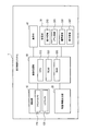
- FIG. 1 is a block diagram illustrating an example of the configuration of the display control system.
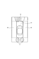
- FIG. 2 is a diagram illustrating an example of a bird's-eye view image displayed on the display unit, which is created by difference processing.
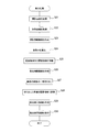
- FIG. 3 is a flowchart of the display control process.
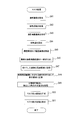
- FIG. 4 is a flowchart of difference processing in display control.
- FIG. 5 is a flowchart of mask processing in display control.
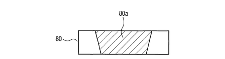
- FIG. 6 is a diagram illustrating an example of a difference image for subtracting the effect of headlamp light from a bird's-eye image of a photographed image of the front camera.
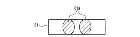
- FIG. 7 is a diagram illustrating an example of a difference image for subtracting the influence of light from the tail lamp from the bird's-eye view image of the rear camera.
- FIG. 1 is a block diagram illustrating an example of the configuration of the display control system.
- FIG. 2 is a diagram illustrating an example of a bird's-eye view image displayed on the display unit, which is created
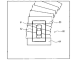
- FIG. 8 is a diagram for explaining a history image.
- FIG. 9 is a diagram illustrating an example of a bird's-eye view image in which light of a headlamp enlarged so as to be dragged appears.
- FIG. 10 is a diagram illustrating an example of a bird's-eye image displayed on the display unit, which is created by mask processing.
- the display control system 1 As shown in FIG. 1, the display control system 1 according to the present embodiment is mounted on a vehicle and includes a photographing unit 10, a movement information output unit 20, a storage unit 30, a display unit 40, and an image processing unit 50.
- the vehicle on which the display control system 1 is mounted is referred to as “own vehicle”.
- the photographing unit 10 includes a front camera 110 and a rear camera 120.
- the front camera 110 is an in-vehicle camera mounted on the front part of the host vehicle (for example, the upper center inside the windshield).
- the front camera 110 captures a predetermined range in front of the vehicle around the host vehicle.
- the rear camera 120 is an in-vehicle camera mounted on the rear part of the host vehicle (for example, the center in the vehicle width direction at the rear end of the host vehicle).
- the rear camera 120 captures a predetermined range behind the vehicle around the host vehicle.
- the front camera 110 and the rear camera 120 repeatedly shoot at a predetermined cycle (for example, 30 frames / second), and output the captured image to the image processing unit 50.
- the movement information output unit 20 is an apparatus configured to output movement information detected by sensors mounted on the host vehicle to the image processing unit 50.
- the movement information is information necessary for calculating the movement amount of the host vehicle.
- the amount of movement here means a change in the position and orientation of the host vehicle during a predetermined period.
- the movement information includes a wheel pulse counter, steering angle or yaw rate information, shift range information, and the like.
- the storage unit 30 is a device (memory) configured to be able to store information such as images in a predetermined area.
- the display unit 40 is a device (display) configured to be able to display an image.
- the display unit 40 is provided at a position where an occupant (for example, a driver) of the host vehicle can view the displayed image.
- the display unit 40 includes a touch panel for performing operations by directly touching the screen.
- the image processing unit 50 includes a microcomputer including a CPU 510, a ROM 520, a RAM 530, and the like.
- the CPU 510 executes display control processing including image processing (display control processing described later) including image processing in accordance with a program recorded in the ROM 520.
- the display control process is a process for displaying on the display unit 40 a bird's-eye view image centered on the host vehicle.
- the display control process includes the entire periphery of the host vehicle including the left and right sides of the host vehicle outside the shooting range of the shooting unit 10 in addition to the front and rear of the host vehicle that is the shooting range of the shooting unit 10.
- the bird's-eye view image referred to here is an image of a viewpoint looking down from directly above or obliquely below the host vehicle.
- a history portion that is a portion outside the shooting range of the shooting unit 10 is configured using the history image.
- the history portion 60 is located on the left and right sides of the icon 61 indicating the host vehicle.
- the history portion 60 is indicated by a dotted line, but this dotted line is not actually displayed on the display unit 40.
- the history image here is a bird's-eye image obtained by combining bird's-eye images that are sequentially created based on captured images while shifting the position based on the amount of movement of the host vehicle.
- the history image created in this way is created using, for example, a bird's-eye view image showing the irradiation light of the own vehicle, irradiation light that does not actually exist appears in the history portion 60.
- the displayed bird's-eye view image is enlarged so that the portion of the illumination light is dragged with the movement of the host vehicle. Therefore, in the display control process according to the present embodiment, image processing for preventing illumination light or the like from appearing in the history portion 60 is executed. Specifically, in the display control process, one of the difference process and the mask process is selectively executed.
- a bird's-eye image from which the irradiation light is removed is created by subtracting only the influence of the irradiation light from the bird's-eye image of the captured image in which the irradiation light is reflected.
- a history image is created based on the created bird's-eye view image. Thereby, in this process, irradiation light is prevented from appearing in the history portion.
- a history image is created based on a bird's-eye image of a photographed image in which irradiation light is reflected.
- the region where the irradiation light is displayed in the created history image is masked. Thereby, in this process, irradiation light is prevented from appearing in the history portion.
- the display control process is a process executed by the image processing unit 50 (CPU 510) included in the display control system 1 according to a predetermined program.
- the display control process is started when at least one of the head lamp and the tail lamp of the host vehicle is lit during a period in which the ignition switch of the host vehicle is on.
- the bird's-eye image of the photographed image is referred to as a “photographed bird's-eye image”.
- the image processing unit 50 determines whether there is a difference image (step S11).
- the difference image here is an image that is used in the difference process, and is an image that represents a change in the pixel value of the photographed bird's-eye view image due to the irradiation light of the host vehicle.
- the difference image is an image that represents a difference in pixel values of the captured bird's-eye view image based on the presence or absence of irradiation light of the host vehicle.
- the difference image is the following image. Even if the subject is the same image, the pixel value of the portion where the irradiation light is reflected changes depending on the presence or absence of the irradiation light.
- the pixel value here is a value for each pixel constituting the image, and is a luminance value in the present embodiment. For this reason, in two images that differ only in the presence or absence of irradiation light, the value of each pixel constituting an image in which irradiation light is not reflected is calculated from the value (pixel value) of each pixel in the image in which irradiation light is reflected. By subtracting, an image in which only the influence of irradiation light appears can be obtained.
- This image is a difference image. Thereby, in the display control processing according to the present embodiment, an image as if the irradiation light is not reflected can be generated by subtracting the difference image from the image where the irradiation light is reflected.
- headlamp light 70 is assumed as irradiation light reflected on the front camera 110.
- tail lamp light 71 is assumed as irradiation light reflected on the rear camera 120. Therefore, in this embodiment, for example, a difference image 80 as shown in FIG. 6 and a difference image 81 as shown in FIG. 7 are prepared in advance.
- the difference image 80 illustrated in FIG. 6 is an image for subtracting the influence of the light 70 of the headlamp from the bird's-eye view image captured by the front camera 110.
- the difference image 80 has a portion (a portion where the irradiation light appears) 80a where the light 70 of the headlamp appears.
- the difference image 81 has a portion 81a where the tail lamp light 71 appears (a portion where irradiation light appears) 81a.
- the two types of difference images 80 and 81 are stored in advance in a difference area 310 that is a predetermined storage area provided in the storage unit 30. Note that the two types of difference images 80 and 81 stored in the difference area 310 can be updated at a store (automobile dealer), a factory, or the like.
- the image processing unit 50 determines that there is a difference image when both of the two types of difference images 80 and 81 are stored in the difference area 310. On the other hand, the image processing unit 50 determines that there is no difference image when at least one of the two types of difference images 80 and 81 is not stored. As an example of a case where it is determined that there are no difference images 80 and 81, when the storage unit 30 is replaced (at the time of memory replacement), a new storage unit in which the two types of difference images 80 and 81 are not stored is used. The case where it exchanges is mentioned. If it is determined that there is a difference image (step S11: YES), the image processing unit 50 proceeds to the process of step S12. On the other hand, when determining that there is no difference image (step S11: NO), the image processing unit 50 proceeds to the process of step S16.
- the image processing unit 50 determines which one of the difference process and the mask process is selected (step S12).
- the user can select difference processing or mask processing. Specifically, the user can make a selection by operating a touch panel (user interface) of the display unit 40. Therefore, the image processing unit 50 performs the determination process in step S12 based on the user's operation status (selection result).
- step S12 difference process
- step S13 the image processing unit 50 proceeds to the process of step S13.
- the image processing unit 50 determines that the mask process is selected (step S12: mask process)
- the process proceeds to the process of step S16.
- the image processing unit 50 determines whether or not an operation for changing the difference amount between the image in which the irradiation light is reflected and each of the two types of difference images 80 and 81 has been performed by the user (step S13).
- the operation of changing the difference amount is performed in the following case, for example.
- the pixel value is not always subtracted by an appropriate amount.
- step S13 and step S14 are processes (difference amount adjustment process) for the user who has seen such an uncomfortable image to change the difference amount.
- the difference amount can be changed by the user operating the touch panel (user interface) of the display unit 40. Therefore, the image processing unit 50 performs the determination process in step S13 based on the user operation status (change result).
- the display of the image on the display unit 40 is performed by a difference process (a process in step S30 illustrated in FIG. 4) described later. Therefore, as will be described later, it is assumed that, in the processes of steps S12 to S17, which are normally repeatedly executed according to a predetermined cycle, it is not determined that an operation for changing the difference amount has been performed in the first process of step S13.
- step S13 When it is determined that an operation for changing the difference amount has been performed (step S13: YES), the image processing unit 50 proceeds to the process of step S14. On the other hand, if the image processing unit 50 determines that an operation for changing the difference amount has not been performed (step S13: NO), the process of step S14 is skipped, and the process proceeds to step S15.
- the image processing unit 50 changes the amount of difference between the image in which the irradiation light is reflected and the two types of difference images 80 and 81 (step S14). Specifically, the image processing unit 50 changes the pixel values of the two types of difference images 80 and 81.
- the image processing unit 50 changes the magnification of the pixel values of the two types of difference images 80 and 81 (changes to 0.9 times, 1.1 times, etc.), and only the portion where the irradiation light is reflected.
- the pixel value is substantially changed.
- the image processing unit 50 executes difference processing (processing shown in FIG. 4) (step S15). Details of the difference processing will be described later. After executing the process of step S15, the image processing unit 50 proceeds to the process of step S17.
- step S16 the image processing unit 50 executes mask processing (processing shown in FIG. 5) (step S16). This process is executed when a negative determination is made in the determination process of step S11 described above or when a mask process is determined in the determination process of step S12 described above. Details of the mask processing will be described later. After executing the process of step S16, the image processing unit 50 proceeds to the process of step S17.
- the image processing unit 50 determines whether or not the display control process end condition is satisfied (step S17). The image processing unit 50 determines that the end condition is satisfied when the ignition switch of the host vehicle is off, or when both the head lamp and the tail lamp are turned off.
- step S17: YES If the image processing unit 50 determines that the end condition is satisfied (step S17: YES), the image processing unit 50 ends the display control process. On the other hand, when it is determined that the end condition is not satisfied (step S17: NO), the image processing unit 50 returns to the determination of step S12 described above, and executes the processes after step S12 again.
- the image processing unit 50 acquires the latest captured image from each of the front camera 110 and the rear camera 120 (step S21).
- the image processing unit 50 acquires movement information from the movement information output unit 20 (step S22).
- the image processing unit 50 performs well-known image conversion (bird's-eye conversion) on the latest photographed image acquired in the process of step S21, and creates photographed bird's-eye images corresponding to the front camera 110 and the rear camera 120 respectively ( Step S23).
- the image processing unit 50 cuts out a part necessary for creating a display bird's-eye image from the created bird's-eye view image, and stores the cut-out image in a real area 320 that is a predetermined storage area provided in the storage unit 30. To do.
- the bird's-eye image captured by the front camera 110 is referred to as a “front-view bird's-eye image”
- the bird's-eye image captured by the rear camera 120 is referred to as a “rear-shot bird's-eye image”.
- the image processing unit 50 calculates the amount of movement of the host vehicle based on the movement information acquired in step S22 (step S24).
- the amount of movement of the host vehicle here means a change in the position and orientation of the host vehicle during a period (captured image acquisition interval) from the previous captured image acquisition timing to the current captured image acquisition timing.
- the image processing unit 50 moves the history image stored in the history area 330 based on the movement amount of the host vehicle calculated in the process of step S24 (step S25).
- the history area 330 here is a predetermined storage area provided in the storage unit 30 and stores a history image. As shown in FIG. 8, the history area 330 is designed to store not only the front and rear sides of the host vehicle but also a range that is slightly larger than the vehicle peripheral range 62 that is a range including the left and right sides of the host vehicle. ing. In FIG. 8, for convenience of explanation, an icon 61 indicating the host vehicle is shown. However, in the display control process according to the present embodiment, the icon 61 is not actually stored in the history area 330.
- the image processing unit 50 moves the history image 65 so that the position relative to the host vehicle changes in the process of step S25.
- the history image 65 is generated by being stored in the history area 330 in the process of step S28 described later. Therefore, in the first process of step S25, there is no movement target.
- the image processing unit 50 creates a removal bird's-eye view image (step S26).
- the removed bird's-eye view image is a bird's-eye view image from which the irradiation light reflected in the photographed bird's-eye view image is removed.
- the removal bird's-eye view image is created by calculating the difference between the photographed bird's-eye view image in which the irradiation light is reflected and each of the two types of difference images 80 and 81.
- the removed bird's-eye view image is created as an image representing the difference between the photographed bird's-eye view image in which the irradiation light is reflected and each of the two types of difference images 80 and 81.
- the removal bird's-eye view image is created as follows. Specifically, the image processing unit 50 creates a front-removed bird's-eye image in which the headlamp light 70 reflected in the image captured by the front camera 110 is removed from the front-shot bird's-eye image. In addition, the image processing unit 50 creates a rear-removed bird's-eye image in which the tail lamp light 71 reflected in the image captured by the rear camera 120 is removed from the rear-shot bird's-eye image.
- the determination as to whether or not the irradiation light is reflected in the front bird's-eye image and the rear bird's-eye image is performed based on on / off of the head lamp and tail lamp switches. Specifically, when the headlamp switch is on, it is determined that the headlamp light 70 is reflected in the front-view bird's-eye view image. On the other hand, when the headlamp switch is off, it is determined that the headlamp light 70 is not reflected in the front-view bird's-eye view image. The same applies to the determination of whether or not the irradiation light is reflected in the rear-view bird's-eye view image.
- the tail lamp switch when the tail lamp switch is on, it is determined that the tail lamp light 71 is reflected in the rear-view bird's-eye view image. On the other hand, when the tail lamp switch is off, it is determined that the tail lamp light 71 is not reflected in the rear-view bird's-eye view image.
- a removed bird's-eye image is created for an image that is determined to show the irradiated light among the front-shot bird's-eye image and the rear-shot bird's-eye image.
- a removal bird's-eye view image is not created for an image that is determined not to reflect irradiation light.
- the image processing unit 50 cuts out a part necessary for creating the display bird's-eye image from the latest removed bird's-eye image created in the process of step S26 (step S27). Further, the image processing unit 50 creates the display bird's-eye image from the latest photographed bird's-eye image for the image in which the removal bird's-eye image has not been created in the process of step S26 among the front-shot bird's-eye image and the rear-shot bird's-eye image. Cut out the necessary parts.
- the image processing unit 50 stores the image cut out in step S27 in the history area 330 (step S28). At this time, the image processing unit 50 stores the clipped image in the history area 330 as the history image 65 in a state where the history image 65 is not stored in the history area 330 (for example, the first processing). On the other hand, as illustrated in FIG. 8, the image processing unit 50 stores the history image 65 stored in the history area 330 in a state where the history image 65 is stored in the history area 330 (for example, the second and subsequent processes). The latest cut out images 63 and 64 are overwritten. As a result, the image processing unit 50 combines the history image 65 with the latest cut-out images 63 and 64 and updates the history image 65. The latest clipped image 63 is stored in a position corresponding to the front of the current host vehicle in the history area 330. In addition, the latest cut out image 64 is stored in a position corresponding to the current rear side of the host vehicle in the history area 330.
- processing for moving the history image 65 based on the amount of movement of the host vehicle and processing for overwriting the history image 65 after movement with the image cut out from the removed bird's-eye view image are executed. Is done.
- the removal history image is created as the history image 65 in the history area 330 by repeatedly executing these processes.
- a removal history image which is a bird's-eye view image synthesized by shifting the positions of the removal bird's-eye images that are sequentially created based on the movement amount of the host vehicle, is created in the history region 330 as the history image 65.
- one of the latest cut-out images 63 and 64 may be a photographed bird's-eye view image in which irradiation light is not reflected.
- the history image 65 created using only the removed bird's-eye image not only the history image 65 created using both the removed bird's-eye image and the photographed bird's-eye image that does not show the irradiation light is removed. This is called a history image.
- the removal history image is an image in which the influence of the irradiation light is reduced as compared with the history image 65 created based on the photographed bird's-eye view image on which the irradiation light is reflected.
- the image processing unit 50 creates a removal display image, which is a bird's-eye view image obtained by combining the removal history image and the latest photographed bird's-eye view image, as a display bird's-eye view image (step S29). At this time, the image processing unit 50 cuts out a portion included in the vehicle peripheral range 62 from the removal history image stored in the history area 330.
- the image processing unit 50 stores the cut image in a display area 340 that is a predetermined storage area provided in the storage unit 30.
- the image processing unit 50 stores the latest photographed bird's-eye image corresponding to each of the front camera 110 and the rear camera 120 read from the real area 320 in the display area 340 and overwrites the image cut out from the removal history image.
- the image processing unit 50 stores the icon 61 indicating the host vehicle in the display area 340 and overwrites the composite image of the removal history image and the latest photographed bird's-eye view image.
- a removal display image as shown in FIG. 2 is created by such an image composition process.
- the image processing unit 50 displays the removed display image stored in the display area 340 on the display unit 40 (step S30).
- the image processing unit 50 ends the difference process after executing the process of step S30.
- step S16 the mask process executed in step S16 described above will be described using the flowchart of FIG. Note that the processing of steps S41 to S45 in the mask processing is the same as the processing of steps S21 to S25 of the difference processing described above, and thus description thereof is omitted.
- the image processing unit 50 cuts out a part necessary for creating a display bird's-eye image from each of the latest front-shot bird's-eye image and rear-shot bird's-eye image created in the process of step S43 (step S46).
- the image processing unit 50 stores the cut-out image in the history area 330 (step S47). At this time, in a state where the history image 65 is stored in the history area 330, the image processing unit 50 overwrites the latest captured bird's-eye image with respect to the shooting history image as the history image 65 stored in the history area 330. To do. As a result, the shooting history image and the latest shooting bird's-eye view image are synthesized, and the shooting history image is updated.
- the imaging history image referred to here is a bird's-eye image obtained by combining the captured bird's-eye images sequentially generated in the process of step S43 while shifting the position based on the amount of movement of the host vehicle.
- the shooting history image is created as a history image 65 in the history area 330. Irradiated light is reflected in at least one of the front bird's-eye image and the rear bird's-eye image to be combined. Therefore, the shooting history image is enlarged so that the irradiation light is dragged with the movement of the host vehicle. Therefore, in the display control process according to the present embodiment, the shooting history image is updated by being combined with the latest shooting bird's-eye view image in the process of step S47.
- the image processing unit 50 cuts out a portion included in the vehicle surrounding area 62 from the shooting history image stored in the history area 330, and stores the cut out image in the display area 340 (step S48).
- the image processing unit 50 detects an area occupied by the irradiation light (hereinafter referred to as “light area”) in the shooting history portion 66 of the shooting history image shown in FIG. 9, and stores the light area at the time of detection (step S49). ).
- the shooting history portion 66 is a portion constituted by using a past shooting bird's-eye view image among the shooting history images stored in the display area 340.
- the shooting history portion 66 is a portion in which a shooting history image before combining with the latest shooting bird's-eye image appears in the shooting history image. That is, in the image processing unit 50, the light region is detected in the portion where the irradiation light magnified so as to be dragged by the processing in step S49 is reflected. In other words, in the process of step S49, the light region is detected for the portion where the irradiation light that appeared in the past photographed bird's-eye view appears.
- the shooting history portion 66 corresponds to a history portion of the displayed bird's-eye view image, as will be described later.
- detection of the light region is performed as follows. Specifically, the image processing unit 50 performs region division on a part of the shooting history portion 66 based on the hue and the luminance. The image processing unit 50 extracts two adjacent areas where the hue difference is equal to or smaller than a predetermined value and the luminance difference is equal to or larger than a predetermined value from among the plurality of divided areas. Of the two extracted regions, the image processing unit 50 sets a high luminance region as a light region and sets a low luminance region as a non-light region. The image processing unit 50 specifies a vector from the light region to the non-light region in the color information space as the color information of the light source.
- the image processing unit 50 divides the entire region of the shooting history portion 66 based on the hue and luminance. When the difference in hue between adjacent areas matches the hue of the light source within a predetermined range, the image processing unit 50 identifies an area with high luminance among the adjacent areas as an optical area.
- the irradiation light expanded so as to be dragged appears in the shooting history image.
- light 72 of the headlamp enlarged so as to be dragged appears at a position adjacent to the left and right sides of the icon 61 indicating the host vehicle in the photographing history portion 66.
- the light 72 of the headlamp is detected by executing the process of step S49.
- the shooting history portion 66 is completely filled with the past shooting history image.
- the process of step S49 is executed only once. It should be noted that whether or not the shooting history portion 66 (the history portion of the displayed bird's-eye view image) is completely filled with the past shooting history image (the past bird's-eye view image) is determined by, for example, the movement of the host vehicle after the display control process starts You may do it based on quantity.
- the image processing unit 50 creates a mask display image, which is a bird's-eye view image obtained by masking a predetermined region including the light region stored in the process of step S49, as a display bird's-eye view image in the photographing history portion 66 (step S50).
- the image processing unit 50 is displayed on the display unit 40 and painted with a predetermined area including a light area in a color (black or the like) that is known to be intentionally removed when visually recognized by the user.
- Mask a predetermined area.
- the process of step S49 is executed only once, and the light area at the time of execution is stored. Therefore, the image processing unit 50 repeatedly refers to the light area stored in the process of step S49 every time the process of step S50 is executed.
- the image processing unit 50 determines a mask region (masked region) in accordance with a predetermined condition so as to include the referenced light region.
- the image processing unit 50 masks the determined area.
- the condition here is a condition such that a rectangular area enlarged to a predetermined size is defined as a mask area with a minimum area including the optical area as a reference. That is, it is a condition that the mask area is uniquely determined with respect to the optical area.
- the mask area is fixed on the screen of the display unit 40 (does not change with the movement of the host vehicle).
- the reason why the mask area is fixed on the screen of the display unit 40 is that the mask area frequently changes on the screen of the display unit 40 by periodically executing the process of step S50. This is to avoid it.
- the icon 61 indicating the host vehicle is overwritten on the masked shooting history image.
- the shooting history image is not masked until the light area is stored in the process of step S49.
- the mask area is set larger than the minimum area including the irradiation light.
- the reason for setting the mask area is that, when the host vehicle is turned left and right (horizontal direction), the irradiation light that appears in the photographing history portion 66 moves only to the front and rear (vertical direction). This is because they appear at different positions.
- the mask region 90 is formed by masking a region where the length LR in the vertical direction (longitudinal direction) of the region is the same as the length LV before and after the host vehicle.
- the horizontal length WR (left and right width) of the mask region 90 is set to be larger than the left and right width WL of the light 72 of the headlamp shown in FIG.
- the image processing unit 50 displays the mask display image created in step S50 on the display unit 40 (step S51).
- the image processing unit 50 ends the mask process after executing the process of step S51.
- the image processing unit 50 creates a removed bird's-eye image that is a bird's-eye image from which the irradiation light of the vehicle is removed. Specifically, the image processing unit 50 calculates a difference between the photographed bird's-eye image on which the irradiation light is reflected and the two types of difference images 80 and 81, and creates a removal bird's-eye image as an image representing the difference. The image processing unit 50 creates a removal display image to be displayed on the display unit 40 as a display bird's-eye image using a removal history image created based on the sequentially created removal bird's-eye image.
- the image processing unit 50 uses the removal history image created based on the removed bird's-eye image from which the irradiation light has been removed, instead of the history image 65 created based on the captured bird's-eye image in which the irradiation light is reflected.
- the display bird's-eye view image to be displayed on the display unit 40 is generated.
- the image processing unit 50 displays the created mask display image on the display unit 40. Therefore, in the display control device according to the present embodiment, it is possible to suppress the irradiation light of the vehicle from expanding on the image of the display unit 40.
- the image processing unit 50 changes the difference amount between the captured bird's-eye view image and the two types of difference images 80 and 81 based on an operation by the user.
- the difference amount is adjusted to an appropriate amount. it can.
- the image processing unit 50 performs mask processing instead of difference processing in display control.
- the image processing unit 50 creates a shooting history image based on the sequentially taken bird's-eye images.
- the image processing unit 50 detects a light area in the shooting history portion 66 in which the shooting history image before the combination appears in the bird's-eye view image obtained by combining the shooting history image and the latest shooting bird's-eye view image.
- the image processing unit 50 creates a mask display image, which is a bird's-eye image from which irradiation light has been removed, as a display bird's-eye image by masking a predetermined region including the detected light region.
- the image processing unit 50 displays the created mask display image on the display unit 40.
- a predetermined area including the light area is uniformly painted with black or the like (a color that can be intentionally removed) regardless of the brightness around the host vehicle. This eliminates the need for the user to adjust the amount of difference as performed in the difference process.
- the display unit 40 corresponds to a display device
- the image processing unit 50 corresponds to a display control device
- the front camera 110 and the rear camera 120 correspond to an in-vehicle camera.
- the headlamp light 70 and the tail lamp light 71 correspond to the irradiation light of the vehicle
- the headlamp light 72 enlarged so as to be dragged corresponds to the removal target
- two types of difference images 80 and 81 are obtained. This corresponds to the second difference image.
- the process of step S14 is corresponded to the process which implement
- steps S21 and S41 correspond to a process for realizing the acquisition unit
- steps S23 and S43 correspond to a process for realizing the first image creating unit
- steps S24 and S44 correspond to a process for realizing the calculation unit
- the process in step S26 corresponds to a process for realizing the second image creating unit.
- the processes in steps S25, S27, and S28 correspond to the process for realizing the removal history creating unit
- the process in step S29 corresponds to the process for realizing the removal display creating unit
- the process in step S30 is performed for the removal display processing unit. This corresponds to the process to be realized.
- steps S45, S46, and S47 correspond to the process for realizing the photographing history creating unit
- the process in step S50 corresponds to the process for realizing the mask display creating unit
- the process in step S51 uses the mask display processing unit. This corresponds to the process to be realized.
- the image processing unit 50 calculates the difference between the photographed bird's-eye view image and the two types of difference images 80 and 81 after performing bird's-eye conversion on the photographed image.
- the timing for calculating the difference is not limited to this.
- the image processing unit 50 may calculate the difference before performing the bird's eye conversion.
- the image processing unit 50 may calculate a difference between a captured image in which the irradiation light is reflected and a difference image that is an image representing a change in the pixel value of the captured image due to the irradiation light.
- the image processing unit 50 may calculate a difference between a captured image in which the irradiation light is reflected and a difference image that is an image representing a difference between pixel values of the captured image depending on the presence or absence of the irradiation light.
- the removal bird's-eye view image may be created as an image obtained by bird's-eye conversion of an image representing the difference between the captured image in which the irradiation light is reflected and the difference image.
- the image processing unit 50 uses the two types of difference images 80 and 81 stored in advance in the storage unit 30 when calculating the difference from the captured image in which the irradiation light is reflected.
- An example is shown.
- the difference image to be used is not limited to this.
- the image processing unit 50 may generate a difference image when driving the host vehicle, and use the generated difference image.
- the image processing unit 50 includes two photographed images (for example, photographed images immediately before and immediately after the headlamps are turned on) that are substantially the same except for the presence or absence of irradiation light, or their bird's-eye view images.
- An image representing the difference may be used as the difference image.
- the light 70 of the headlamp and the light 71 of the tail lamp are exemplified as the irradiation light of the vehicle.
- the irradiation light of the vehicle is not limited to this.
- the irradiation light may be light from a brake lamp or the like.
- the mask region 90 is set larger than the minimum region including the irradiation light in the mask processing in the display control.
- the mask area is not limited to this.
- the mask region may be set as a region including only irradiation light.
- the image processing unit 50 detects and stores the light region only once, and masks the region determined according to a predetermined condition so as to include the stored light region, thereby displaying the mask.
- An example of creating an image is shown.
- the method for creating the mask display image is not limited to this.
- the image processing unit 50 detects a light region in the latest photographed bird's-eye view image and masks a region including the detected light region. Then, the image processing unit 50 creates a history image using the latest masked bird's-eye image that has been masked, and overwrites the latest photographed bird's-eye image on a portion included in the vehicle peripheral range 62 cut out from the created history image.
- the image processing unit 50 may create a mask display image by such a method. That is, the image processing unit 50 may create a display bird's-eye view image in which the light area is replaced with the mask area.
- a light area is detected for each past photographed bird's-eye image that appears as the vehicle moves in the history portion of the displayed bird's-eye image displayed on the display unit 40, and includes the light area.
- Mask the area.
- the display control process when the history portion of the displayed bird's-eye view image is completely filled with the past photographed bird's-eye view image on the image of the display unit 40, the mask area at that time may be maintained. That is, in the above-described embodiment, the masked display bird's-eye image is not displayed until the shooting history portion 66 of the shooting history image is completely filled with the past shooting history image. However, in the display control process described above, the masked display bird's-eye view image may be displayed even before the shooting history image is completely filled.
- the image processing unit 50 creates a mask display image by masking a predetermined region without detecting a light region (regardless of how the irradiation light appears in the history portion of the display bird's-eye view image). Also good.
- the irradiation light of the host vehicle is exemplified as the removal target to be removed by masking, but the removal target is not limited to this.
- the removal target may be a shadow of the host vehicle.
- the image processing unit 50 selects and executes either one of the difference processing and the mask processing.
- the process to be executed is not limited to this.
- the image processing unit 50 may execute only one of the difference process and the mask process.
- the image processing unit 50 determines that there is a difference image only when both of the two types of difference images 80 and 81 are stored in the process of step S11. It is shown. However, the criterion is not limited to this. For example, in addition to the case where both of the two types of difference images 80 and 81 are stored, the image processing unit 50 stores only one of the two types of difference images 80 and 81. Alternatively, it may be determined that there is a difference image. In this case, the image processing unit 50 may execute a difference process for subtracting the influence of the lamp determined to have a corresponding difference image from the head lamp light 70 and the tail lamp light 71.
- the camera mounting status is not limited to this.
- the configuration may be such that only one of the front camera 110 and the rear camera 120 is mounted on the host vehicle.
- the vehicle may have one camera on each of the left and right sides of the vehicle, and a total of four cameras may be mounted.
- the history image synthesis may not be performed.
- history image synthesis may be performed in order to fill a bird's-eye view image of a photographed image by the camera in which the abnormality has occurred.
- the display unit 40 which is a display provided in the host vehicle is illustrated as the display device.
- the display device is not limited to this.
- Other examples of the display device include HUD (head-up display).
- part or all of the processing executed by the image processing unit 50 is not limited to the configuration realized by software such as a program.
- a configuration realized by hardware such as one or a plurality of ICs may be used.
- the functions of one component in the above embodiment may be distributed as a plurality of components.
- the functions of the plurality of components in the above embodiment may be integrated into one component.
- at least a part of the configuration in the above embodiment may be added to or replaced with the configuration in the other embodiment. Note that the embodiment of the present disclosure covers all aspects included in the technical idea specified only by the wording described in the claims.
- a system including the image processing unit 50 as a component, a program for causing a computer to function as the image processing unit 50, a recording medium such as a semiconductor memory in which the program is recorded, a difference or masking is performed. For example, the irradiation light reflected in the image or the photographed bird's-eye view image is removed.
- DESCRIPTION OF SYMBOLS 1 ... Display control system, 10 ... Image pick-up part, 20 ... Movement information output part, 30 ... Memory
Landscapes
- Engineering & Computer Science (AREA)
- Multimedia (AREA)
- Signal Processing (AREA)
- Physics & Mathematics (AREA)
- General Physics & Mathematics (AREA)
- Theoretical Computer Science (AREA)
- Mechanical Engineering (AREA)
- Closed-Circuit Television Systems (AREA)
- Image Processing (AREA)
- Traffic Control Systems (AREA)
- Image Analysis (AREA)
- Controls And Circuits For Display Device (AREA)
Abstract
画像処理部は、撮影画像の鳥瞰画像である撮影鳥瞰画像であって、撮影画像に映った照射光が除去された鳥瞰画像である除去鳥瞰画像を作成する(S26)。除去鳥瞰画像は、照射光が映った撮影鳥瞰画像と、自車両の照射光による撮影鳥瞰画像の画素値の変化を表す画像である差分用画像と、の差分を表す鳥瞰画像として作成される。画像処理部は、除去鳥瞰画像を、自車両の移動量に基づいて、位置をずらしながら合成した鳥瞰画像である除去履歴画像を作成する(S25,S27,S28)。画像処理部は、除去履歴画像と、最新の撮影鳥瞰画像と、を合成した鳥瞰画像である除去表示画像を作成し(S29)、除去表示画像を表示部に表示させる(S30)。
Description
本開示は、表示制御装置及び表示制御方法に関する。
近年では、車両に搭載された車載カメラで車両の周辺における所定の範囲を繰り返し撮影し、撮影画像を車両の上方から見下ろす視点の鳥瞰画像に変換し、鳥瞰画像を車両内の表示部に表示させる技術が知られている。
このような技術において、最新の撮影画像の鳥瞰画像と過去の撮影画像の鳥瞰画像とを合成した画像を表示部に表示することで、車両の周辺の画像表示範囲を広げる履歴画像合成技術がある。例えば特許文献1には、この履歴画像合成技術において、表示部の画像における自車両の影が車両の移動とともに拡大してしまうことを抑制する技術が開示されている。
特許文献1に記載の技術では、車載カメラが車両の後方を撮影するリアカメラであり、リアル領域と履歴領域とが記憶部(所定の記憶領域)に設けられる。リアルA領域は、車両の後方を前後方向に分割したうちの車両からより離れた方の所定の範囲の画像を保存するための領域である。リアルB領域は、車両により近い方の所定の範囲の画像を保存するための領域である。履歴C領域は、車載カメラの撮影範囲外の鳥瞰画像を保存するための領域である。
履歴B領域は、リアルB領域と同じ範囲の鳥瞰画像を保存するための領域である。リアルB領域に影がある場合には、履歴B領域内の鳥瞰画像に、現在の車両周辺の配置が反映されるように、履歴B領域内に鳥瞰画像を構成する。具体的には、車両の移動量に基づいて、リアルA領域内に保存された鳥瞰画像を用いて履歴B領域内に鳥瞰画像を構成する。さらに、車両の移動量に基づいて、履歴B領域内に保存された鳥瞰画像を用いて履歴C領域内に鳥瞰画像を構成する。
このように、リアルB領域に影がある場合は、影のない可能性が高いリアルA領域の鳥瞰画像に基づいて構成された履歴B領域の鳥瞰画像を用いて履歴画像合成を行う。これにより、特許文献1に記載の技術では、表示画像において、車両の移動とともに自車両の影が拡大してしまうことが抑制される。
履歴画像合成技術において、前述した拡大の問題は、車両の影に限らず、車両の照射光についても起こり得る。車両の照射光としては、ヘッドランプの照射光やテールランプの照射光等が挙げられる。
このような照射光は、影に比べてより遠方にまで及ぶ。そのため、例えば前述した特許文献1に記載のような構成では、車両の照射光がリアルB領域の鳥瞰画像だけでなく、リアルA領域の鳥瞰画像にも映る可能性がある。この場合には、リアルA領域の鳥瞰画像に基づいて構成された履歴B領域の鳥瞰画像を用いて履歴画像合成を行っても、表示画像において、車両の移動とともに車両の照射光が拡大してしまう。
本開示は、履歴画像合成技術において、表示部の画像上で車両の照射光の拡大を抑制することを目的とする。
本開示の技術の一態様は、車両の周辺における所定の範囲の撮影画像を車両に搭載された表示部(40)に表示する表示制御装置(50)であって、取得部(S21,S41)と、第1の画像作成部(S23,S43)と、第2の画像作成部(S26)と、算出部(S24,S44)と、除去履歴作成部(S25,S27,S28)と、除去表示作成部(S29)と、除去表示処理部(S30)と、を備える。取得部は、車両に搭載された車載カメラ(110,120)から撮影画像を繰り返し取得する。第1の画像作成部は、撮影画像の鳥瞰画像である撮影鳥瞰画像を逐次作成する。第2の画像作成部は、撮影画像の鳥瞰画像であって、撮影画像に映った車両の照射光(70,71)が除去された鳥瞰画像である除去鳥瞰画像を逐次作成する。算出部は、車両の移動量を算出する。除去履歴作成部は、第2の画像作成部により逐次作成される除去鳥瞰画像を、移動量に基づいて、位置をずらしながら合成した鳥瞰画像である除去履歴画像を作成する。除去表示作成部は、除去履歴画像と最新の撮影鳥瞰画像とを合成した鳥瞰画像である除去表示画像を作成する。除去表示処理部は、除去表示画像を表示部に表示させる。第2の画像作成部は、次のような鳥瞰画像のうちの少なくとも一方を除去鳥瞰画像として作成する。具体的には、照射光が映った撮影画像と、照射光による撮影画像の画素値の変化を表す画像である第1の差分用画像と、の差分を表す画像を鳥瞰変換した鳥瞰画像を作成する。また、照射光が映った撮影鳥瞰画像と、照射光による撮影鳥瞰画像の画素値の変化を表す画像である第2の差分用画像(80,81)と、の差分を表す鳥瞰画像を作成する。第2の画像作成部は、このような鳥瞰画像のうちの少なくとも一方を除去鳥瞰画像として作成する。
また、本開示の技術の別態様は、車両の周辺における所定の範囲の撮影画像を車両内の表示部(40)に表示する表示制御装置(50)における表示制御方法であって、取得工程(S21,S41)と、第1の画像作成工程(S23,S43)と、第2の画像作成工程(S26)と、算出工程(S24,S44)と、除去履歴作成工程(S25,S27,S28)と、除去表示作成工程(S29)と、除去表示処理工程(S30)と、を含む。取得工程は、車両に搭載された車載カメラ(110,120)から撮影画像を繰り返し取得する。第1の画像作成工程は、撮影画像の鳥瞰画像である撮影鳥瞰画像を逐次作成する。第2の画像作成工程は、撮影画像の鳥瞰画像であって、撮影画像に映った車両の照射光(70,71)が除去された鳥瞰画像である除去鳥瞰画像を逐次作成する。算出工程は、車両の移動量を算出する。除去履歴作成工程は、第2の画像作成工程により逐次作成される除去鳥瞰画像を、移動量に基づいて、位置をずらしながら合成した鳥瞰画像である除去履歴画像を作成する。除去表示作成工程は、除去履歴画像と最新の撮影鳥瞰画像とを合成した鳥瞰画像である除去表示画像を作成する。除去表示処理工程は、除去表示画像を表示部に表示させる。第2の画像作成工程は、次のような鳥瞰画像のうちの少なくとも一方を除去鳥瞰画像として作成する。具体的には、照射光が映った撮影画像と、照射光による撮影画像の画素値の変化を表す画像である第1の差分用画像と、の差分を表す画像を鳥瞰変換した鳥瞰画像を作成する。また、照射光が映った撮影鳥瞰画像と、照射光による撮影鳥瞰画像の画素値の変化を表す画像である第2の差分用画像(80,81)と、の差分を表す鳥瞰画像を作成する。第2の画像作成工程は、このような鳥瞰画像のうちの少なくとも一方を除去鳥瞰画像として作成する。
このような構成によれば、表示部の画像上で車両の照射光が拡大することを抑制できる。すなわち、仮に、車両の照射光が映った撮影鳥瞰画像を、車両の移動量に基づいて、位置をずらしながら合成した鳥瞰画像を作成する場合には、その鳥瞰画像における車両の照射光が車両の移動とともに拡大される。したがって、そのような鳥瞰画像に最新の撮影鳥瞰画像を合成して表示部に表示すると、表示画像において、車両の移動とともに車両の照射光が拡大してしまう。
これに対して、本開示の技術では、車両の照射光が除去された除去鳥瞰画像を、車両の移動量に基づいて、位置をずらしながら合成した除去履歴画像を作成し、除去履歴画像を用いて除去表示画像を作成する。このような構成によれば、表示部の画像上で車両の照射光が拡大することを抑制できる。
なお、本項目欄及び請求の範囲に記載した括弧内の符号は、本開示の技術の一態様として後述する実施形態に記載の具体的手段との対応関係を示すものである。よって、本開示の技術的範囲を限定するものではない。
以下、図面を参照しながら、本開示の技術の一態様を実施するための形態について説明する。
[1.構成]
図1に示すように、本実施形態に係る表示制御システム1は、車両に搭載され、撮影部10、移動情報出力部20、記憶部30、表示部40及び、画像処理部50を備える。以下では、表示制御システム1が搭載された車両を「自車両」という。
[1.構成]
図1に示すように、本実施形態に係る表示制御システム1は、車両に搭載され、撮影部10、移動情報出力部20、記憶部30、表示部40及び、画像処理部50を備える。以下では、表示制御システム1が搭載された車両を「自車両」という。
撮影部10は、フロントカメラ110及びリアカメラ120を備える。
フロントカメラ110は、自車両の前部(例えばフロントガラス内側の上部中央)に搭載された車載カメラである。フロントカメラ110は、自車両周辺における車両前方の所定の範囲を撮影する。
フロントカメラ110は、自車両の前部(例えばフロントガラス内側の上部中央)に搭載された車載カメラである。フロントカメラ110は、自車両周辺における車両前方の所定の範囲を撮影する。
リアカメラ120は、自車両の後部(例えば自車両の後端における車幅方向の中央)に搭載された車載カメラである。リアカメラ120は、自車両周辺における車両後方の所定の範囲を撮影する。
フロントカメラ110及びリアカメラ120は、所定の周期(例えば30フレーム/秒)で繰り返し撮影を行い、撮影画像を画像処理部50へ出力する。
移動情報出力部20は、自車両に搭載されたセンサ類により検出された移動情報を、画像処理部50へ出力するように構成された装置である。本実施形態において、移動情報とは、自車両の移動量を算出するために必要な情報である。ここでいう移動量とは、所定の期間における自車両の位置及び向きの変化を意味する。移動情報には、車輪のパルスカウンタ、ステアリング角又はヨーレートの情報、シフトレンジの情報等が含まれる。
移動情報出力部20は、自車両に搭載されたセンサ類により検出された移動情報を、画像処理部50へ出力するように構成された装置である。本実施形態において、移動情報とは、自車両の移動量を算出するために必要な情報である。ここでいう移動量とは、所定の期間における自車両の位置及び向きの変化を意味する。移動情報には、車輪のパルスカウンタ、ステアリング角又はヨーレートの情報、シフトレンジの情報等が含まれる。
記憶部30は、画像等の情報を所定の領域に記憶可能に構成された装置(メモリ)である。
表示部40は、画像を表示可能に構成された装置(ディスプレイ)である。表示部40は、表示された画像を、自車両の乗員(例えば運転者)が視認可能な位置に設けられる。表示部40は、画面に直接触れて操作を行うためのタッチパネルを備える。
表示部40は、画像を表示可能に構成された装置(ディスプレイ)である。表示部40は、表示された画像を、自車両の乗員(例えば運転者)が視認可能な位置に設けられる。表示部40は、画面に直接触れて操作を行うためのタッチパネルを備える。
画像処理部50は、CPU510、ROM520、RAM530等で構成されるマイクロコンピュータを備える。画像処理部50は、CPU510が、ROM520に記録されているプログラムに従い、画像処理を含む表示制御処理等(後述する表示制御処理)を実行する。
[2.処理]
以降に、画像処理部50が実行する表示制御処理について説明する。
まず、表示制御処理の概要について説明する。表示制御処理は、自車両を中心とする鳥瞰画像を、表示部40に表示するための処理である。具体的には、表示制御処理は、撮影部10の撮影範囲である自車両の前方及び後方に加え、撮影部10の撮影範囲外である自車両の左右の側方を含む自車両の全周囲を表す鳥瞰画像を、表示部40に表示するための処理である。ここでいう鳥瞰画像とは、自車両の上方から真下又は斜め下に見下ろす視点の画像である。表示部40に表示される鳥瞰画像である表示鳥瞰画像のうち、撮影部10の撮影範囲外の部分である履歴部分は、履歴画像を用いて構成される。図2の表示鳥瞰画像に示すように、履歴部分60は、自車両を示すアイコン61の左右の側方に位置している。なお、図2では、説明の便宜上、履歴部分60を点線で示しているが、この点線は、実際には表示部40に表示されない。ここでいう履歴画像とは、撮影画像に基づき逐次作成される鳥瞰画像を、自車両の移動量に基づいて、位置をずらしながら合成した鳥瞰画像である。
以降に、画像処理部50が実行する表示制御処理について説明する。
まず、表示制御処理の概要について説明する。表示制御処理は、自車両を中心とする鳥瞰画像を、表示部40に表示するための処理である。具体的には、表示制御処理は、撮影部10の撮影範囲である自車両の前方及び後方に加え、撮影部10の撮影範囲外である自車両の左右の側方を含む自車両の全周囲を表す鳥瞰画像を、表示部40に表示するための処理である。ここでいう鳥瞰画像とは、自車両の上方から真下又は斜め下に見下ろす視点の画像である。表示部40に表示される鳥瞰画像である表示鳥瞰画像のうち、撮影部10の撮影範囲外の部分である履歴部分は、履歴画像を用いて構成される。図2の表示鳥瞰画像に示すように、履歴部分60は、自車両を示すアイコン61の左右の側方に位置している。なお、図2では、説明の便宜上、履歴部分60を点線で示しているが、この点線は、実際には表示部40に表示されない。ここでいう履歴画像とは、撮影画像に基づき逐次作成される鳥瞰画像を、自車両の移動量に基づいて、位置をずらしながら合成した鳥瞰画像である。
このように作成される履歴画像は、例えば自車両の照射光が映った鳥瞰画像を用いて作成されると、実際には存在しない照射光が履歴部分60に現れてしまう。その結果、表示鳥瞰画像では、自車両の移動に伴い、照明光の部分が引きずられるように拡大してしまう。そこで、本実施形態に係る表示制御処理では、照明光等が履歴部分60に現れないようにするための画像処理が実行される。具体的には、表示制御処理では、差分処理及びマスク処理のうちの一方が選択的に実行される。
差分処理では、照射光が映った撮影画像の鳥瞰画像から照射光の影響のみを差し引いて、照射光が除去された鳥瞰画像を作成する。そして、本処理では、作成した鳥瞰画像に基づき履歴画像を作成する。これにより、本処理では、照射光が履歴部分に現れないようにする。
一方、マスク処理では、照射光が映った撮影画像の鳥瞰画像に基づき履歴画像を作成する。そして、本処理では、作成した履歴画像における照射光が表示された領域をマスクする。これにより、本処理では、照射光が履歴部分に現れないようにする。
[2.1.表示制御処理]
以降に、表示制御処理の詳細について図3~図5を用いて説明する。表示制御処理は、上述したように、表示制御システム1が備える画像処理部50(CPU510)が所定のプログラムに従って実行する処理である。また、表示制御処理は、自車両のイグニッションスイッチがオンである期間において、自車両のヘッドランプ及びテールランプのうちの少なくとも一方が点灯されることにより開始される。なお、以降の説明では、撮影画像の鳥瞰画像を「撮影鳥瞰画像」という。
以降に、表示制御処理の詳細について図3~図5を用いて説明する。表示制御処理は、上述したように、表示制御システム1が備える画像処理部50(CPU510)が所定のプログラムに従って実行する処理である。また、表示制御処理は、自車両のイグニッションスイッチがオンである期間において、自車両のヘッドランプ及びテールランプのうちの少なくとも一方が点灯されることにより開始される。なお、以降の説明では、撮影画像の鳥瞰画像を「撮影鳥瞰画像」という。
画像処理部50は、差分用画像があるか否かを判定する(ステップS11)。ここでいう差分用画像とは、差分処理で使用される画像であって、自車両の照射光による撮影鳥瞰画像の画素値の変化を表す画像である。換言すれば、差分用画像とは、自車両の照射光の有無による撮影鳥瞰画像の画素値の差分を表す画像である。
具体的には、差分用画像とは、次のような画像である。撮影対象が同一の画像であっても、照射光の有無により照射光が映る部分の画素値は変化する。ここでいう画素値とは、画像を構成する画素ごとの値であり、本実施形態では輝度値である。このため、照射光の有無のみが異なる2つの画像において、照射光が映っている画像を構成する各画素の値(画素値)から、照射光が映っていない画像を構成する各画素の値を差し引くことで、照射光の影響のみが現れた画像が得られる。この画像が差分用画像である。これにより、本実施形態に係る表示制御処理では、照射光が映っている画像から差分用画像を差し引くことで、照射光が映っていないかのような画像を生成できる。
本実施形態では、図2に示すように、フロントカメラ110に映る照射光として、ヘッドランプの光70が想定される。また、本実施形態では、リアカメラ120に映る照射光として、テールランプの光71が想定される。このため、本実施形態では、例えば図6に示すような差分用画像80と、図7に示すような差分用画像81と、が予め用意されている。具体的には、図6に示す差分用画像80は、フロントカメラ110の撮影鳥瞰画像からヘッドランプの光70の影響を差し引くための画像である。差分用画像80は、ヘッドランプの光70が現れている部分(照射光が表れている部分)80aを有している。また、図7に示す差分用画像81は、リアカメラ120の撮影鳥瞰画像からテールランプの光71の影響を差し引くための画像である。差分用画像81は、テールランプの光71が現れている部分(照射光が表れている部分)81aを有している。
2種類の差分用画像80,81は、記憶部30に設けられた所定の記憶領域である差分領域310に予め記憶されている。なお、差分領域310に記憶された2種類の差分用画像80,81は、販売店(自動車ディーラー)や工場等で更新できる。
画像処理部50は、差分領域310に上記2種類の差分用画像80,81の両方が記憶されている場合に、差分用画像があると判定する。一方、画像処理部50は、2種類の差分用画像80,81のうちの少なくとも一方が記憶されていない場合に、差分用画像がないと判定する。差分用画像80,81がないと判定される場合の一例としては、記憶部30を交換するときに(メモリ交換時に)、2種類の差分用画像80,81が記憶されていない新しい記憶部に交換した場合等が挙げられる。画像処理部50は、差分用画像があると判定した場合(ステップS11:YES)、ステップS12の処理へ移行する。一方、画像処理部50は、差分用画像がないと判定した場合(ステップS11:NO)、ステップS16の処理へ移行する。
画像処理部50は、差分処理及びマスク処理のうちのどちらの処理が選択されているかを判定する(ステップS12)。本実施形態では、ユーザが、差分処理又はマスク処理を選択できる。具体的には、ユーザは、表示部40のタッチパネル(ユーザインタフェース)を操作することで選択できる。よって、画像処理部50は、ユーザの操作状況(選択結果)に基づいて、ステップS12の判定処理を行う。画像処理部50は、差分処理が選択されていると判定した場合(ステップS12:差分処理)、ステップS13の処理へ移行する。一方、画像処理部50は、マスク処理が選択されていると判定した場合(ステップS12:マスク処理)、ステップS16の処理へ移行する。
画像処理部50は、照射光が映った画像と2種類の差分用画像80,81それぞれとの差分量を変更する操作が、ユーザにより行われたか否かを判定する(ステップS13)。差分量を変更する操作が行われるのは、例えば次のような場合である。照射光が映った画像と2種類の差分用画像80,81それぞれとの差分を算出する際、常に適切な量だけ画素値が差し引かれるとは限らない。具体的には、差分用画像80,81を用いて差分を算出する場合、自車両周辺の明るさによっては、照射光が映った画像から画素値を差し引く量が多かったり(引きすぎたり)、画素値を差し引く量が少なかったり(引き足りなかったり)する場合がある。このような場合には、画素値が適切ではない画像(違和感のある画像)が表示部40に表示されてしまう。ステップS13及び後述するステップS14の処理は、このような違和感のある画像を見たユーザが、差分量を変更するための処理(差分量調整処理)である。本実施形態に係る表示制御処理では、ユーザが表示部40のタッチパネル(ユーザインタフェース)を操作することで、差分量を変更できる。よって、画像処理部50は、ユーザの操作状況(変更結果)に基づいて、ステップS13の判定処理を行う。
なお、表示部40への画像の表示は、後述する差分処理(図4に示すステップS30の処理)で行われる。そのため、後述するように、通常、所定周期に従って繰り返し実行されるステップS12~S17の処理において、第1回目のステップS13の処理では、差分量を変更する操作が行われたと判定されないことが想定される。
画像処理部50は、差分量を変更する操作が行われたと判定した場合(ステップS13:YES)、ステップS14の処理へ移行する。一方、画像処理部50は、差分量を変更する操作が行われていないと判定した場合(ステップS13:NO)、ステップS14の処理をスキップし、ステップS15の処理へ移行する。
画像処理部50は、照射光が映った画像と2種類の差分用画像80,81それぞれとの差分量を変更する(ステップS14)。具体的には、画像処理部50は、2種類の差分用画像80,81それぞれの画素値を変更する。2種類の差分用画像80,81では、照射光が現れている部分80a,81aの画素値は0より大きく、それ以外の部分の画素値は0である。よって、画像処理部50は、2種類の差分用画像80,81の画素値の倍率をそれぞれ変更(0.9倍や1.1倍等に変更)して、照射光の映った部分のみの画素値を実質的に変更する。これにより、本実施形態に係る表示制御処理では、画素値が変更された2種類の差分用画像80,81を用いることで、照射光が映った画像と2種類の差分用画像80,81それぞれとの差分量が変更される。
画像処理部50は、照射光が映った画像と2種類の差分用画像80,81それぞれとの差分量を変更する(ステップS14)。具体的には、画像処理部50は、2種類の差分用画像80,81それぞれの画素値を変更する。2種類の差分用画像80,81では、照射光が現れている部分80a,81aの画素値は0より大きく、それ以外の部分の画素値は0である。よって、画像処理部50は、2種類の差分用画像80,81の画素値の倍率をそれぞれ変更(0.9倍や1.1倍等に変更)して、照射光の映った部分のみの画素値を実質的に変更する。これにより、本実施形態に係る表示制御処理では、画素値が変更された2種類の差分用画像80,81を用いることで、照射光が映った画像と2種類の差分用画像80,81それぞれとの差分量が変更される。
画像処理部50は、差分処理(図4に示す処理)を実行する(ステップS15)。差分処理の詳細については後述する。
画像処理部50は、ステップS15の処理を実行後、ステップS17の処理へ移行する。
画像処理部50は、ステップS15の処理を実行後、ステップS17の処理へ移行する。
また、画像処理部50は、マスク処理(図5に示す処理)を実行する(ステップS16)。本処理は、前述したステップS11の判定処理で否定判定された場合や、前述したステップS12の判定処理でマスク処理と判定された場合に実行される。マスク処理の詳細については後述する。画像処理部50は、ステップS16の処理を実行後、ステップS17の処理へ移行する。
画像処理部50は、表示制御処理の終了条件が成立したか否かを判定する(ステップS17)。画像処理部50は、自車両のイグニッションスイッチがオフである場合や、ヘッドランプ及びテールランプの両方が消灯している場合に、終了条件が成立したと判定する。
画像処理部50は、終了条件が成立したと判定した場合(ステップS17:YES)、表示制御処理を終了する。一方、画像処理部50は、終了条件が成立していないと判定した場合(ステップS17:NO)、前述したステップS12の判定へ戻り、ステップS12以降の処理を再び実行する。
[2.2.差分処理]
次に、上述したステップS15で実行される差分処理について図4を用いて説明する。
画像処理部50は、フロントカメラ110及びリアカメラ120のそれぞれから最新の撮影画像を取得する(ステップS21)。
次に、上述したステップS15で実行される差分処理について図4を用いて説明する。
画像処理部50は、フロントカメラ110及びリアカメラ120のそれぞれから最新の撮影画像を取得する(ステップS21)。
画像処理部50は、移動情報出力部20から移動情報を取得する(ステップS22)。
画像処理部50は、ステップS21の処理で取得した最新の撮影画像に対して周知の画像変換(鳥瞰変換)を施して、フロントカメラ110及びリアカメラ120それぞれに対応する撮影鳥瞰画像を作成する(ステップS23)。このとき画像処理部50は、作成した撮影鳥瞰画像から表示鳥瞰画像の作成に必要となる部分を切り出し、切り出した画像を、記憶部30に設けられた所定の記憶領域であるリアル領域320に記憶する。なお、以下では、フロントカメラ110の撮影鳥瞰画像を「前方撮影鳥瞰画像」といい、リアカメラ120の撮影鳥瞰画像を「後方撮影鳥瞰画像」という。
画像処理部50は、ステップS21の処理で取得した最新の撮影画像に対して周知の画像変換(鳥瞰変換)を施して、フロントカメラ110及びリアカメラ120それぞれに対応する撮影鳥瞰画像を作成する(ステップS23)。このとき画像処理部50は、作成した撮影鳥瞰画像から表示鳥瞰画像の作成に必要となる部分を切り出し、切り出した画像を、記憶部30に設けられた所定の記憶領域であるリアル領域320に記憶する。なお、以下では、フロントカメラ110の撮影鳥瞰画像を「前方撮影鳥瞰画像」といい、リアカメラ120の撮影鳥瞰画像を「後方撮影鳥瞰画像」という。
画像処理部50は、ステップS22の処理で取得した移動情報に基づいて、自車両の移動量を算出する(ステップS24)。ここでいう自車両の移動量とは、前回の撮影画像の取得タイミングから今回の撮影画像の取得タイミングまでの期間(撮影画像の取得間隔)における自車両の位置及び向きの変化を意味する。
画像処理部50は、ステップS24の処理で算出した自車両の移動量に基づいて、履歴領域330に記憶された履歴画像を移動させる(ステップS25)。
ここでいう履歴領域330とは、記憶部30に設けられた所定の記憶領域であり、履歴画像が記憶されている。図8に示すように、履歴領域330は、自車両の前方及び後方だけでなく、自車両の左右側方を含む範囲である車両周辺範囲62よりも一回り大きい範囲を記憶できるように設計されている。図8では、説明の便宜上、自車両を示すアイコン61が表されているが、本実施形態に係る表示制御処理では、実際には履歴領域330にアイコン61は記憶されていない。また、画像処理部50は、ステップS25の処理において、自車両を基準とした位置が変化するように履歴画像65を移動する。なお、履歴画像65は、後述するステップS28の処理で履歴領域330に記憶されることで生成される。そのため、第1回目のステップS25の処理では、移動の対象が存在しないことになる。
ここでいう履歴領域330とは、記憶部30に設けられた所定の記憶領域であり、履歴画像が記憶されている。図8に示すように、履歴領域330は、自車両の前方及び後方だけでなく、自車両の左右側方を含む範囲である車両周辺範囲62よりも一回り大きい範囲を記憶できるように設計されている。図8では、説明の便宜上、自車両を示すアイコン61が表されているが、本実施形態に係る表示制御処理では、実際には履歴領域330にアイコン61は記憶されていない。また、画像処理部50は、ステップS25の処理において、自車両を基準とした位置が変化するように履歴画像65を移動する。なお、履歴画像65は、後述するステップS28の処理で履歴領域330に記憶されることで生成される。そのため、第1回目のステップS25の処理では、移動の対象が存在しないことになる。
画像処理部50は、除去鳥瞰画像を作成する(ステップS26)。ここでいう除去鳥瞰画像とは、撮影鳥瞰画像に映った照射光が除去された鳥瞰画像である。除去鳥瞰画像は、照射光が映った撮影鳥瞰画像と2種類の差分用画像80,81それぞれとの差分を算出することにより作成される。換言すれば、除去鳥瞰画像は、照射光が映った撮影鳥瞰画像と2種類の差分用画像80,81それぞれとの差分を表す画像として作成される。なお、前述したステップS14の処理で、2種類の差分用画像80,81の画素値が変更された場合(差分量が変更された場合)には、変更後の差分用画像80,81を用いて差分が算出される。本実施形態に係る表示制御処理では、除去鳥瞰画像は、次のように作成される。具体的には、画像処理部50は、フロントカメラ110による撮影画像に映ったヘッドランプの光70が前方撮影鳥瞰画像から除去された前方除去鳥瞰画像を作成する。また、画像処理部50は、リアカメラ120による撮影画像に映ったテールランプの光71が後方撮影鳥瞰画像から除去された後方除去鳥瞰画像を作成する。
本実施形態に係る表示制御処理では、前方撮影鳥瞰画像及び後方撮影鳥瞰画像に照射光が映っているか否かの判定は、ヘッドランプ及びテールランプのスイッチのオンオフに基づき行う。具体的には、ヘッドランプのスイッチがオンである場合には、前方撮影鳥瞰画像にヘッドランプの光70が映っていると判定する。一方、ヘッドランプのスイッチがオフである場合には、前方撮影鳥瞰画像にヘッドランプの光70が映っていないと判定する。後方撮影鳥瞰画像に照射光が映っているか否かの判定も同様である。具体的には、テールランプのスイッチがオンである場合には、後方撮影鳥瞰画像にテールランプの光71が映っていると判定する。一方、テールランプのスイッチがオフである場合には、後方撮影鳥瞰画像にテールランプの光71が映っていないと判定する。
本実施形態に係る表示制御処理では、前方撮影鳥瞰画像及び後方撮影鳥瞰画像のうち、照射光が映っていると判定された画像については、除去鳥瞰画像が作成される。一方、照射光が映っていないと判定された画像については、除去鳥瞰画像が作成されない。
画像処理部50は、ステップS26の処理で作成した最新の除去鳥瞰画像から表示鳥瞰画像の作成に必要となる部分を切り出す(ステップS27)。また、画像処理部50は、前方撮影鳥瞰画像及び後方撮影鳥瞰画像のうち、ステップS26の処理で除去鳥瞰画像を作成しなかった画像については、その最新の撮影鳥瞰画像から表示鳥瞰画像の作成に必要となる部分を切り出す。
画像処理部50は、ステップS27の処理で切り出した画像を履歴領域330に記憶する(ステップS28)。このとき画像処理部50は、履歴領域330に履歴画像65が記憶されていない状態(例えば第1回目の処理)では、切り出した画像を履歴画像65として履歴領域330に記憶する。一方、画像処理部50は、図8に示すように、履歴領域330に履歴画像65が記憶されている状態(例えば第2回目以降の処理)では、履歴領域330に記憶されている履歴画像65に対して、切り出した最新の画像63,64を上書きする。これにより、画像処理部50は、履歴画像65と切り出した最新の画像63,64とを合成し、履歴画像65を更新する。切り出した最新の画像63は、履歴領域330において、現在の自車両の前方に相当する位置に記憶される。また、切り出した最新の画像64は、履歴領域330において、現在の自車両の後方に相当する位置に記憶される。
このように、本実施形態に係る差分処理では、自車両の移動量に基づき履歴画像65を移動させる処理、及び、除去鳥瞰画像から切り出した画像を移動後の履歴画像65に上書きする処理が実行される。本実施形態に係る差分処理では、これらの処理が繰り返し実行されることで、除去履歴画像が履歴画像65として履歴領域330に作成される。具体的には、逐次作成される除去鳥瞰画像を、自車両の移動量に基づいて、位置をずらしながら合成した鳥瞰画像である除去履歴画像が、履歴画像65として履歴領域330に作成される。
前述したように、切り出した最新の画像63,64(2つの画像)のうちの一方は、照射光が映っていない撮影鳥瞰画像である場合もある。本実施形態では、除去鳥瞰画像のみを用いて作成された履歴画像65だけでなく、除去鳥瞰画像、及び、照射光が映っていない撮影鳥瞰画像の両方を用いて作成された履歴画像65も除去履歴画像という。なお、除去履歴画像は、照射光が映った撮影鳥瞰画像を基に作成した履歴画像65と比較して、照射光の影響が軽減された画像となっている。
画像処理部50は、除去履歴画像と最新の撮影鳥瞰画像とを合成した鳥瞰画像である除去表示画像を表示鳥瞰画像として作成する(ステップS29)。このとき、画像処理部50は、履歴領域330に記憶された除去履歴画像から車両周辺範囲62に含まれる部分を切り出す。画像処理部50は、切り出した画像を、記憶部30に設けられた所定の記憶領域である表示領域340に記憶する。画像処理部50は、リアル領域320から読み出した、フロントカメラ110及びリアカメラ120それぞれに対応する最新の撮影鳥瞰画像を表示領域340に記憶し、除去履歴画像から切り出した画像に上書きする。画像処理部50は、自車両を示すアイコン61を表示領域340に記憶し、除去履歴画像と最新の撮影鳥瞰画像との合成画像に上書きする。本実施形態に係る表示制御処理では、このような画像合成処理により、図2に示すような除去表示画像が作成される。
画像処理部50は、表示領域340に記憶された除去表示画像を表示部40に表示する(ステップS30)。画像処理部50は、ステップS30の処理を実行後、差分処理を終了する。
[2.3.マスク処理]
次に、上述したステップS16で実行されるマスク処理について図5のフローチャートを用いて説明する。
なお、マスク処理におけるステップS41~S45の処理は、前述した差分処理のステップS21~S25の処理と同様であるため、その説明を省略する。
画像処理部50は、ステップS43の処理で作成した、最新の前方撮影鳥瞰画像及び後方撮影鳥瞰画像それぞれから表示鳥瞰画像の作成に必要となる部分を切り出す(ステップS46)。
次に、上述したステップS16で実行されるマスク処理について図5のフローチャートを用いて説明する。
なお、マスク処理におけるステップS41~S45の処理は、前述した差分処理のステップS21~S25の処理と同様であるため、その説明を省略する。
画像処理部50は、ステップS43の処理で作成した、最新の前方撮影鳥瞰画像及び後方撮影鳥瞰画像それぞれから表示鳥瞰画像の作成に必要となる部分を切り出す(ステップS46)。
画像処理部50は、切り出した画像を履歴領域330に記憶する(ステップS47)。このとき画像処理部50は、履歴領域330に履歴画像65が記憶されている状態では、履歴領域330に記憶されている履歴画像65としての撮影履歴画像に対して、最新の撮影鳥瞰画像を上書きする。これにより、撮影履歴画像と最新の撮影鳥瞰画像とを合成し、撮影履歴画像を更新する。
ここでいう撮影履歴画像とは、ステップS43の処理で逐次作成される撮影鳥瞰画像を、自車両の移動量に基づいて、位置をずらしながら合成した鳥瞰画像である。撮影履歴画像は、履歴領域330内において、履歴画像65として作成される。合成される前方撮影鳥瞰画像及び後方撮影鳥瞰画像のうちの少なくとも一方には照射光が映っている。そのため、撮影履歴画像では、自車両の移動に伴い、照射光が引きずられるように拡大してしまう。そこで、本実施形態に係る表示制御処理では、撮影履歴画像は、ステップS47の処理で最新の撮影鳥瞰画像と合成されることにより更新される。
画像処理部50は、履歴領域330に記憶された撮影履歴画像から車両周辺範囲62に含まれる部分を切り出し、切り出した画像を表示領域340に記憶する(ステップS48)。
画像処理部50は、図9に示す撮影履歴画像の撮影履歴部分66において、照射光が占める領域(以下「光領域」という。)を検出し、検出した時点の光領域を記憶する(ステップS49)。
画像処理部50は、図9に示す撮影履歴画像の撮影履歴部分66において、照射光が占める領域(以下「光領域」という。)を検出し、検出した時点の光領域を記憶する(ステップS49)。
ここでいう撮影履歴部分66は、表示領域340に記憶された撮影履歴画像のうち、過去の撮影鳥瞰画像を用いて構成された部分である。換言すれば、撮影履歴部分66は、撮影履歴画像における、最新の撮影鳥瞰画像と合成する前の撮影履歴画像が現れる部分である。つまり、画像処理部50では、ステップS49の処理により、引きずられるように拡大された照射光が映っている部分に対して、光領域の検出が行われる。換言すれば、ステップS49の処理では、過去の撮影鳥瞰画像に映っていた照射光が現れる部分に対して、光領域の検出が行われる。なお、撮影履歴部分66は、後述するように、表示鳥瞰画像の履歴部分に相当する。
本実施形態に係る表示制御処理では、光領域の検出は、次のように行われる。具体的には、画像処理部50は、撮影履歴部分66の一部に対して、色相と輝度とに基づき領域分割を行う。画像処理部50は、分割した複数の領域のうち、色相の差が所定値以下であり、かつ、輝度の差が所定値以上となっている、互いに隣接する2つの領域を抽出する。画像処理部50は、抽出した2つの領域のうち、輝度の高い領域を光領域とし、輝度の低い領域を非光領域とする。画像処理部50は、色情報の空間における当該光領域から非光領域へのベクトルを光源の色情報として特定する。画像処理部50は、撮影履歴部分66の全領域に対して、色相と輝度とに基づき領域分割を行う。画像処理部50は、互いに隣接する領域間の色相の差が、光源の色相と所定の範囲内で一致する場合に、隣接する領域のうち、輝度の高い領域を光領域であると特定する。
例えば、ヘッドランプが点灯した状態で自車両が真っ直ぐに前進している状況では、図9に示すように、引きずられるように拡大された照射光が撮影履歴画像に現れる。具体的には、撮影履歴部分66における、自車両を示すアイコン61の左右側部に隣接した位置に、引きずられるように拡大されたヘッドランプの光72が現れる。本実施形態に係る表示制御処理では、ステップS49の処理が実行されることにより、ヘッドランプの光72が検出される。
本実施形態に係る表示制御処理では、履歴領域330に記憶されている撮影履歴画像が、自車両の移動とともに拡大された結果、撮影履歴部分66が過去の撮影履歴画像で完全に満たされたことを条件として、ステップS49の処理が一度だけ実行される。なお、撮影履歴部分66(表示鳥瞰画像の履歴部分)が過去の撮影履歴画像(過去の鳥瞰画像)で完全に満たされたか否かの判定は、例えば、表示制御処理開始後の自車両の移動量に基づき行ってもよい。
画像処理部50は、撮影履歴部分66において、ステップS49の処理で記憶した光領域を含む所定領域をマスクした鳥瞰画像であるマスク表示画像を表示鳥瞰画像として作成する(ステップS50)。このとき、画像処理部50は、表示部40に表示され、ユーザが視認した際に意図的に除去されていることが分かる色(黒色等)で、光領域を含む所定領域を塗りつぶすことにより、所定領域をマスクする。
前述したように、本実施形態に係る表示制御処理では、ステップS49の処理は一度だけ実行され、実行時の光領域が記憶される。よって、画像処理部50は、ステップS49の処理で記憶した光領域を、ステップS50の処理を実行する度に繰り返し参照する。画像処理部50は、参照した光領域を含むように、予め決められた条件に従って、マスク領域(マスクされる領域)を決定する。画像処理部50は、決定した領域をマスクする。ここでいう条件とは、光領域を包含する最小限の領域を基準に、所定の大きさに拡大した長方形状の領域を、マスク領域とする等の条件である。つまり、光領域に対してマスク領域が一義的に決定される条件である。そのため、後述するステップS51の処理でマスク表示画像を表示部40に表示した際に、マスク領域は、表示部40の画面上に固定される(自車両の移動とともに変化しない)。このように、表示部40の画面上にマスク領域を固定する理由は、ステップS50の処理が周期的に実行されることにより、表示部40の画面上で、マスク領域が頻繁に変化することを回避するためである。なお、本実施形態に係る表示制御処理では、マスクされた撮影履歴画像の上に、自車両を示すアイコン61が上書きされる。また、本実施形態に係る表示制御処理では、ステップS49の処理で光領域が記憶されるまでは、撮影履歴画像はマスクされない。
本実施形態に係る表示制御処理では、照射光を含む最小限の領域よりも大きめにマスク領域が設定される。このように、マスク領域を設定する理由は、自車両が左右(横方向)に曲がって移動した場合に、撮影履歴部分66に現れた照射光が、自車両が前後(縦方向)のみに移動した場合とは異なる位置に現れるからである。
例えば、自車両が真っ直ぐ前進している状況では、図10に示すように、自車両の左右側部に隣接した2つの長方形状の領域がマスクされ、マスク領域90が形成される。具体的には、領域の縦方向(長手方向)の長さLRが自車両の前後の長さLVと同一である領域がマスクされることで、マスク領域90が形成される。マスク領域90の横方向の長さWR(左右の幅)は、図9に示すヘッドランプの光72の左右の幅WLよりも大きく設定される。
画像処理部50は、ステップS50の処理で作成したマスク表示画像を表示部40に表示する(ステップS51)。画像処理部50は、ステップS51の処理を実行後、マスク処理を終了する。
[3.効果]
以上詳述した本実施形態によれば、以下の効果が得られる。
[3.効果]
以上詳述した本実施形態によれば、以下の効果が得られる。
(3a)本実施形態では、画像処理部50は、自車両の照射光が除去された鳥瞰画像である除去鳥瞰画像を作成する。具体的には、画像処理部50は、照射光が映った撮影鳥瞰画像と2種類の差分用画像80,81との差分を算出し、この差分を表す画像として除去鳥瞰画像を作成する。画像処理部50は、逐次作成した除去鳥瞰画像を基に作成した除去履歴画像を用いて、表示部40に表示する除去表示画像を表示鳥瞰画像として作成する。このように、画像処理部50は、照射光が映った撮影鳥瞰画像を基に作成される履歴画像65の代わりに、照射光が除去された除去鳥瞰画像を基に作成される除去履歴画像を用いて、表示部40に表示する表示鳥瞰画像を生成する。画像処理部50は、作成されたマスク表示画像を表示部40に表示する。そのため、本実施形態に係る表示制御装置では、表示部40の画像上で車両の照射光が拡大することを抑制できる。
(3b)本実施形態では、画像処理部50は、ユーザによる操作に基づいて、撮影鳥瞰画像と2種類の差分用画像80,81との差分量を変更する。これにより、本実施形態に係る表示制御装置では、差分を算出する際に、照射光が映った画像から画素値を引きすぎたり、引き足りなかったりした場合に、差分量を適切な量に調整できる。
(3c)本実施形態では、画像処理部50は、表示制御において、差分処理の代わりに、マスク処理を実行する。マスク処理では、画像処理部50は、逐次作成される撮影鳥瞰画像を基に撮影履歴画像を作成する。画像処理部50は、撮影履歴画像と最新の撮影鳥瞰画像とを合成した鳥瞰画像において、合成前の撮影履歴画像が現れる撮影履歴部分66に対し、光領域の検出を行う。画像処理部50は、検出した光領域を含む所定領域をマスクすることで、照射光が除去された鳥瞰画像であるマスク表示画像を表示鳥瞰画像として作成する。画像処理部50は、作成されたマスク表示画像を表示部40に表示する。これにより、本実施形態に係る表示制御装置では、自車両の移動に伴い、引きずられるように拡大された照射光が、表示部40上の画像に表示されることを抑制できる。
また、マスク処理では、自車両周辺の明るさ等によらず、光領域を含む所定領域を一律に黒色等(意図的に除去されていることが分かる色)で塗りつぶす。そのため、差分処理で行われるような、ユーザによる差分量の調整が不要となる。
なお、本実施形態では、表示部40が表示装置に相当し、画像処理部50が表示制御装置に相当し、フロントカメラ110及びリアカメラ120が車載カメラに相当する。また、ヘッドランプの光70及びテールランプの光71が車両の照射光に相当し、引きずられるように拡大されたヘッドランプの光72が除去対象に相当し、2種類の差分用画像80,81が第2の差分用画像に相当する。また、ステップS14の処理が差分変更部を実現する処理に相当する。また、ステップS21及びS41の処理が取得部を実現する処理に相当し、ステップS23及びS43の処理が第1の画像作成部を実現する処理に相当する。また、ステップS24及びS44の処理が算出部を実現する処理に相当し、ステップS26の処理が第2の画像作成部を実現する処理に相当する。また、ステップS25,S27及びS28の処理が除去履歴作成部を実現する処理に相当し、ステップS29の処理が除去表示作成部を実現する処理に相当し、ステップS30の処理が除去表示処理部を実現する処理に相当する。また、ステップS45,S46及びS47の処理が撮影履歴作成部を実現する処理に相当し、ステップS50の処理がマスク表示作成部を実現する処理に相当し、ステップS51の処理がマスク表示処理部を実現する処理に相当する。
[4.他の実施形態]
以上、本開示の技術の一態様を実施するための形態について説明したが、本開示の技術は前述の実施形態に限定されない。本開示の技術は、以下のように、種々変形して実施できる。
以上、本開示の技術の一態様を実施するための形態について説明したが、本開示の技術は前述の実施形態に限定されない。本開示の技術は、以下のように、種々変形して実施できる。
(4a)上記実施形態では、画像処理部50は、撮影画像に鳥瞰変換を施した後に、撮影鳥瞰画像と2種類の差分用画像80,81との差分を算出する例が示されている。しかし、差分を算出するタイミングはこれに限らない。例えば、画像処理部50は、鳥瞰変換を施す前に、差分を算出するようにしてもよい。具体的には、画像処理部50は、照射光が映った撮影画像と、照射光による撮影画像の画素値の変化を表す画像である差分用画像と、の差分を算出してもよい。換言すれば、画像処理部50は、照射光が映った撮影画像と、照射光の有無による撮影画像の画素値の差分を表す画像である差分用画像と、の差分を算出してもよい。この場合、除去鳥瞰画像は、照射光が映った撮影画像と差分用画像との差分を表す画像を鳥瞰変換した画像として作成されてもよい。
(4b)上記実施形態では、画像処理部50は、照射光が映った撮影画像との差分を算出する際に、予め記憶部30に記憶された2種類の差分用画像80,81を使用する例が示されている。しかし、使用する差分用画像はこれに限らない。例えば、画像処理部50は、自車両の運転時に差分用画像を生成し、生成した差分用画像を使用するようにしてもよい。この場合、画像処理部50は、照射光の有無を除き撮影対象がほぼ同じである2つの撮影画像(例えば、ヘッドランプ等が点灯された直前及び直後の撮影画像)、又は、それらの鳥瞰画像の差分を表す画像を、差分用画像として使用してもよい。
(4c)上記実施形態では、車両の照射光としてヘッドランプの光70及びテールランプの光71を例示した。しかし、車両の照射光はこれに限らない。照射光は、ブレーキランプの光等であってもよい。
(4d)上記実施形態では、表示制御におけるマスク処理において、照射光を含む最小限の領域よりも大きめにマスク領域90が設定される例が示されている。しかし、マスク領域はこれに限らない。例えば、マスク領域は、照射光のみを含む領域として設定されるようにもよい。
(4e)上記実施形態では、画像処理部50は、光領域を一度だけ検出して記憶し、記憶した光領域を含むように、所定の条件に従って決定された領域をマスクすることで、マスク表示画像を作成する例が示されている。しかし、マスク表示画像の作成方法はこれに限らない。
例えば、画像処理部50は、最新の撮影鳥瞰画像において光領域を検出し、検出した光領域を含む領域をマスクする。そして、画像処理部50は、マスクされた最新の撮影鳥瞰画像を用いて履歴画像を作成し、作成した履歴画像から切り出した車両周辺範囲62に含まれる部分に最新の撮影鳥瞰画像を上書きする。画像処理部50は、このような方法で、マスク表示画像を作成するようにしてもよい。つまり、画像処理部50では、光領域がマスク領域に置き換えられた表示鳥瞰画像を作成してもよい。
また、表示制御処理の開始当初は、表示部40に表示される表示鳥瞰画像の履歴部分において、自車両の移動に伴って現れる過去の撮影鳥瞰画像ごとに光領域を検出し、光領域を含む領域をマスクする。そして、表示制御処理では、表示部40の画像上で、表示鳥瞰画像の履歴部分が過去の撮影鳥瞰画像で完全に満たされると、その時点でのマスク領域が維持されるようにしてもよい。つまり、上記実施形態では、撮影履歴画像の撮影履歴部分66が過去の撮影履歴画像で完全に満たされるまで、マスクされた表示鳥瞰画像が表示されなかった。しかし、前述した表示制御処理では、撮影履歴画像で完全に満たされる前であっても、マスクされた表示鳥瞰画像を表示してもよい。
また、画像処理部50は、光領域を検出せず(表示鳥瞰画像の履歴部分における照射光の現れ方によらず)、予め決められた領域をマスクすることで、マスク表示画像を作成してもよい。
(4f)上記実施形態では、マスクされることで除去される除去対象として自車両の照射光を例示したが、除去対象はこれに限らない。例えば、除去対象は、自車両の影であってもよい。
(4g)上記実施形態では、画像処理部50は、差分処理及びマスク処理のうちのいずれか一方を選択して実行する例が示されている。しかし、実行される処理はこれに限らない。例えば、画像処理部50は、差分処理及びマスク処理のうちのいずれか一方のみを実行するようにしてもよい。
(4h)上記実施形態では、画像処理部50は、ステップS11の処理において、2種類の差分用画像80,81の両方が記憶されている場合に限り、差分用画像があると判定する例が示されている。しかし、判定基準はこれに限らない。例えば、画像処理部50は、2種類の差分用画像80,81の両方が記憶されている場合に加え、2種類の差分用画像80,81のうちのいずれか一方のみが記憶されている場合にも、差分用画像があると判定してもよい。この場合、画像処理部50は、ヘッドランプの光70及びテールランプの光71のうち、対応する差分用画像があると判定されたランプの影響を差し引くための差分処理を実行してもよい。
(4i)上記実施形態では、自車両には、フロントカメラ110及びリアカメラ120が搭載されている例が示されている。しかし、カメラの搭載状況はこれに限らない。例えば、自車両には、フロントカメラ110及びリアカメラ120のうちのいずれか一方のみが搭載される構成であってもよい。
また、自車両には、フロントカメラ110及びリアカメラ120に加え、自車両の左右側部にも1台ずつカメラを設け、合計4台のカメラが搭載される構成であってもよい。このような構成では、例えば、4台のカメラ全てにおいて異常がない場合は、履歴画像合成を行わないようにしてもよい。また、4台のカメラのいずれかに画像固着等の異常が発生した場合は、異常が発生したカメラによる撮影画像の鳥瞰画像を埋めるために、履歴画像合成を行うようにしてもよい。
(4j)上記実施形態では、表示装置として、自車両内に設けられたディスプレイである表示部40を例示した。しかし、表示装置はこれに限らない。表示装置の他の例としては、HUD(ヘッドアップディスプレイ)等が挙げられる。
(4k)上記実施形態において、画像処理部50が実行する処理の一部又は全部は、プログラム等のソフトウェアによって実現する構成に限らない。例えば、1つあるいは複数のIC等のハードウェアによって実現する構成であってもよい。
(4l)上記実施形態における1つの構成要素が有する機能は、複数の構成要素として分散してもよい。また、上記実施形態における複数の構成要素が有する機能は、1つの構成要素に統合してもよい。また、上記実施形態における構成の一部は、省略してもよい。また、上記実施形態における構成のうちの少なくとも一部は、他の実施形態の構成に対して付加又は置換してもよい。なお、本開示の実施形態は、請求の範囲に記載した文言のみによって特定される技術思想に含まれるあらゆる態様が対象となる。
(4l)上記実施形態における1つの構成要素が有する機能は、複数の構成要素として分散してもよい。また、上記実施形態における複数の構成要素が有する機能は、1つの構成要素に統合してもよい。また、上記実施形態における構成の一部は、省略してもよい。また、上記実施形態における構成のうちの少なくとも一部は、他の実施形態の構成に対して付加又は置換してもよい。なお、本開示の実施形態は、請求の範囲に記載した文言のみによって特定される技術思想に含まれるあらゆる態様が対象となる。
(4m)本開示の技術は、前述した画像処理部50の他、次のような種々の形態で提供できる。具体的には、当該画像処理部50を構成要素とするシステム、当該画像処理部50としてコンピュータを機能させるためのプログラム、当該プログラムを記録した半導体メモリ等の記録媒体、差分又はマスクすることにより撮影画像又は撮影鳥瞰画像に映った照射光を除去する方法等である。
1…表示制御システム、10…撮影部、20…移動情報出力部、30…記憶部、40…表示部、50…画像処理部、62…車両周辺範囲、80,81…差分用画像、90…マスク領域、110…フロントカメラ、120…リアカメラ、310…差分領域、320…リアル領域、330…履歴領域、340…表示領域。
Claims (5)
- 車両の周辺における所定の範囲の撮影画像を前記車両に搭載された表示部(40)に表示する表示制御装置(50)であって、
前記車両に搭載された車載カメラ(110,120)から前記撮影画像を繰り返し取得する取得部(S21,S41)と、
前記撮影画像の鳥瞰画像である撮影鳥瞰画像を逐次作成する第1の画像作成部(S23,S43)と、
前記撮影画像の鳥瞰画像であって、前記撮影画像に映った前記車両の照射光(70,71)が除去された鳥瞰画像である除去鳥瞰画像を逐次作成する第2の画像作成部(S26)と、
前記車両の移動量を算出する算出部(S24,S44)と、
前記第2の画像作成部により逐次作成される前記除去鳥瞰画像を、前記移動量に基づいて、位置をずらしながら合成した鳥瞰画像である除去履歴画像を作成する除去履歴作成部(S25,S27,S28)と、
前記除去履歴画像と最新の前記撮影鳥瞰画像とを合成した鳥瞰画像である除去表示画像を作成する除去表示作成部(S29)と、
前記除去表示画像を前記表示部に表示させる除去表示処理部(S30)と、
を備え、
前記第2の画像作成部は、前記照射光が映った前記撮影画像と、前記照射光による前記撮影画像の画素値の変化を表す画像である第1の差分用画像と、の差分を表す画像を鳥瞰変換した鳥瞰画像、及び、前記照射光が映った前記撮影鳥瞰画像と、前記照射光による前記撮影鳥瞰画像の画素値の変化を表す画像である第2の差分用画像(80,81)と、の差分を表す鳥瞰画像、のうちの少なくとも一方を前記除去鳥瞰画像として作成する、表示制御装置。 - ユーザによる操作に基づいて、前記撮影画像と前記第1の差分用画像との差分量、及び、前記撮影鳥瞰画像と前記第2の差分用画像との差分量のうちの少なくとも一方を変更する差分変更部(S14)を更に備える、請求項1に記載の表示制御装置。
- 前記車両には、前記車両の周辺における前記車両の前方の所定の範囲を撮影するフロントカメラ(110)と、前記車両の周辺における前記車両の後方の所定の範囲を撮影するリアカメラ(120)と、が前記車載カメラとして搭載され、
前記第2の画像作成部は、前記フロントカメラによる撮影画像である前方撮影画像の鳥瞰画像であって、前記前方撮影画像に映った前記照射光が除去された鳥瞰画像である前方除去鳥瞰画像と、前記リアカメラによる撮影画像である後方撮影画像の鳥瞰画像であって、前記後方撮影画像に映った前記照射光が除去された鳥瞰画像である後方除去鳥瞰画像と、を作成する、請求項1又は2に記載の表示制御装置。 - 前記第1の画像作成部により逐次作成される前記撮影鳥瞰画像を、前記移動量に基づいて、位置をずらしながら合成した鳥瞰画像である撮影履歴画像を作成する撮影履歴作成部(S45,S46,S47)と、
前記撮影履歴画像と最新の前記撮影鳥瞰画像とを合成した鳥瞰画像において、合成前の前記撮影履歴画像が現れる撮影履歴部分(66)に現れた所定の除去対象(72)を含む領域がマスクされた鳥瞰画像であるマスク表示画像を作成するマスク表示作成部(S50)と、
前記マスク表示画像を前記表示部に表示させるマスク表示処理部(S51)と、
を更に備える、請求項1乃至3のいずれか一項に記載の表示制御装置。 - 車両の周辺における所定の範囲の撮影画像を前記車両に搭載された表示部(40)に表示する表示制御装置(50)における表示制御方法であって、
前記車両に搭載された車載カメラ(110,120)から前記撮影画像を繰り返し取得する取得工程(S21,S41)と、
前記撮影画像の鳥瞰画像である撮影鳥瞰画像を逐次作成する第1の画像作成工程(S23,S43)と、
前記撮影画像の鳥瞰画像であって、前記撮影画像に映った前記車両の照射光(70,71)が除去された鳥瞰画像である除去鳥瞰画像を逐次作成する第2の画像作成工程(S26)と、
前記車両の移動量を算出する算出工程(S24,S44)と、
前記第2の画像作成工程により逐次作成される前記除去鳥瞰画像を、前記移動量に基づいて、位置をずらしながら合成した鳥瞰画像である除去履歴画像を作成する除去履歴作成工程(S25,S27,S28)と、
前記除去履歴画像と最新の前記撮影鳥瞰画像とを合成した鳥瞰画像である除去表示画像を作成する除去表示作成工程(S29)と、
前記除去表示画像を前記表示部に表示させる除去表示処理工程(S30)と、
を含み、
前記第2の画像作成工程は、前記照射光が映った前記撮影画像と、前記照射光による前記撮影画像の画素値の変化を表す画像である第1の差分用画像と、の差分を表す画像を鳥瞰変換した鳥瞰画像、及び、前記照射光が映った前記撮影鳥瞰画像と、前記照射光による前記撮影鳥瞰画像の画素値の変化を表す画像である第2の差分用画像(80,81)と、の差分を表す鳥瞰画像、のうちの少なくとも一方を前記除去鳥瞰画像として作成する、表示制御方法。
Priority Applications (3)
| Application Number | Priority Date | Filing Date | Title |
|---|---|---|---|
| CN201680068413.0A CN108293106B (zh) | 2015-11-25 | 2016-11-17 | 显示控制装置以及显示控制方法 |
| DE112016005392.4T DE112016005392B4 (de) | 2015-11-25 | 2016-11-17 | Anzeigesteuervorrichtung und anzeigesteuerverfahren |
| US15/778,378 US10887529B2 (en) | 2015-11-25 | 2016-11-17 | Display control device and display control method |
Applications Claiming Priority (2)
| Application Number | Priority Date | Filing Date | Title |
|---|---|---|---|
| JP2015229910A JP6477444B2 (ja) | 2015-11-25 | 2015-11-25 | 表示制御装置及び表示制御プログラム |
| JP2015-229910 | 2015-11-25 |
Publications (1)
| Publication Number | Publication Date |
|---|---|
| WO2017090499A1 true WO2017090499A1 (ja) | 2017-06-01 |
Family
ID=58764002
Family Applications (1)
| Application Number | Title | Priority Date | Filing Date |
|---|---|---|---|
| PCT/JP2016/084019 Ceased WO2017090499A1 (ja) | 2015-11-25 | 2016-11-17 | 表示制御装置及び表示制御方法 |
Country Status (5)
| Country | Link |
|---|---|
| US (1) | US10887529B2 (ja) |
| JP (1) | JP6477444B2 (ja) |
| CN (1) | CN108293106B (ja) |
| DE (1) | DE112016005392B4 (ja) |
| WO (1) | WO2017090499A1 (ja) |
Families Citing this family (5)
| Publication number | Priority date | Publication date | Assignee | Title |
|---|---|---|---|---|
| US10579067B2 (en) * | 2017-07-20 | 2020-03-03 | Huawei Technologies Co., Ltd. | Method and system for vehicle localization |
| JP7080613B2 (ja) * | 2017-09-27 | 2022-06-06 | キヤノン株式会社 | 画像処理装置、画像処理方法およびプログラム |
| US11070707B1 (en) * | 2020-01-06 | 2021-07-20 | GM Global Technology Operations LLC | System and method to remove a vehicle shadow from a video feed |
| GB2609615A (en) | 2021-08-03 | 2023-02-15 | Continental Automotive Gmbh | Vehicle surround view system and method thereof |
| WO2025187318A1 (ja) * | 2024-03-07 | 2025-09-12 | 株式会社クボタ | 俯瞰画像出力装置、俯瞰画像表示システム、作業機 |
Citations (4)
| Publication number | Priority date | Publication date | Assignee | Title |
|---|---|---|---|---|
| JP2007243463A (ja) * | 2006-03-07 | 2007-09-20 | Aisin Aw Co Ltd | 駐車支援方法及び駐車支援装置 |
| JP2007320390A (ja) * | 2006-05-31 | 2007-12-13 | Aisin Aw Co Ltd | 運転支援方法及び運転支援装置 |
| JP2011022952A (ja) * | 2009-07-21 | 2011-02-03 | Aisin Aw Co Ltd | 運転支援装置、運転支援方法、及び運転支援プログラム |
| WO2011108039A1 (ja) * | 2010-03-02 | 2011-09-09 | パナソニック株式会社 | 障害物検知装置およびそれを備えた障害物検知システム、並びに障害物検知方法 |
Family Cites Families (12)
| Publication number | Priority date | Publication date | Assignee | Title |
|---|---|---|---|---|
| AU2003275571A1 (en) * | 2002-10-23 | 2004-05-13 | Matsushita Electric Industrial Co., Ltd. | Image combining portable terminal and image combining method used therefor |
| JP2005153728A (ja) * | 2003-11-26 | 2005-06-16 | Nissan Motor Co Ltd | 車両周辺監視装置 |
| JP2006341641A (ja) * | 2005-06-07 | 2006-12-21 | Nissan Motor Co Ltd | 映像表示装置及び映像表示方法 |
| DE202006013714U1 (de) * | 2006-09-07 | 2007-01-25 | Sebler, Christian | Rundumsichtkamera |
| JP5120880B2 (ja) * | 2007-10-15 | 2013-01-16 | アルパイン株式会社 | 画像処理装置及び画像処理方法 |
| US8624977B2 (en) * | 2008-02-20 | 2014-01-07 | Clarion Co., Ltd. | Vehicle peripheral image displaying system |
| US8723928B2 (en) * | 2008-07-11 | 2014-05-13 | Panasonic Corporation | Three-dimensional shape measuring apparatus, integrated circuit, and three-dimensional shape measuring method |
| JP5962927B2 (ja) * | 2011-09-30 | 2016-08-03 | パナソニックIpマネジメント株式会社 | 俯瞰画像生成装置、俯瞰画像生成方法、および俯瞰画像生成プログラム |
| JP5846485B2 (ja) * | 2011-11-30 | 2016-01-20 | 株式会社リコー | 付着物検出装置及び付着物検出方法 |
| JP6003226B2 (ja) * | 2012-05-23 | 2016-10-05 | 株式会社デンソー | 車両周囲画像表示制御装置および車両周囲画像表示制御プログラム |
| KR101327032B1 (ko) * | 2012-06-12 | 2013-11-20 | 현대자동차주식회사 | 카메라 영상의 반사광 제거 장치 및 방법 |
| JP2014032174A (ja) * | 2012-07-13 | 2014-02-20 | Ricoh Co Ltd | 撮像装置、付着物検出装置、移動装置用機器制御システム及び移動装置 |
-
2015
- 2015-11-25 JP JP2015229910A patent/JP6477444B2/ja active Active
-
2016
- 2016-11-17 DE DE112016005392.4T patent/DE112016005392B4/de active Active
- 2016-11-17 US US15/778,378 patent/US10887529B2/en active Active
- 2016-11-17 WO PCT/JP2016/084019 patent/WO2017090499A1/ja not_active Ceased
- 2016-11-17 CN CN201680068413.0A patent/CN108293106B/zh active Active
Patent Citations (4)
| Publication number | Priority date | Publication date | Assignee | Title |
|---|---|---|---|---|
| JP2007243463A (ja) * | 2006-03-07 | 2007-09-20 | Aisin Aw Co Ltd | 駐車支援方法及び駐車支援装置 |
| JP2007320390A (ja) * | 2006-05-31 | 2007-12-13 | Aisin Aw Co Ltd | 運転支援方法及び運転支援装置 |
| JP2011022952A (ja) * | 2009-07-21 | 2011-02-03 | Aisin Aw Co Ltd | 運転支援装置、運転支援方法、及び運転支援プログラム |
| WO2011108039A1 (ja) * | 2010-03-02 | 2011-09-09 | パナソニック株式会社 | 障害物検知装置およびそれを備えた障害物検知システム、並びに障害物検知方法 |
Also Published As
| Publication number | Publication date |
|---|---|
| US20180376079A1 (en) | 2018-12-27 |
| JP6477444B2 (ja) | 2019-03-06 |
| JP2017098785A (ja) | 2017-06-01 |
| CN108293106B (zh) | 2020-08-18 |
| US10887529B2 (en) | 2021-01-05 |
| DE112016005392B4 (de) | 2024-03-28 |
| DE112016005392T5 (de) | 2018-08-09 |
| CN108293106A (zh) | 2018-07-17 |
Similar Documents
| Publication | Publication Date | Title |
|---|---|---|
| JP4254887B2 (ja) | 車両用画像表示システム | |
| WO2017090499A1 (ja) | 表示制御装置及び表示制御方法 | |
| US20090128630A1 (en) | Vehicle image display system and image display method | |
| WO2018149593A1 (en) | Apparatus and method for displaying information | |
| JP4232794B2 (ja) | 運転支援方法及び運転支援装置 | |
| WO2011093354A1 (ja) | 画像処理装置、および画像処理方法 | |
| JP5464741B2 (ja) | 画像合成装置、及び、画像合成方法 | |
| JPWO2019216087A1 (ja) | 画像処理装置、移動装置、および方法、並びにプログラム | |
| EP3076655B1 (en) | Imaging settings changing device, imaging system, and imaging settings changing method | |
| WO2014006793A1 (ja) | 車両周囲画像表示制御装置、車両周囲画像表示制御方法、当該方法を含む命令からなる持続的有形コンピュータ読み取り媒体 | |
| JP5126549B2 (ja) | 運転支援装置、運転支援方法、及び運転支援プログラム | |
| EP3396620B1 (en) | Display control device and display control method | |
| JP2023174682A (ja) | 車両用映像処理装置および車両用映像処理方法 | |
| JP2017098785A5 (ja) | ||
| KR101815840B1 (ko) | 영상 추정 기반 어라운드 뷰 모니터링 장치 | |
| JP5413843B2 (ja) | 画像処理装置、及び、画像処理方法 | |
| JP2012178639A (ja) | 画像処理装置、駐車制御システム、及び、画像処理方法 | |
| JP2013172378A (ja) | 画像処理装置及び車両 | |
| JP2014021543A (ja) | 車両用視界支援装置および車両用視界支援プログラム | |
| JP2006287513A (ja) | 車両外状況提示システム | |
| JP2007028540A (ja) | 車両外状況提示システム及び車両外状況提示方法 | |
| JP2021150838A (ja) | 画像処理装置 | |
| JP6464846B2 (ja) | 車両周囲画像表示制御装置、および車両周囲画像表示制御プログラム | |
| JP6519409B2 (ja) | 車両周辺画像表示制御装置及び車両周辺画像表示制御プログラム | |
| JP7162427B2 (ja) | 車両用後方画像表示装置 |
Legal Events
| Date | Code | Title | Description |
|---|---|---|---|
| 121 | Ep: the epo has been informed by wipo that ep was designated in this application |
Ref document number: 16868447 Country of ref document: EP Kind code of ref document: A1 |
|
| WWE | Wipo information: entry into national phase |
Ref document number: 112016005392 Country of ref document: DE |
|
| 122 | Ep: pct application non-entry in european phase |
Ref document number: 16868447 Country of ref document: EP Kind code of ref document: A1 |