WO2017090330A1 - 弁座リング - Google Patents
弁座リング Download PDFInfo
- Publication number
- WO2017090330A1 WO2017090330A1 PCT/JP2016/080257 JP2016080257W WO2017090330A1 WO 2017090330 A1 WO2017090330 A1 WO 2017090330A1 JP 2016080257 W JP2016080257 W JP 2016080257W WO 2017090330 A1 WO2017090330 A1 WO 2017090330A1
- Authority
- WO
- WIPO (PCT)
- Prior art keywords
- seat ring
- cooling
- valve seat
- cylinder head
- flow path
- Prior art date
- Legal status (The legal status is an assumption and is not a legal conclusion. Google has not performed a legal analysis and makes no representation as to the accuracy of the status listed.)
- Ceased
Links
Images
Classifications
-
- F—MECHANICAL ENGINEERING; LIGHTING; HEATING; WEAPONS; BLASTING
- F01—MACHINES OR ENGINES IN GENERAL; ENGINE PLANTS IN GENERAL; STEAM ENGINES
- F01L—CYCLICALLY OPERATING VALVES FOR MACHINES OR ENGINES
- F01L3/00—Lift-valve, i.e. cut-off apparatus with closure members having at least a component of their opening and closing motion perpendicular to the closing faces; Parts or accessories thereof
- F01L3/02—Selecting particular materials for valve-members or valve-seats; Valve-members or valve-seats composed of two or more materials
-
- F—MECHANICAL ENGINEERING; LIGHTING; HEATING; WEAPONS; BLASTING
- F01—MACHINES OR ENGINES IN GENERAL; ENGINE PLANTS IN GENERAL; STEAM ENGINES
- F01L—CYCLICALLY OPERATING VALVES FOR MACHINES OR ENGINES
- F01L3/00—Lift-valve, i.e. cut-off apparatus with closure members having at least a component of their opening and closing motion perpendicular to the closing faces; Parts or accessories thereof
- F01L3/12—Cooling of valves
-
- F—MECHANICAL ENGINEERING; LIGHTING; HEATING; WEAPONS; BLASTING
- F01—MACHINES OR ENGINES IN GENERAL; ENGINE PLANTS IN GENERAL; STEAM ENGINES
- F01L—CYCLICALLY OPERATING VALVES FOR MACHINES OR ENGINES
- F01L3/00—Lift-valve, i.e. cut-off apparatus with closure members having at least a component of their opening and closing motion perpendicular to the closing faces; Parts or accessories thereof
- F01L3/22—Valve-seats not provided for in preceding subgroups of this group; Fixing of valve-seats
Definitions
- the present invention relates to a valve seat ring.
- the valve seat ring is a member that is provided at a port formed in the cylinder head of the internal combustion engine and that contacts a valve umbrella of a valve that opens and closes the port. Since the seat surface of the valve seat ring that comes into contact with the valve umbrella tends to wear out when the temperature is high, a cooling water passage is formed in the cylinder head when the valve seat ring becomes hot, and this cooling is performed.
- a cooling type valve seat ring is employed that keeps the temperature below a certain level by cooling water supplied through the water flow path (see Patent Document 1). When a cooling type valve seat ring is adopted, it is necessary to seal between both members so that cooling water does not leak from between the valve seat ring and the cylinder head.
- an object of the present invention is to provide a cooling type valve seat ring in which a seal failure due to replacement is unlikely to occur.
- the valve seat ring which concerns on 1 aspect of this invention is a cooling type valve seat ring attached to a cylinder head, Comprising: The cooling ring part connected to the cooling water flow path formed in the said cylinder head, and the sheet
- the outer diameter of the first contact outer peripheral surface of the cooling ring portion that contacts the cylinder head is constant, and the outer diameter of the second contact outer peripheral surface of the seat ring portion that contacts the cylinder head. May be constant and larger than the outer diameter of the first contact outer peripheral surface.
- the performance of the internal combustion engine can be improved by increasing the cross-sectional area (flow path area) of the port formed in the cylinder head.
- the valve seat ring having a seat surface needs to have a certain width (thickness) in the radial direction so that the seat surface can be formed, the valve seat ring easily interferes with other parts in the cylinder head and has a large flow area. May not be secured.
- the thickness of the portion of the valve seat ring where the seat surface is formed is increased and the thickness of the other portion is decreased (that is, other than the portion of the valve seat ring where the seat surface is formed) If the outer diameter of this portion is reduced), it is possible to ensure a large flow path area while avoiding the valve seat ring from interfering with other portions in the cylinder head.
- a valve seat ring with a constant outer diameter cannot be press-fitted into the cylinder head mounting hole. This is because, if a valve seat ring with a non-constant outer diameter is to be press-fitted, it is necessary to make the shaft centers of parts having different outer diameters coincide with each other with high accuracy, but such processing is difficult. For this reason, a valve seat ring having a non-constant outer diameter cannot be sealed between the valve seat ring and the cylinder head by press-fitting, and an O-ring must be provided between the valve seat ring and the cylinder head ( (See FIG. 2 of Patent Document 1). However, the O-ring has a problem that it is easily affected by heat.
- the seat ring part and the cooling ring part are formed so as to have different outer diameters so as to ensure a large flow path area, but the seat ring part is different from the cooling ring part. Therefore, it is not necessary to make the axes of the cooling ring portion and the seat ring portion coincide with each other. That is, the cooling ring portion and the seat ring portion can be processed so as to be press-fitted into the mounting hole of the cylinder head, and a seal between the valve seat ring and the cylinder head by press-fitting is possible. Therefore, it is not necessary to provide an O-ring between the valve seat ring and the cylinder head. Therefore, according to the valve seat ring described above, a sealing O-ring can be omitted from the cylinder head while ensuring a large flow path area.
- an annular internal flow path and a communication hole that connects the cooling water path and the internal flow path may be formed in the cooling ring portion.
- the valve seat ring is made of a relatively hard material and is not easily damaged.
- the cooling ring portion includes an outer frame member having the first contact outer peripheral surface, and an inner frame member positioned on a radially inner side of the outer frame member.
- the internal flow path may be formed between the frame member and the inner frame member, and the communication hole may be formed in the outer frame member.
- the above-described internal flow path and communication hole can be easily formed in the cooling ring portion.
- the seat ring portion may be separated from the cooling ring portion.
- valve seat ring As described above, according to the above-described valve seat ring, it is possible to prevent a seal failure caused by replacement.
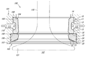
- FIG. 1 is a cross-sectional view of a valve seat ring according to the first embodiment.
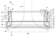
- FIG. 2 is a sectional view of the valve seat ring according to the second embodiment.
- FIG. 1 is a cross-sectional view of a valve seat ring 100 according to the first embodiment.
- the valve seat ring 100 according to this embodiment is a so-called cooling type valve seat ring, and is attached to a port formed in the cylinder head 101 of the reciprocating internal combustion engine.
- the valve seat ring 100 can be attached to an exhaust port of a 4-stroke engine, an intake port of a 4-stroke engine, an exhaust port of a 2-stroke engine, or the like.
- the axis of the valve seat ring 100 is simply referred to as “axis”, and the direction in which the axis extends (the vertical direction in FIG. 1 and FIG. 2) is referred to as “axis direction”.
- axis direction the direction in which the axis extends
- the combustion chamber 102 is formed below the valve seat ring, and the direction of the combustion chamber 102 (downward in FIG. 1 and FIG. 2) when viewed from the valve seat ring 100 is “axial center”.
- the direction opposite to the axially inward direction will be referred to as “axially outward”.
- a mounting hole 103 for mounting the valve seat ring 100 is formed in the cylinder head 101.
- the cylinder head 101 has a first end face 104, a first inner peripheral face 105, a second end face 106, and a second inner peripheral face 107, and a mounting hole 103 is defined by these faces.
- the respective surfaces 104 to 107 that define the mounting hole 103 will be described in order.
- the first end face 104 is located farthest from the combustion chamber 102 among the faces that define the attachment hole 103.
- the first end surface 104 is an annular surface perpendicular to the axial direction and faces the combustion chamber 102.
- the first inner peripheral surface 105 is a surface adjacent to the combustion chamber 102 side of the first end surface 104, and extends in the axial direction so as to surround the axial center.
- the inner diameter of the first inner peripheral surface 105 is constant regardless of the axial direction.
- An annular relief groove 108 is formed in the boundary portion (corner portion) between the first inner peripheral surface 105 and the first end surface 104 for processing reasons.
- the cylinder head 101 is formed with a cooling water flow path 110 through which cooling water for cooling the valve seat ring 100 flows.
- the cooling water flow path 110 has a supply cooling water flow path 111 through which cooling water flows in a direction toward the valve seat ring 100 and a discharge cooling water flow path 112 through which cooling water flows in a direction away from the valve seat ring 100 (in the drawing). See arrow). Both the supply cooling water flow path 111 and the discharge cooling water flow path 112 communicate with the mounting hole 103 via the first inner peripheral surface 105.
- the second end surface 106 is an annular surface that is adjacent to the combustion chamber 102 side of the first inner peripheral surface 105 and is perpendicular to the axial direction, and faces the combustion chamber 102.
- the second inner circumferential surface 107 is a surface adjacent to the combustion chamber 102 side of the second end surface 106 and extends in the axial direction so as to surround the axial center.
- the inner diameter of the second inner peripheral surface 107 is constant regardless of the axial direction, and is larger than the inner diameter of the first inner peripheral surface 105.
- An annular relief groove 109 is formed in the boundary portion (corner portion) between the second inner peripheral surface 107 and the second end surface 106 for processing reasons.
- the valve seat ring 100 includes a cooling ring portion 10 that is directly cooled by cooling water, and a seat ring portion 20 that is a member different from the cooling ring portion 10 and is in contact with the valve 120.
- the cooling ring unit 10 and the seat ring unit 20 will be described in order.
- the cooling ring portion 10 is formed in an annular shape (cylindrical shape), and an annular flow channel 12 is formed in the central portion of the outer peripheral portion 11 in the axial center direction.
- the channel groove 12 communicates (connects) with the supply cooling water channel 111 and the discharge cooling water channel 112. Therefore, the cooling water is supplied to the flow channel groove 12 through the supply cooling water flow channel 111, flows along the flow channel groove 12 while cooling the cooling ring portion 10 and its periphery, and is discharged from the discharge cooling water flow channel 112.
- the outer peripheral portion 11 of the cooling ring portion 10 has a first contact outer peripheral surface 13 in contact with the first inner peripheral surface 105 of the cylinder head 101.
- the first contact outer peripheral surface 13 is located on the axially outer side and the axially inner side of the flow path groove 12 and is formed in an annular shape. That is, the channel groove 12 is sandwiched between the first contact outer peripheral surfaces 13 that are located separately on both sides in the axial direction.
- the first contact outer peripheral surface 13 has a constant outer diameter regardless of the position in the axial direction. That is, the first contact outer peripheral surface 13 extends parallel to the axis.
- the cooling ring portion 10 is press-fitted into a portion corresponding to the first inner peripheral surface 105 of the mounting hole 103 formed in the cylinder head 101. Since the cooling ring unit 10 is a separate member from the seat ring unit 20, a difficult process of aligning the shaft center with the seat ring unit 20 is unnecessary, and the cooling ring unit 10 is processed to such an extent that press fitting can be performed. That's fine. Such processing is possible. Therefore, by sealing between the first contact outer peripheral surface 13 and the first inner peripheral surface 105 by press-fitting, both sides in the axial direction of the flow channel 12 are sealed, and the cooling water flowing through the flow channel 12 is outside. Will not leak. Thus, according to the present embodiment, it is possible to seal between the cooling ring portion 10 and the cylinder head 101 without using an O-ring that is easily affected by heat.
- the cooling ring portion 10 has a first outer end face 14 located in the axially outer portion and a first inner end face 15 located in the axially inner portion.
- the axial dimension from the first outer end face 14 to the first inner end face 15 is slightly smaller than the axial dimension from the first end face 104 to the second end face 106 of the cylinder head 101.
- the cooling ring portion 10 is press-fitted into the mounting hole 103 of the cylinder head 101 until the first outer end surface 14 contacts the first end surface 104. Therefore, the first inner end surface 15 of the present embodiment is located slightly outward in the axial direction from the second end surface 106.
- the seat ring portion 20 is formed in an annular shape (cylindrical shape), and is positioned inward in the axial direction from the cooling ring portion 10.
- the seat ring unit 20 is not coupled to the cooling ring unit 10.
- the seat ring portion 20 has a seat member 21 at an inner portion in the axial direction. Further, the seat member 21 has an annular seat surface 22 that is in close contact with the valve head 121 of the valve 120.
- the seat surface 22 is inclined so that the inner diameter increases as it goes inward in the axial direction.
- the seat surface 22 is worn by contact with the valve head 121.
- the seat ring portion 20 is a member different from the cooling ring portion 10. That is, the seat ring part 20 of the present embodiment is formed so as to be separable from the cooling ring part 10. Therefore, when the seat surface 22 is worn, only the seat ring portion 20 needs to be replaced. Thus, it is economical if only the seat ring portion 20 is replaced, and the sealing state between the cooling ring portion 10 and the cylinder head 101 is maintained even if the seat ring portion 20 is replaced. It is possible to reduce the risk of cooling water leaking from between.
- the outer peripheral portion 23 of the seat ring portion 20 has a second contact outer peripheral surface 24 that contacts the second inner peripheral surface 107 of the cylinder head 101.
- the outer diameter of the second contact outer peripheral surface 24 is constant regardless of the position in the axial direction.
- the seat ring part 20 since the seat ring part 20 must form the seat surface 22, it is necessary to ensure a certain dimension (thickness) in the radial direction.
- the cooling ring portion 10 of the present embodiment is formed to have an outer diameter smaller than that of the seat ring portion 20. That is, the seat ring portion 20 of the present embodiment is formed such that the outer diameter of the second contact outer peripheral surface 24 is larger than the outer diameter of the first contact outer peripheral surface 13.
- the seat ring portion 20 is press-fitted into a portion corresponding to the second inner peripheral surface 107 of the mounting hole 103 formed in the cylinder head 101. Since the seat ring part 20 is a member different from the cooling ring part 10, it is not necessary to perform a difficult process of matching the axis with the cooling ring part 10, and the seat ring part 20 is processed to such an extent that press fitting can be performed. That's fine. Such processing is possible. As described above, in the valve seat ring 100 according to the present embodiment, the cooling ring portion 10 and the seat ring portion 20 have different outer diameters, but the cooling ring portion 10 and the seat ring portion 20 are separate members. As a result, the entire valve seat ring 100 can be press-fitted into the mounting hole 103 of the cylinder head 101.
- the seat ring part 20 has a second outer end face 25 located at the axially outer part.
- the seat ring portion 20 is press-fitted into the mounting hole 103 of the cylinder head 101 until the second outer end surface 25 contacts the second end surface 106. Then, as described above, since the first inner end surface 15 of the cooling ring portion 10 is located outward of the second end surface 106 in the axial direction, the second outer end surface 25 of the seat ring portion 20 and the cooling ring A slight gap is formed between the first inner end face 15 of the part 10 and the seat ring part 20 is separated from the cooling ring part 10.
- the cavitation damage that causes a problem in the cooling type valve seat ring will be described.
- the valve seat ring 100 is cooled by the cooling water, but when the cooling water enters a narrow gap, bubbles are generated or disappeared in the cooling water due to vibration of the engine or the like. This phenomenon is called cavitation.
- the pressure wave generated when the bubbles generated by the cavitation break may damage the cylinder head 101 and the surrounding metal members. This is cavitation damage.
- FIG. 2 is a sectional view of the valve seat ring 200 according to the second embodiment.
- the valve seat ring 200 according to the present embodiment is different from the valve seat ring 100 according to the first embodiment in that the cooling ring portion 10 is formed by two members.
- the same configuration as the valve seat ring 100 according to the embodiment is provided. Below, it demonstrates centering around the structure of the cooling ring part 10 of this embodiment.
- the cooling ring portion 10 of the present embodiment includes an annular outer frame member 31 and an annular inner frame member 32 positioned on the radially inner side of the outer frame member 31.
- the cylinder head 101 of the present embodiment is formed with the same mounting hole 103 as the cylinder head 101 described in the first embodiment.
- the outer frame member 31 is formed in an L-shaped cross section, and has an outer end portion 33 extending in the radial direction in the cross-sectional view and an outer peripheral portion 34 extending in the axial direction in the cross-sectional view.
- the outer peripheral portion 34 has a first contact outer peripheral surface 13 that is in contact with the first inner peripheral surface 105 of the cylinder head 101.
- the outer diameter of the first contact outer peripheral surface 13 is constant regardless of the position in the axial direction.
- communication holes 35 penetrating the outer peripheral portion 34 in the radial direction are formed in portions corresponding to the supply cooling water flow path 111 and the discharge cooling water flow path 112 of the cylinder head 101.
- the outer circumferential portion 34 is not formed with the flow channel 12 (see FIG. 1) through which the cooling water passes.
- the inner frame member 32 is formed in an L-shaped cross section, and has an inner end portion 36 extending in the radial direction in the cross-sectional view and an inner peripheral portion 37 extending in the axial direction in the cross-sectional view.
- the outer end portion 33 of the outer frame member 31 and the inner peripheral portion 37 of the inner frame member 32 are connected by welding, and the outer peripheral portion 34 of the outer frame member 31 and the inner end portion 36 of the inner frame member 32 are connected by welding. ing.
- An annular inner flow path 38 is defined by the outer end portion 33 of the outer frame member 31, the outer peripheral portion 34 of the outer frame member 31, the inner end portion 36 of the inner frame member 32, and the inner peripheral portion 37 of the inner frame member 32. Has been.
- the inner flow path is formed in a portion surrounded by the outer end portion 33 of the outer frame member 31, the outer peripheral portion 34 of the outer frame member 31, the inner end portion 36 of the inner frame member 32, and the inner peripheral portion 37 of the inner frame member 32. 38 is formed.
- the internal flow path 38 communicates with the supply cooling water flow path 111 and the discharge cooling water flow path 112 through the communication hole 35 formed in the outer frame member 31. That is, the communication hole 35 connects the cooling water flow path 110 and the internal flow path 38. Therefore, the cooling water is supplied to the internal flow path 38 through the supply cooling water flow path 111, flows along the internal flow path 38 while cooling the cooling ring portion 10 and its periphery, and is discharged from the discharge cooling water flow path 112.
- the inner flow path 38 is formed by connecting the outer frame member 31 having an L-shaped cross section and the inner frame member 32 having an L-shaped cross section by welding.
- the ring unit 10 is not limited to this configuration.
- an annular member having a U-shaped cross section having an opening that opens in the radially inner direction, the radially outer direction, the axially outward direction, or the axially inward direction, and an annular member that blocks the opening. May be formed by welding to form the cooling ring portion 10 having the internal flow path 38.
- the cooling ring portion 10 may be integrally formed by, for example, precision casting instead of connecting two or more members by welding.
- the cooling ring portion 10 of the present embodiment is also press-fitted into a portion corresponding to the first inner peripheral surface 105 of the mounting hole 103 formed in the cylinder head 101 in the same manner as the cooling ring portion 10 of the first embodiment. Also in this embodiment, since the outer diameter of the first contact outer peripheral surface 13 is constant regardless of the position in the axial center direction, the first contact outer peripheral surface 13 can be processed with an accuracy that allows press-fitting. Thereby, the space between the first contact outer peripheral surface 13 and the first inner peripheral surface 105 is sealed by press fitting. In addition, since the cooling ring part 10 deform
- the boundary portion with the first contact outer peripheral surface 13 at the axially inner end of the flow path groove 12 is formed in a curved surface shape. ing. Then, when cooling water enters the gap formed between the boundary portion and the first inner peripheral surface 105, the cooling water may cause cavitation damage to the cylinder head 101. Since the valve seat ring 100 (cooling ring portion 10) is made of a material harder than the cylinder head 101, cavitation damage occurs only in the cylinder head 101.
- the flow groove 12 is not formed in the outer peripheral portion 11, so that cooling water is not provided between the cooling ring portion 10 and the cylinder head 101. No interstices are formed and cavitation damage does not occur. Even if a gap is formed so that cooling water enters the internal flow path 38, the cooling ring portion 10 is manufactured from a harder material than the cylinder head 101 or the like, and thus cavitation damage is unlikely to occur.
- Cooling ring part 11 Outer peripheral part 13 1st contact outer peripheral surface 20 Sheet ring part 22 Sheet surface 24 2nd contact outer peripheral surface 31 Outer frame member 32 Inner frame member 35 Communication hole 38 Internal flow path 100, 200 Valve seat ring 101 Cylinder head 103 mounting hole 110 cooling water flow path 111 supply cooling water flow path 112 discharge cooling water flow path 121 valve head
Landscapes
- Engineering & Computer Science (AREA)
- Mechanical Engineering (AREA)
- General Engineering & Computer Science (AREA)
- Gasket Seals (AREA)
Abstract
本発明の一態様に係る弁座リングは、シリンダヘッドに取り付けられる冷却型の弁座リングであって、シリンダヘッドの冷却水流路に接続する冷却リング部と、弁傘が接するシート面を有するシートリング部と、を備え、シートリング部が、冷却リング部とは別の部材であって、冷却リング部に対して分離可能に形成されている。
Description
本発明は、弁座リングに関する。
弁座リングは、内燃機関のシリンダヘッドに形成されたポートに設けられ、ポートを開閉するバルブの弁傘と接触する部材である。弁傘と接触する弁座リングのシート面は、温度が高いと摩耗が進行しやすくなることから、弁座リングが高温になる場合には、シリンダヘッド内に冷却水流路を形成し、この冷却水流路を通じて供給された冷却水によって温度を一定以下に保つ冷却型の弁座リングが採用される(特許文献1参照)。冷却型の弁座リングを採用する場合、弁座リングとシリンダヘッドの間から冷却水が漏れないように、両部材の間をシールする必要がある。
ところで、冷却型の弁座リングを用いたとしてもシート面の摩耗は進行することから、弁座リングは定期的に交換する必要がある。ただし、冷却型の弁座リングを用いる場合には、取り付け及び取り外しする際にシール面が傷つき、交換後にシール不良が発生するという特有の問題が発生するリスクがある。
このような事情に鑑み、本発明は、交換に起因するシール不良が発生しにくい冷却型の弁座リングを提供することを目的としている。
本発明の一態様に係る弁座リングは、シリンダヘッドに取り付けられる冷却型の弁座リングであって、前記シリンダヘッドに形成された冷却水流路に接続する冷却リング部と、弁傘が接するシート面を有するシートリング部と、を備え、前記シートリング部が、前記冷却リング部とは別の部材であって、前記冷却リング部に対して分離可能に形成されている。
この構成によれば、シート面が摩耗した際には、シートリング部を交換すれば足り、冷却リング部を交換する必要がない。よって、シートリング部の交換によってシール面が傷つくことはないため、交換に起因するシール不良は発生しない。
また、上記の弁座リングにおいて、前記冷却リング部の前記シリンダヘッドに接する第1接触外周面の外径が一定であり、前記シートリング部の前記シリンダヘッドに接する第2接触外周面の外径が一定であって、かつ、前記第1接触外周面の外径よりも大きく構成してもよい。
ここで、シリンダヘッドに形成されたポートの断面積(流路面積)を大きくすれば内燃機関の性能を向上させることができる。ところが、シート面を有する弁座リングは、シート面が形成できるように径方向の幅(厚み)をある程度大きくする必要があるため、シリンダヘッド内の他の部分と干渉しやすく、大きな流路面積を確保することができない場合がある。このような場合には、弁座リングのうちシート面が形成される部分の厚みを大きくし、それ以外の部分は厚みを小さくすれば(つまり弁座リングのうちシート面が形成される部分以外の部分の外径を小さくすれば)、弁座リングがシリンダヘッド内の他の部分と干渉するのを回避しつつ、大きな流路面積を確保することができる。
ただし、外径が一定でない弁座リングはシリンダヘッドの取付孔へ圧入することはできない。なぜなら、外径が一定でない弁座リングを圧入するのであれば、異なる外径を有する部分の軸心を互いに高い精度で一致させる必要があるところ、そのような加工は困難だからである。そのため、外径が一定ではない弁座リングは、圧入によって弁座リングとシリンダヘッドの間をシールすることはできず、弁座リングとシリンダヘッドとの間にはOリングを設ける必要がある(特許文献1の図2参照)。しかしながら、Oリングは熱の影響を受けやすいという問題がある。
これに対し、上記の構成によれば、大きな流路面積を確保できるようにシートリング部と冷却リング部は外径が異なるように形成されているが、シートリング部は冷却リング部とは別の部材であるため、冷却リング部とシートリング部の軸心を互いに一致させる加工は不要である。つまり、冷却リング部及びシートリング部はシリンダヘッドの取付孔に圧入できるような加工が可能であり、圧入による弁座リングとシリンダヘッドの間のシールが可能である。そのため、弁座リングとシリンダヘッドの間にOリングを設ける必要がない。よって、上記の弁座リングによれば、大きな流路面積を確保しつつ、シリンダヘッドとの間にシール用のOリングを省略することができる。
また、上記の弁座リングにおいて、前記冷却リング部には、環状の内部流路と、前記冷却水路と前記内部流路をつなぐ連通孔と、が形成されていてもよい。
この構成によれば、キャビテーション損傷が発生しにくい。また、仮に、内部流路内にキャビテーションが発生したとしても、弁座リングは比較的硬い材料で形成されているため損傷しにくい。
また、上記の弁座リングにおいて、前記冷却リング部は、前記第1接触外周面を有する外枠部材と、前記外枠部材の径方向内側に位置する内枠部材と、を有し、前記外枠部材と前記内枠部材の間には前記内部流路が形成されており、前記外枠部材には前記連通孔が形成されていてもよい。
この構成によれば、冷却リング部に上述した内部流路及び連通孔を容易に形成することができる。
また、上記の弁座リングにおいて、前記シートリング部は、前記冷却リング部に対して離間していてもよい。
この構成によれば、冷却リング部とシリンダヘッドの間から冷却水が漏れたとしても、その冷却水はシートリング部と冷却リング部の間を通って空気流路側に排出される。そのため、シートリング部とシリンダヘッドの間に形成された隙間に冷却水が侵入するのを防ぐことができる結果、当該隙間においてキャビテーション損傷が発生するのを防ぐことができる。なお、シートリング部が冷却リング部に対して離間していたとしても、シートリング部の周辺に冷却水が流れていれば、シートリング部周辺の部材温度が低下し、シートリング部の温度も低下する。
以上のとおり、上記の弁座リングによれば、交換に起因するシール不良を防ぐことができる。
(第1実施形態)
まず、第1実施形態について説明する。図1は、第1実施形態に係る弁座リング100の断面図である。本実施形態に係る弁座リング100は、いわゆる冷却型の弁座リングであって、往復動内燃機関のシリンダヘッド101に形成されたポートに取り付けられる。具体的には、弁座リング100は、4ストロークエンジンの排気ポート、4ストロークエンジンの吸気ポート、2ストロークエンジンの排気ポート等に取り付けることができる。
まず、第1実施形態について説明する。図1は、第1実施形態に係る弁座リング100の断面図である。本実施形態に係る弁座リング100は、いわゆる冷却型の弁座リングであって、往復動内燃機関のシリンダヘッド101に形成されたポートに取り付けられる。具体的には、弁座リング100は、4ストロークエンジンの排気ポート、4ストロークエンジンの吸気ポート、2ストロークエンジンの排気ポート等に取り付けることができる。
なお、以下では、弁座リング100の軸心を単に「軸心」と称し、この軸心が延在する方向(図1及び図2における紙面上下方向)を「軸心方向」と称して説明する。また、図1及び図2において、弁座リングの紙面下方に燃焼室102が形成されており、弁座リング100からみて燃焼室102の方向(図1及び図2の紙面下方)を「軸心方向内方」と称し、この軸心方向内方と逆の方向を「軸心方向外方」と称して説明する。
<シリンダヘッド>
弁座リング100の構成を説明する前に、弁座リング100が取り付けられるシリンダヘッド101について説明する。シリンダヘッド101には、弁座リング100を取り付けるための取付孔103が形成されている。シリンダヘッド101は、第1端面104、第1内周面105、第2端面106、第2内周面107を有しており、これら面によって取付孔103が画されている。以下、取付孔103を画する各面104~107について順に説明する。
弁座リング100の構成を説明する前に、弁座リング100が取り付けられるシリンダヘッド101について説明する。シリンダヘッド101には、弁座リング100を取り付けるための取付孔103が形成されている。シリンダヘッド101は、第1端面104、第1内周面105、第2端面106、第2内周面107を有しており、これら面によって取付孔103が画されている。以下、取付孔103を画する各面104~107について順に説明する。
第1端面104は、取付孔103を画する面のうち燃焼室102から最も遠くに位置している。第1端面104は、軸心方向に対して垂直な環状の面であって、燃焼室102に面している。第1内周面105は、第1端面104の燃焼室102側に隣接する面であって、軸心を囲むようにして軸心方向に延びている。第1内周面105の内径は、軸心方向にかかわらず一定である。また、第1内周面105と第1端面104の境界部分(角部)には、加工上の理由から環状の逃げ溝108が形成されている。
ここで、シリンダヘッド101には、弁座リング100を冷却するための冷却水が流れる冷却水流路110が形成されている。冷却水流路110は、弁座リング100に向かう方向に冷却水が流れる供給冷却水流路111と、弁座リング100から離れる方向に冷却水が流れる排出冷却水流路112を有している(図中の矢印参照)。供給冷却水流路111及び排出冷却水流路112は、いずれも第1内周面105を介して取付孔103に連通している。
第2端面106は、第1内周面105の燃焼室102側に隣接し、軸心方向に対して垂直な環状の面であって、燃焼室102に面している。第2内周面107は、第2端面106の燃焼室102側に隣接する面であって、軸心を囲むようにして軸心方向に延びている。第2内周面107の内径は、軸心方向にかかわらず一定であるとともに、第1内周面105の内径よりも大きい。また、第2内周面107と第2端面106の境界部分(角部)には、加工上の理由から環状の逃げ溝109が形成されている。
<弁座リングの冷却リング部>
続いて、本実施形態に係る弁座リング100について説明する。弁座リング100は、冷却水によって直接冷却される冷却リング部10と、冷却リング部10とは別の部材であってバルブ120に接するシートリング部20とを備えている。以下、冷却リング部10及びシートリング部20について順に説明する。
続いて、本実施形態に係る弁座リング100について説明する。弁座リング100は、冷却水によって直接冷却される冷却リング部10と、冷却リング部10とは別の部材であってバルブ120に接するシートリング部20とを備えている。以下、冷却リング部10及びシートリング部20について順に説明する。
冷却リング部10は、環状(筒状)に形成されており、外周部11の軸心方向中央部分には環状の流路溝12が形成されている。流路溝12は、供給冷却水流路111及び排出冷却水流路112と連通(接続)している。そのため、冷却水は、供給冷却水流路111を通って流路溝12に供給され、冷却リング部10及びその周辺を冷却しながら流路溝12に沿って流れ、排出冷却水流路112から排出される。
また、冷却リング部10の外周部11は、シリンダヘッド101の第1内周面105に接する第1接触外周面13を有している。第1接触外周面13は、流路溝12よりも軸心方向外方と軸心方向内方に位置しており環状に形成されている。つまり、流路溝12は、軸心方向の両側に分かれて位置する第1接触外周面13に挟まれている。そして、第1接触外周面13は、軸心方向位置にかかわらず外径が一定である。つまり、第1接触外周面13は、軸心に対して平行に延びている。
また、冷却リング部10は、シリンダヘッド101に形成された取付孔103の第1内周面105に対応する部分に圧入されている。冷却リング部10は、シートリング部20とは別の部材であるため、シートリング部20と軸心を一致させるような難しい加工は不要であり、圧入を行える程度に冷却リング部10を加工すればよい。このような加工は可能である。よって、第1接触外周面13と第1内周面105との間を圧入によってシールされることで、流路溝12の軸心方向両側がシールされ、流路溝12を流れる冷却水が外部に漏れることはない。このように、本実施形態によれば、熱の影響を受けやすいOリングを用いずに、冷却リング部10とシリンダヘッド101の間をシールすることができる。
また、冷却リング部10は、軸心方向外方部分に位置する第1外端面14と、軸心方向内方部分に位置する第1内端面15とを有している。第1外端面14から第1内端面15までの軸心方向寸法は、シリンダヘッド101の第1端面104から第2端面106までの軸心方向寸法よりもわずかに小さい。そして、冷却リング部10は、第1外端面14が第1端面104に接するまで、シリンダヘッド101の取付孔103に圧入されている。そのため、本実施形態の第1内端面15は、第2端面106よりもわずかに軸心方向外方に位置している。
<弁座リングのシートリング部>
シートリング部20は、環状(筒状)に形成されており、冷却リング部10よりも軸心方向内方に位置している。なお、シートリング部20は、冷却リング部10に結合されていない。シートリング部20は、軸心方向内方部分にシート部材21を有している。さらに、シート部材21は、バルブ120の弁傘121と密着する環状のシート面22を有している。シート面22は、軸心方向内方に向かうにしたがって内径が大きくなるように傾斜している。
シートリング部20は、環状(筒状)に形成されており、冷却リング部10よりも軸心方向内方に位置している。なお、シートリング部20は、冷却リング部10に結合されていない。シートリング部20は、軸心方向内方部分にシート部材21を有している。さらに、シート部材21は、バルブ120の弁傘121と密着する環状のシート面22を有している。シート面22は、軸心方向内方に向かうにしたがって内径が大きくなるように傾斜している。
上記のシート面22は弁傘121との接触によって摩耗する。ここで、上記のとおり、シートリング部20は冷却リング部10とは別の部材である。つまり、本実施形態のシートリング部20は、冷却リング部10に対して分離可能に形成されている。そのため、シート面22が摩耗した際には、シートリング部20のみを交換すればよい。このようにシートリング部20のみを交換すれば経済的であるとともに、交換を行っても冷却リング部10とシリンダヘッド101のシール状態が維持されるため、冷却リング部10とシリンダヘッド101との間から冷却水が漏れるリスクを低減することができる。
また、シートリング部20の外周部23は、シリンダヘッド101の第2内周面107に接する第2接触外周面24を有している。第2接触外周面24は、軸心方向位置にかかわらず外径が一定である。ここで、シートリング部20はシート面22を形成しなければならないため、径方向の寸法(厚み)を一定以上確保する必要がある。ただし、冷却リング部10の厚みをシートリング部20の厚みと同じにすると、シリンダヘッド101内の他の部分と干渉するおそれがある。そこで、本実施形態の冷却リング部10は、シートリング部20よりも外径が小さく形成されている。すなわち、本実施形態のシートリング部20は、第2接触外周面24の外径が第1接触外周面13の外径よりも大きくなるように形成されている。
また、シートリング部20は、シリンダヘッド101に形成された取付孔103の第2内周面107に対応する部分に圧入されている。シートリング部20は、冷却リング部10とは別の部材であるため、冷却リング部10と軸心を一致させるような難しい加工は不要であり、圧入を行える程度にシートリング部20を加工すればよい。このような加工は可能である。このように、本実施形態の弁座リング100は、冷却リング部10とシートリング部20の外径が異なるが、冷却リング部10とシートリング部20が別の部材であるため、それぞれを別々に加工できる結果、弁座リング100全体をシリンダヘッド101の取付孔103に圧入することができる。
また、シートリング部20は、軸心方向外方部分に位置する第2外端面25を有している。シートリング部20は、第2外端面25が第2端面106に接するまで、シリンダヘッド101の取付孔103に圧入されている。そうすると、前述したとおり、冷却リング部10の第1内端面15は、第2端面106よりも軸心方向外方に位置していることから、シートリング部20の第2外端面25と冷却リング部10の第1内端面15との間にはわずかな隙間が形成されており、シートリング部20は冷却リング部10に対して離間している。
ここで、冷却型の弁座リングにおいて問題となるキャビテーション損傷について説明する。前述のとおり、弁座リング100は冷却水によって冷却されるが、冷却水が狭い隙間に入り込むと、エンジンの振動等によって冷却水の内部に気泡が発生したり消滅したりする。この現象をキャビテーションと呼んでいる。このキャビテーションによって発生した気泡が分裂する際に発生する圧力波によってシリンダヘッド101及びその周辺の金属部材が損傷する場合がある。これがキャビテーション損傷である。
ここで、仮に冷却水が第1接触外周部13と第1内周面105の間を通ってシートリング部20側に漏れた場合には、逃げ溝109の部分においてキャビテーション損傷が発生するおそれがある。しかしながら、本実施形態では、シートリング部20の第2外端面25と冷却リング部10の第1内端面15との間に隙間が形成されているため、漏れた冷却水が逃げ溝109に侵入することはなく、キャビテーション損傷が発生するのを防ぐことができる。
(第2実施形態)
次に、第2実施形態について説明する。図2は、第2実施形態に係る弁座リング200の断面図である。以下では、図2で示す要素のうち、図1で示す要素と同一又は相当するものについては同じ符号を付し、第1実施形態と重複する説明は省略する。なお、本実施形態に係る弁座リング200は、冷却リング部10が2つの部材によって形成されている点で第1実施形態に係る弁座リング100と異なるが、それ以外は基本的に第1実施形態に係る弁座リング100と同じ構成を備えている。以下では本実施形態の冷却リング部10の構成を中心に説明する。
次に、第2実施形態について説明する。図2は、第2実施形態に係る弁座リング200の断面図である。以下では、図2で示す要素のうち、図1で示す要素と同一又は相当するものについては同じ符号を付し、第1実施形態と重複する説明は省略する。なお、本実施形態に係る弁座リング200は、冷却リング部10が2つの部材によって形成されている点で第1実施形態に係る弁座リング100と異なるが、それ以外は基本的に第1実施形態に係る弁座リング100と同じ構成を備えている。以下では本実施形態の冷却リング部10の構成を中心に説明する。
図2に示すように、本実施形態の冷却リング部10は、環状の外枠部材31と、外枠部材31の径方向内側に位置する環状の内枠部材32と、を有している。なお、本実施形態のシリンダヘッド101には、第1実施形態で説明したシリンダヘッド101と同じ取付孔103が形成されている。
外枠部材31は、断面L字状に形成されており、断面視において径方向に延びる外端部33と、断面視において軸心方向に延びる外周部34とを有している。また、外周部34はシリンダヘッド101の第1内周面105に接する第1接触外周面13を有している。第1接触外周面13は、軸心方向位置にかかわらず外径が一定である。さらに、外周部34のうち、シリンダヘッド101の供給冷却水流路111及び排出冷却水流路112に対応する部分には、それぞれ外周部34を径方向に貫通する連通孔35が形成されている。なお、本実施形態では外周部34には、冷却水が通る流路溝12(図1参照)は形成されていない。
内枠部材32は、断面L字状に形成されており、断面視において径方向に延びる内端部36と、断面視において軸心方向に延びる内周部37とを有している。外枠部材31の外端部33と内枠部材32の内周部37が溶接によって接続されており、外枠部材31の外周部34と内枠部材32の内端部36が溶接によって接続されている。そして、外枠部材31の外端部33、外枠部材31の外周部34、内枠部材32の内端部36、及び内枠部材32の内周部37によって環状の内部流路38が画されている。つまり、外枠部材31の外端部33、外枠部材31の外周部34、内枠部材32の内端部36、及び内枠部材32の内周部37によって囲まれた部分に内部流路38が形成されている。
この内部流路38は、外枠部材31に形成された連通孔35を介して供給冷却水流路111及び排出冷却水流路112と連通している。つまり、連通孔35は、冷却水流路110と内部流路38をつないでいる。そのため、冷却水は、供給冷却水流路111を通って内部流路38に供給され、冷却リング部10及びその周辺を冷却しながら内部流路38に沿って流れ、排出冷却水流路112から排出される。
なお、本実施形態の冷却リング部10では、断面L字状の外枠部材31と断面L字状の内枠部材32を溶接によって接続することにより内部流路38を形成しているが、冷却リング部10はこの構成に限られない。例えば、径方向内側方向、径方向外側方向、軸心方向外方、又は軸心方向内方に開口する開口部を有する断面U字状の環状の部材と、この開口部をふさぐ環状の部材とを溶接によって接続することにより、内部流路38を有する冷却リング部10を形成してもよい。さらに、冷却リング部10は、2つ又は2つ以上の部材を溶接によって接続するのではなく、例えば精密鋳造等で一体に形成してもよい。
本実施形態の冷却リング部10も、第1実施形態の冷却リング部10と同様にシリンダヘッド101に形成された取付孔103の第1内周面105に対応する部分に圧入されている。本実施形態の場合も第1接触外周面13は軸心方向位置にかかわらず外径が一定であることから、圧入を行える程度の精度で加工を行うことができる。これにより、第1接触外周面13と第1内周面105との間が圧入によってシールされる。なお、冷却リング部10は、外枠部材31と内枠部材32を溶接する際の熱によって変形するため、第1接触外周面13の加工は、溶接作業後に行うのが望ましい。
ここで、図1に示すように、第1実施形態の冷却リング部10は、流路溝12の軸心方向内方端部における第1接触外周面13との境界部分は曲面状に形成されている。そうすると、当該境界部分と第1内周面105の間に形成された隙間に冷却水が侵入すると、その冷却水によってシリンダヘッド101にキャビテーション損傷が発生するおそれがある。なお、弁座リング100(冷却リング部10)は、シリンダヘッド101よりも硬い材料で製造されるため、キャビテーション損傷はシリンダヘッド101にのみ発生する。
これに対し、図2に示すように、本実施形態の冷却リング部10は、外周部11に流路溝12が形成されていないため、冷却リング部10とシリンダヘッド101の間に冷却水が入り込むような隙間が形成されず、キャビテーション損傷は発生しない。また、仮に内部流路38内に冷却水が入り込むような隙間が形成されたとしても、冷却リング部10はシリンダヘッド101等に比べて硬い材料で製造されるため、キャビテーション損傷が発生しにくい。
10 冷却リング部
11 外周部
13 第1接触外周面
20 シートリング部
22 シート面
24 第2接触外周面
31 外枠部材
32 内枠部材
35 連通孔
38 内部流路
100、200 弁座リング
101 シリンダヘッド
103 取付孔
110 冷却水流路
111 供給冷却水流路
112 排出冷却水流路
121 弁傘
11 外周部
13 第1接触外周面
20 シートリング部
22 シート面
24 第2接触外周面
31 外枠部材
32 内枠部材
35 連通孔
38 内部流路
100、200 弁座リング
101 シリンダヘッド
103 取付孔
110 冷却水流路
111 供給冷却水流路
112 排出冷却水流路
121 弁傘
Claims (5)
- シリンダヘッドに取り付けられる冷却型の弁座リングであって、
前記シリンダヘッドの冷却水流路に接続する冷却リング部と、
弁傘が接するシート面を有するシートリング部と、を備え、
前記シートリング部が、前記冷却リング部とは別の部材であって、前記冷却リング部に対して分離可能に形成されている、弁座リング。 - 前記冷却リング部の前記シリンダヘッドに接する第1接触外周面の外径が一定であり、
前記シートリング部の前記シリンダヘッドに接する第2接触外周面の外径が一定であって、かつ、前記第1接触外周面の外径よりも大きい、請求項1に記載の弁座リング。 - 前記冷却リング部には、環状の内部流路と、前記冷却水路と前記内部流路をつなぐ連通孔と、が形成されている、請求項2に記載の弁座リング。
- 前記冷却リング部は、
前記第1接触外周面を有する外枠部材と、
前記外枠部材の径方向内側に位置する内枠部材と、を有し、
前記外枠部材と前記内枠部材の間には前記内部流路が形成されており、
前記外枠部材には前記連通孔が形成されている、請求項3に記載の弁座リング。 - 前記シートリング部が、前記冷却リング部に対して離間している、請求項1乃至4のうちいずれか一の項に記載の弁座リング。
Applications Claiming Priority (2)
| Application Number | Priority Date | Filing Date | Title |
|---|---|---|---|
| JP2015231399A JP2017096219A (ja) | 2015-11-27 | 2015-11-27 | 弁座リング |
| JP2015-231399 | 2015-11-27 |
Publications (1)
| Publication Number | Publication Date |
|---|---|
| WO2017090330A1 true WO2017090330A1 (ja) | 2017-06-01 |
Family
ID=58763995
Family Applications (1)
| Application Number | Title | Priority Date | Filing Date |
|---|---|---|---|
| PCT/JP2016/080257 Ceased WO2017090330A1 (ja) | 2015-11-27 | 2016-10-12 | 弁座リング |
Country Status (2)
| Country | Link |
|---|---|
| JP (1) | JP2017096219A (ja) |
| WO (1) | WO2017090330A1 (ja) |
Cited By (5)
| Publication number | Priority date | Publication date | Assignee | Title |
|---|---|---|---|---|
| JP2020051335A (ja) * | 2018-09-27 | 2020-04-02 | 川崎重工業株式会社 | シリンダカバーおよびその耐食性向上方法 |
| WO2020102139A1 (en) * | 2018-11-13 | 2020-05-22 | Caterpillar Inc. | Valve seat insert for engine having double-crowned seating surface profiled for limiting valve recession |
| WO2020101938A1 (en) * | 2018-11-13 | 2020-05-22 | Caterpillar Inc. | Valve seat insert for internal combustion engine profiled to resist valve recession |
| JPWO2021161444A1 (ja) * | 2020-02-13 | 2021-08-19 | ||
| CN115306577A (zh) * | 2022-09-03 | 2022-11-08 | 湖南天雁机械有限责任公司 | 一种发动机缸盖结构 |
Citations (5)
| Publication number | Priority date | Publication date | Assignee | Title |
|---|---|---|---|---|
| JPS5079697U (ja) * | 1973-11-26 | 1975-07-09 | ||
| JPS5178650U (ja) * | 1974-12-17 | 1976-06-21 | ||
| JPS52143346A (en) * | 1976-05-24 | 1977-11-29 | Sulzer Ag | Exhaust valve of piston type internal combustion engine |
| JPS54135011U (ja) * | 1978-03-11 | 1979-09-19 | ||
| JP2005344712A (ja) * | 2004-06-02 | 2005-12-15 | Man B & W Diesel Gmbh | 冷却型弁座リング |
-
2015
- 2015-11-27 JP JP2015231399A patent/JP2017096219A/ja active Pending
-
2016
- 2016-10-12 WO PCT/JP2016/080257 patent/WO2017090330A1/ja not_active Ceased
Patent Citations (5)
| Publication number | Priority date | Publication date | Assignee | Title |
|---|---|---|---|---|
| JPS5079697U (ja) * | 1973-11-26 | 1975-07-09 | ||
| JPS5178650U (ja) * | 1974-12-17 | 1976-06-21 | ||
| JPS52143346A (en) * | 1976-05-24 | 1977-11-29 | Sulzer Ag | Exhaust valve of piston type internal combustion engine |
| JPS54135011U (ja) * | 1978-03-11 | 1979-09-19 | ||
| JP2005344712A (ja) * | 2004-06-02 | 2005-12-15 | Man B & W Diesel Gmbh | 冷却型弁座リング |
Cited By (14)
| Publication number | Priority date | Publication date | Assignee | Title |
|---|---|---|---|---|
| JP2020051335A (ja) * | 2018-09-27 | 2020-04-02 | 川崎重工業株式会社 | シリンダカバーおよびその耐食性向上方法 |
| GB2593995B (en) * | 2018-11-13 | 2023-01-25 | Caterpillar Inc | Valve seat insert for engine having double-crowned seating surface profiled for limiting valve recession |
| WO2020102139A1 (en) * | 2018-11-13 | 2020-05-22 | Caterpillar Inc. | Valve seat insert for engine having double-crowned seating surface profiled for limiting valve recession |
| WO2020101938A1 (en) * | 2018-11-13 | 2020-05-22 | Caterpillar Inc. | Valve seat insert for internal combustion engine profiled to resist valve recession |
| US10731523B2 (en) | 2018-11-13 | 2020-08-04 | Caterpillar Inc. | Valve seat insert for internal combustion engine profiled to resist valve recession |
| US10934899B2 (en) | 2018-11-13 | 2021-03-02 | Caterpillar Inc. | Valve seat insert for engine having double-crowned seating surface profiled for limiting valve recession |
| CN112955633A (zh) * | 2018-11-13 | 2021-06-11 | 卡特彼勒公司 | 具有被成形用于限制阀凹陷的双冠状座表面的用于发动机的阀座插入件 |
| CN112955633B (zh) * | 2018-11-13 | 2023-10-27 | 卡特彼勒公司 | 具有被成形用于限制阀凹陷的双冠状座表面的用于发动机的阀座插入件 |
| GB2593995A (en) * | 2018-11-13 | 2021-10-13 | Caterpillar Inc | Valve seat insert for engine having double-crowned seating surface profiled for limiting valve recession |
| JPWO2021161444A1 (ja) * | 2020-02-13 | 2021-08-19 | ||
| JP7336543B2 (ja) | 2020-02-13 | 2023-08-31 | 川崎重工業株式会社 | シリンダカバーおよびその耐食性向上方法 |
| WO2021161444A1 (ja) * | 2020-02-13 | 2021-08-19 | 川崎重工業株式会社 | シリンダカバーおよびその耐食性向上方法 |
| EP4105473A4 (en) * | 2020-02-13 | 2023-11-01 | Kawasaki Jukogyo Kabushiki Kaisha | Cylinder cover and method for improving corrosion resistance thereof |
| CN115306577A (zh) * | 2022-09-03 | 2022-11-08 | 湖南天雁机械有限责任公司 | 一种发动机缸盖结构 |
Also Published As
| Publication number | Publication date |
|---|---|
| JP2017096219A (ja) | 2017-06-01 |
Similar Documents
| Publication | Publication Date | Title |
|---|---|---|
| WO2017090330A1 (ja) | 弁座リング | |
| US20150184531A1 (en) | Gasket device for the bearing of a turbomachine, comprising two elastic seals | |
| US10047640B2 (en) | Roller tappet and method for manufacturing a housing element of a roller tappet | |
| US20120025473A1 (en) | Shaft sealing apparatus | |
| JP6884630B2 (ja) | ターボチャージャ用ハウジング及びその製造方法 | |
| US10408162B2 (en) | Cylinder head for an internal combustion engine | |
| CN106715846A (zh) | 用于内燃机的阀座嵌件 | |
| JP5259463B2 (ja) | 高温用デッドエンドシール | |
| JPWO2016059883A1 (ja) | シール装置 | |
| US20100111692A1 (en) | Exhaust gas turbocharger for a motor vehicle | |
| US20140265142A1 (en) | Carbon seal assembly | |
| CN104379928B (zh) | 用于燃料喷射系统的高压泵 | |
| JP6261857B2 (ja) | シリンダカバー、シリンダヘッドガスケット及び内燃機関 | |
| JP7224286B2 (ja) | バルブステムシール | |
| US10508616B2 (en) | Oil flow control for an engine by deflection | |
| CN116378832A (zh) | 一种航空发动机机匣与管路间密封结构 | |
| WO2024145885A1 (zh) | 一种液力端和压裂泵 | |
| JP6445388B2 (ja) | 軸封装置 | |
| US10036474B2 (en) | Vented lift off seal assemblies | |
| CN106233045B (zh) | 具有捕获的流体传输管的压力控制的动态密封件 | |
| JP5364426B2 (ja) | ターボ機械 | |
| JP6270380B2 (ja) | 内燃機関 | |
| JP2008025654A (ja) | クランクシャフト用オイルシールの取り付け構造 | |
| US20110156360A1 (en) | Seal device | |
| KR200406092Y1 (ko) | 실린더 냉각을 향상시킨 라이너 구조 |
Legal Events
| Date | Code | Title | Description |
|---|---|---|---|
| 121 | Ep: the epo has been informed by wipo that ep was designated in this application |
Ref document number: 16868279 Country of ref document: EP Kind code of ref document: A1 |
|
| NENP | Non-entry into the national phase |
Ref country code: DE |
|
| 122 | Ep: pct application non-entry in european phase |
Ref document number: 16868279 Country of ref document: EP Kind code of ref document: A1 |