WO2017090291A1 - ポンプ装置 - Google Patents
ポンプ装置 Download PDFInfo
- Publication number
- WO2017090291A1 WO2017090291A1 PCT/JP2016/075279 JP2016075279W WO2017090291A1 WO 2017090291 A1 WO2017090291 A1 WO 2017090291A1 JP 2016075279 W JP2016075279 W JP 2016075279W WO 2017090291 A1 WO2017090291 A1 WO 2017090291A1
- Authority
- WO
- WIPO (PCT)
- Prior art keywords
- unit
- fan
- control unit
- pump device
- pump
- Prior art date
- Legal status (The legal status is an assumption and is not a legal conclusion. Google has not performed a legal analysis and makes no representation as to the accuracy of the status listed.)
- Ceased
Links
Images







Classifications
-
- F—MECHANICAL ENGINEERING; LIGHTING; HEATING; WEAPONS; BLASTING
- F04—POSITIVE - DISPLACEMENT MACHINES FOR LIQUIDS; PUMPS FOR LIQUIDS OR ELASTIC FLUIDS
- F04B—POSITIVE-DISPLACEMENT MACHINES FOR LIQUIDS; PUMPS
- F04B53/00—Component parts, details or accessories not provided for in, or of interest apart from, groups F04B1/00 - F04B23/00 or F04B39/00 - F04B47/00
-
- F—MECHANICAL ENGINEERING; LIGHTING; HEATING; WEAPONS; BLASTING
- F04—POSITIVE - DISPLACEMENT MACHINES FOR LIQUIDS; PUMPS FOR LIQUIDS OR ELASTIC FLUIDS
- F04B—POSITIVE-DISPLACEMENT MACHINES FOR LIQUIDS; PUMPS
- F04B53/00—Component parts, details or accessories not provided for in, or of interest apart from, groups F04B1/00 - F04B23/00 or F04B39/00 - F04B47/00
- F04B53/08—Cooling; Heating; Preventing freezing
-
- F—MECHANICAL ENGINEERING; LIGHTING; HEATING; WEAPONS; BLASTING
- F04—POSITIVE - DISPLACEMENT MACHINES FOR LIQUIDS; PUMPS FOR LIQUIDS OR ELASTIC FLUIDS
- F04D—NON-POSITIVE-DISPLACEMENT PUMPS
- F04D13/00—Pumping installations or systems
- F04D13/02—Units comprising pumps and their driving means
- F04D13/06—Units comprising pumps and their driving means the pump being electrically driven
- F04D13/08—Units comprising pumps and their driving means the pump being electrically driven for submerged use
-
- F—MECHANICAL ENGINEERING; LIGHTING; HEATING; WEAPONS; BLASTING
- F04—POSITIVE - DISPLACEMENT MACHINES FOR LIQUIDS; PUMPS FOR LIQUIDS OR ELASTIC FLUIDS
- F04D—NON-POSITIVE-DISPLACEMENT PUMPS
- F04D29/00—Details, component parts, or accessories
-
- F—MECHANICAL ENGINEERING; LIGHTING; HEATING; WEAPONS; BLASTING
- F04—POSITIVE - DISPLACEMENT MACHINES FOR LIQUIDS; PUMPS FOR LIQUIDS OR ELASTIC FLUIDS
- F04D—NON-POSITIVE-DISPLACEMENT PUMPS
- F04D29/00—Details, component parts, or accessories
- F04D29/58—Cooling; Heating; Diminishing heat transfer
Definitions
- the present invention relates to a pump device, and particularly to a pump device provided with a submersible pump unit.
- a pump device for transferring water in a well to the ground includes a submersible pump unit disposed in a well and a land unit connected to the submersible pump unit through a suction pipe.
- the land unit includes components such as an inverter that can change the electric motor of the submersible pump unit, and a control unit that controls the operation of the inverter.
- the inverter When the pump device is operated, the inverter generates heat with the operation of the submersible pump unit, and the inverter temperature becomes very high. Then, in order to cool an inverter, the pump apparatus provided with the radiation fin provided in the inverter and the fan which sends an airflow to a radiation fin is known (for example, refer patent document 1).
- the pump device of Patent Document 1 includes a cylindrical portion that surrounds the heat dissipating fins and the fan. When the fan rotates, air flows through the cylinder through the fan, and cools the inverter through the radiation fins.
- a cylindrical portion having thermal conductivity is required, so that the number of parts necessary for cooling the inverter is increased, and the structure of the pump device is complicated.
- the shape of the cylindrical portion for surrounding the radiating fin and the fan is complicated. Furthermore, since the air flowing in the cylinder portion cools the inverter only through the radiation fins, the cooling efficiency is low.
- the cooling performance is improved by bringing the cylinder portion into surface contact with the block portion.
- the block portion vibrates due to water flowing during operation of the pump, the cylinder portion that contacts the block portion. Vibrate, and as a result, the inverter also vibrates.
- an object of the present invention is to provide a pump device that can cool an inverter efficiently with a simple structure.
- One aspect of the present invention includes a submersible pump unit including a pump and an electric motor, and a land unit connected to the submersible pump unit via a suction pipe, and the land unit includes a control unit having a radiation fin; A water distribution pipe connected to the suction pipe; and a fan facing the heat dissipating fin; and the control unit includes an inverter capable of shifting the electric motor, a control unit for controlling the operation of the inverter, and the inverter. And a protective cover that covers the control unit, the protective cover has a plurality of ventilation holes, and the fan is disposed between one of the plurality of ventilation holes and the water distribution pipe. It is the pump apparatus characterized by being made.
- the fan is close to one of the plurality of ventilation holes.
- the plurality of ventilation holes are formed on both side surfaces of the protective cover, and the fan is close to one of both side surfaces of the protective cover.
- the power element of the inverter is on an extension line of the rotation shaft of the fan.
- the fan is inclined upward with respect to the horizontal direction.
- the heat dissipating fins protrude toward the water distribution pipe and extend in the vertical direction.
- the fan is fixed to the radiating fin.
- a unit cover that covers the control unit, the water pipe, and the fan is further provided.
- control unit can be connected to an external display device by wired communication or wireless communication.
- control unit can be connected to the external display device by near field communication (NFC).
- NFC near field communication
- the control unit includes a control unit side antenna unit that receives a radio wave from the external display and converts the radio wave into electric power, and an integrated circuit and a storage unit that are driven by the electric power. It is characterized by providing.
- the control unit stores data indicating operation of the fan in the storage unit, the integrated circuit reads the data from the storage unit, and the control unit side antenna unit stores the data Is transmitted to the external display.
- the air flow formed by the fan not only indirectly cools the inverter through the heat dissipating fins, but also enters the control unit through the ventilation hole and can directly cool the inverter. . Furthermore, there is no need for special parts or special processing for cooling the inverter, and the inverter can be efficiently cooled with a simple structure.
- FIG. 4 is a sectional view taken along line AA in FIG. 3.
- FIG. 4 is a sectional view taken along line BB in FIG. 3.
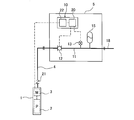
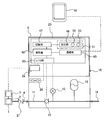
- FIG. 1 is a schematic view showing a pump device according to an embodiment of the present invention.
- FIG. 2 is a diagram showing details of the pump device shown in FIG.
- the pump device includes a submersible pump unit 1 that can be installed in water such as in a well and a land unit 5 that is connected to the submersible pump unit 1 via a suction pipe 4. I have.
- the submersible pump unit 1 includes a pump 2 having an impeller (not shown) and an electric motor 3 that rotates the pump 2. When the electric motor 3 is driven, the pump 2 rotates and water is sent to the land unit 5 through the suction pipe 4.
- Land unit 5 is located on the ground.
- the land unit 5 detects that the control unit 10 that controls the operation of the submersible pump unit 1, the water pipe 11 connected to the suction pipe 4, and the flow rate of water flowing through the water pipe 11 has decreased to a predetermined value.
- a pressure sensor 13 that measures the discharge side pressure of the pump 2.
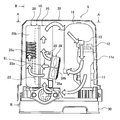
- FIG. 3 is a front view showing components of the land unit 5.
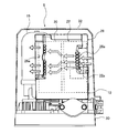
- 4 is a cross-sectional view taken along line AA of FIG. 5 is a cross-sectional view taken along line BB in FIG.
- FIG. 6 is a rear view showing components of the land unit 5.
- the flow switch 12 and the pressure sensor 13 are connected to the water distribution pipe 11, and the pressure sensor 13 is provided on the downstream side of the flow switch 12. More specifically, a part of the water distribution pipe 11 constitutes a casing 11a, and the detection part of the flow switch 12 and the sensor part of the pressure sensor 13 are accommodated in the casing 11a.
- One end of the water distribution pipe 11 is connected to the suction pipe 4, and the other end is connected to the discharge pipe 18.
- a water supply device 19 such as a water tap is connected to the discharge pipe 18.
- a check valve 21 is attached to the suction pipe 4. The check valve 21 is provided to prevent a back flow of water when the pump 2 is stopped.
- the land unit 5 further includes a pressure tank 15 for holding the discharge side pressure of the pump 2.
- the pressure tank 15 is connected to the water distribution pipe 11 and is provided on the downstream side of the pressure sensor 13.
- the pressure tank 15 has a rubber bladder inside the pressure vessel. When the discharge side pressure of the pump 2 increases, the air outside the bladder is compressed and water is stored in a pressurized state. When the pressure in the water distribution pipe 11 decreases, the water held in the bladder is pushed into the water distribution pipe 11 by the compressed air. In this way, even if the pump 2 is stopped, water is supplied from the pressure tank 15 to the water distribution pipe 11 for a while.
- the control unit 10 includes an inverter 22 that can change the speed of the electric motor 3 and a control unit 20 that controls the operation of the inverter 22.
- the inverter 22 is connected to the control unit 20.
- the control unit 20 controls the rotational speed of the electric motor 3, that is, the rotational speed of the pump 2 by controlling the switching operation of a power element 22 a (for example, a switching element such as an IGBT) constituting the inverter 22.
- a power element 22 a for example, a switching element such as an IGBT
- the flow switch 12 and the pressure sensor 13 are connected to the control unit 20 via a signal line.
- the control unit 20 temporarily increases the rotational speed of the pump 2 and stores the pressure in the pressure tank 15 before pump 2. Stop operation.
- the control unit 20 starts the pump 2.
- the control unit 10 further includes a plurality of heat radiation fins 25 close to the control unit 20 and the inverter 22 and a protective cover 26 that covers the control unit 20 and the inverter 22.
- a plurality of ventilation holes 26 a are formed on both side surfaces 26 b and 26 c of the protective cover 26.
- Each ventilation hole 26a is composed of a plurality of slits.
- the number, shape, and location of the ventilation holes 26a are not limited to this embodiment.
- the ventilation hole 26 a may be formed on the lower surface or the upper surface of the protective cover 26.
- the land unit 5 further includes a fan 28 for cooling the inverter 22.
- the fan 28 includes a blade 28 a for forming a flow of air and a rotating shaft 28 b to which the blade 28 a is fixed, and is disposed between the heat radiation fin 25 and the water distribution pipe 11.
- the fan 28 is close to one of the plurality of ventilation holes 26a. More specifically, the fan 28 is close to one of the ventilation holes 26 a provided on both side surfaces 26 b and 26 c of the protective cover 26.
- the ventilation hole 26a is composed of a plurality of slits, but the number, shape, and arrangement location of the slits are not limited to the present embodiment.
- the fan 28 is disposed between one of the plurality of ventilation holes 26 a and the casing 11 a of the water distribution pipe 11.
- the inverter 22 is disposed on the back side of the heat radiation fin 25, and the fan 28 faces the heat radiation fin 25.
- the power element 22 a serving as a heat generation source is disposed so as to face the fan 28 via the radiation fin 25.
- the land unit 5 includes a unit base 30, and the control unit 10, the water pipe 11, and the pressure tank 15 are placed on the unit base 30.
- the land unit 5 includes a unit cover 32 that covers its constituent elements. Components such as the control unit 10, the water distribution pipe 11, the pressure tank 15, the flow switch 12, the pressure sensor 13, and the fan 28 are covered with this unit cover 32.
- a lower end of the unit cover 32 is connected to the unit base 30, and the above-described components are arranged in a space formed between the unit cover 32 and the unit base 30.
- the fan 28 is fixed to the heat radiation fin 25. More specifically, the fixing tool 29 is fixed to the heat radiating fin 25, and the fan 28 is fixed to the heat radiating fin 25 by the fixing tool 29.
- the fan 28 is inclined upward with respect to the horizontal direction. The fan 28 arranged in this way can form a rising air flow while in contact with the radiation fins 25.
- the plurality of heat radiation fins 25 protrude toward the water distribution pipe 11 (specifically, the casing 11a) and extend in the vertical direction. Since the fan 28 is inclined upward, as shown in FIGS. 3 and 6, the air sent from the fan 28 forms a flow that rises along the direction in which the radiating fins 25 extend (that is, the vertical direction). To do.
- the fan 28 is attached to the lower part of the radiation fin 25. According to such an arrangement, the air sent from the fan 28 can come into contact with a wide area of the radiation fin 25.
- the water distribution pipe 11 including the casing 11 a is made of metal, and the water pumped from the pump 2 flows in the water distribution pipe 11, so that the surface temperature of the water distribution pipe 11 is particularly a component of the land unit 5. Low.
- the air whose temperature has risen due to heat removal from the radiation fins 25 is effectively cooled by contacting the water distribution pipe 11.
- the cooled air returns to the fan 28 and is blown out from the fan 28 again.
- the air blown out from the fan 28 circulates through the heat radiation fins 25 and the water distribution pipe 11 in this order, and forms a circulation flow as shown in FIG. 3 in the internal space of the unit cover 32.
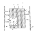
- FIG. 7 is a schematic diagram showing the positional relationship between the protective cover 26 and the fan 28.
- the fan 28 is close to one of the side surfaces 26 b and 26 c of the protective cover 26.
- the fan 28 since the casing 11 a of the water distribution pipe 11 is disposed on the left side of the protective cover 26, the fan 28 is close to the left side surface 26 b of the protective cover 26.
- the fan 28 may be close to the right side surface 26 c of the protective cover 26.
- a part of the air blown out from the fan 28 collides with the side surface of the unit cover 32 in the immediate vicinity of the fan 28, and its traveling direction can be changed. This air flows into the protective cover 26 through the ventilation holes 26a formed in the left side surface 26b of the protective cover 26 (see FIGS. 3 to 5).
- the air flowing in the protective cover 26 contacts the inverter 22 and directly cools the inverter 22.
- the air whose temperature has risen due to the removal of heat from the inverter 22 flows out of the protective cover 26 through the ventilation holes 26a formed in the other side surface 26c of the protective cover 26 (see FIG. 5).
- the air when the fan 28 is operated, the air rises along the heat radiation fins 25 and forms a first air flow that cools the inverter 22. Further, a part of the air passes through the protective cover 26 to form a second air flow that cools the inverter 22. Both of the first air flow and the second air flow are cooled by the water distribution pipe 11 and blown out of the fan 28 again.
- the air flow not only indirectly cools the inverter 22 via the heat radiation fins 25 but also enters the control unit 10 through the ventilation holes 26a to directly cool the inverter 22.
- the fan 28 is disposed between the power element 22a of the inverter 22 and the casing 11a of the water distribution pipe 11, the power element 22a that is a heat source can be effectively cooled.
- special parts and special processing for cooling the inverter 22 are not required, and the inverter 22 can be efficiently cooled with a simple structure.
- the pump device further includes a display 49 that displays operation information including the operation of the fan 28.
- the control unit 20 includes a setting unit 46, a storage unit 47, a calculation unit 48, an I / O unit 50, and an operation panel 51.
- the operation panel 51 functions as a human interface.
- Various setting values relating to operation control of the pump 2 are input to the setting unit 46.
- the setting unit 46 and the display device 49 are provided on the operation panel 51.
- the display device 49 may be a liquid crystal panel, and the setting unit 46 may be a touch panel type operation device.
- the display device 49 is attached to the control unit 20, but the display device 49 may be arranged away from the control unit 20. Further, the display unit 49 may have a configuration in which a liquid crystal panel and a 7-segment LED or an indicator lamp are combined.
- the storage unit 47 stores the operation history of the fan 28 and the like.
- a CPU is used as the calculation unit 48.
- the display 49 functions as a human interface and displays operation information including the operation of the fan 28. The user can erase the display on the display unit 49 by pressing the clear button 53 on the setting unit 46.
- FIG. 9 is a diagram showing details of the storage unit 47.
- the storage unit 47 includes a nonvolatile storage area 47 a configured from a nonvolatile memory and a volatile storage area 47 b configured from a volatile memory.
- the non-volatile storage area 47a is an area for storing an operation history of the fan 28, various set values necessary for the operation of the pump 2, a failure history, an operation history, and the like.
- the volatile storage area 47b is an area for storing the operation of the fan 28, the pressure signal, the pump rotation speed, the current value, a failure, an alarm, and the like.
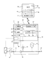
- FIG. 10 is a diagram showing another embodiment of the pump device.
- an external display device 61 is further provided.
- the control unit 20 further includes a communication unit 60.
- the control unit 20 is connected to the external display 61 by wired communication or wireless communication.
- a general-purpose terminal device such as a smartphone, a mobile phone, a personal computer, a tablet, or a dedicated terminal device such as a remote monitor is adopted.
- the display unit 49 is a simple display unit such as a 7-segment LED or an indicator lamp
- the external display unit 61 is a high-function display unit using a liquid crystal screen and a touch input method or a push button method for the liquid crystal screen. . Since the external display 61 has a much larger amount of information that can be displayed than the simple display 49, a user who is unfamiliar with the pump device is misunderstood by displaying that the fan 28 is operating on the external display 61. It is possible to recognize that the fan 28 is operating without doing so.
- the pump device may be installed in an electrically noisy environment such as a machine room or pump room.
- a display unit composed of a 7-segment LED, an indicator lamp, a mechanical push button, etc., which is more resistant to electrical noise than a liquid crystal display or a touch panel is used.
- the pump device can be installed in an environment with a lot of electrical noise.
- the user can display that the fan 28 is operating using dedicated application software. Therefore, it is possible to provide a display of the operation of the fan 28 according to the level of the user by preparing and using a plurality of dedicated application software.
- FIG. 11 is a view showing still another embodiment of the pump device.
- the display unit 49 is not provided in the control unit 20, and only the external display unit (high function display unit) 61 is provided instead.
- Other configurations are the same as those of the embodiment shown in FIG. According to the embodiment shown in FIG. 11, since it is not necessary to provide the display device itself in the pump device, the cost of the entire pump device can be further reduced.
- FIG. 12 is a view showing still another embodiment of the pump device.
- a display device 49 is a simple display device such as a 7-segment LED or an indicator lamp.
- the communication unit 60 is connected to an external display 65 provided in a maintenance management company or an administrator room via a public line.
- the control unit 20 determines that the fan 28 is operating, and the external display device 65 periodically communicates with the control unit 20 through a public line to inquire of the control unit 20 whether the fan 28 is operating. .
- the external display 65 displays the operation of the fan 28.
- the external display 65 may additionally display the operation of the fan 28 in other information.
- the control unit 20 of the present embodiment does not include the clear button 53 shown in FIG. 8, and instead, the external display 65 includes a clear button 66 as shown in FIG. When the user presses the clear button 66, the display of the operation of the fan 28 displayed on the external display 65 is deleted.
- FIG. 13 is a view showing still another embodiment of the pump device.
- the basic configuration of the control unit 20 of the present embodiment is the same as the configuration of the control unit 20 of the embodiment shown in FIG. 11, but the control unit 20 includes a control unit side antenna unit 67 instead of the communication unit 60. And an integrated circuit 68 connected to the control unit side antenna unit 67 is different.
- the integrated circuit 68 is electrically connected to a storage unit 47 having a nonvolatile storage area 47a and a volatile storage area 47b.
- the control part 20 of this embodiment is not provided with the indicator 49, you may provide the indicator 49 in the control part 20.
- the external display 70 includes a display-side antenna unit 71 that transmits and receives radio waves, a data reader 74 that reads data received by the display-side antenna unit 71, and data read by the data reader 74 (for example, the operation of the fan 28). , An operation state of the pump 2, a discharge pressure, and the like), a data reader 74, a display-side antenna unit 71, and a battery 73 that supplies power to the display unit 72.
- the external display device 70 may be a general-purpose terminal device such as a smartphone, a mobile phone, a personal computer, or a tablet, or may be a dedicated terminal device such as a remote monitor.
- a general-purpose terminal device such as a smartphone
- the cost of producing a dedicated display device can be reduced, so that the cost of the pump device can be reduced.
- the fan 28 can be operated even for a user who does not have expertise in a pump device such as an apartment or building manager. Therefore, it is possible to provide a pump device that can easily inform the user that the operation is being performed.
- the external display unit 70 is connected to the control unit 20 by a near field communication (NFC) technology. More specifically, when the display-side antenna unit 71 generates radio waves while the external display unit 70 is close to the control unit 20, the control-side antenna unit 67 receives the radio waves, and the control-unit-side antenna unit 67. Converts radio waves into electric power. This electric power is supplied to the integrated circuit 68 and the storage unit 47 to drive the integrated circuit 68 and the storage unit 47.
- the integrated circuit 68 reads the data stored in the storage unit 47 and sends the data to the control unit side antenna unit 67.
- the control unit side antenna unit 67 transmits radio waves together with data to the display unit side antenna unit 71.
- the data reader 74 reads data received by the display-side antenna unit 71 and causes the display unit 72 to display the data.
- the external display 70 is provided with a clear button 66 for deleting the display of the operation of the fan 28.
- the clear button 66 of this embodiment is a virtual button that appears on the screen of the display unit 72, but the clear button 66 may be a mechanical button provided outside the display unit 72.
- the control unit 20 of the present embodiment does not include a clear button, the control unit 20 may be provided with a clear button. Note that operation restrictions may be provided for these operations. Specifically, a clear button 66 is provided on the external display 70 used mainly by the user, and a reset button 52 is provided on the control unit 20 used mainly by maintenance personnel.
- wireless communication is performed between the external display 70 and the control unit 20, and data including the operation of the fan 28 stored in the storage unit 47 is transferred from the control unit 20 to the external display 70.
- Sent According to the present embodiment, even when the power of the pump device is not turned on, the control unit side antenna unit 67 generates power from the radio wave emitted from the external display device 70 and drives the integrated circuit 68 and the storage unit 47. Can do. Therefore, even when power is not supplied to the control unit 20 during maintenance of the pump device or the like, the external display 70 acquires data including the operation of the fan 28 from the storage unit 47 of the control unit 20 and stores the data. Can be displayed.
- control unit 20 fails, it must be replaced with a new control unit 20. Even when the old control unit 20 that has failed is not turned on when the control unit 20 is replaced, in the present embodiment, data related to the operation of the fan 28 of the old control unit 20 is stored in the storage unit 47 of the new control unit 20. It is possible to inherit. Specifically, the data in the storage unit 47 of the old control unit 20 is displayed on the external display 70, and the maintenance person inputs from the operation unit of the new control unit 20 while confirming the display. The storage unit 47 may store the data, or the data of the old control unit 20 may be acquired by the external display unit 70 and communicated from the external display unit 70 to the storage unit 47 of the new control unit 20. May be written.
- the control unit 20 fails in a state where the power is not turned on, the data stored in the non-volatile storage area 47a can be inherited to the storage unit 47 of the new control unit 20, so that the operation data of the fan 28 is lost. None. This means that the operation history of the fan 28 can be displayed even after the pump device starts automatic operation in the new control unit 20.
- the user and the maintenance staff simply acquire the information including the operation of the fan 28 from the storage unit 47 only by bringing the external display 70 close to the control unit 20. Is possible.
- NFC Near field communication
- NFC employed in this embodiment is a technology that enables mutual communication only at a short distance of several centimeters. Therefore, in order to display the operation of the fan 28 and other various information on the external display 70, it is necessary for the user and maintenance personnel to bring the external display 70 close to the control unit 20. This means that when operating the external display 70, the user and maintenance personnel are near the pump device. Therefore, the user or the maintenance staff operates the external display unit 70 while visually observing the pump device, which leads to preventing an unexpected operation of the pump device due to an erroneous operation. Further, in a site where a plurality of pump devices are installed, communication is possible only at a short distance of the pump device for which the operation of the fan 28 is desired to be displayed. Can be prevented from being displayed erroneously.
- FIG. 14 is a diagram showing still another embodiment of the pump device.
- the control unit 20 includes a communication unit 60.
- the communication unit 60 is connected to the communication unit 76 of the external display 75 by wired communication or wireless communication.
- the external display 75 includes a control unit 80, and the control unit 80 includes a communication unit 76, a storage unit 77, a calculation unit 78, and a display unit 79.
- the control unit 20 may include a display device 49.
- the storage unit 77 has the configuration shown in FIG.
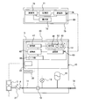
- FIG. 15 is a view showing still another embodiment of the pump device.
- the control unit 20 is not provided with a display, and instead, the external display 75 is provided with a display unit 79 and a setting unit 82.
- the external display 75 is provided with a display unit 79 and a setting unit 82.
- Other configurations are the same as those of the embodiment shown in FIG.
- the operating state of the fan 28 is displayed on the display unit 79, and other various setting values are input through the setting unit 82 of the external display device 75.
- the present invention can be used for a pump device provided with a submersible pump unit.
Landscapes
- Engineering & Computer Science (AREA)
- Mechanical Engineering (AREA)
- General Engineering & Computer Science (AREA)
- Physics & Mathematics (AREA)
- Thermal Sciences (AREA)
- Structures Of Non-Positive Displacement Pumps (AREA)
- Details Of Reciprocating Pumps (AREA)
Abstract
本発明は、水中ポンプユニットを備えたポンプ装置に関するものである。 ポンプ装置は、水中ポンプユニット(1)と、陸上ユニット(5)とを備える。陸上ユニット(5)は、放熱フィン(25)を有する制御ユニット(10)と、吸込管(4)に接続された配水管(11)と、放熱フィン(25)に対向するファン(28)とを備えている。制御ユニット(10)は、電動機(3)を変速可能とするインバータ(22)と、インバータ(22)の動作を制御する制御部(20)と、インバータ(22)および制御部(20)を覆う保護カバー(26)とを備えている。保護カバー(26)は複数の通風孔(26a)を有しており、ファン(28)は複数の通風孔(26a)のうちの1つと、配水管(11)との間に配置されている。
Description
本発明は、ポンプ装置に関し、特に、水中ポンプユニットを備えたポンプ装置に関するものである。
井戸内の水を地上に移送するためのポンプ装置が知られている。このタイプのポンプ装置は、井戸内に配置された水中ポンプユニットと、吸込管を通じて水中ポンプユニットに接続された陸上ユニットとを備えている。陸上ユニットは、水中ポンプユニットの電動機を変速可能とするインバータ、該インバータの動作を制御する制御部などの構成要素を備えている。水中ポンプユニットが駆動されると、井戸内の水は吸込管を通じて陸上ユニットに送られ、さらに陸上ユニットに接続された排出管を流れる。
ポンプ装置を運転すると、水中ポンプユニットの運転に伴ってインバータが発熱し、インバータの温度は非常に高くなる。そこで、インバータを冷却するため、インバータに設けられた放熱フィンと、放熱フィンに気流を送るファンとを備えたポンプ装置が知られている(例えば特許文献1参照)。
特許文献1のポンプ装置は、放熱フィンおよびファンを取り囲む筒部を備えている。ファンが回転すると、空気はファンを通じて筒部内を流れ、放熱フィンを介してインバータを冷却する。しかしながら、このような構成では、熱伝導性を有する筒部を必要とするため、インバータを冷却するために必要な部品の数が多くなり、ポンプ装置の構造が複雑になる。また、放熱フィンおよびファンを取り囲むための筒部の形状も複雑になる。さらに、筒部内を流れる空気は、放熱フィンのみを介してインバータを冷却するため、冷却効率が低い。
特許文献1のポンプ装置では、筒部をブロック部に面接触させることによって冷却性を向上させているが、ブロック部は、ポンプの運転時に流れる水によって振動するため、ブロック部に接触する筒部も振動し、結果的に、インバータも振動してしまう。
そこで、本発明は、簡易な構造で、効率よくインバータを冷却することができるポンプ装置を提供することを目的とする。
本発明の一態様は、ポンプおよび電動機を備えた水中ポンプユニットと、吸込管を介して前記水中ポンプユニットに接続された陸上ユニットとを備え、前記陸上ユニットは、放熱フィンを有する制御ユニットと、前記吸込管に接続された配水管と、前記放熱フィンに対向するファンとを備え、前記制御ユニットは、前記電動機を変速可能とするインバータと、前記インバータの動作を制御する制御部と、前記インバータおよび前記制御部を覆う保護カバーとを備えており、前記保護カバーは複数の通風孔を有しており、前記ファンは前記複数の通風孔のうちの1つと、前記配水管との間に配置されていることを特徴とするポンプ装置である。
本発明の好ましい態様は、前記ファンは、前記複数の通風孔のうちの1つに近接していることを特徴とする。
本発明の好ましい態様は、前記複数の通風孔は前記保護カバーの両側面に形成されており、前記ファンは、前記保護カバーの両側面のうちの一方に近接していることを特徴とする。
本発明の好ましい態様は、前記インバータのパワー素子は、前記ファンの回転軸の延長線上にあることを特徴とする。
本発明の好ましい態様は、前記ファンは、水平方向に対して上方に傾斜していることを特徴とする。
本発明の好ましい態様は、前記放熱フィンは前記配水管に向かって突出しており、かつ鉛直方向に延びていることを特徴とする。
本発明の好ましい態様は、前記ファンは前記放熱フィンに固定されていることを特徴とする。
本発明の好ましい態様は、前記制御ユニット、前記配水管、および前記ファンを覆うユニットカバーをさらに備えたことを特徴とする。
本発明の好ましい態様は、前記複数の通風孔は前記保護カバーの両側面に形成されており、前記ファンは、前記保護カバーの両側面のうちの一方に近接していることを特徴とする。
本発明の好ましい態様は、前記インバータのパワー素子は、前記ファンの回転軸の延長線上にあることを特徴とする。
本発明の好ましい態様は、前記ファンは、水平方向に対して上方に傾斜していることを特徴とする。
本発明の好ましい態様は、前記放熱フィンは前記配水管に向かって突出しており、かつ鉛直方向に延びていることを特徴とする。
本発明の好ましい態様は、前記ファンは前記放熱フィンに固定されていることを特徴とする。
本発明の好ましい態様は、前記制御ユニット、前記配水管、および前記ファンを覆うユニットカバーをさらに備えたことを特徴とする。
本発明の好ましい態様は、前記ファンが運転していることを表示する表示器をさらに備えていることを特徴とする。
本発明の好ましい態様は、前記制御部は、外部表示器と有線通信または無線通信で接続することができることを特徴とする。
本発明の好ましい態様は、前記制御部は、近距離無線通信(NFC)によって前記外部表示器に接続できることを特徴とする。
本発明の好ましい態様は、前記制御部は、前記外部表示器からの電波を受信して該電波を電力に変換する制御部側アンテナ部と、前記電力によって駆動される集積回路および記憶部とを備えることを特徴とする。
本発明の好ましい態様は、前記制御部は、前記ファンの運転を示すデータを前記記憶部に記憶し、前記集積回路は、前記記憶部から前記データを読み取り、前記制御部側アンテナ部は前記データを前記外部表示器に送信することを特徴とする。
本発明の好ましい態様は、前記制御部は、外部表示器と有線通信または無線通信で接続することができることを特徴とする。
本発明の好ましい態様は、前記制御部は、近距離無線通信(NFC)によって前記外部表示器に接続できることを特徴とする。
本発明の好ましい態様は、前記制御部は、前記外部表示器からの電波を受信して該電波を電力に変換する制御部側アンテナ部と、前記電力によって駆動される集積回路および記憶部とを備えることを特徴とする。
本発明の好ましい態様は、前記制御部は、前記ファンの運転を示すデータを前記記憶部に記憶し、前記集積回路は、前記記憶部から前記データを読み取り、前記制御部側アンテナ部は前記データを前記外部表示器に送信することを特徴とする。
本発明によれば、ファンによって形成される空気の流れは、放熱フィンを介してインバータを間接的に冷却するのみならず、通風孔を通じて制御ユニット内に進入し、インバータを直接冷却することができる。さらに、インバータを冷却するための特殊な部品や特殊な加工は必要なく、簡易な構造でインバータを効率よく冷却することができる。
以下、本発明の実施の形態について、図面を参照して説明する。
図1は本発明の一実施形態に係るポンプ装置を示す模式図である。図2は図1に示すポンプ装置の詳細を示す図である。図1および図2に示すように、ポンプ装置は、井戸内などの水中に設置することができる水中ポンプユニット1と、吸込管4を介して水中ポンプユニット1に接続された陸上ユニット5とを備えている。水中ポンプユニット1は、羽根車(図示しない)を有するポンプ2と、このポンプ2を回転させる電動機3とを備えている。電動機3が駆動されると、ポンプ2が回転し、水は吸込管4を通じて陸上ユニット5に送られる。
図1は本発明の一実施形態に係るポンプ装置を示す模式図である。図2は図1に示すポンプ装置の詳細を示す図である。図1および図2に示すように、ポンプ装置は、井戸内などの水中に設置することができる水中ポンプユニット1と、吸込管4を介して水中ポンプユニット1に接続された陸上ユニット5とを備えている。水中ポンプユニット1は、羽根車(図示しない)を有するポンプ2と、このポンプ2を回転させる電動機3とを備えている。電動機3が駆動されると、ポンプ2が回転し、水は吸込管4を通じて陸上ユニット5に送られる。
陸上ユニット5は地上に配置されている。陸上ユニット5は、水中ポンプユニット1の動作を制御する制御ユニット10と、吸込管4に接続された配水管11と、配水管11を流れる水の流量が所定の値にまで低下したことを検知するフロースイッチ12と、ポンプ2の吐出側圧力を測定する圧力センサ13とを備えている。
図3は陸上ユニット5の構成要素を示す正面図である。図4は図3のA-A線断面図である。図5は図3のB-B線断面図である。図6は陸上ユニット5の構成要素を示す背面図である。フロースイッチ12および圧力センサ13は配水管11に接続されており、圧力センサ13はフロースイッチ12の下流側に設けられている。より具体的には、配水管11の一部はケーシング11aを構成しており、フロースイッチ12の検出部および圧力センサ13のセンサ部はケーシング11a内に収容されている。
配水管11の一端は吸込管4に接続され、他端は排出管18に接続されている。排出管18には水栓などの給水器具19が接続されている。吸込管4には、逆止弁21が取り付けられている。この逆止弁21は、ポンプ2が停止したときの水の逆流を防止するために設けられている。
陸上ユニット5は、ポンプ2の吐出側圧力を保持するための圧力タンク15をさらに備えている。圧力タンク15は配水管11に接続されており、圧力センサ13の下流側に設けられている。圧力タンク15は、その耐圧容器の内部にゴム製のブラダを有している。ポンプ2の吐出側圧力が上昇すると、ブラダの外側の空気は圧縮され、水が加圧状態で貯留される。配水管11内の圧力が低下すると、ブラダに保持された水は圧縮された空気によって配水管11内に押し出される。このようにして、ポンプ2が停止しても、しばらくの間、圧力タンク15から配水管11に水が供給される。
制御ユニット10は、電動機3を変速可能とするインバータ22と、インバータ22の動作を制御する制御部20を備えている。インバータ22は制御部20に接続されている。制御部20は、インバータ22を構成するパワー素子22a(例えば、IGBTなどのスイッチング素子)のスイッチング動作を制御することで、電動機3の回転速度、すなわちポンプ2の回転速度を制御する。
フロースイッチ12および圧力センサ13は信号線を介して制御部20に接続されている。配水管11を流れる水の流量が所定の値にまで低下したことをフロースイッチ12が検出すると、制御部20はポンプ2の回転速度を一時的に上げ、圧力タンク15に蓄圧してからポンプ2の運転を停止させる。ポンプ2の吐出側圧力が所定の始動圧力まで低下したことを圧力センサ13が検出すると、制御部20はポンプ2を始動させる。
制御ユニット10は、制御部20およびインバータ22に近接する複数の放熱フィン25と、制御部20およびインバータ22を覆う保護カバー26とをさらに備えている。保護カバー26の両側面26b,26cには、複数の通風孔26aが形成されている。各通風孔26aは複数のスリットから構成されている。通風孔26aの数、形状、および配置箇所は本実施形態に限定されない。例えば、通風孔26aは保護カバー26の下面や上面にも形成されてもよい。
陸上ユニット5は、インバータ22を冷却するためのファン28をさらに備えている。ファン28は、空気の流れを形成するための羽根28aと、羽根28aが固定された回転軸28bとを備えており、放熱フィン25と配水管11との間に配置されている。ファン28は複数の通風孔26aのうちの1つに近接している。より具体的には、ファン28は、保護カバー26の両側面26b,26cにそれぞれ設けられた通風孔26aのうちの一方に近接している。本実施形態では、通風孔26aは複数のスリットから構成されているが、スリットの数、形状、および配置箇所は本実施形態に限定されない。ファン28は、複数の通風孔26aのうちの1つと、配水管11のケーシング11aとの間に配置されている。インバータ22は、放熱フィン25の裏面側に配置されており、ファン28は放熱フィン25に対向している。特に、発熱源となるパワー素子22aは放熱フィン25を介してファン28に対向して配置されている。
陸上ユニット5はユニットベース30を備えており、制御ユニット10、配水管11、圧力タンク15はユニットベース30の上に載置されている。陸上ユニット5は、その構成要素を覆うユニットカバー32を備えている。制御ユニット10、配水管11、圧力タンク15、フロースイッチ12、圧力センサ13、およびファン28などの構成要素は、このユニットカバー32で覆われている。ユニットカバー32の下端は、ユニットベース30に接続されており、上述した構成要素は、ユニットカバー32とユニットベース30との間に形成された空間内に配置されている。
ファン28は放熱フィン25に固定されている。より具体的には、固定具29が放熱フィン25に固定されており、ファン28はこの固定具29によって放熱フィン25に固定されている。ファン28は水平方向に対して上方に傾斜している。このように配置されたファン28は、放熱フィン25に接触しながら上昇する空気の流れを形成することができる。
ここで、ファン28によって形成される空気の流れについて説明する。ファン28が回転すると、空気はファン28から放熱フィン25およびインバータ22に向かって吐出される。空気は、放熱フィン25に接触することによって、インバータ22から放熱フィン25に伝達した熱を奪う。特に、図3および図4に示すように、パワー素子22aはファン28の回転軸28bの延長線EL上にあるため、ファン28から送られた空気はパワー素子22aを効果的に冷却することができる。
複数の放熱フィン25は配水管11(具体的には、ケーシング11a)に向かって突出しており、かつ鉛直方向に延びている。ファン28は上方に傾斜しているので、図3および図6に示すように、ファン28から送られた空気は、放熱フィン25の延びる方向(すなわち、鉛直方向)に沿って上昇する流れを形成する。本実施形態では、ファン28は放熱フィン25の下部に取り付けられている。このような配置によれば、ファン28から送られた空気は、放熱フィン25の広い領域に接触することができる。
放熱フィン25を通過した空気の流れは、ユニットカバー32の上面に衝突してその進行方向を変えられ、配水管11に接触する。ケーシング11aを含む配水管11は金属から構成されており、配水管11内にはポンプ2から揚水された水が流れているため、配水管11の表面温度は陸上ユニット5の構成要素の中でも特に低い。放熱フィン25から熱を奪って温度が上昇した空気は、配水管11に接触することによって効果的に冷却される。冷却された空気はファン28に戻り、ファン28から再び吹き出される。
このように、ファン28から吹き出された空気は、放熱フィン25および配水管11をこの順に循環し、ユニットカバー32の内部空間に、図3に示すような循環流を形成する。
図7は、保護カバー26とファン28との位置関係を示す模式図である。図7に示すように、ファン28は保護カバー26の両側面26b,26cのうちの一方に近接している。図7に示す例では、配水管11のケーシング11aが保護カバー26の左側に配置されているので、ファン28は、保護カバー26の左側面26bに近接している。配水管11のケーシング11aが保護カバー26の右側に配置されている場合は、ファン28は、保護カバー26の右側面26cに近接されてもよい。ファン28から吹き出された空気の一部は、ファン28の直ぐ近くのユニットカバー32の側面に衝突し、その進行方向を変えられる。この空気は保護カバー26の左側面26bに形成された通風孔26aを通じて保護カバー26内に流入する(図3乃至図5参照)。
保護カバー26内を流れる空気は、インバータ22に接触し、インバータ22を直接冷却する。インバータ22から熱を奪って温度が上昇した空気は、保護カバー26の他方の側面26cに形成された通風孔26aを通じて保護カバー26から流出する(図5参照)。
本実施形態によれば、ファン28が運転されると、空気は放熱フィン25に沿って上昇し、インバータ22を冷却する第1の空気流れを形成する。さらに、空気の一部は保護カバー26内を通過してインバータ22を冷却する第2の空気流れを形成する。これら第1の空気流れおよび第2の空気流れは、いずれも配水管11によって冷却され、再びファン28から吹き出される。
このように、空気の流れは、放熱フィン25を介して間接的にインバータ22を冷却するのみならず、通風孔26aを通じて制御ユニット10内に進入し、インバータ22を直接冷却することができる。特に、ファン28はインバータ22のパワー素子22aと配水管11のケーシング11aとの間に配置されているため、発熱源であるパワー素子22aを効果的に冷却することができる。さらに、本実施形態によれば、インバータ22を冷却するための特殊な部品や特殊な加工は必要なく、簡易な構造でインバータ22を効率よく冷却することができる。
次に、上述したポンプ装置のより詳細な構成について図8を参照して説明する。図8に示すように、ポンプ装置は、ファン28の運転を含む運転情報を表示する表示器49をさらに備えている。制御部20は、設定部46、記憶部47、演算部48、I/O部50、および運転パネル51を備えている。運転パネル51は、ヒューマンインターフェースとして機能する。設定部46には、ポンプ2の運転制御に関する各種設定値が入力される。設定部46および表示器49は、運転パネル51に設けられている。表示器49は液晶パネルであり、設定部46はタッチパネル式操作器でもよい。本実施形態では、表示器49は制御部20に取り付けられているが、表示器49は制御部20から離れて配置されてもよい。また、表示器49は液晶パネルと7セグメントLEDや表示灯を組み合わせた構成でもよい。
記憶部47は、ファン28の運転の履歴などを記憶する。演算部48としては、CPUが使用される。表示器49は、ヒューマンインターフェースとして機能し、ファン28の運転を含む運転情報を表示する。ユーザーは、設定部46上のクリアボタン53を押すことにより、表示器49での表示を消去することができる。
図9は記憶部47の詳細を示す図である。図9に示すように、記憶部47は、不揮発性メモリから構成された不揮発性記憶領域47aと、揮発性メモリから構成された揮発性記憶領域47bを備えている。不揮発性記憶領域47aは、ファン28の運転の履歴、ポンプ2の運転に必要な各種設定値、故障履歴、運転履歴などを記憶する領域である。揮発性記憶領域47bは、ファン28の運転、圧力信号、ポンプ回転数、電流値、故障、警報などを記憶する領域である。
図10はポンプ装置の他の実施形態を示す図である。本実施形態では、表示器49に加えて、外部表示器61がさらに設けられている。図10に示すように、制御部20は通信部60をさらに備えている。制御部20は有線通信または無線通信によって外部表示器61に接続されている。外部表示器61として、例えばスマートフォンや携帯電話、パソコン、タブレットの汎用端末機器または遠隔監視器などの専用端末機器が採用される。本実施形態では、表示器49は7セグメントLEDや表示灯などの簡易な表示器であり、外部表示器61は液晶画面と液晶画面のタッチ入力方式や押圧ボタン方式用いた高機能表示器である。簡易な表示器49に比べて外部表示器61は表示できる情報量が格段に多いため、外部表示器61にファン28が運転していることを表示することによって、ポンプ装置に不慣れなユーザーは誤解することなく、ファン28が運転していることを認識することが出来る。
ポンプ装置は機械室やポンプ室などの電気的なノイズの多い環境に設置されることがある。本実施形態によれば、ポンプ装置に組み込まれる表示器49として、液晶表示やタッチパネルよりも電気的ノイズに強い7セグメントLEDや表示灯、機械的な押圧ボタンなどにて構成された表示器を使用することにより、外部環境から発生される電気的なノイズにより外部表示器61の液晶表示やタッチパネル操作に異常が発生した場合でも、表示器49によりポンプ装置の運転に必要な最低限度の表示や操作を行うことが可能なため、ポンプ装置を電気的ノイズの多い環境下にも設置することができる。さらに、外部表示器61として、スマートフォン、携帯電話、パソコン、タブレットなどの汎用端末機器を使用すると、ユーザーは専用のアプリケーションソフトウエアを用いて、ファン28が運転していることを表示させることができるため、専用のアプリケーションソフトウエアを複数用意し使い分けることによりユーザーのレベルに沿ったファン28の運転の表示を提供することが可能である。
図11はポンプ装置のさらに他の実施形態を示す図である。本実施形態では、制御部20に表示器49は設けられていなく、代わりに外部表示器(高機能表示器)61のみが設けられる。その他の構成は、図10に示す実施形態と同様である。図11に示す実施形態によれば、ポンプ装置には表示器自体を設ける必要がなくなるので、ポンプ装置全体のコストを更に下げることが可能である。
図12はポンプ装置のさらに他の実施形態を示す図である。図12において、表示器49は7セグメントLEDや表示灯などの簡易な表示器である。通信部60は公衆回線を介して保守管理会社または管理人室に設けられた外部表示器65に接続されている。制御部20は、ファン28が運転していることを判断し、外部表示器65は制御部20に公衆回線を通じて定期的に通信し、ファン28が運転しているか否かを制御部20に問い合わせる。そして、ファン28が運転している場合は、外部表示器65はファン28の運転を表示する。外部表示器65はファン28の運転を他の情報に追加的に表示してもよい。
本実施形態の制御部20は、図8に示すクリアボタン53を備えていなく、代わりに、外部表示器65は、図12に示すように、クリアボタン66を備えている。ユーザーがこのクリアボタン66を押すと、外部表示器65上に表示されているファン28の運転の表示が消去される。
図13はポンプ装置のさらに他の実施形態を示す図である。本実施形態の制御部20の基本的構成は図11に示す実施形態の制御部20の構成と同じであるが、制御部20が通信部60に代えて、制御部側アンテナ部67を備えている点、および制御部側アンテナ部67に接続された集積回路68を備えている点で異なっている。集積回路68は、不揮発性記憶領域47a、揮発性記憶領域47bを有する記憶部47に電気的に接続されている。なお、本実施形態の制御部20は表示器49を備えていないが、制御部20に表示器49を設けてもよい。
外部表示器70は、電波を送受信する表示器側アンテナ部71と、表示器側アンテナ部71で受信したデータを読み取るデータリーダー74と、データリーダー74によって読み取られたデータ(例えば、ファン28の運転、ポンプ2の運転状態、吐出し圧力など)を表示する表示部72と、データリーダー74、表示器側アンテナ部71、および表示部72に電力を供給するバッテリー73とを備えている。外部表示器70として、例えばスマートフォンや携帯電話、パソコン、タブレット等の汎用端末機器でもよく、遠隔監視器などの専用の端末機器でもよい。特に、スマートフォンなどの汎用端末機器を外部表示器として使用すれば、専用の表示器を制作するコストが削減できるので、ポンプ装置のコストを下げることができる。また、複数のユーザーが個々の汎用端末機器にファン28の運転を表示させることができるので、マンションやビルの管理人のようなポンプ装置に関する専門知識のないユーザーに対しても、ファン28が運転していることを分かり易く知らせることができるポンプ装置を安価に提供することができる。
外部表示器70は、近距離無線通信(NFC:Near Field Communication)の技術によって制御部20と接続される。より具体的には、外部表示器70を制御部20に近づけた状態で、表示器側アンテナ部71が電波を発生すると、その電波を制御部側アンテナ部67が受け取り、制御部側アンテナ部67は電波を電力に変換する。この電力は集積回路68および記憶部47に供給されてこれら集積回路68および記憶部47を駆動する。集積回路68は記憶部47に記憶されている上記データを読み取り、制御部側アンテナ部67にデータを送る。制御部側アンテナ部67は、データとともに電波を表示器側アンテナ部71に送信する。データリーダー74は、表示器側アンテナ部71が受信したデータを読み取り、そのデータを表示部72に表示させる。
外部表示器70は、ファン28の運転の表示を消去するためのクリアボタン66を備えている。ユーザーがこのクリアボタン66を押すと、表示部72に表示されているファン28の運転の表示が消去される。本実施形態のクリアボタン66は、表示部72の画面上に現れる仮想的なボタンであるが、クリアボタン66は表示部72の外に設けられた機械的なボタンであってもよい。本実施形態の制御部20はクリアボタンを備えていないが、制御部20にクリアボタンを設けてもよい。なお、これらの操作には、操作制限を設けてもよい。具体的には、ユーザーが主に使用する外部表示器70にクリアボタン66を設け、メンテナンス員が主に使用する制御部20にリセットボタン52を設ける。このように制御部20にのみリセットボタン52を設けることで、ユーザーのリセットボタン52の誤操作を防ぐことができる。パスワード等の複雑な使用制限の解除方法ではなく、外部表示器70を設けることで、ユーザーの誤操作によるファン28の運転のクリアを防止することができる。
本実施形態では、外部表示器70と制御部20との間で無線通信が行われ、記憶部47に記憶されているファン28の運転などを含むデータは、制御部20から外部表示器70に送られる。本実施形態によれば、ポンプ装置の電源が入っていない場合でも、制御部側アンテナ部67は外部表示器70から発せられる電波から電力を発生し、集積回路68および記憶部47を駆動することができる。したがって、ポンプ装置のメンテンナンス中などにおいて制御部20に電力が供給されていないときでも、外部表示器70は、制御部20の記憶部47からファン28の運転を含むデータを取得し、該データを表示することができる。
制御部20が故障した場合には新制御部20に交換する必要がある。この制御部20の交換時に、故障した旧制御部20はすでに電源が入らない状態においても、本実施形態では、旧制御部20のファン28の運転に関するデータを新制御部20の記憶部47に継承することが可能となる。具体的には、旧制御部20の記憶部47の該データを外部表示器70にて表示し、その表示を確認しながらメンテナンス員が新制御部20の操作部より入力し、新制御部20の記憶部47に該データを記憶させてもよいし、旧制御部20の該データを外部表示器70にて取得し、外部表示器70から新しい制御部20の記憶部47へと通信手段にて書き込んでもよい。制御部20が電源が入らない状態で故障しても、不揮発性記憶領域47aに記憶されているデータを新制御部20の記憶部47に継承できるので、ファン28の運転のデータが損失されることない。これは、ポンプ装置が新制御部20にて自動運転を開始した後でも、ファン28の運転の履歴を表示することができることを意味する。
本実施形態によれば、ポンプ装置に電力が供給されていないときでも、ユーザーやメンテナンス員が外部表示器70を制御部20に近づけるだけで、記憶部47からファン28の運転を含む情報を取得することが可能である。
本実施形態で採用される近距離無線通信(NFC:Near Field Communication)は、数cmの近距離でのみ相互通信が可能な技術である。したがって、外部表示器70にファン28の運転やその他の各種情報を表示させるためには、ユーザーやメンテナンス員は外部表示器70を制御部20に近づける必要がある。このことは、外部表示器70を操作するときは、ユーザーやメンテナンス員はポンプ装置の近くにいることを意味する。したがって、ユーザーやメンテナンス員はポンプ装置を目視しながら外部表示器70を操作することになり、誤操作に起因したポンプ装置の予期しない動作を防止することに繋がる。また、複数のポンプ装置が設置された現場では、ファン28の運転を表示したいポンプ装置の近距離でのみ通信可能となる為、無線通信にてよくある意図しない別のポンプ装置のファン28の運転を表示してしまうという誤表示を防止することが出来る。
図14はポンプ装置のさらに他の実施形態を示す図である。本実施形態では、制御部20は通信部60を備えている。通信部60は、有線通信または無線通信によって外部表示器75の通信部76に接続されている。外部表示器75は制御部80を備えており、制御部80は通信部76、記憶部77、演算部78、および表示部79を備えている。制御部20は、表示器49を備えていてもよい。また、記憶部77は記憶部47と同様に図9の構成とする。
図15はポンプ装置のさらに他の実施形態を示す図である。本実施形態では、制御部20には表示器は設けられておらず、代わりに、外部表示器75に表示部79と設定部82が設けられている。その他の構成は図14に示す実施形態と同様である。本実施形態では、ファン28の運転の状態は表示部79に表示され、その他各種設定値の入力は、外部表示器75の設定部82を通じて行われる。
上述した実施形態は、本発明が属する技術分野における通常の知識を有する者が本発明を実施できることを目的として記載されたものである。上記実施形態の種々の変形例は、当業者であれば当然になしうることであり、本発明の技術的思想は他の実施形態にも適用しうる。したがって、本発明は、記載された実施形態に限定されることはなく、特許請求の範囲によって定義される技術的思想に従った最も広い範囲とすべきである。
本発明は、水中ポンプユニットを備えたポンプ装置に利用可能である。
1 水中ポンプユニット
2 ポンプ
3 電動機
4 吸込管
5 陸上ユニット
10 制御ユニット
11 配水管
11a ケーシング
12 フロースイッチ
13 圧力センサ
15 圧力タンク
18 排出管
19 給水器具
20,80 制御部
21 逆止弁
22 インバータ
25 放熱フィン
26 保護カバー
26a 通風孔
28 ファン
28a 羽根
28b 回転軸
30 ユニットベース
32 ユニットカバー
46 設定部
47 記憶部
47a 不揮発性記憶領域
47b 揮発性記憶領域
48 演算部
49 表示部
50 I/O部
51 運転パネル
52 リセットボタン
53,66 クリアボタン
60 通信部
61,65,70,75 外部表示器
67 制御部側アンテナ部
68 集積回路
71 表示器側アンテナ部
72 表示部
73 バッテリー
74 データリーダー
79 表示部
82 設定部
2 ポンプ
3 電動機
4 吸込管
5 陸上ユニット
10 制御ユニット
11 配水管
11a ケーシング
12 フロースイッチ
13 圧力センサ
15 圧力タンク
18 排出管
19 給水器具
20,80 制御部
21 逆止弁
22 インバータ
25 放熱フィン
26 保護カバー
26a 通風孔
28 ファン
28a 羽根
28b 回転軸
30 ユニットベース
32 ユニットカバー
46 設定部
47 記憶部
47a 不揮発性記憶領域
47b 揮発性記憶領域
48 演算部
49 表示部
50 I/O部
51 運転パネル
52 リセットボタン
53,66 クリアボタン
60 通信部
61,65,70,75 外部表示器
67 制御部側アンテナ部
68 集積回路
71 表示器側アンテナ部
72 表示部
73 バッテリー
74 データリーダー
79 表示部
82 設定部
Claims (13)
- ポンプおよび電動機を備えた水中ポンプユニットと、
吸込管を介して前記水中ポンプユニットに接続された陸上ユニットとを備え、
前記陸上ユニットは、
放熱フィンを有する制御ユニットと、
前記吸込管に接続された配水管と、
前記放熱フィンに対向するファンとを備え、
前記制御ユニットは、
前記電動機を変速可能とするインバータと、
前記インバータの動作を制御する制御部と、
前記インバータおよび前記制御部を覆う保護カバーとを備えており、
前記保護カバーは複数の通風孔を有しており、前記ファンは前記複数の通風孔のうちの1つと、前記配水管との間に配置されていることを特徴とするポンプ装置。 - 前記ファンは、前記複数の通風孔のうちの1つに近接していることを特徴とする請求項1に記載のポンプ装置。
- 前記複数の通風孔は前記保護カバーの両側面に形成されており、
前記ファンは、前記保護カバーの両側面のうちの一方に近接していることを特徴とする請求項1または2に記載のポンプ装置。 - 前記インバータのパワー素子は、前記ファンの回転軸の延長線上にあることを特徴とする請求項1乃至3のいずれか一項に記載のポンプ装置。
- 前記ファンは、水平方向に対して上方に傾斜していることを特徴とする請求項1乃至4のいずれか一項に記載のポンプ装置。
- 前記放熱フィンは前記配水管に向かって突出しており、かつ鉛直方向に延びていることを特徴とする請求項5に記載のポンプ装置。
- 前記ファンは前記放熱フィンに固定されていることを特徴とする請求項1乃至6のいずれか一項に記載のポンプ装置。
- 前記制御ユニット、前記配水管、および前記ファンを覆うユニットカバーをさらに備えたことを特徴とする請求項1乃至7のいずれか一項に記載のポンプ装置。
- 前記ファンが運転していることを表示する表示器をさらに備えていることを特徴とする請求項1乃至8のいずれか一項に記載のポンプ装置。
- 前記制御部は、外部表示器と有線通信または無線通信で接続することができることを特徴とする請求項1乃至9のいずれか一項に記載のポンプ装置。
- 前記制御部は、近距離無線通信(NFC)によって前記外部表示器に接続できることを特徴とする請求項10に記載のポンプ装置。
- 前記制御部は、前記外部表示器からの電波を受信して該電波を電力に変換する制御部側アンテナ部と、前記電力によって駆動される集積回路および記憶部とを備えることを特徴とする請求項11に記載のポンプ装置。
- 前記制御部は、前記ファンの運転を示すデータを前記記憶部に記憶し、
前記集積回路は、前記記憶部から前記データを読み取り、前記制御部側アンテナ部は前記データを前記外部表示器に送信することを特徴とする請求項12に記載のポンプ装置。
Applications Claiming Priority (2)
| Application Number | Priority Date | Filing Date | Title |
|---|---|---|---|
| JP2015231102A JP6714996B2 (ja) | 2015-11-26 | 2015-11-26 | ポンプ装置 |
| JP2015-231102 | 2015-11-26 |
Publications (1)
| Publication Number | Publication Date |
|---|---|
| WO2017090291A1 true WO2017090291A1 (ja) | 2017-06-01 |
Family
ID=58763448
Family Applications (1)
| Application Number | Title | Priority Date | Filing Date |
|---|---|---|---|
| PCT/JP2016/075279 Ceased WO2017090291A1 (ja) | 2015-11-26 | 2016-08-30 | ポンプ装置 |
Country Status (2)
| Country | Link |
|---|---|
| JP (1) | JP6714996B2 (ja) |
| WO (1) | WO2017090291A1 (ja) |
Families Citing this family (1)
| Publication number | Priority date | Publication date | Assignee | Title |
|---|---|---|---|---|
| JP7127967B2 (ja) * | 2017-06-30 | 2022-08-30 | 株式会社荏原製作所 | 給水装置 |
Citations (4)
| Publication number | Priority date | Publication date | Assignee | Title |
|---|---|---|---|---|
| JPH08284830A (ja) * | 1995-04-14 | 1996-10-29 | Kawamoto Seisakusho:Kk | ポンプ運転用制御盤およびこれを用いたポンプ装置 |
| JPH11270498A (ja) * | 1998-03-20 | 1999-10-05 | Ishigaki:Kk | 給水ユニットの冷却方法とその冷却装置 |
| JP2007321733A (ja) * | 2006-06-05 | 2007-12-13 | Kawamoto Pump Mfg Co Ltd | 給水ポンプ用の配管ユニット |
| JP2009144620A (ja) * | 2007-12-14 | 2009-07-02 | Kawamoto Pump Mfg Co Ltd | 自動給水配管ユニット |
-
2015
- 2015-11-26 JP JP2015231102A patent/JP6714996B2/ja active Active
-
2016
- 2016-08-30 WO PCT/JP2016/075279 patent/WO2017090291A1/ja not_active Ceased
Patent Citations (4)
| Publication number | Priority date | Publication date | Assignee | Title |
|---|---|---|---|---|
| JPH08284830A (ja) * | 1995-04-14 | 1996-10-29 | Kawamoto Seisakusho:Kk | ポンプ運転用制御盤およびこれを用いたポンプ装置 |
| JPH11270498A (ja) * | 1998-03-20 | 1999-10-05 | Ishigaki:Kk | 給水ユニットの冷却方法とその冷却装置 |
| JP2007321733A (ja) * | 2006-06-05 | 2007-12-13 | Kawamoto Pump Mfg Co Ltd | 給水ポンプ用の配管ユニット |
| JP2009144620A (ja) * | 2007-12-14 | 2009-07-02 | Kawamoto Pump Mfg Co Ltd | 自動給水配管ユニット |
Also Published As
| Publication number | Publication date |
|---|---|
| JP6714996B2 (ja) | 2020-07-01 |
| JP2017096208A (ja) | 2017-06-01 |
Similar Documents
| Publication | Publication Date | Title |
|---|---|---|
| JP6613349B2 (ja) | 冷凍サイクル装置の室外機 | |
| WO2017090420A1 (ja) | 情報処理システム、情報処理方法、情報処理装置、端末装置、給水装置、及び、給水装置の制御方法 | |
| KR20150131602A (ko) | 수중펌프 제어시스템 | |
| US10757840B2 (en) | Data center core, shell, and airflow design | |
| JP2017198162A (ja) | ポンプ装置 | |
| KR100654872B1 (ko) | 휴대형 전자 기기의 냉각 제어 방법 및 냉각 장치 | |
| JP2018062884A (ja) | 給水装置、及び、給水システム | |
| JP6629801B2 (ja) | レーザ装置の水漏れ検知システム | |
| JP6991004B2 (ja) | システム、給水装置の管理方法、および、管理装置 | |
| JP6714996B2 (ja) | ポンプ装置 | |
| JP6563319B2 (ja) | ポンプ装置 | |
| JP2014157937A (ja) | 放熱構造および放熱制御方法 | |
| JP6683462B2 (ja) | ポンプ装置 | |
| JP6643118B2 (ja) | 給水装置、および給水装置の運転方法 | |
| CN109634391A (zh) | 散热设备 | |
| KR200490114Y1 (ko) | 엘리베이터의 제어반 냉각 장치 | |
| CN212936535U (zh) | 一种具有水冷散热结构的固定温度控制器 | |
| JP6420908B2 (ja) | 室外機設定システム、室外機設定方法、及び室外機 | |
| CN115419606A (zh) | 一种具有三维图像投影功能的散热风扇 | |
| JP5863835B2 (ja) | 情報処理装置、制御方法、及びプログラム | |
| JP6675224B2 (ja) | ポンプ制御ユニット、及び、ポンプ装置 | |
| JP7781418B2 (ja) | 給液装置及び給液システム | |
| CN203181487U (zh) | 具有监控面板的液冷式散热装置 | |
| CN210491534U (zh) | 一种通信工程用电力设备的散热装置 | |
| JP2010225095A (ja) | 情報処理装置 |
Legal Events
| Date | Code | Title | Description |
|---|---|---|---|
| 121 | Ep: the epo has been informed by wipo that ep was designated in this application |
Ref document number: 16868240 Country of ref document: EP Kind code of ref document: A1 |
|
| NENP | Non-entry into the national phase |
Ref country code: DE |
|
| 122 | Ep: pct application non-entry in european phase |
Ref document number: 16868240 Country of ref document: EP Kind code of ref document: A1 |