WO2017090159A1 - 回転電機 - Google Patents
回転電機 Download PDFInfo
- Publication number
- WO2017090159A1 WO2017090159A1 PCT/JP2015/083258 JP2015083258W WO2017090159A1 WO 2017090159 A1 WO2017090159 A1 WO 2017090159A1 JP 2015083258 W JP2015083258 W JP 2015083258W WO 2017090159 A1 WO2017090159 A1 WO 2017090159A1
- Authority
- WO
- WIPO (PCT)
- Prior art keywords
- rotor
- permanent magnets
- rotor core
- electrical machine
- permanent magnet
- Prior art date
- Legal status (The legal status is an assumption and is not a legal conclusion. Google has not performed a legal analysis and makes no representation as to the accuracy of the status listed.)
- Ceased
Links
Images




Classifications
-
- H—ELECTRICITY
- H02—GENERATION; CONVERSION OR DISTRIBUTION OF ELECTRIC POWER
- H02K—DYNAMO-ELECTRIC MACHINES
- H02K1/00—Details of the magnetic circuit
- H02K1/06—Details of the magnetic circuit characterised by the shape, form or construction
- H02K1/22—Rotating parts of the magnetic circuit
- H02K1/27—Rotor cores with permanent magnets
-
- H—ELECTRICITY
- H02—GENERATION; CONVERSION OR DISTRIBUTION OF ELECTRIC POWER
- H02K—DYNAMO-ELECTRIC MACHINES
- H02K17/00—Asynchronous induction motors; Asynchronous induction generators
- H02K17/02—Asynchronous induction motors
- H02K17/26—Asynchronous induction motors having rotors or stators designed to permit synchronous operation
-
- H—ELECTRICITY
- H02—GENERATION; CONVERSION OR DISTRIBUTION OF ELECTRIC POWER
- H02K—DYNAMO-ELECTRIC MACHINES
- H02K21/00—Synchronous motors having permanent magnets; Synchronous generators having permanent magnets
- H02K21/46—Motors having additional short-circuited winding for starting as an asynchronous motor
Definitions
- the disclosed embodiment relates to a rotating electrical machine.
- Patent Document 1 describes an electric motor having a rotor core and a secondary conductor and a permanent magnet.
- the starting torque and the synchronization are obtained by the mutual influence of the magnetic flux of the induced current in the secondary conductor and the magnetic flux of the permanent magnet. There was a problem that the driving torque during operation was insufficient.
- the present invention has been made in view of such problems, and an object thereof is to provide a rotating electrical machine capable of increasing a starting torque and a driving torque during synchronous operation.
- a rotating electrical machine having a stator having a winding and a rotor, and the rotor includes a rotor core and the rotor core.
- a plurality of permanent magnets arranged on the outer side of the rotor core, and a plurality of secondary conductors through which an induced current flows by sliding with the rotating magnetic field of the stator,
- a rotating electric machine configured so that a field magnetic flux interlinking with the windings of the plurality of permanent magnets is applied.
- a rotary electric machine which has a stator provided with the coil
- the said rotor is a rotor core, and the some arrange
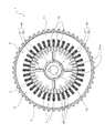
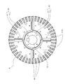
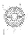
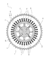
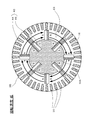
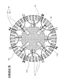
- FIG. 2 is a cross-sectional view perpendicular to the axis as seen in the section taken along the line II-II in FIG. It is the figure which expanded the rotor in FIG. It is a figure which shows an example of the magnetic flux path
- FIG. 5 is a radial cross-sectional view illustrating an example of a configuration of a relative angle restriction mechanism during low-speed operation as viewed in a cross-section taken along line VI-VI in FIG. 1.
- It is radial direction sectional drawing showing an example of a structure of the relative angle control mechanism at the time of high speed driving
- It is a figure showing an example of the change of the drive torque with respect to the rotational speed at the time of operating a rotary electric machine.
- FIG. 1 shows an example of an axial cross section of the rotating electrical machine of the present embodiment
- FIG. 2 shows an example of an axial orthogonal cross section of the rotating electrical machine as seen in the section taken along the line II-II in FIG. 3 shows only the rotor in FIG. 2 in an enlarged manner.
- the rotating electrical machine 1 of the present embodiment includes a substantially cylindrical stator 2 and a rotor 3 having a shaft 10.
- the rotating electrical machine 1 is a so-called inner rotor type motor in which a rotor 3 is disposed inside a stator 2.
- the rotating electrical machine 1 may be used as a generator.
- the rotating electrical machine 1 is a SIM (Synchronous Induction Motor) having a secondary conductor 30 and a permanent magnet 40 on the rotor core 20 of the rotor 3 and having both an induction type and a synchronous type configuration.
- the rotating electrical machine 1 of the present embodiment also includes a variable field type configuration that changes the field magnetic flux.
- the stator 2 is fixed to the inner periphery of a substantially cylindrical frame 4.
- a load side bracket 11 is provided on the load side (right side in FIG. 1) of the frame 4.
- An anti-load side bracket 13 is provided on the anti-load side of the frame 4 (left side in FIG. 1).
- the load side bracket 11 and the anti-load side bracket 13 are fixed to the frame 4 with bolts (not shown).
- the stator 2 has a stator core 5 and a stator winding 7.
- the “load side” refers to the direction in which a load is attached to the rotating electrical machine 1, that is, the direction in which the shaft 10 protrudes (right side in FIG. 1) in this example. It points in the opposite direction to the load side (left side in FIG. 1).
- the stator core 5 includes a substantially cylindrical yoke portion 71 fixed to the inner periphery of the frame 4 and a plurality (36 in the illustrated example) of teeth portions 72 protruding from the yoke portion 71 toward the inner periphery. .
- the stator winding 7 (an example of a winding) is mounted in a slot between two teeth portions 72 adjacent in the circumferential direction.
- a rotating magnetic field in which a magnetic pole rotates around the axis AX is generated in the stator core 5.
- the rotor 3 is disposed inside the stator 2 so as to face the inner peripheral surface of the stator 2 in the radial direction via a magnetic gap.
- the rotor 3 includes a substantially cylindrical first rotor core 21 and a second rotor disposed coaxially and relative to the first rotor core 21 on the radially inner side of the first rotor core 21.
- An iron core 22 and a shaft 10 fixed so as to be coaxial with the second rotor iron core 22 in the radial direction are provided.
- the shaft 10 is rotatably supported around the axis AX by bearings 14 respectively installed on the load side bracket 11 and the anti-load side bracket 13.
- the rotor 3 includes a plurality of secondary conductors 30 (44 in the illustrated example) and a plurality (eight in the illustrated example) of permanent magnets 40.
- the rotor 3 includes a relative angle restriction mechanism 50. The configuration and function of the relative angle restriction mechanism 50 will be described in detail later.
- the above “coaxial” is not a strict meaning, and tolerances, errors, etc. in design and manufacturing are allowed. That is, it means “substantially coaxial”.
- the “axial direction” is the direction of the axis AX
- the “radial direction” is a radial direction centered on the axis AX
- the “circumferential direction” is a circumference centered on the axis AX.
- Direction in other words, the rotational direction of the shaft 10.
- the rotor core 20 is formed so that the axial length is substantially equal to the stator core 5.
- the first rotor core 21 is rotatable about the axis AX with respect to the stator 2 and is axially centered with respect to the shaft 10, the second rotor core 22, and a plurality of second permanent magnets 42 described later. Relative rotation about AX is possible.
- the rotation speed range and the rotation angle range in which relative rotation of the first rotor core 21 with respect to the second rotor core 22 is allowed are restricted by the function of the relative angle restriction mechanism 50 described later.
- first permanent magnets 41 arranged inside the first rotor core 21, and along with the rotation of the first rotor core 21.
- the rotor 3 has a configuration as a rotor used for a so-called IPM (Internal Permanent Magnet) type synchronous motor in which a plurality of first permanent magnets 41 are embedded in the first rotor core 21.
- IPM Internal Permanent Magnet
- the four first permanent magnets 41 are specifically configured so that the same magnetic poles (N poles or S poles) of the first permanent magnets 41 adjacent in the rotation direction face each other in the rotation direction. Arranged radially inside the first rotor core 21 about the axis AX.
- each of the four regions partitioned in the rotation direction by the four first permanent magnets 41 constitutes the magnetic pole portion 21 a.
- the second rotor core 22 rotates together with the shaft 10.
- the same number as the plurality of magnetic pole portions 21a formed in the first rotor core 21, that is, in this example Four second permanent magnets 42 are provided. These second permanent magnets 42 are installed at equal intervals so that the polarities in the radial direction are alternately different along the rotation direction (N pole ⁇ S pole ⁇ N pole ⁇ S pole ⁇ ). ing.
- the plurality of secondary conductors 30 are rod-shaped members each made of a nonmagnetic and conductive material (for example, aluminum), and are radially outer than the first permanent magnet 41 inside the first rotor core 21. Are arranged at equal intervals in the circumferential direction on the side.
- each secondary conductor 30 is formed in a substantially pentagon shape that is long in the radial direction when viewed in an axial orthogonal cross section, and the end portions on the load side and the anti-load side are annular side plates 51 and 52 (rear Are connected via a detailed description). Specifically, end portions on the load side (right side in FIG. 1) of the secondary conductors 30 are connected to each other via the first load side plate 51, and are electrically connected to each other.
- the end portions on the anti-load side (left side in FIG. 1) of the secondary conductors 30 are connected via the first anti-load side plate 52, and are electrically connected to each other. That is, the rotor 3 has a configuration as a rotor used for a so-called cage-type induction motor having a cage-shaped secondary conductor 30 as a whole.
- a driving torque (hereinafter referred to as magnet torque) is obtained between the rotating magnetic field of the stator 2 and the field magnetic flux from the permanent magnet 40 provided on the rotor 3.
- magnet torque a driving torque
- high driving torque and high efficiency can be obtained at the time of stable operation.
- the stator 3 is rotated by rotating the rotor 3 at a certain or higher inertia speed by a separate means. It is necessary to obtain synchronization with the two rotating magnetic fields.
- the rotor core 20 includes a secondary conductor 30 and a permanent magnet 40, that is, both inductive and synchronous configurations. Since the rotor 3 includes the secondary conductor 30, this SIM can be started automatically from a stop by simply supplying commercial AC power directly as in the induction type. In addition, since the rotor 3 includes a permanent magnet, the SIM can be synchronously driven in synchronization with the rotating magnetic field when the rotor 3 is rotated at a certain inertia speed or more.
- the magnetic flux of the permanent magnet 40 affects the induction current in the secondary conductor 30 and the generation of the magnetic flux, the startup torque (induction torque) as an induction type is reduced and noise and vibration are generated during startup acceleration. There is a case.
- the magnetization intensity of the permanent magnet 40 is weakened to avoid this problem, the driving torque (magnet torque) at the time of synchronous driving is reduced.
- the magnetic flux of the induced current in the secondary conductor 30 and the magnetic flux of the permanent magnet 40 affect each other, there is a problem that it is difficult to achieve both the induction type and synchronous type advantages in the SIM.
- the SIM-structured rotor 3 interlinks with the stator winding 7 of the stator 2 by a plurality of permanent magnets 40 (in other words, out of the magnetic flux generated from the permanent magnets 40).
- the magnetic flux emitted to the outer peripheral side of the rotor 3 is changed.
- the drive torque (magnet torque) by the magnetic flux of the permanent magnet 40 at the time of synchronous operation is increased. Is possible. Details thereof will be sequentially described below.
- FIG. 4 shows a state where the load torque is small.
- the first rotor core 21 is magnetically attracted to the second rotor core 22 at an angular position where the magnetic pole portion 21a and the second permanent magnet 42 having different polarities face each other in the radial direction. Is held by.
- most of the magnetic flux of the magnetic pole portion 21 a (first permanent magnet 41) is short-circuited to the second permanent magnet 42 located radially inward from the magnetic pole portion 21 a (first permanent magnet 41). That is, the field magnetic flux interlinking with the stator winding 7 of the stator 2 is minimized. For this reason, even if a rotating magnetic field is generated in the stator 2, almost no magnet torque is generated in the rotor 3.
- the first rotor core 21 and the second rotor core 22 are arranged at the relative angles shown in FIG. 4, that is, the magnetic pole portions 21a and the second permanent magnets 42 having different polarities from each other.
- the state of the field magnetic flux in a state where is directly opposed in the radial direction is called the “minimum” field magnetic flux.
- FIG. 5 shows a state where the load torque is increasing.
- the relative angle between the first rotor core 21 and the second rotor core 22 increases against the magnetic attractive force (in the example shown in FIG. 5, approximately 45 ° in the clockwise direction). ).
- the portion where the polarities of the magnetic pole portion 21a and the second permanent magnet 42 match increases, and the magnetic flux that is short-circuited from the first permanent magnet 41 to the second permanent magnet 42 decreases.
- the polarity of the magnetic pole part 21a comes to be strengthened by the 2nd permanent magnet 42, the field magnetic flux for the amount discharge
- FIG. 6 shows a state where the load torque is further increased.
- the first rotor iron core 21 and the second rotor iron core 22 further increase the relative angle against the magnetic attraction force, and the angular position where the polarities of the magnetic pole part 21a and the second permanent magnet 42 coincide with each other. It has become.
- the magnetic flux that is short-circuited from the magnetic pole portion 21a to the second permanent magnet 42 is almost eliminated, and the magnetic flux of the magnetic pole portion 21a is further strengthened by the second permanent magnet 42. Maximum. For this reason, when a rotating magnetic field is generated in the stator 2, magnet torque is most effectively generated.
- the first rotor core 21 and the second rotor core 22 are arranged at the relative angles shown in FIG. 6, that is, the polarities of the magnetic pole portion 21a and the second permanent magnet 42 are the same.
- the rotating electrical machine 1 sets the above-described fluctuation range of the relative angle between the first rotor core 21 and the second rotor core 22 to the magnetic pole pitch of the second permanent magnet 42 as shown in FIGS.
- a relative angle regulating mechanism 50 that regulates an angle range of approximately 90 ° or less is provided.
- the relative angle regulating mechanism 50 also has a function of switching between induction torque and magnet torque according to the rotational speed of the rotor 3.
- FIG. 7 shows an example of a cross section perpendicular to the axis of the relative angle regulating mechanism 50 as seen in the cross section taken along the arrow VII-VII in FIG.
- an annular first load side plate 51 and a first antiload side plate 52 are respectively connected to the load side end portion and the counter load side end portion of the first rotor core 21. It is mounted so as to be coaxial with 10.
- the first load side plate 51 (an example of the first plate) and the first anti-load side plate 52 are fixed to the first rotor core 21 by penetration of bolts 55.
- annular second load side plate 53 (an example of a second plate) and a second anti load side plate 54 (an example of the second plate) are respectively provided at the load side end portion and the counter load side end portion of the second rotor core 22.
- An example of the second plate is mounted so as to be coaxial with the shaft 10.
- the second load side plate 53 and the second anti-load side plate 54 are supported in the axial direction in contact with the inner ring of the bearing 14 supported by the load-side bracket 11 and the anti-load-side bracket 13, respectively.
- the key 15 is fixed so as not to rotate relative to the shaft 10.
- the first load side plate 51 and the first anti-load side plate 52 rotate with the rotation of the first rotor core 21, and the shaft 10, the second rotor core 22, the second load side plate 53, and The second counter-load side plate 54 can be rotated around the axis AX.
- the inner peripheral surface of the first load side plate 51 and the outer peripheral surface of the second load side plate 53 facing each other in the radial direction are separated by a predetermined distance D.
- a plurality (four in this example) of first protrusions 56 protruding inward in the radial direction are provided at equal intervals in the rotation direction.
- the inner peripheral end of each first protrusion 56 is opposed to the outer peripheral surface of the second load side plate 53 in the radial direction through a narrow gap.
- a plurality (four in this example) of second protrusions 57 protruding outward in the radial direction are provided on the outer peripheral surface of the second load side plate 53 at equal intervals in the rotational direction.
- the outer peripheral end of each second protrusion 57 is in contact with the inner peripheral surface of the first load side plate 51 so as to be relatively rotatable.
- first protrusions 56 and second protrusions 57 are provided in the rotation direction at the same angular interval (approximately 90 ° interval), and are in an arrangement relationship overlapping each other in the radial direction. That is, the first protrusions 56 and the second protrusions 57 are alternately arranged in the rotation direction at the same radial position. For this reason, each 1st projection part 56 can contact in the circumferential direction with the two 2nd projection parts 57 located in each rotation direction both sides, and with respect to the 2nd load side plate 53 in the angle range which carries out relative rotation between them.
- the fluctuation range of the relative angle of the first load side plate 51 is restricted. That is, the first load side plate 51 and the second load side plate 53 constitute a relative angle restricting mechanism 50 and restrict the fluctuation range of the relative angle between the first rotor core 21 and the second rotor core 22.
- the variation range of the relative angle between the first rotor core 21 and the second rotor core 22 is such that the number of the first protrusions 56 and the second protrusions 57, the arrangement angle interval, and the thicknesses in the respective rotation directions. It can be adjusted by setting the dimensions. By adjusting the fluctuation range of the relative angle to be equal to or less than the magnetic pole pitch of the magnetic pole portion 21a and the second permanent magnet 42 and adjusting the phase in the rotation direction, the field magnetic flux and the magnet torque shown in FIGS. Change is possible.
- the movable weir portion 58 is provided inside each first protrusion 56.
- the movable dam portion 58 is entirely composed of a permanent magnet (an example of a third permanent magnet), and is provided so as to be movable in the radial direction inside the first protrusion 56.
- the movable weir 58 protrudes from the inner peripheral tip of the first protrusion 56 by its own magnetic attractive force and contacts the outer peripheral surface of the second load side plate 53. .
- the movable weir portion 58 is drawn into the first protrusion 56 by its own centrifugal force and is separated from the outer peripheral surface of the second load side plate 53.
- the first load side plate 51 is closed between the inner peripheral surface of the first load side plate 51 and the outer peripheral surface of the second load side plate 53 between the two second protrusions 57 adjacent in the rotation direction.
- a chamber 59 of space is formed.
- the chamber 59 is sandwiched between the first load side plate 51 and the second load side plate 53 and is also closed in the axial direction.
- four chambers 59 are provided, and each first protrusion 56 can move in the rotation direction in each chamber 59.
- Each chamber 59 is filled with an incompressible fluid having lubricity, such as grease 60, and the inner peripheral side of the first protrusion 56 when each first protrusion 56 moves in the chamber 59.
- a gap between the tip and the outer peripheral surface of the second load side plate 53 serves as an orifice, and the grease 60 circulates between spaces on both sides in the rotational direction of the first protrusion 56.
- incompressible fluid means that the volume of the fluid does not change even when a force is applied from the outside and the density is substantially constant, and the influence of compression and expansion can be substantially ignored. It refers to fluid.
- the chamber 59 is partitioned in the circumferential direction and the flow of the grease 60 is blocked.
- the first protrusion 56 cannot move in the rotation direction. That is, when the rotor 3 rotates at a low speed lower than a predetermined rotation speed, the first rotor core 21 is held without being able to rotate relative to the second rotor core 22.
- the phase in the rotational direction of the relative angle restricting mechanism 50 is set so that the relative relationship between the relative angles of 51 and the second load side plate 53 is compatible.
- the relative angle regulating mechanism 50 allows the first load side plate 51 to rotate in the clockwise direction with respect to the second load side plate 53 as shown in FIG. To do.
- the relative angle regulating mechanism 50 allows the first rotor core 21 to rotate in the clockwise direction with respect to the second rotor core 22 in the order of FIG. 4 ⁇ FIG. 5 ⁇ FIG.
- FIG. 9 shows an example of a change in drive torque with respect to the rotation speed (rotation speed) when the rotating electrical machine 1 of the present embodiment is operated. The operation process of the rotating electrical machine 1 will be described with reference to FIG.
- the relative angle restriction mechanism 50 causes the first rotor core 21 to move relative to the second rotor core 22 as described above with respect to the relative angle shown in FIG.
- the field magnetic flux is fixed to the outer peripheral side of the rotor 3 from the magnetic pole portion 21a and the second permanent magnet 42 and is minimized. For this reason, even if a rotating magnetic field is generated in the stator 2, almost no magnet torque is generated in the rotor 3, and inductive torque is most effectively generated instead. That is, when the motor is stopped, the rotating electrical machine 1 functions almost as an induction motor, and a large starting torque can be obtained only by the induction torque by directly supplying commercial AC power with a fixed frequency. When this starting torque is sufficiently larger than a load torque (not shown), smooth self-starting is possible.
- the state in which the field magnetic flux is “minimum” means that the first rotor core 21 and the second rotor core 22 are arranged at the relative angles shown in FIG. 4, that is, the magnetic pole portions 21a having different polarities. And the state of the field magnetic flux in a state where the second permanent magnet 42 faces the radial direction.
- the rotating electrical machine 1 increases the rotational speed while maintaining the function as the induction motor, and provides the largest stalling torque at the specific rotational speed (for example, about 1200 min ⁇ 1 in the example shown in FIG. 9).
- the speed is increased to a synchronous speed at which the induction torque becomes 0 (for example, about 1800 min ⁇ 1 in the example shown in FIG. 9).
- the magnetic flux of the permanent magnet 40 has little influence on the induction operation, so that smooth acceleration with reduced noise and vibration is possible.
- the rotational speed is stabilized by the balance between the induction torque and the load torque in the stable speed region from the stationary torque rotational speed to the synchronous speed rotational speed.
- the rotation speed (in the example shown in FIG. 9) that switches between fixing and allowing the relative rotation between the first rotor core 21 and the second rotor core 22 within this stable speed region. For example, about 1720 min ⁇ 1 ) is set.
- the movable weir portion 58 is separated from the outer peripheral surface of the second load side plate 53 and the chamber 59 The grease 60 is allowed to flow, and relative rotation between the first rotor core 21 and the second rotor core 22 is allowed.
- the rotor 3 rotates at a sufficient inertial speed near the synchronous speed, the induced torque is sufficiently low, and the magnet torque increases due to the load torque through the steps of FIGS.
- the shift to the synchronous operation by the magnet torque is smoothly performed.
- slippage between the rotating magnetic field of the stator 2 and the rotor 3 is eliminated, so that almost no induction torque is generated. Instead, the magnet torque is most effectively generated and the high driving torque is obtained. It can be driven with high efficiency.
- the 2nd rotor core 22 provided with the magnet 42 is equivalent to an example of the means to change the field magnetic flux linked to the winding by a plurality of permanent magnets.
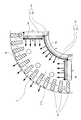
- FIG. 10 shows an enlarged view of one magnetic pole portion 21a and its periphery in the rotor 3.
- a plurality of secondary conductors 30 are arranged at equal intervals in the rotational direction outside the first permanent magnet 41 in the radial direction.
- the secondary conductor 30 closest to each first permanent magnet 41 among these is arranged so that the first permanent magnet 41 and the circumferential center substantially coincide.
- the non-magnetic secondary conductor 30 arranged so as to overlap the first permanent magnet 41 in the circumferential direction is a so-called flux that prevents short-circuiting of the magnetic flux between the magnetic pole portions 21 a at the outer peripheral side end of the first permanent magnet 41.
- the first permanent magnet 41 and the secondary conductor 30 are not completely brought into contact with each other in the radial direction in order to secure a flow path of magnetic flux due to the induced current around the secondary conductor 30 during the induction operation. It arrange
- the maximum total amount of magnetic flux that can be generated in one magnetic pole portion 21a is the radial dimension Mr of each of the two first permanent magnets 41 surrounding the magnetic pole portion 21a, and the circumferential dimension Mc of one second permanent magnet 42. Is proportional to the total dimension (2Mr + Mc). Further, when there are N circumferential gaps between the secondary conductors 30 corresponding to one magnetic pole portion 21a (11 places in this example), the total dimension (N ⁇ W) of the separation distance W of the circumferential gaps. ) Is the passing width dimension of the field magnetic flux.
- the field magnetic flux interlinked with the stator winding 7 of the stator 2 by the plurality of permanent magnets 40 in the rotor 3 having both inductive and synchronous configurations. Is configured to change.
- the influence of the magnetic flux of the permanent magnet 40 on the generation of the induction torque at the start-up is suppressed, and the drive torque of the magnet torque at the time of synchronous operation can be increased.
- the rotor 3 does not slip with respect to the rotating magnetic field, so that the influence of the induction torque on the magnet torque is reduced.
- noise vibration can be suppressed and the starting torque and the driving torque during synchronous operation can be increased, so that both the advantages of the induction type and the synchronous type can be achieved.
- the rotor 3 is particularly configured to change the arrangement of the plurality of permanent magnets 40 (relative arrangement of the first permanent magnet 41 and the second permanent magnet 42) according to the rotational speed. Yes. This makes it possible to change the field magnetic flux in the rotor 3 with a relatively simple mechanical structure regardless of electrical control.
- the rotor 3 minimizes the field magnetic flux at the time of stop, and the field at the time of high speed rotation higher than a predetermined rotation speed (1720 min ⁇ 1 in the example shown in FIG. 9) is higher than that at the time of stop. It is configured to increase the magnetic flux.
- a predetermined rotation speed 1720 min ⁇ 1 in the example shown in FIG. 9
- the magnet torque can be increased more than when the rotor 3 is stopped, and the driving torque during the synchronous operation can be increased.
- the synchronous operation can be started in synchronization with the rotating magnetic field of the stator 2 regardless of the magnitude of the load torque.
- this synchronous operation no slip occurs between the rotating magnetic field of the stator 2 and the rotor 3, so that almost no induction torque is generated and the rotor 3 is driven only by the magnet torque.
- the same magnetic pole as the first rotor core 21 and the second rotor core 22 disposed on the radial inner side of the first rotor core 21 and rotatable relative to the first rotor core 21 are configured in the first rotor core 21 by a plurality of first permanent magnets 41 radially disposed inside the first rotor core 21 so as to face each other in the circumferential direction. And at least one second permanent magnet 42 disposed on the outer periphery of the second rotor core 22 so that the magnetic poles are alternately different along the circumferential direction.
- the plurality of secondary conductors 30 are made of a non-magnetic material and include the secondary conductors 30 arranged at positions overlapping the first permanent magnet 41 in the circumferential direction.
- the non-magnetic secondary conductor 30 that overlaps the first permanent magnet 41 in the circumferential direction serves as a so-called flux barrier that prevents short-circuiting of the magnetic flux between the magnetic pole portions 21 a at the outer peripheral side end of the first permanent magnet 41. Function.
- the plurality of secondary conductors 30 are arranged at equal intervals in the circumferential direction in the first rotor core 21, and the circumference between the plurality of secondary conductors 30 corresponding to one magnetic pole portion 21a.
- the sum of the distances in the direction (N ⁇ W) is the sum of the radial dimension Mr of each of the two first permanent magnets 41 surrounding one magnetic pole portion 21a and the circumferential dimension Mc of one second permanent magnet 42 (2Mr + Mc). ) Is set to be larger than half.
- the rotor 3 regulates the fluctuation range of the relative angle between the first rotor core 21 and the second rotor core 22 to an angle range equal to or smaller than the magnetic pole pitch of the second permanent magnet 42.
- a relative angle regulating mechanism 50 is provided.
- the relative angle regulating mechanism 50 has a first load side plate 51 fixed to at least one end portion in the axial direction of the first rotor core 21, and the first load side plate 51 has a diameter. At least one first projection 56 projecting inward in the direction, a second load side plate 53 fixed to at least one end in the axial direction of the second rotor core 22, and a second load side plate 53 And at least one second protrusion 57 that protrudes outward in the radial direction and can contact the first protrusion 56 in the circumferential direction.
- the relative angle regulating mechanism 50 can regulate the fluctuation range of the relative angle between the first rotor core 21 and the second rotor core 22 with a relatively simple mechanical structure.
- the relative angle regulating mechanism 50 is formed between the inner peripheral surface of the first load side plate 51 and the outer peripheral surface of the second load side plate 53, and contains an incompressible fluid therein. It has a filled chamber 59 and a movable weir 58 that can partition the chamber 59 in the circumferential direction by moving in the radial direction inside the first protrusion 56. As a result, when the movable dam portion 58 partitions the chamber 59 in the circumferential direction, the relative angle regulating mechanism 50 is not connected to the first rotor core 21 and the second rotor core 22 regardless of the load torque of the rotor 3. Hold the relative angle so as not to fluctuate.
- the relative angle regulating mechanism 50 performs the second rotation with the first rotor core 21 by the load torque of the rotor 3. Variation in relative angle with the core iron core 22 is allowed.
- a narrow gap between the inner peripheral tip of the first protrusion 56 and the outer peripheral surface of the second load side plate 53 serves as an orifice between the spaces on both sides in the rotational direction of the first protrusion 56. The grease 60 is circulated between them.
- the entire chamber functions as a damper and an impact caused by the fluctuation of the load torque. Can be absorbed.
- the movable dam portion 58 is formed of a permanent magnet, and the rotor 3 comes into contact with the outer peripheral surface of the second load side plate 53 when the rotor 3 rotates at a low speed lower than a predetermined rotation speed. Compart in the circumferential direction. Further, when the rotor 3 rotates at a higher speed than the predetermined rotation speed, the chamber 59 is communicated in the circumferential direction while being separated from the outer peripheral surface of the second load side plate 53.
- the relative angle regulating mechanism 50 holds the relative angle between the first rotor core 21 and the second rotor core 22 so as not to fluctuate regardless of the load torque of the rotor 3. That is, when the rotor 3 is rotating at a low speed including when it is stopped, the maximum induction torque as the starting torque can be ensured regardless of the load torque.
- the relative angle restriction mechanism 50 allows the relative angle between the first rotor core 21 and the second rotor core 22 to vary due to the load torque of the rotor 3. That is, when the rotor 3 is rotating at a high speed and the load torque is high, the magnet torque is increased compared with the low load torque, and the driving torque during the synchronous operation is increased.
- the rotating electrical machine 1 includes 36 slots in which the stator winding 7 is accommodated on the stator 2 side, four magnetic pole portions 21a on the rotor 3 side, and the secondary conductor 30. 44 were provided. That is, when viewed as an induction type, it has a 44P36S slot combination configuration, and when viewed as a synchronous type, it has a 4P36S slot combination configuration.
- FIG. 11 An example of other slot combinations is shown in FIG.
- the number of the secondary conductors 30 is 28, which is a combination slot configuration of 28P36S when viewed in the inductive type (4P36S remains in the synchronous type).
- What is common to these slot combination configurations is that the number of secondary conductors 30 is different from the number of slots.
- the freedom degree of design of the rotary electric machine 1 can be improved.
- the distance between the secondary conductors 30 in the circumferential direction can be increased by making the number of the secondary conductors 30 smaller than the number of slots, so that the field magnetic flux is increased.
- the magnetic flux can be easily prevented from being short-circuited between the magnetic poles in the first rotor core 21.
- Second Embodiment> Next, a second embodiment will be described. In the second embodiment, parts different from the first embodiment will be mainly described. In addition, components having substantially the same functions as those in the first embodiment are denoted by the same reference numerals in principle, and redundant description of these components is omitted as appropriate.
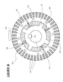
- FIG. 12 shows an example of an axial orthogonal cross section of the rotating electrical machine 1A of the present embodiment corresponding to FIG. 2, and FIG. 13 shows only the rotor 3B in FIG.
- the configuration of the stator 2 is the same as that of the first embodiment, and the configuration of the rotor 3B is different from that of the first embodiment.
- the rotor 3 ⁇ / b> B according to the present embodiment includes a substantially cylindrical rotor core 23, a shaft 10 ⁇ / b> A fixed to be coaxial with the center of the rotor core 23, and a plurality of secondary conductors 30. (44 in the illustrated example) and a plurality (eight in the illustrated example) of permanent magnets 40 are provided.
- the rotor 3B includes the relative angle regulating mechanism 50 corresponding to the number of poles, as in the first embodiment.
- the shaft 10A is a non-magnetic shaft body formed with a larger outer diameter than the shaft 10 of the first embodiment, and the rotor core 23 rotates together with the shaft 10A.
- Four of the plurality of permanent magnets 40 included in the rotor 3 ⁇ / b> B are fourth permanent magnets 44 that are radially fixedly arranged inside the rotor core 23.
- the other four permanent magnets 40 are fifth permanent magnets 45 that are arranged radially between the fourth permanent magnets 44 in the circumferential direction and are arranged to be movable radially inward of the fourth permanent magnets 44. is there.
- the fourth permanent magnet 44 and the fifth permanent magnet 45 have substantially the same radial length, and the fourth permanent magnet 44 and the fifth permanent magnet 45 adjacent in the circumferential direction have the same magnetic pole. Are arranged so as to face each other in the circumferential direction.
- the fifth permanent magnet 45 is movable from an inner peripheral side position where almost the entire part enters the shaft 10A to the same radial position as the fourth permanent magnet 44, and each of the fifth permanent magnets 45 has a diameter by a coil spring 16 (an example of an elastic member). It is pressed toward the inside in the direction.
- FIG. 14 shows a state where the rotation speed is low including when the vehicle is stopped.
- the fifth permanent magnet 45 is held at a position radially inward of the fourth permanent magnet 44 (inside the shaft 10 ⁇ / b> A) by the repulsive force between the fourth permanent magnet 44 and the pressing force of the coil spring 16.
- the in this state the magnetic flux of the fifth permanent magnet 45 circulates inside the non-magnetic shaft 10A, and most of the magnetic flux of the fourth permanent magnet 44 is adjacent to each other via a path along the circumferential direction. The amount of field magnetic flux generated from these permanent magnets 40 is minimized.
- the induction torque as the starting torque is maximized.
- the state where the field magnetic flux is “minimum” means that the fourth permanent magnet 44 and the fifth permanent magnet 45 are in the arrangement shown in FIG. 14, that is, the fifth permanent magnet 45 moves radially inward. That is, the state of the field magnetic flux in a state where it is not substantially located between the fourth permanent magnets adjacent in the circumferential direction.
- a region between the fourth permanent magnet 44 and the fifth permanent magnet 45 adjacent in the circumferential direction is configured as the magnetic pole portion 23a, and the field magnetic flux emitted from each magnetic pole portion 23a to the outer peripheral side of the rotor 3B increases. .
- the magnet torque is increased more than when the rotor 3B is stopped, and the driving torque during the synchronous operation is increased.
- the predetermined speed at which the fifth permanent magnet 45 starts to move to the outer peripheral side is the elastic coefficient of the coil spring 16, the mass of the fifth permanent magnet 45 itself (centrifugal force), and the magnetization strength of the fourth and fifth permanent magnets 44, 45. (Repulsive force) can be adjusted. Then, by setting this predetermined speed within the stable speed region of the guidance operation shown in FIG. 9, it is possible to smoothly switch between the guidance operation and the synchronous operation as in the first embodiment.
- the rotary electric machine 1A is arranged radially between the plurality of fourth permanent magnets 44 fixedly arranged radially on the rotor core 23 and the plurality of fourth permanent magnets 44 in the circumferential direction.
- a plurality of fifth permanent magnets 45 arranged to be movable radially inward from the fourth permanent magnets 44.
- the fourth permanent magnet 44 and the fifth permanent magnet 45 are arranged so that the same magnetic poles face each other in the circumferential direction.
- the plurality of fifth permanent magnets 45 are more radial than the plurality of fourth permanent magnets 44 when the rotor 3B rotates at a low speed lower than a predetermined rotation speed (for example, 1720 min ⁇ 1 in FIG. 9).
- a predetermined rotation speed for example, 1720 min ⁇ 1 in FIG. 9.
- the plurality of fifth permanent magnets 45 are located at positions overlapping with the plurality of fourth permanent magnets 44 in the radial direction. Thereby, the passage of magnetic flux and the type of torque can be changed based on the predetermined rotation speed, and the synchronous operation can be started smoothly.
- the rotor 3B includes a plurality of coil springs 16 that press the plurality of fifth permanent magnets 45 radially inward.
- the radial position of the fifth permanent magnet 45 can be adjusted according to the rotational speed by adjusting the elastic coefficient of the coil spring 16.
- the magnet torque can be adjusted according to the rotational speed, and the predetermined rotational speed for switching between the induction torque and the magnet torque can also be adjusted when the rotating electrical machine 1A is manufactured.
- the predetermined rotation speed can be adjusted by the mass (centrifugal force) of the fifth permanent magnet 45 and the magnetization strength (repulsive force) of the fourth and fifth permanent magnets 44 and 45 at the design stage. It is.
Landscapes
- Engineering & Computer Science (AREA)
- Power Engineering (AREA)
- Permanent Magnet Type Synchronous Machine (AREA)
- Permanent Field Magnets Of Synchronous Machinery (AREA)
Abstract
【課題】起動トルク及び同期運転時の駆動トルクを増大する。 【解決手段】固定子巻線7を備えた固定子2と回転子3とを有する回転電機1であって、回転子3は、回転子鉄心20と、回転子鉄心20に配置された複数の永久磁石40と、回転子鉄心20の複数の永久磁石40よりも径方向外側に配置され、固定子2の回転磁界とのすべりにより誘導電流が流れる複数の二次導体30と、を有し、複数の永久磁石40による固定子巻線7に鎖交する界磁磁束が変化するように構成される。
Description
開示の実施形態は、回転電機に関する。
特許文献1には、回転子鉄心に2次導体と永久磁石を備えた電動機が記載されている。
上記従来技術のように誘導型と同期型の両方の構成を備えた回転電機においては、二次導体での誘導電流の磁束と永久磁石の磁束が相互に影響し合うことにより、起動トルク及び同期運転時の駆動トルクが不足するという課題があった。
本発明はこのような問題点に鑑みてなされたものであり、起動トルク及び同期運転時の駆動トルクを増大することが可能な回転電機を提供することを目的とする。
上記課題を解決するため、本発明の一の観点によれば、巻線を備えた固定子と回転子とを有する回転電機であって、前記回転子は、回転子鉄心と、前記回転子鉄心に配置された複数の永久磁石と、前記回転子鉄心の前記複数の永久磁石よりも径方向外側に配置され、前記固定子の回転磁界とのすべりにより誘導電流が流れる複数の二次導体と、を有し、前記複数の永久磁石による前記巻線に鎖交する界磁磁束が変化するように構成される回転電機が適用される。
また、本発明の別の観点によれば、巻線を備えた固定子と回転子とを有する回転電機であって、前記回転子は、回転子鉄心と、前記回転子鉄心に配置された複数の永久磁石と、前記回転子鉄心の前記複数の永久磁石よりも径方向外側に配置され、前記固定子の回転磁界とのすべりにより誘導電流が流れる複数の二次導体と、前記複数の永久磁石による前記巻線に鎖交する界磁磁束を変化させる手段と、を有する回転電機が適用される。
本発明によれば、騒音振動の抑制と、起動トルク及び同期運転時の駆動トルクの増大が可能となる。
以下、実施形態について図面を参照しつつ説明する。
<1.第1実施形態>
まず、第1実施形態について説明する。
まず、第1実施形態について説明する。
(1-1.回転電機における固定子と回転子の構成)
まず、図1~図3を参照しつつ、本実施形態に係る回転電機の固定子と回転子の構成の一例について説明する。図1は本実施形態の回転電機の軸方向断面の一例を示しており、図2は図1中の矢視II-II断面で見た回転電機の軸直交断面の一例を示しており、図3は図2中の回転子だけを拡大して示している。
まず、図1~図3を参照しつつ、本実施形態に係る回転電機の固定子と回転子の構成の一例について説明する。図1は本実施形態の回転電機の軸方向断面の一例を示しており、図2は図1中の矢視II-II断面で見た回転電機の軸直交断面の一例を示しており、図3は図2中の回転子だけを拡大して示している。
これら図1~図3に示すように、本実施形態の回転電機1は、略円筒状の固定子2と、シャフト10を備えた回転子3とを有する。
回転電機1は、固定子2の内部に回転子3が配置された、いわゆるインナーロータ型のモータである。なお、回転電機1は発電機として使用されてもよい。回転電機1は、回転子3の回転子鉄心20に二次導体30と永久磁石40を備えており、誘導型と同期型の両方の構成を備えたSIM(Synchronous Induction Motor)である。さらに、本実施形態の回転電機1は、界磁磁束を変化させる可変界磁型の構成も備えている。
固定子2は、略円筒状のフレーム4の内周に固定されている。フレーム4の負荷側(図1中右側)には、負荷側ブラケット11が設けられている。フレーム4の反負荷側(図1中左側)には、反負荷側ブラケット13が設けられている。これら負荷側ブラケット11と反負荷側ブラケット13は、図示しないボルトによりフレーム4に固定されている。また、固定子2は、固定子鉄心5と固定子巻線7とを有する。
なお、本明細書において「負荷側」とは回転電機1に対して負荷が取り付けられる方向、すなわちこの例ではシャフト10が突出する方向(図1中右側)を指し、「反負荷側」とは負荷側の反対方向(図1中左側)を指す。
固定子鉄心5は、フレーム4の内周に固定された略円筒形状のヨーク部71と、ヨーク部71から内周側に突出した複数(図示の例では36個)のティース部72とを備える。
固定子巻線7(巻線の一例)は、周方向に隣り合う2つのティース部72の間のスロットに装着されている。この固定子巻線7に対して例えば3相交流電力を外部から給電することで、固定子鉄心5には軸心AX周りに磁極が回転する回転磁界が発生する。
回転子3は、固定子2の内周面と径方向に磁気的空隙を介して対向するように、固定子2の内部に配置されている。この回転子3は、略円筒状の第1回転子鉄心21と、第1回転子鉄心21の径方向内側に第1回転子鉄心21に対し同軸で相対回転可能に配置された第2回転子鉄心22と、第2回転子鉄心22の径方向内側に同軸となるよう固定されたシャフト10とを備えている。シャフト10は、負荷側ブラケット11及び反負荷側ブラケット13にそれぞれ設置された軸受14により軸心AX周りに回転自在に支持されている。また回転子3は、複数の二次導体30(図示の例では44個)と、複数(図示の例では8個)の永久磁石40とを備える。他にも、回転子3は相対角度規制機構50を備えているが、この相対角度規制機構50の構成と機能については後に詳述する。
なお、上記「同軸」は厳密な意味ではなく、設計上、製造上の公差、誤差等が許容される。すなわち、「実質的に同軸」という意味である。また、本明細書において「軸方向」は上記軸心AXの方向であり、「径方向」は軸心AXを中心とする半径方向であり、「周方向」は軸心AXを中心とする周方向、言い換えるとシャフト10の回転方向である。
回転子鉄心20は、軸方向長さが固定子鉄心5とほぼ等しくなるように形成されている。また、第1回転子鉄心21は、固定子2に対し軸心AX周りに回転可能であると共に、シャフト10、第2回転子鉄心22、及び後述の複数の第2永久磁石42に対し軸心AX周りに相対回転可能である。ただし、後述する相対角度規制機構50の機能により、第2回転子鉄心22に対する第1回転子鉄心21の相対回転が許容される回転速度域と回転角度範囲が規制されている。
回転子3が備えるこの例の8個の永久磁石40のうちの4個は、第1回転子鉄心21の内部に配置された第1永久磁石41であり、第1回転子鉄心21の回転と共に回転する。すなわち、回転子3は、複数の第1永久磁石41が第1回転子鉄心21に埋め込まれた、いわゆるIPM(Internal Permanent Magnet)型の同期モータに用いる回転子としての構成を備えている。また、4個の第1永久磁石41は、具体的には、回転方向に隣り合う第1永久磁石41の同じ磁極同士(N極同士又はS極同士)が互いに回転方向に対向するように、第1回転子鉄心21の内部に軸心AXを中心とした放射状に配置されている。
また、第1回転子鉄心21の内部において、4個の第1永久磁石41で回転方向に区画された4箇所の各領域が、磁極部21aを構成する。
第2回転子鉄心22は、シャフト10と共に回転する。第1回転子鉄心21の内周面と径方向に対向する第2回転子鉄心22の外周表面には、第1回転子鉄心21に構成された複数の磁極部21aと同数、つまりこの例では4個の第2永久磁石42が設けられている。これら第2永久磁石42は、それぞれ径方向に向かう極性が回転方向に沿って交互に異なる(N極→S極→N極→S極→・・・となる)ように、等間隔で設置されている。なお、第2永久磁石42を複数個設ける以外にも、1つの円筒形状の第2永久磁石に対して回転方向で異なる極性(磁極)を持たせるよう着磁させた構成とすることも可能である(図示省略)。
複数の二次導体30は、それぞれ非磁性かつ導電性を有する材料(例えばアルミニウム)で構成された棒状部材であり、第1回転子鉄心21の内部において上記第1永久磁石41よりも径方向外周側で周方向に等間隔で配置されている。この例では、各二次導体30は軸直交断面で見て径方向に長い略五角形に形成されており、それぞれの負荷側及び反負荷側の端部同士が円環状の側板51,52(後に詳述)を介して連結されている。具体的には、各二次導体30の負荷側(図1中右側)の端部同士が第1負荷側側板51を介して連結され、相互に電気的に導通している。また、各二次導体30の反負荷側(図1中左側)の端部同士が第1反負荷側側板52を介して連結され、相互に電気的に導通している。すなわち、回転子3は、全体がかご形状の二次導体30を有する、いわゆるかご型の誘導電動機に用いる回転子としての構成を備えている。
なお、本明細書における「等間隔」は厳密な意味ではなく、設計上、製造上の公差、誤差等が許容される。すなわち、「実質的に等間隔」という意味である。
(1-2.SIMモータの特徴)
ここで、汎用モータなどの一般的な回転電機における作動原理の種類としては、主に誘導電流の磁束を利用した誘導型と、永久磁石の磁束を利用した同期型がある。
ここで、汎用モータなどの一般的な回転電機における作動原理の種類としては、主に誘導電流の磁束を利用した誘導型と、永久磁石の磁束を利用した同期型がある。
誘導型の場合は、固定子2の回転磁界とのすべりにより回転子3の二次導体30に誘導電流が流れ、その誘導電流により生じる磁束と上記回転磁界との間で駆動トルク(以下、誘導トルクという)が得られる。このような誘導型の回転電機においては、インバータなどの高価な駆動制御装置を用いずとも商用交流電力を直接給電するだけで停止時からの自起動が可能であり、滑らかな加速性能が得られる。しかしその一方で、上記のすべりに起因して安定動作時の駆動トルクが小さく効率が低い。
また同期型の場合は、固定子2の回転磁界と回転子3に設けた永久磁石40からの界磁磁束との間で駆動トルク(以下、磁石トルクという)が得られる。このような同期型の回転電機においては、安定動作時に高い駆動トルクと高い効率が得られる一方、インバータなどの高価な駆動制御装置がなければ停止時からの自起動ができない。この同期型の回転電機が駆動制御装置によらず所定周波数に固定された交流電力で同期運転を開始するためには、別途の手段により回転子3を一定以上の慣性速度で回転させて固定子2の回転磁界との同期を得る必要がある。
近年では、回転子鉄心20に二次導体30と永久磁石40を備えた、つまり誘導型と同期型の両方の構成を備えたSIMが提案されている。このSIMは、回転子3が二次導体30を備えていることで、誘導型と同様に商用交流電力を直接給電するだけで停止時からの自起動が可能となる。また、SIMは、回転子3が永久磁石を備えていることで、回転子3を一定以上の慣性速度で回転させた際に回転磁界と同期させた同期駆動が可能となる。
しかしながら、永久磁石40の磁束が二次導体30における誘導電流とその磁束の発生に影響を与えるため、誘導型としての起動トルク(誘導トルク)が低下するとともに起動加速中において騒音と振動が発生する場合がある。また、この問題を回避するために永久磁石40の着磁強度を弱めると、同期駆動した際の駆動トルク(磁石トルク)が低下してしまう。つまり、二次導体30での誘導電流の磁束と永久磁石40の磁束が相互に影響し合うため、SIMにおける誘導型と同期型の利点を両立することが難しいという課題があった。
これに対し本実施形態では、SIM構成の回転子3が、複数の永久磁石40による固定子2の固定子巻線7に鎖交する界磁磁束(言い換えると、永久磁石40から生じる磁束のうち回転子3の外周側に放出される分の磁束)が変化するように構成されている。これにより、起動時(誘導運転時)の起動トルク(誘導トルク)に対する永久磁石40の磁束の影響を抑制できるとともに、同期運転時における永久磁石40の磁束による駆動トルク(磁石トルク)を増大させることが可能となる。この詳細について、以下に順次説明する。
(1-3.負荷トルクの大小に応じて界磁磁束と磁石トルクが変化する原理)
図4~図6を参照しつつ、負荷トルクの大小に応じて界磁磁束が変化する原理の一例について説明する。図4は、負荷トルクが小さい状態を示している。この状態では、第1回転子鉄心21は、第2回転子鉄心22に対し、互いに極性が異なる磁極部21aと第2永久磁石42とが径方向に正対する角度位置で、それらの磁気吸引力によって保持されている。この状態では、磁極部21a(第1永久磁石41)の磁束のほとんどはそれより径方向内側に位置する第2永久磁石42に短絡するため、回転子3の外周側へ放出される分の磁束、つまり固定子2の固定子巻線7に鎖交する界磁磁束は最小となる。このため、固定子2に回転磁界を発生させても回転子3には磁石トルクがほとんど生じない。
図4~図6を参照しつつ、負荷トルクの大小に応じて界磁磁束が変化する原理の一例について説明する。図4は、負荷トルクが小さい状態を示している。この状態では、第1回転子鉄心21は、第2回転子鉄心22に対し、互いに極性が異なる磁極部21aと第2永久磁石42とが径方向に正対する角度位置で、それらの磁気吸引力によって保持されている。この状態では、磁極部21a(第1永久磁石41)の磁束のほとんどはそれより径方向内側に位置する第2永久磁石42に短絡するため、回転子3の外周側へ放出される分の磁束、つまり固定子2の固定子巻線7に鎖交する界磁磁束は最小となる。このため、固定子2に回転磁界を発生させても回転子3には磁石トルクがほとんど生じない。
またこの際には、第1永久磁石41と第2永久磁石42の磁束のほとんどが二次導体30より径方向内側の流通経路で循環するため、二次導体30に流れる誘導電流とその磁束に対する影響が最も抑制される。このため、固定子2に回転磁界を発生させた場合には、当該回転磁界と回転子3の間のすべりによる誘導トルクが最も効果的に発生する。
なお、本明細書においては、第1回転子鉄心21と第2回転子鉄心22とが上記図4に示した相対角度の配置状態、すなわち互いに極性が異なる磁極部21aと第2永久磁石42とが径方向に正対する状態における界磁磁束の状態を、界磁磁束が「最小」であるという。
図5は、負荷トルクが増大する途中の状態を示している。第1回転子鉄心21は、負荷トルクの増大に応じて、第2回転子鉄心22との相対角度が磁気吸引力に抗して増大する(図5に示す例では時計回り方向に略45°)。この状態では、磁極部21aと第2永久磁石42との極性が一致する部分が増え、第1永久磁石41から第2永久磁石42へ短絡する磁束が少なくなる。このため、第2永久磁石42により磁極部21aの極性が強められるようになるので、回転子3の外周側へ放出される分の界磁磁束が増大する。このため、固定子2に回転磁界を発生させた場合には、上記図4の状態と比較して磁石トルクが増大する。
図6は、負荷トルクがさらに増大した状態を示している。この状態では、第1回転子鉄心21と第2回転子鉄心22とが磁気吸引力に抗して相対角度をさらに増大し、磁極部21aと第2永久磁石42との極性が一致する角度位置となっている。磁極部21aから第2永久磁石42へ短絡する磁束がほとんどなくなり、磁極部21aの磁束は第2永久磁石42によりさらに強められるので、回転子3の外周側へ放出される分の界磁磁束は最大となる。このため、固定子2に回転磁界を発生させた場合には、磁石トルクが最も効果的に発生する。
なお、本明細書においては、第1回転子鉄心21と第2回転子鉄心22とが上記図6に示した相対角度の配置状態、すなわち磁極部21aと第2永久磁石42との極性が一致する状態における界磁磁束の状態を、界磁磁束が「最大」であるという。
(1-4.相対角度規制機構の構成と機能)
回転電機1は、上述した第1回転子鉄心21と第2回転子鉄心22との相対角度の変動範囲を、上記図4~図6に示したような第2永久磁石42の磁極ピッチ(この例では略90°)以下の角度範囲に規制する相対角度規制機構50を備えている。また、この相対角度規制機構50は、回転子3の回転速度に応じて誘導トルクと磁石トルクを切り替える機能も有している。
回転電機1は、上述した第1回転子鉄心21と第2回転子鉄心22との相対角度の変動範囲を、上記図4~図6に示したような第2永久磁石42の磁極ピッチ(この例では略90°)以下の角度範囲に規制する相対角度規制機構50を備えている。また、この相対角度規制機構50は、回転子3の回転速度に応じて誘導トルクと磁石トルクを切り替える機能も有している。
図7は、上記図1中の矢視VII-VII断面で見た相対角度規制機構50の軸直交断面の一例を示している。図1と図7において、第1回転子鉄心21の負荷側の端部及び反負荷側の端部には、それぞれ円環状の第1負荷側側板51及び第1反負荷側側板52が、シャフト10と同軸となるように装着されている。なお、これら第1負荷側側板51(第1プレートの一例)及び第1反負荷側側板52(第1プレートの一例)は、ボルト55の貫通によって第1回転子鉄心21に固定されている。また、第2回転子鉄心22の負荷側の端部及び反負荷側の端部には、それぞれ円環状の第2負荷側側板53(第2プレートの一例)及び第2反負荷側側板54(第2プレートの一例)が、シャフト10と同軸となるように装着されている。なお、これら第2負荷側側板53及び第2反負荷側側板54は、それぞれ負荷側ブラケット11及び反負荷側ブラケット13に支持された軸受14の内輪に接触して軸方向に支持され、またそれぞれキー15によりシャフト10に対して相対回転不能に固定されている。これにより、第1負荷側側板51及び第1反負荷側側板52は、第1回転子鉄心21の回転と共に回転すると共に、シャフト10、第2回転子鉄心22、第2負荷側側板53、及び第2反負荷側側板54に対し軸心AX周りに相対回転可能である。
図7に示すように、径方向で対向している第1負荷側側板51の内周面と第2負荷側側板53の外周面とは、所定の距離Dで離間している。第1負荷側側板51の内周面には、径方向内側に向けて突出した複数(この例では4つ)の第1突起部56が回転方向に等間隔な配置で設けられている。各第1突起部56の内周側先端は、第2負荷側側板53の外周面に対し狭い隙間を介して径方向に対向している。また第2負荷側側板53の外周面には、径方向外側に向けて突出した複数(この例では4つ)の第2突起部57が回転方向に等間隔な配置で設けられている。各第2突起部57の外周側先端は、第1負荷側側板51の内周面に対し相対回転可能に接触している。
この例では、第1突起部56と第2突起部57がそれぞれ同数ずつ回転方向で同じ角度間隔(略90°間隔)で設けられており、互いに径方向で重複する配置関係にある。つまり、第1突起部56と第2突起部57が同じ径方向位置で回転方向に交互に配置されている。このため、各第1突起部56は、それぞれの回転方向両側に位置する2つの第2突起部57と周方向で接触可能であり、その間に相対回転する角度範囲で第2負荷側側板53に対する第1負荷側側板51の相対角度の変動範囲が規制される。すなわち、これら第1負荷側側板51と第2負荷側側板53が相対角度規制機構50を構成し、第1回転子鉄心21と第2回転子鉄心22との相対角度の変動範囲を規制する。
このような第1回転子鉄心21と第2回転子鉄心22との相対角度の変動範囲は、第1突起部56と第2突起部57の個数や配置角度間隔、及びそれぞれの回転方向の厚み寸法の設定で調整できる。この相対角度の変動範囲を上記の磁極部21aや第2永久磁石42の磁極ピッチ以下に調整し回転方向の位相を合わせることで、上記図4~図6に示した界磁磁束と磁石トルクの変化が可能になる。
また本実施形態では、各第1突起部56の内部にそれぞれ可動堰部58を備えている。この可動堰部58は、全体が永久磁石(第3永久磁石の一例)で構成され、第1突起部56の内部で径方向に移動可能に設けられている。回転子3が所定の回転速度より低い低速回転時には、可動堰部58がそれ自体の磁気吸引力によって第1突起部56の内周側先端から突出し第2負荷側側板53の外周面に接触する。また、回転子3が所定の回転速度より高い高速回転時には、可動堰部58がそれ自体の遠心力によって第1突起部56の内部に引き込まれ第2負荷側側板53の外周面から離間する。
また図7に示すように、回転方向で隣り合う2つの第2突起部57の間で第1負荷側側板51の内周面と第2負荷側側板53の外周面の間には閉ざされた空間のチャンバ59が形成されている。なお上記図1に示すように、このチャンバ59は、第1負荷側側板51と第2負荷側側板53の間に挟まれて軸方向にも閉ざされている。本実施形態では4つのチャンバ59が設けられており、各第1突起部56が各チャンバ59内を回転方向に移動可能となっている。各チャンバ59には例えばグリス60などの潤滑性のある非圧縮性流体が満たされており、各第1突起部56がチャンバ59内を移動する際には当該第1突起部56の内周側先端と第2負荷側側板53の外周面との間の隙間がオリフィスとなって当該第1突起部56の回転方向両側の空間どうしの間でグリス60が流通する。
なお、本明細書でいう「非圧縮性流体」とは、外部から力が作用しても流体の体積がほぼ変化せず密度がほぼ一定であり、圧縮や膨張の影響を実質的に無視できる流体のことをいう。
そして、図7に示すように、上記可動堰部58が第2負荷側側板53の外周面に接触している状態では、チャンバ59が周方向に区画されてグリス60の流通が遮断されるため、チャンバ59内において第1突起部56が回転方向に移動できなくなる。つまり、回転子3が所定の回転速度より低い低速回転時には、第1回転子鉄心21が第2回転子鉄心22に対して相対回転できずに保持される。
また、図8に示すように上記可動堰部58が第2負荷側側板53の外周面から離間している状態では、第1突起部56の回転方向両側の空間どうしの間でグリス60が流通するため、チャンバ59内における第1突起部56の回転方向の移動が許容される。つまり、回転子3が所定の回転速度より高い高速回転時には、第2回転子鉄心22に対する第1回転子鉄心21の相対回転が許容される。このような相対回転の固定と許容を切り替える回転子3の回転速度は、可動堰部58を構成する永久磁石の着磁強度と重量の設定等により調整できる。
そして本実施形態では、回転子3の停止時において、上記図4に示す第1回転子鉄心21と第2回転子鉄心22の相対角度の配置関係と、上記図7に示す第1負荷側側板51と第2負荷側側板53の相対角度の配置関係を両立するよう相対角度規制機構50の回転方向の位相が設定されている。そして回転子3が所定回転速度より高い高速回転時には、相対角度規制機構50が上記図8に示すように、第2負荷側側板53に対する第1負荷側側板51の時計回り方向の相対回転を許容する。この際には、相対角度規制機構50が、上記図4→図5→図6の順での第2回転子鉄心22に対する第1回転子鉄心21の時計回り方向の相対回転を許容する。
なお、以上では、負荷側において相対角度規制機構50を構成する第1負荷側側板51及び第2負荷側側板53について説明したが、反負荷側において相対角度規制機構50を構成する第1反負荷側側板52及び第2反負荷側側板54についても、上記と同等の構成であるため、説明を省略する。
(1-5.回転速度に対する駆動トルクの変化)
図9は、本実施形態の回転電機1を作動させた際の回転速度(回転数)に対する駆動トルクの変化の一例を示している。図9を参照して回転電機1の作動工程を説明する。
図9は、本実施形態の回転電機1を作動させた際の回転速度(回転数)に対する駆動トルクの変化の一例を示している。図9を参照して回転電機1の作動工程を説明する。
まず回転子3の停止時(回転速度=0)には、上述したように相対角度規制機構50によって、第1回転子鉄心21が第2回転子鉄心22に対し上記図4に示した相対角度の配置状態で固定され、磁極部21a及び第2永久磁石42から回転子3の外周側へ放出される分の界磁磁束が最小となる。このため、固定子2に回転磁界を発生させても回転子3には磁石トルクがほとんど発生せず、その代わりに誘導トルクが最も効果的に発生する。つまり停止時には当該回転電機1がほぼ誘導型電動機として機能し、周波数が固定された商用交流電力を直接給電するだけで誘導トルクのみによる大きな起動トルクが得られる。この起動トルクが負荷トルク(特に図示せず)より十分大きい場合には、円滑な自起動が可能となる。
なお、上記界磁磁束が「最小」の状態とは、第1回転子鉄心21と第2回転子鉄心22とが上記図4に示した相対角度の配置状態、すなわち互いに極性が異なる磁極部21aと第2永久磁石42とが径方向に正対する状態における、界磁磁束の状態をいう。
そして起動後においても、回転電機1は誘導型電動機としての機能を維持したまま回転速度を増速し、特定回転速度(図9に示す例では例えば約1200min-1)で最も大きい停動トルクを得た後に誘導トルクが0となる同期速度(図9に示す例では例えば約1800min-1)まで増速する。この増速中の間には、永久磁石40の磁束が誘導運転に対してほとんど影響を与えないため、騒音と振動を抑えた円滑な加速が可能となる。そして通常の誘導型電動機と同様に、停動トルク回転速度から同期速度回転速度までの間の安定速度領域内で誘導トルクと負荷トルクとの釣り合いにより回転速度が安定する。
ここで本実施形態の回転電機1では、この安定速度領域内に第1回転子鉄心21と第2回転子鉄心22の間の相対回転の固定と許容を切り替える回転速度(図9に示す例では例えば約1720min-1)を設定する。負荷トルクが小さく、回転子3の回転速度が上記の切り替え回転速度(1720min-1)を超えた際には、可動堰部58が第2負荷側側板53の外周面から離間してチャンバ59内のグリス60の流通を許容し、第1回転子鉄心21と第2回転子鉄心22の間の相対回転が許容される。
この時点では、回転子3が同期速度近くの十分な慣性速度で回転し、誘導トルクが十分に低くなっているとともに、上記図4~図6の工程を経て負荷トルクにより磁石トルクが増大するため、磁石トルクによる同期運転への移行が円滑に行われる。そして同期速度での同期運転時には、固定子2の回転磁界と回転子3とのすべりがなくなるため誘導トルクがほとんど発生せず、その代わりに磁石トルクが最も効果的に発生して高い駆動トルクと高い効率で駆動が可能となる。
また同期運転時に外部からの電力の給電を停止した際には、駆動トルクが発生しない惰性運転となり、回転子3は負荷トルクに対して無負荷状態となる。このため、上記の切り替え回転速度(図9に示す例の1720min-1)まで減速する間に、磁極部21aと第2永久磁石42の間の斥力及び吸引力によって、上記図6→図5→図4の工程順で第1回転子鉄心21が第2回転子鉄心22に対して反時計回り方向に相対回転する。そして、上記の切り替え回転速度(図9に示す例の1720min-1)以下では、上記図4の相対角度の配置関係で固定されたまま減速、停止する。
なお、本実施形態における第1永久磁石41を備えた第1回転子鉄心21と、第1回転子鉄心21の径方向内側に配置され第1回転子鉄心21と相対回転可能な、第2永久磁石42を備えた第2回転子鉄心22とが、複数の永久磁石による巻線に鎖交する界磁磁束を変化させる手段の一例に相当する。
(1-6.各部の配置関係と寸法設定の詳細)
図10は、回転子3における1つの磁極部21aとその周辺を拡大して示している。図10に示すように、複数の二次導体30が第1永久磁石41の径方向外側で回転方向に等間隔で配置されている。本実施形態では、これらのうち各第1永久磁石41に最も近い二次導体30は、当該第1永久磁石41と周方向中心が略一致するように配置されている。このように第1永久磁石41と周方向で重複する配置の非磁性体の二次導体30は、当該第1永久磁石41の外周側端部における磁極部21a間の磁束の短絡を防ぐいわゆるフラックスバリアとして機能する。一方で、誘導運転時において当該二次導体30の周囲にも誘導電流による磁束の流通経路を確保するために、第1永久磁石41と二次導体30は径方向で完全に接触させず、ある程度の隙間を介して離間させるように配置されている。
図10は、回転子3における1つの磁極部21aとその周辺を拡大して示している。図10に示すように、複数の二次導体30が第1永久磁石41の径方向外側で回転方向に等間隔で配置されている。本実施形態では、これらのうち各第1永久磁石41に最も近い二次導体30は、当該第1永久磁石41と周方向中心が略一致するように配置されている。このように第1永久磁石41と周方向で重複する配置の非磁性体の二次導体30は、当該第1永久磁石41の外周側端部における磁極部21a間の磁束の短絡を防ぐいわゆるフラックスバリアとして機能する。一方で、誘導運転時において当該二次導体30の周囲にも誘導電流による磁束の流通経路を確保するために、第1永久磁石41と二次導体30は径方向で完全に接触させず、ある程度の隙間を介して離間させるように配置されている。
また、同期運転時において各磁極部21aから固定子2へ向けて放出される界磁磁束に対し、その間に配置されている全ての二次導体30がフラックスバリアとして上記放出を遮ることがないよう、二次導体30の間隔寸法Wを適切に設定する必要がある。このためには、1つの磁極部21aから放出し得る最大の界磁磁束量に対し、当該磁極部21aの内周角範囲に存在する二次導体30の間の周方向間隔で通過可能な磁束量がより大きくなるよう寸法設定すればよい。
ここで、1つの磁極部21aで発生し得る最大磁束総量は、当該磁極部21aを囲む2つの第1永久磁石41それぞれの径方向寸法Mrと、1つの第2永久磁石42の周方向寸法Mcの合計寸法(2Mr+Mc)に比例する。また、1つの磁極部21aに対応して二次導体30間の周方向隙間がN箇所(この例では11箇所)存在するとした場合、それら周方向隙間の離間距離Wの合計寸法(N×W)が界磁磁束の通過幅寸法となる。そして回転子鉄心20に用いられる一般的な電磁鋼板の飽和磁束密度(約1.7)を考慮して、
N×W>0.5×(2×Mr+Mc)
の関係を満たすよう二次導体30間の離間距離Wを設定するのが好ましい。
N×W>0.5×(2×Mr+Mc)
の関係を満たすよう二次導体30間の離間距離Wを設定するのが好ましい。
また一方で、起動時の誘導トルクを十分確保するには二次導体30の周方向幅を十分に確保する必要があり、すなわち二次導体30の周方向隙間の離間距離Wの合計寸法(N×W)の上限として、
0.8×(2×Mr+Mc)>N×W
の関係を満たすよう二次導体30間の離間距離Wを設定するのが好ましい。
0.8×(2×Mr+Mc)>N×W
の関係を満たすよう二次導体30間の離間距離Wを設定するのが好ましい。
(1-7.第1実施形態による効果)
以上説明した本実施形態の回転電機1では、誘導型と同期型の両方の構成を備える回転子3が、複数の永久磁石40による固定子2の固定子巻線7に鎖交する界磁磁束が変化するように構成される。これにより、起動時における誘導トルクの発生に対する永久磁石40の磁束の影響が抑制されるとともに、同期運転時における磁石トルクの駆動トルクを増大させることが可能となる。そして、一度同期運転が開始されると回転磁界に対する回転子3のすべりがなくなるため、磁石トルクに対する誘導トルクの影響が低減される。この結果、SIMにおいて騒音振動の抑制と、起動トルク及び同期運転時の駆動トルクの増大が可能となり、誘導型と同期型の利点を両立することが可能となる。
以上説明した本実施形態の回転電機1では、誘導型と同期型の両方の構成を備える回転子3が、複数の永久磁石40による固定子2の固定子巻線7に鎖交する界磁磁束が変化するように構成される。これにより、起動時における誘導トルクの発生に対する永久磁石40の磁束の影響が抑制されるとともに、同期運転時における磁石トルクの駆動トルクを増大させることが可能となる。そして、一度同期運転が開始されると回転磁界に対する回転子3のすべりがなくなるため、磁石トルクに対する誘導トルクの影響が低減される。この結果、SIMにおいて騒音振動の抑制と、起動トルク及び同期運転時の駆動トルクの増大が可能となり、誘導型と同期型の利点を両立することが可能となる。
また、本実施形態では特に、回転子3が、回転数に応じて複数の永久磁石40の配置(第1永久磁石41と第2永久磁石42との相対配置)を変更するように構成されている。これにより、電気的な制御によらず比較的単純な機械的構造によって回転子3における界磁磁束の変化が実現可能となる。
また、本実施形態では特に、回転子3が、停止時では界磁磁束を最小とし、所定回転速度(上記図9に示す例での1720min-1)より高い高速回転時では停止時よりも界磁磁束を増加させるように構成される。これにより、回転子3の停止時には永久磁石40の磁束による誘導トルクへの影響を最小とし、起動トルクとしての誘導トルクを最大に得ることができる。また、回転子3が所定回転速度より高い高速回転時には、停止時よりも磁石トルクを増大させて同期運転時の駆動トルクを増大できる。そして、回転子3がこの所定回転速度より高い十分な慣性速度を得た際には、負荷トルクの大きさによらず固定子2の回転磁界と同期して同期運転を開始できる。この同期運転の際には、固定子2の回転磁界と回転子3の間ですべりがなくなるため、誘導トルクはほとんど発生せずに回転子3がほぼ磁石トルクだけで駆動される。
また、本実施形態では特に、第1回転子鉄心21と、第1回転子鉄心21の径方向内側に配置され第1回転子鉄心21と相対回転可能な第2回転子鉄心22と、同じ磁極が周方向に対向するように第1回転子鉄心21の内部に放射状に配置された複数の第1永久磁石41と、複数の第1永久磁石41により第1回転子鉄心21に構成される複数の磁極部21aと同数の磁極を備え、磁極が周方向に沿って交互に異なるように第2回転子鉄心22の外周に配置された少なくとも1つの第2永久磁石42と、を有する。このような構成により、上記図4~図6に示したように各永久磁石40の磁束の流通経路が変更され、負荷トルクの大小に応じた界磁磁束と磁石トルクの変化が可能になる。
また、本実施形態では特に、複数の二次導体30は、非磁性体で構成され、第1永久磁石41と周方向で重複する位置に配置された二次導体30を含んでいる。これにより、第1永久磁石41と周方向で重複する非磁性体の二次導体30は、当該第1永久磁石41の外周側端部における磁極部21a間の磁束の短絡を防ぐいわゆるフラックスバリアとして機能する。
また、本実施形態では特に、複数の二次導体30は、第1回転子鉄心21において周方向に等間隔で配置され、1つの磁極部21aに対応する複数の二次導体30の間の周方向の離間距離の合計(N×W)は、1つの磁極部21aを囲む2つの第1永久磁石41それぞれの径方向寸法Mrと1つの第2永久磁石42の周方向寸法Mcの合計(2Mr+Mc)の半分より大きく設定されている。これにより、回転子鉄心20に用いられる一般的な電磁鋼板の飽和磁束密度(約1.7)を考慮して、複数の二次導体30の間における磁束飽和を回避でき、第1永久磁石41と第2永久磁石42の磁束を界磁磁束として有効利用できる。
また、本実施形態では特に、回転子3は、第1回転子鉄心21と第2回転子鉄心22との相対角度の変動範囲を、第2永久磁石42の磁極ピッチ以下の角度範囲に規制する相対角度規制機構50を有する。これにより、回転子3の負荷トルクが増大し続けても、各磁極部21aのそれぞれにおいて同じ極性の第2永久磁石42が同じ周方向位置に保持される。この状態では、永久磁石40の界磁磁束の量が最大となり、つまり磁石トルクが最大となる。
また、本実施形態では特に、相対角度規制機構50は、第1回転子鉄心21の軸方向の少なくとも一方側端部に固定された第1負荷側側板51と、第1負荷側側板51において径方向内側に向けて突出した少なくとも1つの第1突起部56と、第2回転子鉄心22の軸方向の少なくとも一方側端部に固定された第2負荷側側板53と、第2負荷側側板53において径方向外側に向けて突出し、第1突起部56と周方向で接触可能な少なくとも1つの第2突起部57と、を有する。この構成により、相対角度規制機構50は、比較的単純な機械的構造で第1回転子鉄心21と第2回転子鉄心22との相対角度の変動範囲を規制できる。
また、本実施形態では特に、相対角度規制機構50は、第1負荷側側板51の内周面と、第2負荷側側板53の外周面との間に形成され、内部に非圧縮性流体を満たしたチャンバ59と、第1突起部56の内部で径方向に移動することでチャンバ59を周方向に区画可能な可動堰部58と、を有する。これにより、可動堰部58がチャンバ59を周方向に区画した際には、相対角度規制機構50が回転子3の負荷トルクによらず第1回転子鉄心21と第2回転子鉄心22との相対角度を変動しないように保持する。また、可動堰部58がチャンバ59内のグリス60を周方向で流通(開口)させた際には、相対角度規制機構50が回転子3の負荷トルクによる第1回転子鉄心21と第2回転子鉄心22との相対角度の変動を許容する。また本実施形態では、第1突起部56の内周側先端と第2負荷側側板53の外周面との間の狭い隙間がオリフィスとなって当該第1突起部56の回転方向両側の空間どうしの間でグリス60を流通させる。これにより、第1回転子鉄心21と第2回転子鉄心22が相対回転可能となっている際に負荷トルクに大きな変動が生じた場合でも、チャンバ全体がダンパとして機能し負荷トルクの変動による衝撃を吸収できる。
また、本実施形態では特に、可動堰部58は、永久磁石で構成され、回転子3が所定回転速度より低い低速回転時では、第2負荷側側板53の外周面に接触してチャンバ59を周方向に区画する。また、回転子3が所定回転速度より高い高速回転時では、第2負荷側側板53の外周面から離間してチャンバ59を周方向に連通させる。これにより、回転子3が所定回転速度より低い低速回転時では、可動堰部58がその磁気吸引力で第2プレートの外周面に接触し、チャンバ59を周方向に区画する。この状態では、相対角度規制機構50が回転子3の負荷トルクによらず第1回転子鉄心21と第2回転子鉄心22との相対角度を変動しないように保持する。つまり、回転子3が停止時を含む低速回転時であれば負荷トルクによらず、起動トルクとしての誘導トルクを最大に確保できる。
また、回転子3が所定回転速度より高い高速回転時では、可動堰部58がその遠心力により第2プレートの外周面から離間し、チャンバ59を周方向で流通させる。この状態では、相対角度規制機構50が回転子3の負荷トルクによる第1回転子鉄心21と第2回転子鉄心22との相対角度の変動を許容する。つまり、回転子3が高速回転時であって負荷トルクが高い場合には、低負荷トルク時よりも磁石トルクを増大させて同期運転時の駆動トルクが増大する。
(1-8.第1実施形態の変形例)
上記第1実施形態の例では、回転電機1は、固定子2側で固定子巻線7が収容されるスロットを36個備え、回転子3側で磁極部21aを4箇所、二次導体30を44個備えていた。つまり、誘導型として見れば44P36Sのスロットコンビネーション構成となり、同期型として見れば4P36Sのスロットコンビネーション構成となっている。
上記第1実施形態の例では、回転電機1は、固定子2側で固定子巻線7が収容されるスロットを36個備え、回転子3側で磁極部21aを4箇所、二次導体30を44個備えていた。つまり、誘導型として見れば44P36Sのスロットコンビネーション構成となり、同期型として見れば4P36Sのスロットコンビネーション構成となっている。
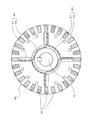
その他のスロットコンビネーションの一例を図11に示す。図11に示す回転子3Aでは、二次導体30の設置数が28個であり、誘導型で見て28P36Sのコンビネーションスロット構成となっている(同期型では4P36Sのまま)。これらのスロットコンビネーション構成に共通している点は、二次導体30の数とスロットの数を相違させている点である。これにより、回転電機1の設計の自由度を向上できる。例えば図11に示す回転子3Aのように、二次導体30の数をスロット数よりも少なくすることで、二次導体30の周方向の離間距離を大きくできるので、界磁磁束を増大した状態において、磁束が第1回転子鉄心21内の磁極間で短絡することを容易に防止できる。
<2.第2実施形態>
次に、第2実施形態について説明する。なお、第2実施形態では、主として上記第1実施形態と異なる部分について説明する。また、上記第1実施形態と実質的に同一の機能を有する構成要素は、原則として同一の符号で表し、これらの構成要素についての重複説明は、適宜省略する。
次に、第2実施形態について説明する。なお、第2実施形態では、主として上記第1実施形態と異なる部分について説明する。また、上記第1実施形態と実質的に同一の機能を有する構成要素は、原則として同一の符号で表し、これらの構成要素についての重複説明は、適宜省略する。
(2-1.回転電機の構成)
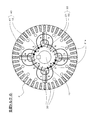
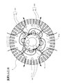
まず、図12、図13を参照しつつ、本実施形態の回転電機1Aの構成の一例について説明する。図12は、上記図2に対応する本実施形態の回転電機1Aの軸直交断面の一例を示しており、図13は図12中の回転子3Bだけを拡大して示している。なお、図12、図13中に示す回転電機1Aの各構成の状態は、回転速度が小さい場合に対応する。
まず、図12、図13を参照しつつ、本実施形態の回転電機1Aの構成の一例について説明する。図12は、上記図2に対応する本実施形態の回転電機1Aの軸直交断面の一例を示しており、図13は図12中の回転子3Bだけを拡大して示している。なお、図12、図13中に示す回転電機1Aの各構成の状態は、回転速度が小さい場合に対応する。
まず図12において、固定子2の構成は上記第1実施形態と同一であり、回転子3Bの構成が上記第1実施形態と相違している。図13に示すように、本実施形態における回転子3Bは、略円筒状の回転子鉄心23と、回転子鉄心23の中心に同軸となるよう固定されたシャフト10Aと、複数の二次導体30(図示の例では44個)と、複数(図示の例では8個)の永久磁石40とを備える。なお、特に図示しないが、本実施形態では回転子3Bは極数に対応した相対角度規制機構50を備えていることは第1実施形態と同様である。
本実施形態では、シャフト10Aは上記第1実施形態のシャフト10よりも大きな外径で形成された非磁性体の軸体であり、回転子鉄心23はこのシャフト10Aと共に回転する。回転子3Bが備える複数の永久磁石40のうちの4個は、回転子鉄心23の内部に放射状に固定配置された第4永久磁石44である。その他の4個の永久磁石40は、周方向において各第4永久磁石44の間に放射状に配置され、第4永久磁石44よりも径方向内側に移動可能に配置された第5永久磁石45である。本実施形態では、第4永久磁石44と第5永久磁石45のそれぞれの径方向長さが略同じであり、周方向に隣り合う第4永久磁石44と第5永久磁石45とは、同じ磁極が周方向に対向するように配置されている。第5永久磁石45は、そのほぼ全体がシャフト10Aの内部に入り込む内周側位置から、第4永久磁石44と同じ径方向位置まで移動可能であり、それぞれコイルバネ16(弾性部材の一例)によって径方向内側に向けて押圧されている。
(2-2.回転速度に応じて界磁磁束と磁石トルクが変化する原理)
図14、図15を参照しつつ、回転速度に応じて界磁磁束が変化する原理の一例について説明する。図14は、停止時を含めて回転速度が小さい状態を示している。この低速運転状態では、第4永久磁石44との間の斥力とコイルバネ16による押圧力によって第5永久磁石45が第4永久磁石44よりも径方向内側の位置(シャフト10Aの内部)に保持される。この状態では、第5永久磁石45の磁束は非磁性体のシャフト10Aの内部で循環し、第4永久磁石44のほとんどの磁束が周方向に沿った経路を介して隣り合う第4永久磁石44の間で循環し、これら永久磁石40から発生する界磁磁束の量が最小となる。これにより、回転子3Bの停止時には起動トルクとしての誘導トルクが最大に得られる。
図14、図15を参照しつつ、回転速度に応じて界磁磁束が変化する原理の一例について説明する。図14は、停止時を含めて回転速度が小さい状態を示している。この低速運転状態では、第4永久磁石44との間の斥力とコイルバネ16による押圧力によって第5永久磁石45が第4永久磁石44よりも径方向内側の位置(シャフト10Aの内部)に保持される。この状態では、第5永久磁石45の磁束は非磁性体のシャフト10Aの内部で循環し、第4永久磁石44のほとんどの磁束が周方向に沿った経路を介して隣り合う第4永久磁石44の間で循環し、これら永久磁石40から発生する界磁磁束の量が最小となる。これにより、回転子3Bの停止時には起動トルクとしての誘導トルクが最大に得られる。
なお、上記界磁磁束が「最小」の状態とは、第4永久磁石44と第5永久磁石45とが上記図14に示した配置状態、すなわち第5永久磁石45が径方向内側に移動して周方向に隣り合う第4永久磁石同士の間に実質的に位置しない状態における、界磁磁束の状態をいう。
そして回転子3Bの回転速度が所定速度を超えた高速運転時には、図15に示すように、第5永久磁石45がそれ自体に負荷される遠心力によって第4永久磁石44との斥力とコイルバネ16の押圧力に抗して外周側へ移動する。その結果、第5永久磁石45は第4永久磁石44と径方向で重複する位置に位置することになる。この配置変更過程では、上記停止時の場合と比較して各永久磁石40の磁束の流通経路が変更され、第4、第5永久磁石44,45からの界磁磁束の量が増大する。つまり、周方向に隣り合う第4永久磁石44と第5永久磁石45の間の領域が磁極部23aとして構成され、各磁極部23aから回転子3Bの外周側に放出する界磁磁束が増大する。これにより、回転子3Bの高速回転時には、停止時よりも磁石トルクを増大させて同期運転時の駆動トルクが増大する。
第5永久磁石45が外周側へ移動し始める上記の所定速度は、コイルバネ16の弾性係数や第5永久磁石45自体の質量(遠心力)及び第4、第5永久磁石44,45の磁化強度(斥力)等により調整できる。そしてこの所定速度を、上記図9に示した誘導運転の安定速度領域内に設定することで、上記第1実施形態と同様に誘導運転と同期運転の円滑な切り替えが可能となる。
(2-3.第2実施形態による効果)
以上説明した本実施形態の回転電機1Aでは、回転子鉄心23に放射状に固定配置された複数の第4永久磁石44と、周方向において複数の第4永久磁石44の間に放射状に配置され、第4永久磁石44よりも径方向内側に移動可能に配置された複数の第5永久磁石45と、を有する。また、第4永久磁石44と第5永久磁石45とは、同じ磁極が周方向に対向するように配置されている。このような構成により、上記図14、図15に示したように各永久磁石40の磁束の流通経路が変更され、回転速度に応じた界磁磁束と磁石トルクの変化が可能になる。
以上説明した本実施形態の回転電機1Aでは、回転子鉄心23に放射状に固定配置された複数の第4永久磁石44と、周方向において複数の第4永久磁石44の間に放射状に配置され、第4永久磁石44よりも径方向内側に移動可能に配置された複数の第5永久磁石45と、を有する。また、第4永久磁石44と第5永久磁石45とは、同じ磁極が周方向に対向するように配置されている。このような構成により、上記図14、図15に示したように各永久磁石40の磁束の流通経路が変更され、回転速度に応じた界磁磁束と磁石トルクの変化が可能になる。
また、本実施形態では特に、複数の第5永久磁石45は、回転子3Bが所定回転速度(例えば図9における1720min-1)より低い低速回転時では複数の第4永久磁石44よりも径方向内側に位置する。そして、回転子3Bが上記所定回転速度より高い高速回転時では、複数の第5永久磁石45が複数の第4永久磁石44と径方向で重複する位置に位置する。これにより、上記所定回転速度を基準として磁束の通過経路とトルク種類の変更が可能となり、同期運転を円滑に開始できる。
また、本実施形態では特に、回転子3Bは、複数の第5永久磁石45をそれぞれ径方向内側に押圧する複数のコイルバネ16を有する。この構成において、コイルバネ16の弾性係数を調整することで、回転速度に応じた第5永久磁石45の径方向位置の調整が可能となる。これにより、回転速度に応じた磁石トルクの調整が可能となり、誘導トルクと磁石トルクとの切り替えを行う所定回転速度の調整も当該回転電機1Aの製造時で可能となる。なお、この所定回転速度の調整は、他にも設計段階での第5永久磁石45の質量(遠心力)と第4、第5永久磁石44,45の磁化強度(斥力)等によっても調整可能である。
なお、以上の説明において、外観上の寸法や大きさ、形状、位置等が「同じ」「等しい」等の記載がある場合は、当該記載は厳密な意味ではない。すなわち、それら「同じ」「等しい」とは、設計上、製造上の公差、誤差が許容され、「実質的に同じ」「実質的に等しい」という意味である。
また、以上既に述べた以外にも、上記各実施形態や各変形例による手法を適宜組み合わせて利用してもよい。その他、一々例示はしないが、上記各実施形態や各変形例は、その趣旨を逸脱しない範囲内において、種々の変更が加えられて実施されるものである。
1,1A 回転電機
2 固定子
3,3A,3B 回転子
5 固定子鉄心
7 固定子巻線(巻線の一例)
10,10A シャフト
16 コイルバネ(弾性部材の一例)
20 回転子鉄心(第1回転子鉄心、第2回転子鉄心の一例)
21 第1回転子鉄心
21a 磁極部
22 第2回転子鉄心
23 回転子鉄心
23a 磁極部
30 二次導体
40 永久磁石(第1永久磁石、第2永久磁石、第4永久磁石、第5永久磁石の一例)
41 第1永久磁石
42 第2永久磁石
44 第4永久磁石
45 第5永久磁石
50 相対角度規制機構
51 第1負荷側側板(第1プレートの一例)
52 第1反負荷側側板(第1プレートの一例)
53 第2負荷側側板(第2プレートの一例)
54 第2反負荷側側板(第2プレートの一例)
56 第1突起部
57 第2突起部
58 可動堰部
59 チャンバ
60 グリス(非圧縮性流体の一例)
2 固定子
3,3A,3B 回転子
5 固定子鉄心
7 固定子巻線(巻線の一例)
10,10A シャフト
16 コイルバネ(弾性部材の一例)
20 回転子鉄心(第1回転子鉄心、第2回転子鉄心の一例)
21 第1回転子鉄心
21a 磁極部
22 第2回転子鉄心
23 回転子鉄心
23a 磁極部
30 二次導体
40 永久磁石(第1永久磁石、第2永久磁石、第4永久磁石、第5永久磁石の一例)
41 第1永久磁石
42 第2永久磁石
44 第4永久磁石
45 第5永久磁石
50 相対角度規制機構
51 第1負荷側側板(第1プレートの一例)
52 第1反負荷側側板(第1プレートの一例)
53 第2負荷側側板(第2プレートの一例)
54 第2反負荷側側板(第2プレートの一例)
56 第1突起部
57 第2突起部
58 可動堰部
59 チャンバ
60 グリス(非圧縮性流体の一例)
Claims (17)
- 巻線を備えた固定子と回転子とを有する回転電機であって、
前記回転子は、
回転子鉄心と、
前記回転子鉄心に配置された複数の永久磁石と、
前記回転子鉄心の前記複数の永久磁石よりも径方向外側に配置され、前記固定子の回転磁界とのすべりにより誘導電流が流れる複数の二次導体と、を有し、
前記複数の永久磁石による前記巻線に鎖交する界磁磁束が変化するように構成される
ことを特徴とする回転電機。 - 前記回転子は、
回転数に応じて前記複数の永久磁石の配置を変更するように構成される
ことを特徴とする請求項1記載の回転電機。 - 前記回転子は、
停止時では前記界磁磁束を最小とし、所定回転数より高い高速回転時では前記停止時よりも前記界磁磁束を増加させるように構成される
ことを特徴とする請求項1又は2に記載の回転電機。 - 前記回転子鉄心は、
第1回転子鉄心と、
前記第1回転子鉄心の前記径方向内側に配置され、前記第1回転子鉄心と相対回転可能な第2回転子鉄心と、を有し、
前記複数の永久磁石は、
同じ磁極が周方向に対向するように前記第1回転子鉄心の内部に放射状に配置された複数の第1永久磁石と、
前記複数の第1永久磁石により前記第1回転子鉄心に構成される複数の磁極部と同数の磁極を備え、前記磁極が前記周方向に沿って交互に異なるように前記第2回転子鉄心の外周に配置された少なくとも1つの第2永久磁石と、を有する
ことを特徴とする請求項1乃至3のいずれか1項に記載の回転電機。 - 前記複数の二次導体は、
非磁性体で構成され、
前記第1永久磁石と前記周方向で重複する位置に配置された前記二次導体を含む
ことを特徴とする請求項4記載の回転電機。 - 前記複数の二次導体は、
前記第1回転子鉄心において前記周方向に等間隔で配置され、
1つの前記磁極部に対応する複数の前記二次導体の間の前記周方向の離間距離の合計は、前記1つの磁極部を囲む2つの第1永久磁石のそれぞれの径方向寸法と1つの第2永久磁石の周方向寸法の合計の半分より大きくなるように設定されている
ことを特徴とする請求項4又は5記載の回転電機。 - 前記回転子は、
前記第1回転子鉄心と前記第2回転子鉄心との相対角度の変動範囲を、前記第2永久磁石の磁極ピッチ以下の角度範囲に規制する相対角度規制機構を有する
ことを特徴とする請求項4乃至6のいずれか1項に記載の回転電機。 - 前記相対角度規制機構は、
前記第1回転子鉄心の軸方向の少なくとも一方側端部に固定された第1プレートと、
前記第1プレートにおいて径方向内側に向けて突出した少なくとも1つの第1突起部と、
前記第2回転子鉄心の軸方向の少なくとも前記一方側端部に固定された第2プレートと、
前記第2プレートにおいて径方向外側に向けて突出し、前記第1突起部と前記周方向で接触可能な少なくとも1つの第2突起部と、
を有することを特徴とする請求項7記載の回転電機。 - 前記相対角度規制機構は、
前記第1プレートの内周面と、前記第2プレートの外周面との間に形成され、内部に非圧縮性流体を満たしたチャンバと、
前記第1突起部の内部で径方向に移動することで前記チャンバを前記周方向に区画可能な可動堰部と、
を有することを特徴とする請求項8記載の回転電機。 - 前記可動堰部は、
第3永久磁石で構成され、
前記回転子が所定回転数より低い低速回転時では前記第2プレートの外周面に接触して前記チャンバを前記周方向に区画し、
前記回転子が前記所定回転数より高い高速回転時では前記第2プレートの外周面から離間して前記チャンバを前記周方向に連通させる
ことを特徴とする請求項9記載の回転電機。 - 前記複数の永久磁石は、
前記回転子鉄心に放射状に固定配置された複数の第4永久磁石と、
周方向において前記複数の第4永久磁石の間に放射状に配置され、前記第4永久磁石よりも径方向内側に移動可能に配置された複数の第5永久磁石と、を有し、
前記第4永久磁石と前記第5永久磁石とは、同じ磁極が前記周方向に対向するように配置されている
ことを特徴とする請求項1乃至3のいずれか1項に記載の回転電機。 - 前記複数の第5永久磁石は、
前記回転子が所定回転数より低い低速回転時では前記複数の第4永久磁石よりも径方向内側に位置し、
前記回転子が前記所定回転数より高い高速回転時では前記複数の第4永久磁石と径方向で重複する位置に位置する
ことを特徴とする請求項11記載の回転電機。 - 前記回転子は、
前記複数の第5永久磁石をそれぞれ前記径方向内側に向けて押圧する複数の弾性部材を有する
ことを特徴とする請求項11又は12記載の回転電機。 - 前記複数の二次導体は、
非磁性体で構成され、
前記第4永久磁石と前記周方向で重複する位置に配置された前記二次導体を含む
ことを特徴とする請求項11乃至13のいずれか1項に記載の回転電機。 - 前記固定子は、
前記巻線が収容される複数のスロットを備えた固定子鉄心を有し、
前記複数の二次導体の数は、
前記スロットの数と異なる
ことを特徴とする請求項1乃至14のいずれか1項に記載の回転電機。 - 巻線を備えた固定子と回転子とを有する回転電機であって、
前記回転子は、
回転子鉄心と、
前記回転子鉄心に配置された複数の永久磁石と、
前記回転子鉄心の前記複数の永久磁石よりも径方向外側に配置され、前記固定子の回転磁界とのすべりにより誘導電流が流れる複数の二次導体と、を有し、
前記複数の永久磁石による前記巻線に鎖交する界磁磁束が変化するように構成されており、
前記回転子鉄心は、
第1回転子鉄心と、
前記第1回転子鉄心の前記径方向内側に配置され、前記第1回転子鉄心と相対回転可能な第2回転子鉄心と、を有し、
前記複数の永久磁石は、
同じ磁極が周方向に対向するように前記第1回転子鉄心の内部に放射状に配置された複数の第1永久磁石と、
前記複数の第1永久磁石により前記第1回転子鉄心に構成される複数の磁極部と同数の磁極を備え、前記磁極が前記周方向に沿って交互に異なるように前記第2回転子鉄心の外周に配置された少なくとも1つの第2永久磁石と、を有し、
前記複数の二次導体は、
前記第1回転子鉄心において前記周方向に等間隔で配置され、
1つの前記磁極部に対応する複数の前記二次導体の間の前記周方向の離間距離の合計は、前記1つの磁極部を囲む2つの第1永久磁石のそれぞれの径方向寸法と1つの第2永久磁石の周方向寸法の合計の半分より大きくなるように設定されている
ことを特徴とする回転電機。 - 巻線を備えた固定子と回転子とを有する回転電機であって、
前記回転子は、
回転子鉄心と、
前記回転子鉄心に配置された複数の永久磁石と、
前記回転子鉄心の前記複数の永久磁石よりも径方向外側に配置され、前記固定子の回転磁界とのすべりにより誘導電流が流れる複数の二次導体と、を有し、
前記複数の永久磁石による前記巻線に鎖交する界磁磁束が変化するように構成されており、
前記複数の永久磁石は、
前記回転子鉄心に放射状に固定配置された複数の第4永久磁石と、
周方向において前記複数の第4永久磁石の間に放射状に配置され、前記第4永久磁石よりも径方向内側に移動可能に配置された複数の第5永久磁石と、を有し、
前記第4永久磁石と前記第5永久磁石とは、同じ磁極が前記周方向に対向するように配置されており、
前記複数の第5永久磁石は、
前記回転子が所定回転数より低い低速回転時では前記複数の第4永久磁石よりも径方向内側に位置し、
前記回転子が前記所定回転数より高い高速回転時では前記複数の第4永久磁石と径方向で重複する位置に位置する
ことを特徴とする回転電機。
Priority Applications (1)
| Application Number | Priority Date | Filing Date | Title |
|---|---|---|---|
| PCT/JP2015/083258 WO2017090159A1 (ja) | 2015-11-26 | 2015-11-26 | 回転電機 |
Applications Claiming Priority (1)
| Application Number | Priority Date | Filing Date | Title |
|---|---|---|---|
| PCT/JP2015/083258 WO2017090159A1 (ja) | 2015-11-26 | 2015-11-26 | 回転電機 |
Publications (1)
| Publication Number | Publication Date |
|---|---|
| WO2017090159A1 true WO2017090159A1 (ja) | 2017-06-01 |
Family
ID=58763379
Family Applications (1)
| Application Number | Title | Priority Date | Filing Date |
|---|---|---|---|
| PCT/JP2015/083258 Ceased WO2017090159A1 (ja) | 2015-11-26 | 2015-11-26 | 回転電機 |
Country Status (1)
| Country | Link |
|---|---|
| WO (1) | WO2017090159A1 (ja) |
Cited By (7)
| Publication number | Priority date | Publication date | Assignee | Title |
|---|---|---|---|---|
| CN109462319A (zh) * | 2018-11-15 | 2019-03-12 | 山东大学 | 无刷混合磁极式同步发电机及其方法 |
| CN112134382A (zh) * | 2020-09-23 | 2020-12-25 | 上海电机学院 | 一种异步起动的永磁同步电动机的转子结构 |
| CN112821615A (zh) * | 2021-02-24 | 2021-05-18 | 上海电机学院 | 一种用于切向充磁的永磁同步电机弱磁扩速的转子结构 |
| WO2021256125A1 (ja) | 2020-06-18 | 2021-12-23 | 株式会社 東芝 | 回転電機 |
| EP4465491A1 (en) * | 2023-05-15 | 2024-11-20 | Mazda Motor Corporation | Vehicle drive system |
| EP4464538A1 (en) * | 2023-05-15 | 2024-11-20 | Mazda Motor Corporation | Vehicle drive system |
| EP4465508A3 (en) * | 2023-05-15 | 2024-11-27 | Mazda Motor Corporation | Vehicle drive system |
Citations (6)
| Publication number | Priority date | Publication date | Assignee | Title |
|---|---|---|---|---|
| JPS54148214A (en) * | 1978-05-13 | 1979-11-20 | Hitachi Ltd | Permanent-magnet-type synchronous motor |
| JPS55133654A (en) * | 1979-04-02 | 1980-10-17 | Shinko Electric Co Ltd | Rotor of permanent-magnet-type inductive synchronous motor and manufacturing method thereof |
| JPH0965591A (ja) * | 1995-08-24 | 1997-03-07 | Toyota Motor Corp | 永久磁石モータ |
| JP2004072978A (ja) * | 2002-08-09 | 2004-03-04 | Equos Research Co Ltd | 電動機 |
| JP2008072849A (ja) * | 2006-09-14 | 2008-03-27 | Mitsubishi Electric Corp | 永久磁石式回転電機 |
| JP2013509856A (ja) * | 2009-10-30 | 2013-03-14 | ルイ フィンクル | 誘導式から同期式へ構成変更可能なモータ |
-
2015
- 2015-11-26 WO PCT/JP2015/083258 patent/WO2017090159A1/ja not_active Ceased
Patent Citations (6)
| Publication number | Priority date | Publication date | Assignee | Title |
|---|---|---|---|---|
| JPS54148214A (en) * | 1978-05-13 | 1979-11-20 | Hitachi Ltd | Permanent-magnet-type synchronous motor |
| JPS55133654A (en) * | 1979-04-02 | 1980-10-17 | Shinko Electric Co Ltd | Rotor of permanent-magnet-type inductive synchronous motor and manufacturing method thereof |
| JPH0965591A (ja) * | 1995-08-24 | 1997-03-07 | Toyota Motor Corp | 永久磁石モータ |
| JP2004072978A (ja) * | 2002-08-09 | 2004-03-04 | Equos Research Co Ltd | 電動機 |
| JP2008072849A (ja) * | 2006-09-14 | 2008-03-27 | Mitsubishi Electric Corp | 永久磁石式回転電機 |
| JP2013509856A (ja) * | 2009-10-30 | 2013-03-14 | ルイ フィンクル | 誘導式から同期式へ構成変更可能なモータ |
Cited By (8)
| Publication number | Priority date | Publication date | Assignee | Title |
|---|---|---|---|---|
| CN109462319A (zh) * | 2018-11-15 | 2019-03-12 | 山东大学 | 无刷混合磁极式同步发电机及其方法 |
| WO2021256125A1 (ja) | 2020-06-18 | 2021-12-23 | 株式会社 東芝 | 回転電機 |
| KR20220152311A (ko) | 2020-06-18 | 2022-11-15 | 가부시끼가이샤 도시바 | 회전 전기 기기 |
| CN112134382A (zh) * | 2020-09-23 | 2020-12-25 | 上海电机学院 | 一种异步起动的永磁同步电动机的转子结构 |
| CN112821615A (zh) * | 2021-02-24 | 2021-05-18 | 上海电机学院 | 一种用于切向充磁的永磁同步电机弱磁扩速的转子结构 |
| EP4465491A1 (en) * | 2023-05-15 | 2024-11-20 | Mazda Motor Corporation | Vehicle drive system |
| EP4464538A1 (en) * | 2023-05-15 | 2024-11-20 | Mazda Motor Corporation | Vehicle drive system |
| EP4465508A3 (en) * | 2023-05-15 | 2024-11-27 | Mazda Motor Corporation | Vehicle drive system |
Similar Documents
| Publication | Publication Date | Title |
|---|---|---|
| WO2017090159A1 (ja) | 回転電機 | |
| JP5688684B2 (ja) | 回転電機 | |
| CN101897108A (zh) | 电动机以及旋转电机用转子 | |
| KR20080096407A (ko) | 전기 기기 및 이에 구비되는 로터 | |
| US10355568B2 (en) | Flux control of permanent magnet electric machine | |
| JP2016174521A (ja) | 単相ブラシレスモータ | |
| JP2017063599A (ja) | 単相ブラシレスモータ及びこれを利用する動力工具 | |
| JP2019097359A (ja) | 磁束可変機構付の回転電機 | |
| JP2020120444A (ja) | 回転電機のロータおよび回転電機 | |
| JP2017051055A (ja) | 回転電機 | |
| JP6164506B2 (ja) | 回転電機 | |
| WO2016060232A1 (ja) | ダブルステータ型回転機 | |
| JP2012165540A (ja) | 回転電機 | |
| JP2019041450A (ja) | 回転電機 | |
| JP6895909B2 (ja) | ハイブリッド界磁式ダブルギャップ同期機 | |
| JP6201405B2 (ja) | 回転電機 | |
| JP5673438B2 (ja) | 回転電機のロータ構造 | |
| JP6877944B2 (ja) | 同期リラクタンス型回転電機 | |
| CN113615041A (zh) | 旋转电机 | |
| JP2019154140A (ja) | 回転電機 | |
| JP2019017208A (ja) | 回転子及び永久磁石式回転電機 | |
| JP2016178801A (ja) | スイッチトリラクタンス回転機、及び回転装置 | |
| RU2435282C2 (ru) | Двигатель, структура ротора и магнитная машина | |
| CN112104121B (zh) | 转子及旋转电机 | |
| KR20200085125A (ko) | 모터용 회전자 |
Legal Events
| Date | Code | Title | Description |
|---|---|---|---|
| 121 | Ep: the epo has been informed by wipo that ep was designated in this application |
Ref document number: 15909276 Country of ref document: EP Kind code of ref document: A1 |
|
| NENP | Non-entry into the national phase |
Ref country code: DE |
|
| 122 | Ep: pct application non-entry in european phase |
Ref document number: 15909276 Country of ref document: EP Kind code of ref document: A1 |
|
| NENP | Non-entry into the national phase |
Ref country code: JP |