WO2017073590A1 - 切削インサート、切削工具及び切削加工物の製造方法 - Google Patents
切削インサート、切削工具及び切削加工物の製造方法 Download PDFInfo
- Publication number
- WO2017073590A1 WO2017073590A1 PCT/JP2016/081674 JP2016081674W WO2017073590A1 WO 2017073590 A1 WO2017073590 A1 WO 2017073590A1 JP 2016081674 W JP2016081674 W JP 2016081674W WO 2017073590 A1 WO2017073590 A1 WO 2017073590A1
- Authority
- WO
- WIPO (PCT)
- Prior art keywords
- cutting edge
- cutting
- insert
- edge
- honing
- Prior art date
- Legal status (The legal status is an assumption and is not a legal conclusion. Google has not performed a legal analysis and makes no representation as to the accuracy of the status listed.)
- Ceased
Links
Images









Classifications
-
- B—PERFORMING OPERATIONS; TRANSPORTING
- B23—MACHINE TOOLS; METAL-WORKING NOT OTHERWISE PROVIDED FOR
- B23C—MILLING
- B23C5/00—Milling-cutters
- B23C5/16—Milling-cutters characterised by physical features other than shape
- B23C5/20—Milling-cutters characterised by physical features other than shape with removable cutter bits or teeth or cutting inserts
- B23C5/202—Plate-like cutting inserts with special form
-
- B—PERFORMING OPERATIONS; TRANSPORTING
- B23—MACHINE TOOLS; METAL-WORKING NOT OTHERWISE PROVIDED FOR
- B23B—TURNING; BORING
- B23B27/00—Tools for turning or boring machines; Tools of a similar kind in general; Accessories therefor
- B23B27/14—Cutting tools of which the bits or tips or cutting inserts are of special material
-
- B—PERFORMING OPERATIONS; TRANSPORTING
- B23—MACHINE TOOLS; METAL-WORKING NOT OTHERWISE PROVIDED FOR
- B23B—TURNING; BORING
- B23B27/00—Tools for turning or boring machines; Tools of a similar kind in general; Accessories therefor
- B23B27/14—Cutting tools of which the bits or tips or cutting inserts are of special material
- B23B27/141—Specially shaped plate-like cutting inserts, i.e. length greater or equal to width, width greater than or equal to thickness
- B23B27/145—Specially shaped plate-like cutting inserts, i.e. length greater or equal to width, width greater than or equal to thickness characterised by having a special shape
-
- B—PERFORMING OPERATIONS; TRANSPORTING
- B23—MACHINE TOOLS; METAL-WORKING NOT OTHERWISE PROVIDED FOR
- B23B—TURNING; BORING
- B23B2200/00—Details of cutting inserts
- B23B2200/24—Cross section of the cutting edge
- B23B2200/245—Cross section of the cutting edge rounded
-
- B—PERFORMING OPERATIONS; TRANSPORTING
- B23—MACHINE TOOLS; METAL-WORKING NOT OTHERWISE PROVIDED FOR
- B23C—MILLING
- B23C2200/00—Details of milling cutting inserts
- B23C2200/04—Overall shape
- B23C2200/0416—Irregular
-
- B—PERFORMING OPERATIONS; TRANSPORTING
- B23—MACHINE TOOLS; METAL-WORKING NOT OTHERWISE PROVIDED FOR
- B23C—MILLING
- B23C2200/00—Details of milling cutting inserts
- B23C2200/08—Rake or top surfaces
- B23C2200/085—Rake or top surfaces discontinuous
-
- B—PERFORMING OPERATIONS; TRANSPORTING
- B23—MACHINE TOOLS; METAL-WORKING NOT OTHERWISE PROVIDED FOR
- B23C—MILLING
- B23C2200/00—Details of milling cutting inserts
- B23C2200/12—Side or flank surfaces
- B23C2200/125—Side or flank surfaces discontinuous
-
- B—PERFORMING OPERATIONS; TRANSPORTING
- B23—MACHINE TOOLS; METAL-WORKING NOT OTHERWISE PROVIDED FOR
- B23C—MILLING
- B23C2200/00—Details of milling cutting inserts
- B23C2200/24—Cross section of the cutting edge
- B23C2200/246—Cross section of the cutting edge rounded
-
- B—PERFORMING OPERATIONS; TRANSPORTING
- B23—MACHINE TOOLS; METAL-WORKING NOT OTHERWISE PROVIDED FOR
- B23C—MILLING
- B23C2226/00—Materials of tools or workpieces not comprising a metal
- B23C2226/12—Boron nitride
- B23C2226/125—Boron nitride cubic [CBN]
-
- B—PERFORMING OPERATIONS; TRANSPORTING
- B23—MACHINE TOOLS; METAL-WORKING NOT OTHERWISE PROVIDED FOR
- B23C—MILLING
- B23C2226/00—Materials of tools or workpieces not comprising a metal
- B23C2226/31—Diamond
- B23C2226/315—Diamond polycrystalline [PCD]
Definitions
- the present disclosure relates to a throw-away type cutting insert, a cutting tool, and a manufacturing method of a cut workpiece used in turning processing such as outer diameter processing or turning processing such as milling.
- the cutting insert (throw away tip) described in Patent Document 1 is known as a tool used for milling.
- the cutting insert described in Patent Document 1 has a configuration in which a chamfer is provided between a main cutting edge and a sub cutting edge, and a chamfer which is a kind of honing is provided along the chamfering section.
- the chamfer in the chamfered portion has a linear shape.
- the secondary cutting edge functions as a so-called wiper blade.
- the chamfer in the cutting insert described in Patent Document 1 has a linear shape and is separated from the main cutting edge. Therefore, while the strength of the chamfered portion is good, the strength of the main cutting edge may be insufficient.
- the cutting insert according to the present disclosure includes a corner portion, a first surface having first and second sides extending from the corner portion, a second surface connected to the first surface, the first surface, and the second surface.
- the cutting edge includes a first cutting edge located on the first side, a second cutting edge located on the second side, and a third cutting edge located on the corner. Honing is provided on the first cutting edge and the third cutting edge. The honing width of the third cutting edge on the second cutting edge side becomes smaller as the distance from the first cutting edge approaches the second cutting edge.
- the cutting tool according to the present disclosure includes a holder having a pocket, and the cutting insert according to the present disclosure described above, which is attached to the pocket so that at least a part of the cutting blade protrudes from the holder.
- the manufacturing method of the cut workpiece according to the present disclosure includes a step of rotating the cutting tool according to the present disclosure described above, a step of bringing the rotating cutting tool into contact with a work material, and the cutting tool as the work material. And a step of separating from.
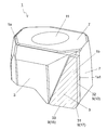
- FIG. 1 is a perspective view illustrating a cutting insert according to a first embodiment of the present disclosure.
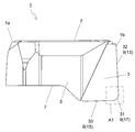
- FIG. 2 is a perspective view from another direction of the cutting insert shown in FIG. 1.
- FIG. 3 is a front view of the first surface of the cutting insert shown in FIG. 1.
- FIG. 4 is an enlarged view of a region A1 in FIG.
- FIG. 5 is an enlarged view of a region A1 in FIG.
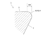
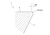
- FIG. 6 is a cross-sectional view along B1-B1 in FIG. 7 is a cross-sectional view along B2-B2 in FIG. 8 is a cross-sectional view along B3-B3 in FIG. 9 is a cross-sectional view along B4-B4 in FIG. 10 is a cross-sectional view along B5-B5 in FIG.
- FIG. 11 is an enlarged view of a portion corresponding to the region A1 of FIG. 3 in the cutting insert according to the second embodiment of the present disclosure.
- FIG. 12 is a perspective view illustrating a cutting insert according to a third embodiment of the present disclosure.
- FIG. 13 is a front view of the first surface of the cutting insert shown in FIG.
- FIG. 14 is an enlarged view of a region A2 in FIG.
- FIG. 15 is a perspective view illustrating a cutting tool according to an embodiment of the present disclosure.
- FIG. 16 is an enlarged view of a region A3 in FIG. 17 is a perspective view from another direction of the cutting tool shown in FIG.
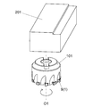
- FIG. 18 is a perspective view showing one step in a method for manufacturing a cut workpiece according to an embodiment of the present disclosure.
- FIG. 19 is a perspective view showing one step in a method for manufacturing a cut workpiece according to an embodiment of the present disclosure.
- FIG. 20 is a perspective view showing one step in a method for manufacturing a cut
- a cutting insert (hereinafter also referred to as an insert) according to an embodiment of the present disclosure will be described in detail with reference to the drawings.
- each drawing referred to below is a simplified illustration of only main members necessary for describing each embodiment for convenience of explanation. Therefore, the cutting insert of this indication may be provided with the arbitrary components which are not shown in each figure to refer.
- the dimension of the member in each figure does not faithfully represent the dimension of the actual component member, the dimension ratio of each member, or the like. These points are the same also in the manufacturing method of the cutting tool and cutting workpiece which are mentioned later.
- the first surface is described as an upper surface
- the second surface is described as a side surface
- the front view of the first surface is described as a top view.
- the insert 1 of this embodiment has the upper surface 3, the lower surface 5, the side surface 7, the cutting edge 9, and the through-hole 11, as shown in FIG.1 and FIG.2, and is used in a rolling process.
- the insert 1 of this embodiment is comprised by the main-body part 1a and the cutting part 1b, and has a polygonal column shape as a whole.
- the main body 1a has a substantially polygonal column shape and has a concave portion 1a1.
- the cutting portion 1b is joined to the concave portion 1a1 using a brazing material or the like.
- hatching by the oblique line is added to the cutting part 1b.
- FIGS. 1 to 10 show an example in which the cutting edge 9 is not formed on the main body 1a but is formed on the cutting portion 1b. Since the insert 1 is configured as shown in FIGS. 1 to 10, the manufacturing cost of the insert 1 can be suppressed while increasing the strength of the cutting edge 9.
- Examples of the material of the main body 1a include cemented carbide or cermet.
- Examples of the composition of the cemented carbide include WC—Co, WC—TiC—Co, and WC—TiC—TaC—Co.
- WC—Co is produced by adding cobalt (Co) powder to tungsten carbide (WC) and sintering.
- WC—TiC—Co is obtained by adding titanium carbide (TiC) to WC—Co.
- WC—TiC—TaC—Co is obtained by adding tantalum carbide (TaC) to WC—TiC—Co.
- cermet is a sintered composite material in which a metal is combined with a ceramic component.
- an example of the cermet is mainly composed of a titanium compound such as titanium carbide (TiC) or titanium nitride (TiN).
- the cutting part 1b is formed of a material with high hardness.
- examples of the material of the cutting part 1b include PCD (polycrystal diamond) or CBN (cubic boron nitride).
- PCD polycrystal diamond
- CBN cubic boron nitride
- the cutting part 1b when it is set as the structure from which the material of the cutting part 1b differs from the material of the main-body part 1a, it is good also considering the cutting part 1b as a material of higher hardness than the main-body part 1a.
- the hardness of the main body 1a and the cutting part 1b can be evaluated by measuring the Vickers hardness of each part.
- the Vickers hardness may be evaluated using a well-known test method in which a pyramid-shaped (regular tetragonal pyramid) indenter made of diamond is pressed into the surface of the material and the dent remaining after the load is removed is measured.
- a dent may be formed in the main body part 1a, while a dent may be hardly formed in the cutting part 1b.
- the surface of the insert 1 may be coated with a film using a chemical vapor deposition (CVD) method or a physical vapor deposition (PVD) method.
- CVD chemical vapor deposition
- PVD physical vapor deposition
- the composition of the coating include titanium carbide (TiC), titanium nitride (TiN), titanium carbonitride (TiCN), and alumina (Al 2 O 3 ).
- the upper surface 3 has a corner portion 31 and a first side 32 and a second side 33 extending from the corner portion 31. More specifically, the upper surface 3 has a polygonal outer periphery in the top view shown in FIG.
- the top view means a state in which the insert 1 is viewed toward the top surface 3.
- the shape of the upper surface 3 of the present embodiment is substantially rectangular.
- the cutting portion 1b is positioned on the upper surface 3 so as to include a corner portion 31 that is one of the four corner portions and two sides (32, 33) extending from the corner portion 31.
- one of the two sides extending from the corner portion 31 is the first side 32, and the other of the two sides extending from the corner portion 31 is the other side. It can be the second side 33.
- the lower surface 5 has a polygonal shape, and has a substantially rectangular shape in the present embodiment, similar to the upper surface 3.
- the cutting part 1b is located on the upper surface 3 side, and is not located on the lower surface 5 side.
- the polygonal shape does not mean a strictly polygonal shape.
- the plurality of corner portions on the upper surface 3 in the present embodiment are not strict corners.
- the corner portion in the present embodiment is a portion sandwiched between sides, and microscopically includes a straight portion and a curved portion.
- the plurality of sides on the upper surface 3 in the present embodiment are not limited to strict linear shapes.
- the plurality of sides may have a slightly convex shape toward the outside or a slightly concave shape in the top view.
- the shape of the upper surface 3 and the lower surface 5 is not limited to said form.
- the shape of the upper surface 3 and the lower surface 5 is substantially rectangular.
- the shape of the upper surface 3 and the lower surface 5 may be, for example, a triangle or a hexagon.
- the side surface 7 is located between the upper surface 3 and the lower surface 5 and is connected to the upper surface 3 and the lower surface 5.
- the side surface 7 is mainly composed of four surfaces. When these four main surfaces are each constituted by a flat surface, the insert 1 can be stably fixed to the holder when the insert 1 is attached to the holder.
- the insert 1 of the present embodiment has a through hole 11 for inserting a screw when the insert 1 is fixed to a holder of a cutting tool with a screw.
- 1 and 2 show an example in which the through hole 11 is formed so as to penetrate the side surface 7, the through hole 11 may be formed so as to penetrate the upper surface 3 and the lower surface 5.
- the through-hole 11 in this embodiment is not formed in the cutting part 1b, but is formed in the main body part 1a. According to such a configuration, the strength of the cutting portion 1b can be maintained high.
- the size of the insert 1 is not particularly limited.
- the length of the long side of the upper surface 3 when viewed from above is set to about 5 to 20 mm.
- the length of the short side of the upper surface 3 is set to about 3 to 10 mm.
- the height from the upper surface 3 to the lower surface 5 is set to about 5 to 20 mm.
- the cutting edge 9 is located in a region where the upper surface 3 and the side surface 7 intersect (hereinafter also referred to as an intersecting region). More specifically, the cutting edge 9 is located in a region where the side surface 7 intersects one corner 31 on the upper surface 3, each of the first side 32 and the second side 33 extending from the corner 31. .
- the cutting portion 1b has a cutting edge 9. From this, when the cutting edge 9 is located in the area
- the cutting edge 9 in the present embodiment has a first cutting edge 13, a second cutting edge 15, and a third cutting edge 17.
- the first cutting edge 13 is located on the first side 32 of the upper surface 3 and has a linear shape.
- the first cutting edge 13 does not have to be located over the entire length of the first side 32.
- the first cutting edge 13 is a part used as a so-called main cutting edge that functions as a main cutting edge when cutting a work material. Therefore, the insert 1 is mounted on the holder of the cutting tool so that the first cutting edge 13 is positioned on the tip side in the feed direction of the cutting tool.
- the length of the first cutting edge 13 is longer than the length of the second cutting edge 15. More specifically, the length of the first cutting edge 13 is longer than the length of each of the second cutting edge 15 and the third cutting edge 17.
- the second cutting edge 15 is located on the second side 33 of the upper surface 3 and has a linear shape. As shown in FIG. 3, the second cutting edge 15 is positioned so as to be orthogonal to the first cutting edge 13 in a top view. The second cutting edge 15 does not need to be positioned over the entire length of the second side 33.
- the second cutting blade 15 is a portion used as a so-called wiper blade that functions as a cutting blade that reduces the surface roughness of the processed surface when cutting a work material. Therefore, the insert 1 is mounted on the holder of the cutting tool so that the second cutting edge 15 is parallel to the feed direction of the cutting tool. Further, as described above, the side of the upper surface 3 may be slightly convex outward as viewed from above. Therefore, for example, the second cutting blade 15 may have one or more curved portions in a top view. Examples of the curved shape include an arc shape. These points are also the same for the first cutting edge 13.
- the third cutting edge 17 is located at the corner 31 of the upper surface 3.
- the corner portion 31 in the present embodiment is microscopically configured by a straight portion and a curved portion.
- the third cutting edge 17 is located at a portion sandwiched between the first side 32 and the second side 33. Then, in the intersecting region, from a change point 321 in the direction of the linear first side 32 extending toward the corner 31 to a change point 331 in the direction of the second side 33 of the linear shape extending toward the corner 31. Is the third cutting edge 17.
- the first cutting edge 13 and the third cutting edge 17 are subjected to so-called honing processing.
- honing processing examples include R honing in which the intersecting region has a curved surface shape, or chamfer honing in which the intersecting region is cut out. Chamfer honing and R honing may be combined.
- the first cutting blade 13 and the third cutting blade 17 are provided with a honing H. Therefore, the strength of the first cutting edge 13 that functions as the main cutting edge can be increased.
- the second cutting edge 15 is a sharp edge where no honing H is provided. Thereby, the 2nd cutting blade 15 is used suitably as a wiper blade. When the second cutting edge 15 is a sharp edge, the surface roughness of the processed surface of the work material can be further reduced. Note that the second cutting blade 15 may be provided with a honing H.
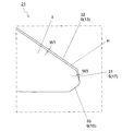
- the honing width W3 on the second cutting edge 15 side of the third cutting edge 17 decreases as the distance from the first cutting edge 13 approaches the second cutting edge 15.
- the honing width W3 on the second cutting edge 15 side of the third cutting edge 17 decreases as the distance from the first cutting edge 13 approaches the second cutting edge 15. This means that the distance from the second cutting edge 15 does not increase as it moves away. Therefore, the honing width W3 on the second cutting edge 15 side in the third cutting edge 17 may be partially constant.
- the area on the second cutting edge 15 side of the third cutting edge 17 may include an area having a constant honing width.
- the second cutting edge 15 side of the third cutting edge 17 is connected to the second cutting edge 15 of the third cutting edge 17 when the third cutting edge 17 is connected to the second cutting edge 15. It means the area near the part.
- This region may include a portion of the third cutting edge 17 that is connected to the second cutting edge 15.
- the third cutting edge 17 when the third cutting edge 17 is not connected to the second cutting edge 15, it means a region in the vicinity of the end portion on the side close to the second cutting edge 15 of both end portions of the third cutting edge 17.
- This region may include an end portion of the third cutting edge 17 on the side close to the second cutting edge 15. Therefore, the ratio of the region on the second cutting edge 15 side of the third cutting edge 17 to the entire third cutting edge 17 is not particularly limited. Therefore, for example, the region on the second cutting edge 15 side in the third cutting edge 17 may be the entire third cutting edge 17. In this case, the entire honing width of the third cutting edge 17 decreases as the distance from the first cutting edge 13 approaches the second cutting edge 15.
- the first cutting blade 13 and the third cutting blade 17 are provided with the honing H, and the honing width W3 on the second cutting blade 15 side of the third cutting blade 17 is changed as described above. Yes.
- the honing width in the region from the first cutting edge 13 to the third cutting edge 17 in the cutting edge 9 can be secured widely.
- the honing width W3 of the third cutting edge 17 is changed as described above, the second cutting edge 15 can be easily sharpened while maintaining the cutting edge strength of the third cutting edge 17. Even if the second cutting edge 15 is provided with the honing H, the honing width from the third cutting edge 17 to the second cutting edge 15 can be reduced. Therefore, the 2nd cutting blade 15 can be functioned favorably as a wiper blade. And each effect mentioned above combines and it becomes the insert 1 with the intensity
- the honing width W3 on the second cutting edge 15 side of the third cutting edge 17 is separated from the first cutting edge 13 to the second cutting edge 15. It gets smaller at a certain rate as it gets closer.
- the inner edge of the honing H on the second cutting edge 15 side of the third cutting edge 17 has a linear shape. With such a configuration, the strength of the third cutting edge 17 is maintained, and the connection with the second cutting edge 15 side, which requires more sharpness, becomes smooth. As a result, both the cutting edge strength and the machined surface accuracy can be improved.
- the honing width W ⁇ b> 3 on the second cutting edge 15 side in the third cutting edge 17 becomes zero at a position spaced from the direction change point 331 on the second side 33.
- the region 171 from the point P that becomes zero to the direction change point 331 in the second side 33 may be a sharp edge.
- the third cutting edge 17 has a sharp edge region 171 between the point P where the honing width W3 on the second cutting edge 15 side of the third cutting edge 17 becomes zero and the second side 33. Also good. According to such a configuration, it is possible to secure a sharp edge area in the vicinity of the change point 331, and thus it is possible to obtain better machining surface accuracy.
- the portion of the third cutting edge 17 on the second cutting edge 15 side may be linear. According to such a structure, the length of the cutting edge 9 used at the time of cutting can be shortened, and possibility that cutting resistance will become large can be reduced.
- the honing width W1 of the first cutting edge 13 may be constant. As described above, the first cutting edge 13 is used as the main cutting edge. Therefore, a relatively large cutting load is easily applied to the first cutting edge 13. When the honing width W1 of the first cutting edge 13 is constant, the strength of the first cutting edge 13 can be increased, so that the durability of the insert 1 can be increased.
- the third cutting edge 17 has a fourth cutting edge 18 located on the first cutting edge 13 side and a fifth cutting edge located on the second cutting edge 15 side. 19 may be included.
- the fourth cutting edge 18 is located between the first cutting edge 13 and the fifth cutting edge 19 and has a linear shape.
- the fifth cutting edge 19 is located between the fourth cutting edge 18 and the second cutting edge 17 and has a linear shape.
- the fourth cutting blade 18 and the fifth cutting blade 19 are provided with a honing H. And in the top view, the honing width W4 in the fourth cutting edge 18 may be constant.
- the fourth cutting edge 18 close to the first cutting edge 13 is likely to be subjected to a larger cutting load than the fifth cutting edge 19.
- the honing width W4 in the fourth cutting edge 18 is constant, the strength is increased over the entire length of the fourth cutting edge 18, so that the durability of the insert 1 can be improved.
- the honing width in the 1st cutting edge 13 and the 4th cutting edge 18 may be the same in the top view
- the honing width W4 in the 4th cutting edge 18 in the top view is the honing width in the 1st cutting edge 13 It may be smaller than W1.
- the first cutting edge 13 is likely to be subjected to a larger cutting load than the fourth cutting edge 18.
- the honing width W4 in the fourth cutting edge 18 is smaller than the honing width W1 in the first cutting edge 13, the possibility that the honing width W4 in the fourth cutting edge 18 becomes larger than necessary is reduced. Therefore, the durability of the insert 1 can be increased while reducing the possibility that the machinability of the fourth cutting edge 18 is excessively lowered.
- the angle ⁇ 1 formed by the first cutting edge 13 and the fourth cutting edge 18 is an obtuse angle in a top view shown in FIG. According to such a configuration, it is possible to reduce the possibility that an excessively large cutting load concentrates on the boundary portion between the first cutting edge 13 and the fourth cutting edge 18. Therefore, the durability of the insert 1 can be increased.
- the angle ⁇ 2 formed by the fourth cutting edge 18 and the fifth cutting edge 19 and the angle ⁇ 3 formed by the fifth cutting edge 19 and the second cutting edge 15 are also obtuse.
- the angle ⁇ 3 formed by the fifth cutting edge 19 and the second cutting edge 15 is an obtuse angle, it is difficult for the cutting load to concentrate on the boundary portion between these cutting edges 9. Therefore, the durability of the insert 1 is enhanced.
- ⁇ 1 is, for example, 135 to 180 °.
- ⁇ 2 is, for example, 100 to 180 °.
- ⁇ 3 is, for example, 135 to 180 °.
- the length L1 of the fifth cutting edge 19 in the direction along the second cutting edge 15 may be longer than the length L2 of the fourth cutting edge 18 in the direction along the second cutting edge 15. According to such a structure, the thickness of the chip
- the type of honing process applied to the first cutting edge 13 and the third cutting edge 17 may be the same or different.
- chamfer honing may be performed on the first cutting edge 13 and R honing may be performed on the third cutting edge 17.
- the first cutting edge 13 may be processed by combining chamfer honing and R honing, and the third cutting edge 17 may be subjected to R honing.
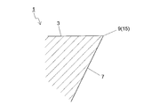
- the honing width of the cutting edge 9 can be evaluated by a top view. If it is difficult to evaluate the honing width of the cutting edge 9 from a top view, it may be evaluated by viewing the insert 1 in a cross section including the cutting edge 9 as shown in FIGS. . 6 to 9 are cross sections orthogonal to the cutting edge 9, respectively.
- the honing width of the cutting edge 9 may be evaluated by, for example, scanning the upper surface 3 using a laser and measuring the height of the upper surface 3 in addition to viewing the insert 1 in cross section. As shown in FIGS. 6 to 9, the honing process applied to the cutting edge 9 may be performed not only on the upper surface 3 side but also on the side surface 7 side. In this case, the honing width on the upper surface 3 side may be larger than the honing width on the side surface 7 side.
- the insert 20 in 2nd Embodiment has the upper surface 3, the lower surface 5, the side surface 7, the cutting blade 9, and the through-hole 11 similarly to the insert 1 of 1st Embodiment.
- the third cutting edge 17 constituting the cutting edge 9 in the first embodiment has two linear portions, a fourth cutting edge 18 and a fifth cutting edge 19, but the third cutting edge in the present embodiment.
- the blade 17 has only one linear part. In other words, as shown in FIG. 11, the third cutting edge 17 of the present embodiment is entirely linear.
- the honing H is provided in the 1st cutting blade 13 and the 3rd cutting blade 17, and the honing width W3 by the side of the 2nd cutting blade 15 in the 3rd cutting blade 17 is separated from the 1st cutting blade 13 in the top view. It gets smaller as it gets closer to the second cutting edge 15. Therefore, similarly to the insert 1 of the first embodiment, the second cutting blade 15 can function well as a wiper blade while maintaining the strength of the first cutting blade 13.
- the insert 21 in the third embodiment has an upper surface 3, a lower surface 5, a side surface 7, a cutting edge 9, and a through hole 11 in the same manner as the insert 1 in the first embodiment.
- the insert 1 of the first embodiment is used for turning, whereas the insert 21 of the third embodiment is used for turning.
- the insert 1 of 1st Embodiment is not limited only to a turning process, It can also be used for a turning process.
- the insert 1 of the first embodiment is constituted by the main body 1a and the cutting part 1b, whereas the insert 21 of the third embodiment is constituted only by the substantially polygonal columnar cutting part 1b.
- the upper surface 3 in the insert 1 of 1st Embodiment was a rectangular shape, the upper surface 3 of the insert 21 of this embodiment is a rhombus (refer FIG. 13).
- the cutting blade 9 has a first cutting blade 13, a second cutting blade 15, and a third cutting blade 17.
- the first cutting edge 13 is located on the first side 32
- the second cutting edge 15 is located on the second side 33.
- the 3rd cutting edge 17 is located in the corner
- the honing H is provided in the 1st cutting blade 13 and the 3rd cutting blade 17, and the honing width W3 by the side of the 2nd cutting blade 15 in the 3rd cutting blade 17 is separated from the 1st cutting blade 13 in the top view. It gets smaller as it gets closer to the second cutting edge 15. Therefore, similarly to the insert 1 of the first embodiment, the second cutting blade 15 can function well as a wiper blade while maintaining the strength of the first cutting blade 13.
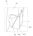
- FIGS. 15 to 17 show a state in which the insert 1 of the first embodiment is attached to the pocket 105 of the holder 103 with screws 107.
- the dashed-two dotted line in FIG.15 and FIG.17 has shown the rotating shaft O1 of the cutting tool 101.
- the cutting tool 101 of the present embodiment is used for a turning process. As shown in FIGS. 15 and 17, the cutting tool 101 includes a holder 103 and a plurality of the inserts 1.
- the holder 103 has a rotation axis O1 and has a plurality of pockets 105 on the outer peripheral surface on the distal end side.
- the insert 1 is attached to the pocket 105.
- the holder 103 has a substantially cylindrical shape with the rotation axis O1 as the center.
- a plurality of pockets 105 are provided on the outer peripheral surface on the distal end side of the holder 103.
- the pocket 105 is a part to which the insert 1 is mounted, and is open to the outer peripheral surface and the front end surface of the holder 103.
- the plurality of pockets 105 are provided at equal intervals, but may be provided at unequal intervals. Note that the holder 103 has a plurality of pockets 105 and thus is not a strict cylindrical shape.
- the insert 1 is mounted in the plurality of pockets 105 of the holder 103.
- the plurality of inserts 1 are mounted such that at least a part of the cutting blade 9 protrudes outward from the holder 103.
- the plurality of inserts 1 in the present embodiment are mounted on the holder 103 so that the first cutting edge 13, the second cutting edge 15, and the third cutting edge 17 protrude from the holder 103 toward the work material. Has been.
- the insert 1 has a pocket so that the upper surface 3 faces the front in the rotation direction of the rotation axis O1 and the lower surface 5 faces the rear in the rotation direction of the rotation axis O1. 105 is attached.
- the upper surface 3 and the lower surface 5 of the insert 1 are not necessarily positioned in the vertical direction in the usage environment of the cutting tool 101.
- the first cutting edge 13 is positioned on the front end side in the feed direction of the cutting tool 101, and the second cutting edge 15 Is positioned parallel to the feed direction of the cutting tool 101.
- the insert 1 is attached to the pocket 105 with a screw 107. That is, the screw 107 is inserted into the through hole 11 of the insert 1, and the tip of the screw 107 is inserted into a screw hole (not shown) formed in the pocket 105 to fix the screw 107 to the screw hole.
- the insert 1 is attached to the holder 103 by fixing the screw 107 in this way.
- steel, cast iron, etc. can be used, for example. Among these materials, steel having high toughness may be used.
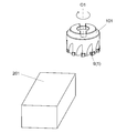
- FIGS. 18 to 20 show a manufacturing method of a cut product when cutting is performed using the cutting tool 101 described above.
- 18 to 20 indicates the rotation axis O1 of the cutting tool 101.
- the cut workpiece is produced by cutting the work material 201.
- the manufacturing method of the cut product in the present embodiment is as follows: (1) a step of rotating the cutting tool 101 represented by the above embodiment; (2) a step of bringing the rotating cutting tool 101 into contact with the work material 201; (3) a step of separating the cutting tool 101 from the work material 201; It has.
- the cutting tool 101 is relatively moved closer to the work material 201 while being rotated around the rotation axis O1.
- the first cutting blade 13, the second cutting blade 15, and the third cutting blade 17 are brought into contact with the work material 201 as the cutting blade 9 in the cutting tool 101, and the work material 201 is moved.
- the cutting tool 101 is relatively moved away from the work material 201.
- the cutting tool 101 including the insert 1 having a good strength of the cutting edge 9 is used, the cutting can be performed in a stable state over a long period of time. Moreover, since the cutting tool 101 provided with the insert 1 having the cutting blade 9 that functions well as a wiper blade is used, it is possible to perform cutting with high processing surface accuracy.
- the work material 201 is fixed and the cutting tool 101 is brought closer to the work material 201. 18 to 20, the work material 201 is fixed and the cutting tool 101 is rotated around the rotation axis O1. In FIG. 20, the work material 201 is fixed and the cutting tool 101 is moved away from the work material 201. Note that, in the cutting in the manufacturing method of the present embodiment, the work material 201 is fixed and the cutting tool 101 is moved in each step, but it is naturally not limited to such a form.
- the work material 201 may be brought close to the cutting tool 101 in the step (1). Similarly, in the step (3), the work material 201 may be moved away from the cutting tool 101. When continuing the cutting process, the state where the cutting tool 101 is rotated and the cutting blade 9 of the insert 1 is brought into contact with a different part of the work material 201 may be repeated.
- Examples of the material of the work material 201 include carbon steel, alloy steel, stainless steel, cast iron, and non-ferrous metal.
- the present disclosure is not limited to the above-described embodiment, and it is needless to say that the embodiment can be arbitrarily set without departing from the gist of the present disclosure.
- Cutting insert (insert) DESCRIPTION OF SYMBOLS 1a ... Main-body part 1a1 ... Concave-shaped part 1b ... Cutting part 3 ... Upper surface (1st surface) 31 ... Corner 32 ... First side 321 ... Direction change point 33 ... Second side 331 ... Direction change point 5 ... Lower surface 7 ... Side surface (second surface) ) 9 ... Cutting blade 11 ... Through hole 13 ... First cutting blade 15 ... Second cutting blade 17 ... Third cutting blade 171 ... Sharp edge region 18 ... Fourth Cutting blade 19 ... Fifth cutting blade 20 ... Cutting insert 21 ... Cutting insert 101 ... Cutting tool 103 ... Holder 105 ... Pocket 107 ... Screw 201 ... Work material H ... Honing
Landscapes
- Engineering & Computer Science (AREA)
- Mechanical Engineering (AREA)
- Milling Processes (AREA)
- Cutting Tools, Boring Holders, And Turrets (AREA)
Abstract
Description
以下、本開示の実施形態に係る切削インサート(以下、インサートともいう)について、図面を用いて詳細に説明する。但し、以下で参照する各図は、説明の便宜上、各実施形態を説明する上で必要な主要部材のみを簡略化して示したものである。したがって、本開示の切削インサートは、参照する各図に示されていない任意の構成部材を備え得る。また、各図中の部材の寸法は、実際の構成部材の寸法及び各部材の寸法比率などを忠実に表したものではない。これらの点は、後述する切削工具及び切削加工物の製造方法においても同様である。なお、以下において、第1面を上面、第2面を側面と記載するとともに、第1面の正面視を上面視と記載して説明する。
本実施形態のインサート1は、図1及び図2に示すように、上面3、下面5、側面7、切刃9及び貫通孔11を有しており、転削加工において用いられる。本実施形態のインサート1は、本体部1a及び切削部1bによって構成されており、全体として多角柱形状になっている。本体部1aは、略多角柱形状であり、凹形状の部分1a1を有している。そして、凹形状の部分1a1に切削部1bがロウ材などを用いて接合されている。なお、視覚的な理解を容易にするため、図1及び図2において、切削部1bに斜線によるハッチングを加えている。
次に、本開示の第2実施形態に係るインサート20について、図11を用いて詳細に説明する。なお、以下においては、第1実施形態のインサート1と相違する部分を中心として説明する。そのため、第1実施形態と同様の構成を有する部分については第1実施形態における説明を援用し、説明を省略する。
次に、本開示の第3実施形態に係るインサート21について、図12~図14を用いて詳細に説明する。なお、以下においては、第1実施形態のインサート1と相違する部分を中心として説明する。そのため、第1実施形態と同様の構成を有する部分については第1実施形態における説明を援用し、説明を省略する。
次に、本開示の一実施形態に係る切削工具101について図15~図17を用いて説明する。図15~図17は、第1実施形態のインサート1がホルダ103のポケット105にネジ107によって取り付けられた状態を示している。なお、図15及び図17における二点鎖線は、切削工具101の回転軸O1を示している。
次に、本開示の一実施形態に係る切削加工物の製造方法について図18~図20を用いて説明する。図18~図20は、上記の切削工具101を用いて切削加工を行った場合の切削加工物の製造方法を示している。なお、図18~図20における二点鎖線は、切削工具101の回転軸O1を示している。
(1)上記実施形態に代表される切削工具101を回転させる工程と、
(2)回転している切削工具101を被削材201に接触させる工程と、
(3)切削工具101を被削材201から離す工程と、
を備えている。
1a・・・本体部
1a1・・・凹形状の部分
1b・・・切削部
3・・・上面(第1面)
31・・・角部
32・・・第1辺
321・・・方向の変化点
33・・・第2辺
331・・・方向の変化点
5・・・下面
7・・・側面(第2面)
9・・・切刃
11・・・貫通孔
13・・・第1切刃
15・・・第2切刃
17・・・第3切刃
171・・・シャープエッジの領域
18・・・第4切刃
19・・・第5切刃
20・・・切削インサート
21・・・切削インサート
101・・・切削工具
103・・・ホルダ
105・・・ポケット
107・・・ネジ
201・・・被削材
H・・・ホーニング
Claims (11)
- 角部並びに前記角部から延びる第1辺及び第2辺を有する第1面と、
前記第1面に接続された第2面と、
前記第1面と前記第2面とが交差する領域に位置する切刃と、を備え、
前記切刃は、前記第1辺に位置する第1切刃と、前記第2辺に位置する第2切刃と、前記角部に位置する第3切刃とを有し、
前記第1切刃及び前記第3切刃にホーニングが設けられ、
前記第3切刃における前記第2切刃側のホーニング幅は、前記第1切刃から離れて前記第2切刃に近付くにつれて小さくなっている、切削インサート。 - 前記第1切刃におけるホーニング幅が一定である、請求項1に記載の切削インサート。
- 前記第2切刃は、シャープエッジである、請求項1又は2に記載の切削インサート。
- 前記第3切刃は、前記第1切刃側に位置するとともに直線形状である第4切刃と前記第2切刃側に位置する第5切刃とを有し、
前記第4切刃におけるホーニング幅が一定である、請求項1~3のいずれかに記載の切削インサート。 - 前記第4切刃におけるホーニング幅が、前記第1切刃におけるホーニング幅よりも小さい、請求項4に記載の切削インサート。
- 前記第1面の正面視において、前記第1切刃と前記第4切刃のなす角θ1、前記第4切刃と前記第5切刃のなす角θ2、及び前記第5切刃と前記第2切刃のなす角θ3が、いずれも鈍角である、請求項4又は5に記載の切削インサート。
- 前記第1面の正面視において、前記第2切刃に沿う方向における前記第5切刃の長さL1は、前記第2切刃に沿う方向における前記第4切刃の長さL2よりも長い、請求項4~6のいずれかに記載の切削インサート。
- 前記第1面の正面視において、前記第3切刃における前記第2切刃側の部分が、直線形状である、請求項1~7のいずれかに記載の切削インサート。
- 前記第1切刃の長さが、前記第2切刃の長さよりも長い、請求項1~8のいずれかに記載の切削インサート。
- ポケットを有するホルダと、
前記切刃の少なくとも一部が前記ホルダから突出するように前記ポケットに装着された、請求項1~9のいずれかに記載の切削インサートと、を備える、切削工具。 - 請求項10に記載の切削工具を回転させる工程と、
回転している前記切削工具を被削材に接触させる工程と、
前記切削工具を前記被削材から離す工程と、を備える、切削加工物の製造方法。
Priority Applications (2)
| Application Number | Priority Date | Filing Date | Title |
|---|---|---|---|
| US15/771,129 US10478901B2 (en) | 2015-10-27 | 2016-10-26 | Cutting insert, cutting tool, and method of manufacturing machined product |
| JP2017547814A JP6685531B2 (ja) | 2015-10-27 | 2016-10-26 | 切削インサート、切削工具及び切削加工物の製造方法 |
Applications Claiming Priority (2)
| Application Number | Priority Date | Filing Date | Title |
|---|---|---|---|
| JP2015-210593 | 2015-10-27 | ||
| JP2015210593 | 2015-10-27 |
Publications (1)
| Publication Number | Publication Date |
|---|---|
| WO2017073590A1 true WO2017073590A1 (ja) | 2017-05-04 |
Family
ID=58630399
Family Applications (1)
| Application Number | Title | Priority Date | Filing Date |
|---|---|---|---|
| PCT/JP2016/081674 Ceased WO2017073590A1 (ja) | 2015-10-27 | 2016-10-26 | 切削インサート、切削工具及び切削加工物の製造方法 |
Country Status (3)
| Country | Link |
|---|---|
| US (1) | US10478901B2 (ja) |
| JP (2) | JP6685531B2 (ja) |
| WO (1) | WO2017073590A1 (ja) |
Cited By (6)
| Publication number | Priority date | Publication date | Assignee | Title |
|---|---|---|---|---|
| JP2019005888A (ja) * | 2017-06-23 | 2019-01-17 | 株式会社タンガロイ | 切削工具 |
| US20190061016A1 (en) * | 2017-08-30 | 2019-02-28 | Tungaloy Corporation | Cutting tool |
| CN109420791A (zh) * | 2017-08-29 | 2019-03-05 | 株式会社泰珂洛 | 切削刀片和切削工具 |
| US20190091772A1 (en) * | 2017-09-28 | 2019-03-28 | Tungaloy Corporation | Cutting tool |
| US20200331070A1 (en) * | 2017-12-14 | 2020-10-22 | Sandvik Intellectual Property Ab | Threading insert having variable edge roundness |
| JPWO2020054702A1 (ja) * | 2018-09-12 | 2021-08-30 | 京セラ株式会社 | 切削インサート、回転工具及び切削加工物の製造方法 |
Families Citing this family (2)
| Publication number | Priority date | Publication date | Assignee | Title |
|---|---|---|---|---|
| DE102020117101A1 (de) | 2020-06-29 | 2021-12-30 | Kennametal Inc. | Schneideinsatz und Zerspanungswerkzeug |
| CN114309682A (zh) * | 2020-09-30 | 2022-04-12 | 肯纳金属公司 | 切削刀片 |
Citations (5)
| Publication number | Priority date | Publication date | Assignee | Title |
|---|---|---|---|---|
| JPH09207007A (ja) * | 1996-01-31 | 1997-08-12 | Mitsubishi Materials Corp | ホーニング付きスローアウェイチップ |
| JP2000513659A (ja) * | 1996-08-21 | 2000-10-17 | インガソル カッティング ツール カンパニー | 変化する幅のランドを有するインサート |
| JP2002192407A (ja) * | 2000-12-26 | 2002-07-10 | Ngk Spark Plug Co Ltd | 切削工具 |
| WO2007039944A1 (ja) * | 2005-10-06 | 2007-04-12 | Sumitomo Electric Hardmetal Corp. | 高品位高能率加工用切削工具およびそれを用いた切削加工方法 |
| WO2010110009A1 (ja) * | 2009-03-24 | 2010-09-30 | 日立ツール株式会社 | 刃先交換式回転工具 |
Family Cites Families (4)
| Publication number | Priority date | Publication date | Assignee | Title |
|---|---|---|---|---|
| JPH08155702A (ja) * | 1994-12-07 | 1996-06-18 | Sumitomo Electric Ind Ltd | チップブレーカ付き切削工具及びその製造方法 |
| EP1188504B1 (en) * | 2000-09-07 | 2004-11-17 | Ngk Spark Plug Co., Ltd | Coated cutting tool |
| JP2004154892A (ja) | 2002-11-06 | 2004-06-03 | Ngk Spark Plug Co Ltd | スローアウェイチップ及び切削工具 |
| JP6338204B1 (ja) * | 2017-08-29 | 2018-06-06 | 株式会社タンガロイ | 切削インサート及び切削工具 |
-
2016
- 2016-10-26 US US15/771,129 patent/US10478901B2/en active Active
- 2016-10-26 JP JP2017547814A patent/JP6685531B2/ja active Active
- 2016-10-26 WO PCT/JP2016/081674 patent/WO2017073590A1/ja not_active Ceased
-
2020
- 2020-03-19 JP JP2020048720A patent/JP2020110915A/ja active Pending
Patent Citations (5)
| Publication number | Priority date | Publication date | Assignee | Title |
|---|---|---|---|---|
| JPH09207007A (ja) * | 1996-01-31 | 1997-08-12 | Mitsubishi Materials Corp | ホーニング付きスローアウェイチップ |
| JP2000513659A (ja) * | 1996-08-21 | 2000-10-17 | インガソル カッティング ツール カンパニー | 変化する幅のランドを有するインサート |
| JP2002192407A (ja) * | 2000-12-26 | 2002-07-10 | Ngk Spark Plug Co Ltd | 切削工具 |
| WO2007039944A1 (ja) * | 2005-10-06 | 2007-04-12 | Sumitomo Electric Hardmetal Corp. | 高品位高能率加工用切削工具およびそれを用いた切削加工方法 |
| WO2010110009A1 (ja) * | 2009-03-24 | 2010-09-30 | 日立ツール株式会社 | 刃先交換式回転工具 |
Cited By (14)
| Publication number | Priority date | Publication date | Assignee | Title |
|---|---|---|---|---|
| JP2019005888A (ja) * | 2017-06-23 | 2019-01-17 | 株式会社タンガロイ | 切削工具 |
| US10525540B2 (en) | 2017-08-29 | 2020-01-07 | Tungaloy Corporation | Cutting insert and cutting tool |
| CN109420791A (zh) * | 2017-08-29 | 2019-03-05 | 株式会社泰珂洛 | 切削刀片和切削工具 |
| JP2019042816A (ja) * | 2017-08-29 | 2019-03-22 | 株式会社タンガロイ | 切削インサート及び切削工具 |
| EP3459665A1 (en) | 2017-08-29 | 2019-03-27 | Tungaloy Corporation | Cutting insert and cutting tool |
| US10507530B2 (en) * | 2017-08-30 | 2019-12-17 | Tungaloy Corporation | Cutting tool |
| US20190061016A1 (en) * | 2017-08-30 | 2019-02-28 | Tungaloy Corporation | Cutting tool |
| US20190091772A1 (en) * | 2017-09-28 | 2019-03-28 | Tungaloy Corporation | Cutting tool |
| US20200331070A1 (en) * | 2017-12-14 | 2020-10-22 | Sandvik Intellectual Property Ab | Threading insert having variable edge roundness |
| JP2021506599A (ja) * | 2017-12-14 | 2021-02-22 | サンドビック インテレクチュアル プロパティー アクティエボラーグ | バリアブルなエッジ真円度を有するスレッディングインサート |
| JP7231632B2 (ja) | 2017-12-14 | 2023-03-01 | サンドビック インテレクチュアル プロパティー アクティエボラーグ | バリアブルなエッジ丸みを有するスレッディングインサート |
| US11772165B2 (en) * | 2017-12-14 | 2023-10-03 | Sandvik Intellectual Property Ab | Threading insert having variable edge roundness |
| JPWO2020054702A1 (ja) * | 2018-09-12 | 2021-08-30 | 京セラ株式会社 | 切削インサート、回転工具及び切削加工物の製造方法 |
| JP7168673B2 (ja) | 2018-09-12 | 2022-11-09 | 京セラ株式会社 | 切削インサート、回転工具及び切削加工物の製造方法 |
Also Published As
| Publication number | Publication date |
|---|---|
| US20180257146A1 (en) | 2018-09-13 |
| JP2020110915A (ja) | 2020-07-27 |
| JPWO2017073590A1 (ja) | 2018-08-09 |
| US10478901B2 (en) | 2019-11-19 |
| JP6685531B2 (ja) | 2020-04-22 |
Similar Documents
| Publication | Publication Date | Title |
|---|---|---|
| JP6685531B2 (ja) | 切削インサート、切削工具及び切削加工物の製造方法 | |
| CN106715015B (zh) | 切削镶刀、切削工具以及切削加工物的制造方法 | |
| JP7304989B2 (ja) | 切削インサート、切削工具及び切削加工物の製造方法 | |
| KR102722565B1 (ko) | 회전 공구 및 절삭 가공물의 제조 방법 | |
| CN107107213A (zh) | 切削镶刀、切削工具以及切削加工物的制造方法 | |
| WO2019065525A1 (ja) | 切削インサート、切削工具及び切削加工物の製造方法 | |
| JPWO2016190351A1 (ja) | 切削インサート、切削工具及びこれを用いた切削加工物の製造方法 | |
| WO2015146956A1 (ja) | 切削インサート、切削工具及び切削加工物の製造方法 | |
| WO2017090770A1 (ja) | 切削インサート、切削工具及び切削加工物の製造方法 | |
| JP6185376B2 (ja) | 切削インサート、切削工具および被削加工物の製造方法 | |
| JP6810807B2 (ja) | 切削インサート、切削工具及び切削加工物の製造方法 | |
| US11383309B2 (en) | Cutting tool and method for manufacturing machined product | |
| JP6352639B2 (ja) | 切削インサート、切削工具および切削加工物の製造方法 | |
| JP6467048B2 (ja) | 切削工具及び切削加工物の製造方法 | |
| WO2019022016A1 (ja) | 切削インサート、切削工具及び切削加工物の製造方法 | |
| JP6449783B2 (ja) | 切削インサート、切削工具及び切削加工物の製造方法 | |
| JPWO2019069916A1 (ja) | 切削インサート、切削工具及び切削加工物の製造方法 | |
| JP2018140449A (ja) | 回転工具 |
Legal Events
| Date | Code | Title | Description |
|---|---|---|---|
| 121 | Ep: the epo has been informed by wipo that ep was designated in this application |
Ref document number: 16859820 Country of ref document: EP Kind code of ref document: A1 |
|
| ENP | Entry into the national phase |
Ref document number: 2017547814 Country of ref document: JP Kind code of ref document: A |
|
| WWE | Wipo information: entry into national phase |
Ref document number: 15771129 Country of ref document: US |
|
| NENP | Non-entry into the national phase |
Ref country code: DE |
|
| 122 | Ep: pct application non-entry in european phase |
Ref document number: 16859820 Country of ref document: EP Kind code of ref document: A1 |