WO2017073569A1 - 流路構造 - Google Patents
流路構造 Download PDFInfo
- Publication number
- WO2017073569A1 WO2017073569A1 PCT/JP2016/081603 JP2016081603W WO2017073569A1 WO 2017073569 A1 WO2017073569 A1 WO 2017073569A1 JP 2016081603 W JP2016081603 W JP 2016081603W WO 2017073569 A1 WO2017073569 A1 WO 2017073569A1
- Authority
- WO
- WIPO (PCT)
- Prior art keywords
- valve
- flow path
- pump
- pilot
- back pressure
- Prior art date
- Legal status (The legal status is an assumption and is not a legal conclusion. Google has not performed a legal analysis and makes no representation as to the accuracy of the status listed.)
- Ceased
Links
Images







Classifications
-
- F—MECHANICAL ENGINEERING; LIGHTING; HEATING; WEAPONS; BLASTING
- F01—MACHINES OR ENGINES IN GENERAL; ENGINE PLANTS IN GENERAL; STEAM ENGINES
- F01P—COOLING OF MACHINES OR ENGINES IN GENERAL; COOLING OF INTERNAL-COMBUSTION ENGINES
- F01P7/00—Controlling of coolant flow
- F01P7/02—Controlling of coolant flow the coolant being cooling-air
-
- F—MECHANICAL ENGINEERING; LIGHTING; HEATING; WEAPONS; BLASTING
- F16—ENGINEERING ELEMENTS AND UNITS; GENERAL MEASURES FOR PRODUCING AND MAINTAINING EFFECTIVE FUNCTIONING OF MACHINES OR INSTALLATIONS; THERMAL INSULATION IN GENERAL
- F16K—VALVES; TAPS; COCKS; ACTUATING-FLOATS; DEVICES FOR VENTING OR AERATING
- F16K31/00—Actuating devices; Operating means; Releasing devices
- F16K31/12—Actuating devices; Operating means; Releasing devices actuated by fluid
- F16K31/36—Actuating devices; Operating means; Releasing devices actuated by fluid in which fluid from the circuit is constantly supplied to the fluid motor
- F16K31/365—Actuating devices; Operating means; Releasing devices actuated by fluid in which fluid from the circuit is constantly supplied to the fluid motor the fluid acting on a diaphragm
-
- F—MECHANICAL ENGINEERING; LIGHTING; HEATING; WEAPONS; BLASTING
- F16—ENGINEERING ELEMENTS AND UNITS; GENERAL MEASURES FOR PRODUCING AND MAINTAINING EFFECTIVE FUNCTIONING OF MACHINES OR INSTALLATIONS; THERMAL INSULATION IN GENERAL
- F16K—VALVES; TAPS; COCKS; ACTUATING-FLOATS; DEVICES FOR VENTING OR AERATING
- F16K31/00—Actuating devices; Operating means; Releasing devices
- F16K31/12—Actuating devices; Operating means; Releasing devices actuated by fluid
- F16K31/36—Actuating devices; Operating means; Releasing devices actuated by fluid in which fluid from the circuit is constantly supplied to the fluid motor
- F16K31/40—Actuating devices; Operating means; Releasing devices actuated by fluid in which fluid from the circuit is constantly supplied to the fluid motor with electrically-actuated member in the discharge of the motor
Definitions
- the present disclosure relates to a flow path structure including a pilot type on-off valve.
- a pilot-type on-off valve is arranged in the middle of the flow channel.
- the on-off valve includes a body, a diaphragm valve, a pilot valve, and an electromagnetic solenoid.
- An inflow passage, an outflow passage, a communication passage, and a pilot passage are formed in the body.
- the diaphragm valve opens and closes a passage interposed between the inflow passage and the outflow passage of the body.
- the communication passage connects the back pressure chamber of the diaphragm valve and the inflow passage.
- the pilot passage connects the back pressure chamber of the diaphragm valve and the outflow passage.
- the pilot valve opens and closes the pilot passage.
- the electromagnetic solenoid opens and closes the pilot valve.
- a heat pump that cools the engine is circulated to a radiator, a heater core, and the like by a mechanical pump that is driven based on engine power.
- the on-off valve may not be properly closed. Details are as follows.
- the pump output also fluctuates accordingly.
- the engine is in a low load state during idle operation at a low engine speed.
- the output of the pump decreases, so the pressure of the heat medium supplied to the on-off valve also decreases.
- the diaphragm valve is closed due to pressure fluctuation in the back pressure chamber when the pilot valve is closed.
- the pressure fluctuation in the back pressure chamber decreases, and as a result, the diaphragm valve may not be properly closed. Similar problems may occur when the diaphragm valve is opened.
- An object of the present disclosure is to provide a flow path structure that can more appropriately open and close a pilot type on-off valve.
- the flow path structure includes a pump that supplies fluid to a device via a supply flow path, and a pilot-type on-off valve that is provided in the supply flow path.
- the on-off valve communicates with the main valve disposed in the supply flow path, the upstream and downstream of the portion of the supply flow path where the pump and the main valve are disposed, and the pilot flow path provided with the back pressure chamber, and the pilot flow And a pilot valve that opens and closes a portion downstream of the back pressure chamber in the road.
- the main valve opens and closes the supply flow path based on a change in the internal pressure of the back pressure chamber accompanying the opening and closing operation of the pilot valve.
- the back pressure chamber when the pilot valve is open, the back pressure chamber includes the flow passage internal pressure in the upstream portion of the portion where the pump and the main valve in the supply flow passage are disposed, and the flow passage in the downstream portion. Pressure corresponding to the pressure difference from the internal pressure is applied. Further, when the pump is stopped, the pump acts as a water flow resistance, so that the internal pressure of the flow path at the pump inlet becomes high and the internal pressure of the flow path at the pump outlet becomes low. Therefore, compared with the case where no pump is present, the internal pressure of the back pressure chamber when the pilot valve is opened can be further reduced by the amount of water flow resistance of the pump.
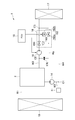
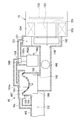
- FIG. 1 is a block diagram showing an outline of a flow path structure of the engine cooling system of the first embodiment.
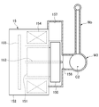
- FIG. 2 is a cross-sectional view showing a cross-sectional structure around the sub pump in the flow channel structure of the first embodiment.
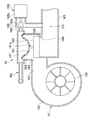
- FIG. 3 is a cross-sectional view showing a cross-sectional structure around a pilot type on-off valve in the flow channel structure of the first embodiment.
- FIG. 4 is a cross-sectional view showing an operation example of the on-off valve when the pilot valve is closed when the sub pump is stopped and the main pump is driven in the flow channel structure of the first embodiment.
- FIG. 1 is a block diagram showing an outline of a flow path structure of the engine cooling system of the first embodiment.
- FIG. 2 is a cross-sectional view showing a cross-sectional structure around the sub pump in the flow channel structure of the first embodiment.
- FIG. 3 is a cross-sectional view showing a cross-sectional structure around a pilot type on-off valve in the flow channel structure of the
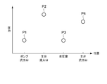
- FIG. 5 shows the flow path internal pressure P1 at the pump inlet and the main valve when the pilot valve is closed when the sub pump is stopped and the main pump is driven in the flow path structure of the first embodiment. It is a graph which shows the relationship between the flow-path internal pressure P2 of an inflow port, the internal pressure P3 of a back pressure chamber, and the flow-path internal pressure P4 of a main valve outflow port.
- FIG. 6 shows the flow path internal pressure P1 at the pump inlet and the main valve when the pilot valve is opened when the sub pump is stopped and the main pump is driven in the flow path structure of the first embodiment.
- FIG. 7 shows the flow path internal pressure P1 at the pump inlet and the main valve when the pilot valve is closed when the main pump is stopped and the sub pump is driven in the flow path structure of the first embodiment. It is a graph which shows the relationship between the flow-path internal pressure P2 of an inflow port, the internal pressure P3 of a back pressure chamber, and the flow-path internal pressure P4 of a main valve outflow port.
- FIG. 8 is a cross-sectional view showing an operation example of the on-off valve when the pilot valve is closed when the main pump is stopped and the sub pump is driven in the flow path structure of the first embodiment.
- FIG. 9 is a block diagram illustrating an outline of a flow path structure in an engine cooling system according to a modification of the first embodiment.
- FIG. 10 is a block diagram showing an outline of the flow path structure of the engine cooling system of the second embodiment.
- FIG. 11 is a cross-sectional view showing a cross-sectional structure around a pilot type on-off valve and a sub-pump in the flow path structure of the second embodiment.
- FIG. 12 is a cross-sectional view showing an operation example of the on-off valve when the pilot valve is opened when the sub pump is stopped and the main pump is driven in the flow path structure of the second embodiment.
- FIG. 13 is a cross-sectional view showing an operation example of the on-off valve when the pilot valve is opened when the main pump is stopped and the sub pump is driven in the flow path structure of the second embodiment.
- the engine cooling system 1 of the present embodiment includes a radiator 10, a thermostat 11, a main pump 14, a sub pump 15, a pilot on-off valve 16, a heater core 17, an ECU (Electronic). Control Unit) 18.
- the sub pump 15 corresponds to a first pump
- the main pump 14 corresponds to a second pump.
- the radiator 10 is connected to the engine 2 via the first flow path W1 and the second flow path W2.
- a heat medium flows inside the engine 2.
- the heat medium absorbs the heat of the engine 2 by flowing inside the engine 2.
- the heat medium that has absorbed the heat of the engine 2 circulates along a path that returns to the engine 2 via the first flow path W1, the radiator 10, and the second flow path W2.
- the radiator 10 cools the heat medium by exchanging heat between the air flowing outside the radiator 10 and the heat medium flowing inside the radiator 10 as the vehicle travels.
- the heater core 17 is connected to the engine 2 via the third flow path W3.
- the heater core 17 corresponds to a device
- the third flow path W3 corresponds to a supply flow path.
- the heater core 17 is connected to the second flow path W2 through the fourth flow path W4.
- the heat medium that has absorbed the heat of the engine 2 circulates along a path that returns to the engine 2 via the third flow path W3, the heater core 17, the fourth flow path W4, and the second flow path W2.
- a connection point between the fourth flow path W4 and the second flow path W2 is indicated by reference numeral C1.
- the heater core 17 is provided in an air passage of a vehicle air conditioner (not shown).
- the air passage is a passage for air blown into the vehicle interior.
- the heater core 17 heats the blown air by exchanging heat between the blown air flowing in the air passage and the heat medium flowing in the heater core 17.
- the main pump 14 is disposed in the middle part between the connection point C1 and the engine 2 in the second flow path W2.
- the main pump 14 is a mechanical pump that is driven based on the power of the engine 2. That is, when the engine 2 is driven, the main pump 14 is also driven, and when the engine 2 is stopped, the main pump 14 is also stopped.
- the main pump 14 circulates the heat medium between the engine 2 and the radiator 10 and between the engine 2 and the heater core 17 based on the drive.
- the thermostat 11 is disposed in the middle portion between the radiator 10 and the connection point C1 in the second flow path W2.
- the thermostat 11 controls the flow of the heat medium with respect to the radiator 10 by opening and closing the second flow path W2. For example, when the temperature of the heat medium is low, such as when the engine 2 is cold started, the thermostat 11 is closed. As a result, the heat medium flows only through the heater core 17 without flowing through the radiator 10, so that the engine 2 can be warmed up early. On the other hand, when the engine 2 is warmed up and the temperature of the heat medium rises, the thermostat 11 is opened. As a result, the heat medium flows through the radiator 10 and is cooled.
- the sub pump 15 is disposed in the middle of the third flow path W3.
- the sub pump 15 is an electric pump that is driven based on electric power supplied from the vehicle battery. That is, the sub pump 15 can be driven regardless of whether the main pump 14 is in a driving state or a stopped state. In other words, the sub pump 15 can be driven independently of the main pump 14.
- the sub pump 15 circulates the heat medium between the engine 2 and the heater core 17 based on the drive.
- the on-off valve 16 is disposed downstream of the sub pump 15 in the third flow path W3.
- the on-off valve 16 controls the flow of the heat medium with respect to the heater core 17 by opening and closing the third flow path W3. Specifically, when the on-off valve 16 is opened, the flow of the heat medium from the engine 2 to the heater core 17 is allowed. On the other hand, when the on-off valve 16 is closed, the flow of the heat medium from the engine 2 to the heater core 17 is blocked.
- the ECU 18 controls the driving of the sub pump 15 and the on-off valve 16. For example, in the case of a hybrid vehicle, if the main pump 14 stops with the stop of the engine 2, the heat medium does not flow through the heater core 17, so that the heater core 17 cannot be heated. In order to avoid this, the ECU 18 drives the sub pump 15 when the engine 2 is stopped to circulate the heat medium between the engine 2 and the heater core 17.
- the ECU 18 closes the on-off valve 16 when the engine 2 is warmed, for example. Thereby, since the circulation of the heat medium between the engine 2 and the heater core 17 is interrupted, the engine 2 can be warmed up early. As a result, fuel consumption can be improved.
- the heater core 17 Even when the cooling device is driven in the maximum cooling state, that is, even when the opening degree of the air mix door is adjusted so that the blown air does not flow through the heater core 17, the heater core 17 The temperature of blowing air will rise with the emitted heat.
- the compressor since the compressor is driven so that the temperature increase of the blown air by the heater core 17 is canceled in order to make the temperature of the blown air follow the set temperature, the compressor power may be deteriorated.
- the ECU 18 of the present embodiment closes the on-off valve 16 when the cooling device is driven. This makes it difficult for heat exchange to be performed between the heater core 17 and the blown air, so that the blown air is hardly heated by the heater core 17. As a result, deterioration of the compressor power of the cooling device can be suppressed.
- a pilot flow path Wp is provided in the third flow path W ⁇ b> 3 so as to communicate the upstream portion of the sub pump 15 and the downstream portion of the on-off valve 16.
- the connection point between the upstream portion of the sub-pump 15 in the third flow path W3 and the pilot flow path Wp is represented by the upstream connection point C2.
- the connection point between the downstream portion of the on-off valve 16 and the pilot flow path Wp in the third flow path W3 is represented by the downstream connection point C3.
- the sub pump 15 is a centrifugal pump. As shown in FIG. 2, the sub pump 15 includes an impeller 150, a rotor 151, and a case 152.
- the impeller 150 and the rotor 151 are fixed to the rotating shaft 153.
- One end of the rotation shaft 153 is supported to be rotatable with respect to the case 152. That is, the impeller 150 and the rotor 151 rotate integrally around the rotation shaft 153.
- the impeller 150 is disposed downstream of the upstream connection point C2 in the third flow path W3. A heat medium flows into the center of the impeller 150 from the upstream connection point C2 of the third flow path W3 through the pump inlet 156.
- the rotor 151 is made of a permanent magnet.
- the case 152 is provided with a stator coil 154 and a substrate 155.
- the stator coil 154 forms a magnetic field for rotating the rotor 151 based on energization.
- a pump outlet 157 is formed in a radially outer portion of the impeller 150 in the case 152.
- the sub pump 15 energizes the stator coil 154 based on a drive signal from the ECU 18. Thereby, a magnetic field is formed by the stator coil 154, an electromagnetic force acts on the rotor 151, and a rotational force is applied to the rotor 151. As a result, the impeller 150 rotates integrally with the rotor 151. Due to the rotation of the impeller 150, the heat medium flowing into the central portion of the impeller 150 from the upstream connection point C2 of the third flow path W3 is discharged from the pump outlet 157 in a state where the pressure is increased.
- the on-off valve 16 is integrated with the sub pump 15.
- the on-off valve 16 includes a main valve 160, a diaphragm 161, and a pilot valve 162.
- the main valve 160 opens and closes the downstream portion of the pump outlet 157 in the third flow path W3.
- a valve housing chamber 163 is formed on the downstream side of the pump outlet 157 in the third flow path W3.
- a main valve 160 is housed in the valve housing chamber 163.
- a main valve inlet 164 communicating with the pump outlet 157 is formed on the side wall of the valve accommodating chamber 163 facing the side surface of the main valve 160.
- a bottom wall of the valve accommodating chamber 163 facing the bottom surface of the main valve 160 is a valve seat 165.
- the valve seat 165 is formed with a main valve outlet 166 that communicates with the downstream connection point C3 of the third flow path W3. That is, the heat medium discharged from the pump outlet 157 flows to the downstream connection point C3 of the third flow path W3 through the main valve inlet 164, the valve storage chamber 163, and the main valve outlet 166.
- the main valve 160 closes the main valve outlet 166 of the valve seat 165 by being seated on the valve seat 165. As a result, the third flow path W3 is closed. That is, the flow of the heat medium from the engine 2 to the heater core 17 is blocked.
- a state where the main valve outlet 166 is closed by the main valve 160 is also referred to as a closed state of the on-off valve 16.
- the main valve 160 opens the main valve outlet 166 of the valve seat 165 by separating from the valve seat 165. Thereby, the 3rd flow path W3 will be in an open state. That is, the flow of the heat medium from the engine 2 to the heater core 17 is allowed.
- the state where the main valve outlet 166 is opened by the main valve 160 is also referred to as the open state of the on-off valve 16.
- the diaphragm 161 is integrally attached to the main valve 160 via the shaft portion 161a.
- the diaphragm 161 is made of a flexible member.
- Diaphragm 161 is disposed between valve accommodating chamber 163 and pilot flow path Wp, in other words, between third flow path W3 and pilot flow path Wp.
- the pilot flow path Wp is provided with a back pressure chamber 167 at a portion where the diaphragm 161 is disposed.
- the back pressure chamber 167 is a portion in which the channel diameter is larger than the other channel portions of the pilot channel Wp.
- the diaphragm 161 is disposed between the back pressure chamber 167 and the third flow path W3.
- a throttle 170 is provided between the upstream connection point C ⁇ b> 2 and the back pressure chamber 167 in the pilot flow path Wp.
- the pilot valve 162 is composed of a solenoid valve. As shown in FIG. 3, the pilot valve 162 includes a valve body 162a and an actuator 162b.
- the actuator 162b is composed of an electromagnetic solenoid. Actuator 162b operates valve body 162a based on energization, and opens and closes a portion on the downstream side of back pressure chamber 167 in pilot flow path Wp.
- a valve seat 168 is provided in the downstream portion of the back pressure chamber 167 in the pilot flow path Wp.
- a through hole 169 communicating with the back pressure chamber 167 is formed in the valve seat 168.
- the closed state of the valve body 162a is also referred to as the closed state of the pilot valve 162
- the opened state of the valve body 162a is also referred to as the opened state of the pilot valve 162.
- the on-off valve 16 of the present embodiment will be described.
- the sub pump 15 when the sub pump 15 is stopped and the main pump 14 is driven, the sub pump 15 acts as a water flow resistance with respect to the heat medium flowing through the third flow path W3. . Therefore, the flow path internal pressure of the pump outlet 157 is lower than the flow path internal pressure of the pump inlet 156.
- the ECU 18 reverses the opening / closing operation of the pilot valve 162 when the sub pump 15 is stopped and the main pump 14 is driven and when the sub pump 15 is driven.
- a high flow path pressure P1 at the pump inlet 156 is applied to the back pressure chamber 167. .
- a pressing force in a direction from the back pressure chamber 167 toward the valve accommodating chamber 163 is applied to the diaphragm 161.
- the diaphragm 161 is elastically deformed in the direction from the back pressure chamber 167 toward the valve accommodating chamber 163, and the on-off valve 16 is closed.
- the respective values of the flow path internal pressure P1 of the pump inlet 156, the flow path internal pressure P2 of the main valve inlet 164, the internal pressure P3 of the back pressure chamber 167, and the flow path internal pressure P4 of the main valve outlet 166 are: As shown in FIG.
- the ECU 18 opens the pilot valve 162 as shown in FIG. 3 when the on-off valve 16 is opened.
- a pressure corresponding to the differential pressure between the flow path internal pressure P1 at the upstream connection point C2 of the third flow path W3 and the flow path internal pressure P4 at the downstream connection point C3 is applied to the back pressure chamber 167.
- the internal pressure P3 of the chamber 167 decreases from the round value shown in FIG. 5 to the triangular value.
- the flow path pressure P2 of the main valve inlet 164 becomes higher than the internal pressure P3 of the back pressure chamber 167, so that a pressing force in the direction from the valve storage chamber 163 toward the back pressure chamber 167 is applied to the diaphragm 161. .
- the diaphragm 161 is elastically deformed in the direction from the valve accommodating chamber 163 toward the back pressure chamber 167, and the on-off valve 16 is opened.
- the flow path internal pressure P2 of the main valve inlet 164 becomes the flow path internal pressure P1 of the pump inlet 156.
- the sub-pump 15 decreases in water flow resistance. Therefore, as shown in FIG. 5, the flow passage pressure P2 at the main valve inlet 164 decreases from a round value to a triangular value.
- the internal pressure P3 of the back pressure chamber 167 increases.
- the internal pressure P3 of the back pressure chamber 167 is higher than the flow path internal pressure P2 of the main valve inlet 164, so that a pressing force in the direction from the back pressure chamber 167 toward the valve storage chamber 163 is applied to the diaphragm 161.
- the diaphragm 161 is elastically deformed in the direction from the back pressure chamber 167 toward the valve accommodating chamber 163, and the on-off valve 16 is closed.
- the ECU 18 closes the pilot valve 162 as shown in FIG.
- the values of the flow path internal pressure P1 of the pump inlet 156, the flow path internal pressure P2 of the main valve inlet 164, the internal pressure P3 of the back pressure chamber 167, and the flow path internal pressure P4 of the main valve outlet 166 are shown in FIG. 7 is indicated by a circle.
- the flow path internal pressure P2 of the main valve flow inlet 164 becomes higher by the discharge pressure of the sub pump 15 than the flow path internal pressure P1 of the pump inlet 156.
- the flow path pressure P1 of the pump inlet 156 is applied to the back pressure chamber 167. Accordingly, the flow path pressure P2 of the main valve inlet 164 is higher than the internal pressure P3 of the back pressure chamber 167, so that a pressing force in the direction from the valve storage chamber 163 toward the back pressure chamber 167 is applied to the diaphragm 161. Due to this pressing force, as shown in FIG. 8, the diaphragm 161 is elastically deformed in the direction from the valve accommodating chamber 163 toward the back pressure chamber 167, and the on-off valve 16 is opened.
- the pilot flow path Wp communicates the upstream and downstream of the portion where the sub pump 15 and the main valve 160 are disposed in the third flow path W3.
- the pilot valve 162 opens and closes a portion downstream of the back pressure chamber 167 in the pilot flow path Wp.
- the main valve 160 opens and closes the third flow path W3 based on the change in the internal pressure P3 of the back pressure chamber 167 accompanying the opening and closing operation of the pilot valve 162.
- the flow path internal pressure of the pump inlet 156 is higher than the flow path internal pressure of the pump outlet 157 due to the water flow resistance of the sub pump 15.
- the valve 162 is closed, the back pressure chamber 167 is applied with the high flow passage pressure P1 of the pump inlet 156.
- the internal pressure of the back pressure chamber 167 when the pilot valve 162 is closed can be increased.
- the internal pressure P3 of the back pressure chamber 167 is the value indicated by the square in FIG. 6, that is, the flow path internal pressure of the main valve inlet 164. It rises only up to the value of P2.
- the internal pressure P3 of the back pressure chamber 167 is the value indicated by a circle in FIG. The pressure rises to a high flow path pressure P1.
- the pressure fluctuation of the back pressure chamber 167 when the pilot valve 162 is closed from the open state becomes “ ⁇ P2” which is larger than “ ⁇ P1” when the sub pump 15 is not present.
- the force applied to the diaphragm 161 can be changed more greatly, in other words, the force applied to the main valve 160 can be changed more greatly, so that the output of the pump 14 is reduced during idle operation or the like. In such a situation, the on-off valve 16 can be closed more appropriately.
- the internal pressure P3 of the back pressure chamber 167 is the flow path of the main valve inlet 164 as shown by a square in FIG. It is the value of the internal pressure P2. Therefore, when the pilot valve 162 is opened from the closed state, the pressure fluctuation in the back pressure chamber 167 becomes “ ⁇ P3”.
- the pilot type on-off valve 16 of the present embodiment when the pilot valve 162 is in the closed state, the high flow passage internal pressure P1 of the pump inlet 156 is applied to the back pressure chamber 167.
- the pressure fluctuation of the back pressure chamber 167 becomes “ ⁇ P4” which is larger than “ ⁇ P3”. Therefore, the on-off valve 16 can be opened more appropriately.
- the on-off valve 16 has a diaphragm 161 disposed between the third flow path W3 and the back pressure chamber 167 and provided integrally with the main valve 160.
- the main valve 160 can be easily opened and closed based on the change in the internal pressure P3 of the back pressure chamber 167 accompanying the opening and closing operation of the pilot valve 162.
- the pilot valve 162 performs the opening / closing operation in reverse when the sub pump 15 is stopped and the main pump 14 is driven and when the sub pump 15 is driven. Thereby, the on-off valve 16 can be opened and closed appropriately.
- the sub pump 15 is disposed upstream of the main valve 160.
- the pilot flow path Wp communicates the upstream portion of the sub-pump 15 and the downstream portion of the main valve 160 in the third flow path W3 with the back pressure chamber 167.
- the main valve 160 can be opened using the discharge pressure of the sub pump 15 when the sub pump 15 is driven. Therefore, the configuration of the present embodiment is effective for a flow path structure that uses the on-off valve 16 in the open state when the sub pump 15 is driven.
- the on-off valve 16 is integrated with the sub pump 15. This eliminates the need for a separate pipe for connecting the sub-pump 15 and the on-off valve 16, thereby reducing the size of the flow path structure of the engine cooling system 1.
- the on-off valve 16 Since the on-off valve 16 has a pilot-type structure, the size of the drive unit can be reduced as compared with the case where a coil-driven direct acting valve is used. In addition, the power consumption of the on-off valve 16 is only necessary for closing the pilot valve 162 so as to close the pilot flow path Wp, so that the power consumption is reduced compared to the coil-driven direct acting valve. You can also The reason for closing the on-off valve 16 is to improve fuel efficiency by improving the warmth of the engine 2 and to reduce the compressor power of the cooling device. Therefore, the effect of reducing the power consumption when the on-off valve 16 is closed is as follows. large.
- a three-way valve 19 is provided in the middle part between the engine 2 and the sub pump 15 in the third flow path W ⁇ b> 3.
- the three-way valve 19 is connected to the fourth flow path W4 via the fifth flow path W5.
- the three-way valve 19 has a state in which the heat medium flowing out from the engine 2 to the third flow path W3 flows to the heater core 17 and a fourth flow without directing the heat medium flowing out from the engine 2 to the third flow path W3 toward the heater core 17.
- the state flowing through the road W4 can be switched.
- the operation of the three-way valve 19 is controlled by the ECU 18.
- a heat source device 3 for a vehicle different from the engine 2 is disposed in the sixth flow path W6.
- the heat source device 3 is, for example, an inverter or an electric heater mounted on a vehicle.
- the electric heater is a device that generates heat based on the supply of electric power from a vehicle-mounted battery.
- the main pump 14 drives to drive the engine 2 and the radiator 10, and the engine 2.
- the heater core 17 circulate between the heat medium. That is, the heat medium circuit on the radiator 10 side and the heat medium circuit on the heater core 17 side are integrated.
- the heat medium circulates between the engine 2 and the radiator 10 by driving the main pump 14.
- the ECU 18 drives the sub pump 15 in this state, the heat medium circulates between the heat source device 3 and the heater core 17. That is, the heat medium circuit on the radiator 10 side and the heat medium circuit on the heater core 17 side can be separated.
- the on-off valve 16 is arranged on the upstream side of the sub pump 15 in the third flow path W3.
- the midway portion between the on-off valve 16 and the sub pump 15 in the third flow path W3 is connected to the fourth flow path W4 via the sixth flow path W6.
- a heat source device 3 for a vehicle different from the engine 2 is disposed in the sixth flow path W6.
- the heat medium circulates between the engine 2 and the radiator 10 and between the engine 2 and the heater core 17 by driving the main pump 14. To do.
- the heat medium circulates between the engine 2 and the radiator 10 by driving the main pump 14.
- the heat medium circulates between the heat source device 3 and the heater core 17 by driving the sub pump 15.
- the on-off valve 16 of this embodiment has the function of the three-way valve 19 of the modification of the first embodiment.
- the main valve inlet 164 of the on-off valve 16 communicates with the upstream connection point C2 in the third flow path W3.
- a main valve outlet 166 of the on-off valve 16 communicates with an inlet 156 of the sub pump 15.
- the outlet 157 of the sub pump 15 communicates with the downstream connection point C3 in the third flow path W3.
- the pilot flow path Wp is provided so as to communicate the upstream portion of the on-off valve 16 and the downstream portion of the sub pump 15 in the third flow path W3.
- the on-off valve 16 of the present embodiment For example, if the pilot valve 162 is closed while the sub pump 15 is stopped and the main pump 14 is being driven, the internal pressure of the flow path at the main valve inlet 164 is applied to the back pressure chamber 167. Thereby, a pressing force in a direction from the back pressure chamber 167 toward the valve accommodating chamber 163 is applied to the diaphragm 161. With this pressing force, as shown in FIG. 11, the diaphragm 161 is elastically deformed in the direction from the back pressure chamber 167 toward the valve accommodating chamber 163, and the on-off valve 16 is in a closed state.
- the ECU 18 opens the pilot valve 162 as shown in FIG. 12 when the on-off valve 16 is opened.
- voltage of the flow path internal pressure of the main valve inflow port 164 and the flow path internal pressure of the pump outflow port 157 is added to the back pressure chamber 167, the internal pressure of the back pressure chamber 167 falls. Therefore, since the internal pressure of the main valve inflow port 164 is higher than the internal pressure of the back pressure chamber 167, a pressing force in the direction from the valve storage chamber 163 toward the back pressure chamber 167 is applied to the diaphragm 161. By this pressing force, the diaphragm 161 is elastically deformed in the direction from the valve accommodating chamber 163 toward the back pressure chamber 167, and the on-off valve 16 is opened.
- the ECU 18 opens the pilot valve 162 as shown in FIG.
- a pressure corresponding to a differential pressure between the internal pressure of the main valve inlet 164 and the internal pressure of the pump outlet 157 is applied to the back pressure chamber 167.
- the internal pressure of the flow path of the pump outlet 157 is increased by the amount corresponding to the discharge pressure of the sub pump 15, and as a result, the internal pressure of the back pressure chamber 167 is higher than the internal pressure of the flow path of the main valve inlet 164. . Therefore, a pressing force in a direction from the back pressure chamber 167 toward the valve accommodating chamber 163 is applied to the diaphragm 161.
- the diaphragm 161 is elastically deformed in the direction from the valve accommodating chamber 163 toward the back pressure chamber 167, and the on-off valve 16 is closed.
- the back pressure chamber 167 is subjected to a pressure corresponding to the differential pressure between the flow path internal pressure of the main valve inlet 164 and the flow path internal pressure of the pump outlet 157.
- the flow path internal pressure of the pump outlet 157 is low due to the water flow resistance of the sub pump 15, and therefore, when the pilot valve 162 is opened compared to the case where the sub pump 15 does not exist.
- the internal pressure of the back pressure chamber 167 can be lowered. Therefore, the pressure fluctuation of the back pressure chamber 167 when the pilot valve 162 is opened from the closed state can be further increased.
- the force applied to the diaphragm 161 can be increased, in other words, the force applied to the main valve 160 can be increased, so that the output of the pump 14 decreases during idle operation or the like. Therefore, the opening / closing valve 16 can be opened more appropriately. Similarly, the on-off valve 16 can be closed more appropriately.
- the sub pump 15 is disposed on the downstream side with respect to the main valve 160.
- the pilot flow path Wp communicates the upstream portion of the sub-pump 15 and the downstream portion of the main valve 160 in the third flow path W3 with the back pressure chamber 167.
- the main valve 160 can be closed using the discharge pressure of the sub pump 15 when the sub pump 15 is driven. Therefore, the configuration of the above embodiment is effective for the flow path structure that uses the on-off valve 16 in the closed state when the sub pump 15 is driven.
- each embodiment can also be implemented with the following forms.
- the on-off valve 16 of each embodiment is not limited to the one using the diaphragm 161, but may be any one that has a configuration that opens and closes the main valve 160 based on a change in the internal pressure of the back pressure chamber 167.
- the pilot valve 162 of each embodiment is not limited to a solenoid valve, and may be a motor driven valve.
- the on-off valve 16 of each embodiment may be used as a flow rate adjusting valve that adjusts the flow rate of the heat medium by adjusting the opening degree of the main valve 160.
- the main heat source device for heating the heat medium in each embodiment is not limited to the engine 2 and may be an inverter, an electric heater, or the like.
- the flow path structure of the engine cooling system 1 of each embodiment is not limited to the flow path structure of the heat exchange cycle of the engine 2, and can be applied to the flow path structures of various cold / hot water systems such as a refrigeration cycle. Moreover, you may change suitably the apparatus by which the flow of a heat medium is controlled by the opening / closing operation
- This kind of cold / hot water system equipment includes a heat exchanger for cooling or heating the oil of an automatic transmission, a heat exchanger for cooling a motor generator, an EGR cooler, and a vehicle battery for cooling or heating. There are heat exchangers, intercoolers for supercharging, radiators, cooler cores, etc. Further, a fluid other than the heat medium may be used in accordance with the configuration of the flow path structure.
- the main pump 14 of each embodiment is not limited to a mechanical pump that is driven based on the power of the engine 2, but may be an electric pump that is driven based on the power of the on-vehicle battery.
Landscapes
- Engineering & Computer Science (AREA)
- General Engineering & Computer Science (AREA)
- Mechanical Engineering (AREA)
- Chemical & Material Sciences (AREA)
- Combustion & Propulsion (AREA)
- Fluid-Driven Valves (AREA)
- Air-Conditioning For Vehicles (AREA)
Abstract
流路構造は、供給流路(W3)を介して機器(17)に流体を供給するポンプ(15)と、前記供給流路に設けられるパイロット式の開閉弁(16)と、を備える。前記開閉弁は、前記供給流路に配置される主弁(160)と、前記供給流路における前記ポンプ及び前記主弁が配置される部分の上流及び下流を連通させるとともに、背圧室(167)が設けられるパイロット流路(Wp)と、前記パイロット流路における前記背圧室よりも下流側の部分を開閉させるパイロット弁(162)と、を有する。前記主弁は、前記パイロット弁の開閉動作に伴う前記背圧室の内部圧力の変化に基づいて前記供給流路を開閉する。
Description
本出願は、2015年10月29日に出願された日本国特許出願2015-213161号に基づくものであって、その優先権の利益を主張するものであり、その特許出願の全ての内容が、参照により本明細書に組み込まれる。
本開示は、パイロット式の開閉弁を備える流路構造に関する。
従来、この種の流路構造としては、特許文献1に記載の流路構造がある。特許文献1に記載の流路構造では、流路の途中にパイロット式の開閉弁が配置されている。開閉弁は、ボディと、ダイヤフラム弁と、パイロット弁と、電磁ソレノイドとを備えている。ボディには、流入通路と、流出通路と、連通路と、パイロット通路とが形成されている。ダイヤフラム弁は、ボディの流入通路と流出通路との間に介在して通路を開閉する。連通路は、ダイヤフラム弁の背圧室と流入通路とを連通させる。パイロット通路は、ダイヤフラム弁の背圧室と流出通路とを連通させる。パイロット弁は、パイロット通路を開閉する。電磁ソレノイドは、パイロット弁を開閉動作させる。
特許文献1に記載の開閉弁では、パイロット弁が閉弁状態になると、流入通路内の水が連通路を通じてダイヤフラムの背圧室に流入する。これにより、流入通路側の水圧がダイヤフラム弁の背圧室に作用してダイヤフラム弁が閉弁し、開閉弁が閉弁状態になる。
また、特許文献1に記載の開閉弁では、パイロット弁が開弁状態になると、背圧室内の水がパイロット通路を通じて流出通路へと流れる。これにより、ダイヤフラム弁の背圧室の内圧が低下してダイヤフラム弁が開弁し、開閉弁が開弁状態になる。
車両のエンジン冷却システムでは、エンジンの動力に基づき駆動する機械式のポンプにより、エンジンを冷却する熱媒体をラジエータやヒータコア等に循環させている。このようなエンジン冷却システムにおいて、特許文献1に記載のパイロット式の開閉弁を熱媒体の流路に配置した場合、開閉弁の閉弁動作が適切に行われない可能性がある。詳しくは以下の通りである。
エンジンの回転速度は走行負荷に応じて変動するため、それに連動してポンプの出力も変動する。例えばエンジン回転速度の遅いアイドル運転時には、エンジンは低負荷状態となっている。エンジンが低負荷状態である場合、ポンプの出力が低下するため、開閉弁に供給される熱媒体の圧力も低下する。特許文献1に記載の開閉弁では、パイロット弁が閉弁動作する際の背圧室の圧力変動により、ダイヤフラム弁が閉弁する。開閉弁に供給される熱媒体の圧力が低下すると、背圧室の圧力変動が小さくなるため、結果的にダイヤフラム弁の閉弁動作が適切に行われない可能性がある。同様の課題は、ダイヤフラム弁が開弁動作する際にも生じ得る。
本開示の目的は、より適切にパイロット式の開閉弁を開閉動作させることのできる流路構造を提供することにある。
本開示の一態様による流路構造は、供給流路を介して機器に流体を供給するポンプと、供給流路に設けられるパイロット式の開閉弁と、を備える。開閉弁は、供給流路に配置される主弁と、供給流路におけるポンプ及び主弁が配置される部分の上流及び下流を連通させるとともに、背圧室が設けられるパイロット流路と、パイロット流路における背圧室よりも下流側の部分を開閉させるパイロット弁と、を有する。主弁は、パイロット弁の開閉動作に伴う背圧室の内部圧力の変化に基づいて供給流路を開閉する。
この構成によれば、パイロット弁が開弁している場合、背圧室には、供給流路におけるポンプ及び主弁が配置される部分の上流部分の流路内圧と、その下流部分の流路内圧との差圧に応じた圧力が加わる。また、ポンプが停止している場合、ポンプが通水抵抗として作用するため、ポンプ流入口の流路内圧が高圧となり、ポンプ流出口の流路内圧が低圧となる。したがって、ポンプが存在しない場合と比較すると、パイロット弁が開弁している際の背圧室の内部圧力を、ポンプの通水抵抗の分だけ、より低下させることができる。これにより、パイロット弁が開弁状態から閉弁動作する際、及びパイロット弁が閉弁状態から開弁動作する際の背圧室の圧力変動がより大きくなる。結果的に、主弁に加わる力をより大きく変動させることができるため、より適切に開閉弁を開閉動作させることができる。
<第1実施形態>
以下、車両のエンジン冷却システムの流路構造の第1実施形態について説明する。はじめに、エンジン冷却システムの概要について説明する。
以下、車両のエンジン冷却システムの流路構造の第1実施形態について説明する。はじめに、エンジン冷却システムの概要について説明する。
図1に示されるように、本実施形態のエンジン冷却システム1は、ラジエータ10と、サーモスタット11と、メインポンプ14と、サブポンプ15と、パイロット式の開閉弁16と、ヒータコア17と、ECU(Electronic Control Unit)18とを備えている。本実施形態では、サブポンプ15が第1ポンプに相当し、メインポンプ14が第2ポンプに相当する。
ラジエータ10は、第1流路W1及び第2流路W2を介してエンジン2に接続されている。エンジン2の内部には熱媒体が流れている。熱媒体は、エンジン2の内部を流れることで、エンジン2の熱を吸熱する。エンジン2の熱を吸熱した熱媒体は、第1流路W1、ラジエータ10、及び第2流路W2を経てエンジン2に戻る経路を循環する。ラジエータ10は、車両の走行に伴いラジエータ10の外部を流れる空気と、ラジエータ10の内部を流れる熱媒体との間で熱交換を行うことにより熱媒体を冷却する。
ヒータコア17は、第3流路W3を介してエンジン2に接続されている。本実施形態では、ヒータコア17が機器に相当し、第3流路W3が供給流路に相当する。また、ヒータコア17は、第4流路W4を介して第2流路W2に接続されている。これにより、エンジン2の熱を吸熱した熱媒体は、第3流路W3、ヒータコア17、第4流路W4、及び第2流路W2を経てエンジン2に戻る経路を循環する。図中には、第4流路W4と第2流路W2との接続点を符号C1で示している。ヒータコア17は、図示しない車両の空調装置の空気通路内に設けられている。空気通路は、車室内に送風される空気の通路である。ヒータコア17は、空気通路内を流れる送風空気と、ヒータコア17の内部を流れる熱媒体との間で熱交換を行うことにより、送風空気を加熱する。
メインポンプ14は、第2流路W2における接続点C1とエンジン2との間の途中部分に配置されている。メインポンプ14は、エンジン2の動力に基づき駆動する機械式のポンプである。すなわち、エンジン2が駆動するとメインポンプ14も駆動し、エンジン2が停止するとメインポンプ14も停止する。メインポンプ14は、その駆動に基づき熱媒体をエンジン2とラジエータ10との間、及びエンジン2とヒータコア17との間で循環させる。
サーモスタット11は、第2流路W2におけるラジエータ10と接続点C1との間の途中部分に配置されている。サーモスタット11は、第2流路W2を開閉させることにより、ラジエータ10に対する熱媒体の流れを制御する。例えばエンジン2の冷間始動時等、熱媒体の温度が低い状況では、サーモスタット11が閉状態になる。これにより、熱媒体がラジエータ10を流れずにヒータコア17だけを流れるため、エンジン2の早期の暖気が可能になる。これに対し、エンジン2が暖気されて熱媒体の温度が上昇すると、サーモスタット11が開状態になる。これにより、熱媒体がラジエータ10を流れて冷却されるようになる。
サブポンプ15は、第3流路W3の途中に配置されている。サブポンプ15は、車載バッテリから供給される電力に基づき駆動する電動ポンプである。すなわち、サブポンプ15は、メインポンプ14が駆動状態及び停止状態のいずれであるかに関わらず駆動することができる。換言すれば、サブポンプ15は、メインポンプ14と独立して駆動することができる。サブポンプ15は、その駆動に基づき熱媒体をエンジン2とヒータコア17との間で循環させる。
開閉弁16は、第3流路W3におけるサブポンプ15の下流側に配置されている。開閉弁16は、第3流路W3を開閉することによりヒータコア17に対する熱媒体の流れを制御する。詳しくは、開閉弁16が開弁状態になると、エンジン2からヒータコア17への熱媒体の流れが許容される。これに対し、開閉弁16が閉弁状態になると、エンジン2からヒータコア17への熱媒体の流れが遮断される。
ECU18は、サブポンプ15及び開閉弁16の駆動を制御する。例えばハイブリッド車両の場合、エンジン2の停止に伴いメインポンプ14が停止すると、ヒータコア17に熱媒体が流れなくなるため、ヒータコア17を加熱することができなくなる。これを回避するために、ECU18は、エンジン2の停止時にサブポンプ15を駆動させることにより、エンジン2とヒータコア17との間で熱媒体を循環させる。
また、ECU18は、例えばエンジン2の暖気時に開閉弁16を閉弁状態にする。これにより、エンジン2とヒータコア17との間での熱媒体の循環が遮断されるため、エンジン2を早期に暖気させることができる。その結果、燃費を改善することができる。
一方、空調装置では、その冷房装置が最大冷房の状態で駆動している場合でも、すなわち送風空気がヒータコア17を流れないようにエアミックスドアの開度が調整されている場合でも、ヒータコア17から発せられる熱により送風空気の温度が上昇してしまう。この場合、冷房装置では、送風空気の温度を設定温度に追従させるべく、ヒータコア17による送風空気の温度上昇分が打ち消されるようにコンプレッサが駆動するため、コンプレッサ動力が悪化するおそれがある。これを解消するために、本実施形態のECU18は、冷房装置が駆動している場合には開閉弁16を閉弁状態にする。これにより、ヒータコア17と送風空気との間で熱交換が行われ難くなるため、ヒータコア17により送風空気が加熱され難くなる。結果的に、冷房装置のコンプレッサ動力の悪化を抑制することができる。
次に、サブポンプ15及び開閉弁16の構造について詳しく説明する。
図1に示されるように、第3流路W3には、サブポンプ15の上流部分と開閉弁16の下流部分とを連通するようにパイロット流路Wpが設けられている。以下では、第3流路W3におけるサブポンプ15の上流部分とパイロット流路Wpとの接続点を上流側接続点C2で表す。また、第3流路W3における開閉弁16の下流部分とパイロット流路Wpとの接続点を下流側接続点C3で表す。
図1に示されるように、第3流路W3には、サブポンプ15の上流部分と開閉弁16の下流部分とを連通するようにパイロット流路Wpが設けられている。以下では、第3流路W3におけるサブポンプ15の上流部分とパイロット流路Wpとの接続点を上流側接続点C2で表す。また、第3流路W3における開閉弁16の下流部分とパイロット流路Wpとの接続点を下流側接続点C3で表す。
サブポンプ15は、遠心ポンプである。図2に示されるように、サブポンプ15は、インペラ150と、ロータ151と、ケース152とを備えている。
インペラ150及びロータ151は、回転軸153に固定されている。回転軸153の一端部は、ケース152に対して回転可能に支持されている。すなわち、インペラ150及びロータ151は、回転軸153を中心に一体的に回転する。インペラ150は、第3流路W3における上流側接続点C2の下流側に配置されている。インペラ150の中心部には、第3流路W3の上流側接続点C2からポンプ流入口156を介して熱媒体が流入する。
ロータ151は、永久磁石からなる。
ロータ151は、永久磁石からなる。
ケース152には、ステータコイル154と、基板155とが設けられている。ステータコイル154は、通電に基づいて、ロータ151を回転させるための磁界を形成する。
基板155には、サブポンプ15を駆動させるための駆動回路等の各種回路が実装されている。ケース152におけるインペラ150の径方向外側の部分には、ポンプ流出口157が形成されている。
サブポンプ15では、ECU18からの駆動信号に基づきステータコイル154に対する通電が行われる。これにより、ステータコイル154により磁界が形成されてロータ151に電磁力が作用し、ロータ151に回転力が付与される。その結果、インペラ150がロータ151と一体となって回転する。インペラ150の回転により、第3流路W3の上流側接続点C2からインペラ150の中心部に流入した熱媒体が、圧力の高められた状態でポンプ流出口157から吐出される。
図3に示されるように、開閉弁16は、サブポンプ15と一体化されている。開閉弁16は、主弁160と、ダイヤフラム161と、パイロット弁162とを備えている。
主弁160は、第3流路W3におけるポンプ流出口157の下流側部分を開閉する。詳しくは、第3流路W3におけるポンプ流出口157の下流側には、弁収容室163が形成されている。弁収容室163には、主弁160が収容されている。主弁160の側面に対向する弁収容室163の側壁には、ポンプ流出口157に連通される主弁流入口164が形成されている。主弁160の底面に対向する弁収容室163の底壁は、弁座165となっている。弁座165には、第3流路W3の下流側接続点C3に連通される主弁流出口166が貫通して形成されている。すなわち、ポンプ流出口157から吐出される熱媒体は、主弁流入口164、弁収容室163、及び主弁流出口166を通じて第3流路W3の下流側接続点C3へと流れる。
主弁160は、弁座165に着座することにより、弁座165の主弁流出口166を閉塞する。これにより、第3流路W3が閉状態になる。すなわち、エンジン2からヒータコア17への熱媒体の流れが遮断される。以下では、主弁160により主弁流出口166が閉塞されている状態を、開閉弁16の閉状態とも称する。
主弁160は、弁座165から離座することにより、弁座165の主弁流出口166を開放する。これにより、第3流路W3が開状態になる。すなわち、エンジン2からヒータコア17への熱媒体の流れが許容される。以下では、主弁160により主弁流出口166が開放されている状態を、開閉弁16の開状態とも称する。
ダイヤフラム161は、軸部161aを介して主弁160に一体的に取り付けられている。ダイヤフラム161は、可撓性を有する部材からなる。ダイヤフラム161は、弁収容室163とパイロット流路Wpとの間、換言すれば第3流路W3とパイロット流路Wpとの間に配置されている。より詳しくは、パイロット流路Wpには、ダイヤフラム161の配置される部分に背圧室167が設けられている。背圧室167は、パイロット流路Wpの他の流路部分よりも流路径が拡大された部分である。ダイヤフラム161は、この背圧室167と第3流路W3との間に配置されている。図1に示されるように、パイロット流路Wpにおける上流側接続点C2と背圧室167との間には絞り170が設けられている。
パイロット弁162は、電磁弁からなる。図3に示されるように、パイロット弁162は、弁体162aと、アクチュエータ162bとを備えている。アクチュエータ162bは、電磁ソレノイドからなる。アクチュエータ162bは、通電に基づき弁体162aを動作させ、パイロット流路Wpにおける背圧室167よりも下流側の部分を開閉する。
詳しくは、パイロット流路Wpにおける背圧室167の下流側の部分には、弁座168が設けられている。弁座168には、背圧室167に連通される貫通孔169が形成されている。アクチュエータ162bの駆動により弁体162aが弁座168に着座すると、貫通孔169が閉塞される。これにより、パイロット流路Wpが閉状態になり、背圧室167から第3流路W3への熱媒体の流れが遮断される。
アクチュエータ162bの駆動により弁体162aが弁座168から離座すると、貫通孔169が開放される。これにより、パイロット流路Wpが開状態になるため、熱媒体が第3流路W3の上流側接続点C2から背圧室167を介して下流側接続点C3へと流れることが可能となる。
以下では、弁体162aの閉弁状態をパイロット弁162の閉弁状態とも称し、弁体162aの開弁状態をパイロット弁162の開弁状態とも称する。
次に、本実施形態の開閉弁16の動作例について説明する。
本実施形態のエンジン冷却システム1では、サブポンプ15が停止し、且つメインポンプ14が駆動している場合には、第3流路W3を流れる熱媒体に対してサブポンプ15が通水抵抗として作用する。よって、ポンプ流入口156の流路内圧よりも、ポンプ流出口157の流路内圧の方が低くなる。
本実施形態のエンジン冷却システム1では、サブポンプ15が停止し、且つメインポンプ14が駆動している場合には、第3流路W3を流れる熱媒体に対してサブポンプ15が通水抵抗として作用する。よって、ポンプ流入口156の流路内圧よりも、ポンプ流出口157の流路内圧の方が低くなる。
これに対し、メインポンプ14が停止し、且つサブポンプ15が駆動している場合には、サブポンプ15の吐出圧により、ポンプ流入口156の流路内圧よりも、ポンプ流出口157の流路内圧の方が高くなる。
以上を考慮し、ECU18は、サブポンプ15が停止し、且つメインポンプ14が駆動している場合と、サブポンプ15が駆動している場合とで、パイロット弁162の開閉動作を逆転させる。
詳しくは、サブポンプ15が停止し、且つメインポンプ14が駆動している状況において仮にパイロット弁162が閉弁状態である場合、ポンプ流入口156の高圧の流路内圧P1が背圧室167に加わる。これにより、背圧室167から弁収容室163に向かう方向の押圧力がダイヤフラム161に加わる。この押圧力により、図4に示されるように、ダイヤフラム161が背圧室167から弁収容室163に向かう方向に弾性変形し、開閉弁16が閉弁状態になる。この状況では、ポンプ流入口156の流路内圧P1、主弁流入口164の流路内圧P2、背圧室167の内部圧力P3、及び主弁流出口166の流路内圧P4のそれぞれの値は図5に丸で示されるようになる。
このように開閉弁16が閉弁している状況において、ECU18は、開閉弁16を開弁させる場合には、図3に示されるように、パイロット弁162を開弁させる。これにより、第3流路W3の上流側接続点C2の流路内圧P1と、下流側接続点C3の流路内圧P4との差圧に応じた圧力が背圧室167に加わるため、背圧室167の内部圧力P3は、図5に示される丸の値から三角の値へと低下する。これにより、背圧室167の内部圧力P3よりも主弁流入口164の流路内圧P2の方が高くなるため、弁収容室163から背圧室167に向かう方向の押圧力がダイヤフラム161に加わる。この押圧力により、図3に示されるように、ダイヤフラム161が弁収容室163から背圧室167に向かう方向に弾性変形し、開閉弁16が開弁状態になる。
また、開閉弁16が開弁状態になることにより、熱媒体が第3流路W3を流れるようになると、主弁流入口164の流路内圧P2が、ポンプ流入口156の流路内圧P1に対して、サブポンプ15の通水抵抗の分だけ低下する。そのため、図5に示されるように、主弁流入口164の流路内圧P2は丸の値から三角の値へと低下する。
開閉弁16が開弁状態である場合、ポンプ流入口156の流路内圧P1、主弁流入口164の流路内圧P2、背圧室167の内部圧力P3、及び主弁流出口166の流路内圧P4のそれぞれの値は図6に三角で示されるようになる。このように開閉弁16が開弁している状況において、ECU18は、開閉弁16を閉弁させる際には、図4に示されるように、パイロット弁162を閉弁させる。これにより、ポンプ流入口156の高圧の流路内圧P1が背圧室167に加わるため、背圧室167の内部圧力P3は、図6に示される三角の値から丸の値へと変化する。すなわち、背圧室167の内部圧力P3が上昇する。これにより、主弁流入口164の流路内圧P2よりも背圧室167の内部圧力P3の方が高くなるため、背圧室167から弁収容室163に向かう方向の押圧力がダイヤフラム161に加わる。この押圧力により、図4に示されるように、ダイヤフラム161が背圧室167から弁収容室163に向かう方向に弾性変形し、開閉弁16が閉弁状態になる。
一方、ECU18は、メインポンプ14が停止している状況でサブポンプ15を駆動させる場合には、図8に示されるように、パイロット弁162を閉弁させる。この場合、ポンプ流入口156の流路内圧P1、主弁流入口164の流路内圧P2、背圧室167の内部圧力P3、及び主弁流出口166の流路内圧P4のそれぞれの値は図7に丸で示されるようになる。すなわち、ポンプ流入口156の流路内圧P1よりも主弁流入口164の流路内圧P2の方が、サブポンプ15の吐出圧の分だけ高くなる。また、パイロット弁162が閉弁されている場合、ポンプ流入口156の流路内圧P1が背圧室167に加わる。したがって、背圧室167の内部圧力P3よりも主弁流入口164の流路内圧P2の方が高くなるため、弁収容室163から背圧室167に向かう方向の押圧力がダイヤフラム161に加わる。この押圧力により、図8に示されるように、ダイヤフラム161が弁収容室163から背圧室167に向かう方向に弾性変形し、開閉弁16が開弁状態になる。
以上説明した本実施形態のエンジン冷却システム1の流路構造によれば、以下の(1)~(6)に示される作用及び効果を得ることができる。
(1)パイロット流路Wpは、第3流路W3におけるサブポンプ15及び主弁160が配置される部分の上流及び下流を連通させている。パイロット弁162は、パイロット流路Wpにおける背圧室167よりも下流側の部分を開閉する。主弁160は、パイロット弁162の開閉動作に伴う背圧室167の内部圧力P3の変化に基づいて第3流路W3を開閉する。
このような構成によれば、サブポンプ15が停止している場合、サブポンプ15の通水抵抗によりポンプ流出口157の流路内圧よりもポンプ流入口156の流路内圧の方が高いため、パイロット弁162が閉弁した際、背圧室167には、ポンプ流入口156の高圧の流路内圧P1が加わる。これにより、サブポンプ15が存在しない場合と比較すると、パイロット弁162が閉弁する際の背圧室167の内部圧力を高めることができる。
詳しくは、仮にサブポンプ15が存在しないとすると、パイロット弁162が閉弁した際、背圧室167の内部圧力P3は、図6に四角で示される値、すなわち主弁流入口164の流路内圧P2の値までしか上昇しない。これに対し、本実施形態のパイロット式の開閉弁16では、パイロット弁162が閉弁した際、背圧室167の内部圧力P3が、図6に丸で示される値、すなわちポンプ流入口156の高圧の流路内圧P1まで上昇する。これにより、サブポンプ15が存在しない場合と比較すると、パイロット弁162が閉弁する際の背圧室167の内部圧力P3を高めることができる。その結果、パイロット弁162が開弁状態から閉弁動作する際の背圧室167の圧力変動が、サブポンプ15が存在しない場合の「ΔP1」よりも大きい「ΔP2」となる。結果的に、ダイヤフラム161に加わる力をより大きく変動させることができる、換言すれば主弁160に加わる力をより大きく変動させることができるため、アイドル運転時等、ポンプ14の出力が低下するような状況において、より適切に開閉弁16を閉弁動作させることができる。
また、仮にサブポンプ15が存在しないとすると、パイロット弁162が閉弁状態であるとき、背圧室167の内部圧力P3は、図5に四角で示されるように、主弁流入口164の流路内圧P2の値となっている。そのため、パイロット弁162が閉弁状態から開弁動作する際に、背圧室167の圧力変動は「ΔP3」となる。これに対し、本実施形態のパイロット式の開閉弁16では、パイロット弁162が閉弁状態であるとき、ポンプ流入口156の高圧の流路内圧P1が背圧室167に加わっているため、パイロット弁162が閉弁状態から開弁動作した際に、背圧室167の圧力変動が「ΔP3」よりも大きい「ΔP4」となる。そのため、より適切に開閉弁16を開弁動作させることもできる。
(2)開閉弁16は、第3流路W3と背圧室167との間に配置されて主弁160に一体的に設けられるダイヤフラム161を有している。これにより、パイロット弁162の開閉動作に伴う背圧室167の内部圧力P3の変化に基づいて、主弁160を容易に開閉動作させることができる。
(3)パイロット弁162は、サブポンプ15が停止し、且つメインポンプ14が駆動している場合と、サブポンプ15が駆動している場合とで、開閉動作を逆に行う。これにより、開閉弁16を適切に開閉させることができる。
(4)サブポンプ15は、主弁160に対して上流側に配置されている。また、パイロット流路Wpは、第3流路W3におけるサブポンプ15の上流部分、及び主弁160の下流部分を背圧室167に連通させている。これにより、サブポンプ15の駆動時にサブポンプ15の吐出圧を利用して主弁160を開弁させることができる。よって、上記本実施形態の構成は、サブポンプ15の駆動時に開閉弁16を開弁状態で用いる流路構造に対して有効である。
(5)開閉弁16は、サブポンプ15と一体化されている。これにより、サブポンプ15と開閉弁16とを接続する別の流路配管が不要なため、エンジン冷却システム1の流路構造を小型化することができる。
(6)開閉弁16がパイロット式の構造からなるため、コイル駆動式の直動弁を用いる場合と比較すると、駆動部の大きさを小さくすることができる。また、開閉弁16の消費電力は、パイロット流路Wpを塞ぐようにパイロット弁162を閉弁させるために必要な電力だけでよいため、コイル駆動式の直動弁と比較すると、消費電力を低減することもできる。開閉弁16を閉弁させる理由が、エンジン2の暖気性の向上による燃費改善や冷房装置のコンプレッサ動力の低減であるため、開閉弁16を閉弁させる際の消費電力を低減することによる効果は大きい。
(変形例)
次に、第1実施形態のエンジン冷却システム1の流路構造の変形例について説明する。
図9に示されるように、この変形例では、第3流路W3におけるエンジン2とサブポンプ15との間の途中部分に、三方弁19が設けられている。三方弁19は、第5流路W5を介して第4流路W4に接続されている。三方弁19は、エンジン2から第3流路W3に流出した熱媒体をヒータコア17に流す状態と、エンジン2から第3流路W3に流出した熱媒体をヒータコア17に向かわせずに第4流路W4に流す状態とを切り替えることができる。三方弁19の動作はECU18により制御される。
次に、第1実施形態のエンジン冷却システム1の流路構造の変形例について説明する。
図9に示されるように、この変形例では、第3流路W3におけるエンジン2とサブポンプ15との間の途中部分に、三方弁19が設けられている。三方弁19は、第5流路W5を介して第4流路W4に接続されている。三方弁19は、エンジン2から第3流路W3に流出した熱媒体をヒータコア17に流す状態と、エンジン2から第3流路W3に流出した熱媒体をヒータコア17に向かわせずに第4流路W4に流す状態とを切り替えることができる。三方弁19の動作はECU18により制御される。
また、第3流路W3における三方弁19とサブポンプ15との間の途中部分は、第6流路W6を介して第4流路W4に接続されている。第6流路W6には、エンジン2とは別の車両の熱源機器3が配置されている。熱源機器3は、例えば車両に搭載されるインバータや電気ヒータである。電気ヒータは、車載バッテリからの電力の供給に基づき発熱する機器である。
このエンジン冷却システム1では、ECU18が、エンジン2からヒータコア17に熱媒体が流れる状態に三方弁19を切り替えている場合、メインポンプ14の駆動により、エンジン2とラジエータ10との間、及びエンジン2とヒータコア17との間を熱媒体が循環する。すなわち、ラジエータ10側の熱媒体循環回路と、ヒータコア17側の熱媒体循環回路とが一体となっている。
また、ECU18が、エンジン2から第4流路W4に熱媒体が流れる状態に三方弁19を切り替えている場合、メインポンプ14の駆動により、エンジン2とラジエータ10との間を熱媒体が循環する。この状態でECU18がサブポンプ15を駆動させると、熱源機器3とヒータコア17との間を熱媒体が循環する。すなわち、ラジエータ10側の熱媒体循環回路と、ヒータコア17側の熱媒体循環回路とを分離することができる。
このような構成であっても、第1実施形態のパイロット式の開閉弁16を用いることにより、上記の(1)~(6)に準じた作用及び効果を得ることができる。
<第2実施形態>
次に、エンジン冷却システム1の流路構造の第2実施形態について説明する。以下、第1実施形態の変形例との相違点を中心に説明する。
次に、エンジン冷却システム1の流路構造の第2実施形態について説明する。以下、第1実施形態の変形例との相違点を中心に説明する。
図10に示されるように、本実施形態のエンジン冷却システム1では、開閉弁16が、第3流路W3におけるサブポンプ15の上流側に配置されている。また、第3流路W3における開閉弁16とサブポンプ15との間の途中部分は、第6流路W6を介して第4流路W4に接続されている。第6流路W6には、エンジン2とは別の車両の熱源機器3が配置されている。
このエンジン冷却システム1では、ECU18が開閉弁16を開弁させている場合、メインポンプ14の駆動により、エンジン2とラジエータ10との間、及びエンジン2とヒータコア17との間を熱媒体が循環する。
また、ECU18が開閉弁16を閉弁させている場合、メインポンプ14の駆動により、エンジン2とラジエータ10との間を熱媒体が循環する。また、サブポンプ15の駆動により、熱源機器3とヒータコア17との間を熱媒体が循環する。
このように、本実施形態の開閉弁16は、第1実施形態の変形例の三方弁19の機能を有している。
次に、サブポンプ15及び開閉弁16の構造について詳しく説明する。
図11に示されるように、開閉弁16の主弁流入口164は、第3流路W3における上流側接続点C2に連通されている。開閉弁16の主弁流出口166は、サブポンプ15の流入口156に連通されている。サブポンプ15の流出口157は、第3流路W3における下流側接続点C3に連通されている。パイロット流路Wpは、第3流路W3における開閉弁16の上流部分とサブポンプ15の下流部分とを連通するように設けられている。
図11に示されるように、開閉弁16の主弁流入口164は、第3流路W3における上流側接続点C2に連通されている。開閉弁16の主弁流出口166は、サブポンプ15の流入口156に連通されている。サブポンプ15の流出口157は、第3流路W3における下流側接続点C3に連通されている。パイロット流路Wpは、第3流路W3における開閉弁16の上流部分とサブポンプ15の下流部分とを連通するように設けられている。
次に、本実施形態の開閉弁16の動作例について説明する。
例えばサブポンプ15が停止し、且つメインポンプ14が駆動している状況において仮にパイロット弁162が閉状態である場合、主弁流入口164の流路内圧が背圧室167に加わる。これにより、背圧室167から弁収容室163に向かう方向の押圧力がダイヤフラム161に加わる。この押圧力により、図11に示されるように、ダイヤフラム161が背圧室167から弁収容室163に向かう方向に弾性変形し、開閉弁16が閉弁状態になっている。
例えばサブポンプ15が停止し、且つメインポンプ14が駆動している状況において仮にパイロット弁162が閉状態である場合、主弁流入口164の流路内圧が背圧室167に加わる。これにより、背圧室167から弁収容室163に向かう方向の押圧力がダイヤフラム161に加わる。この押圧力により、図11に示されるように、ダイヤフラム161が背圧室167から弁収容室163に向かう方向に弾性変形し、開閉弁16が閉弁状態になっている。
このように開閉弁16が閉弁している状況において、ECU18は、開閉弁16を開弁させる場合には、図12に示されるように、パイロット弁162を開弁させる。これにより、主弁流入口164の流路内圧と、ポンプ流出口157の流路内圧との差圧に応じた圧力が背圧室167に加わるため、背圧室167の内部圧力が低下する。よって、背圧室167の内部圧力よりも主弁流入口164の流路内圧の方が高くなるため、弁収容室163から背圧室167に向かう方向の押圧力がダイヤフラム161に加わる。この押圧力により、ダイヤフラム161が弁収容室163から背圧室167に向かう方向に弾性変形し、開閉弁16が開弁状態になる。
一方、ECU18は、メインポンプ14が停止している状況でサブポンプ15を駆動させる場合には、図13に示されるように、パイロット弁162を開弁させる。この場合、主弁流入口164の流路内圧と、ポンプ流出口157の流路内圧との差圧に応じた圧力が背圧室167に加わる。この際、ポンプ流出口157の流路内圧がサブポンプ15の吐出圧の分だけ高くなるため、結果的に主弁流入口164の流路内圧よりも背圧室167の内部圧力の方が高くなる。よって、背圧室167から弁収容室163に向かう方向の押圧力がダイヤフラム161に加わる。この押圧力により、ダイヤフラム161が弁収容室163から背圧室167に向かう方向に弾性変形し、開閉弁16が閉弁状態になる。
以上説明した本実施形態のエンジン冷却システム1の流路構造によれば、第1実施形態の(2)及び(3)の作用及び効果に加え、以下の(6)及び(7)に示される作用及び効果を得ることができる。
(6)パイロット弁162が開弁した際、背圧室167には、主弁流入口164の流路内圧と、ポンプ流出口157の流路内圧との差圧に応じた圧力が加わる。サブポンプ15が停止している場合、サブポンプ15の通水抵抗によりポンプ流出口157の流路内圧が低圧となっているため、サブポンプ15が存在しない場合と比較すると、パイロット弁162が開弁した際の背圧室167の内部圧力を低くすることができる。よって、パイロット弁162が閉弁状態から開弁動作する際の背圧室167の圧力変動をより大きくすることができる。結果的に、ダイヤフラム161に加わる力をより大きくすることができる、換言すれば主弁160に加わる力をより大きくすることができるため、アイドル運転時等、ポンプ14の出力が低下するような状況において、より適切に開閉弁16を開弁動作させることができる。同様に、より適切に開閉弁16を閉弁動作させることもできる。
(7)サブポンプ15は、主弁160に対して下流側に配置されている。また、パイロット流路Wpは、第3流路W3におけるサブポンプ15の上流部分、及び主弁160の下流部分を背圧室167に連通させている。これにより、サブポンプ15の駆動時にサブポンプ15の吐出圧を利用して主弁160を閉弁させることができる。よって、上記実施形態の構成は、サブポンプ15の駆動時に開閉弁16を閉弁状態で用いる流路構造に対して有効である。
<他の実施形態>
なお、各実施形態は、以下の形態にて実施することもできる。
・各実施形態の開閉弁16は、ダイヤフラム161を利用するものに限らず、背圧室167の内部圧力の変化に基づいて主弁160を開閉動作させる構成からなるものであればよい。
なお、各実施形態は、以下の形態にて実施することもできる。
・各実施形態の開閉弁16は、ダイヤフラム161を利用するものに限らず、背圧室167の内部圧力の変化に基づいて主弁160を開閉動作させる構成からなるものであればよい。
・各実施形態のパイロット弁162は、電磁弁に限らず、モータ駆動弁であってもよい。
・各実施形態の開閉弁16は、主弁160の開度の調整により熱媒体の流量を調整する流量調整弁として用いてもよい。
・各実施形態における熱媒体を加熱するための主の熱源機器は、エンジン2に限らず、インバータや電気ヒータ等であってもよい。
・各実施形態のエンジン冷却システム1の流路構造は、エンジン2の熱交換サイクルの流路構造に限らず、冷凍サイクル等、各種の冷温水システムの流路構造に適用することができる。また、適用する冷温水システムの流路構造に合わせて、開閉弁16の開閉動作により熱媒体の流れが制御される機器を適宜変更してもよい。この種の冷温水システムの機器としては、自動変速機のオイルを冷却又は加熱するための熱交換器、モータジェネレータを冷却するための熱交換器、EGRクーラ、車載バッテリを冷却又は加熱するための熱交換器、過給用のインタークーラ、ラジエータ、クーラコア等がある。また、流路構造の構成に合わせて、熱媒体とは別の流体を用いてもよい。
・各実施形態のメインポンプ14は、エンジン2の動力に基づき駆動する機械式のポンプに限らず、車載バッテリの電力に基づき駆動する電動ポンプであってもよい。
・本開示はこれらの具体例に限定されるものではない。これら具体例に、当業者が適宜設計変更を加えたものも、本開示の特徴を備えている限り、本開示の範囲に包含される。前述した各具体例が備える各要素およびその配置、条件、形状などは、例示したものに限定されるわけではなく適宜変更することができる。前述した各具体例が備える各要素は、技術的な矛盾が生じない限り、適宜組み合わせを変えることができる。
Claims (8)
- 供給流路(W3)を介して機器(17)に流体を供給するポンプ(15)と、
前記供給流路に設けられるパイロット式の開閉弁(16)と、を備え、
前記開閉弁は、
前記供給流路に配置される主弁(160)と、
前記供給流路における前記ポンプ及び前記主弁が配置される部分の上流及び下流を連通させるとともに、背圧室(167)が設けられるパイロット流路(Wp)と、
前記パイロット流路における前記背圧室よりも下流側の部分を開閉させるパイロット弁(162)と、を有し、
前記主弁は、
前記パイロット弁の開閉動作に伴う前記背圧室の内部圧力の変化に基づいて前記供給流路を開閉する流路構造。 - 前記開閉弁は、
前記供給流路と前記背圧室との間に配置され、前記主弁に一体的に設けられるダイヤフラム(161)を更に有する
請求項1に記載の流路構造。 - 前記ポンプを第1ポンプとするとき、
前記供給流路には、前記第1ポンプとは別の第2ポンプ(14)が設けられ、
前記パイロット弁は、
前記第1ポンプが停止し、且つ前記第2ポンプが駆動している場合と、前記第1ポンプが駆動している場合とで、開閉動作を逆に行う
請求項1又は2に記載の流路構造。 - 前記第1ポンプは、
前記主弁に対して上流側に配置され、
前記パイロット流路は、
前記供給流路における前記第1ポンプの上流部分、及び前記主弁の下流部分を前記背圧室に連通させる
請求項3に記載の流路構造。 - 前記第1ポンプは、
前記主弁に対して下流側に配置され、
前記パイロット流路は、
前記供給流路における前記主弁の上流部分、及び前記第1ポンプの下流部分を前記背圧室に連通させる
請求項3に記載の流路構造。 - 前記機器は、
車両の冷温水システムの機器である
請求項1~5のいずれか一項に記載の流路構造。 - 前記流体は、
車両のエンジンを冷却する熱媒体であり、
前記機器は、
前記車両の空調装置のヒータコア(17)であり、
前記第1ポンプは、
前記エンジンの動力に基づき駆動する機械式のポンプ(14)であって、前記エンジンと前記車両のラジエータ(10)との間、及び前記エンジンと前記ヒータコアとの間で前記熱媒体を循環させるものであり、
前記第2ポンプは、
前記エンジンと前記ヒータコアとの間で前記熱媒体を循環させるものである
請求項3~5のいずれか一項に記載の流路構造。 - 前記開閉弁は、前記ポンプと一体化されている
請求項1~7のいずれか一項に記載の流路構造。
Applications Claiming Priority (2)
| Application Number | Priority Date | Filing Date | Title |
|---|---|---|---|
| JP2015-213161 | 2015-10-29 | ||
| JP2015213161A JP2017082951A (ja) | 2015-10-29 | 2015-10-29 | 流路構造 |
Publications (1)
| Publication Number | Publication Date |
|---|---|
| WO2017073569A1 true WO2017073569A1 (ja) | 2017-05-04 |
Family
ID=58630468
Family Applications (1)
| Application Number | Title | Priority Date | Filing Date |
|---|---|---|---|
| PCT/JP2016/081603 Ceased WO2017073569A1 (ja) | 2015-10-29 | 2016-10-25 | 流路構造 |
Country Status (2)
| Country | Link |
|---|---|
| JP (1) | JP2017082951A (ja) |
| WO (1) | WO2017073569A1 (ja) |
Families Citing this family (1)
| Publication number | Priority date | Publication date | Assignee | Title |
|---|---|---|---|---|
| JP2025070484A (ja) * | 2023-10-20 | 2025-05-02 | 愛三工業株式会社 | 流路切替システム |
Citations (2)
| Publication number | Priority date | Publication date | Assignee | Title |
|---|---|---|---|---|
| JP2004293695A (ja) * | 2003-03-27 | 2004-10-21 | Yasuhiko Watanabe | 流量制御弁 |
| JP2014202318A (ja) * | 2013-04-08 | 2014-10-27 | 株式会社デンソー | 水栓装置 |
-
2015
- 2015-10-29 JP JP2015213161A patent/JP2017082951A/ja active Pending
-
2016
- 2016-10-25 WO PCT/JP2016/081603 patent/WO2017073569A1/ja not_active Ceased
Patent Citations (2)
| Publication number | Priority date | Publication date | Assignee | Title |
|---|---|---|---|---|
| JP2004293695A (ja) * | 2003-03-27 | 2004-10-21 | Yasuhiko Watanabe | 流量制御弁 |
| JP2014202318A (ja) * | 2013-04-08 | 2014-10-27 | 株式会社デンソー | 水栓装置 |
Also Published As
| Publication number | Publication date |
|---|---|
| JP2017082951A (ja) | 2017-05-18 |
Similar Documents
| Publication | Publication Date | Title |
|---|---|---|
| US10532630B2 (en) | HVAC system of vehicle | |
| CN110962529B (zh) | 车辆的热管理系统 | |
| KR102276255B1 (ko) | 차량 통합 열관리 멀티포트 밸브 | |
| CN108973596B (zh) | 车辆的加热、通风和空气调节系统 | |
| JP7202124B2 (ja) | 車両の熱管理システム | |
| US10384512B2 (en) | HVAC system of electric vehicle | |
| CN111231773B (zh) | 车辆热管理系统及其控制方法、车辆 | |
| CN209479352U (zh) | 车辆热管理系统及车辆 | |
| CN111354997B (zh) | 温度调整回路及其控制方法 | |
| CN110770070A (zh) | 冷却水回路 | |
| CN109203909B (zh) | 用于车辆的加热、通风和空调系统 | |
| KR20200011844A (ko) | 차량의 열관리 시스템 | |
| CN113352840B (zh) | 车辆的热管理系统 | |
| CN206664207U (zh) | 一种车辆冷暖循环系统及汽车 | |
| CN209479474U (zh) | 车辆热管理系统及车辆 | |
| KR20180130044A (ko) | 차량의 공조시스템 | |
| KR102290361B1 (ko) | 차량의 통합 열관리 회로 | |
| JP7042362B2 (ja) | 温度調整回路 | |
| KR102576259B1 (ko) | 전기자동차용 냉난방 시스템 | |
| JP2020090114A (ja) | 冷却システム | |
| CN108312840A (zh) | 一种车辆电动系统的温度控制系统 | |
| JP2019112981A (ja) | 冷却回路及びオイルクーラ | |
| KR102299297B1 (ko) | 차량의 통합열관리 시스템 및 멀티웨이밸브 | |
| KR20230001941A (ko) | 차량의 통합 열관리 회로 | |
| CN116729050A (zh) | 流量控制模块及车辆用热管理系统 |
Legal Events
| Date | Code | Title | Description |
|---|---|---|---|
| 121 | Ep: the epo has been informed by wipo that ep was designated in this application |
Ref document number: 16859799 Country of ref document: EP Kind code of ref document: A1 |
|
| NENP | Non-entry into the national phase |
Ref country code: DE |
|
| 122 | Ep: pct application non-entry in european phase |
Ref document number: 16859799 Country of ref document: EP Kind code of ref document: A1 |