WO2017068915A1 - 固定ブロードバンドアクセスネットワークの制御に関連する装置 - Google Patents
固定ブロードバンドアクセスネットワークの制御に関連する装置 Download PDFInfo
- Publication number
- WO2017068915A1 WO2017068915A1 PCT/JP2016/078223 JP2016078223W WO2017068915A1 WO 2017068915 A1 WO2017068915 A1 WO 2017068915A1 JP 2016078223 W JP2016078223 W JP 2016078223W WO 2017068915 A1 WO2017068915 A1 WO 2017068915A1
- Authority
- WO
- WIPO (PCT)
- Prior art keywords
- senb
- base station
- message
- address
- hnb
- Prior art date
- Legal status (The legal status is an assumption and is not a legal conclusion. Google has not performed a legal analysis and makes no representation as to the accuracy of the status listed.)
- Ceased
Links
Images


Classifications
-
- H—ELECTRICITY
- H04—ELECTRIC COMMUNICATION TECHNIQUE
- H04L—TRANSMISSION OF DIGITAL INFORMATION, e.g. TELEGRAPHIC COMMUNICATION
- H04L45/00—Routing or path finding of packets in data switching networks
- H04L45/74—Address processing for routing
-
- H—ELECTRICITY
- H04—ELECTRIC COMMUNICATION TECHNIQUE
- H04L—TRANSMISSION OF DIGITAL INFORMATION, e.g. TELEGRAPHIC COMMUNICATION
- H04L61/00—Network arrangements, protocols or services for addressing or naming
- H04L61/50—Address allocation
- H04L61/5007—Internet protocol [IP] addresses
-
- H—ELECTRICITY
- H04—ELECTRIC COMMUNICATION TECHNIQUE
- H04L—TRANSMISSION OF DIGITAL INFORMATION, e.g. TELEGRAPHIC COMMUNICATION
- H04L69/00—Network arrangements, protocols or services independent of the application payload and not provided for in the other groups of this subclass
- H04L69/16—Implementation or adaptation of Internet protocol [IP], of transmission control protocol [TCP] or of user datagram protocol [UDP]
-
- H—ELECTRICITY
- H04—ELECTRIC COMMUNICATION TECHNIQUE
- H04W—WIRELESS COMMUNICATION NETWORKS
- H04W16/00—Network planning, e.g. coverage or traffic planning tools; Network deployment, e.g. resource partitioning or cells structures
- H04W16/24—Cell structures
- H04W16/32—Hierarchical cell structures
-
- H—ELECTRICITY
- H04—ELECTRIC COMMUNICATION TECHNIQUE
- H04W—WIRELESS COMMUNICATION NETWORKS
- H04W36/00—Hand-off or reselection arrangements
- H04W36/0005—Control or signalling for completing the hand-off
- H04W36/0055—Transmission or use of information for re-establishing the radio link
- H04W36/0069—Transmission or use of information for re-establishing the radio link in case of dual connectivity, e.g. decoupled uplink/downlink
-
- H—ELECTRICITY
- H04—ELECTRIC COMMUNICATION TECHNIQUE
- H04W—WIRELESS COMMUNICATION NETWORKS
- H04W72/00—Local resource management
- H04W72/04—Wireless resource allocation
-
- H—ELECTRICITY
- H04—ELECTRIC COMMUNICATION TECHNIQUE
- H04W—WIRELESS COMMUNICATION NETWORKS
- H04W8/00—Network data management
- H04W8/02—Processing of mobility data, e.g. registration information at HLR [Home Location Register] or VLR [Visitor Location Register]; Transfer of mobility data, e.g. between HLR, VLR or external networks
-
- H—ELECTRICITY
- H04—ELECTRIC COMMUNICATION TECHNIQUE
- H04W—WIRELESS COMMUNICATION NETWORKS
- H04W84/00—Network topologies
- H04W84/02—Hierarchically pre-organised networks, e.g. paging networks, cellular networks, WLAN [Wireless Local Area Network] or WLL [Wireless Local Loop]
- H04W84/10—Small scale networks; Flat hierarchical networks
- H04W84/16—WPBX [Wireless Private Branch Exchange]
-
- H—ELECTRICITY
- H04—ELECTRIC COMMUNICATION TECHNIQUE
- H04W—WIRELESS COMMUNICATION NETWORKS
- H04W92/00—Interfaces specially adapted for wireless communication networks
- H04W92/04—Interfaces between hierarchically different network devices
- H04W92/14—Interfaces between hierarchically different network devices between access point controllers and backbone network device
-
- H—ELECTRICITY
- H04—ELECTRIC COMMUNICATION TECHNIQUE
- H04W—WIRELESS COMMUNICATION NETWORKS
- H04W36/00—Hand-off or reselection arrangements
- H04W36/0005—Control or signalling for completing the hand-off
- H04W36/0055—Transmission or use of information for re-establishing the radio link
- H04W36/0077—Transmission or use of information for re-establishing the radio link of access information of target access point
-
- H—ELECTRICITY
- H04—ELECTRIC COMMUNICATION TECHNIQUE
- H04W—WIRELESS COMMUNICATION NETWORKS
- H04W88/00—Devices specially adapted for wireless communication networks, e.g. terminals, base stations or access point devices
- H04W88/08—Access point devices
Definitions
- the present invention relates to an apparatus related to control of a fixed broadband access (FBA) network.
- FBA fixed broadband access
- the PCRF Policy and Charging Rules Function
- P-GW Packet data
- Fixed broadband with the local IP address of the base station (ie, the outer IP address, public IP address, or global IP address of the IPsec tunnel) and UDP port number received from the network gateway (QoS) along with QoS (Quality of Service) information in the PCRF Send to access network.
- QoS Quality of Service
- the fixed broadband access network converts the QoS information into DSCP (Differentiated Service Code Point) and applies it to the line associated with the local IP address and the UDP port number received from the PCRF.
- DSCP Differentiated Service Code Point
- 3GPP system users Control the bandwidth for use.
- Non-Patent Document 1 (for example, FIG. 9.1.5 and FIG. 9.3.4-1) discloses processing as described above.
- Non-Patent Document 2 (for example, FIG. 5.7.2.1-1 and FIG. A.3-1) discloses a handover procedure in the home access network.
- Non-Patent Document 3 (for example, FIG. 10.1.2.8.4-1) discloses a procedure for changing the SeNB of dual connectivity.
- Non-Patent Document 4 and Non-Patent Document 5 disclose procedures when a hybrid cell is used.
- the IP address and UDP port of the target base station (for example, the target HNB (Home Node B) or the changed SeNB (Secondary evolved Node B))
- the number is not sent to the core network node.
- fixed broadband access network control for example, bandwidth control
- RAB Radio Access Bearer
- An object of the present invention is to enable a core network node to acquire information necessary for controlling, for example, a fixed broadband access network in more cases.
- the first device of the present invention changes the SeNB communicating with the terminal device from the source SeNB to the target SeNB, the first device transmits an E-RABRAMODIFICATION INDICATION message including address information and UDP port information to the core network node. .
- the second device of the present invention changes the SeNB communicating with the terminal device from the source SeNB to the target SeNB, the second device receives an E-RAB MODIFICATION INDICATION message including address information and UDP port information from the MeNB.
- the third device of the present invention After receiving SENB ADDITON REQUEST from MeNB, the third device of the present invention transmits SENB ADDITON REQUEST ACKNOWLEDGE including address information and UDP port information to MeNB.
- the fourth device of the present invention sends an E-RAB MODIFICATION INDICATION message containing the address information and the UDP port information to the core. Send to network node.
- the fifth device of the present invention After transmitting SENB ADDITON REQUEST to SeNB, the fifth device of the present invention receives SENB ADDITON REQUEST ACKNOWLEDGE including address information and UDP port information from SeNB.
- the sixth device of the present invention transmits an E-RAB MODIFICATIONSeINDICATION message including the local IP address of the target SeNB to the core network node.
- the core network node can acquire information necessary for controlling the fixed broadband access network.
- another effect may be show
- System configuration example 6.2 Configuration example of home base station gateway 6.3. Configuration example of first core network node 6.4. Process flow Fifth embodiment 7.1. System configuration example 7.2. Configuration example of C-RAN 7.3. Configuration example of MME 7.4. Process flow 7.5. Modification 8 Other embodiments
- PCRF Policy and Charging Rules Function
- P-GW The local IP address of the base station (ie, the outer IP address of the IPsec tunnel) and the UDP port number received from the packet data network gateway) are transmitted to the fixed broadband access network together with QoS (Quality of Service) information in the PCRF.
- QoS Quality of Service
- the fixed broadband access network converts the QoS information into DSCP (Differentiated Service Code Point) and applies it to the line associated with the local IP address and the UDP port number received from the PCRF.
- DSCP Differentiated Service Code Point
- 3GPP system users Control the bandwidth for use.
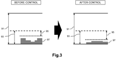
- FIGS. 1 to 3 are explanatory diagrams for explaining an example of band control. 1 to 3, a band 91, a band 93, a band 95, and a band 97 before and after band control are shown.
- the band 91 is the entire band of the line accommodating the base station used by the user of the 3GPP system.
- a band 93 is a band reserved for a base station used by a user of the 3GPP system.
- the band 95 is a band that can newly accept a user of the 3GPP system.
- the band 97 is a band that is actually used. For example, as shown in FIG. 1, the upper limit value of band 93 (band reserved for a base station used by a user of the 3GPP system) can be adjusted.
- the bandwidth 95 (band that can newly accept a user of the 3GPP system) can be reduced in a line where the number of users of the 3GPP system has increased.
- the bandwidth 95 (a bandwidth that can newly accept a 3GPP system user) can be increased.
- Such a band control technique is shown in 3GPP TS 23.139 V12.2.0.
- the base station newly accepts the upper limit value of the band 93 (band reserved for the base station used by the user of the 3GPP system) and / or the band 95 (user of the 3GPP system).
- admission control is also performed based on the available bandwidth.
- the admission control includes determining whether to accept a radio access bearer (RAB) of a UE (User Equipment) to be handed over. Thereby, the accommodation number of RAB for every base station can be optimized.
- RAB radio access bearer
- FIG. 4 is a sequence diagram for explaining a first example of a procedure for a fixed broadband access network.
- FIG. 4 is an example of a case where WCDMA (Wideband Code-Division Multiple Access) (registered trademark) is used as a communication method, and is FIG. 9.3.4-1 of 3GPP TS23.139 V12.2.0. .
- WCDMA Wideband Code-Division Multiple Access
- step 1 the target HNB sends the target HNB local IP address and UDP port number to the target SGSN (Serving GPRS (General Packet Radio Service) Support Node).
- target SGSN Serving GPRS (General Packet Radio Service) Support Node
- step 2a the target SGSN sends the target HNB local IP address and UDP port number to the S-GW (Serving Gateway), and in step 2b, the S-GW sends the target HNB local IP address and UDP port number to the P- Send to GW.
- S-GW Serving Gateway
- step 3 the P-GW sends the target HNB local IP address and UDP port number to the PCRF.
- step 4 the PCRF sends the target HNB local IP address and UDP port number to the fixed broadband access network.
- step 2a in FIG. 4 is executed when the following processing is executed in step 1.
- step 2a in FIG. 4 is executed when the following processing is executed in step 1.
- step 2a in FIG. 4 is executed when the following processing is executed in step 1.
- step 2a in FIG. 4 is executed when the following processing is executed in step 1.
- step 2a in FIG. 4 is executed when the following processing is executed in step 1.
- step 2a in FIG. 4 is executed when the following processing is executed in step 1.
- step 2a in FIG. 4 is executed when the following processing is executed in step 1.
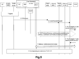
- FIG. 5 is a sequence diagram for explaining another example of the procedure for the fixed broadband access network.
- FIG. 5 is an example of a case where LTE (Long Term Evolution) is used as a communication method, which is FIG. 9.1.5 of 3GPP TS23.139 V12.2.0.
- LTE Long Term Evolution
- step 2 the target HeNB transmits the target HeNB local IP address and UDP port number to the MME.
- step 3 the MME transmits the target HeNB local IP address and UDP port number to the S-GW, and the S-GW transmits the target HeNB local IP address and UDP port number to the P-GW.
- step 4 the P-GW transmits the target HeNB local IP address and UDP port number to the PCRF.
- step 5 the PCRF transmits the target HeNB local IP address and UDP port number to the fixed broadband access network.
- step 2 in FIG. 5 is executed when the following processing is executed in step 1.
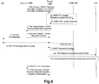
- FIG. 6 is an explanatory diagram for explaining a first example of a handover procedure in the home access network.
- FIG. 6 is FIG. 5.7.2.1-1 of 3GPP TS25.467 V12.3.0.
- the UE is handed over from the source HNB to the target HNB.
- HNB-GW Home Node B Gateway
- FIG. 7 is an explanatory diagram for explaining a second example of the handover procedure in the home access network.
- FIG. 7 is a diagram of FIG. 3-1.
- the UE is handed over from the source HNB to the target HNB.
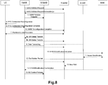
- FIG. 8 is an explanatory diagram for explaining an example of a SeNB change procedure.
- FIG. 8 is FIG. 10.1.2.8.4-1 of 3GPP TS36.300 V13.0.0.
- S-SeNB Source Secondary eNB
- T-SeNB Target Secondary eNB
- the MeNB sends an S1AP: E-RAB MODIFICATION INDICATION message to the MME. Send to.
- the MME requests Bearer Modification from the S-GW.
- the S1AP: E-RAB MODIFICATION INDICATION message does not include the local IP address and UDP port number of the T-SeNB, the MME confirms that the SCG bearer has moved from the S-SeNB to the T-SeNB. Cannot notify GW.
- the PCRF since the PCRF is not notified of the local IP address and UDP port number of the T-SeNB, the fixed broadband access network is not controlled (for example, bandwidth control). As a result, it may be impossible to maintain / improve communication quality of users of the 3GPP system and / or optimize the number of RABs accommodated for each base station.
- Step 10 is not executed. Therefore, similarly, maintenance / improvement of communication quality of users of the 3GPP system and / or optimization of the number of RABs accommodated for each base station may be impossible.
- Procedure for CSG 3GPP TS36.300 V13.0.0 stipulates that an eNB can configure a hybrid cell.
- a hybrid cell a user belonging to a CSG identified by an identifier called CSG ID uses the hybrid cell as a CSG cell, and a user who does not belong to the CSG uses the hybrid cell as a normal cell.
- the eNB that constitutes the hybrid cell decides whether to accept the UE to be handed over, and when to decide which bearer to accept and reject which bearer when accepting the UE to be handed over
- a user who uses a hybrid cell as a CSG cell may be favored over a user who uses a hybrid cell as a normal cell.
- SeNB configures a hybrid cell.
- the MeNB receives the CSG ID broadcast in the hybrid cell of the SeNB from the UE, and reports the CSG ID to the MME.
- MME determines whether UE uses the hybrid cell of SeNB as a CSG cell or a normal cell.
- 3GPP R3-1151949 and 3GPP R3-151995 disclose candidate determination procedures.
- the MeNB when the SCG bearer option is set in one of the bearer contexts in the SeNB, the MeNB includes the above CSG ID (the CSG ID broadcasted in the SeNB hybrid cell) S1AP: E -Send RAB MODIFICATION INDICATION message to MME.
- the MeNB sends an S1AP: UE CONTEXT MODIFICATION INDICATION message (including the CSG ID) ( A new message) is sent to the MME.
- the MeNB sends an S1AP: E-RAB MODIFICATION INDICATION message including the above CSG ID (CSG ID broadcasted in the SeNB hybrid cell) to the MME. To do.
- the message transmitted from the MeNB to the MME does not include the local IP address and UDP port number of the SeNB. Therefore, for example, bandwidth control of a fixed broadband access network is not performed. As a result, it may be impossible to maintain / improve communication quality of users of the 3GPP system and / or optimize the number of RABs accommodated for each base station.
- the PCRF of the 3GPP system receives the local IP address of the base station received from the P-GW (ie, the outer IP of the IPsec tunnel). Address, public IP address, or global IP address) and UDP port number are sent to the fixed broadband access network along with the QoS information in the PCRF.
- the fixed broadband access network converts the QoS information into DSCP, applies it to the line associated with the local IP address received from the PCRF and the UDP port number, and controls the bandwidth for the user of the 3GPP system. Do.
- the local IP address and UDP port number are not transmitted to the core network node.
- the local IP address and UDP port number of the SeNB after the change are not transmitted to the core network.
- the local IP address and UDP port number of the target HNB are not transmitted to the core network.
- control of the fixed broadband access network for example, bandwidth control
- maintenance / improvement of communication quality of users of the 3GPP system and / or optimization of the number of RABs accommodated for each base station is achieved. Can be impossible.
- An object of an embodiment of the present invention is to enable a core network node to acquire information necessary for controlling, for example, a fixed broadband access network in more cases.
- the SeNB is changed from the source SeNB to the target SeNB.
- the MeNB transmits a message including address information (for example, an IP address) and transport identification information (for example, a UDP port number) of the target SeNB to the MME.
- the MME receives the message.
- the HNB communicating with the UE is changed from the source HNB to the target HNB.
- the HNB-GW transmits a message including the address information (eg, IP address) and transport identification information (eg, UDP port number) of the target HNB to the SGSN core network node. Then, for example, the SGSN receives the message.
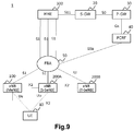
- FIG. 9 is an explanatory diagram illustrating an example of a schematic configuration of the system 1 according to the first embodiment.
- the system 1 includes a UE 10, an eNB 100, an eNB 200A, an eNB 200B, an MME 300, an S-GW 20, a P-GW 30, a PCRF 40, and an FBA (Fixed Broadband Access) 50.
- eNB 200A and eNB 200B may be simply referred to as eNB 200.
- UE10 supports dual connectivity and can communicate with MeNB and SeNB.
- eNB100 is eNB which can operate
- eNB200 is eNB which can operate
- the eNB 100 is an eNB (macro eNB) of a macro cell
- the eNB 200 is an eNB (small eNB) of a small cell (for example, a micro cell, a pico cell, or a femto cell).
- the eNB 200 is a home eNB. Note that the eNB 100 and the eNB 200 are not limited to this example.
- the eNB 100 operates as the MeNB for the UE 10
- the eNB 200A operates as the SeNB for the UE 10
- the UE 10 communicates with the eNB 100 (MeNB) and the eNB 200A (SeNB).
- the SeNB is changed from the eNB 200A (S-SeNB) to the eNB 200B (T-SeNB).
- the UE 10 comes to communicate with the eNB 100 (MeNB) and the eNB 200B (SeNB).
- the eNB 100 is connected to each of the eNB 200A and the eNB 200B via the X2 interface.
- An X2 gateway (X2GW) may exist between the eNB 100 and the eNB 200.
- X2GW X2 gateway
- each of eNB100, eNB200A, and eNB200B is connected with MME via S1 interface.
- the MME 300 is connected to the S-GW 20 via the S11 interface.
- the S-GW 20 is connected to the P-GW 30 via the S5 interface.
- the PCRF is a node for setting a policy in the network, connected to the P-GW 30 via the Gx interface, and connected to the FBA 50 via the S9a interface.
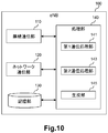
- FIG. 10 is a block diagram illustrating an example of a schematic configuration of the eNB 100 according to the first embodiment.
- the eNB 100 includes a radio communication unit 110, a network communication unit 120, a storage unit 130, and a processing unit 140.
- the wireless communication unit 110 transmits and receives signals wirelessly.
- the radio communication unit 110 receives a signal from the UE and transmits a signal to the UE.
- the network communication unit 120 receives a signal from a network (for example, backhaul) and transmits the signal to the network.
- a network for example, backhaul
- Storage unit 130 The storage unit 130 temporarily or permanently stores programs and parameters for the operation of the eNB 100 and various data.
- the processing unit 140 provides various functions of the eNB 100.
- the processing unit 140 includes a first communication processing unit 141, a second communication processing unit 143, and a generation unit 145.
- the processing unit 140 may further include other components other than these components. That is, the processing unit 140 can perform operations other than the operations of these components.
- the processing unit 140 (first communication processing unit 141) communicates with the UE via the wireless communication unit 110.
- the processing unit 140 (second communication processing unit 143) communicates with another network node (for example, eNB 200 or MME 300) via the network communication unit 120.
- another network node for example, eNB 200 or MME 300
- the wireless communication unit 110 may include an antenna and a radio frequency (RF) circuit.
- the network communication unit 120 may include a network adapter or a network interface card.
- the storage unit 130 may include a memory (for example, a nonvolatile memory and / or a volatile memory) and / or a hard disk.
- the processing unit 140 may include a baseband (BB) processor and / or another processor.
- BB baseband
- the SeNB for the UE 10 (that is, the SeNB that provides the UE 10 with additional radio resources in dual connectivity) is the eNB 200A (source SeNB) is changed to eNB 200B (target SeNB).
- the eNB 100 (second communication processing unit 143) transmits a first message including the address information and transport identification information of the eNB 200B (that is, the target SeNB) to the core network node.
- the eNB 100 (generating unit 145) generates the first message.
- (A) Core network node For example, the core network node is the MME 300.
- the first message includes tunnel information including the address information and the transport identification information. More specifically, for example, the tunnel information is Tunnel Information for BBF IE.
- the Tunnel Information for BBF IE includes an IP address (address information) and a UDP port number (transport identification information).
- the first message is an S1AP: E-RAB MODIFICATION INDICATION message.
- the eNB 100 transmits an S1AP: E-RAB MODIFICATION INDICATION message to the core network node.
- the eNB 100 may perform S1AP: Send an E-RAB MODIFICATION INDICATION message to the core network node. This makes it possible to convey address information and transport identification information using the same message regardless of the presence or absence of the SCG bearer.
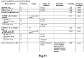
- FIG. 11 is an explanatory diagram for explaining an example of the S1AP: E-RAB MODIFICATION INDICATION message according to the first embodiment.
- information elements Information Elements: IE
- the S1AP: E-RAB MODIFICATION INDICATION message includes a Tunnel Information for BBF IE including an IP address (address information) and a UDP port number (transport identification information).
- eNB 100 When there is no SCG bearer for UE 10 and eNB 200A (S-SeNB) (that is, when there is only a split bearer), eNB 100 (second communication processing unit 143) sends other types of messages to the core You may transmit to a network node.
- S-SeNB S-SeNB
- the first message transmitted by the eNB 100 may be another type of message.
- the eNB 100 (generating unit 145) may acquire the first message from another node instead of generating the first message by itself.
- the eNB 100 (second communication processing unit 143) receives the second message including the address information and the transport identification information.
- the second message is a message transmitted by the eNB 200. This point will be described later in connection with the eNB 200. Thereby, for example, the eNB 100 can know the address information and transport identification information of the eNB 200.
- the address information is identification information (address) of the network layer (of the OSI (Open System Interconnection) reference model) or the Internet layer (of TCP / IP (Transmission Control Protocol / Internet Protocol)).
- the address information is an IP address.
- the IP address is a public IP address (or a global IP address).
- the IP address is a public IP address assigned to the eNB 200B (ie, the target SeNB) by the BBF domain in a no-NAT (Network Address Translation) case, or an RG (Residential Gateway) that performs NAT (ie, NATed RG).
- the IP address can be referred to as a “local IP address” in the 3GPP specifications.
- the transport identification information is identification information of a transport layer (OSI reference model or TCP / IP).
- the transport identification information is a UDP port number.
- the address information and the transport identification information are information provided to the FBA 50. More specifically, for example, the address information and the transport identification information are information provided from the PCRF 40 to the FBA 50. Thereby, for example, bandwidth control can be performed.
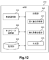
- FIG. 12 is a block diagram illustrating an example of a schematic configuration of the eNB 200 according to the first embodiment.
- the eNB 200 includes a radio communication unit 210, a network communication unit 220, a storage unit 230, and a processing unit 240.
- the wireless communication unit 210 transmits and receives signals wirelessly.
- the radio communication unit 210 receives a signal from the UE and transmits a signal to the UE.
- the network communication unit 220 receives a signal from a network (for example, backhaul) and transmits the signal to the network.
- a network for example, backhaul
- Storage unit 230 The storage unit 230 temporarily or permanently stores programs and parameters for the operation of the eNB 200 and various data.
- the processing unit 240 provides various functions of the eNB 200.
- the processing unit 240 includes a first communication processing unit 241, a second communication processing unit 243, and a generation unit 245. Note that the processing unit 240 may further include other components other than these components. That is, the processing unit 240 can perform operations other than the operations of these components.
- the processing unit 240 (first communication processing unit 241) communicates with the UE via the wireless communication unit 210.
- the processing unit 240 (second communication processing unit 243) communicates with other network nodes (for example, the eNB 100 or the MME 300) via the network communication unit 220.
- the wireless communication unit 210 may include an antenna, a radio frequency (RF) circuit, and the like.
- the network communication unit 220 may include a network adapter or a network interface card.
- the storage unit 230 may include a memory (for example, a nonvolatile memory and / or a volatile memory) and / or a hard disk.
- the processing unit 240 may include a baseband (BB) processor and / or another processor.
- BB baseband
- the eNB 200 can operate as a SeNB (that is, a SeNB that provides additional radio resources to the UE 10 in dual connectivity), and the eNB 100 can operate as a MeNB.
- the eNB 200 (second communication processing unit 243) transmits a message including the address information and transport identification information of the eNB 200 to the core network node that forwards the address information and the transport identification information to the eNB 100, or to the eNB 100.
- the eNB 200 (generating unit 245) generates the message.
- the eNB 100 can know the address information and transport identification information of the eNB 200.
- the fixed broadband access network can be controlled even in the case of dual connectivity (specifically, the case of SeNB change).
- the message includes tunnel information including the address information and the transport identification information. More specifically, for example, the tunnel information is Tunnel Information for BBF IE.
- the Tunnel Information for BBF IE includes an IP address (address information) and a UDP port number (transport identification information).
- the eNB 200 (second communication processing unit 243) transmits the message to the core network node.
- the core network node is the MME 300.
- the message is an S1AP: ENB CONFIGURATION TRANSFER message.
- the core network node MME 300 is a node that transmits to the eNB 100 an S1AP: MME CONFIGURATION TRANSFER message including the address information (IP address) and the transport identification information (UDP port number).
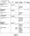
- S1AP ENB CONFIGURATION TRANSFER message and S1AP: MME CONFIGURATION TRANSFER message include SON Configuration Transfer In IE, SON Configuration Transfer In IE, and SON Configuration Transfer In IE.
- the X2 TNL Configuration Info IE includes the information elements as shown in FIG. 13, and particularly includes the Tunnel Information for BBF IE.
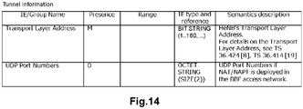
- Tunnel Information for BBF IE includes information elements as shown in FIG.
- the Tunnel Information for BBF IE includes a transport layer address and a UDP port number.
- the transport layer address is an IP address.
- the eNB 200 (second communication processing unit 243) transmits the message to the eNB 100.
- eNB200 (2nd communication process part 243) may transmit the said message to eNB100 directly, or may transmit the said message to eNB100 via X2GW.
- the message is an X2AP: X2 SETUP REQUEST message or an X2AP: X2 SETUP RESPONSE message.
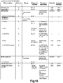
- the X2AP: X2 SETUP REQUEST message includes an information element as shown in FIG. 15, and in particular includes a Tunnel Information for BBF IE.
- Tunnel Information for BBF IE includes information elements as shown in FIG. That is, the Tunnel Information for BBF IE includes a transport layer address (that is, an IP address) and a UDP port number.
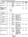
- the X2AP: X2 SETUP RESPONSE message includes an information element as shown in FIG. 16, and in particular includes a Tunnel Information for BBF IE.
- Tunnel Information for BBF IE includes information elements as shown in FIG. That is, the Tunnel Information for BBF IE includes a transport layer address (that is, an IP address) and a UDP port number.
- the eNB 200 may transmit the message to the eNB 100 as in the second example.
- eNB200 (2nd communication process part 243) may transmit the said message directly to eNB100, or may transmit the said message to eNB100 via X2 gateway (X2GW).
- X2GW X2 gateway
- the message may be an X2AP: SENB ADDITION REQUEST ACKNOWLEDGE message. That is, the eNB 200B (second communication processing unit 243) may transmit the message when the SeNB is changed from the eNB 200A (source SeNB) to the eNB 200B (target SeNB).
- the X2AP: SENB ADDITION REQUEST ACKNOWLEDGE message may include an information element as shown in FIG. 17, and in particular, may include Tunnel Information for BBF IE. Furthermore, the Tunnel Information for BBF IE may include information elements as shown in FIG. That is, the Tunnel Information for BBF IE may include a transport layer address (that is, an IP address) and a UDP port number.
- the said message transmitted by eNB200 is not limited to this example.
- the message transmitted by the eNB 200 may be another type of message.
- the address information is an IP address
- the transport identification information is a UDP port number.
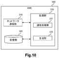
- FIG. 18 is a block diagram illustrating an example of a schematic configuration of the MME 300 according to the first embodiment.
- the MME 300 includes a network communication unit 310, a storage unit 320, and a processing unit 330.
- Network communication unit 310 The network communication unit 310 receives a signal from the network and transmits the signal to the network.
- Storage unit 320 The storage unit 320 temporarily or permanently stores programs and parameters for the operation of the MME 300 and various data.
- Processing unit 330 provides various functions of the MME 300.
- the processing unit 330 includes a communication processing unit 331 and a generation unit 333. Note that the processing unit 330 may further include other components other than these components. That is, the processing unit 330 can perform operations other than the operations of these components.
- the processing unit 330 communicates with the eNB via the network communication unit 310.
- the network communication unit 310 may include a network adapter or a network interface card.
- the storage unit 320 may include a memory (for example, a nonvolatile memory and / or a volatile memory) and / or a hard disk.
- the processing unit 330 may include a processor or the like.
- the SeNB for the UE 10 (that is, the SeNB that provides the UE 10 with additional radio resources in dual connectivity) becomes the eNB 200A (source SeNB).
- eNB200B target SeNB.
- the MME 300 receives a first message including the address information and transport identification information of the eNB 200B (target SeNB) from the eNB 100 (MeNB).
- the MME 300 transmits a second message including the address information and the transport identification information to the core network node.
- the MME 300 (generation unit 333) generates the second message.
- (A) Core network node For example, the core network node is the S-GW 20.
- the second message transmitted to the core network node is, for example, a MODIFY BEARER REQUEST message.
- the second message transmitted by the MME 300 is not limited to this example.
- the second message transmitted by the MME 300 may be another type of message.
- the address information is an IP address
- the transport identification information is a UDP port number.
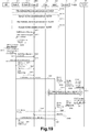
- FIG. 19 is a sequence diagram illustrating an example of a schematic flow of processing according to the first embodiment.
- the SeNB for the UE 10 is changed from the eNB 200A (source SeNB) to the eNB 200B (target SeNB). Therefore, here, the eNB 100, the eNB 200A, and the eNB 200B are denoted as the MeNB 100, the S-SeNB 200A, and the T-SeNB 200B, respectively.
- an X2 link is established between eNBs.
- an X2 link is established between the MeNB 100 and the T-SeNB 200B.
- the X2 link is established directly between eNBs or indirectly via X2GW.
- the X2 link can be established manually by the operator.
- the X2 link can be automatically established by SON (Self-Organization Network) defined in Chapter 22 of 3GPP TS36.300.
- SON is an automatic network optimization algorithm.
- both the MeNB 100 and the T-SeNB 200B can start the process of establishing the X2 link, but here, the MeNB 100 starts the process.
- the X2 link between the MeNB 100 and the S-SeNB 200A and the X2 link between the S-SeNB 200A and the T-SeNB 200B are also established by any of the four methods described above, but the description is omitted here. To do.
- the MeNB 100 transmits an S1AP: ENB CONFIGURATION TRANSFER message defined in 3GPP TS36.413 V13.0.0 to the MME 300.
- S1AP: The ENB CONFIGURATION TRANSFER message includes a SON Configuration Transfer IE, and the SON Configuration Transfer IE includes an X2 TNL Configuration Info IE (see FIG. 13). Further, the X2 TNL Configuration Info IE includes a Tunnel Information for BBF IE (see FIG. 14).
- Tunnel Information for BBF IE includes a local IP address (that is, a public IP address or a global IP address) of the MeNB 100 and a UDP port number.
- the MME 300 transmits the S1AP: MME CONFIGURATION TRANSFER message to the T-SeNB 200B.
- the S1AP: MME CONFIGURATION TRANSFER message includes the SON Configuration Transfer IE included in the S1AP: ENB CONFIGURATION TRANSFER message. That is, the SON Configuration Transfer IE is transmitted from the MeNB 100 to the T-SeNB 200B via the MME 300. Accordingly, the T-SeNB 200B can know the local IP address and UDP port number of the MeNB 100.
- the T-SeNB 200B transmits an S1AP: ENB CONFIGURATION TRANSFER message to the MME 300.
- the S1AP: ENB CONFIGURATION TRANSFER message includes the information element (IE) as described above, but here includes the local IP address and UDP port number of the T-SeNB.
- IE information element
- the MME 300 transmits the S1AP: MME CONFIGURATION TRANSFER message to the MeNB 100 in response to the reception of the S1AP: ENB CONFIGURATION TRANSFER message.
- the S1AP: MME CONFIGURATION TRANSFER message includes the SON Configuration Transfer IE included in the S1AP: ENB CONFIGURATION TRANSFER message. That is, the SON Configuration Transfer IE is transmitted from the T-SeNB 200B to the MeNB 100B via the MME 300.
- the MeNB 100 can know the local IP address and UDP port number of the T-SeNB 200B.
- the MeNB 100 uses the X2AP: X2 SETUP defined in 3GPP TS36.423 V13.0.0 based on the setting by the operator (for example, the setting of the local IP address and UDP port number of the T-SeNB 200B (as the destination)).
- a REQUEST message (see FIG. 15) is transmitted to the T-SeNB 200B.
- the X2AP: X2 SETUP REQUEST message includes the MeNB's local IP address and UDP port number. Accordingly, the T-SeNB 200B can know the local IP address and UDP port number of the MeNB 100.
- the T-SeNB 200B transmits an X2AP: X2 SETUP RESPONSE message (see FIG. 16) defined in 3GPP TS36.423 V13.0.0 to the MeNB 100.
- the X2AP: X2 SETUP RESPONSE message includes the local IP address and UDP port number of the T-SeNB 200B.
- the MeNB 100 can know the local IP address and UDP port number of the T-SeNB 200B.
- the T-SeNB 200B transmits an X2AP: X2 SETUP REQUEST message (see FIG. 15) to the MeNB 100, and the MeNB 100 sends an X2AP: X2 SETUP RESPONSE message (see FIG. 16) to the T. -You may transmit to SeNB200B.
- step S401C processing of the X2AP message between the MeNB 100 and the X2GW and processing of the X2AP message between the X2GW and the T-SeNB 200B (that is, 2.2.3.6.1 of 3GPP TS36.300 V13.0.0). Except for the processing added to the chapter procedure). Therefore, the overlapping description is omitted here.
- -S401D MeNB100 transmits X2AP: X2AP MESSAGE TRANSFER message defined in 3GPP TS36.423 V13.0.0 to X2GW (T-SeNB200B).
- the X2AP MESSAGE TRANSFER message includes an X2AP: X2 SETUP REQUEST message (see FIG. 15). That is, the MeNB 100 transmits an X2AP: X2 SETUP REQUEST message to the T-SeNB 200B via the X2GW.
- the X2AP: X2 SETUP REQUEST message includes the local IP address and UDP port number of the MeNB 100. Accordingly, the T-SeNB 200B can know the local IP address and UDP port number of the MeNB 100.
- T-SeNB 200B transmits the X2AP: X2AP MESSAGE TRANSFER message defined in 3GPP TS36.423 V13.0.0 to X2GW (MeNB100).
- the X2AP MESSAGE TRANSFER message includes an X2AP: X2 SETUP RESPONSE message (see FIG. 16). That is, the T-SeNB 200B transmits an X2AP: X2 SETUP RESPONSE message to the MeNB 100 via the X2GW.
- the X2AP: X2 SETUP RESPONSE message includes the local IP address and UDP port number of the T-SeNB 200B. As a result, the MeNB 100 can know the local IP address and UDP port number of the T-SeNB 200B.
- the T-SeNB 200B transmits an X2AP: X2 SETUP REQUEST message (see FIG. 15) to the MeNB 100, and the MeNB 100 sends an X2AP: X2 SETUP RESPONSE message (see FIG. 16) to the T. -You may transmit to SeNB200B.
- the dual connectivity of the UE 10 is started at any timing after the completion of step S401. More specifically, the UE 10 starts to communicate with both the MeNB 100 and the S-SeNB 200A.
- the MeNB 100 transmits an X2AP: SENB ADDITION REQUEST message to the T-SeNB 200B. Thereby, MeNB00 requests
- T-SeNB 200B transmits an X2AP: SENB ADDITION REQUEST ACKNOWLEDGE message to the MeNB 100. Thereby, T-SeNB200B notifies MeNB100 that the resource for UE10 was allocated.
- the X2AP: SENB ADDITION REQUEST ACKNOWLEDGE message may include an information element as shown in FIG. 17, and in particular, may include a Tunnel Information for BBF IE. Furthermore, the Tunnel Information for BBF IE may include information elements as shown in FIG. 17,
- the MeNB 100 transmits an X2AP: SENB RELEASE REQUEST message to the S-SeNB 200A. Thereby, the S-SeNB 200A releases resources for the UE 10.
- the MeNB 10 instructs the UE 10 to apply a new configuration.
- the MeNB 100 transmits an X2AP: SENB RECONFIGURATION COMPLETE message to the T-SeNB 200B. As a result, the MeNB 100 notifies the T-SeNB 200B of the success of the RRC connection reconfiguration procedure.
- S425-S429) Data is transferred from the S-SeNB 200A to the T-SeNB 200B.
- S431 When there is an SCG bearer When there is an SCG bearer for UE 10 and S-SeNB 200A (ie, when the SCG bearer option is set), the MeNB 100 sends an S1AP: E-RAB MODIFICATION INDICATION message (see FIG. 11). ) To the MME 300.
- E-RAB MODIFICATION INDICATION message includes Tunnel Information for BBF IE. Further, Tunnel Information for BBF IE includes the local IP address and UDP port number of T-SeNB 200B.
- MeNB100 Does not transmit the S1AP: E-RAB MODIFICATION INDICATION message to the MME 300.
- the MeNB 100 transmits an S1AP: E-RAB MODIFICATION INDICATION message to the MME 300.
- E-RAB MODIFICATION INDICATION message includes Tunnel Information for BBF IE. Further, Tunnel Information for BBF IE includes the local IP address and UDP port number of T-SeNB 200B.
- the MME 100 transmits a MODIFY BEARER REQUEST message to the S-GW 20 regardless of the presence or absence of the SCG bearer for the UE 10 and the S-SeNB 200A.
- the S-GW 20 updates the data path when there is the SCG bearer, and updates the data path when there is no SCG bearer (that is, when there is only the split bearer). Absent.
- the S-GW 20 transmits a Modify Bearer Request message (including the local IP address and UDP port number of the T-SeNB 200B) to the P-GW 30.
- the P-GW 30 transmits an IP-CAN session modification request message (including the local IP address and UDP port number of the T-SeNB 200B) to the PCRF 40.
- the PCRF 40 executes a Gateway control and QoS Rule provisioning procedure (including transmission and reception of the local IP address and UDP port number of the T-SeNB 200B) with the FBA 50.
- the FBA 50 applies the QoS information converted to DSCP to the line corresponding to the local IP address and UDP port number of the T-SeNB 200B received from the PCRF 40.
- the FBA 50 performs bandwidth control for the line to which the T-SeNB 200B is connected.
- the upper limit value of the band (band 93) reserved for the base station used by the user of the 3GPP system can be adjusted for the above line.
- a band (band 95) that can newly accept a user of the 3GPP system can be reduced for the above line.
- the PCRF 40 transmits an IP-CAN session modification Acknowledge message to the P-GW 30.
- the P-GW 30 transmits a Modify Bearer Response to the S-GW 20.
- the S-GW 20 transmits a Modify Bearer Response message to the MME 300.
- the MME 300 transmits an S1AP: E-RAB MODIFICATION CONFIRM message to the MeNB 100.
- the MeNB 100 transmits an X2AP: UE CONTEXT RELEASE message to the S-SeNB 200A. Thereby, the S-SeNB 200A releases the UE context.
- step S447 is executed after step S445, but step S447 may be executed at any timing after step S433.
- X2AP SETUP REQUEST message
- X2AP XEN SETUP REQUEST ACKNOWLEDGE R message s
- S1AP MME CONFIGURATION TRANSFER message
- S1AP E-RAB MODIFICATION INDICATION message
- these messages are merely examples, and other messages including an IP address and a UDP port number (for example, Tunnel Information for BBF IE) may be used.
- a network node (for example, eNB 100, eNB 200, MME 300, S-GW 20, P-GW 30 and / or PCRF 40) is not composed of individual hardware, but VNF (Virtualized Network Function ) As a virtual machine. That is, NFV (Network Function Virtualization) may be used. Network nodes operating as VFNs on virtual machines may be managed and organized by a function called MANO (Management and Orchestration).
- MANO Management and Orchestration
- an SDN (Software-Defined Network) controller in which the MANO that manages the VNF of a network node (for example, eNB 100, eNB 200, MME 300, S-GW 20, P-GW 30 and / or PCRF 40) of the cellular network is a component of the FBA Also manage.
- the bandwidth control of the FBA 50 may be performed by the MANO instead of the PCRF 50 that is the VFN.
- a function corresponding to the PCRF 40 may exist in a RAN (Radio Access Network).
- the RAN may perform control (for example, bandwidth control) of the fixed broadband access network (FBA 50).
- FBA 50 fixed broadband access network
- the eNB 100 may transmit the first message to a node having the above function instead of the MME 300.
- the MME 300 may transmit the second message to a node having the above function instead of the S-GW 20.
- 3GPP R2-153972 proposes LTE-WLAN (Wireless Local Area Network) aggregation (LWA).
- LWA Long Term Evolution
- the UE communicates using both LTE and WLAN.
- the eNB transmits data to the WLAN via the Xw interface.
- the same method as the above-described example of the first embodiment is also applied to the LWA case. May be. Thereby, it is possible to maintain / improve the communication quality of users of the 3GPP system and / or optimize the number of UEs accommodated for each base station.
- FIG. 20 is an explanatory diagram illustrating an example of a schematic configuration of a system according to a third modification of the first embodiment.
- the system includes eNB 100, WLAN Termination (WT) 201A, WT 201B, WLAN AP 203A, WLAN AP 203B, and MME 300. Further, the system includes UE 10, S-GW 20, P-GW 30, PCRF 40, and FBA 50.
- each of WT 201A and WT 201B may simply be referred to as WT 201.
- each of the WLAN AP 203A and the WLAN AP 203B can be simply referred to as the WLAN AP 203.
- the WT 201 terminates the Xw interface.
- the WLAN AP 203 belongs to a WLAN mobility set (that is, a set of one or more WLAN APs).
- the WLAN mobility set shares a common WT 201.
- the WLAN AP 203A belongs to the first WLAN mobility set, and the first WLAN mobility set shares the WT 201A.
- the WLAN AP 203B belongs to the second WLAN mobility set, and the second WLAN mobility set shares the WT 201B.
- the UE 10 supports LWA and can communicate with eNB 100 and WLAN AP 203.
- the UE 10 communicates with the eNB 100 and the WLAN AP 203A via LWA.
- the AP with which the UE 10 communicates is changed from the WLAN AP 203A (S-AP) to the WLAN AP 203B (T-AP).
- S-AP WLAN AP 203A
- T-AP WLAN AP 203B
- the WLAN AP that communicates with the UE 10 with which the eNB 100 communicates (that is, the WLAN AP for LTE-WLAN aggregation) is changed from the WLAN AP 203A to the WLAN AP 203B.
- the eNB 100 (second communication processing unit 143) transmits a first message including the address information and transport identification information of the WLAN AP 203B to the core network node (for example, the MME 300).
- the eNB 100 (generating unit 145) generates the first message.
- the MME 300 receives the first message from the eNB 100. Then, the MME 300 (communication processing unit 331) transmits a second message including the address information and the transport identification information to the core network node (for example, the S-GW 20). For example, the MME 300 (generation unit 333) generates the second message.
- the WLAN AP 203B (communication processing unit) transmits a third message including the address information and transport identification information of the WLAN AP 203B to the eNB 100 (for example, via the WT 201B).
- the WLAN AP 203B (generation unit) generates the third message.
- the WT 201B (communication processing unit) may transmit a third message including the address information and transport identification information of the WLAN AP 203B to the eNB 100.
- the WT 201B (generation unit) may generate the third message.
- the core network node can acquire information necessary for controlling the fixed broadband access network.
- communication quality of users of the 3GPP system can be maintained / improved, and the number of RABs accommodated for each base station can be optimized.
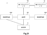
- FIG. 21 is an explanatory diagram illustrating an example of a schematic configuration of the system 2 according to the second embodiment.
- the system 2 includes a terminal device 11, a base station 500, a wireless communication device 600A, a wireless communication device 600B, a first core network node 700, and a second core network node 60. Note that when it is not necessary to distinguish between the wireless communication device 600A and the wireless communication device 600B, each of the wireless communication device 600A and the wireless communication device 600B may be simply referred to as the wireless communication device 600.
- the terminal device 11 is a UE
- the base station 500 is an eNB
- the first core network node 700 is an MME
- the second core network node 60 is an S-GW.
- the terminal device 11 can communicate with the base station 500 and the wireless communication device 600.
- the wireless communication device 600 can communicate with the terminal device 11 with which the base station 500 communicates.
- the wireless communication device communicating with the terminal device 11 with which the base station 500 communicates can be changed from the wireless communication device 600A to the wireless communication device 600B.
- the terminal device 11 supports dual connectivity.
- the wireless communication device 600 is a base station that can operate as a secondary base station that provides additional wireless resources to the terminal device 11 in dual connectivity.
- the radio communication device 600 is an eNB that can operate as a SeNB.
- the radio communication apparatus 600 is a home eNB, but is not limited to this example.
- the base station 500 can operate as a master base station corresponding to the secondary base station.
- the base station 500 is an eNB that can operate as a MeNB.
- the secondary base station for the terminal apparatus 11 can be changed from the wireless communication apparatus 600A to the wireless communication apparatus 600B.
- the terminal device 11 may support aggregation of different radio access technologies.
- the aggregation may be LTE-WLAN aggregation (LWA).
- the wireless communication device 600 may be an access point (AP) that uses a wireless access technology different from that of the base station 500.
- the wireless communication device 600 may be a WLAN AP.
- the wireless communication apparatus 600 may communicate with the base station 500 via WLAN Termination (WT).
- WT WLAN Termination
- the wireless communication device 600A may be a first AP belonging to the first mobility set, and the wireless communication device 600B is a second AP belonging to a second mobility set different from the first mobility set. There may be.
- the first mobility set may share a first WT and the second mobility set may share a second WT.
- the AP communicating with the terminal device 11 with which the base station 500 communicates may be changed from the wireless communication device 600A to the wireless communication device 600B.
- FIG. 22 is a block diagram illustrating an example of a schematic configuration of a base station 500 according to the second embodiment.
- the base station 500 includes a communication processing unit 503.
- the communication processing unit 503 can be implemented by a processor or the like.
- the wireless communication device that communicates with the terminal device 11 with which the base station 500 communicates is changed from the wireless communication device 600A to the wireless communication device 600B.
- base station 500 (communication processing unit 503) transmits a first message including address information and transport identification information of radio communication apparatus 600B to first core network node 700.
- the wireless communication device 600 is a base station that can operate as a secondary base station (for example, SeNB) that provides additional wireless resources to the terminal device 11 in dual connectivity.
- the base station 500 can operate as a master base station (for example, MeNB) corresponding to the secondary base station.
- the fixed broadband access network can be controlled.
- communication quality of users of the 3GPP system can be maintained / improved, and the number of RABs accommodated for each base station can be optimized.
- the wireless communication device 600 may be an AP (for example, WLAN AP) that uses a wireless access technology different from that of the base station 500.
- AP for example, WLAN AP
- the fixed broadband access network can also be controlled in such a case of aggregation of different radio access technologies (for example, LTE-WLAN aggregation) (for example, a case of changing WLAN AP).
- LTE-WLAN aggregation for example, a case of changing WLAN AP.
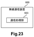
- FIG. 23 is a block diagram illustrating an example of a schematic configuration of a wireless communication apparatus 600 according to the second embodiment.
- the wireless communication device 600 includes a communication processing unit 603.
- the communication processing unit 603 can be implemented by a processor or the like.
- the wireless communication device 600 (communication processing unit 603) transmits a message including the address information and transport identification information of the wireless communication device 600 to the base station 500, for example.
- the wireless communication device 600 (communication processing unit 603) transmits the message to a core network node (for example, the first core network node 700) that transfers the address information and the transport identification information to the base station 500. May be.
- the base station 500 can know the address information and transport identification information of the wireless communication apparatus 600. As a result, control of the fixed broadband access network can be performed.
- the wireless communication device 600 is a base station that can operate as a secondary base station (for example, SeNB) that provides additional wireless resources to the terminal device 11 in dual connectivity.
- the base station 500 can operate as a master base station (for example, MeNB) corresponding to the secondary base station.
- the wireless communication device 600 may be an AP (for example, WLAN AP) that uses a wireless access technology different from that of the base station 500.
- AP for example, WLAN AP
- FIG. 24 is a block diagram illustrating an example of a schematic configuration of the first core network node 700 according to the second embodiment.
- the first core network node 700 includes a communication processing unit 701.
- the communication processing unit 701 can be implemented by a processor or the like.
- the wireless communication device that communicates with the terminal device 11 with which the base station 500 communicates is changed from the wireless communication device 600A to the wireless communication device 600B.
- the first core network node 700 receives a first message including the address information and transport identification information of the wireless communication device 600B from the base station 500. Then, the first core network node 700 (communication processing unit 701) transmits a second message including the address information and the transport identification information to the second core network node 60.
- the wireless communication device 600 is a base station that can operate as a secondary base station (for example, SeNB) that provides additional wireless resources to the terminal device 11 in dual connectivity.
- the base station 500 can operate as a master base station (for example, MeNB) corresponding to the secondary base station.
- the fixed broadband access network can be controlled.
- communication quality of users of the 3GPP system can be maintained / improved, and the number of RABs accommodated for each base station can be optimized.
- the wireless communication device 600 may be an AP (for example, WLAN AP) that uses a wireless access technology different from that of the base station 500.
- AP for example, WLAN AP
- the fixed broadband access network can also be controlled in such a case of aggregation of different radio access technologies (for example, LTE-WLAN aggregation) (specifically, a case of changing an access point).
- LTE-WLAN aggregation for example, LTE-WLAN aggregation
- a case of changing an access point for example, LTE-WLAN aggregation
- communication quality of users of the 3GPP system can be maintained / improved, and the number of RABs accommodated for each base station can be optimized.
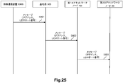
- FIG. 25 is a sequence diagram illustrating an example of a schematic flow of processing according to the second embodiment.
- Radio communication apparatus 600 transmits a message including address information and transport identification information of radio communication apparatus 600 to base station 500.
- the wireless communication device that communicates with the terminal device 11 with which the base station 500 communicates is changed from the wireless communication device 600A to the wireless communication device 600B.
- base station 500 transmits a first message including address information and transport identification information of radio communication apparatus 600B to first core network node 700.
- the first core network node 700 receives the first message from the base station 500.
- the first core network node 700 transmits a second message including the address information and the transport identification information to the second core network node 60.
- the wireless communication device 600 (for example, WLAN AP) transmits a message including the address information and transport identification information of the wireless communication device 600 to the base Transmit to station 500.
- a termination device for example, WT
- a message including port identification information may be transmitted to base station 500.
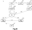
- FIG. 26 is an explanatory diagram illustrating an example of a schematic configuration of the system 3 according to the third embodiment.
- the system 3 includes UE 10, HNB 70A, HNB 70B, HNB-GW 1100, SGSN 1200, S-GW 20, P-GW 30, PCRF 40 and FBA 50.
- HNB 70A and HNB 70B may be simply referred to as HNB 70.
- the UE 10 communicates with SGSN 1200 via HNB 70 and HNB-GW 1100.
- the UE 10 communicates with the HNB 70A.
- the HNB communicating with the UE 10 is changed from the HNB 70A (S-HNB (Serving Home Node B)) to the HNB 70B (T-HNB (Target Home Node B)). That is, the handover of the UE 10 from the HNB 70A to the HNB 70B is performed.
- S-HNB Serving Home Node B
- T-HNB Target Home Node B
- the HNB 70 is connected to the HNB-GW 1100 via the FBA 50.
- the HNB 70 is connected to the HNB-GW 1100 via the Iuh interface.
- the HNB 70 is served by the HNB-GW 1100.
- the HNB 70A and the HNB 70B are connected to each other via the Iurh interface, and communicate directly via the Iurh interface when executing a handover (for example, as shown in FIGS. 6 and 7).
- the HNB 70A and HNB 70B may communicate indirectly via the HNB-GW 1100 when performing a handover (eg, as shown in FIGS. 6 and 7).
- the HNB-GW 1100 is connected to the SGSN 1200 via the Iu-PS interface.
- the SGSN 1200 is connected to the S-GW 20 via the S4 interface.
- the S-GW 20 is connected to the P-GW 30 via the S5 interface.
- the PCRF is a node for setting a policy in the network, connected to the P-GW 30 via the Gx interface, and connected to the FBA 50 via the S9a interface.
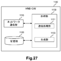
- FIG. 27 is a block diagram illustrating an example of a schematic configuration of the HNB-GW 1100 according to the third embodiment.
- the HNB-GW 1100 includes a network communication unit 1110, a storage unit 1120, and a processing unit 1130.
- the network communication unit 1110 receives a signal from the network and transmits the signal to the network.
- Storage unit 1120 The storage unit 1120 temporarily or permanently stores programs and parameters for the operation of the HNB-GW 1100 and various data.
- Processing unit 1130 provides various functions of the HNB-GW 1100.
- the processing unit 1130 includes a communication processing unit 1131 and a generation unit 1133. Note that the processing unit 1130 may further include other components other than these components. That is, the processing unit 1130 can perform operations other than the operations of these components.
- the processing unit 1130 communicates with other network nodes (for example, the HNB 70 and the SGSN 1200) via the network communication unit 1110.
- the network communication unit 1110 may include a network adapter or a network interface card.
- the storage unit 1120 may include a memory (for example, a nonvolatile memory and / or a volatile memory) and / or a hard disk.
- the processing unit 1130 may include a processor or the like.
- the HNB communicating with the UE 10 is changed from the HNB 70A to the HNB 70B.
- HNB-GW 1100 (communication processing unit 1131) transmits a message including the address information and transport identification information of HNB 70B to the core network node.
- the HNB-GW 1100 (generation unit 1133) generates the message.
- (A) Core network node For example, the said core network node is SGSN1200.
- the message includes tunnel information including the address information and the transport identification information. More specifically, for example, the tunnel information is Tunnel Information for BBF IE.
- the Tunnel Information for BBF IE includes an IP address (address information) and a UDP port number (transport identification information).
- the message is a RANAP: RELOCATION COMPLETE message.
- FIG. 28 is an explanatory diagram for explaining an example of a RANAP: RELOCATION COMPLETE message according to the third embodiment.
- an information element (IE) included in the RANAP: RELOCATION COMPLETE message is shown.
- the RANAP: RELOCATION COMPLETE message includes a Tunnel Information for BBF IE including an IP address (address information) and a UDP port number (transport identification information).
- the HNB-GW 1100 (generating unit 1133) may acquire the message from another node (for example, the HNB 70) instead of generating the message itself.
- the address information is identification information (address) of the network layer (of the OSI reference model) or the Internet layer (of TCP / IP).
- the address information is an IP address.
- the IP address is a public IP address (or a global IP address).
- the IP address is a public IP address assigned to HNB70B (ie, target HNB) by BBF domain in the no-NAT case, or RG that performs NAT (ie, , NATed RG), which is a public IP address assigned by the BBF domain and used for the HNB 70B.
- the IP address may be referred to as a “local IP address” or an “H (e) NB local IP address” in the 3GPP specifications.
- the transport identification information is identification information of a transport layer (OSI reference model or TCP / IP).
- the transport identification information is a UDP port number.
- the address information and the transport identification information are information provided to the FBA 50. More specifically, for example, the address information and the transport identification information are information provided from the PCRF 40 to the FBA 50. Thereby, for example, bandwidth control can be performed.
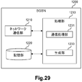
- FIG. 29 is a block diagram illustrating an example of a schematic configuration of an SGSN 1200 according to the third embodiment.
- the SGSN 1200 includes a network communication unit 1210, a storage unit 1220, and a processing unit 1230.
- the network communication unit 1210 receives a signal from the network and transmits the signal to the network.
- Storage unit 1220 The storage unit 1220 temporarily or permanently stores programs and parameters for the operation of the SGSN 1200 and various data.
- Processing unit 1230 provides various functions of the SGSN 1200.
- the processing unit 1230 includes a communication processing unit 1231 and a generation unit 1233. Note that the processing unit 1230 may further include other components other than these components. That is, the processing unit 1230 can perform operations other than the operations of these components.
- the processing unit 1230 communicates with other network nodes (for example, HNB-GW 1100 and S-GW 20) via the network communication unit 1210.
- the network communication unit 1210 may include a network adapter or a network interface card.
- the storage unit 1220 may include a memory (for example, a nonvolatile memory and / or a volatile memory) and / or a hard disk.
- the processing unit 1230 may include a processor or the like.
- the HNB communicating with the UE 10 is changed from the HNB 70A to the HNB 70B. That is, the handover of the UE 10 from the HNB 70A to the HNB 70B is performed.
- SGSN 1200 receives from HNB-GW 1100 a first message including the address information of HNB 70B and transport identification information.
- the SGSN 1200 transmits a second message including the address information and the transport identification information to the core network node.
- the SGSN 1200 (generation unit 1233) generates the second message.
- (A) Core network node For example, the core network node is the S-GW 20.
- the second message transmitted to the core network node is, for example, a MODIFY BEARER REQUEST message.
- the address information is an IP address
- the transport identification information is a UDP port number.
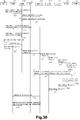
- FIG. 30 is a sequence diagram illustrating a first example of a schematic flow of a process according to the third embodiment.
- the first example is an example of a case where there is an Iurh interface between the HNB 70A and the HNB 70B.
- the UE 10 is communicating with the HNB 70A, but the HNB communicating with the UE 10 is changed from the HNB 70A to the HNB 70B. That is, the handover of the UE 10 from the HNB 70A to the HNB 70B is performed. Therefore, here, HNB 70A and HNB 70B are denoted as S-HNB 70A and T-HNB 70B, respectively. Note that RAB release does not occur after the handover.
- the S-HNB 70A confirms the access right of the UE 10. If the UE 10 has the access right, the S-HNB 70A transmits an RNA: CONNECT message (including an RNSAP: ENHANCED RELOCATION REQUEST message) to the T-HNB 70B.
- RNA: CONNECT message including an RNSAP: ENHANCED RELOCATION REQUEST message
- the T-HNB 70B transmits an HNBAP: TNL UPDATE REQUEST message to the HNB-GW 1100.
- HNBAP TNL UPDATE REQUEST message
- the transport network layer information related to the RAB transferred from the S-HNB 70A to the T-HNB 70B is updated.
- the HNB-GW 1100 transmits an HNBAP: TNL UPDATE RESPONSE message to the T-HNB 70B.
- the T-HNB 70B transmits an RNA: DIRECT TRANSFER message (including an RNSAP: ENHANCED RELOCATION RESPONSE message) to the S-HNB 70A.
- the T-HNB 70B notifies the S-HNB 70A that the UE 10 is ready for handover.
- the S-HNB 70A transmits an RNA: DIRECT TRANSFER message (including an RNSAP: RELOCATION COMMIT message). Thereby, the handover of the UE 10 to the T-HNB 70B is executed.
- the UE 10 transmits an RRC: RADIO BEARER RECONFIGRATION COMPLETE message to the T-HNB 70B. Thereby, the RRC Reconfiguration procedure is completed.
- the T-HNB 70B transmits an HNBAP: RELOCATION COMPLETE message to the HNB-GW 1100. Thereby, the T-HNB 70B notifies the HNB-GW 1100 that the handover of the UE 10 is successful. The HNB-GW 1100 switches the U-plane to the T-HNB 70B.
- the HNB-GW 1100 knows that the UE 10 has been handed over from the S-HNB 70A to the T-HNB 70B by receiving the HNBAP: RELOCATION COMPLETE message from the T-HNB 70B. Then, the HNB-GW 1100 transmits a RANAP: RELOCATION COMPLETE message (see FIG. 28) to the SGSN 1200.
- RELOCATION COMPLETE message includes Tunnel Information for BBF IE. Furthermore, Tunnel Information for BBF IE includes the local IP address and UDP port number of T-HNB70B.
- the SGSN sends a RANAP: RELOCATION COMMAND message to the S-HNB (ie, instructs the S-HNB to perform a handover), and then RANAP: RELOCATION A COMPLETE message is received from the T-HNB 70B. That is, the RANAP: RELOCATION COMPLETE message is transmitted and received during such a series of processes.
- the HNB-GW 1100 transmits to the RANAP: RELOCATION COMPLETE message SGSN 1200 without prior processing.
- the RANAP: RELOCATION COMPLETE message is merely an example, and other types of messages (for example, other types of RANAP messages) including the local IP address and UDP port number of the T-HNB 70B may be transmitted.
- the SGSN 1200 knows that the UE 10 has been handed over from the S-HNB 70A to the T-HNB 70B by receiving the RANAP: RELOCATION COMPLETE message (see FIG. 28) from the T-HNB 70B. SGSN 1200 obtains the local IP address and UDP port number of T-HNB 70B included in the RANAP RELOCATION COMPLETE message. Then, the SGSN 1200 transmits a Modify Bearer Request message including the IP address and the UDP port number to the S-GW 20.
- the SGSN sends a RANAP: RELOCATION COMMAND message to the S-HNB (ie, instructs the S-HNB to perform a handover), and then RANAP: RELOCATION A COMPLETE message is received from the T-HNB 70B.
- the SGSN 1200 receives the RANAP: RELOCATION COMPLETE message without transmitting the RANAP: RELOCATION COMMAND message, and transmits the Modify Bearer Request message.
- the S-GW 20 transmits a Modify Bearer Request message (including the local IP address of the T-HNB 70B and the UDP port number) to the P-GW 30.
- the P-GW 30 transmits an IP-CAN session modification request message (including the local IP address of the T-HNB 70B and the UDP port number) to the PCRF 40.
- the PCRF 40 executes a Gateway control and QoS Rule provisioning procedure (including transmission and reception of the local IP address and UDP port number of the T-SeNB 200B) with the FBA 50.
- the FBA 50 applies the QoS information converted to DSCP to the line corresponding to the local IP address and UDP port number of the T-SeNB 200B received from the PCRF 40.
- the FBA 50 performs bandwidth control for the line to which the T-SeNB 200B is connected.
- the upper limit value of the band (band 93) reserved for the base station used by the user of the 3GPP system can be adjusted for the above line.
- a band (band 95) that can newly accept a user of the 3GPP system can be reduced for the above line.
- the PCRF 40 transmits an IP-CAN session modification Acknowledge message to the P-GW 30.
- the P-GW 30 transmits a Modify Bearer Response to the S-GW 20.
- the S-GW 20 transmits a Modify Bearer Response message to the SGSN 1200.
- the HNB-GW 1100 transmits an HNBAP: UE-DEREGISTER message to the S-HNB 70A. As a result, the HNB-GW 1100 notifies the S-HNB 70A that the handover has succeeded.
- the S-HNB 70A transmits an RNA: DISCONNECT message (including an RNSAP: ENHANCED RELOCATION SIGNALING TRANSFER message) to the T-HNB 70B.
- step S1333 is executed after step S1331, but step S1333 may be executed at any timing after step S1315.
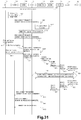
- FIG. 31 is a sequence diagram illustrating a second example of a schematic flow of a process according to the third embodiment.
- the second example is an example of the case where there is no Iurh interface between the HNB 70A and the HNB 70B.
- the UE 10 is communicating with the HNB 70A, but the HNB communicating with the UE 10 is changed from the HNB 70A to the HNB 70B. That is, the handover of the UE 10 from the HNB 70A to the HNB 70B is performed. Therefore, here, HNB 70A and HNB 70B are denoted as S-HNB 70A and T-HNB 70B, respectively. Note that RAB release does not occur after the handover.
- the UE 10 has established an active PS (Packet Switched) session with the SGSN 1200 via the S-HNB 70A and the HNB-GW 1100.
- PS Packet Switched
- the S-HNB 70A decides to move the UE 10 session to the T-HNB 70B.
- the S-HNB 70A transmits an RNA: DIRECT TRANSFER message (including a RANAP: RELOCATION REQUIRED message) to the HNB-GW 1100.
- the HNB-GW 1100 generates a RANAP: RELOCATION REQUEST message.
- the HNB-GW 1100 transmits a RANAP: RELOCATION REQUEST message to the T-HNB 70B.
- the T-HNB 70B allocates resources for handover. Thereafter, the T-HNB 70B transmits a RANAP: RELOCATION REQUEST ACKNOWLEDGE message.
- the HNB-GW 1100 transmits RUA: DIRECT TRANSFER (including RANAP: RELOCATION COMMAND) to the S-HNB 70A.
- the S-HNB 70A causes the UE 10 to execute Physical Channel Reconfiguration.
- the T-HNB 70B transmits an RUA: DIRECT TRANSFER message (including a RANAP: RELOCATION DETECT message) to the HNB-GW 1100.
- the T-HNB 70B transmits an RUA: DIRECT TRANSFER message (including a RANAP: RELOCATION COMPLETE message) to the HNB-GW 1100.
- the HNB-GW 1100 knows that the UE 10 has been handed over from the S-HNB 70A to the T-HNB 70B by receiving the RUA: DIRECT TRANSFER message from the T-HNB 70B. Then, the HNB-GW 1100 transmits a RANAP: RELOCATION COMPLETE message (see FIG. 28) to the SGSN 1200.
- step S1317 A more specific description of this step is the same as the description of step S1317 described above, for example. Therefore, the overlapping description is omitted here.
- the S-HNB 70A transmits RUA: DISCONNECT (RANAP: IU RELEASE COMPLETE message) to the HNB-GW 1100. As a result, the S-HNB 70A approves the Iu release procedure by the HNB-GW 1100.
- the HNB-GW 1100 transmits an HNBAP: UE DE-REGIGER message to the S-HNB 70A.
- the S-HNB 70A releases resources allocated to the UE 10 and deletes all context information associated with the UE 10.
- step S1439 is executed after step S1437, but step S1439 may be executed at any timing after step S1421.
- a network node (for example, HNB-GW1100, SGSN1200, S-GW20, P-GW30, and / or PCRF40) is not configured with individual hardware, but as a VNF on a virtual machine It may work with. That is, NFV may be used.
- a network node operating as a VFN on a virtual machine may be managed and organized by a function called MANO.
- the MANO that manages the VNF of the network node of the cellular network also manages the SDN controller that is a component of the FBA50.
- the bandwidth control of the FBA 50 may be performed by the MANO instead of the PCRF 50 that is the VFN.
- Second Modification A function corresponding to the PCRF 40 may exist in the RAN.
- the RAN may perform control (for example, bandwidth control) of the fixed broadband access network (FBA 50).
- FBA 50 fixed broadband access network
- the HNB-GW 1100 may transmit the (first) message to a node having the above function instead of the SGSN 1200.
- the SGSN 1200 may transmit the second message to a node having the above function instead of the S-GW 20.
- the system 3 according to the third embodiment includes the HNB 70, the HNB-GW 1100, and the SGSN 1200, but the third embodiment is included in this example. It is not limited.
- the system 3 may include a HeNB instead of the HNB 70, and the HeNB may perform the same operation as the above-described operation of the HNB 70.
- the system 3 may include the HeNB-GW instead of the HNB-GW 1100, and the HeNB-GW may perform the same operation as the above-described operation of the HNB-GW 1100.
- the system 3 may include an MME instead of the SGSN 1200, and the MME may perform the same operation as the above-described operation of the HSGSN 1200.
- the core network node can acquire information necessary for controlling the fixed broadband access network.
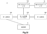
- FIG. 32 is an explanatory diagram illustrating an example of a schematic configuration of the system 4 according to the fourth embodiment.
- the system 4 includes a terminal device 11, a home base station 80A, a home base station 80B, a home base station gateway 1500, a first core network node 1600, and a second core network node 60.
- each of home base station 80A and home base station 80B may be simply referred to as home base station 80.
- the home base station 80 is an HNB
- the home base station gateway 1500 is an HNB-GW
- the first core network node 1600 is an SGSN.
- the home base station 80 may be a HeNB
- the home base station gateway 1500 may be a HeNB-GW
- the first core network node 1600 may be an MME.
- the terminal device 11 is a UE
- the second core network node 60 is an S-GW.
- the home base station 80A and the home base station 80B are provided with services by the home base station gateway 1500.
- the home base station communicating with the terminal device 11 can be changed from the home base station 80A to the home base station 80B.
- FIG. 33 is a block diagram illustrating an example of a schematic configuration of a home base station gateway 1500 according to the fourth embodiment.
- home base station gateway 1500 includes a communication processing unit 1501.
- the communication processing unit 1501 can be implemented by a processor or the like.
- home base station gateway 1500 (communication processing unit 1501) transmits a message including the address information and transport identification information of home base station 80B to first core network node 1200.
- a home access network specifically, a case of handover between home base stations that are serviced to the same home base station gateway
- information necessary for controlling a fixed broadband access network is obtained.
- the core network node can be acquired.
- communication quality of users of the 3GPP system can be maintained / improved, and the number of RABs accommodated for each base station can be optimized.
- FIG. 34 is a block diagram illustrating an example of a schematic configuration of the first core network node 1600 according to the fourth embodiment.
- the first core network node 1600 includes a communication processing unit 1601.
- the communication processing unit 1601 can be implemented by a processor or the like.
- the home base station that communicates with the terminal device 11 is changed from the home base station 80A to the home base station 80B.
- the first core network node 1600 receives from the home base station gateway 1500 a first message including the address information and transport identification information of the home base station 80B.
- the first core network node 1600 transmits a second message including the address information and the transport identification information to the second core network node 60.
- a home access network specifically, a case of handover between home base stations that are serviced to the same home base station gateway
- information necessary for controlling a fixed broadband access network is obtained.
- the core network node can be acquired.
- communication quality of users of the 3GPP system can be maintained / improved, and the number of RABs accommodated for each base station can be optimized.
- FIG. 35 is a sequence diagram illustrating an example of a schematic flow of a process according to the fourth embodiment.
- the home base station that communicates with the terminal device 11 is changed from the home base station 80A to the home base station 80B.
- the home base station gateway 1500 transmits a (first) message including the address information and transport identification information of the home base station 80B to the first core network node 1600.
- the first core network node 1600 receives the (first) message from the home base station gateway 1500.
- the first core network node 1600 transmits a second message including the address information and the transport identification information to the second core network node 60.
- FIG. 36 is an explanatory diagram illustrating an example of a schematic configuration of the system 5 according to the fifth embodiment.
- the system 5 includes a UE 10, a C-RAN (Centralized / Coordinated / Collaborative / Cloud Radio Access Network) 2100, an RRH (Remote Radio Head) 2200A, an RRH 2200B, an MME 2300, an S-GW 20, a P-GW 30, and a PCRF 40. And FBA50. Note that if it is not necessary to distinguish between RRH 2200A and RRH 2200B, each of RRH 2200A and RRH 2200B may be simply referred to as RRH 2200.
- RRH 2200A and RRH 2200B may be simply referred to as RRH 2200.
- RAN Radio Access Network
- C-RAN 2100 and RRH 2200 instead of eNB.
- the eNB is responsible for the processing of all layers of the RAN, but the C-RAN 2100 and the RRH 2200 are responsible for the processing of these layers.
- the RRH 2200 is responsible for lower layer processing (eg, layer 1)
- the C-RAN 2100 is responsible for upper layer processing (eg, layer 2 and layer 3).
- C-RAN 2100 and RRH 2200 communicate with UE 10.
- the C-RAN 2100 is connected to a plurality of RRHs 2200 (for example, RRH 2200A and RRH 2200B), and manages the plurality of RRHs 2200 in an integrated manner.
- layer 1/2 processing is performed when executing SON (Self-Organization Network), CoMP (Coordinated Multi Point) transmission / reception, CS (Centralized Scheduling) and / or eICIC (enhanced Inter-Cell Interference Coordination), etc. It can be done more effectively.
- the C-RAN 2100 communicates with the RRH 2200 via the FBA 50.
- PCRF40 and FBA50 operate
- the S-GW 20 and the P-GW 30 also operate in the same manner as in the first embodiment and / or the third embodiment.
- the UE 10 first communicates with the RRH 2200A. Thereafter, for example, as the UE 10 moves, the RRH communicating with the UE 10 is changed from the RRH 2200A to the RRH 2200B. That is, the handover of the UE 10 from the RRH 2200A to the RRH 2200B is performed.
- the C-RAN 2100 may be a first RAN node having another name
- the RRH 2200 may also be a second RAN node having another name
- the MME 2300 may also be a core network node (control plane node) having another name
- the S-GW 20 may also be a core network node (user plane node) having another name.
- FIG. 37 is a block diagram illustrating an example of a schematic configuration of a C-RAN 2100 according to the fifth embodiment.
- the C-RAN 2100 includes an RRH communication unit 2110, a network communication unit 2120, a storage unit 2130, and a processing unit 2149.
- the wireless communication unit 110 transmits a signal to the RRH 2200 and receives a signal from the RRH 2200.
- the network communication unit 2120 receives a signal from a network (for example, backhaul) and transmits the signal to the network.
- Storage unit 2130 The storage unit 2130 temporarily or permanently stores programs and parameters for the operation of the C-RAN 2100 and various data.
- the processing unit 2140 provides various functions of the C-RAN 2100.
- the processing unit 2140 includes a first communication processing unit 2141, a second communication processing unit 2143, and a generation unit 2145.
- the processing unit 2140 may further include other components other than these components. That is, the processing unit 140 can perform operations other than the operations of these components.
- the processing unit 2140 (first communication processing unit 2141) communicates with the RRH 2200 via the RRH communication unit 2110, and communicates with the UE 10 via the RRH 2200 (and the RRH communication unit 2110).
- the processing unit 2140 (second communication processing unit 2143) communicates with another network node (for example, the MME 2300) via the network communication unit 2120.
- Each of the RRH communication unit 2110 and the network communication unit 2120 may include a network adapter or a network interface card.
- the storage unit 2130 may include a memory (for example, a non-volatile memory and / or a volatile memory) and / or a hard disk.
- the processing unit 2140 may include a baseband (BB) processor and / or another processor.
- BB baseband
- the RRH communicating with the UE 10 is changed from the RRH 2200A to the RRH 2200B.
- the C-RAN 2100 (second communication processing unit 2143) transmits a message including the communication identification information of the RRH 2200B (that is, the target RRH) to the core network node (for example, the MME 2300).
- the C-RAN 2100 (generation unit 2145) generates the message.
- the C-RAN case specifically, the RRH change case
- communication quality of users of the 3GPP system can be maintained / improved, and the number of RABs accommodated for each base station can be optimized.
- the core network node is the MME 2300.
- the core network node may be a core network node having another name (control plane node).
- the communication identification information is an address and / or port number of the RRH 2200B.
- the C-RAN 2100 acquires the communication identification information via the CPRI interface (or another interface having an equivalent role).
- the communication identification information is information provided to the FBA 50. More specifically, for example, the communication identification information is information provided to the FBA 50 from the PCRF 40 (or another node that controls the FBA 50). Thereby, for example, bandwidth control can be performed.
- FIG. 38 is a block diagram illustrating an example of a schematic configuration of an MME 2300 according to the fifth embodiment.
- the MME 2300 includes a network communication unit 2310, a storage unit 2320, and a processing unit 2330.
- the network communication unit 2310 receives a signal from the network and transmits the signal to the network.
- Storage unit 2320 The storage unit 2320 temporarily or permanently stores programs and parameters for the operation of the MME 2300 and various data.
- Processing unit 2330 provides various functions of the MME 2300.
- the processing unit 2330 includes a communication processing unit 2331 and a generation unit 2333. Note that the processing unit 2330 may further include other components other than these components. That is, the processing unit 2330 can perform operations other than the operations of these components.
- the processing unit 2330 (communication processing unit 2331) communicates with other network nodes (C-RAN 2100, S-GW 20, etc.) via the network communication unit 2310.
- the network communication unit 2310 may include a network adapter or a network interface card.
- the storage unit 2320 may include a memory (for example, a nonvolatile memory and / or a volatile memory) and / or a hard disk.
- the processing unit 2330 may include a processor and the like.
- the RRH communicating with the UE 10 is changed from the RRH 2200A to the RRH 2200B.
- the MME 2300 receives a message including the communication identification information of the RRH 2200B (target RRH) from the C-RAN 2100.
- the MME 2300 transmits another message including the communication identification information to the core network node.
- the MME 2300 generation unit 2333) generates the other message.
- the C-RAN case specifically, the RRH change case
- communication quality of users of the 3GPP system can be maintained / improved, and the number of RABs accommodated for each base station can be optimized.
- (A) Core network node For example, the core network node is the S-GW 20.
- (B) Communication Identification Information The communication identification information is as described above in connection with the configuration example of the C-RAN 2100.
- FIG. 39 is a sequence diagram illustrating an example of a schematic flow of a process according to the fifth embodiment.
- the RRH that communicates with the UE 10 is changed from the RRH 2200A to the RRH 2200B.
- the C-RAN 2100 transmits a message including the communication identification information of the RRH 2200B to the MME 2300.
- the MME 2300 transmits another message including the communication identification information to another core network node (for example, the S-GW 20).
- another core network node for example, the S-GW 20.
- steps S435 to S453 may be performed.
- a network node (for example, C-RAN 2100, MME 2300, S-GW 20, P-GW 30 and / or PCRF 40) is not configured with individual hardware, but is configured as a VNF on a virtual machine. It may work with. That is, NFV may be used.
- a network node operating as a VFN on a virtual machine may be managed and organized by a function called MANO.
- the MANO that manages the VNF of the network node of the cellular network also manages the SDN controller that is a component of the FBA 50.
- the bandwidth control of the FBA 50 may be performed by the MANO instead of the PCRF 50 that is the VFN.
- Second Modification A function corresponding to the PCRF 40 may exist in the RAN.
- the RAN may perform control (for example, bandwidth control) of the fixed broadband access network (FBA 50).
- FBA 50 fixed broadband access network
- the C-RAN 2100 may transmit the message to a node having the above function instead of the MME 2300.
- the MME 2300 may transmit the other message to a node having the above function instead of the S-GW 20.
- Embodiments of the present invention are not limited to the first to fifth embodiments described above.
- the system may include a terminal device, a first wireless communication device, a second wireless communication device, a management device, and a core network node.
- the management device is a device corresponding to the first wireless communication device and the second wireless communication device, and may be capable of communicating with the core network node.
- the core network node may be a control plane node.
- the wireless communication device that communicates with the terminal device may be changed from the first wireless communication device to the second wireless communication device.
- the management device (communication processing unit) includes address information (for example, an IP address) and transport identification information (for example, a UDP port number) (or communication identification information) of the second wireless communication device.
- a message may be sent to the core network node.
- the management device (generation unit) may generate the message.
- the core network node may receive the message from the management device. Then, the core network node (communication processing unit) sends other messages including the address information (for example, IP address) and the transport identification information (for example, UDP port number) (or the communication identification information) to other To the other core network node (for example, a user plane node). For example, the core network node (generation unit) may generate the other message.
- the core network node may receive the message from the management device. Then, the core network node (communication processing unit) sends other messages including the address information (for example, IP address) and the transport identification information (for example, UDP port number) (or the communication identification information) to other To the other core network node (for example, a user plane node). For example, the core network node (generation unit) may generate the other message.
- each of the first wireless communication device and the second wireless communication device may be a base station that can operate as a secondary base station that provides additional wireless resources to the terminal device in dual connectivity.
- the management device may be a base station operable as a master base station corresponding to the secondary base station.
- the management apparatus may be a base station, and each of the first radio communication apparatus and the second radio communication apparatus uses an access technology that uses a radio access technology different from that of the base station. It may be a point.
- the access points (the first wireless communication device and the second wireless communication device) may be able to communicate with the terminal device with which the base station (the management device) communicates.
- each of the first wireless communication device and the second wireless communication device may be a home base station, and the management device provides a home base that provides services to the home base station. It may be a station gateway.
- the steps in the processing described in this specification do not necessarily have to be executed in time series in the order described in the sequence diagram.
- the steps in the processing may be executed in an order different from the order described as the sequence diagram or may be executed in parallel.
- At least one configuration of the base station described in this specification (for example, the eNB of the first embodiment, the base station or the wireless communication device of the second embodiment, or the C-RAN of the fifth embodiment)
- a base station apparatus for example, an apparatus including a BBU (Base Band Unit) or BBU) or a module for the base station apparatus (for example, a BBU or a BBU module)
- BBU Base Band Unit
- a module for the base station apparatus for example, a BBU or a BBU module
- other nodes described in this specification (MME of the first embodiment, wireless communication apparatus or first core network node of the second embodiment, HNB-GW or MME of the third embodiment, fourth A module comprising at least one component of the home base station gateway or first core network node of the embodiment or the MME of the fifth embodiment) may be provided.
- a method including processing of the at least one component may be provided, and a program for causing a processor to execute the processing of the at least one component may be provided.
- a recording medium in which the program is recorded may be provided.
- Appendix 2 The apparatus according to appendix 1, wherein the apparatus is the base station, a base station apparatus for the base station, or a module for the base station apparatus.
- Appendix 3 The apparatus according to appendix 1 or 2, wherein the core network node is an MME (Mobility Management Entity).
- MME Mobility Management Entity
- the wireless communication device is a secondary base station that provides additional wireless resources to a terminal device in dual connectivity,
- the base station is a master base station corresponding to the secondary base station,
- the apparatus according to any one of appendices 1 to 3.
- Appendix 5 The apparatus according to any one of appendices 1 to 4, wherein the first message is an S1AP: E-RAB MODIFICATION INDICATION message.
- the communication processing unit transmits the first message to the core network node even when there is no SCG (Secondary Cell Group) bearer for the terminal device and the first wireless communication device.
- SCG Secondary Cell Group
- Appendix 7 The apparatus according to any one of appendices 1 to 6, wherein the communication processing unit receives a second message including the address information and the transport identification information.
- Appendix 8 The apparatus according to any one of appendices 1 to 3, wherein the radio communication apparatus is an access point that uses a radio access technology different from that of the base station.
- Appendix 9 The apparatus according to appendix 8, wherein the wireless communication apparatus is a wireless local access network (WLAN) access point.
- WLAN wireless local access network
- the first wireless communication device is a first access point belonging to a first mobility set;
- the second wireless communication device is a second access point belonging to a second mobility set different from the first mobility set;
- An apparatus comprising: a communication processing unit that receives a first message including: from the base station.
- Appendix 12 The apparatus according to appendix 11, wherein the communication processing unit transmits a second message including the address information and the transport identification information to a core network node.
- Appendix 13 The apparatus according to appendix 12, wherein the apparatus is another core network node different from the core network node, or a module for the other core network node.
- Appendix 14 The apparatus according to appendix 13, wherein the other core network node is an MME.
- Appendix 15 The apparatus according to any one of appendices 12 to 14, wherein the core network node is an S-GW (Serving Gateway).
- S-GW Serving Gateway
- Appendix 16 The apparatus according to any one of appendices 12 to 15, wherein the second message is a MODIFY BEARER REQUEST message.
- a core network node that forwards the address information and the transport identification information to the base station, a message including address information and transport identification information of a wireless communication device capable of communicating with a terminal device with which the base station communicates, or the base
- An apparatus comprising: a communication processing unit that transmits to a station.
- the wireless communication device is another base station operable as a secondary base station that provides additional wireless resources to the terminal device in dual connectivity,
- Appendix 19 The apparatus according to appendix 18, wherein the apparatus is the other base station, a base station apparatus for the other base station, or a module for the base station apparatus.
- the communication processing unit transmits the message to the core network node, The apparatus according to any one of appendices 17 to 19, wherein the core network node is an MME.
- Appendix 21 The apparatus according to appendix 20, wherein the message is an S1AP: ENB CONFIGURATION TRANSFER message.
- Appendix 22 The apparatus according to appendix 20 or 21, wherein the core network node is a node that transmits an S1AP: MME CONFIGURATION TRANSFER message including the address information and the transport identification information to the base station.
- the communication processing unit transmits the message to the base station,
- the message is an X2AP: X2 SETUP REQUEST message or an X2AP: X2 SETUP RESPONSE message.
- the apparatus according to any one of appendices 17 to 19.
- the communication processing unit transmits the message to the base station,
- the message is an X2AP: SENB ADDITION REQUEST ACKNOWLEDGE message.
- the apparatus according to any one of appendices 17 to 19.
- Appendix 25 The apparatus according to appendix 17, wherein the radio communication apparatus is an access point that uses a radio access technology different from that of the base station.
- Appendix 26 The apparatus according to appendix 25, wherein the wireless communication apparatus is a wireless local access network (WLAN) access point.
- WLAN wireless local access network
- Appendix 27 The apparatus according to appendix 25 or 26, wherein the apparatus is the access point, a module for the access point, a termination apparatus corresponding to the access point, or a module for the termination apparatus.
- Appendix 29 29.
- Appendix 30 The apparatus according to appendix 28 or 29, wherein the core network node is an SGSN (Serving GPRS (General Packet Radio Service) Support Node).
- SGSN Serving GPRS (General Packet Radio Service) Support Node
- Appendix 31 The apparatus according to any one of appendices 28 to 30, wherein the message is a RANAP: RELOCATION COMPLETE message.
- Appendix 36 The apparatus according to any one of appendices 33 to 35, wherein the core network node is an S-GW.
- Appendix 38 The apparatus according to any one of appendices 1 to 37, wherein the address information is an IP (Internet Protocol) address.
- IP Internet Protocol
- Appendix 39 The apparatus according to appendix 38, wherein the IP address is a public IP address.
- Appendix 40 40.
- UDP User Datagram Protocol
- Appendix 42 The apparatus according to any one of appendices 1 to 41, wherein the address information and the transport identification information are information provided to a fixed broadband access network.
- Appendix 43 43.
- PCRF Policy and Charging Rules Function
- An apparatus comprising: a communication processing unit that receives a message including the address information and transport identification information of the second access point from the base station.
- a core network node that forwards the address information and the transport identification information to the base station, a message including address information and transport identification information of a wireless communication device capable of communicating with a terminal device with which the base station communicates, or the base Transmitting to a station.
- a core network node that forwards the address information and the transport identification information to the base station, a message including address information and transport identification information of a wireless communication device capable of communicating with a terminal device with which the base station communicates, or the base A program for causing a processor to execute transmission to a station.
- Appendix 56 A core network node that forwards the address information and the transport identification information to the base station, a message including address information and transport identification information of a wireless communication device capable of communicating with a terminal device with which the base station communicates, or the base A readable recording medium storing a program for causing a processor to execute transmission to a station.
- a core network node can acquire information necessary for controlling a fixed broadband access network.
Landscapes
- Engineering & Computer Science (AREA)
- Computer Networks & Wireless Communication (AREA)
- Signal Processing (AREA)
- Databases & Information Systems (AREA)
- Computer Security & Cryptography (AREA)
- Mobile Radio Communication Systems (AREA)
- Data Exchanges In Wide-Area Networks (AREA)
Priority Applications (9)
| Application Number | Priority Date | Filing Date | Title |
|---|---|---|---|
| KR1020187010949A KR102115683B1 (ko) | 2015-10-23 | 2016-09-26 | 고정 브로드밴드 액세스 네트워크의 제어에 관한 장치 |
| RU2018113693A RU2683958C1 (ru) | 2015-10-23 | 2016-09-26 | Устройство, относящееся к управлению сетью фиксированного широкополосного доступа |
| JP2017546463A JP6497444B2 (ja) | 2015-10-23 | 2016-09-26 | 固定ブロードバンドアクセスネットワークの制御に関連する装置 |
| MX2018004745A MX389632B (es) | 2015-10-23 | 2016-09-26 | Aparato relacionado con el control de red de acceso de banda ancha fija |
| US15/766,559 US10958573B2 (en) | 2015-10-23 | 2016-09-26 | Apparatus relating to control of fixed broadband access network |
| BR112018007762-3A BR112018007762B1 (pt) | 2015-10-23 | 2016-09-26 | eNB, MÉTODO DE UM eNB, MME E SeNB ALVO PARA CONTROLE DE REDE DE ACESSO DE BANDA LARGA FIXA |
| CN202310202364.7A CN116193524A (zh) | 2015-10-23 | 2016-09-26 | MeNB、MME和SeNB及其方法 |
| EP16857233.7A EP3367728B1 (en) | 2015-10-23 | 2016-09-26 | Device related to control of fixed broadband access network |
| CN201680061062.0A CN108141806A (zh) | 2015-10-23 | 2016-09-26 | 与固定宽带接入网络的控制相关的设备 |
Applications Claiming Priority (2)
| Application Number | Priority Date | Filing Date | Title |
|---|---|---|---|
| JP2015-208866 | 2015-10-23 | ||
| JP2015208866 | 2015-10-23 |
Publications (1)
| Publication Number | Publication Date |
|---|---|
| WO2017068915A1 true WO2017068915A1 (ja) | 2017-04-27 |
Family
ID=58557275
Family Applications (1)
| Application Number | Title | Priority Date | Filing Date |
|---|---|---|---|
| PCT/JP2016/078223 Ceased WO2017068915A1 (ja) | 2015-10-23 | 2016-09-26 | 固定ブロードバンドアクセスネットワークの制御に関連する装置 |
Country Status (9)
| Country | Link |
|---|---|
| US (1) | US10958573B2 (enExample) |
| EP (1) | EP3367728B1 (enExample) |
| JP (3) | JP6497444B2 (enExample) |
| KR (1) | KR102115683B1 (enExample) |
| CN (2) | CN108141806A (enExample) |
| MX (1) | MX389632B (enExample) |
| RU (3) | RU2704246C2 (enExample) |
| TW (2) | TWI718438B (enExample) |
| WO (1) | WO2017068915A1 (enExample) |
Families Citing this family (5)
| Publication number | Priority date | Publication date | Assignee | Title |
|---|---|---|---|---|
| WO2018220613A1 (en) * | 2017-05-28 | 2018-12-06 | Drivenets Ltd. | Provisioning of services in a communication network |
| CN110784918B (zh) | 2017-06-16 | 2021-01-29 | 华为技术有限公司 | 对上行链路传输的功率控制的方法和系统 |
| CN113383609A (zh) * | 2019-02-08 | 2021-09-10 | 株式会社Ntt都科摩 | 网络节点 |
| CN113491149A (zh) * | 2019-03-06 | 2021-10-08 | 株式会社Ntt都科摩 | 网络节点 |
| US11665077B2 (en) * | 2020-01-06 | 2023-05-30 | Zyxel Communications Corporation | Network device, speed test method therefor and speed test system |
Family Cites Families (18)
| Publication number | Priority date | Publication date | Assignee | Title |
|---|---|---|---|---|
| US20040203640A1 (en) * | 2002-05-10 | 2004-10-14 | Anders Molander | Providing RNC internet protocol address to circuit switched domain |
| US20090061877A1 (en) * | 2006-07-14 | 2009-03-05 | Gallagher Michael D | Generic Access to the Iu Interface |
| CN101115286A (zh) | 2006-07-26 | 2008-01-30 | 华为技术有限公司 | 一种基站到核心网的通信方法及系统 |
| CN102223691B (zh) * | 2010-04-15 | 2015-08-12 | 北京三星通信技术研究有限公司 | 移动通信系统中的切换方法 |
| JP2013526087A (ja) | 2010-04-16 | 2013-06-20 | パナソニック株式会社 | ローカルipネットワークに接続するueのハンドオーバ方法、ハンドオーバシステム、装置 |
| GB2488167A (en) | 2011-02-18 | 2012-08-22 | Nec Corp | Handover procedure in a home base station connected to a home base station gateway |
| GB201113942D0 (en) | 2011-08-12 | 2011-09-28 | Nec Corp | Communication system |
| US10390231B2 (en) * | 2013-05-29 | 2019-08-20 | Rivada Networks, Llc | Methods and systems for using location based service information to enable self-realized leases |
| CN104469869B (zh) | 2013-09-23 | 2019-08-13 | 中兴通讯股份有限公司 | 一种小小区切换方法和基站 |
| KR101685319B1 (ko) * | 2013-10-28 | 2016-12-09 | 엘지전자 주식회사 | 이종 네트워크에서 이중 연결 동작을 수행하기 위한 방법 및 장치 |
| EP3076746B1 (en) * | 2013-11-29 | 2019-04-17 | Fujitsu Connected Technologies Limited | Information interaction device, base station and communication system |
| EP2894903B1 (en) | 2014-01-13 | 2021-02-24 | Alcatel Lucent | Bearer offload in dual connectivity operation |
| WO2015108291A1 (en) | 2014-01-17 | 2015-07-23 | Lg Electronics Inc. | Bearer setup method and apparatus in wierless communication system supporting dual connectivity |
| JP2017513427A (ja) | 2014-03-13 | 2017-05-25 | インターデイジタル パテント ホールディングス インコーポレイテッド | ローカルオフロードおよびスモールセルアーキテクチャ(sca) |
| WO2015142078A1 (en) | 2014-03-19 | 2015-09-24 | Lg Electronics Inc. | Method and apparatus for transmitting information on serving gateway for supporting small cell mobility in wireless communication system |
| US10225779B2 (en) * | 2014-12-30 | 2019-03-05 | Lg Electronics Inc. | Method and apparatus for performing inter-MeNB handover without SeNB change in wireless communication system |
| US20160262059A1 (en) * | 2015-03-06 | 2016-09-08 | Luminate Wireless, Inc. | Methods and apparatus for transitioning a ue between base stations |
| KR101954495B1 (ko) * | 2015-09-23 | 2019-03-07 | 주식회사 케이티 | 단말의 이동성 제어 방법 및 그 장치 |
-
2016
- 2016-09-26 JP JP2017546463A patent/JP6497444B2/ja active Active
- 2016-09-26 RU RU2019108248A patent/RU2704246C2/ru active
- 2016-09-26 RU RU2018113693A patent/RU2683958C1/ru active
- 2016-09-26 MX MX2018004745A patent/MX389632B/es unknown
- 2016-09-26 CN CN201680061062.0A patent/CN108141806A/zh active Pending
- 2016-09-26 WO PCT/JP2016/078223 patent/WO2017068915A1/ja not_active Ceased
- 2016-09-26 CN CN202310202364.7A patent/CN116193524A/zh active Pending
- 2016-09-26 US US15/766,559 patent/US10958573B2/en active Active
- 2016-09-26 EP EP16857233.7A patent/EP3367728B1/en active Active
- 2016-09-26 KR KR1020187010949A patent/KR102115683B1/ko not_active Expired - Fee Related
- 2016-10-17 TW TW107140135A patent/TWI718438B/zh not_active IP Right Cessation
- 2016-10-17 TW TW105133365A patent/TWI683564B/zh not_active IP Right Cessation
-
2019
- 2019-03-13 JP JP2019045917A patent/JP6819710B2/ja active Active
- 2019-10-16 RU RU2019132814A patent/RU2714924C1/ru active
-
2020
- 2020-12-24 JP JP2020215088A patent/JP7147833B2/ja active Active
Non-Patent Citations (6)
| Title |
|---|
| "3rd Generation Partnership Project;Technical Specification Group Radio Access Network;Evolved Universal Terrestrial Radio Access (E-UTRA) and Evolved Universal Terrestrial Radio Access Network (E-UTRAN);Overall description;Stage 2(Release 13)", 3GPP TS 36.300 V13.1.0, September 2015 (2015-09-01), XP055377841 * |
| 3GPP TS 23.139 V12.2.0, March 2015 (2015-03-01) * |
| NEC: "BBF Signalling of Tunnel Information", 3GPP TSG-RAN WG3#76 R3-121131, 21 May 2012 (2012-05-21), XP050610990, Retrieved from the Internet <URL:http://www.3gpp.org/ftp/tsg_ran/WG3_Iu/TSGR3_76/Docs/R3-121131.zip> * |
| NOKIA NETWORKS: "Dual Connectivity enhancements with LIPA", 3GPP TSG-RAN WG3#89 R3- 151361, 24 August 2015 (2015-08-24), XP051006537, Retrieved from the Internet <URL:http://www.3gpp.org/ftp/tsg_ran/WG3_Iu/TSGR3_89/Docs/R3-151361.zip> * |
| SAMSUNG ET AL.: "Support of SIPTO and LIPA in dual connectivit y", 3GPP TSG-RAN WG3#89BIS R3-152018, 24 August 2015 (2015-08-24), XP051025938, Retrieved from the Internet <URL:http://www.3gpp.org/ftp/tsg_ran/WG3_Iu/TSGR3_89bis/Docs/R3-152018.zip> * |
| ZTE: "SIPTO/LIPA support in dual connectivity", 3GPP TSG-RAN WG3#89 R3-151512, 24 August 2015 (2015-08-24), XP051006677, Retrieved from the Internet <URL:http://www.3gpp.org/ftp/tsg_ran/WG3_Iu/TSGR3_89/Docs/R3-151512.zip> * |
Also Published As
| Publication number | Publication date |
|---|---|
| CN116193524A (zh) | 2023-05-30 |
| RU2019108248A (ru) | 2019-04-03 |
| TWI718438B (zh) | 2021-02-11 |
| EP3367728A4 (en) | 2019-05-01 |
| MX2018004745A (es) | 2018-08-01 |
| CN108141806A (zh) | 2018-06-08 |
| TWI683564B (zh) | 2020-01-21 |
| TW201720124A (zh) | 2017-06-01 |
| JP6819710B2 (ja) | 2021-01-27 |
| EP3367728A1 (en) | 2018-08-29 |
| RU2704246C2 (ru) | 2019-10-25 |
| MX389632B (es) | 2025-03-20 |
| RU2019108248A3 (enExample) | 2019-08-22 |
| EP3367728B1 (en) | 2024-05-01 |
| US20190068497A1 (en) | 2019-02-28 |
| KR20180055870A (ko) | 2018-05-25 |
| US10958573B2 (en) | 2021-03-23 |
| TW201907693A (zh) | 2019-02-16 |
| RU2683958C1 (ru) | 2019-04-03 |
| BR112018007762A2 (pt) | 2018-10-23 |
| JP7147833B2 (ja) | 2022-10-05 |
| KR102115683B1 (ko) | 2020-05-26 |
| JP2019115064A (ja) | 2019-07-11 |
| RU2714924C1 (ru) | 2020-02-21 |
| JPWO2017068915A1 (ja) | 2018-07-26 |
| JP6497444B2 (ja) | 2019-04-10 |
| JP2021052432A (ja) | 2021-04-01 |
Similar Documents
| Publication | Publication Date | Title |
|---|---|---|
| JP7147833B2 (ja) | 通信装置及び方法 | |
| CN106162771B (zh) | 一种小小区系统中不同MeNB间切换的方法及设备 | |
| JP6597686B2 (ja) | X2ゲートウェイ装置および方法 | |
| US9775073B2 (en) | Gateway configured to provide a handover, converting and routing function | |
| CN111182600B (zh) | 在无线通信系统中支持ue移动的方法及装置 | |
| US8532661B2 (en) | Network gateway configured to provide a handover, converting and routing function | |
| US9277456B2 (en) | Gateway device for handling UE context and a method thereof | |
| CN105009678A (zh) | 用于在多个e节点b和用户设备之间提供同时连接的方法和系统 | |
| KR20150104534A (ko) | 소형 셀 시스템에서 데이터 전달 방법 | |
| EP2836012A1 (en) | Method and system for setup or modification of data flows, primary node, secondary node, UE and computer program product | |
| CN102378145B (zh) | 切换方法、接入节点和宿主站点 | |
| KR101555648B1 (ko) | 펨토 기지국이 매크로 기지국과 x2 핸드오버 연동할 수 있도록 지원하기 위한 방법 및 이를 위한 펨토 게이트웨이 | |
| BR112018007762B1 (pt) | eNB, MÉTODO DE UM eNB, MME E SeNB ALVO PARA CONTROLE DE REDE DE ACESSO DE BANDA LARGA FIXA |
Legal Events
| Date | Code | Title | Description |
|---|---|---|---|
| 121 | Ep: the epo has been informed by wipo that ep was designated in this application |
Ref document number: 16857233 Country of ref document: EP Kind code of ref document: A1 |
|
| ENP | Entry into the national phase |
Ref document number: 2017546463 Country of ref document: JP Kind code of ref document: A |
|
| WWE | Wipo information: entry into national phase |
Ref document number: MX/A/2018/004745 Country of ref document: MX |
|
| ENP | Entry into the national phase |
Ref document number: 20187010949 Country of ref document: KR Kind code of ref document: A |
|
| NENP | Non-entry into the national phase |
Ref country code: DE |
|
| REG | Reference to national code |
Ref country code: BR Ref legal event code: B01A Ref document number: 112018007762 Country of ref document: BR |
|
| WWE | Wipo information: entry into national phase |
Ref document number: 2016857233 Country of ref document: EP Ref document number: 2018113693 Country of ref document: RU |
|
| ENP | Entry into the national phase |
Ref document number: 112018007762 Country of ref document: BR Kind code of ref document: A2 Effective date: 20180418 |