WO2017068915A1 - Device related to control of fixed broadband access network - Google Patents
Device related to control of fixed broadband access network Download PDFInfo
- Publication number
- WO2017068915A1 WO2017068915A1 PCT/JP2016/078223 JP2016078223W WO2017068915A1 WO 2017068915 A1 WO2017068915 A1 WO 2017068915A1 JP 2016078223 W JP2016078223 W JP 2016078223W WO 2017068915 A1 WO2017068915 A1 WO 2017068915A1
- Authority
- WO
- WIPO (PCT)
- Prior art keywords
- senb
- base station
- message
- address
- hnb
- Prior art date
Links
- 230000004048 modification Effects 0.000 claims description 64
- 238000012986 modification Methods 0.000 claims description 64
- 230000006854 communication Effects 0.000 abstract description 319
- 238000004891 communication Methods 0.000 abstract description 317
- 238000012545 processing Methods 0.000 abstract description 182
- 238000000034 method Methods 0.000 description 75
- 238000010586 diagram Methods 0.000 description 55
- 238000012546 transfer Methods 0.000 description 42
- 230000009977 dual effect Effects 0.000 description 27
- 230000006870 function Effects 0.000 description 25
- 230000008569 process Effects 0.000 description 25
- 230000004044 response Effects 0.000 description 20
- 230000008859 change Effects 0.000 description 17
- 238000005516 engineering process Methods 0.000 description 16
- 210000004027 cell Anatomy 0.000 description 14
- 210000004754 hybrid cell Anatomy 0.000 description 13
- 230000002776 aggregation Effects 0.000 description 10
- 238000004220 aggregation Methods 0.000 description 10
- 230000005540 biological transmission Effects 0.000 description 9
- 238000005457 optimization Methods 0.000 description 6
- 230000006872 improvement Effects 0.000 description 5
- 238000012423 maintenance Methods 0.000 description 5
- 230000001413 cellular effect Effects 0.000 description 3
- 230000000694 effects Effects 0.000 description 3
- 230000004308 accommodation Effects 0.000 description 2
- 238000012508 change request Methods 0.000 description 2
- 230000003247 decreasing effect Effects 0.000 description 1
- 230000007774 longterm Effects 0.000 description 1
- 238000010295 mobile communication Methods 0.000 description 1
- 230000011664 signaling Effects 0.000 description 1
- 239000013589 supplement Substances 0.000 description 1
- 238000013519 translation Methods 0.000 description 1
Images


Classifications
-
- H—ELECTRICITY
- H04—ELECTRIC COMMUNICATION TECHNIQUE
- H04L—TRANSMISSION OF DIGITAL INFORMATION, e.g. TELEGRAPHIC COMMUNICATION
- H04L45/00—Routing or path finding of packets in data switching networks
- H04L45/74—Address processing for routing
-
- H—ELECTRICITY
- H04—ELECTRIC COMMUNICATION TECHNIQUE
- H04L—TRANSMISSION OF DIGITAL INFORMATION, e.g. TELEGRAPHIC COMMUNICATION
- H04L61/00—Network arrangements, protocols or services for addressing or naming
- H04L61/50—Address allocation
- H04L61/5007—Internet protocol [IP] addresses
-
- H—ELECTRICITY
- H04—ELECTRIC COMMUNICATION TECHNIQUE
- H04L—TRANSMISSION OF DIGITAL INFORMATION, e.g. TELEGRAPHIC COMMUNICATION
- H04L69/00—Network arrangements, protocols or services independent of the application payload and not provided for in the other groups of this subclass
- H04L69/16—Implementation or adaptation of Internet protocol [IP], of transmission control protocol [TCP] or of user datagram protocol [UDP]
-
- H—ELECTRICITY
- H04—ELECTRIC COMMUNICATION TECHNIQUE
- H04W—WIRELESS COMMUNICATION NETWORKS
- H04W16/00—Network planning, e.g. coverage or traffic planning tools; Network deployment, e.g. resource partitioning or cells structures
- H04W16/24—Cell structures
- H04W16/32—Hierarchical cell structures
-
- H—ELECTRICITY
- H04—ELECTRIC COMMUNICATION TECHNIQUE
- H04W—WIRELESS COMMUNICATION NETWORKS
- H04W36/00—Hand-off or reselection arrangements
- H04W36/0005—Control or signalling for completing the hand-off
- H04W36/0055—Transmission or use of information for re-establishing the radio link
- H04W36/0069—Transmission or use of information for re-establishing the radio link in case of dual connectivity, e.g. decoupled uplink/downlink
-
- H—ELECTRICITY
- H04—ELECTRIC COMMUNICATION TECHNIQUE
- H04W—WIRELESS COMMUNICATION NETWORKS
- H04W72/00—Local resource management
- H04W72/04—Wireless resource allocation
-
- H—ELECTRICITY
- H04—ELECTRIC COMMUNICATION TECHNIQUE
- H04W—WIRELESS COMMUNICATION NETWORKS
- H04W8/00—Network data management
- H04W8/02—Processing of mobility data, e.g. registration information at HLR [Home Location Register] or VLR [Visitor Location Register]; Transfer of mobility data, e.g. between HLR, VLR or external networks
-
- H—ELECTRICITY
- H04—ELECTRIC COMMUNICATION TECHNIQUE
- H04W—WIRELESS COMMUNICATION NETWORKS
- H04W84/00—Network topologies
- H04W84/02—Hierarchically pre-organised networks, e.g. paging networks, cellular networks, WLAN [Wireless Local Area Network] or WLL [Wireless Local Loop]
- H04W84/10—Small scale networks; Flat hierarchical networks
- H04W84/16—WPBX [Wireless Private Branch Exchange]
-
- H—ELECTRICITY
- H04—ELECTRIC COMMUNICATION TECHNIQUE
- H04W—WIRELESS COMMUNICATION NETWORKS
- H04W92/00—Interfaces specially adapted for wireless communication networks
- H04W92/04—Interfaces between hierarchically different network devices
- H04W92/14—Interfaces between hierarchically different network devices between access point controllers and backbone network device
-
- H—ELECTRICITY
- H04—ELECTRIC COMMUNICATION TECHNIQUE
- H04W—WIRELESS COMMUNICATION NETWORKS
- H04W36/00—Hand-off or reselection arrangements
- H04W36/0005—Control or signalling for completing the hand-off
- H04W36/0055—Transmission or use of information for re-establishing the radio link
- H04W36/0077—Transmission or use of information for re-establishing the radio link of access information of target access point
-
- H—ELECTRICITY
- H04—ELECTRIC COMMUNICATION TECHNIQUE
- H04W—WIRELESS COMMUNICATION NETWORKS
- H04W88/00—Devices specially adapted for wireless communication networks, e.g. terminals, base stations or access point devices
- H04W88/08—Access point devices
Definitions
- the present invention relates to an apparatus related to control of a fixed broadband access (FBA) network.
- FBA fixed broadband access
- the PCRF Policy and Charging Rules Function
- P-GW Packet data
- Fixed broadband with the local IP address of the base station (ie, the outer IP address, public IP address, or global IP address of the IPsec tunnel) and UDP port number received from the network gateway (QoS) along with QoS (Quality of Service) information in the PCRF Send to access network.
- QoS Quality of Service
- the fixed broadband access network converts the QoS information into DSCP (Differentiated Service Code Point) and applies it to the line associated with the local IP address and the UDP port number received from the PCRF.
- DSCP Differentiated Service Code Point
- 3GPP system users Control the bandwidth for use.
- Non-Patent Document 1 (for example, FIG. 9.1.5 and FIG. 9.3.4-1) discloses processing as described above.
- Non-Patent Document 2 (for example, FIG. 5.7.2.1-1 and FIG. A.3-1) discloses a handover procedure in the home access network.
- Non-Patent Document 3 (for example, FIG. 10.1.2.8.4-1) discloses a procedure for changing the SeNB of dual connectivity.
- Non-Patent Document 4 and Non-Patent Document 5 disclose procedures when a hybrid cell is used.
- the IP address and UDP port of the target base station (for example, the target HNB (Home Node B) or the changed SeNB (Secondary evolved Node B))
- the number is not sent to the core network node.
- fixed broadband access network control for example, bandwidth control
- RAB Radio Access Bearer
- An object of the present invention is to enable a core network node to acquire information necessary for controlling, for example, a fixed broadband access network in more cases.
- the first device of the present invention changes the SeNB communicating with the terminal device from the source SeNB to the target SeNB, the first device transmits an E-RABRAMODIFICATION INDICATION message including address information and UDP port information to the core network node. .
- the second device of the present invention changes the SeNB communicating with the terminal device from the source SeNB to the target SeNB, the second device receives an E-RAB MODIFICATION INDICATION message including address information and UDP port information from the MeNB.
- the third device of the present invention After receiving SENB ADDITON REQUEST from MeNB, the third device of the present invention transmits SENB ADDITON REQUEST ACKNOWLEDGE including address information and UDP port information to MeNB.
- the fourth device of the present invention sends an E-RAB MODIFICATION INDICATION message containing the address information and the UDP port information to the core. Send to network node.
- the fifth device of the present invention After transmitting SENB ADDITON REQUEST to SeNB, the fifth device of the present invention receives SENB ADDITON REQUEST ACKNOWLEDGE including address information and UDP port information from SeNB.
- the sixth device of the present invention transmits an E-RAB MODIFICATIONSeINDICATION message including the local IP address of the target SeNB to the core network node.
- the core network node can acquire information necessary for controlling the fixed broadband access network.
- another effect may be show
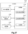
- System configuration example 6.2 Configuration example of home base station gateway 6.3. Configuration example of first core network node 6.4. Process flow Fifth embodiment 7.1. System configuration example 7.2. Configuration example of C-RAN 7.3. Configuration example of MME 7.4. Process flow 7.5. Modification 8 Other embodiments
- PCRF Policy and Charging Rules Function
- P-GW The local IP address of the base station (ie, the outer IP address of the IPsec tunnel) and the UDP port number received from the packet data network gateway) are transmitted to the fixed broadband access network together with QoS (Quality of Service) information in the PCRF.
- QoS Quality of Service
- the fixed broadband access network converts the QoS information into DSCP (Differentiated Service Code Point) and applies it to the line associated with the local IP address and the UDP port number received from the PCRF.
- DSCP Differentiated Service Code Point
- 3GPP system users Control the bandwidth for use.
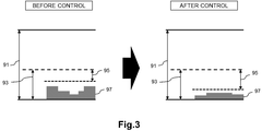
- FIGS. 1 to 3 are explanatory diagrams for explaining an example of band control. 1 to 3, a band 91, a band 93, a band 95, and a band 97 before and after band control are shown.
- the band 91 is the entire band of the line accommodating the base station used by the user of the 3GPP system.
- a band 93 is a band reserved for a base station used by a user of the 3GPP system.
- the band 95 is a band that can newly accept a user of the 3GPP system.
- the band 97 is a band that is actually used. For example, as shown in FIG. 1, the upper limit value of band 93 (band reserved for a base station used by a user of the 3GPP system) can be adjusted.
- the bandwidth 95 (band that can newly accept a user of the 3GPP system) can be reduced in a line where the number of users of the 3GPP system has increased.
- the bandwidth 95 (a bandwidth that can newly accept a 3GPP system user) can be increased.
- Such a band control technique is shown in 3GPP TS 23.139 V12.2.0.
- the base station newly accepts the upper limit value of the band 93 (band reserved for the base station used by the user of the 3GPP system) and / or the band 95 (user of the 3GPP system).
- admission control is also performed based on the available bandwidth.
- the admission control includes determining whether to accept a radio access bearer (RAB) of a UE (User Equipment) to be handed over. Thereby, the accommodation number of RAB for every base station can be optimized.
- RAB radio access bearer
- FIG. 4 is a sequence diagram for explaining a first example of a procedure for a fixed broadband access network.
- FIG. 4 is an example of a case where WCDMA (Wideband Code-Division Multiple Access) (registered trademark) is used as a communication method, and is FIG. 9.3.4-1 of 3GPP TS23.139 V12.2.0. .
- WCDMA Wideband Code-Division Multiple Access
- step 1 the target HNB sends the target HNB local IP address and UDP port number to the target SGSN (Serving GPRS (General Packet Radio Service) Support Node).
- target SGSN Serving GPRS (General Packet Radio Service) Support Node
- step 2a the target SGSN sends the target HNB local IP address and UDP port number to the S-GW (Serving Gateway), and in step 2b, the S-GW sends the target HNB local IP address and UDP port number to the P- Send to GW.
- S-GW Serving Gateway
- step 3 the P-GW sends the target HNB local IP address and UDP port number to the PCRF.
- step 4 the PCRF sends the target HNB local IP address and UDP port number to the fixed broadband access network.
- step 2a in FIG. 4 is executed when the following processing is executed in step 1.
- step 2a in FIG. 4 is executed when the following processing is executed in step 1.
- step 2a in FIG. 4 is executed when the following processing is executed in step 1.
- step 2a in FIG. 4 is executed when the following processing is executed in step 1.
- step 2a in FIG. 4 is executed when the following processing is executed in step 1.
- step 2a in FIG. 4 is executed when the following processing is executed in step 1.
- step 2a in FIG. 4 is executed when the following processing is executed in step 1.
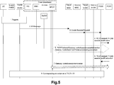
- FIG. 5 is a sequence diagram for explaining another example of the procedure for the fixed broadband access network.
- FIG. 5 is an example of a case where LTE (Long Term Evolution) is used as a communication method, which is FIG. 9.1.5 of 3GPP TS23.139 V12.2.0.
- LTE Long Term Evolution
- step 2 the target HeNB transmits the target HeNB local IP address and UDP port number to the MME.
- step 3 the MME transmits the target HeNB local IP address and UDP port number to the S-GW, and the S-GW transmits the target HeNB local IP address and UDP port number to the P-GW.
- step 4 the P-GW transmits the target HeNB local IP address and UDP port number to the PCRF.
- step 5 the PCRF transmits the target HeNB local IP address and UDP port number to the fixed broadband access network.
- step 2 in FIG. 5 is executed when the following processing is executed in step 1.
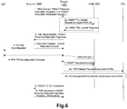
- FIG. 6 is an explanatory diagram for explaining a first example of a handover procedure in the home access network.
- FIG. 6 is FIG. 5.7.2.1-1 of 3GPP TS25.467 V12.3.0.
- the UE is handed over from the source HNB to the target HNB.
- HNB-GW Home Node B Gateway
- FIG. 7 is an explanatory diagram for explaining a second example of the handover procedure in the home access network.
- FIG. 7 is a diagram of FIG. 3-1.
- the UE is handed over from the source HNB to the target HNB.
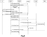
- FIG. 8 is an explanatory diagram for explaining an example of a SeNB change procedure.
- FIG. 8 is FIG. 10.1.2.8.4-1 of 3GPP TS36.300 V13.0.0.
- S-SeNB Source Secondary eNB
- T-SeNB Target Secondary eNB
- the MeNB sends an S1AP: E-RAB MODIFICATION INDICATION message to the MME. Send to.
- the MME requests Bearer Modification from the S-GW.
- the S1AP: E-RAB MODIFICATION INDICATION message does not include the local IP address and UDP port number of the T-SeNB, the MME confirms that the SCG bearer has moved from the S-SeNB to the T-SeNB. Cannot notify GW.
- the PCRF since the PCRF is not notified of the local IP address and UDP port number of the T-SeNB, the fixed broadband access network is not controlled (for example, bandwidth control). As a result, it may be impossible to maintain / improve communication quality of users of the 3GPP system and / or optimize the number of RABs accommodated for each base station.
- Step 10 is not executed. Therefore, similarly, maintenance / improvement of communication quality of users of the 3GPP system and / or optimization of the number of RABs accommodated for each base station may be impossible.
- Procedure for CSG 3GPP TS36.300 V13.0.0 stipulates that an eNB can configure a hybrid cell.
- a hybrid cell a user belonging to a CSG identified by an identifier called CSG ID uses the hybrid cell as a CSG cell, and a user who does not belong to the CSG uses the hybrid cell as a normal cell.
- the eNB that constitutes the hybrid cell decides whether to accept the UE to be handed over, and when to decide which bearer to accept and reject which bearer when accepting the UE to be handed over
- a user who uses a hybrid cell as a CSG cell may be favored over a user who uses a hybrid cell as a normal cell.
- SeNB configures a hybrid cell.
- the MeNB receives the CSG ID broadcast in the hybrid cell of the SeNB from the UE, and reports the CSG ID to the MME.
- MME determines whether UE uses the hybrid cell of SeNB as a CSG cell or a normal cell.
- 3GPP R3-1151949 and 3GPP R3-151995 disclose candidate determination procedures.
- the MeNB when the SCG bearer option is set in one of the bearer contexts in the SeNB, the MeNB includes the above CSG ID (the CSG ID broadcasted in the SeNB hybrid cell) S1AP: E -Send RAB MODIFICATION INDICATION message to MME.
- the MeNB sends an S1AP: UE CONTEXT MODIFICATION INDICATION message (including the CSG ID) ( A new message) is sent to the MME.
- the MeNB sends an S1AP: E-RAB MODIFICATION INDICATION message including the above CSG ID (CSG ID broadcasted in the SeNB hybrid cell) to the MME. To do.
- the message transmitted from the MeNB to the MME does not include the local IP address and UDP port number of the SeNB. Therefore, for example, bandwidth control of a fixed broadband access network is not performed. As a result, it may be impossible to maintain / improve communication quality of users of the 3GPP system and / or optimize the number of RABs accommodated for each base station.
- the PCRF of the 3GPP system receives the local IP address of the base station received from the P-GW (ie, the outer IP of the IPsec tunnel). Address, public IP address, or global IP address) and UDP port number are sent to the fixed broadband access network along with the QoS information in the PCRF.
- the fixed broadband access network converts the QoS information into DSCP, applies it to the line associated with the local IP address received from the PCRF and the UDP port number, and controls the bandwidth for the user of the 3GPP system. Do.
- the local IP address and UDP port number are not transmitted to the core network node.
- the local IP address and UDP port number of the SeNB after the change are not transmitted to the core network.
- the local IP address and UDP port number of the target HNB are not transmitted to the core network.
- control of the fixed broadband access network for example, bandwidth control
- maintenance / improvement of communication quality of users of the 3GPP system and / or optimization of the number of RABs accommodated for each base station is achieved. Can be impossible.
- An object of an embodiment of the present invention is to enable a core network node to acquire information necessary for controlling, for example, a fixed broadband access network in more cases.
- the SeNB is changed from the source SeNB to the target SeNB.
- the MeNB transmits a message including address information (for example, an IP address) and transport identification information (for example, a UDP port number) of the target SeNB to the MME.
- the MME receives the message.
- the HNB communicating with the UE is changed from the source HNB to the target HNB.
- the HNB-GW transmits a message including the address information (eg, IP address) and transport identification information (eg, UDP port number) of the target HNB to the SGSN core network node. Then, for example, the SGSN receives the message.
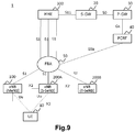
- FIG. 9 is an explanatory diagram illustrating an example of a schematic configuration of the system 1 according to the first embodiment.
- the system 1 includes a UE 10, an eNB 100, an eNB 200A, an eNB 200B, an MME 300, an S-GW 20, a P-GW 30, a PCRF 40, and an FBA (Fixed Broadband Access) 50.
- eNB 200A and eNB 200B may be simply referred to as eNB 200.
- UE10 supports dual connectivity and can communicate with MeNB and SeNB.
- eNB100 is eNB which can operate
- eNB200 is eNB which can operate
- the eNB 100 is an eNB (macro eNB) of a macro cell
- the eNB 200 is an eNB (small eNB) of a small cell (for example, a micro cell, a pico cell, or a femto cell).
- the eNB 200 is a home eNB. Note that the eNB 100 and the eNB 200 are not limited to this example.
- the eNB 100 operates as the MeNB for the UE 10
- the eNB 200A operates as the SeNB for the UE 10
- the UE 10 communicates with the eNB 100 (MeNB) and the eNB 200A (SeNB).
- the SeNB is changed from the eNB 200A (S-SeNB) to the eNB 200B (T-SeNB).
- the UE 10 comes to communicate with the eNB 100 (MeNB) and the eNB 200B (SeNB).
- the eNB 100 is connected to each of the eNB 200A and the eNB 200B via the X2 interface.
- An X2 gateway (X2GW) may exist between the eNB 100 and the eNB 200.
- X2GW X2 gateway
- each of eNB100, eNB200A, and eNB200B is connected with MME via S1 interface.
- the MME 300 is connected to the S-GW 20 via the S11 interface.
- the S-GW 20 is connected to the P-GW 30 via the S5 interface.
- the PCRF is a node for setting a policy in the network, connected to the P-GW 30 via the Gx interface, and connected to the FBA 50 via the S9a interface.
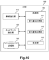
- FIG. 10 is a block diagram illustrating an example of a schematic configuration of the eNB 100 according to the first embodiment.
- the eNB 100 includes a radio communication unit 110, a network communication unit 120, a storage unit 130, and a processing unit 140.
- the wireless communication unit 110 transmits and receives signals wirelessly.
- the radio communication unit 110 receives a signal from the UE and transmits a signal to the UE.
- the network communication unit 120 receives a signal from a network (for example, backhaul) and transmits the signal to the network.
- a network for example, backhaul
- Storage unit 130 The storage unit 130 temporarily or permanently stores programs and parameters for the operation of the eNB 100 and various data.
- the processing unit 140 provides various functions of the eNB 100.
- the processing unit 140 includes a first communication processing unit 141, a second communication processing unit 143, and a generation unit 145.
- the processing unit 140 may further include other components other than these components. That is, the processing unit 140 can perform operations other than the operations of these components.
- the processing unit 140 (first communication processing unit 141) communicates with the UE via the wireless communication unit 110.
- the processing unit 140 (second communication processing unit 143) communicates with another network node (for example, eNB 200 or MME 300) via the network communication unit 120.
- another network node for example, eNB 200 or MME 300
- the wireless communication unit 110 may include an antenna and a radio frequency (RF) circuit.
- the network communication unit 120 may include a network adapter or a network interface card.
- the storage unit 130 may include a memory (for example, a nonvolatile memory and / or a volatile memory) and / or a hard disk.
- the processing unit 140 may include a baseband (BB) processor and / or another processor.
- BB baseband
- the SeNB for the UE 10 (that is, the SeNB that provides the UE 10 with additional radio resources in dual connectivity) is the eNB 200A (source SeNB) is changed to eNB 200B (target SeNB).
- the eNB 100 (second communication processing unit 143) transmits a first message including the address information and transport identification information of the eNB 200B (that is, the target SeNB) to the core network node.
- the eNB 100 (generating unit 145) generates the first message.
- (A) Core network node For example, the core network node is the MME 300.
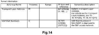
- the first message includes tunnel information including the address information and the transport identification information. More specifically, for example, the tunnel information is Tunnel Information for BBF IE.
- the Tunnel Information for BBF IE includes an IP address (address information) and a UDP port number (transport identification information).
- the first message is an S1AP: E-RAB MODIFICATION INDICATION message.
- the eNB 100 transmits an S1AP: E-RAB MODIFICATION INDICATION message to the core network node.
- the eNB 100 may perform S1AP: Send an E-RAB MODIFICATION INDICATION message to the core network node. This makes it possible to convey address information and transport identification information using the same message regardless of the presence or absence of the SCG bearer.
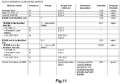
- FIG. 11 is an explanatory diagram for explaining an example of the S1AP: E-RAB MODIFICATION INDICATION message according to the first embodiment.
- information elements Information Elements: IE
- the S1AP: E-RAB MODIFICATION INDICATION message includes a Tunnel Information for BBF IE including an IP address (address information) and a UDP port number (transport identification information).
- eNB 100 When there is no SCG bearer for UE 10 and eNB 200A (S-SeNB) (that is, when there is only a split bearer), eNB 100 (second communication processing unit 143) sends other types of messages to the core You may transmit to a network node.
- S-SeNB S-SeNB
- the first message transmitted by the eNB 100 may be another type of message.
- the eNB 100 (generating unit 145) may acquire the first message from another node instead of generating the first message by itself.
- the eNB 100 (second communication processing unit 143) receives the second message including the address information and the transport identification information.
- the second message is a message transmitted by the eNB 200. This point will be described later in connection with the eNB 200. Thereby, for example, the eNB 100 can know the address information and transport identification information of the eNB 200.
- the address information is identification information (address) of the network layer (of the OSI (Open System Interconnection) reference model) or the Internet layer (of TCP / IP (Transmission Control Protocol / Internet Protocol)).
- the address information is an IP address.
- the IP address is a public IP address (or a global IP address).
- the IP address is a public IP address assigned to the eNB 200B (ie, the target SeNB) by the BBF domain in a no-NAT (Network Address Translation) case, or an RG (Residential Gateway) that performs NAT (ie, NATed RG).
- the IP address can be referred to as a “local IP address” in the 3GPP specifications.
- the transport identification information is identification information of a transport layer (OSI reference model or TCP / IP).
- the transport identification information is a UDP port number.
- the address information and the transport identification information are information provided to the FBA 50. More specifically, for example, the address information and the transport identification information are information provided from the PCRF 40 to the FBA 50. Thereby, for example, bandwidth control can be performed.
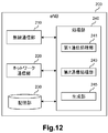
- FIG. 12 is a block diagram illustrating an example of a schematic configuration of the eNB 200 according to the first embodiment.
- the eNB 200 includes a radio communication unit 210, a network communication unit 220, a storage unit 230, and a processing unit 240.
- the wireless communication unit 210 transmits and receives signals wirelessly.
- the radio communication unit 210 receives a signal from the UE and transmits a signal to the UE.
- the network communication unit 220 receives a signal from a network (for example, backhaul) and transmits the signal to the network.
- a network for example, backhaul
- Storage unit 230 The storage unit 230 temporarily or permanently stores programs and parameters for the operation of the eNB 200 and various data.
- the processing unit 240 provides various functions of the eNB 200.
- the processing unit 240 includes a first communication processing unit 241, a second communication processing unit 243, and a generation unit 245. Note that the processing unit 240 may further include other components other than these components. That is, the processing unit 240 can perform operations other than the operations of these components.
- the processing unit 240 (first communication processing unit 241) communicates with the UE via the wireless communication unit 210.
- the processing unit 240 (second communication processing unit 243) communicates with other network nodes (for example, the eNB 100 or the MME 300) via the network communication unit 220.
- the wireless communication unit 210 may include an antenna, a radio frequency (RF) circuit, and the like.
- the network communication unit 220 may include a network adapter or a network interface card.
- the storage unit 230 may include a memory (for example, a nonvolatile memory and / or a volatile memory) and / or a hard disk.
- the processing unit 240 may include a baseband (BB) processor and / or another processor.
- BB baseband
- the eNB 200 can operate as a SeNB (that is, a SeNB that provides additional radio resources to the UE 10 in dual connectivity), and the eNB 100 can operate as a MeNB.
- the eNB 200 (second communication processing unit 243) transmits a message including the address information and transport identification information of the eNB 200 to the core network node that forwards the address information and the transport identification information to the eNB 100, or to the eNB 100.
- the eNB 200 (generating unit 245) generates the message.
- the eNB 100 can know the address information and transport identification information of the eNB 200.
- the fixed broadband access network can be controlled even in the case of dual connectivity (specifically, the case of SeNB change).
- the message includes tunnel information including the address information and the transport identification information. More specifically, for example, the tunnel information is Tunnel Information for BBF IE.
- the Tunnel Information for BBF IE includes an IP address (address information) and a UDP port number (transport identification information).
- the eNB 200 (second communication processing unit 243) transmits the message to the core network node.
- the core network node is the MME 300.
- the message is an S1AP: ENB CONFIGURATION TRANSFER message.
- the core network node MME 300 is a node that transmits to the eNB 100 an S1AP: MME CONFIGURATION TRANSFER message including the address information (IP address) and the transport identification information (UDP port number).
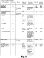
- S1AP ENB CONFIGURATION TRANSFER message and S1AP: MME CONFIGURATION TRANSFER message include SON Configuration Transfer In IE, SON Configuration Transfer In IE, and SON Configuration Transfer In IE.
- the X2 TNL Configuration Info IE includes the information elements as shown in FIG. 13, and particularly includes the Tunnel Information for BBF IE.
- Tunnel Information for BBF IE includes information elements as shown in FIG.
- the Tunnel Information for BBF IE includes a transport layer address and a UDP port number.
- the transport layer address is an IP address.
- the eNB 200 (second communication processing unit 243) transmits the message to the eNB 100.
- eNB200 (2nd communication process part 243) may transmit the said message to eNB100 directly, or may transmit the said message to eNB100 via X2GW.
- the message is an X2AP: X2 SETUP REQUEST message or an X2AP: X2 SETUP RESPONSE message.
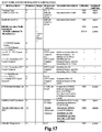
- the X2AP: X2 SETUP REQUEST message includes an information element as shown in FIG. 15, and in particular includes a Tunnel Information for BBF IE.
- Tunnel Information for BBF IE includes information elements as shown in FIG. That is, the Tunnel Information for BBF IE includes a transport layer address (that is, an IP address) and a UDP port number.
- the X2AP: X2 SETUP RESPONSE message includes an information element as shown in FIG. 16, and in particular includes a Tunnel Information for BBF IE.
- Tunnel Information for BBF IE includes information elements as shown in FIG. That is, the Tunnel Information for BBF IE includes a transport layer address (that is, an IP address) and a UDP port number.
- the eNB 200 may transmit the message to the eNB 100 as in the second example.
- eNB200 (2nd communication process part 243) may transmit the said message directly to eNB100, or may transmit the said message to eNB100 via X2 gateway (X2GW).
- X2GW X2 gateway
- the message may be an X2AP: SENB ADDITION REQUEST ACKNOWLEDGE message. That is, the eNB 200B (second communication processing unit 243) may transmit the message when the SeNB is changed from the eNB 200A (source SeNB) to the eNB 200B (target SeNB).
- the X2AP: SENB ADDITION REQUEST ACKNOWLEDGE message may include an information element as shown in FIG. 17, and in particular, may include Tunnel Information for BBF IE. Furthermore, the Tunnel Information for BBF IE may include information elements as shown in FIG. That is, the Tunnel Information for BBF IE may include a transport layer address (that is, an IP address) and a UDP port number.
- the said message transmitted by eNB200 is not limited to this example.
- the message transmitted by the eNB 200 may be another type of message.
- the address information is an IP address
- the transport identification information is a UDP port number.
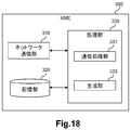
- FIG. 18 is a block diagram illustrating an example of a schematic configuration of the MME 300 according to the first embodiment.
- the MME 300 includes a network communication unit 310, a storage unit 320, and a processing unit 330.
- Network communication unit 310 The network communication unit 310 receives a signal from the network and transmits the signal to the network.
- Storage unit 320 The storage unit 320 temporarily or permanently stores programs and parameters for the operation of the MME 300 and various data.
- Processing unit 330 provides various functions of the MME 300.
- the processing unit 330 includes a communication processing unit 331 and a generation unit 333. Note that the processing unit 330 may further include other components other than these components. That is, the processing unit 330 can perform operations other than the operations of these components.
- the processing unit 330 communicates with the eNB via the network communication unit 310.
- the network communication unit 310 may include a network adapter or a network interface card.
- the storage unit 320 may include a memory (for example, a nonvolatile memory and / or a volatile memory) and / or a hard disk.
- the processing unit 330 may include a processor or the like.
- the SeNB for the UE 10 (that is, the SeNB that provides the UE 10 with additional radio resources in dual connectivity) becomes the eNB 200A (source SeNB).
- eNB200B target SeNB.
- the MME 300 receives a first message including the address information and transport identification information of the eNB 200B (target SeNB) from the eNB 100 (MeNB).
- the MME 300 transmits a second message including the address information and the transport identification information to the core network node.
- the MME 300 (generation unit 333) generates the second message.
- (A) Core network node For example, the core network node is the S-GW 20.
- the second message transmitted to the core network node is, for example, a MODIFY BEARER REQUEST message.
- the second message transmitted by the MME 300 is not limited to this example.
- the second message transmitted by the MME 300 may be another type of message.
- the address information is an IP address
- the transport identification information is a UDP port number.
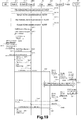
- FIG. 19 is a sequence diagram illustrating an example of a schematic flow of processing according to the first embodiment.
- the SeNB for the UE 10 is changed from the eNB 200A (source SeNB) to the eNB 200B (target SeNB). Therefore, here, the eNB 100, the eNB 200A, and the eNB 200B are denoted as the MeNB 100, the S-SeNB 200A, and the T-SeNB 200B, respectively.
- an X2 link is established between eNBs.
- an X2 link is established between the MeNB 100 and the T-SeNB 200B.
- the X2 link is established directly between eNBs or indirectly via X2GW.
- the X2 link can be established manually by the operator.
- the X2 link can be automatically established by SON (Self-Organization Network) defined in Chapter 22 of 3GPP TS36.300.
- SON is an automatic network optimization algorithm.
- both the MeNB 100 and the T-SeNB 200B can start the process of establishing the X2 link, but here, the MeNB 100 starts the process.
- the X2 link between the MeNB 100 and the S-SeNB 200A and the X2 link between the S-SeNB 200A and the T-SeNB 200B are also established by any of the four methods described above, but the description is omitted here. To do.
- the MeNB 100 transmits an S1AP: ENB CONFIGURATION TRANSFER message defined in 3GPP TS36.413 V13.0.0 to the MME 300.
- S1AP: The ENB CONFIGURATION TRANSFER message includes a SON Configuration Transfer IE, and the SON Configuration Transfer IE includes an X2 TNL Configuration Info IE (see FIG. 13). Further, the X2 TNL Configuration Info IE includes a Tunnel Information for BBF IE (see FIG. 14).
- Tunnel Information for BBF IE includes a local IP address (that is, a public IP address or a global IP address) of the MeNB 100 and a UDP port number.
- the MME 300 transmits the S1AP: MME CONFIGURATION TRANSFER message to the T-SeNB 200B.
- the S1AP: MME CONFIGURATION TRANSFER message includes the SON Configuration Transfer IE included in the S1AP: ENB CONFIGURATION TRANSFER message. That is, the SON Configuration Transfer IE is transmitted from the MeNB 100 to the T-SeNB 200B via the MME 300. Accordingly, the T-SeNB 200B can know the local IP address and UDP port number of the MeNB 100.
- the T-SeNB 200B transmits an S1AP: ENB CONFIGURATION TRANSFER message to the MME 300.
- the S1AP: ENB CONFIGURATION TRANSFER message includes the information element (IE) as described above, but here includes the local IP address and UDP port number of the T-SeNB.
- IE information element
- the MME 300 transmits the S1AP: MME CONFIGURATION TRANSFER message to the MeNB 100 in response to the reception of the S1AP: ENB CONFIGURATION TRANSFER message.
- the S1AP: MME CONFIGURATION TRANSFER message includes the SON Configuration Transfer IE included in the S1AP: ENB CONFIGURATION TRANSFER message. That is, the SON Configuration Transfer IE is transmitted from the T-SeNB 200B to the MeNB 100B via the MME 300.
- the MeNB 100 can know the local IP address and UDP port number of the T-SeNB 200B.
- the MeNB 100 uses the X2AP: X2 SETUP defined in 3GPP TS36.423 V13.0.0 based on the setting by the operator (for example, the setting of the local IP address and UDP port number of the T-SeNB 200B (as the destination)).
- a REQUEST message (see FIG. 15) is transmitted to the T-SeNB 200B.
- the X2AP: X2 SETUP REQUEST message includes the MeNB's local IP address and UDP port number. Accordingly, the T-SeNB 200B can know the local IP address and UDP port number of the MeNB 100.
- the T-SeNB 200B transmits an X2AP: X2 SETUP RESPONSE message (see FIG. 16) defined in 3GPP TS36.423 V13.0.0 to the MeNB 100.
- the X2AP: X2 SETUP RESPONSE message includes the local IP address and UDP port number of the T-SeNB 200B.
- the MeNB 100 can know the local IP address and UDP port number of the T-SeNB 200B.
- the T-SeNB 200B transmits an X2AP: X2 SETUP REQUEST message (see FIG. 15) to the MeNB 100, and the MeNB 100 sends an X2AP: X2 SETUP RESPONSE message (see FIG. 16) to the T. -You may transmit to SeNB200B.
- step S401C processing of the X2AP message between the MeNB 100 and the X2GW and processing of the X2AP message between the X2GW and the T-SeNB 200B (that is, 2.2.3.6.1 of 3GPP TS36.300 V13.0.0). Except for the processing added to the chapter procedure). Therefore, the overlapping description is omitted here.
- -S401D MeNB100 transmits X2AP: X2AP MESSAGE TRANSFER message defined in 3GPP TS36.423 V13.0.0 to X2GW (T-SeNB200B).
- the X2AP MESSAGE TRANSFER message includes an X2AP: X2 SETUP REQUEST message (see FIG. 15). That is, the MeNB 100 transmits an X2AP: X2 SETUP REQUEST message to the T-SeNB 200B via the X2GW.
- the X2AP: X2 SETUP REQUEST message includes the local IP address and UDP port number of the MeNB 100. Accordingly, the T-SeNB 200B can know the local IP address and UDP port number of the MeNB 100.
- T-SeNB 200B transmits the X2AP: X2AP MESSAGE TRANSFER message defined in 3GPP TS36.423 V13.0.0 to X2GW (MeNB100).
- the X2AP MESSAGE TRANSFER message includes an X2AP: X2 SETUP RESPONSE message (see FIG. 16). That is, the T-SeNB 200B transmits an X2AP: X2 SETUP RESPONSE message to the MeNB 100 via the X2GW.
- the X2AP: X2 SETUP RESPONSE message includes the local IP address and UDP port number of the T-SeNB 200B. As a result, the MeNB 100 can know the local IP address and UDP port number of the T-SeNB 200B.
- the T-SeNB 200B transmits an X2AP: X2 SETUP REQUEST message (see FIG. 15) to the MeNB 100, and the MeNB 100 sends an X2AP: X2 SETUP RESPONSE message (see FIG. 16) to the T. -You may transmit to SeNB200B.
- the dual connectivity of the UE 10 is started at any timing after the completion of step S401. More specifically, the UE 10 starts to communicate with both the MeNB 100 and the S-SeNB 200A.
- the MeNB 100 transmits an X2AP: SENB ADDITION REQUEST message to the T-SeNB 200B. Thereby, MeNB00 requests
- T-SeNB 200B transmits an X2AP: SENB ADDITION REQUEST ACKNOWLEDGE message to the MeNB 100. Thereby, T-SeNB200B notifies MeNB100 that the resource for UE10 was allocated.
- the X2AP: SENB ADDITION REQUEST ACKNOWLEDGE message may include an information element as shown in FIG. 17, and in particular, may include a Tunnel Information for BBF IE. Furthermore, the Tunnel Information for BBF IE may include information elements as shown in FIG. 17,
- the MeNB 100 transmits an X2AP: SENB RELEASE REQUEST message to the S-SeNB 200A. Thereby, the S-SeNB 200A releases resources for the UE 10.
- the MeNB 10 instructs the UE 10 to apply a new configuration.
- the MeNB 100 transmits an X2AP: SENB RECONFIGURATION COMPLETE message to the T-SeNB 200B. As a result, the MeNB 100 notifies the T-SeNB 200B of the success of the RRC connection reconfiguration procedure.
- S425-S429) Data is transferred from the S-SeNB 200A to the T-SeNB 200B.
- S431 When there is an SCG bearer When there is an SCG bearer for UE 10 and S-SeNB 200A (ie, when the SCG bearer option is set), the MeNB 100 sends an S1AP: E-RAB MODIFICATION INDICATION message (see FIG. 11). ) To the MME 300.
- E-RAB MODIFICATION INDICATION message includes Tunnel Information for BBF IE. Further, Tunnel Information for BBF IE includes the local IP address and UDP port number of T-SeNB 200B.
- MeNB100 Does not transmit the S1AP: E-RAB MODIFICATION INDICATION message to the MME 300.
- the MeNB 100 transmits an S1AP: E-RAB MODIFICATION INDICATION message to the MME 300.
- E-RAB MODIFICATION INDICATION message includes Tunnel Information for BBF IE. Further, Tunnel Information for BBF IE includes the local IP address and UDP port number of T-SeNB 200B.
- the MME 100 transmits a MODIFY BEARER REQUEST message to the S-GW 20 regardless of the presence or absence of the SCG bearer for the UE 10 and the S-SeNB 200A.
- the S-GW 20 updates the data path when there is the SCG bearer, and updates the data path when there is no SCG bearer (that is, when there is only the split bearer). Absent.
- the S-GW 20 transmits a Modify Bearer Request message (including the local IP address and UDP port number of the T-SeNB 200B) to the P-GW 30.
- the P-GW 30 transmits an IP-CAN session modification request message (including the local IP address and UDP port number of the T-SeNB 200B) to the PCRF 40.
- the PCRF 40 executes a Gateway control and QoS Rule provisioning procedure (including transmission and reception of the local IP address and UDP port number of the T-SeNB 200B) with the FBA 50.
- the FBA 50 applies the QoS information converted to DSCP to the line corresponding to the local IP address and UDP port number of the T-SeNB 200B received from the PCRF 40.
- the FBA 50 performs bandwidth control for the line to which the T-SeNB 200B is connected.
- the upper limit value of the band (band 93) reserved for the base station used by the user of the 3GPP system can be adjusted for the above line.
- a band (band 95) that can newly accept a user of the 3GPP system can be reduced for the above line.
- the PCRF 40 transmits an IP-CAN session modification Acknowledge message to the P-GW 30.
- the P-GW 30 transmits a Modify Bearer Response to the S-GW 20.
- the S-GW 20 transmits a Modify Bearer Response message to the MME 300.
- the MME 300 transmits an S1AP: E-RAB MODIFICATION CONFIRM message to the MeNB 100.
- the MeNB 100 transmits an X2AP: UE CONTEXT RELEASE message to the S-SeNB 200A. Thereby, the S-SeNB 200A releases the UE context.
- step S447 is executed after step S445, but step S447 may be executed at any timing after step S433.
- X2AP SETUP REQUEST message
- X2AP XEN SETUP REQUEST ACKNOWLEDGE R message s
- S1AP MME CONFIGURATION TRANSFER message
- S1AP E-RAB MODIFICATION INDICATION message
- these messages are merely examples, and other messages including an IP address and a UDP port number (for example, Tunnel Information for BBF IE) may be used.
- a network node (for example, eNB 100, eNB 200, MME 300, S-GW 20, P-GW 30 and / or PCRF 40) is not composed of individual hardware, but VNF (Virtualized Network Function ) As a virtual machine. That is, NFV (Network Function Virtualization) may be used. Network nodes operating as VFNs on virtual machines may be managed and organized by a function called MANO (Management and Orchestration).
- MANO Management and Orchestration
- an SDN (Software-Defined Network) controller in which the MANO that manages the VNF of a network node (for example, eNB 100, eNB 200, MME 300, S-GW 20, P-GW 30 and / or PCRF 40) of the cellular network is a component of the FBA Also manage.
- the bandwidth control of the FBA 50 may be performed by the MANO instead of the PCRF 50 that is the VFN.
- a function corresponding to the PCRF 40 may exist in a RAN (Radio Access Network).
- the RAN may perform control (for example, bandwidth control) of the fixed broadband access network (FBA 50).
- FBA 50 fixed broadband access network
- the eNB 100 may transmit the first message to a node having the above function instead of the MME 300.
- the MME 300 may transmit the second message to a node having the above function instead of the S-GW 20.
- 3GPP R2-153972 proposes LTE-WLAN (Wireless Local Area Network) aggregation (LWA).
- LWA Long Term Evolution
- the UE communicates using both LTE and WLAN.
- the eNB transmits data to the WLAN via the Xw interface.
- the same method as the above-described example of the first embodiment is also applied to the LWA case. May be. Thereby, it is possible to maintain / improve the communication quality of users of the 3GPP system and / or optimize the number of UEs accommodated for each base station.
- FIG. 20 is an explanatory diagram illustrating an example of a schematic configuration of a system according to a third modification of the first embodiment.
- the system includes eNB 100, WLAN Termination (WT) 201A, WT 201B, WLAN AP 203A, WLAN AP 203B, and MME 300. Further, the system includes UE 10, S-GW 20, P-GW 30, PCRF 40, and FBA 50.
- each of WT 201A and WT 201B may simply be referred to as WT 201.
- each of the WLAN AP 203A and the WLAN AP 203B can be simply referred to as the WLAN AP 203.
- the WT 201 terminates the Xw interface.
- the WLAN AP 203 belongs to a WLAN mobility set (that is, a set of one or more WLAN APs).
- the WLAN mobility set shares a common WT 201.
- the WLAN AP 203A belongs to the first WLAN mobility set, and the first WLAN mobility set shares the WT 201A.
- the WLAN AP 203B belongs to the second WLAN mobility set, and the second WLAN mobility set shares the WT 201B.
- the UE 10 supports LWA and can communicate with eNB 100 and WLAN AP 203.
- the UE 10 communicates with the eNB 100 and the WLAN AP 203A via LWA.
- the AP with which the UE 10 communicates is changed from the WLAN AP 203A (S-AP) to the WLAN AP 203B (T-AP).
- S-AP WLAN AP 203A
- T-AP WLAN AP 203B
- the WLAN AP that communicates with the UE 10 with which the eNB 100 communicates (that is, the WLAN AP for LTE-WLAN aggregation) is changed from the WLAN AP 203A to the WLAN AP 203B.
- the eNB 100 (second communication processing unit 143) transmits a first message including the address information and transport identification information of the WLAN AP 203B to the core network node (for example, the MME 300).
- the eNB 100 (generating unit 145) generates the first message.
- the MME 300 receives the first message from the eNB 100. Then, the MME 300 (communication processing unit 331) transmits a second message including the address information and the transport identification information to the core network node (for example, the S-GW 20). For example, the MME 300 (generation unit 333) generates the second message.
- the WLAN AP 203B (communication processing unit) transmits a third message including the address information and transport identification information of the WLAN AP 203B to the eNB 100 (for example, via the WT 201B).
- the WLAN AP 203B (generation unit) generates the third message.
- the WT 201B (communication processing unit) may transmit a third message including the address information and transport identification information of the WLAN AP 203B to the eNB 100.
- the WT 201B (generation unit) may generate the third message.
- the core network node can acquire information necessary for controlling the fixed broadband access network.
- communication quality of users of the 3GPP system can be maintained / improved, and the number of RABs accommodated for each base station can be optimized.
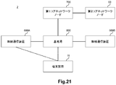
- FIG. 21 is an explanatory diagram illustrating an example of a schematic configuration of the system 2 according to the second embodiment.
- the system 2 includes a terminal device 11, a base station 500, a wireless communication device 600A, a wireless communication device 600B, a first core network node 700, and a second core network node 60. Note that when it is not necessary to distinguish between the wireless communication device 600A and the wireless communication device 600B, each of the wireless communication device 600A and the wireless communication device 600B may be simply referred to as the wireless communication device 600.
- the terminal device 11 is a UE
- the base station 500 is an eNB
- the first core network node 700 is an MME
- the second core network node 60 is an S-GW.
- the terminal device 11 can communicate with the base station 500 and the wireless communication device 600.
- the wireless communication device 600 can communicate with the terminal device 11 with which the base station 500 communicates.
- the wireless communication device communicating with the terminal device 11 with which the base station 500 communicates can be changed from the wireless communication device 600A to the wireless communication device 600B.
- the terminal device 11 supports dual connectivity.
- the wireless communication device 600 is a base station that can operate as a secondary base station that provides additional wireless resources to the terminal device 11 in dual connectivity.
- the radio communication device 600 is an eNB that can operate as a SeNB.
- the radio communication apparatus 600 is a home eNB, but is not limited to this example.
- the base station 500 can operate as a master base station corresponding to the secondary base station.
- the base station 500 is an eNB that can operate as a MeNB.
- the secondary base station for the terminal apparatus 11 can be changed from the wireless communication apparatus 600A to the wireless communication apparatus 600B.
- the terminal device 11 may support aggregation of different radio access technologies.
- the aggregation may be LTE-WLAN aggregation (LWA).
- the wireless communication device 600 may be an access point (AP) that uses a wireless access technology different from that of the base station 500.
- the wireless communication device 600 may be a WLAN AP.
- the wireless communication apparatus 600 may communicate with the base station 500 via WLAN Termination (WT).
- WT WLAN Termination
- the wireless communication device 600A may be a first AP belonging to the first mobility set, and the wireless communication device 600B is a second AP belonging to a second mobility set different from the first mobility set. There may be.
- the first mobility set may share a first WT and the second mobility set may share a second WT.
- the AP communicating with the terminal device 11 with which the base station 500 communicates may be changed from the wireless communication device 600A to the wireless communication device 600B.
- FIG. 22 is a block diagram illustrating an example of a schematic configuration of a base station 500 according to the second embodiment.
- the base station 500 includes a communication processing unit 503.
- the communication processing unit 503 can be implemented by a processor or the like.
- the wireless communication device that communicates with the terminal device 11 with which the base station 500 communicates is changed from the wireless communication device 600A to the wireless communication device 600B.
- base station 500 (communication processing unit 503) transmits a first message including address information and transport identification information of radio communication apparatus 600B to first core network node 700.
- the wireless communication device 600 is a base station that can operate as a secondary base station (for example, SeNB) that provides additional wireless resources to the terminal device 11 in dual connectivity.
- the base station 500 can operate as a master base station (for example, MeNB) corresponding to the secondary base station.
- the fixed broadband access network can be controlled.
- communication quality of users of the 3GPP system can be maintained / improved, and the number of RABs accommodated for each base station can be optimized.
- the wireless communication device 600 may be an AP (for example, WLAN AP) that uses a wireless access technology different from that of the base station 500.
- AP for example, WLAN AP
- the fixed broadband access network can also be controlled in such a case of aggregation of different radio access technologies (for example, LTE-WLAN aggregation) (for example, a case of changing WLAN AP).
- LTE-WLAN aggregation for example, a case of changing WLAN AP.
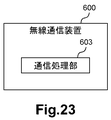
- FIG. 23 is a block diagram illustrating an example of a schematic configuration of a wireless communication apparatus 600 according to the second embodiment.
- the wireless communication device 600 includes a communication processing unit 603.
- the communication processing unit 603 can be implemented by a processor or the like.
- the wireless communication device 600 (communication processing unit 603) transmits a message including the address information and transport identification information of the wireless communication device 600 to the base station 500, for example.
- the wireless communication device 600 (communication processing unit 603) transmits the message to a core network node (for example, the first core network node 700) that transfers the address information and the transport identification information to the base station 500. May be.
- the base station 500 can know the address information and transport identification information of the wireless communication apparatus 600. As a result, control of the fixed broadband access network can be performed.
- the wireless communication device 600 is a base station that can operate as a secondary base station (for example, SeNB) that provides additional wireless resources to the terminal device 11 in dual connectivity.
- the base station 500 can operate as a master base station (for example, MeNB) corresponding to the secondary base station.
- the wireless communication device 600 may be an AP (for example, WLAN AP) that uses a wireless access technology different from that of the base station 500.
- AP for example, WLAN AP
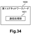
- FIG. 24 is a block diagram illustrating an example of a schematic configuration of the first core network node 700 according to the second embodiment.
- the first core network node 700 includes a communication processing unit 701.
- the communication processing unit 701 can be implemented by a processor or the like.
- the wireless communication device that communicates with the terminal device 11 with which the base station 500 communicates is changed from the wireless communication device 600A to the wireless communication device 600B.
- the first core network node 700 receives a first message including the address information and transport identification information of the wireless communication device 600B from the base station 500. Then, the first core network node 700 (communication processing unit 701) transmits a second message including the address information and the transport identification information to the second core network node 60.
- the wireless communication device 600 is a base station that can operate as a secondary base station (for example, SeNB) that provides additional wireless resources to the terminal device 11 in dual connectivity.
- the base station 500 can operate as a master base station (for example, MeNB) corresponding to the secondary base station.
- the fixed broadband access network can be controlled.
- communication quality of users of the 3GPP system can be maintained / improved, and the number of RABs accommodated for each base station can be optimized.
- the wireless communication device 600 may be an AP (for example, WLAN AP) that uses a wireless access technology different from that of the base station 500.
- AP for example, WLAN AP
- the fixed broadband access network can also be controlled in such a case of aggregation of different radio access technologies (for example, LTE-WLAN aggregation) (specifically, a case of changing an access point).
- LTE-WLAN aggregation for example, LTE-WLAN aggregation
- a case of changing an access point for example, LTE-WLAN aggregation
- communication quality of users of the 3GPP system can be maintained / improved, and the number of RABs accommodated for each base station can be optimized.
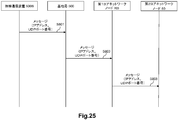
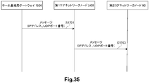
- FIG. 25 is a sequence diagram illustrating an example of a schematic flow of processing according to the second embodiment.
- Radio communication apparatus 600 transmits a message including address information and transport identification information of radio communication apparatus 600 to base station 500.
- the wireless communication device that communicates with the terminal device 11 with which the base station 500 communicates is changed from the wireless communication device 600A to the wireless communication device 600B.
- base station 500 transmits a first message including address information and transport identification information of radio communication apparatus 600B to first core network node 700.
- the first core network node 700 receives the first message from the base station 500.
- the first core network node 700 transmits a second message including the address information and the transport identification information to the second core network node 60.
- the wireless communication device 600 (for example, WLAN AP) transmits a message including the address information and transport identification information of the wireless communication device 600 to the base Transmit to station 500.
- a termination device for example, WT
- a message including port identification information may be transmitted to base station 500.
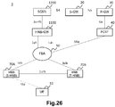
- FIG. 26 is an explanatory diagram illustrating an example of a schematic configuration of the system 3 according to the third embodiment.
- the system 3 includes UE 10, HNB 70A, HNB 70B, HNB-GW 1100, SGSN 1200, S-GW 20, P-GW 30, PCRF 40 and FBA 50.
- HNB 70A and HNB 70B may be simply referred to as HNB 70.
- the UE 10 communicates with SGSN 1200 via HNB 70 and HNB-GW 1100.
- the UE 10 communicates with the HNB 70A.
- the HNB communicating with the UE 10 is changed from the HNB 70A (S-HNB (Serving Home Node B)) to the HNB 70B (T-HNB (Target Home Node B)). That is, the handover of the UE 10 from the HNB 70A to the HNB 70B is performed.
- S-HNB Serving Home Node B
- T-HNB Target Home Node B
- the HNB 70 is connected to the HNB-GW 1100 via the FBA 50.
- the HNB 70 is connected to the HNB-GW 1100 via the Iuh interface.
- the HNB 70 is served by the HNB-GW 1100.
- the HNB 70A and the HNB 70B are connected to each other via the Iurh interface, and communicate directly via the Iurh interface when executing a handover (for example, as shown in FIGS. 6 and 7).
- the HNB 70A and HNB 70B may communicate indirectly via the HNB-GW 1100 when performing a handover (eg, as shown in FIGS. 6 and 7).
- the HNB-GW 1100 is connected to the SGSN 1200 via the Iu-PS interface.
- the SGSN 1200 is connected to the S-GW 20 via the S4 interface.
- the S-GW 20 is connected to the P-GW 30 via the S5 interface.
- the PCRF is a node for setting a policy in the network, connected to the P-GW 30 via the Gx interface, and connected to the FBA 50 via the S9a interface.
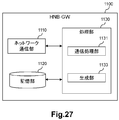
- FIG. 27 is a block diagram illustrating an example of a schematic configuration of the HNB-GW 1100 according to the third embodiment.
- the HNB-GW 1100 includes a network communication unit 1110, a storage unit 1120, and a processing unit 1130.
- the network communication unit 1110 receives a signal from the network and transmits the signal to the network.
- Storage unit 1120 The storage unit 1120 temporarily or permanently stores programs and parameters for the operation of the HNB-GW 1100 and various data.
- Processing unit 1130 provides various functions of the HNB-GW 1100.
- the processing unit 1130 includes a communication processing unit 1131 and a generation unit 1133. Note that the processing unit 1130 may further include other components other than these components. That is, the processing unit 1130 can perform operations other than the operations of these components.
- the processing unit 1130 communicates with other network nodes (for example, the HNB 70 and the SGSN 1200) via the network communication unit 1110.
- the network communication unit 1110 may include a network adapter or a network interface card.
- the storage unit 1120 may include a memory (for example, a nonvolatile memory and / or a volatile memory) and / or a hard disk.
- the processing unit 1130 may include a processor or the like.
- the HNB communicating with the UE 10 is changed from the HNB 70A to the HNB 70B.
- HNB-GW 1100 (communication processing unit 1131) transmits a message including the address information and transport identification information of HNB 70B to the core network node.
- the HNB-GW 1100 (generation unit 1133) generates the message.
- (A) Core network node For example, the said core network node is SGSN1200.
- the message includes tunnel information including the address information and the transport identification information. More specifically, for example, the tunnel information is Tunnel Information for BBF IE.
- the Tunnel Information for BBF IE includes an IP address (address information) and a UDP port number (transport identification information).
- the message is a RANAP: RELOCATION COMPLETE message.
- FIG. 28 is an explanatory diagram for explaining an example of a RANAP: RELOCATION COMPLETE message according to the third embodiment.
- an information element (IE) included in the RANAP: RELOCATION COMPLETE message is shown.
- the RANAP: RELOCATION COMPLETE message includes a Tunnel Information for BBF IE including an IP address (address information) and a UDP port number (transport identification information).
- the HNB-GW 1100 (generating unit 1133) may acquire the message from another node (for example, the HNB 70) instead of generating the message itself.
- the address information is identification information (address) of the network layer (of the OSI reference model) or the Internet layer (of TCP / IP).
- the address information is an IP address.
- the IP address is a public IP address (or a global IP address).
- the IP address is a public IP address assigned to HNB70B (ie, target HNB) by BBF domain in the no-NAT case, or RG that performs NAT (ie, , NATed RG), which is a public IP address assigned by the BBF domain and used for the HNB 70B.
- the IP address may be referred to as a “local IP address” or an “H (e) NB local IP address” in the 3GPP specifications.
- the transport identification information is identification information of a transport layer (OSI reference model or TCP / IP).
- the transport identification information is a UDP port number.
- the address information and the transport identification information are information provided to the FBA 50. More specifically, for example, the address information and the transport identification information are information provided from the PCRF 40 to the FBA 50. Thereby, for example, bandwidth control can be performed.
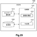
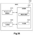
- FIG. 29 is a block diagram illustrating an example of a schematic configuration of an SGSN 1200 according to the third embodiment.
- the SGSN 1200 includes a network communication unit 1210, a storage unit 1220, and a processing unit 1230.
- the network communication unit 1210 receives a signal from the network and transmits the signal to the network.
- Storage unit 1220 The storage unit 1220 temporarily or permanently stores programs and parameters for the operation of the SGSN 1200 and various data.
- Processing unit 1230 provides various functions of the SGSN 1200.
- the processing unit 1230 includes a communication processing unit 1231 and a generation unit 1233. Note that the processing unit 1230 may further include other components other than these components. That is, the processing unit 1230 can perform operations other than the operations of these components.
- the processing unit 1230 communicates with other network nodes (for example, HNB-GW 1100 and S-GW 20) via the network communication unit 1210.
- the network communication unit 1210 may include a network adapter or a network interface card.
- the storage unit 1220 may include a memory (for example, a nonvolatile memory and / or a volatile memory) and / or a hard disk.
- the processing unit 1230 may include a processor or the like.
- the HNB communicating with the UE 10 is changed from the HNB 70A to the HNB 70B. That is, the handover of the UE 10 from the HNB 70A to the HNB 70B is performed.
- SGSN 1200 receives from HNB-GW 1100 a first message including the address information of HNB 70B and transport identification information.
- the SGSN 1200 transmits a second message including the address information and the transport identification information to the core network node.
- the SGSN 1200 (generation unit 1233) generates the second message.
- (A) Core network node For example, the core network node is the S-GW 20.
- the second message transmitted to the core network node is, for example, a MODIFY BEARER REQUEST message.
- the address information is an IP address
- the transport identification information is a UDP port number.
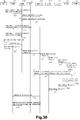
- FIG. 30 is a sequence diagram illustrating a first example of a schematic flow of a process according to the third embodiment.
- the first example is an example of a case where there is an Iurh interface between the HNB 70A and the HNB 70B.
- the UE 10 is communicating with the HNB 70A, but the HNB communicating with the UE 10 is changed from the HNB 70A to the HNB 70B. That is, the handover of the UE 10 from the HNB 70A to the HNB 70B is performed. Therefore, here, HNB 70A and HNB 70B are denoted as S-HNB 70A and T-HNB 70B, respectively. Note that RAB release does not occur after the handover.
- the S-HNB 70A confirms the access right of the UE 10. If the UE 10 has the access right, the S-HNB 70A transmits an RNA: CONNECT message (including an RNSAP: ENHANCED RELOCATION REQUEST message) to the T-HNB 70B.
- RNA: CONNECT message including an RNSAP: ENHANCED RELOCATION REQUEST message
- the T-HNB 70B transmits an HNBAP: TNL UPDATE REQUEST message to the HNB-GW 1100.
- HNBAP TNL UPDATE REQUEST message
- the transport network layer information related to the RAB transferred from the S-HNB 70A to the T-HNB 70B is updated.
- the HNB-GW 1100 transmits an HNBAP: TNL UPDATE RESPONSE message to the T-HNB 70B.
- the T-HNB 70B transmits an RNA: DIRECT TRANSFER message (including an RNSAP: ENHANCED RELOCATION RESPONSE message) to the S-HNB 70A.
- the T-HNB 70B notifies the S-HNB 70A that the UE 10 is ready for handover.
- the S-HNB 70A transmits an RNA: DIRECT TRANSFER message (including an RNSAP: RELOCATION COMMIT message). Thereby, the handover of the UE 10 to the T-HNB 70B is executed.
- the UE 10 transmits an RRC: RADIO BEARER RECONFIGRATION COMPLETE message to the T-HNB 70B. Thereby, the RRC Reconfiguration procedure is completed.
- the T-HNB 70B transmits an HNBAP: RELOCATION COMPLETE message to the HNB-GW 1100. Thereby, the T-HNB 70B notifies the HNB-GW 1100 that the handover of the UE 10 is successful. The HNB-GW 1100 switches the U-plane to the T-HNB 70B.
- the HNB-GW 1100 knows that the UE 10 has been handed over from the S-HNB 70A to the T-HNB 70B by receiving the HNBAP: RELOCATION COMPLETE message from the T-HNB 70B. Then, the HNB-GW 1100 transmits a RANAP: RELOCATION COMPLETE message (see FIG. 28) to the SGSN 1200.
- RELOCATION COMPLETE message includes Tunnel Information for BBF IE. Furthermore, Tunnel Information for BBF IE includes the local IP address and UDP port number of T-HNB70B.
- the SGSN sends a RANAP: RELOCATION COMMAND message to the S-HNB (ie, instructs the S-HNB to perform a handover), and then RANAP: RELOCATION A COMPLETE message is received from the T-HNB 70B. That is, the RANAP: RELOCATION COMPLETE message is transmitted and received during such a series of processes.
- the HNB-GW 1100 transmits to the RANAP: RELOCATION COMPLETE message SGSN 1200 without prior processing.
- the RANAP: RELOCATION COMPLETE message is merely an example, and other types of messages (for example, other types of RANAP messages) including the local IP address and UDP port number of the T-HNB 70B may be transmitted.
- the SGSN 1200 knows that the UE 10 has been handed over from the S-HNB 70A to the T-HNB 70B by receiving the RANAP: RELOCATION COMPLETE message (see FIG. 28) from the T-HNB 70B. SGSN 1200 obtains the local IP address and UDP port number of T-HNB 70B included in the RANAP RELOCATION COMPLETE message. Then, the SGSN 1200 transmits a Modify Bearer Request message including the IP address and the UDP port number to the S-GW 20.
- the SGSN sends a RANAP: RELOCATION COMMAND message to the S-HNB (ie, instructs the S-HNB to perform a handover), and then RANAP: RELOCATION A COMPLETE message is received from the T-HNB 70B.
- the SGSN 1200 receives the RANAP: RELOCATION COMPLETE message without transmitting the RANAP: RELOCATION COMMAND message, and transmits the Modify Bearer Request message.
- the S-GW 20 transmits a Modify Bearer Request message (including the local IP address of the T-HNB 70B and the UDP port number) to the P-GW 30.
- the P-GW 30 transmits an IP-CAN session modification request message (including the local IP address of the T-HNB 70B and the UDP port number) to the PCRF 40.
- the PCRF 40 executes a Gateway control and QoS Rule provisioning procedure (including transmission and reception of the local IP address and UDP port number of the T-SeNB 200B) with the FBA 50.
- the FBA 50 applies the QoS information converted to DSCP to the line corresponding to the local IP address and UDP port number of the T-SeNB 200B received from the PCRF 40.
- the FBA 50 performs bandwidth control for the line to which the T-SeNB 200B is connected.
- the upper limit value of the band (band 93) reserved for the base station used by the user of the 3GPP system can be adjusted for the above line.
- a band (band 95) that can newly accept a user of the 3GPP system can be reduced for the above line.
- the PCRF 40 transmits an IP-CAN session modification Acknowledge message to the P-GW 30.
- the P-GW 30 transmits a Modify Bearer Response to the S-GW 20.
- the S-GW 20 transmits a Modify Bearer Response message to the SGSN 1200.
- the HNB-GW 1100 transmits an HNBAP: UE-DEREGISTER message to the S-HNB 70A. As a result, the HNB-GW 1100 notifies the S-HNB 70A that the handover has succeeded.
- the S-HNB 70A transmits an RNA: DISCONNECT message (including an RNSAP: ENHANCED RELOCATION SIGNALING TRANSFER message) to the T-HNB 70B.
- step S1333 is executed after step S1331, but step S1333 may be executed at any timing after step S1315.
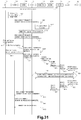
- FIG. 31 is a sequence diagram illustrating a second example of a schematic flow of a process according to the third embodiment.
- the second example is an example of the case where there is no Iurh interface between the HNB 70A and the HNB 70B.
- the UE 10 is communicating with the HNB 70A, but the HNB communicating with the UE 10 is changed from the HNB 70A to the HNB 70B. That is, the handover of the UE 10 from the HNB 70A to the HNB 70B is performed. Therefore, here, HNB 70A and HNB 70B are denoted as S-HNB 70A and T-HNB 70B, respectively. Note that RAB release does not occur after the handover.
- the UE 10 has established an active PS (Packet Switched) session with the SGSN 1200 via the S-HNB 70A and the HNB-GW 1100.
- PS Packet Switched
- the S-HNB 70A decides to move the UE 10 session to the T-HNB 70B.
- the S-HNB 70A transmits an RNA: DIRECT TRANSFER message (including a RANAP: RELOCATION REQUIRED message) to the HNB-GW 1100.
- the HNB-GW 1100 generates a RANAP: RELOCATION REQUEST message.
- the HNB-GW 1100 transmits a RANAP: RELOCATION REQUEST message to the T-HNB 70B.
- the T-HNB 70B allocates resources for handover. Thereafter, the T-HNB 70B transmits a RANAP: RELOCATION REQUEST ACKNOWLEDGE message.
- the HNB-GW 1100 transmits RUA: DIRECT TRANSFER (including RANAP: RELOCATION COMMAND) to the S-HNB 70A.
- the S-HNB 70A causes the UE 10 to execute Physical Channel Reconfiguration.
- the T-HNB 70B transmits an RUA: DIRECT TRANSFER message (including a RANAP: RELOCATION DETECT message) to the HNB-GW 1100.
- the T-HNB 70B transmits an RUA: DIRECT TRANSFER message (including a RANAP: RELOCATION COMPLETE message) to the HNB-GW 1100.
- the HNB-GW 1100 knows that the UE 10 has been handed over from the S-HNB 70A to the T-HNB 70B by receiving the RUA: DIRECT TRANSFER message from the T-HNB 70B. Then, the HNB-GW 1100 transmits a RANAP: RELOCATION COMPLETE message (see FIG. 28) to the SGSN 1200.
- step S1317 A more specific description of this step is the same as the description of step S1317 described above, for example. Therefore, the overlapping description is omitted here.
- the S-HNB 70A transmits RUA: DISCONNECT (RANAP: IU RELEASE COMPLETE message) to the HNB-GW 1100. As a result, the S-HNB 70A approves the Iu release procedure by the HNB-GW 1100.
- the HNB-GW 1100 transmits an HNBAP: UE DE-REGIGER message to the S-HNB 70A.
- the S-HNB 70A releases resources allocated to the UE 10 and deletes all context information associated with the UE 10.
- step S1439 is executed after step S1437, but step S1439 may be executed at any timing after step S1421.
- a network node (for example, HNB-GW1100, SGSN1200, S-GW20, P-GW30, and / or PCRF40) is not configured with individual hardware, but as a VNF on a virtual machine It may work with. That is, NFV may be used.
- a network node operating as a VFN on a virtual machine may be managed and organized by a function called MANO.
- the MANO that manages the VNF of the network node of the cellular network also manages the SDN controller that is a component of the FBA50.
- the bandwidth control of the FBA 50 may be performed by the MANO instead of the PCRF 50 that is the VFN.
- Second Modification A function corresponding to the PCRF 40 may exist in the RAN.
- the RAN may perform control (for example, bandwidth control) of the fixed broadband access network (FBA 50).
- FBA 50 fixed broadband access network
- the HNB-GW 1100 may transmit the (first) message to a node having the above function instead of the SGSN 1200.
- the SGSN 1200 may transmit the second message to a node having the above function instead of the S-GW 20.
- the system 3 according to the third embodiment includes the HNB 70, the HNB-GW 1100, and the SGSN 1200, but the third embodiment is included in this example. It is not limited.
- the system 3 may include a HeNB instead of the HNB 70, and the HeNB may perform the same operation as the above-described operation of the HNB 70.
- the system 3 may include the HeNB-GW instead of the HNB-GW 1100, and the HeNB-GW may perform the same operation as the above-described operation of the HNB-GW 1100.
- the system 3 may include an MME instead of the SGSN 1200, and the MME may perform the same operation as the above-described operation of the HSGSN 1200.
- the core network node can acquire information necessary for controlling the fixed broadband access network.
- FIG. 32 is an explanatory diagram illustrating an example of a schematic configuration of the system 4 according to the fourth embodiment.
- the system 4 includes a terminal device 11, a home base station 80A, a home base station 80B, a home base station gateway 1500, a first core network node 1600, and a second core network node 60.
- each of home base station 80A and home base station 80B may be simply referred to as home base station 80.
- the home base station 80 is an HNB
- the home base station gateway 1500 is an HNB-GW
- the first core network node 1600 is an SGSN.
- the home base station 80 may be a HeNB
- the home base station gateway 1500 may be a HeNB-GW
- the first core network node 1600 may be an MME.
- the terminal device 11 is a UE
- the second core network node 60 is an S-GW.
- the home base station 80A and the home base station 80B are provided with services by the home base station gateway 1500.
- the home base station communicating with the terminal device 11 can be changed from the home base station 80A to the home base station 80B.
- FIG. 33 is a block diagram illustrating an example of a schematic configuration of a home base station gateway 1500 according to the fourth embodiment.
- home base station gateway 1500 includes a communication processing unit 1501.
- the communication processing unit 1501 can be implemented by a processor or the like.
- home base station gateway 1500 (communication processing unit 1501) transmits a message including the address information and transport identification information of home base station 80B to first core network node 1200.
- a home access network specifically, a case of handover between home base stations that are serviced to the same home base station gateway
- information necessary for controlling a fixed broadband access network is obtained.
- the core network node can be acquired.
- communication quality of users of the 3GPP system can be maintained / improved, and the number of RABs accommodated for each base station can be optimized.
- FIG. 34 is a block diagram illustrating an example of a schematic configuration of the first core network node 1600 according to the fourth embodiment.
- the first core network node 1600 includes a communication processing unit 1601.
- the communication processing unit 1601 can be implemented by a processor or the like.
- the home base station that communicates with the terminal device 11 is changed from the home base station 80A to the home base station 80B.
- the first core network node 1600 receives from the home base station gateway 1500 a first message including the address information and transport identification information of the home base station 80B.
- the first core network node 1600 transmits a second message including the address information and the transport identification information to the second core network node 60.
- a home access network specifically, a case of handover between home base stations that are serviced to the same home base station gateway
- information necessary for controlling a fixed broadband access network is obtained.
- the core network node can be acquired.
- communication quality of users of the 3GPP system can be maintained / improved, and the number of RABs accommodated for each base station can be optimized.
- FIG. 35 is a sequence diagram illustrating an example of a schematic flow of a process according to the fourth embodiment.
- the home base station that communicates with the terminal device 11 is changed from the home base station 80A to the home base station 80B.
- the home base station gateway 1500 transmits a (first) message including the address information and transport identification information of the home base station 80B to the first core network node 1600.
- the first core network node 1600 receives the (first) message from the home base station gateway 1500.
- the first core network node 1600 transmits a second message including the address information and the transport identification information to the second core network node 60.
- FIG. 36 is an explanatory diagram illustrating an example of a schematic configuration of the system 5 according to the fifth embodiment.
- the system 5 includes a UE 10, a C-RAN (Centralized / Coordinated / Collaborative / Cloud Radio Access Network) 2100, an RRH (Remote Radio Head) 2200A, an RRH 2200B, an MME 2300, an S-GW 20, a P-GW 30, and a PCRF 40. And FBA50. Note that if it is not necessary to distinguish between RRH 2200A and RRH 2200B, each of RRH 2200A and RRH 2200B may be simply referred to as RRH 2200.
- RRH 2200A and RRH 2200B may be simply referred to as RRH 2200.
- RAN Radio Access Network
- C-RAN 2100 and RRH 2200 instead of eNB.
- the eNB is responsible for the processing of all layers of the RAN, but the C-RAN 2100 and the RRH 2200 are responsible for the processing of these layers.
- the RRH 2200 is responsible for lower layer processing (eg, layer 1)
- the C-RAN 2100 is responsible for upper layer processing (eg, layer 2 and layer 3).
- C-RAN 2100 and RRH 2200 communicate with UE 10.
- the C-RAN 2100 is connected to a plurality of RRHs 2200 (for example, RRH 2200A and RRH 2200B), and manages the plurality of RRHs 2200 in an integrated manner.
- layer 1/2 processing is performed when executing SON (Self-Organization Network), CoMP (Coordinated Multi Point) transmission / reception, CS (Centralized Scheduling) and / or eICIC (enhanced Inter-Cell Interference Coordination), etc. It can be done more effectively.
- the C-RAN 2100 communicates with the RRH 2200 via the FBA 50.
- PCRF40 and FBA50 operate
- the S-GW 20 and the P-GW 30 also operate in the same manner as in the first embodiment and / or the third embodiment.
- the UE 10 first communicates with the RRH 2200A. Thereafter, for example, as the UE 10 moves, the RRH communicating with the UE 10 is changed from the RRH 2200A to the RRH 2200B. That is, the handover of the UE 10 from the RRH 2200A to the RRH 2200B is performed.
- the C-RAN 2100 may be a first RAN node having another name
- the RRH 2200 may also be a second RAN node having another name
- the MME 2300 may also be a core network node (control plane node) having another name
- the S-GW 20 may also be a core network node (user plane node) having another name.
- FIG. 37 is a block diagram illustrating an example of a schematic configuration of a C-RAN 2100 according to the fifth embodiment.
- the C-RAN 2100 includes an RRH communication unit 2110, a network communication unit 2120, a storage unit 2130, and a processing unit 2149.
- the wireless communication unit 110 transmits a signal to the RRH 2200 and receives a signal from the RRH 2200.
- the network communication unit 2120 receives a signal from a network (for example, backhaul) and transmits the signal to the network.
- Storage unit 2130 The storage unit 2130 temporarily or permanently stores programs and parameters for the operation of the C-RAN 2100 and various data.
- the processing unit 2140 provides various functions of the C-RAN 2100.
- the processing unit 2140 includes a first communication processing unit 2141, a second communication processing unit 2143, and a generation unit 2145.
- the processing unit 2140 may further include other components other than these components. That is, the processing unit 140 can perform operations other than the operations of these components.
- the processing unit 2140 (first communication processing unit 2141) communicates with the RRH 2200 via the RRH communication unit 2110, and communicates with the UE 10 via the RRH 2200 (and the RRH communication unit 2110).
- the processing unit 2140 (second communication processing unit 2143) communicates with another network node (for example, the MME 2300) via the network communication unit 2120.
- Each of the RRH communication unit 2110 and the network communication unit 2120 may include a network adapter or a network interface card.
- the storage unit 2130 may include a memory (for example, a non-volatile memory and / or a volatile memory) and / or a hard disk.
- the processing unit 2140 may include a baseband (BB) processor and / or another processor.
- BB baseband
- the RRH communicating with the UE 10 is changed from the RRH 2200A to the RRH 2200B.
- the C-RAN 2100 (second communication processing unit 2143) transmits a message including the communication identification information of the RRH 2200B (that is, the target RRH) to the core network node (for example, the MME 2300).
- the C-RAN 2100 (generation unit 2145) generates the message.
- the C-RAN case specifically, the RRH change case
- communication quality of users of the 3GPP system can be maintained / improved, and the number of RABs accommodated for each base station can be optimized.
- the core network node is the MME 2300.
- the core network node may be a core network node having another name (control plane node).
- the communication identification information is an address and / or port number of the RRH 2200B.
- the C-RAN 2100 acquires the communication identification information via the CPRI interface (or another interface having an equivalent role).
- the communication identification information is information provided to the FBA 50. More specifically, for example, the communication identification information is information provided to the FBA 50 from the PCRF 40 (or another node that controls the FBA 50). Thereby, for example, bandwidth control can be performed.
- FIG. 38 is a block diagram illustrating an example of a schematic configuration of an MME 2300 according to the fifth embodiment.
- the MME 2300 includes a network communication unit 2310, a storage unit 2320, and a processing unit 2330.
- the network communication unit 2310 receives a signal from the network and transmits the signal to the network.
- Storage unit 2320 The storage unit 2320 temporarily or permanently stores programs and parameters for the operation of the MME 2300 and various data.
- Processing unit 2330 provides various functions of the MME 2300.
- the processing unit 2330 includes a communication processing unit 2331 and a generation unit 2333. Note that the processing unit 2330 may further include other components other than these components. That is, the processing unit 2330 can perform operations other than the operations of these components.
- the processing unit 2330 (communication processing unit 2331) communicates with other network nodes (C-RAN 2100, S-GW 20, etc.) via the network communication unit 2310.
- the network communication unit 2310 may include a network adapter or a network interface card.
- the storage unit 2320 may include a memory (for example, a nonvolatile memory and / or a volatile memory) and / or a hard disk.
- the processing unit 2330 may include a processor and the like.
- the RRH communicating with the UE 10 is changed from the RRH 2200A to the RRH 2200B.
- the MME 2300 receives a message including the communication identification information of the RRH 2200B (target RRH) from the C-RAN 2100.
- the MME 2300 transmits another message including the communication identification information to the core network node.
- the MME 2300 generation unit 2333) generates the other message.
- the C-RAN case specifically, the RRH change case
- communication quality of users of the 3GPP system can be maintained / improved, and the number of RABs accommodated for each base station can be optimized.
- (A) Core network node For example, the core network node is the S-GW 20.
- (B) Communication Identification Information The communication identification information is as described above in connection with the configuration example of the C-RAN 2100.
- FIG. 39 is a sequence diagram illustrating an example of a schematic flow of a process according to the fifth embodiment.
- the RRH that communicates with the UE 10 is changed from the RRH 2200A to the RRH 2200B.
- the C-RAN 2100 transmits a message including the communication identification information of the RRH 2200B to the MME 2300.
- the MME 2300 transmits another message including the communication identification information to another core network node (for example, the S-GW 20).
- another core network node for example, the S-GW 20.
- steps S435 to S453 may be performed.
- a network node (for example, C-RAN 2100, MME 2300, S-GW 20, P-GW 30 and / or PCRF 40) is not configured with individual hardware, but is configured as a VNF on a virtual machine. It may work with. That is, NFV may be used.
- a network node operating as a VFN on a virtual machine may be managed and organized by a function called MANO.
- the MANO that manages the VNF of the network node of the cellular network also manages the SDN controller that is a component of the FBA 50.
- the bandwidth control of the FBA 50 may be performed by the MANO instead of the PCRF 50 that is the VFN.
- Second Modification A function corresponding to the PCRF 40 may exist in the RAN.
- the RAN may perform control (for example, bandwidth control) of the fixed broadband access network (FBA 50).
- FBA 50 fixed broadband access network
- the C-RAN 2100 may transmit the message to a node having the above function instead of the MME 2300.
- the MME 2300 may transmit the other message to a node having the above function instead of the S-GW 20.
- Embodiments of the present invention are not limited to the first to fifth embodiments described above.
- the system may include a terminal device, a first wireless communication device, a second wireless communication device, a management device, and a core network node.
- the management device is a device corresponding to the first wireless communication device and the second wireless communication device, and may be capable of communicating with the core network node.
- the core network node may be a control plane node.
- the wireless communication device that communicates with the terminal device may be changed from the first wireless communication device to the second wireless communication device.
- the management device (communication processing unit) includes address information (for example, an IP address) and transport identification information (for example, a UDP port number) (or communication identification information) of the second wireless communication device.
- a message may be sent to the core network node.
- the management device (generation unit) may generate the message.
- the core network node may receive the message from the management device. Then, the core network node (communication processing unit) sends other messages including the address information (for example, IP address) and the transport identification information (for example, UDP port number) (or the communication identification information) to other To the other core network node (for example, a user plane node). For example, the core network node (generation unit) may generate the other message.
- the core network node may receive the message from the management device. Then, the core network node (communication processing unit) sends other messages including the address information (for example, IP address) and the transport identification information (for example, UDP port number) (or the communication identification information) to other To the other core network node (for example, a user plane node). For example, the core network node (generation unit) may generate the other message.
- each of the first wireless communication device and the second wireless communication device may be a base station that can operate as a secondary base station that provides additional wireless resources to the terminal device in dual connectivity.
- the management device may be a base station operable as a master base station corresponding to the secondary base station.
- the management apparatus may be a base station, and each of the first radio communication apparatus and the second radio communication apparatus uses an access technology that uses a radio access technology different from that of the base station. It may be a point.
- the access points (the first wireless communication device and the second wireless communication device) may be able to communicate with the terminal device with which the base station (the management device) communicates.
- each of the first wireless communication device and the second wireless communication device may be a home base station, and the management device provides a home base that provides services to the home base station. It may be a station gateway.
- the steps in the processing described in this specification do not necessarily have to be executed in time series in the order described in the sequence diagram.
- the steps in the processing may be executed in an order different from the order described as the sequence diagram or may be executed in parallel.
- At least one configuration of the base station described in this specification (for example, the eNB of the first embodiment, the base station or the wireless communication device of the second embodiment, or the C-RAN of the fifth embodiment)
- a base station apparatus for example, an apparatus including a BBU (Base Band Unit) or BBU) or a module for the base station apparatus (for example, a BBU or a BBU module)
- BBU Base Band Unit
- a module for the base station apparatus for example, a BBU or a BBU module
- other nodes described in this specification (MME of the first embodiment, wireless communication apparatus or first core network node of the second embodiment, HNB-GW or MME of the third embodiment, fourth A module comprising at least one component of the home base station gateway or first core network node of the embodiment or the MME of the fifth embodiment) may be provided.
- a method including processing of the at least one component may be provided, and a program for causing a processor to execute the processing of the at least one component may be provided.
- a recording medium in which the program is recorded may be provided.
- Appendix 2 The apparatus according to appendix 1, wherein the apparatus is the base station, a base station apparatus for the base station, or a module for the base station apparatus.
- Appendix 3 The apparatus according to appendix 1 or 2, wherein the core network node is an MME (Mobility Management Entity).
- MME Mobility Management Entity
- the wireless communication device is a secondary base station that provides additional wireless resources to a terminal device in dual connectivity,
- the base station is a master base station corresponding to the secondary base station,
- the apparatus according to any one of appendices 1 to 3.
- Appendix 5 The apparatus according to any one of appendices 1 to 4, wherein the first message is an S1AP: E-RAB MODIFICATION INDICATION message.
- the communication processing unit transmits the first message to the core network node even when there is no SCG (Secondary Cell Group) bearer for the terminal device and the first wireless communication device.
- SCG Secondary Cell Group
- Appendix 7 The apparatus according to any one of appendices 1 to 6, wherein the communication processing unit receives a second message including the address information and the transport identification information.
- Appendix 8 The apparatus according to any one of appendices 1 to 3, wherein the radio communication apparatus is an access point that uses a radio access technology different from that of the base station.
- Appendix 9 The apparatus according to appendix 8, wherein the wireless communication apparatus is a wireless local access network (WLAN) access point.
- WLAN wireless local access network
- the first wireless communication device is a first access point belonging to a first mobility set;
- the second wireless communication device is a second access point belonging to a second mobility set different from the first mobility set;
- An apparatus comprising: a communication processing unit that receives a first message including: from the base station.
- Appendix 12 The apparatus according to appendix 11, wherein the communication processing unit transmits a second message including the address information and the transport identification information to a core network node.
- Appendix 13 The apparatus according to appendix 12, wherein the apparatus is another core network node different from the core network node, or a module for the other core network node.
- Appendix 14 The apparatus according to appendix 13, wherein the other core network node is an MME.
- Appendix 15 The apparatus according to any one of appendices 12 to 14, wherein the core network node is an S-GW (Serving Gateway).
- S-GW Serving Gateway
- Appendix 16 The apparatus according to any one of appendices 12 to 15, wherein the second message is a MODIFY BEARER REQUEST message.
- a core network node that forwards the address information and the transport identification information to the base station, a message including address information and transport identification information of a wireless communication device capable of communicating with a terminal device with which the base station communicates, or the base
- An apparatus comprising: a communication processing unit that transmits to a station.
- the wireless communication device is another base station operable as a secondary base station that provides additional wireless resources to the terminal device in dual connectivity,
- Appendix 19 The apparatus according to appendix 18, wherein the apparatus is the other base station, a base station apparatus for the other base station, or a module for the base station apparatus.
- the communication processing unit transmits the message to the core network node, The apparatus according to any one of appendices 17 to 19, wherein the core network node is an MME.
- Appendix 21 The apparatus according to appendix 20, wherein the message is an S1AP: ENB CONFIGURATION TRANSFER message.
- Appendix 22 The apparatus according to appendix 20 or 21, wherein the core network node is a node that transmits an S1AP: MME CONFIGURATION TRANSFER message including the address information and the transport identification information to the base station.
- the communication processing unit transmits the message to the base station,
- the message is an X2AP: X2 SETUP REQUEST message or an X2AP: X2 SETUP RESPONSE message.
- the apparatus according to any one of appendices 17 to 19.
- the communication processing unit transmits the message to the base station,
- the message is an X2AP: SENB ADDITION REQUEST ACKNOWLEDGE message.
- the apparatus according to any one of appendices 17 to 19.
- Appendix 25 The apparatus according to appendix 17, wherein the radio communication apparatus is an access point that uses a radio access technology different from that of the base station.
- Appendix 26 The apparatus according to appendix 25, wherein the wireless communication apparatus is a wireless local access network (WLAN) access point.
- WLAN wireless local access network
- Appendix 27 The apparatus according to appendix 25 or 26, wherein the apparatus is the access point, a module for the access point, a termination apparatus corresponding to the access point, or a module for the termination apparatus.
- Appendix 29 29.
- Appendix 30 The apparatus according to appendix 28 or 29, wherein the core network node is an SGSN (Serving GPRS (General Packet Radio Service) Support Node).
- SGSN Serving GPRS (General Packet Radio Service) Support Node
- Appendix 31 The apparatus according to any one of appendices 28 to 30, wherein the message is a RANAP: RELOCATION COMPLETE message.
- Appendix 36 The apparatus according to any one of appendices 33 to 35, wherein the core network node is an S-GW.
- Appendix 38 The apparatus according to any one of appendices 1 to 37, wherein the address information is an IP (Internet Protocol) address.
- IP Internet Protocol
- Appendix 39 The apparatus according to appendix 38, wherein the IP address is a public IP address.
- Appendix 40 40.
- UDP User Datagram Protocol
- Appendix 42 The apparatus according to any one of appendices 1 to 41, wherein the address information and the transport identification information are information provided to a fixed broadband access network.
- Appendix 43 43.
- PCRF Policy and Charging Rules Function
- An apparatus comprising: a communication processing unit that receives a message including the address information and transport identification information of the second access point from the base station.
- a core network node that forwards the address information and the transport identification information to the base station, a message including address information and transport identification information of a wireless communication device capable of communicating with a terminal device with which the base station communicates, or the base Transmitting to a station.
- a core network node that forwards the address information and the transport identification information to the base station, a message including address information and transport identification information of a wireless communication device capable of communicating with a terminal device with which the base station communicates, or the base A program for causing a processor to execute transmission to a station.
- Appendix 56 A core network node that forwards the address information and the transport identification information to the base station, a message including address information and transport identification information of a wireless communication device capable of communicating with a terminal device with which the base station communicates, or the base A readable recording medium storing a program for causing a processor to execute transmission to a station.
- a core network node can acquire information necessary for controlling a fixed broadband access network.
Abstract
Description
1.関連技術
2.本発明の実施形態の概要
3.第1の実施形態
3.1.システムの構成例
3.2.eNB(MeNB)の構成例
3.3.eNB(SeNB)の構成例
3.4.MMEの構成例
3.5.処理の流れ
3.6.変形例
4.第2の実施形態
4.1.システムの構成例
4.2.基地局の構成例
4.3.無線通信装置の構成例
4.4.第1コアネットワークノードの構成例
4.5.処理の流れ
4.6.変形例
5.第3の実施形態
5.1.システムの構成例
5.2.HNB-GWの構成例
5.3.SGSNの構成例
5.4.処理の流れ
5.5.変形例
6.第4の実施形態
6.1.システムの構成例
6.2.ホーム基地局ゲートウェイの構成例
6.3.第1コアネットワークノードの構成例
6.4.処理の流れ
7.第5の実施形態
7.1.システムの構成例
7.2.C-RANの構成例
7.3.MMEの構成例
7.4.処理の流れ
7.5.変形例
8.他の実施形態 The description will be made in the following order.
1.
図1~図8を参照して、本発明の実施形態に関連する技術として、固定ブロードバンドアクセスネットワークの制御、ホームアクセスネットワークにおけるハンドオーバの手続き、デュアルコネクティビティのSeNBの変更の手続き、及びCSG(Closed Subscriber Group)に関する手続きを説明する。 << 1. Related technology >>
Referring to FIGS. 1 to 8, as technologies related to the embodiment of the present invention, fixed broadband access network control, handover procedure in home access network, dual connectivity SeNB change procedure, and CSG (Closed Subscriber) Group).
3GPP(Third Generation Partnership Project)システムの構成要素を固定ブロードバンドアクセスネットワークが接続している場合に、3GPPシステムのPCRF(Policy and Charging Rules Function)は、P-GW(Packet data network Gateway)から受け取った基地局のローカルIPアドレス(即ち、IPsecトンネルのouter IPアドレス)及びUDPポート番号を、PCRF内のQoS(Quality of Service)情報とともに固定ブロードバンドアクセスネットワークへ送信する。 (1) Control of fixed broadband access network When fixed broadband access network is connected to the components of 3GPP (Third Generation Partnership Project) system, PCRF (Policy and Charging Rules Function) of 3GPP system is P-GW ( The local IP address of the base station (ie, the outer IP address of the IPsec tunnel) and the UDP port number received from the packet data network gateway) are transmitted to the fixed broadband access network together with QoS (Quality of Service) information in the PCRF.
図1~図3は、帯域制御の例を説明するための説明図である。図1~図3を参照すると、帯域制御前と帯域制御後の帯域91、帯域93、帯域95及び帯域97が示されている。帯域91は、3GPPシステムの利用者が使用している基地局を収容している回線の全帯域である。帯域93は、3GPPシステムの利用者が使用している基地局のために確保している帯域である。帯域95は、3GPPシステムの利用者を新たに受け入れ可能な帯域である。帯域97は、実際に使用されている帯域である。例えば、図1に示されるように、帯域93(3GPPシステムの利用者が使用している基地局のために確保している帯域)の上限値が調整され得る。例えば、図2に示されるように、3GPPシステムの利用者が増えた回線では、帯域95(3GPPシステムの利用者を新たに受け入れ可能な帯域)が減らされ得る。例えば、図3に示されるように、3GPPシステムの利用者が減った回線では、帯域95(3GPPシステムの利用者を新たに受け入れ可能な帯域)が増やされ得る。このような帯域制御の手法が、3GPP TS23.139 V12.2.0に示されている。 Example of Band Control FIGS. 1 to 3 are explanatory diagrams for explaining an example of band control. 1 to 3, a
図4は、固定ブロードバンドアクセスネットワークのための手続きの第1の例を説明するためのシーケンス図である。図4は、通信方式としてWCDMA(Wideband Code-Division Multiple Access)(登録商標)が使用されるケースの例であり、3GPP TS23.139 V12.2.0のFigure 9.3.4-1である。 -Process flow (first example)
FIG. 4 is a sequence diagram for explaining a first example of a procedure for a fixed broadband access network. FIG. 4 is an example of a case where WCDMA (Wideband Code-Division Multiple Access) (registered trademark) is used as a communication method, and is FIG. 9.3.4-1 of 3GPP TS23.139 V12.2.0. .
-Inter SGSN Routing Area Update and Combined Inter SGSN RA / LA Update using S4
-Routing Area Update Procedure using S4
-Serving RNS Relocation Procedure, Combined Hard Handover and SRNS Relocation Procedure, and Combined Cell / URA Update and SRNS Relocation Procedure Using S4
-Enhanced Serving RNS Relocation Procedure using S4
-UE Initiated Service Request Procedure Using S4
-Iu mode to A/Gb mode Intra SGSN Change using S4
-A/Gb mode to Iu mode Intra-SGSN Change using S4
-Iu mode to A/Gb mode Inter-SGSN Change using S4
-A/Gb mode to Iu mode Inter-SGSN Change using S4 Note that
-Inter SGSN Routing Area Update and Combined Inter SGSN RA / LA Update using S4
-Routing Area Update Procedure using S4
-Serving RNS Relocation Procedure, Combined Hard Handover and SRNS Relocation Procedure, and Combined Cell / URA Update and SRNS Relocation Procedure Using S4
-Enhanced Serving RNS Relocation Procedure using S4
-UE Initiated Service Request Procedure Using S4
-Iu mode to A / Gb mode Intra SGSN Change using S4
-A / Gb mode to Iu mode Intra-SGSN Change using S4
-Iu mode to A / Gb mode Inter-SGSN Change using S4
-A / Gb mode to Iu mode Inter-SGSN Change using S4
図5は、固定ブロードバンドアクセスネットワークのための手続きの別の例を説明するためのシーケンス図である。図5は、通信方式としてLTE(Long Term Evolution)が使用されるケースの例であり、3GPP TS23.139 V12.2.0のFigure 9.1.5である。 -Process flow (first example)
FIG. 5 is a sequence diagram for explaining another example of the procedure for the fixed broadband access network. FIG. 5 is an example of a case where LTE (Long Term Evolution) is used as a communication method, which is FIG. 9.1.5 of 3GPP TS23.139 V12.2.0.
-UE initiated Service Request
-X2-based handover without Serving GW relocation
-X2-based handover with Serving GW relocation
-S1-based handover
-inter-RAT Handover from UTRAN Iu Mode to E-UTRAN
-inter-RAT handover from GERAN A/Gb Mode to E-UTRAN Note that
-UE initiated Service Request
-X2-based handover without Serving GW relocation
-X2-based handover with Serving GW relocation
-S1-based handover
-Inter-RAT Handover from UTRAN Iu Mode to E-UTRAN
-Inter-RAT handover from GERAN A / Gb Mode to E-UTRAN
-第1の例
図6は、ホームアクセスネットワークにおけるハンドオーバ手続きの第1の例を説明するための説明図である。図6は、3GPP TS25.467 V12.3.0のFigure 5.7.2.1-1である。この例では、ソースHNBからターゲットHNBへのUEのハンドオーバが行われる。ソースHNBとターゲットHNBとの間には、Iurhというインターフェースがあり、ソースHNB及びターゲットHNBは、HNB-GW(Home Node B Gateway)を介さずに、直接的にメッセージを交換する。 (2) Handover Procedure in Home Access Network-First Example FIG. 6 is an explanatory diagram for explaining a first example of a handover procedure in the home access network. FIG. 6 is FIG. 5.7.2.1-1 of 3GPP TS25.467 V12.3.0. In this example, the UE is handed over from the source HNB to the target HNB. There is an interface called Iurh between the source HNB and the target HNB, and the source HNB and the target HNB exchange messages directly without going through an HNB-GW (Home Node B Gateway).
図7は、ホームアクセスネットワークにおけるハンドオーバ手続きの第2の例を説明するための説明図である。図7は、3GPP TS25.467 V12.3.0のFigure A.3-1である。この例では、ソースHNBからターゲットHNBへのUEのハンドオーバが行われる。ソースHNBとターゲットHNBとの間には、Iurhというインターフェースが存在せず、IuhインターフェースでソースHNB及びターゲットHNBと通信するHNB-GWが、ハンドオーバ処理を司る。 Second Example FIG. 7 is an explanatory diagram for explaining a second example of the handover procedure in the home access network. FIG. 7 is a diagram of FIG. 3-1. In this example, the UE is handed over from the source HNB to the target HNB. There is no Iurh interface between the source HNB and the target HNB, and the HNB-GW that communicates with the source HNB and the target HNB through the Iuh interface manages the handover process.
図8は、SeNBの変更の手続きの例を説明するための説明図である。図8は、3GPP TS36.300 V13.0.0のFigure 10.1.2.8.4-1である。この例では、デュアルコネクティビティのケイパビリティを有するUEが、MeNB及びSeNBに接続されている場合に、当該SeNBが、S-SeNB(Source Secondary eNB)からT-SeNB(Target Secondary eNB)に変更される。 (3) Dual Connectivity SeNB Change Procedure FIG. 8 is an explanatory diagram for explaining an example of a SeNB change procedure. FIG. 8 is FIG. 10.1.2.8.4-1 of 3GPP TS36.300 V13.0.0. In this example, when a UE having the dual connectivity capability is connected to the MeNB and SeNB, the SeNB is changed from S-SeNB (Source Secondary eNB) to T-SeNB (Target Secondary eNB).
3GPP TS36.300 V13.0.0には、ハイブリッドセルをeNBが構成できると定められている。ハイブリッドセルでは、CSG IDという識別子で識別されるCSGに属する利用者は、ハイブリッドセルをCSGセルとして使用し、CSGに属さない利用者は、ハイブリッドセルを通常のセルとして使用する。 (4) Procedure for CSG 3GPP TS36.300 V13.0.0 stipulates that an eNB can configure a hybrid cell. In a hybrid cell, a user belonging to a CSG identified by an identifier called CSG ID uses the hybrid cell as a CSG cell, and a user who does not belong to the CSG uses the hybrid cell as a normal cell.
続いて、本発明の実施形態の概要を説明する。 << 2. Outline of Embodiment of the Present Invention >>
Subsequently, an outline of an embodiment of the present invention will be described.
3GPPシステムの構成要素を固定ブロードバンドアクセスネットワークが接続している場合に、3GPPシステムのPCRFは、P-GWから受け取った基地局のローカルIPアドレス(即ち、IPsecトンネルのouter IPアドレス、パブリックIPアドレス、又はグローバルIPアドレス)及びUDPポート番号を、PCRF内のQoS情報とともに固定ブロードバンドアクセスネットワークへ送信する。 (1) Technical issues When the fixed broadband access network connects the components of the 3GPP system, the PCRF of the 3GPP system receives the local IP address of the base station received from the P-GW (ie, the outer IP of the IPsec tunnel). Address, public IP address, or global IP address) and UDP port number are sent to the fixed broadband access network along with the QoS information in the PCRF.
(a)第1の実施形態及び第2の実施形態
本発明の第1の実施形態及び第2の実施形態では、例えば、SeNBが、ソースSeNBからターゲットSeNBに変更される。この場合に、例えば、MeNBは、上記ターゲットSeNBのアドレス情報(例えば、IPアドレス)及びトランスポート識別情報(例えば、UDPポート番号)を含むメッセージを、MMEへ送信する。そして、例えば、当該MMEは、当該メッセージを受信する。 (2) Technical features (a) First embodiment and second embodiment In the first embodiment and the second embodiment of the present invention, for example, the SeNB is changed from the source SeNB to the target SeNB. . In this case, for example, the MeNB transmits a message including address information (for example, an IP address) and transport identification information (for example, a UDP port number) of the target SeNB to the MME. For example, the MME receives the message.
本発明の第3の実施形態及び第4の実施形態では、例えば、UEと通信するHNBが、ソースHNBからターゲットHNBに変更される。この場合に、例えば、HNB-GWは、上記ターゲットHNBのアドレス情報(例えば、IPアドレス)及びトランスポート識別情報(例えば、UDPポート番号)を含むメッセージを、SGSNコアネットワークノードへ送信する。そして、例えば、当該SGSNは、当該メッセージを受信する。 (B) Third Embodiment and Fourth Embodiment In the third embodiment and the fourth embodiment of the present invention, for example, the HNB communicating with the UE is changed from the source HNB to the target HNB. In this case, for example, the HNB-GW transmits a message including the address information (eg, IP address) and transport identification information (eg, UDP port number) of the target HNB to the SGSN core network node. Then, for example, the SGSN receives the message.
続いて、図9~図20を参照して、本発明の第1の実施形態を説明する。 << 3. First Embodiment >>
Subsequently, a first embodiment of the present invention will be described with reference to FIGS.
図9を参照して、第1の実施形態に係るシステム1の構成の例を説明する。図9は、第1の実施形態に係るシステム1の概略的な構成の一例を示す説明図である。図9を参照すると、システム1は、UE10、eNB100、eNB200A、eNB200B、MME300、S-GW20、P-GW30、PCRF40及びFBA(Fixed Broadband Access)50を含む。なお、eNB200A及びeNB200Bの区別が必要ない場合には、eNB200A及びeNB200Bの各々は、単にeNB200と呼ばれ得る。 <3.1. System configuration example>
An example of the configuration of the
次に、図10及び図11を参照して、第1の実施形態に係るeNB100の構成の例を説明する。図10は、第1の実施形態に係るeNB100の概略的な構成の例を示すブロック図である。図10を参照すると、eNB100は、無線通信部110、ネットワーク通信部120、記憶部130及び処理部140を備える。 <3.2. Configuration example of eNB (MeNB)>
Next, an example of the configuration of the
無線通信部110は、信号を無線で送受信する。例えば、無線通信部110は、UEからの信号を受信し、UEへの信号を送信する。 (1)
The
ネットワーク通信部120は、ネットワーク(例えば、バックホール)から信号を受信し、当該ネットワークへ信号を送信する。 (2)
The
記憶部130は、eNB100の動作のためのプログラム及びパラメータ、並びに様々なデータを、一時的に又は恒久的に記憶する。 (3)
The
処理部140は、eNB100の様々な機能を提供する。処理部140は、第1通信処理部141、第2通信処理部143及び生成部145を含む。なお、処理部140は、これらの構成要素以外の他の構成要素をさらに含み得る。即ち、処理部140は、これらの構成要素の動作以外の動作も行い得る。 (4)
The
無線通信部110は、アンテナ及び高周波(Radio Frequency:RF)回路などを含んでもよい。ネットワーク通信部120は、ネットワークアダプタ又はネットワークインタフェースカードなどを含んでもよい。記憶部130は、メモリ(例えば、不揮発性メモリ及び/若しくは揮発性メモリ)並びに/又はハードディスクなどを含んでもよい。処理部140は、ベースバンド(Baseband:BB)プロセッサ及び/又は他のプロセッサなどを含んでもよい。 (5) Mounting The
例えば、eNB100がUE10のためのMeNBとして動作している場合に、UE10のためのSeNB(即ち、デュアルコネクティビティにおいて追加の無線リソースをUE10に提供するSeNB)が、eNB200A(ソースSeNB)からeNB200B(ターゲットSeNB)に変更される。この場合に、eNB100(第2通信処理部143)は、eNB200B(即ち、ターゲットSeNB)のアドレス情報及びトランスポート識別情報を含む第1のメッセージを、コアネットワークノードへ送信する。例えば、eNB100(生成部145)は、上記第1のメッセージを生成する。 (6) Technical features For example, when the
例えば、上記コアネットワークノードは、MME300である。 (A) Core network node For example, the core network node is the
例えば、上記第1のメッセージは、上記アドレス情報及び上記トランスポート識別情報を含むトンネル情報を含む。より具体的には、例えば、当該トンネル情報は、Tunnel Information for BBF IEである。Tunnel Information for BBF IEは、IPアドレス(アドレス情報)及びUDPポート番号(トランスポート識別情報)を含む。 (B) Tunnel information For example, the first message includes tunnel information including the address information and the transport identification information. More specifically, for example, the tunnel information is Tunnel Information for BBF IE. The Tunnel Information for BBF IE includes an IP address (address information) and a UDP port number (transport identification information).
例えば、上記第1のメッセージは、S1AP:E-RAB MODIFICATION INDICATIONメッセージである。 (C) First message For example, the first message is an S1AP: E-RAB MODIFICATION INDICATION message.
-受信
例えば、eNB100(第2通信処理部143)は、上記アドレス情報及び上記トランスポート識別情報を含む第2のメッセージを受信する。当該第2のメッセージは、eNB200により送信されるメッセージである。この点については、eNB200に関連して後述する。これにより、例えば、eNB100は、eNB200のアドレス情報及びトランスポート識別情報を知ることが可能になる。 (D) Address information and transport identification information-reception For example, the eNB 100 (second communication processing unit 143) receives the second message including the address information and the transport identification information. The second message is a message transmitted by the
例えば、上記アドレス情報は、(OSI(Open System Interconnection)参照モデルの)ネットワークレイヤ又は(TCP/IP(Transmission Control Protocol/Internet Protocol)の)インターネットレイヤの識別情報(アドレス)である。具体的には、例えば、上記アドレス情報は、IPアドレスである。さらに、例えば、当該IPアドレスは、パブリックIPアドレス(又はグローバルIPアドレス)である。例えば、上記IPアドレスは、no-NAT(Network Address Translation)ケースでBBFドメインによりeNB200B(即ち、ターゲットSeNB)にアサインされたパブリックIPアドレス、又は、NATを行う RG(Residential Gateway)(即ち、NATed RG)にBBFドメインによりアサインされたパブリックIPアドレスであって、eNB200Bのために使用される当該パブリックIPアドレスである。なお、上記IPアドレスは、3GPPの仕様においては「ローカルIPアドレス」と呼ばれ得る。 -Address information For example, the address information is identification information (address) of the network layer (of the OSI (Open System Interconnection) reference model) or the Internet layer (of TCP / IP (Transmission Control Protocol / Internet Protocol)). Specifically, for example, the address information is an IP address. Further, for example, the IP address is a public IP address (or a global IP address). For example, the IP address is a public IP address assigned to the
例えば、上記トランスポート識別情報は、(OSI参照モデル又はTCP/IPの)トランスポートレイヤの識別情報である。具体的には、例えば、上記トランスポート識別情報は、UDPポート番号である。 -Transport identification information For example, the transport identification information is identification information of a transport layer (OSI reference model or TCP / IP). Specifically, for example, the transport identification information is a UDP port number.
例えば、上記アドレス情報及び上記トランスポート識別情報は、FBA50に提供される情報である。より具体的には、例えば、上記アドレス情報及び上記トランスポート識別情報は、PCRF40からFBA50に提供される情報である。これにより、例えば、帯域制御が行われ得る。 -Destination For example, the address information and the transport identification information are information provided to the
次に、図12~図17を参照して、第1の実施形態に係るeNB200の構成の例を説明する。図12は、第1の実施形態に係るeNB200の概略的な構成の例を示すブロック図である。図12を参照すると、eNB200は、無線通信部210、ネットワーク通信部220、記憶部230及び処理部240を備える。 <3.3. Configuration example of eNB (SeNB)>
Next, an example of the configuration of the
無線通信部210は、信号を無線で送受信する。例えば、無線通信部210は、UEからの信号を受信し、UEへの信号を送信する。 (1)
The
ネットワーク通信部220は、ネットワーク(例えば、バックホール)から信号を受信し、当該ネットワークへ信号を送信する。 (2)
The
記憶部230は、eNB200の動作のためのプログラム及びパラメータ、並びに様々なデータを、一時的に又は恒久的に記憶する。 (3)
The
処理部240は、eNB200の様々な機能を提供する。処理部240は、第1通信処理部241、第2通信処理部243及び生成部245を含む。なお、処理部240は、これらの構成要素以外の他の構成要素をさらに含み得る。即ち、処理部240は、これらの構成要素の動作以外の動作も行い得る。 (4)
The
無線通信部210は、アンテナ及び高周波(RF)回路などを含んでもよい。ネットワーク通信部220は、ネットワークアダプタ又はネットワークインタフェースカードなどを含んでもよい。記憶部230は、メモリ(例えば、不揮発性メモリ及び/若しくは揮発性メモリ)並びに/又はハードディスクなどを含んでもよい。処理部240は、ベースバンド(Baseband:BB)プロセッサ及び/又は他のプロセッサなどを含んでもよい。 (5) Mounting The
上述したように、eNB200は、SeNB(即ち、デュアルコネクティビティにおいて追加の無線リソースをUE10に提供するSeNB)として動作可能であり、eNB100は、MeNBとして動作可能である。 (6) Technical Features As described above, the
例えば、上記メッセージは、上記アドレス情報及び上記トランスポート識別情報を含むトンネル情報を含む。より具体的には、例えば、当該トンネル情報は、Tunnel Information for BBF IEである。Tunnel Information for BBF IEは、IPアドレス(アドレス情報)及びUDPポート番号(トランスポート識別情報)を含む。 (A) Tunnel information For example, the message includes tunnel information including the address information and the transport identification information. More specifically, for example, the tunnel information is Tunnel Information for BBF IE. The Tunnel Information for BBF IE includes an IP address (address information) and a UDP port number (transport identification information).
-第1の例
第1の例では、eNB200(第2通信処理部243)は、上記コアネットワークノードへ上記メッセージを送信する。さらに、例えば、上記コアネットワークノードは、MME300である。 (B) Message-First Example In the first example, the eNB 200 (second communication processing unit 243) transmits the message to the core network node. Further, for example, the core network node is the
第2の例では、eNB200(第2通信処理部243)は、eNB100へ上記メッセージを送信する。eNB200(第2通信処理部243)は、eNB100へ直接的に上記メッセージを送信してもよく、又は、X2GWを介してeNB100へ上記メッセージを送信してもよい。 -Second Example In the second example, the eNB 200 (second communication processing unit 243) transmits the message to the
第3の例では、第2の例と同様に、eNB200(第2通信処理部243)は、eNB100へ上記メッセージを送信してもよい。eNB200(第2通信処理部243)は、eNB100へ直接的に上記メッセージを送信してもよく、又は、X2ゲートウェイ(X2GW)を介してeNB100へ上記メッセージを送信してもよい。 -Third Example In the third example, the eNB 200 (second communication processing unit 243) may transmit the message to the
例えば、上記アドレス情報は、IPアドレスであり、上記トランスポート識別情報は、UDPポート番号である。 (C) Address information and transport identification information For example, the address information is an IP address, and the transport identification information is a UDP port number.
次に、図18を参照して、第1の実施形態に係るMME300の構成の例を説明する。図18は、第1の実施形態に係るMME300の概略的な構成の例を示すブロック図である。図18を参照すると、MME300は、ネットワーク通信部310、記憶部320及び処理部330を備える。 <3.4. Configuration example of MME>
Next, an example of the configuration of the
ネットワーク通信部310は、ネットワークから信号を受信し、当該ネットワークへ信号を送信する。 (1)
The
記憶部320は、MME300の動作のためのプログラム及びパラメータ、並びに様々なデータを、一時的に又は恒久的に記憶する。 (2)
The
処理部330は、MME300の様々な機能を提供する。処理部330は、通信処理部331及び生成部333を含む。なお、処理部330は、これらの構成要素以外の他の構成要素をさらに含み得る。即ち、処理部330は、これらの構成要素の動作以外の動作も行い得る。 (3)
The
ネットワーク通信部310は、ネットワークアダプタ又はネットワークインタフェースカードなどを含んでもよい。記憶部320は、メモリ(例えば、不揮発性メモリ及び/若しくは揮発性メモリ)並びに/又はハードディスクなどを含んでもよい。処理部330は、プロセッサなどを含んでもよい。 (4) Implementation The
eNB100がUE10のためのMeNBとして動作している場合に、UE10のためのSeNB(即ち、デュアルコネクティビティにおいて追加の無線リソースをUE10に提供するSeNB)が、eNB200A(ソースSeNB)からeNB200B(ターゲットSeNB)に変更される。この場合に、MME300(通信処理部331)は、eNB200B(ターゲットSeNB)のアドレス情報及びトランスポート識別情報を含む第1のメッセージを、eNB100(MeNB)から受信する。例えば、MME300(通信処理部331)は、上記アドレス情報及び上記トランスポート識別情報を含む第2のメッセージを、コアネットワークノードへ送信する。例えば、MME300(生成部333)は、上記第2のメッセージを生成する。 (5) Technical features When the
例えば、上記コアネットワークノードは、S-GW20である。 (A) Core network node For example, the core network node is the S-
eNB100から受信される上記第1のメッセージについては、eNB100の構成例に関連して上述したとおりである。 (B) First message received from
上記コアネットワークノードへ送信される上記第2のメッセージは、例えば、MODIFY BEARER REQUESTメッセージである。 (C) Second message transmitted to core network node The second message transmitted to the core network node is, for example, a MODIFY BEARER REQUEST message.
例えば、上記アドレス情報は、IPアドレスであり、上記トランスポート識別情報は、UDPポート番号である。 (D) Address information and transport identification information For example, the address information is an IP address, and the transport identification information is a UDP port number.
次に、図19を参照して、第1の実施形態に係る処理の流れを説明する。図19は、第1の実施形態に係る処理の概略的な流れの例を示すシーケンス図である。 <3.5. Flow of processing>
Next, with reference to FIG. 19, the flow of processing according to the first embodiment will be described. FIG. 19 is a sequence diagram illustrating an example of a schematic flow of processing according to the first embodiment.
まず、eNB間でのX2リンクが確立される。とりわけ、MeNB100とT-SeNB200Bとの間でX2リンクが確立される。 (S401)
First, an X2 link is established between eNBs. In particular, an X2 link is established between the
(A)3GPP TS36.300 V13.0.0の22.3.6章に定められているTNL address discoveryにより、自動でeNB間に直接的にX2リンクを確立する手法(S401A)
(B)手動でeNB間に直接的にX2リンクを確立する手法(S401B)
(C)3GPP TS36.300 V13.0.0の4.6.6.1章に定められているEnhanced TNL address discoveryにより、自動でeNB間にX2GWを介して間接的にX2リンクを確立する手法(S401C)
(D)手動でeNB間にX2GWを介して間接的にX2リンクを確立する手法(S401D) Considering the above points, there are four methods for establishing the X2 link.
(A) A method of automatically establishing an X2 link directly between eNBs by TNL address discovery defined in Chapter 22.3.6 of 3GPP TS36.300 V13.0.0 (S401A)
(B) Method of manually establishing X2 link directly between eNBs (S401B)
(C) A method of automatically establishing an X2 link between eNBs indirectly via X2GW by Enhanced TNL address discovery defined in Section 4.6.6.1 of 3GPP TS36.300 V13.0.0 (S401C)
(D) Method of manually establishing an X2 link between eNBs indirectly via X2GW (S401D)
TNL address discoveryを実行する契機が発生すると、MeNB100は、3GPP TS36.413 V13.0.0に定義されているS1AP:ENB CONFIGURATION TRANSFERメッセージをMME300へ送信する。S1AP:ENB CONFIGURATION TRANSFERメッセージは、SON Configuration Transfer IEを含み、SON Configuration Transfer IEは、X2 TNL Configuration Info IE(図13を参照)を含む。さらに、X2 TNL Configuration Info IEは、Tunnel Information for BBF IE(図14を参照)を含む。例えば、Tunnel Information for BBF IEは、MeNB100のローカルIPアドレス(即ち、パブリックIPアドレス又はグローバルIPアドレス)及びUDPポート番号を含む。 -S401A
When an opportunity to execute the TNL address discovery occurs, the
MeNB100は、オペレータによる設定(例えば、(宛先としての)T-SeNB200BのローカルIPアドレス及びUDPポート番号の設定)に基づいて、3GPP TS36.423 V13.0.0に定義されているX2AP:X2 SETUP REQUESTメッセージ(図15を参照)をT-SeNB200Bへ送信する。X2AP:X2 SETUP REQUESTメッセージは、MeNBのローカルIPアドレス及びUDPポート番号を含む。これにより、T-SeNB200Bは、MeNB100のローカルIPアドレス及びUDPポート番号を知ることが可能になる。 -S401B
The
ステップS401Cは、MeNB100とX2GWとの間のX2APメッセージの処理、及びX2GWとT-SeNB200Bとの間のX2APメッセージの処理(即ち、3GPP TS36.300 V13.0.0の22.3.6.1章の手続きに追加された処理)を除き、ステップS401Aと同じである。よって、ここでは重複する説明を省略する。 -S401C
In step S401C, processing of the X2AP message between the
MeNB100は、3GPP TS36.423 V13.0.0に定義されているX2AP:X2AP MESSAGE TRANSFERメッセージをX2GW(T-SeNB200B)へ送信する。X2AP MESSAGE TRANSFERメッセージは、X2AP:X2 SETUP REQUESTメッセージ(図15を参照)を含む。即ち、MeNB100は、X2GWを介して、X2AP:X2 SETUP REQUESTメッセージをT-SeNB200Bへ送信する。X2AP:X2 SETUP REQUESTメッセージは、MeNB100のローカルIPアドレス及びUDPポート番号を含む。これにより、T-SeNB200Bは、MeNB100のローカルIPアドレス及びUDPポート番号を知ることが可能になる。 -S401D
MeNB100 transmits X2AP: X2AP MESSAGE TRANSFER message defined in 3GPP TS36.423 V13.0.0 to X2GW (T-SeNB200B). The X2AP MESSAGE TRANSFER message includes an X2AP: X2 SETUP REQUEST message (see FIG. 15). That is, the
ステップS401の完了後のいずれかのタイミングで、UE10のデュアルコネクティビティが開始される。より具体的には、UE10は、MeNB100及びS-SeNB200Aの両方と通信し始める。 -Supplement The dual connectivity of the
MeNB100は、X2AP:SENB ADDITION REQUESTメッセージをT-SeNB200Bへ送信する。これにより、MeNB00は、UE10のためのリソースの割当てをT-SeNB200Bに要求する。 (S411)
The
T-SeNB200Bは、X2AP:SENB ADDITION REQUEST ACKNOWLEDGEメッセージをMeNB100へ送信する。これにより、T-SeNB200Bは、UE10のためのリソースを割り当てたことをMeNB100に通知する。 (S413)
The T-
MeNB100は、X2AP:SENB RELEASE REQUESTメッセージをS-SeNB200Aへ送信する。これにより、S-SeNB200Aは、UE10のためのリソースを解放する。 (S415)
The
MeNB10は、新たなコンフィギュレーションを適用するようにUE10に指示する。 (S417)
The
UE10は、新たなコンフィギュレーションを適用したことをMeNB100に通知する。 (S419)
The
MeNB100は、X2AP:SENB RECONFIGURATION COMPLETEメッセージをT-SeNB200Bへ送信する。これにより、MeNB100は、RRC connection reconfiguration手続きの成功をT-SeNB200Bに通知する。 (S421)
The
UE10は、T-SeNB200Bと同期をとる。 (S423)
The
S-SeNB200AからT-SeNB200Bへデータが転送される。 (S425-S429)
Data is transferred from the S-
-SCGベアラがあるケース
UE10及びS-SeNB200AについてのSCGベアラがある場合に(即ち、SCGベアラオプションが設定されている場合に)、MeNB100は、S1AP:E-RAB MODIFICATION INDICATIONメッセージ(図11を参照)をMME300へ送信する。 (S431)
-When there is an SCG bearer When there is an SCG bearer for
UE10及びS-SeNB200AについてのSCGベアラはなく、スプリットベアラのみがある場合には(即ち、SCGベアラオプションが設定されていない場合には)、3GPP TS36.300 v13.0.0によれば、MeNB100は、S1AP:E-RAB MODIFICATION INDICATIONメッセージをMME300へ送信しない。しかし、第1の実施形態では、例えば、MeNB100は、S1AP:E-RAB MODIFICATION INDICATIONメッセージをMME300へ送信する。 -Case without SCG bearer (case with split bearer only)
If there is no SCG bearer for
第1の実施形態では、UE10及びS-SeNB200AについてのSCGベアラの有無によらず、MME100は、MODIFY BEARER REQUESTメッセージをS-GW20へ送信する。 (S433)
In the first embodiment, the
S-GW20は、Modify Bearer Requestメッセージ(T-SeNB200BのローカルIPアドレス及びUDPポート番号を含む)をP-GW30へ送信する。 (S435)
The S-
P-GW30は、IP-CAN session modification requestメッセージ(T-SeNB200BのローカルIPアドレス及びUDPポート番号を含む)をPCRF40へ送信する。 (S437)
The P-
PCRF40は、FBA50との間でGateway control and QoS Rule provisioning手続き(T-SeNB200BのローカルIPアドレス及びUDPポート番号の送受信を含む)を実行する。FBA50は、PCRF40から受信したT-SeNB200BのローカルIPアドレス及びUDPポート番号に対応する回線に、DSCPに変換されたQoS情報を適用する。 (S439)
The
PCRF40は、IP-CAN session modification AcknowledgeメッセージをP-GW30へ送信する。 (S441)
The
P-GW30は、Modify Bearer ResponseをS-GW20へ送信する。 (S443)
The P-
S-GW20は、Modify Bearer ResponseメッセージをMME300へ送信する。 (S445)
The S-
SCGベアラがある場合には、データパスの更新のための処理が行われる。SCGベアラがない場合には、当該処理は実行されない。 (S447-S449)
If there is an SCG bearer, a process for updating the data path is performed. If there is no SCG bearer, the process is not executed.
MME300は、S1AP:E-RAB MODIFICATION CONFIRMメッセージをMeNB100へ送信する。 (S451)
The
MeNB100は、X2AP:UE CONTEXT RELEASEメッセージをS-SeNB200Aへ送信する。これにより、S-SeNB200Aは、UEコンテキストを解放する。 (S453)
The
続いて、図20を参照して、第1の実施形態の変形例を説明する。 <3.6. Modification>
Subsequently, a modification of the first embodiment will be described with reference to FIG.
ネットワークノード(例えば、eNB100、eNB200、MME300、S-GW20、P-GW30及び/又はPCRF40)は、個別のハードウェアで構成されるのではなく、VNF(Virtualized Network Function)として仮想マシン上で動作してもよい。即ち、NFV(Network Function Virtualization)が使用されてもよい。仮想マシン上でVFNとして動作するネットワークノードは、MANO(Management and Orchestration)と呼ばれる機能により管理及び編成されてもよい。 (1) First Modification A network node (for example,
PCRF40に相当する機能が、RAN(Radio Access Network)に存在してもよい。この場合に、PCRF40ではなく、RANが、固定ブロードバンドアクセスネットワーク(FBA50)の制御(例えば、帯域制御)を行ってもよい。 (2) Second Modification A function corresponding to the
例えば、3GPP R2-153972において、LTE-WLAN(Wireless Local Area Network)アグリゲーション(LWA)が提案されている。LWAでは、UEは、LTEとWLANの両方を使用して通信する。 (3) Third Modification For example, 3GPP R2-153972 proposes LTE-WLAN (Wireless Local Area Network) aggregation (LWA). In LWA, the UE communicates using both LTE and WLAN.
図20は、第1の実施形態の第3の変形例に係るシステムの概略的な構成の一例を示す説明図である。図20を参照すると、当該システムは、eNB100、WLAN Termination(WT)201A、WT201B、WLAN AP203A、WLAN AP203B、及びMME300を含む。さらに、上記システムは、UE10、S-GW20、P-GW30、PCRF40及びFBA50を含む。 (A) System Configuration Example FIG. 20 is an explanatory diagram illustrating an example of a schematic configuration of a system according to a third modification of the first embodiment. Referring to FIG. 20, the system includes
例えば、eNB100が通信するUE10と通信するWLAN AP(即ち、LTE-WLANアグリゲーションのWLAN AP)が、WLAN AP203AからWLAN AP203Bに変更される。この場合に、eNB100(第2通信処理部143)は、WLAN AP203Bのアドレス情報及びトランスポート識別情報を含む第1のメッセージを、コアネットワークノード(例えば、MME300)へ送信する。例えば、eNB100(生成部145)は、上記第1のメッセージを生成する。 (B) Technical features For example, the WLAN AP that communicates with the
続いて、図21~図25を参照して、本発明の第2の実施形態を説明する。 << 4. Second Embodiment >>
Subsequently, a second embodiment of the present invention will be described with reference to FIGS.
図21を参照して、第2の実施形態に係るシステム2の構成の例を説明する。図21は、第2の実施形態に係るシステム2の概略的な構成の一例を示す説明図である。図21を参照すると、システム2は、端末装置11、基地局500、無線通信装置600A、無線通信装置600B、第1コアネットワークノード700及び第2コアネットワークノード60を含む。なお、無線通信装置600A及び無線通信装置600Bの区別が必要ない場合には、無線通信装置600A及び無線通信装置600Bの各々は、単に無線通信装置600と呼ばれ得る。 <4.1. System configuration example>
An example of the configuration of the
例えば、端末装置11は、デュアルコネクティビティをサポートする。 (1) First Case For example, the
端末装置11は、異なる無線アクセス技術のアグリゲーションをサポートしてもよい。当該アグリゲーションは、LTE-WLANアグリゲーション(LWA)であってもよい。 (2) Second Case The
次に、図22を参照して、第2の実施形態に係る基地局500の構成の例を説明する。図22は、第2の実施形態に係る基地局500の概略的な構成の例を示すブロック図である。図22を参照すると、基地局500は、通信処理部503を備える。通信処理部503は、プロセッサ等により実装され得る。 <4.2. Example of base station configuration>
Next, an example of the configuration of the
上述したように、例えば、無線通信装置600は、デュアルコネクティビティにおいて追加の無線リソースを端末装置11に提供するセカンダリ基地局(例えば、SeNB)として動作可能な基地局であり、基地局500は、上記セカンダリ基地局に対応するマスタ基地局(例えば、MeNB)として動作可能である。 (1) First Case As described above, for example, the
上述したように、無線通信装置600は、基地局500とは異なる無線アクセス技術を使用するAP(例えば、WLAN AP)であってもよい。 (2) Second Case As described above, the
次に、図23を参照して、第2の実施形態に係る無線通信装置600の構成の例を説明する。図23は、第2の実施形態に係る無線通信装置600の概略的な構成の例を示すブロック図である。図23を参照すると、無線通信装置600は、通信処理部603を備える。通信処理部603は、プロセッサ等により実装され得る。 <4.3. Configuration example of wireless communication device>
Next, an exemplary configuration of the
上述したように、例えば、無線通信装置600は、デュアルコネクティビティにおいて追加の無線リソースを端末装置11に提供するセカンダリ基地局(例えば、SeNB)として動作可能な基地局であり、基地局500は、上記セカンダリ基地局に対応するマスタ基地局(例えば、MeNB)として動作可能である。 (1) First Case As described above, for example, the
上述したように、無線通信装置600は、基地局500とは異なる無線アクセス技術を使用するAP(例えば、WLAN AP)であってもよい。 (2) Second Case As described above, the
次に、図24を参照して、第2の実施形態に係る第1コアネットワークノード700の構成の例を説明する。図24は、第2の実施形態に係る第1コアネットワークノード700の概略的な構成の例を示すブロック図である。図24を参照すると、第1コアネットワークノード700は、通信処理部701を備える。通信処理部701は、プロセッサ等により実装され得る。 <4.4. Configuration example of first core network node>
Next, an example of the configuration of the first
上述したように、例えば、無線通信装置600は、デュアルコネクティビティにおいて追加の無線リソースを端末装置11に提供するセカンダリ基地局(例えば、SeNB)として動作可能な基地局であり、基地局500は、上記セカンダリ基地局に対応するマスタ基地局(例えば、MeNB)として動作可能である。 (1) First Case As described above, for example, the
上述したように、無線通信装置600は、基地局500とは異なる無線アクセス技術を使用するAP(例えば、WLAN AP)であってもよい。 (2) Second Case As described above, the
次に、図25を参照して、第2の実施形態に係る処理の流れを説明する。図25は、第2の実施形態に係る処理の概略的な流れの例を示すシーケンス図である。 <4.5. Process flow>
Next, the flow of processing according to the second embodiment will be described with reference to FIG. FIG. 25 is a sequence diagram illustrating an example of a schematic flow of processing according to the second embodiment.
無線通信装置600は、無線通信装置600のアドレス情報及びトランスポート識別情報を含むメッセージを、基地局500へ送信する。 (S801)
基地局500が通信する端末装置11と通信する無線通信装置が、無線通信装置600Aから無線通信装置600Bに変更される。この場合に、基地局500は、無線通信装置600Bのアドレス情報及びトランスポート識別情報を含む第1のメッセージを、第1コアネットワークノード700へ送信する。第1コアネットワークノード700は、当該第1のメッセージを基地局500から受信する。 (S803)
The wireless communication device that communicates with the
例えば、第1コアネットワークノード700は、上記アドレス情報及び上記トランスポート識別情報を含む第2のメッセージを、第2コアネットワークノード60へ送信する。 (S805)
For example, the first
第2の実施形態では、例えば上述したように、第2のケースにおいては、無線通信装置600(例えば、WLAN AP)が、無線通信装置600のアドレス情報及びトランスポート識別情報を含むメッセージを、基地局500へ送信する。 <4.6. Modification>
In the second embodiment, for example, as described above, in the second case, the wireless communication device 600 (for example, WLAN AP) transmits a message including the address information and transport identification information of the
続いて、図26~図31を参照して、本発明の第3の実施形態を説明する。 << 5. Third Embodiment >>
Subsequently, a third embodiment of the present invention will be described with reference to FIGS.
図26を参照して、第3の実施形態に係るシステム3の構成の例を説明する。図26は、第3の実施形態に係るシステム3の概略的な構成の一例を示す説明図である。図26を参照すると、システム3は、UE10、HNB70A、HNB70B、HNB-GW1100、SGSN1200、S-GW20、P-GW30、PCRF40及びFBA50を含む。なお、HNB70A及びHNB70Bの区別が必要ない場合には、HNB70A及びHNB70Bの各々は、単にHNB70と呼ばれ得る。 <5.1. System configuration example>
An example of the configuration of the
次に、図27及び図28を参照して、第3の実施形態に係るHNB-GW1100の構成の例を説明する。図27は、第3の実施形態に係るHNB-GW1100の概略的な構成の例を示すブロック図である。図27を参照すると、HNB-GW1100は、ネットワーク通信部1110、記憶部1120及び処理部1130を備える。 <5.2. Configuration example of HNB-GW>
Next, an example of the configuration of the HNB-
ネットワーク通信部1110は、ネットワークから信号を受信し、当該ネットワークへ信号を送信する。 (1)
The
記憶部1120は、HNB-GW1100の動作のためのプログラム及びパラメータ、並びに様々なデータを、一時的に又は恒久的に記憶する。 (2)
The
処理部1130は、HNB-GW1100の様々な機能を提供する。処理部1130は、通信処理部1131及び生成部1133を含む。なお、処理部1130は、これらの構成要素以外の他の構成要素をさらに含み得る。即ち、処理部1130は、これらの構成要素の動作以外の動作も行い得る。 (3)
The
ネットワーク通信部1110は、ネットワークアダプタ又はネットワークインタフェースカードなどを含んでもよい。記憶部1120は、メモリ(例えば、不揮発性メモリ及び/若しくは揮発性メモリ)並びに/又はハードディスクなどを含んでもよい。処理部1130は、プロセッサなどを含んでもよい。 (4) Implementation The
例えば、UE10と通信するHNBが、HNB70AからHNB70Bに変更される。この場合に、HNB-GW1100(通信処理部1131)は、HNB70Bのアドレス情報及びトランスポート識別情報を含むメッセージを、コアネットワークノードへ送信する。例えば、HNB-GW1100(生成部1133)は、上記メッセージを生成する。 (5) Technical features For example, the HNB communicating with the
例えば、上記コアネットワークノードは、SGSN1200である。 (A) Core network node For example, the said core network node is SGSN1200.
例えば、上記メッセージは、上記アドレス情報及び上記トランスポート識別情報を含むトンネル情報を含む。より具体的には、例えば、当該トンネル情報は、Tunnel Information for BBF IEである。Tunnel Information for BBF IEは、IPアドレス(アドレス情報)及びUDPポート番号(トランスポート識別情報)を含む。 (B) Tunnel information For example, the message includes tunnel information including the address information and the transport identification information. More specifically, for example, the tunnel information is Tunnel Information for BBF IE. The Tunnel Information for BBF IE includes an IP address (address information) and a UDP port number (transport identification information).
例えば、上記メッセージは、RANAP:RELOCATION COMPLETEメッセージである。 (C) Message For example, the message is a RANAP: RELOCATION COMPLETE message.
-アドレス情報
例えば、上記アドレス情報は、(OSI参照モデルの)ネットワークレイヤ又は(TCP/IPの)インターネットレイヤの識別情報(アドレス)である。具体的には、例えば、上記アドレス情報は、IPアドレスである。さらに、例えば、当該IPアドレスは、パブリックIPアドレス(又はグローバルIPアドレス)である。例えば、3GPP TS23.139に記載されているように、上記IPアドレスは、no-NATケースでBBFドメインによりHNB70B(即ち、ターゲットHNB)にアサインされたパブリックIPアドレス、又は、NATを行う RG(即ち、NATed RG)にBBFドメインによりアサインされたパブリックIPアドレスであって、HNB70Bのために使用される当該パブリックIPアドレスである。なお、上記IPアドレスは、3GPPの仕様においては「ローカルIPアドレス」又は「H(e)NBローカルIPアドレス」と呼ばれ得る。 (D) Address information and transport identification information-Address information For example, the address information is identification information (address) of the network layer (of the OSI reference model) or the Internet layer (of TCP / IP). Specifically, for example, the address information is an IP address. Further, for example, the IP address is a public IP address (or a global IP address). For example, as described in 3GPP TS 23.139, the IP address is a public IP address assigned to HNB70B (ie, target HNB) by BBF domain in the no-NAT case, or RG that performs NAT (ie, , NATed RG), which is a public IP address assigned by the BBF domain and used for the
例えば、上記トランスポート識別情報は、(OSI参照モデル又はTCP/IPの)トランスポートレイヤの識別情報である。具体的には、例えば、上記トランスポート識別情報は、UDPポート番号である。 -Transport identification information For example, the transport identification information is identification information of a transport layer (OSI reference model or TCP / IP). Specifically, for example, the transport identification information is a UDP port number.
例えば、上記アドレス情報及び上記トランスポート識別情報は、FBA50に提供される情報である。より具体的には、例えば、上記アドレス情報及び上記トランスポート識別情報は、PCRF40からFBA50に提供される情報である。これにより、例えば、帯域制御が行われ得る。 -Destination For example, the address information and the transport identification information are information provided to the
次に、図29を参照して、第3の実施形態に係るSGSN1200の構成の例を説明する。図29は、第3の実施形態に係るSGSN1200の概略的な構成の例を示すブロック図である。図29を参照すると、SGSN1200は、ネットワーク通信部1210、記憶部1220及び処理部1230を備える。 <5.3. SGSN configuration example>
Next, an exemplary configuration of the
ネットワーク通信部1210は、ネットワークから信号を受信し、当該ネットワークへ信号を送信する。 (1)
The
記憶部1220は、SGSN1200の動作のためのプログラム及びパラメータ、並びに様々なデータを、一時的に又は恒久的に記憶する。 (2)
The
処理部1230は、SGSN1200の様々な機能を提供する。処理部1230は、通信処理部1231及び生成部1233を含む。なお、処理部1230は、これらの構成要素以外の他の構成要素をさらに含み得る。即ち、処理部1230は、これらの構成要素の動作以外の動作も行い得る。 (3)
The
ネットワーク通信部1210は、ネットワークアダプタ又はネットワークインタフェースカードなどを含んでもよい。記憶部1220は、メモリ(例えば、不揮発性メモリ及び/若しくは揮発性メモリ)並びに/又はハードディスクなどを含んでもよい。処理部1230は、プロセッサなどを含んでもよい。 (4) Implementation The
例えば、UE10と通信するHNBが、HNB70AからHNB70Bに変更される。即ち、HNB70AからHNB70BへのUE10のハンドオーバが行われる。この場合に、SGSN1200(通信処理部1231)は、HNB70Bのアドレス情報及びトランスポート識別情報を含む第1のメッセージを、HNB-GW1100から受信する。例えば、SGSN1200(通信処理部1231)は、上記アドレス情報及び上記トランスポート識別情報を含む第2のメッセージを、コアネットワークノードへ送信する。例えば、SGSN1200(生成部1233)は、上記第2のメッセージを生成する。 (5) Technical features For example, the HNB communicating with the
例えば、上記コアネットワークノードは、S-GW20である。 (A) Core network node For example, the core network node is the S-
HNB-GW1100から受信される上記第1のメッセージについては、HNB-GW1100の構成例に関連して上述したとおりである。 (B) First message received from HNB-
上記コアネットワークノードへ送信される上記第2のメッセージは、例えば、MODIFY BEARER REQUESTメッセージである。 (C) Second message transmitted to core network node The second message transmitted to the core network node is, for example, a MODIFY BEARER REQUEST message.
例えば、上記アドレス情報は、IPアドレスであり、上記トランスポート識別情報は、UDPポート番号である。 (D) Address information and transport identification information For example, the address information is an IP address, and the transport identification information is a UDP port number.
なお、上記アドレス情報及び上記トランスポート識別情報についてのより詳細な説明は、HNB-GW1100の技術的特徴として上述したとおりである。よって、ここでは重複する説明を省略する。 -Destination The detailed description of the address information and the transport identification information is as described above as the technical features of the HNB-
次に、図30及び図31を参照して、第3の実施形態に係る処理の流れを説明する。 <5.4. Process flow>
Next, a processing flow according to the third embodiment will be described with reference to FIGS. 30 and 31.
図30は、第3の実施形態に係る処理の概略的な流れの第1の例を示すシーケンス図である。当該第1の例は、HNB70AとHNB70Bとの間にIurhインターフェースがあるケースの例である。 (1) First Example FIG. 30 is a sequence diagram illustrating a first example of a schematic flow of a process according to the third embodiment. The first example is an example of a case where there is an Iurh interface between the
S-HNB70Aは、UE10のアクセス権を確認する。UE10のアクセス権があれば、S-HNB70Aは、RNA:CONNECTメッセージ(RNSAP:ENHANCED RELOCATION REQUESTメッセージを含む)をT-HNB70Bへ送信する。 (S1301)
The S-
T-HNB70Bは、HNBAP:TNL UPDATE REQUESTメッセージをHNB-GW1100へ送信する。これにより、S-HNB70AからT-HNB70Bへ移されるRABに関するトランスポートネットワーク層の情報が更新される。 (S1303)
The T-
HNB-GW1100は、HNBAP:TNL UPDATE RESPONSEメッセージをT-HNB70Bへ送信する。 (S1305)
The HNB-
T-HNB70Bは、RNA:DIRECT TRANSFERメッセージ(RNSAP:ENHANCED RELOCATION RESPONSEメッセージを含む)をS-HNB70Aへ送信する。これにより、T-HNB70Bは、UE10のハンドオーバの準備が完了したことをS-HNB70Aに通知する。 (S1307)
The T-
S-HNB70Aは、RNA:DIRECT TRANSFERメッセージ(RNSAP:RELOCATION COMMITメッセージを含む)を送信する。これにより、UE10のT-HNB70Bへのハンドオーバが実行される。 (S1309)
The S-
UE10は、Layer 1でT-HNB70Bとの同期をとる。 (S1311)
The
UE10は、RRC:RADIO BEARER RECONFIGURATION COMPLETEメッセージをT-HNB70Bへ送信する。これにより、RRC Reconfiguration手続きが終了する。 (S1313)
The
T-HNB70Bは、HNBAP:RELOCATION COMPLETEメッセージをHNB-GW1100へ送信する。これにより、T-HNB70Bは、UE10のハンドオーバが成功したことをHNB-GW1100に通知する。HNB-GW1100は、U-planeをT-HNB70Bに切り替える。 (S1315)
The T-
HNB-GW1100は、T-HNB70BからのHNBAP:RELOCATION COMPLETEメッセージの受信により、UE10がS-HNB70AからT-HNB70Bにハンドオーバされたことを知る。そして、HNB-GW1100は、RANAP:RELOCATION COMPLETEメッセージ(図28を参照)をSGSN1200へ送信する。 (S1317)
The HNB-
SGSN1200は、T-HNB70BからのRANAP:RELOCATION COMPLETEメッセージ(図28を参照)の受信により、UE10がS-HNB70AからT-HNB70Bにハンドオーバされたことを知る。また、SGSN1200は、RANAP RELOCATION COMPLETEメッセージに含まれている、T-HNB70BのローカルIPアドレス及びUDPポート番号を取得する。そして、SGSN1200は、当該IPアドレス及び当該UDPポート番号を含むModify Bearer RequestメッセージをS-GW20へ送信する。 (S1319)
The
S-GW20は、Modify Bearer Requestメッセージ(T-HNB70BのローカルIPアドレスとUDPポート番号を含む)をP-GW30へ送信する。 (S1321)
The S-
P-GW30は、IP-CAN session modification requestメッセージ(T-HNB70BのローカルIPアドレスとUDPポート番号を含む)をPCRF40へ送信する。 (S1323)
The P-
PCRF40は、FBA50との間でGateway control and QoS Rule provisioning手続き(T-SeNB200BのローカルIPアドレス及びUDPポート番号の送受信を含む)を実行する。FBA50は、PCRF40から受信したT-SeNB200BのローカルIPアドレス及びUDPポート番号に対応する回線に、DSCPに変換されたQoS情報を適用する。 (S1325)
The
PCRF40は、IP-CAN session modification AcknowledgeメッセージをP-GW30へ送信する。 (S1327)
The
P-GW30は、Modify Bearer ResponseをS-GW20へ送信する。 (S1329)
The P-
S-GW20は、Modify Bearer ResponseメッセージをSGSN1200へ送信する。 (S1331)
The S-
HNB-GW1100は、HNBAP:UE-DEREGISTERメッセージをS-HNB70Aに送信する。これにより、HNB-GW1100は、ハンドオーバが成功したことS-HNB70Aに通知する。 (S1333)
The HNB-
S-HNB70Aは、RNA:DISCONNECTメッセージ(RNSAP:ENHANCED RELOCATION SIGNALLING TRANSFERメッセージを含む)をT-HNB70Bへ送信する。 (S1335)
The S-
図31は、第3の実施形態に係る処理の概略的な流れの第2の例を示すシーケンス図である。当該第2の例は、HNB70AとHNB70Bとの間にIurhインターフェースがないケースの例である。 (2) Second Example FIG. 31 is a sequence diagram illustrating a second example of a schematic flow of a process according to the third embodiment. The second example is an example of the case where there is no Iurh interface between the
UE10は、S-HNB70A及びHNB-GW1100を介して、アクティブなPS(Packet Switched)セッションをSGSN1200と確立している。 (S1401)
The
S-HNB70Aは、UE10のセッションをT-HNB70Bに移すことを決める。 (S1403)
The S-
S-HNB70Aは、RNA:DIRECT TRANSFERメッセージ(RANAP:RELOCATION REQUIREDメッセージを含む)をHNB-GW1100へ送信する。 (S1405)
The S-
HNB-GW1100は、RANAP:RELOCATION REQUESTメッセージを生成する。 (S1407)
The HNB-
HNB-GW1100は、RANAP:RELOCATION REQUESTメッセージをT-HNB70Bへ送信する。T-HNB70Bは、ハンドオーバのためのリソースを割り当てる。その後、T-HNB70Bは、RANAP:RELOCATION REQUEST ACKNOWLEDGEメッセージを送信する。 (S1409)
The HNB-
HNB-GW1100は、RUA:DIRECT TRANSFER(RANAP:RELOCATION COMMANDを含む)をS-HNB70Aへ送信する。 (S1411)
The HNB-
S-HNB70Aは、Physical Channel ReconfigurationをUE10に実行させる。 (S1413)
The S-
UE10は、Layer 1においてT-HNB70Bとの同期を行う。 (S1415)
The
T-HNB70Bは、RUA:DIRECT TRANSFERメッセージ(RANAP:RELOCATION DETECTメッセージを含む)をHNB-GW1100へ送信する。 (S1417)
The T-
UE10とT-HNB70Bの間のPhysical Channel Reconfigurationが完了する。 (S1419)
The Physical Channel Reconfiguration between the
T-HNB70Bは、RUA:DIRECT TRANSFERメッセージ(RANAP:RELOCATION COMPLETEメッセージを含む)をHNB-GW1100へ送信する。 (S1421)
The T-
HNB-GW1100は、T-HNB70BからのRUA:DIRECT TRANSFERメッセージの受信により、UE10がS-HNB70AからT-HNB70Bにハンドオーバされたことを知る。そして、HNB-GW1100は、RANAP:RELOCATION COMPLETEメッセージ(図28を参照)をSGSN1200へ送信する。 (S1423)
The HNB-
ステップS1425-S1437についての説明は、例えば、上述したステップS1319-S1331についての説明と同じである。よって、ここでは重複する説明を省略する。 (S1425-S1437)
The description of steps S1425 to S1437 is the same as the description of steps S1319 to S1331 described above, for example. Therefore, the overlapping description is omitted here.
HNB-GW1100は、UE10がT-HNB70Bにハンドオーバされたことを知ると、RUA:DIRECT TRANSFERメッセージ(RANAP:IU RELEASE COMMANDメッセージを含む)をS-HNB70Aへ送信する。これにより、Iu release手続きが実行される。 (S1439)
When the HNB-
S-HNB70Aは、RUA:DISCONECT(RANAP:IU RELEASE COMPLETEメッセージ)をHNB-GW1100へ送信する。これにより、S-HNB70Aは、HNB-GW1100によるIu release手続きを承認する。 (S1441)
The S-
HNB-GW1100は、HNBAP:UE DE-REGISGERメッセージをS-HNB70Aへ送信する。S-HNB70Aは、UE10に割り当てられたリソースを解放し、UE10に関連付けられた全てのコンテキスト情報を削除する。 (S1443)
The HNB-
続いて、第3の実施形態の変形例を説明する。 <5.5. Modification>
Subsequently, a modification of the third embodiment will be described.
ネットワークノード(例えば、HNB-GW1100、SGSN1200、S-GW20、P-GW30及び/又はPCRF40)は、個別のハードウェアで構成されるのではなく、VNFとして仮想マシン上で動作してもよい。即ち、NFVが使用されてもよい。仮想マシン上でVFNとして動作するネットワークノードは、MANOと呼ばれる機能により管理及び編成されてもよい。 (1) First Modification A network node (for example, HNB-GW1100, SGSN1200, S-GW20, P-GW30, and / or PCRF40) is not configured with individual hardware, but as a VNF on a virtual machine It may work with. That is, NFV may be used. A network node operating as a VFN on a virtual machine may be managed and organized by a function called MANO.
PCRF40に相当する機能が、RANに存在してもよい。この場合に、PCRF40ではなく、RANが、固定ブロードバンドアクセスネットワーク(FBA50)の制御(例えば、帯域制御)を行ってもよい。 (2) Second Modification A function corresponding to the
第3の実施形態の上述した例では、第3の実施形態に係るシステム3は、HNB70、HNB-GW1100及びSGSN1200を含むが、第3の実施形態はこの例に限定されない。 (3) Third Modification In the above-described example of the third embodiment, the
続いて、図32~図35を参照して、本発明の第4の実施形態を説明する。 << 6. Fourth Embodiment >>
Subsequently, a fourth embodiment of the present invention will be described with reference to FIGS.
図32を参照して、第4の実施形態に係るシステム4の構成の例を説明する。図32は、第4の実施形態に係るシステム4の概略的な構成の一例を示す説明図である。図32を参照すると、システム4は、端末装置11、ホーム基地局80A、ホーム基地局80B、ホーム基地局ゲートウェイ1500、第1コアネットワークノード1600及び第2コアネットワークノード60を含む。なお、ホーム基地局80A及びホーム基地局80Bの区別が必要ない場合には、ホーム基地局80A及びホーム基地局80Bの各々は、単にホーム基地局80と呼ばれ得る。 <6.1. System configuration example>
An example of the configuration of the
次に、図33を参照して、第4の実施形態に係るホーム基地局ゲートウェイ1500の構成の例を説明する。図33は、第4の実施形態に係るホーム基地局ゲートウェイ1500の概略的な構成の例を示すブロック図である。図33を参照すると、ホーム基地局ゲートウェイ1500は、通信処理部1501を備える。通信処理部1501は、プロセッサ等により実装され得る。 <6.2. Configuration example of home base station gateway>
Next, an example of the configuration of the home
次に、図34を参照して、第4の実施形態に係る第1コアネットワークノード1600の構成の例を説明する。図34は、第4の実施形態に係る第1コアネットワークノード1600の概略的な構成の例を示すブロック図である。図34を参照すると、第1コアネットワークノード1600は、通信処理部1601を備える。通信処理部1601は、プロセッサ等により実装され得る。 <6.3. Configuration example of first core network node>
Next, an example of the configuration of the first
次に、図35を参照して、第4の実施形態に係る処理の流れを説明する。図35は、第4の実施形態に係る処理の概略的な流れの例を示すシーケンス図である。 <6.4. Process flow>
Next, the flow of processing according to the fourth embodiment will be described with reference to FIG. FIG. 35 is a sequence diagram illustrating an example of a schematic flow of a process according to the fourth embodiment.
端末装置11と通信するホーム基地局が、ホーム基地局80Aからホーム基地局80Bに変更される。この場合に、ホーム基地局ゲートウェイ1500は、ホーム基地局80Bのアドレス情報及びトランスポート識別情報を含む(第1の)メッセージを、第1コアネットワークノード1600へ送信する。第1コアネットワークノード1600は、当該(第1の)メッセージをホーム基地局ゲートウェイ1500から受信する。 (S1701)
The home base station that communicates with the
例えば、第1コアネットワークノード1600は、上記アドレス情報及び上記トランスポート識別情報を含む第2のメッセージを、第2コアネットワークノード60へ送信する。 (S1703)
For example, the first
続いて、図36~図39を参照して、本発明の第5の実施形態を説明する。 << 7. Fifth embodiment >>
Subsequently, a fifth embodiment of the present invention will be described with reference to FIGS.
図36を参照して、第5の実施形態に係るシステム5の構成の例を説明する。図36は、第5の実施形態に係るシステム5の概略的な構成の一例を示す説明図である。図36を参照すると、システム5は、UE10、C-RAN(Centralized/ Coordinated/ Collaborative/ Cloud Radio Access Network)2100、RRH(Remote Radio Head)2200A、RRH2200B、MME2300、S-GW20、P-GW30、PCRF40及びFBA50を含む。なお、RRH2200A及びRRH2200Bの区別が必要ない場合には、RRH2200A及びRRH2200Bの各々は、単にRRH2200と呼ばれ得る。 <7.1. System configuration example>
An example of the configuration of the
次に、図37を参照して、第5の実施形態に係るC-RAN2100の構成の例を説明する。図37は、第5の実施形態に係るC-RAN2100の概略的な構成の例を示すブロック図である。図37を参照すると、C-RAN2100は、RRH通信部2110、ネットワーク通信部2120、記憶部2130及び処理部2149を備える。 <7.2. Configuration example of C-RAN>
Next, an example of the configuration of the C-
無線通信部110は、RRH2200への信号を送信し、RRH2200からの信号を受信する。 (1)
The
ネットワーク通信部2120は、ネットワーク(例えば、バックホール)から信号を受信し、当該ネットワークへ信号を送信する。 (2)
The
記憶部2130は、C-RAN2100の動作のためのプログラム及びパラメータ、並びに様々なデータを、一時的に又は恒久的に記憶する。 (3)
The
処理部2140は、C-RAN2100の様々な機能を提供する。処理部2140は、第1通信処理部2141、第2通信処理部2143及び生成部2145を含む。なお、処理部2140は、これらの構成要素以外の他の構成要素をさらに含み得る。即ち、処理部140は、これらの構成要素の動作以外の動作も行い得る。 (4)
The
RRH通信部2110及びネットワーク通信部2120の各々は、ネットワークアダプタ又はネットワークインタフェースカードなどを含んでもよい。記憶部2130は、メモリ(例えば、不揮発性メモリ及び/若しくは揮発性メモリ)並びに/又はハードディスクなどを含んでもよい。処理部2140は、ベースバンド(BB)プロセッサ及び/又は他のプロセッサなどを含んでもよい。 (5) Implementation Each of the
例えば、UE10と通信するRRHが、RRH2200AからRRH2200B変更される。この場合に、C-RAN2100(第2通信処理部2143)は、RRH2200B(即ち、ターゲットRRH)の通信識別情報を含むメッセージを、コアネットワークノード(例えば、MME2300)へ送信する。例えば、C-RAN2100(生成部2145)は、上記メッセージを生成する。 (6) Technical features For example, the RRH communicating with the
例えば、上記コアネットワークノードは、MME2300である。なお、上記コアネットワークノードは、他の名称を有するコアネットワークノード(制御プレーンのノード)であってもよい。 (A) Core network node For example, the core network node is the
例えば、上記通信識別情報は、RRH2200Bのアドレス及び/又はポート番号である。例えば、C-RAN2100は、CPRIインターフェース(又はそれと同等の役割を有する他のインターフェース)を介して上記通信識別情報を取得する。 (B) Communication identification information For example, the communication identification information is an address and / or port number of the
次に、図38を参照して、第5の実施形態に係るMME2300の構成の例を説明する。図38は、第5の実施形態に係るMME2300の概略的な構成の例を示すブロック図である。図38を参照すると、MME2300は、ネットワーク通信部2310、記憶部2320及び処理部2330を備える。 <7.3. Configuration example of MME>
Next, an example of the configuration of the
ネットワーク通信部2310は、ネットワークから信号を受信し、当該ネットワークへ信号を送信する。 (1)
The
記憶部2320は、MME2300の動作のためのプログラム及びパラメータ、並びに様々なデータを、一時的に又は恒久的に記憶する。 (2)
The
処理部2330は、MME2300の様々な機能を提供する。処理部2330は、通信処理部2331及び生成部2333を含む。なお、処理部2330は、これらの構成要素以外の他の構成要素をさらに含み得る。即ち、処理部2330は、これらの構成要素の動作以外の動作も行い得る。 (3)
The
ネットワーク通信部2310は、ネットワークアダプタ又はネットワークインタフェースカードなどを含んでもよい。記憶部2320は、メモリ(例えば、不揮発性メモリ及び/若しくは揮発性メモリ)並びに/又はハードディスクなどを含んでもよい。処理部2330は、プロセッサなどを含んでもよい。 (4) Implementation The
例えば、UE10と通信するRRHが、RRH2200AからRRH2200B変更される。この場合に、MME2300(通信処理部2331)は、RRH2200B(ターゲットRRH)の通信識別情報を含むメッセージを、C-RAN2100から受信する。例えば、MME2300(通信処理部2331)は、上記通信識別情報を含む他のメッセージを、コアネットワークノードへ送信する。例えば、MME2300(生成部2333)は、上記他のメッセージを生成する。 (5) Technical features For example, the RRH communicating with the
例えば、上記コアネットワークノードは、S-GW20である。 (A) Core network node For example, the core network node is the S-
上記通信識別情報については、C-RAN2100の構成例に関連して上述したとおりである。 (B) Communication Identification Information The communication identification information is as described above in connection with the configuration example of the C-
次に、図39を参照して、第5の実施形態に係る処理の流れを説明する。図39は、第5の実施形態に係る処理の概略的な流れの例を示すシーケンス図である。 <7.4. Process flow>
Next, with reference to FIG. 39, the flow of processing according to the fifth embodiment will be described. FIG. 39 is a sequence diagram illustrating an example of a schematic flow of a process according to the fifth embodiment.
UE10と通信するRRHが、RRH2200AからRRH2200Bに変更される。この場合に、C-RAN2100は、RRH2200Bの通信識別情報を含むメッセージを、MME2300へ送信する。 (S2401)
The RRH that communicates with the
MME2300は、上記通信識別情報を含む他のメッセージを、他のコアネットワークノード(例えば、S-GW20)へ送信する。 (S2403)
The
(1)第1の変形例
ネットワークノード(例えば、C-RAN2100、MME2300、S-GW20、P-GW30及び/又はPCRF40)は、個別のハードウェアで構成されるのではなく、VNFとして仮想マシン上で動作してもよい。即ち、NFVが使用されてもよい。仮想マシン上でVFNとして動作するネットワークノードは、MANOと呼ばれる機能により管理及び編成されてもよい。 <7.5. Modification>
(1) First Modification A network node (for example, C-
PCRF40に相当する機能が、RANに存在してもよい。この場合に、PCRF40ではなく、RANが、固定ブロードバンドアクセスネットワーク(FBA50)の制御(例えば、帯域制御)を行ってもよい。 (2) Second Modification A function corresponding to the
本発明の実施形態は、上述した第1~第5の実施形態に限定されない。 << 8. Other embodiments >>
Embodiments of the present invention are not limited to the first to fifth embodiments described above.
基地局が通信する端末装置と通信する無線通信装置が、第1の無線通信装置から第2の無線通信装置に変更される場合に、当該第2の無線通信装置のアドレス情報及びトランスポート識別情報を含む第1のメッセージを、コアネットワークノードへ送信する通信処理部、を備える装置。 (Appendix 1)
When the wireless communication device that communicates with the terminal device with which the base station communicates is changed from the first wireless communication device to the second wireless communication device, the address information and transport identification information of the second wireless communication device A communication processing unit that transmits a first message including: to a core network node.
前記装置は、前記基地局、前記基地局のための基地局装置、又は当該基地局装置のためのモジュールである、付記1に記載の装置。 (Appendix 2)
The apparatus according to
前記コアネットワークノードは、MME(Mobility Management Entity)である、付記1又は2に記載の装置。 (Appendix 3)
The apparatus according to
前記無線通信装置は、デュアルコネクティビティにおいて追加の無線リソースを端末装置に提供するセカンダリ基地局であり、
前記基地局は、前記セカンダリ基地局に対応するマスタ基地局である、
付記1~3のいずれか1項に記載の装置。 (Appendix 4)
The wireless communication device is a secondary base station that provides additional wireless resources to a terminal device in dual connectivity,
The base station is a master base station corresponding to the secondary base station,
The apparatus according to any one of
前記第1のメッセージは、S1AP:E-RAB MODIFICATION INDICATIONメッセージである、付記1~4のいずれか1項に記載の装置。 (Appendix 5)
The apparatus according to any one of
前記通信処理部は、前記端末装置及び前記第1の無線通信装置についてのSCG(Secondary Cell Group)ベアラがない場合であっても、前記第1のメッセージを前記コアネットワークノードへ送信する、付記5に記載の装置。 (Appendix 6)
The communication processing unit transmits the first message to the core network node even when there is no SCG (Secondary Cell Group) bearer for the terminal device and the first wireless communication device. The device described in 1.
前記通信処理部は、前記アドレス情報及び前記トランスポート識別情報を含む第2のメッセージを受信する、付記1~6のいずれか1項に記載の装置。 (Appendix 7)
The apparatus according to any one of
前記無線通信装置は、前記基地局とは異なる無線アクセス技術を使用するアクセスポイントである、付記1~3のいずれか1項に記載の装置。 (Appendix 8)
The apparatus according to any one of
前記無線通信装置は、無線ローカルアクセスネットワーク(WLAN)アクセスポイントである、付記8に記載の装置。 (Appendix 9)
The apparatus according to
前記第1の無線通信装置は、第1のモビリティセットに属する第1のアクセスポイントであり、
前記第2の無線通信装置は、前記第1のモビリティセットとは異なる第2のモビリティセットに属する第2のアクセスポイントである、
付記8又は9に記載の装置。 (Appendix 10)
The first wireless communication device is a first access point belonging to a first mobility set;
The second wireless communication device is a second access point belonging to a second mobility set different from the first mobility set;
The apparatus according to
基地局が通信する端末装置と通信する無線通信装置が、第1の無線通信装置から第2の無線通信装置に変更される場合に、当該第2の無線通信装置のアドレス情報及びトランスポート識別情報を含む第1のメッセージを、前記基地局から受信する通信処理部、を備える装置。 (Appendix 11)
When the wireless communication device that communicates with the terminal device with which the base station communicates is changed from the first wireless communication device to the second wireless communication device, the address information and transport identification information of the second wireless communication device An apparatus comprising: a communication processing unit that receives a first message including: from the base station.
前記通信処理部は、前記アドレス情報及び前記トランスポート識別情報を含む第2のメッセージを、コアネットワークノードへ送信する、付記11に記載の装置。 (Appendix 12)
The apparatus according to
前記装置は、前記コアネットワークノードとは異なる他のコアネットワークノード、又は当該他のコアネットワークノードのためのモジュールである、付記12に記載の装置。 (Appendix 13)
The apparatus according to
前記他のコアネットワークノードは、MMEである、付記13に記載の装置。 (Appendix 14)
The apparatus according to
前記コアネットワークノードは、S-GW(Serving Gateway)である、付記12~14のいずれか1項に記載の装置。 (Appendix 15)
The apparatus according to any one of
前記第2のメッセージは、MODIFY BEARER REQUESTメッセージである、付記12~15のいずれか1項に記載の装置。 (Appendix 16)
The apparatus according to any one of
基地局が通信する端末装置と通信可能な無線通信装置のアドレス情報及びトランスポート識別情報を含むメッセージを、前記アドレス情報及び前記トランスポート識別情報を前記基地局へ転送するコアネットワークノード、又は前記基地局へ送信する通信処理部、を備える装置。 (Appendix 17)
A core network node that forwards the address information and the transport identification information to the base station, a message including address information and transport identification information of a wireless communication device capable of communicating with a terminal device with which the base station communicates, or the base An apparatus comprising: a communication processing unit that transmits to a station.
前記無線通信装置は、デュアルコネクティビティにおいて追加の無線リソースを端末装置に提供するセカンダリ基地局として動作可能な他の基地局であり、
前記基地局は、前記セカンダリ基地局に対応するマスタ基地局として動作可能である、付記17に記載の装置。 (Appendix 18)
The wireless communication device is another base station operable as a secondary base station that provides additional wireless resources to the terminal device in dual connectivity,
The apparatus according to appendix 17, wherein the base station is operable as a master base station corresponding to the secondary base station.
前記装置は、前記他の基地局、前記他の基地局のための基地局装置、又は当該基地局装置のためのモジュールである、付記18に記載の装置。 (Appendix 19)
The apparatus according to appendix 18, wherein the apparatus is the other base station, a base station apparatus for the other base station, or a module for the base station apparatus.
前記通信処理部は、前記コアネットワークノードへ前記メッセージを送信し、
前記コアネットワークノードは、MMEである、付記17~19のいずれか1項に記載の装置。 (Appendix 20)
The communication processing unit transmits the message to the core network node,
The apparatus according to any one of appendices 17 to 19, wherein the core network node is an MME.
前記メッセージは、S1AP:ENB CONFIGURATION TRANSFERメッセージである、付記20に記載の装置。 (Appendix 21)
The apparatus according to
前記コアネットワークノードは、前記アドレス情報及び前記トランスポート識別情報を含むS1AP:MME CONFIGURATION TRANSFERメッセージを前記基地局へ送信するノードである、付記20又は21に記載の装置。 (Appendix 22)
The apparatus according to
前記通信処理部は、前記基地局へ前記メッセージを送信し、
前記メッセージは、X2AP:X2 SETUP REQUESTメッセージ、又はX2AP:X2 SETUP RESPONSEメッセージである、
付記17~19のいずれか1項に記載の装置。 (Appendix 23)
The communication processing unit transmits the message to the base station,
The message is an X2AP: X2 SETUP REQUEST message or an X2AP: X2 SETUP RESPONSE message.
The apparatus according to any one of appendices 17 to 19.
前記通信処理部は、前記基地局へ前記メッセージを送信し、
前記メッセージは、X2AP:SENB ADDITION REQUEST ACKNOWLEDGEメッセージである、
付記17~19のいずれか1項に記載の装置。 (Appendix 24)
The communication processing unit transmits the message to the base station,
The message is an X2AP: SENB ADDITION REQUEST ACKNOWLEDGE message.
The apparatus according to any one of appendices 17 to 19.
前記無線通信装置は、前記基地局とは異なる無線アクセス技術を使用するアクセスポイントである、付記17に記載の装置。 (Appendix 25)
The apparatus according to appendix 17, wherein the radio communication apparatus is an access point that uses a radio access technology different from that of the base station.
前記無線通信装置は、無線ローカルアクセスネットワーク(WLAN)のアクセスポイントである、付記25に記載の装置。 (Appendix 26)
The apparatus according to appendix 25, wherein the wireless communication apparatus is a wireless local access network (WLAN) access point.
前記装置は、前記アクセスポイント、若しくは前記アクセスポイントのためのモジュール、又は、前記アクセスポイントに対応する終端装置、若しくは当該終端装置のためのモジュールである、付記25又は26に記載の装置。 (Appendix 27)
27. The apparatus according to appendix 25 or 26, wherein the apparatus is the access point, a module for the access point, a termination apparatus corresponding to the access point, or a module for the termination apparatus.
端末装置と通信するホーム基地局が、ホーム基地局ゲートウェイによりサービスを提供される第1のホーム基地局から、当該ホーム基地局ゲートウェイによりサービスを提供される第2のホーム基地局に変更される場合に、当該第2のホーム基地局のアドレス情報及びトランスポート識別情報を含むメッセージを、コアネットワークノードへ送信する通信処理部、を備える装置。 (Appendix 28)
When the home base station that communicates with the terminal device is changed from the first home base station that is served by the home base station gateway to the second home base station that is served by the home base station gateway And a communication processing unit that transmits a message including address information and transport identification information of the second home base station to the core network node.
前記装置は、前記ホーム基地局ゲートウェイ、又は前記ホーム基地局ゲートウェイのためのモジュールである、付記28に記載の装置。 (Appendix 29)
29. The apparatus according to appendix 28, wherein the apparatus is the home base station gateway or a module for the home base station gateway.
前記コアネットワークノードは、SGSN(Serving GPRS(General Packet Radio Service) Support Node)である、付記28又は29に記載の装置。 (Appendix 30)
The apparatus according to appendix 28 or 29, wherein the core network node is an SGSN (Serving GPRS (General Packet Radio Service) Support Node).
前記メッセージは、RANAP:RELOCATION COMPLETEメッセージである、付記28~30のいずれか1項に記載の装置。 (Appendix 31)
The apparatus according to any one of appendices 28 to 30, wherein the message is a RANAP: RELOCATION COMPLETE message.
端末装置と通信するホーム基地局が、ホーム基地局ゲートウェイによりサービスを提供される第1のホーム基地局から、当該ホーム基地局ゲートウェイによりサービスを提供される第2のホーム基地局に変更される場合に、当該第2のホーム基地局のアドレス情報及びトランスポート識別情報を含む第1のメッセージを、前記ホーム基地局ゲートウェイから受信する通信処理部、を備える、装置。
(付記33)
前記通信処理部は、前記アドレス情報及び前記トランスポート識別情報を含む第2のメッセージを、コアネットワークノードへ送信する、付記32に記載の装置。 (Appendix 32)
When the home base station that communicates with the terminal device is changed from the first home base station that is served by the home base station gateway to the second home base station that is served by the home base station gateway And a communication processing unit for receiving a first message including the address information and transport identification information of the second home base station from the home base station gateway.
(Appendix 33)
The apparatus according to appendix 32, wherein the communication processing unit transmits a second message including the address information and the transport identification information to a core network node.
前記装置は、前記コアネットワークノードとは異なる他のコアネットワークノード、又は当該他のコアネットワークノードのためのモジュールである、付記33に記載の装置。 (Appendix 34)
The device according to attachment 33, wherein the device is another core network node different from the core network node, or a module for the other core network node.
前記他のコアネットワークノードは、SGSNである、付記34に記載の装置。 (Appendix 35)
35. The apparatus of appendix 34, wherein the other core network node is an SGSN.
前記コアネットワークノードは、S-GWである、付記33~35のいずれか1項に記載の装置。 (Appendix 36)
The apparatus according to any one of appendices 33 to 35, wherein the core network node is an S-GW.
前記第2のメッセージは、MODIFY BEARER REQUESTメッセージである、付記33~36のいずれか1項に記載の装置。 (Appendix 37)
37. The apparatus according to any one of appendices 33 to 36, wherein the second message is a MODIFY BEARER REQUEST message.
前記アドレス情報は、IP(Internet Protocol)アドレスである、付記1~37のいずれか1項に記載の装置。 (Appendix 38)
The apparatus according to any one of
前記IPアドレスは、パブリックIPアドレスである、付記38に記載の装置。 (Appendix 39)
The apparatus according to appendix 38, wherein the IP address is a public IP address.
前記トランスポート識別情報は、UDP(User Datagram Protocol)ポート番号である、付記1~39のいずれか1項に記載の装置。 (Appendix 40)
40. The apparatus according to any one of
前記第1のメッセージ又は前記メッセージは、前記アドレス情報及び前記トランスポート識別情報を含むトンネル情報を含む、付記1~40のいずれか1項に記載の装置。 (Appendix 41)
41. The apparatus according to any one of
前記アドレス情報及び前記トランスポート識別情報は、固定ブロードバンドアクセスネットワークに提供される情報である、付記1~41のいずれか1項に記載の装置。 (Appendix 42)
The apparatus according to any one of
前記アドレス情報及び前記トランスポート識別情報は、PCRF(Policy and Charging Rules Function)から固定ブロードバンドアクセスネットワークに提供される情報である、付記42に記載の装置。 (Appendix 43)
43. The apparatus according to appendix 42, wherein the address information and the transport identification information are information provided from a PCRF (Policy and Charging Rules Function) to a fixed broadband access network.
デュアルコネクティビティにおいて追加の無線リソースを端末装置に提供するセカンダリ基地局が、第1の基地局から第2の基地局に変更される場合に、当該第2の基地局のアドレス情報及びトランスポート識別情報を含むメッセージを、コアネットワークノードへ送信する通信処理部、を備える装置。 (Appendix 44)
When the secondary base station that provides the terminal apparatus with additional radio resources in dual connectivity is changed from the first base station to the second base station, the address information and transport identification information of the second base station A communication processing unit that transmits a message including the message to the core network node.
基地局が通信する端末装置と通信するアクセスポイントであって、前記基地局とは異なる無線アクセス技術を使用する前記アクセスポイントが、第1のアクセスポイントから第2のアクセスポイントに変更される場合に、当該第2のアクセスポイントのアドレス情報及びトランスポート識別情報を含むメッセージを、コアネットワークノードへ送信する通信処理部、を備える装置。 (Appendix 45)
An access point that communicates with a terminal device with which a base station communicates, and the access point that uses a radio access technology different from the base station is changed from a first access point to a second access point A communication processing unit that transmits a message including address information and transport identification information of the second access point to the core network node.
デュアルコネクティビティにおいて追加の無線リソースを端末装置に提供するセカンダリ基地局が、第1の基地局から第2の基地局に変更される場合に、当該第2の基地局のアドレス情報及びトランスポート識別情報を含むメッセージを、前記セカンダリ基地局に対応するマスタ基地局から受信する通信処理部、を備える装置。 (Appendix 46)
When the secondary base station that provides the terminal apparatus with additional radio resources in dual connectivity is changed from the first base station to the second base station, the address information and transport identification information of the second base station A communication processing unit that receives a message including: from a master base station corresponding to the secondary base station.
基地局が通信する端末装置と通信するアクセスポイントであって、前記基地局とは異なる無線アクセス技術を使用する前記アクセスポイントが、第1のアクセスポイントから第2のアクセスポイントに変更される場合に、当該第2のアクセスポイントのアドレス情報及びトランスポート識別情報を含むメッセージを、前記基地局から受信する通信処理部、を備える装置。 (Appendix 47)
An access point that communicates with a terminal device with which a base station communicates, and the access point that uses a radio access technology different from the base station is changed from a first access point to a second access point An apparatus comprising: a communication processing unit that receives a message including the address information and transport identification information of the second access point from the base station.
基地局が通信する端末装置と通信する無線通信装置が、第1の無線通信装置から第2の無線通信装置に変更される場合に、当該第2の無線通信装置のアドレス情報及びトランスポート識別情報を含むメッセージを、コアネットワークノードへ送信すること、を含む方法。 (Appendix 48)
When the wireless communication device that communicates with the terminal device with which the base station communicates is changed from the first wireless communication device to the second wireless communication device, the address information and transport identification information of the second wireless communication device Transmitting a message comprising: to a core network node.
基地局が通信する端末装置と通信する無線通信装置が、第1の無線通信装置から第2の無線通信装置に変更される場合に、当該第2の無線通信装置のアドレス情報及びトランスポート識別情報を含むメッセージを、コアネットワークノードへ送信すること、をプロセッサに実行させるためのプログラム。 (Appendix 49)
When the wireless communication device that communicates with the terminal device with which the base station communicates is changed from the first wireless communication device to the second wireless communication device, the address information and transport identification information of the second wireless communication device A program for causing a processor to execute transmission of a message including a message to a core network node.
基地局が通信する端末装置と通信する無線通信装置が、第1の無線通信装置から第2の無線通信装置に変更される場合に、当該第2の無線通信装置のアドレス情報及びトランスポート識別情報を含むメッセージを、コアネットワークノードへ送信すること、をプロセッサに実行させるためのプログラムを記録した読み取り可能な記録媒体。 (Appendix 50)
When the wireless communication device that communicates with the terminal device with which the base station communicates is changed from the first wireless communication device to the second wireless communication device, the address information and transport identification information of the second wireless communication device A readable recording medium recording a program for causing a processor to execute transmission of a message including a message to a core network node.
基地局が通信する端末装置と通信する無線通信装置が、第1の無線通信装置から第2の無線通信装置に変更される場合に、当該第2の無線通信装置のアドレス情報及びトランスポート識別情報を含むメッセージを、前記基地局から受信すること、を含む方法。 (Appendix 51)
When the wireless communication device that communicates with the terminal device with which the base station communicates is changed from the first wireless communication device to the second wireless communication device, the address information and transport identification information of the second wireless communication device Receiving a message comprising: from the base station.
基地局が通信する端末装置と通信する無線通信装置が、第1の無線通信装置から第2の無線通信装置に変更される場合に、当該第2の無線通信装置のアドレス情報及びトランスポート識別情報を含むメッセージを、前記基地局から受信すること、をプロセッサに実行させるためのプログラム。 (Appendix 52)
When the wireless communication device that communicates with the terminal device with which the base station communicates is changed from the first wireless communication device to the second wireless communication device, the address information and transport identification information of the second wireless communication device A program for causing a processor to receive a message including: from the base station.
基地局が通信する端末装置と通信する無線通信装置が、第1の無線通信装置から第2の無線通信装置に変更される場合に、当該第2の無線通信装置のアドレス情報及びトランスポート識別情報を含むメッセージを、前記基地局から受信すること、をプロセッサに実行させるためのプログラムを記録した読み取り可能な記録媒体。 (Appendix 53)
When the wireless communication device that communicates with the terminal device with which the base station communicates is changed from the first wireless communication device to the second wireless communication device, the address information and transport identification information of the second wireless communication device A readable recording medium recording a program for causing a processor to receive a message including the message from the base station.
基地局が通信する端末装置と通信可能な無線通信装置のアドレス情報及びトランスポート識別情報を含むメッセージを、前記アドレス情報及び前記トランスポート識別情報を前記基地局へ転送するコアネットワークノード、又は前記基地局へ送信すること、を含む方法。 (Appendix 54)
A core network node that forwards the address information and the transport identification information to the base station, a message including address information and transport identification information of a wireless communication device capable of communicating with a terminal device with which the base station communicates, or the base Transmitting to a station.
基地局が通信する端末装置と通信可能な無線通信装置のアドレス情報及びトランスポート識別情報を含むメッセージを、前記アドレス情報及び前記トランスポート識別情報を前記基地局へ転送するコアネットワークノード、又は前記基地局へ送信すること、をプロセッサに実行させるためのプログラム。 (Appendix 55)
A core network node that forwards the address information and the transport identification information to the base station, a message including address information and transport identification information of a wireless communication device capable of communicating with a terminal device with which the base station communicates, or the base A program for causing a processor to execute transmission to a station.
基地局が通信する端末装置と通信可能な無線通信装置のアドレス情報及びトランスポート識別情報を含むメッセージを、前記アドレス情報及び前記トランスポート識別情報を前記基地局へ転送するコアネットワークノード、又は前記基地局へ送信すること、をプロセッサに実行させるためのプログラムを記録した読み取り可能な記録媒体。 (Appendix 56)
A core network node that forwards the address information and the transport identification information to the base station, a message including address information and transport identification information of a wireless communication device capable of communicating with a terminal device with which the base station communicates, or the base A readable recording medium storing a program for causing a processor to execute transmission to a station.
端末装置と通信するホーム基地局が、ホーム基地局ゲートウェイによりサービスを提供される第1のホーム基地局から、当該ホーム基地局ゲートウェイによりサービスを提供される第2のホーム基地局に変更される場合に、当該第2のホーム基地局のアドレス情報及びトランスポート識別情報を含むメッセージを、コアネットワークノードへ送信すること、を含む方法。 (Appendix 57)
When the home base station that communicates with the terminal device is changed from the first home base station that is served by the home base station gateway to the second home base station that is served by the home base station gateway Transmitting a message including the address information and transport identification information of the second home base station to the core network node.
端末装置と通信するホーム基地局が、ホーム基地局ゲートウェイによりサービスを提供される第1のホーム基地局から、当該ホーム基地局ゲートウェイによりサービスを提供される第2のホーム基地局に変更される場合に、当該第2のホーム基地局のアドレス情報及びトランスポート識別情報を含むメッセージを、コアネットワークノードへ送信すること、をプロセッサに実行させるためのプログラム。 (Appendix 58)
When the home base station that communicates with the terminal device is changed from the first home base station that is served by the home base station gateway to the second home base station that is served by the home base station gateway And a program for causing the processor to transmit a message including the address information and transport identification information of the second home base station to the core network node.
端末装置と通信するホーム基地局が、ホーム基地局ゲートウェイによりサービスを提供される第1のホーム基地局から、当該ホーム基地局ゲートウェイによりサービスを提供される第2のホーム基地局に変更される場合に、当該第2のホーム基地局のアドレス情報及びトランスポート識別情報を含むメッセージを、コアネットワークノードへ送信すること、をプロセッサに実行させるためのプログラムを記録した読み取り可能な記録媒体。 (Appendix 59)
When the home base station that communicates with the terminal device is changed from the first home base station that is served by the home base station gateway to the second home base station that is served by the home base station gateway And a readable recording medium storing a program for causing the processor to execute transmission of a message including the address information and transport identification information of the second home base station to the core network node.
端末装置と通信するホーム基地局が、ホーム基地局ゲートウェイによりサービスを提供される第1のホーム基地局から、当該ホーム基地局ゲートウェイによりサービスを提供される第2のホーム基地局に変更される場合に、当該第2のホーム基地局のアドレス情報及びトランスポート識別情報を含むメッセージを、前記ホーム基地局ゲートウェイから受信すること、を含む方法。 (Appendix 60)
When the home base station that communicates with the terminal device is changed from the first home base station that is served by the home base station gateway to the second home base station that is served by the home base station gateway Receiving a message including address information and transport identification information of the second home base station from the home base station gateway.
端末装置と通信するホーム基地局が、ホーム基地局ゲートウェイによりサービスを提供される第1のホーム基地局から、当該ホーム基地局ゲートウェイによりサービスを提供される第2のホーム基地局に変更される場合に、当該第2のホーム基地局のアドレス情報及びトランスポート識別情報を含むメッセージを、前記ホーム基地局ゲートウェイから受信すること、をプロセッサに実行させるためのプログラム。 (Appendix 61)
When the home base station that communicates with the terminal device is changed from the first home base station that is served by the home base station gateway to the second home base station that is served by the home base station gateway A program for causing a processor to receive a message including address information and transport identification information of the second home base station from the home base station gateway.
端末装置と通信するホーム基地局が、ホーム基地局ゲートウェイによりサービスを提供される第1のホーム基地局から、当該ホーム基地局ゲートウェイによりサービスを提供される第2のホーム基地局に変更される場合に、当該第2のホーム基地局のアドレス情報及びトランスポート識別情報を含むメッセージを、前記ホーム基地局ゲートウェイから受信すること、をプロセッサに実行させるためのプログラムを記録した読み取り可能な記録媒体。 (Appendix 62)
When the home base station that communicates with the terminal device is changed from the first home base station that is served by the home base station gateway to the second home base station that is served by the home base station gateway A readable recording medium storing a program for causing a processor to receive a message including the address information and transport identification information of the second home base station from the home base station gateway.
10 UE(User Equipment)
11 端末装置
20 S-GW(Serving Gateway)
30 P-GW(Packet data network Gateway)
40 PCRF(Policy and Charging Rules Function)
50 FBA(Fixed Broadband Access)
60 第2コアネットワークノード
70 HNB(Home Node B)
80 ホーム基地局
100,200 eNB(evolved Node B)
143,243 第2通信処理部
145,245 生成部
201 WT(Wireless Local Area Network (WLAN) Termination)
203 WLAN AP(Wireless Local Area Network Access Point)
300,2300 MME(Mobility Management Entity)
331,2331 通信処理部
333,2333生成部
500 基地局
503 通信処理部
600 無線通信装置
603 通信処理部
700,1600 第1コアネットワークノード
701,1601 通信処理部
1100 HNB-GW(Home Node B Gateway)
1131 通信処理部
1133 生成部
1200 SGSN(Serving GPRS Support Node)
1231 通信処理部
1233 生成部
1500 ホーム基地局ゲートウェイ
1501 通信処理部
2100 C-RAN(Centralized/ Coordinated/ Collaborative/ Cloud Radio Access Network)
2143 第2通信処理部
2145 生成部
1, 2, 3, 4, 5
11 Terminal device 20 S-GW (Serving Gateway)
30 P-GW (Packet data network Gateway)
40 PCRF (Policy and Charging Rules Function)
50 FBA (Fixed Broadband Access)
60 Second core network node 70 HNB (Home Node B)
80
143, 243 Second
203 WLAN AP (Wireless Local Area Network Access Point)
300,2300 MME (Mobility Management Entity)
331, 2331
1131
1231
2143 Second
Claims (35)
- 端末装置と通信するSeNBを、ソースSeNBからターゲットSeNBに変更するとき、
アドレス情報とUDPポート情報とを含むE-RAB MODIFICATION INDICATIONメッセージを、コアネットワークノードに送信する、装置。 When changing the SeNB that communicates with the terminal device from the source SeNB to the target SeNB,
A device that sends an E-RAB MODIFICATION INDICATION message containing address information and UDP port information to the core network node. - 前記アドレス情報は、前記ターゲットSeNBのローカルIPアドレスである、請求項1に記載の装置。 The apparatus according to claim 1, wherein the address information is a local IP address of the target SeNB.
- 前記装置は、前記アドレス情報と前記UDPポート情報とを、前記ターゲットSeNBから受信する、請求項1または2に記載の装置。 The apparatus according to claim 1 or 2, wherein the apparatus receives the address information and the UDP port information from the target SeNB.
- 前記装置は、前記ターゲットSeNBからSENB ADDITION REQUEST ACKNOWLEDGEメッセージを受信し、
前記アドレス情報と前記UDPポート情報は、前記SENB ADDITION REQUEST ACKNOWLEDGEメッセージに含まれる、請求項1乃至3のいずれか一項に記載の装置。 The device receives a SENB ADDITION REQUEST ACKNOWLEDGE message from the target SeNB,
The apparatus according to any one of claims 1 to 3, wherein the address information and the UDP port information are included in the SENB ADDITION REQUEST ACKNOWLEDGE message. - 前記コアネットワークノードは、MMEである、請求項1乃至4のいずれか一項に記載の装置。 The apparatus according to any one of claims 1 to 4, wherein the core network node is an MME.
- 前記装置は、基地局、前記基地局のための基地局装置、又は当該基地局装置のためのモジュールである、請求項1乃至5のいずれか一項に記載の装置。 The device according to any one of claims 1 to 5, wherein the device is a base station, a base station device for the base station, or a module for the base station device.
- 前記装置はMeNBである、請求項1乃至6のいずれか1項に記載の装置。 The apparatus according to any one of claims 1 to 6, wherein the apparatus is a MeNB.
- 端末装置と通信するSeNBを、ソースSeNBからターゲットSeNBに変更するとき、
アドレス情報とUDPポート情報とを含むE-RAB MODIFICATION INDICATIONメッセージを、MeNBから受信する、装置。 When changing the SeNB that communicates with the terminal device from the source SeNB to the target SeNB,
An apparatus that receives an E-RAB MODIFICATION INDICATION message including address information and UDP port information from the MeNB. - 前記アドレス情報は、前記ターゲットSeNBのローカルIPアドレスである、請求項8に記載の装置。 The apparatus according to claim 8, wherein the address information is a local IP address of the target SeNB.
- 前記アドレス情報と前記UDPポート情報は、前記MeNBが前記ターゲットSeNBから受信した情報である、請求項8または9に記載の装置。 The device according to claim 8 or 9, wherein the address information and the UDP port information are information received by the MeNB from the target SeNB.
- 前記MeNBは、前記ターゲットSeNBからSENB ADDITION REQUEST ACKNOWLEDGEメッセージを受信し、
前記アドレス情報と前記UDPポート情報は、前記SENB ADDITION REQUEST ACKNOWLEDGEメッセージに含まれる、請求項8乃至10のいずれか一項に記載の装置。 The MeNB receives a SENB ADDITION REQUEST ACKNOWLEDGE message from the target SeNB,
The device according to claim 8, wherein the address information and the UDP port information are included in the SENB ADDITION REQUEST ACKNOWLEDGE message. - 前記装置は、MMEである、請求項8乃至11のいずれか一項に記載の装置。 The apparatus according to any one of claims 8 to 11, wherein the apparatus is an MME.
- 前記装置は、前記アドレス情報と前記UDPポート情報を含むメッセージを、コアネットワークノードへ送信する、請求項8乃至12のいずれか一項に記載の装置。 The apparatus according to any one of claims 8 to 12, wherein the apparatus transmits a message including the address information and the UDP port information to a core network node.
- 前記コアネットワークノードは、S-GW(Serving Gateway)である、請求項13に記載の装置。 The apparatus according to claim 13, wherein the core network node is an S-GW (Serving Gateway).
- 前記メッセージは、MODIFY BEARER REQUESTメッセージである、請求項13または14に記載の装置。 The apparatus according to claim 13 or 14, wherein the message is a MODIFY BEARER REQUEST message.
- MeNBからSENB ADDITON REQUESTを受信した後、アドレス情報とUDPポート情報とを含むSENB ADDITON REQUEST ACKNOWLEDGEを、前記MeNBに送信する、装置。 An apparatus that, after receiving SENB ADDITON REQUEST from MeNB, sends SENB ADDITON REQUEST ACKNOWLEDGE including address information and UDP port information to MeNB.
- 前記アドレス情報は、SeNBのローカルIPアドレスである、請求項16に記載の装置。 The apparatus according to claim 16, wherein the address information is a SeNB local IP address.
- 前記装置は前記SeNBである、請求項16または17に記載の装置。 The apparatus according to claim 16 or 17, wherein the apparatus is the SeNB.
- SeNBから、アドレス情報とUDPポート情報とを含むSENB ADDITON REQUEST ACKNOWLEDGEを受信したとき、
前記アドレス情報と前記UDPポート情報とを含むE-RAB MODIFICATION INDICATIONメッセージを、コアネットワークノードに送信する、装置。 When SENB ADDITON REQUEST ACKNOWLEDGE including address information and UDP port information is received from SeNB,
An apparatus for transmitting an E-RAB MODIFICATION INDICATION message including the address information and the UDP port information to a core network node. - 前記アドレス情報は、前記SeNBのローカルIPアドレスである、請求項19に記載の装置。 The apparatus according to claim 19, wherein the address information is a local IP address of the SeNB.
- 前記コアネットワークノードは、MME(Mobility Management Entity)である、請求項19または20に記載の装置。 The apparatus according to claim 19 or 20, wherein the core network node is an MME (Mobility Management Entity).
- 前記装置は、基地局、前記基地局のための基地局装置、又は当該基地局装置のためのモジュールである、請求項19乃至21のいずれか一項に記載の装置。 The apparatus according to any one of claims 19 to 21, wherein the apparatus is a base station, a base station apparatus for the base station, or a module for the base station apparatus.
- 前記装置はMeNBである、請求項19乃至22のいずれか1項に記載の装置。 The apparatus according to any one of claims 19 to 22, wherein the apparatus is a MeNB.
- SeNBへSENB ADDITON REQUESTを送信した後、アドレス情報とUDPポート情報とを含むSENB ADDITON REQUEST ACKNOWLEDGEを、前記SeNBから受信する、装置。 An apparatus for receiving SENB ADDITON REQUEST ACKNOWLEDGE including address information and UDP port information from SeNB after sending SENB ADDITON REQUEST to SeNB.
- 前記SENB ADDITON REQUEST ACKNOWLEDGEを受信した後、
前記アドレス情報とUDPポート情報とを含むE-RAB MODIFICATION INDICATIONメッセージを、コアネットワークノードに送信する、請求項24に記載の装置。 After receiving the SENB ADDITON REQUEST ACKNOWLEDGE,
The apparatus according to claim 24, wherein an E-RAB MODIFICATION INDICATION message including the address information and UDP port information is transmitted to a core network node. - 前記コアネットワークノードは、MME(Mobility Management Entity)である、請求項25に記載の装置。 The apparatus according to claim 25, wherein the core network node is an MME (Mobility Management Entity).
- 前記アドレス情報は、前記SeNBのローカルIPアドレスである、請求項24乃至26のいずれか一項に記載の装置。 27. The apparatus according to any one of claims 24 to 26, wherein the address information is a local IP address of the SeNB.
- 前記装置はMeNBである、請求項24乃至27のいずれか一項に記載の装置。 The apparatus according to any one of claims 24 to 27, wherein the apparatus is a MeNB.
- 端末装置と通信するSeNBを、ソースSeNBからターゲットSeNBに変更するとき、
前記ターゲットSeNBのローカルIPアドレスを含むE-RAB MODIFICATION INDICATIONメッセージを、コアネットワークノードに送信する、装置。 When changing the SeNB that communicates with the terminal device from the source SeNB to the target SeNB,
An apparatus for transmitting an E-RAB MODIFICATION INDICATION message including a local IP address of the target SeNB to a core network node. - 前記E-RAB MODIFICATION INDICATIONメッセージは更に、UDPポート情報も含む、請求項29に記載の装置。 30. The apparatus of claim 29, wherein the E-RAB MODIFICATION INDICATION message further includes UDP port information.
- 前記装置は、前記ローカルIPアドレスを、前記ターゲットSeNBから受信する、請求項29または30に記載の装置。 The apparatus according to claim 29 or 30, wherein the apparatus receives the local IP address from the target SeNB.
- 前記装置は、前記ターゲットSeNBからSENB ADDITION REQUEST ACKNOWLEDGEメッセージを受信し、
前記ローカルIPアドレスは、前記SENB ADDITION REQUEST ACKNOWLEDGEメッセージに含まれる、請求項29乃至31のいずれか一項に記載の装置。 The device receives a SENB ADDITION REQUEST ACKNOWLEDGE message from the target SeNB,
The apparatus according to any one of claims 29 to 31, wherein the local IP address is included in the SENB ADDITION REQUEST ACKNOWLEDGE message. - 前記コアネットワークノードは、MME(Mobility Management Entity)である、請求項29乃至32のいずれか一項に記載の装置。 The apparatus according to any one of claims 29 to 32, wherein the core network node is an MME (Mobility Management Entity).
- 前記装置は、基地局、前記基地局のための基地局装置、又は当該基地局装置のためのモジュールである、請求項29乃至33のいずれか一項に記載の装置。 The apparatus according to any one of claims 29 to 33, wherein the apparatus is a base station, a base station apparatus for the base station, or a module for the base station apparatus.
- 前記装置はMeNBである、請求項29乃至34のいずれか1項に記載の装置。
35. The device according to any one of claims 29 to 34, wherein the device is a MeNB.
Priority Applications (9)
| Application Number | Priority Date | Filing Date | Title |
|---|---|---|---|
| BR112018007762-3A BR112018007762A2 (en) | 2015-10-23 | 2016-09-26 | A device relevant to control of a fixed broadband access network |
| KR1020187010949A KR102115683B1 (en) | 2015-10-23 | 2016-09-26 | Device for control of fixed broadband access network |
| MX2018004745A MX2018004745A (en) | 2015-10-23 | 2016-09-26 | Device related to control of fixed broadband access network. |
| JP2017546463A JP6497444B2 (en) | 2015-10-23 | 2016-09-26 | Equipment related to fixed broadband access network control |
| CN202310202364.7A CN116193524A (en) | 2015-10-23 | 2016-09-26 | MeNB, MME and SeNB and methods thereof |
| CN201680061062.0A CN108141806A (en) | 2015-10-23 | 2016-09-26 | The relevant equipment of network-based control is accessed with fixed broadband |
| US15/766,559 US10958573B2 (en) | 2015-10-23 | 2016-09-26 | Apparatus relating to control of fixed broadband access network |
| RU2018113693A RU2683958C1 (en) | 2015-10-23 | 2016-09-26 | Device relating to the fixed wireless broadband access network control |
| EP16857233.7A EP3367728A4 (en) | 2015-10-23 | 2016-09-26 | Device related to control of fixed broadband access network |
Applications Claiming Priority (2)
| Application Number | Priority Date | Filing Date | Title |
|---|---|---|---|
| JP2015208866 | 2015-10-23 | ||
| JP2015-208866 | 2015-10-23 |
Publications (1)
| Publication Number | Publication Date |
|---|---|
| WO2017068915A1 true WO2017068915A1 (en) | 2017-04-27 |
Family
ID=58557275
Family Applications (1)
| Application Number | Title | Priority Date | Filing Date |
|---|---|---|---|
| PCT/JP2016/078223 WO2017068915A1 (en) | 2015-10-23 | 2016-09-26 | Device related to control of fixed broadband access network |
Country Status (10)
| Country | Link |
|---|---|
| US (1) | US10958573B2 (en) |
| EP (1) | EP3367728A4 (en) |
| JP (3) | JP6497444B2 (en) |
| KR (1) | KR102115683B1 (en) |
| CN (2) | CN116193524A (en) |
| BR (1) | BR112018007762A2 (en) |
| MX (1) | MX2018004745A (en) |
| RU (3) | RU2704246C2 (en) |
| TW (2) | TWI683564B (en) |
| WO (1) | WO2017068915A1 (en) |
Families Citing this family (4)
| Publication number | Priority date | Publication date | Assignee | Title |
|---|---|---|---|---|
| JP7110243B2 (en) * | 2017-05-28 | 2022-08-01 | ドライブネッツ リミテッド | Provision of services in telecommunications networks |
| MX2021009436A (en) * | 2019-02-08 | 2021-09-10 | Ntt Docomo Inc | Network node. |
| CA3127181A1 (en) * | 2019-03-06 | 2020-09-10 | Ntt Docomo, Inc. | Network node |
| US11665077B2 (en) * | 2020-01-06 | 2023-05-30 | Zyxel Communications Corporation | Network device, speed test method therefor and speed test system |
Family Cites Families (18)
| Publication number | Priority date | Publication date | Assignee | Title |
|---|---|---|---|---|
| US20040203640A1 (en) * | 2002-05-10 | 2004-10-14 | Anders Molander | Providing RNC internet protocol address to circuit switched domain |
| US20090061877A1 (en) * | 2006-07-14 | 2009-03-05 | Gallagher Michael D | Generic Access to the Iu Interface |
| CN101115286A (en) * | 2006-07-26 | 2008-01-30 | 华为技术有限公司 | Communication method and system for base station to core network |
| CN102223691B (en) * | 2010-04-15 | 2015-08-12 | 北京三星通信技术研究有限公司 | Changing method in mobile communication system |
| JP2013526087A (en) | 2010-04-16 | 2013-06-20 | パナソニック株式会社 | Handover method, handover system, and apparatus for UE connected to local IP network |
| GB2488167A (en) * | 2011-02-18 | 2012-08-22 | Nec Corp | Handover procedure in a home base station connected to a home base station gateway |
| GB201113942D0 (en) * | 2011-08-12 | 2011-09-28 | Nec Corp | Communication system |
| US10390231B2 (en) * | 2013-05-29 | 2019-08-20 | Rivada Networks, Llc | Methods and systems for using location based service information to enable self-realized leases |
| CN104469869B (en) | 2013-09-23 | 2019-08-13 | 中兴通讯股份有限公司 | A kind of small cell switching method and base station |
| KR101802157B1 (en) * | 2013-10-28 | 2017-12-28 | 엘지전자 주식회사 | Method and apparatus for performing dual connectivity in heterogeneous network |
| KR20180008911A (en) | 2013-11-29 | 2018-01-24 | 후지쯔 가부시끼가이샤 | Information interaction device, base station and communication system |
| EP2894903B1 (en) | 2014-01-13 | 2021-02-24 | Alcatel Lucent | Bearer offload in dual connectivity operation |
| US20160338130A1 (en) * | 2014-01-17 | 2016-11-17 | Lg Electronics Inc. | Bearer setup method and apparatus in wireless communication system supporting dual connectivity |
| EP3117639A2 (en) | 2014-03-13 | 2017-01-18 | Interdigital Patent Holdings, Inc. | Local offload and small cell architecture (sca) |
| US10201032B2 (en) | 2014-03-19 | 2019-02-05 | Lg Electronics Inc. | Method and apparatus for transmitting information on serving gateway for supporting small cell mobility in wireless communication system |
| WO2016108560A1 (en) * | 2014-12-30 | 2016-07-07 | Lg Electronics Inc. | Method and apparatus for performing inter-menb handover without senb change in wireless communication system |
| US20160262059A1 (en) * | 2015-03-06 | 2016-09-08 | Luminate Wireless, Inc. | Methods and apparatus for transitioning a ue between base stations |
| KR101954495B1 (en) * | 2015-09-23 | 2019-03-07 | 주식회사 케이티 | Methods for controlling mobility of UE and Apparatuses thereof |
-
2016
- 2016-09-26 RU RU2019108248A patent/RU2704246C2/en active
- 2016-09-26 CN CN202310202364.7A patent/CN116193524A/en active Pending
- 2016-09-26 CN CN201680061062.0A patent/CN108141806A/en active Pending
- 2016-09-26 MX MX2018004745A patent/MX2018004745A/en unknown
- 2016-09-26 BR BR112018007762-3A patent/BR112018007762A2/en active Search and Examination
- 2016-09-26 JP JP2017546463A patent/JP6497444B2/en active Active
- 2016-09-26 EP EP16857233.7A patent/EP3367728A4/en active Pending
- 2016-09-26 RU RU2018113693A patent/RU2683958C1/en active
- 2016-09-26 KR KR1020187010949A patent/KR102115683B1/en active IP Right Grant
- 2016-09-26 WO PCT/JP2016/078223 patent/WO2017068915A1/en active Application Filing
- 2016-09-26 US US15/766,559 patent/US10958573B2/en active Active
- 2016-10-17 TW TW105133365A patent/TWI683564B/en active
- 2016-10-17 TW TW107140135A patent/TWI718438B/en active
-
2019
- 2019-03-13 JP JP2019045917A patent/JP6819710B2/en active Active
- 2019-10-16 RU RU2019132814A patent/RU2714924C1/en active
-
2020
- 2020-12-24 JP JP2020215088A patent/JP7147833B2/en active Active
Non-Patent Citations (6)
| Title |
|---|
| "3rd Generation Partnership Project;Technical Specification Group Radio Access Network;Evolved Universal Terrestrial Radio Access (E-UTRA) and Evolved Universal Terrestrial Radio Access Network (E-UTRAN);Overall description;Stage 2(Release 13)", 3GPP TS 36.300 V13.1.0, September 2015 (2015-09-01), XP055377841 * |
| 3GPP TS 23.139 V12.2.0, March 2015 (2015-03-01) * |
| NEC: "BBF Signalling of Tunnel Information", 3GPP TSG-RAN WG3#76 R3-121131, 21 May 2012 (2012-05-21), XP050610990, Retrieved from the Internet <URL:http://www.3gpp.org/ftp/tsg_ran/WG3_Iu/TSGR3_76/Docs/R3-121131.zip> * |
| NOKIA NETWORKS: "Dual Connectivity enhancements with LIPA", 3GPP TSG-RAN WG3#89 R3- 151361, 24 August 2015 (2015-08-24), XP051006537, Retrieved from the Internet <URL:http://www.3gpp.org/ftp/tsg_ran/WG3_Iu/TSGR3_89/Docs/R3-151361.zip> * |
| SAMSUNG ET AL.: "Support of SIPTO and LIPA in dual connectivit y", 3GPP TSG-RAN WG3#89BIS R3-152018, 24 August 2015 (2015-08-24), XP051025938, Retrieved from the Internet <URL:http://www.3gpp.org/ftp/tsg_ran/WG3_Iu/TSGR3_89bis/Docs/R3-152018.zip> * |
| ZTE: "SIPTO/LIPA support in dual connectivity", 3GPP TSG-RAN WG3#89 R3-151512, 24 August 2015 (2015-08-24), XP051006677, Retrieved from the Internet <URL:http://www.3gpp.org/ftp/tsg_ran/WG3_Iu/TSGR3_89/Docs/R3-151512.zip> * |
Also Published As
| Publication number | Publication date |
|---|---|
| RU2704246C2 (en) | 2019-10-25 |
| MX2018004745A (en) | 2018-08-01 |
| RU2019108248A (en) | 2019-04-03 |
| TWI718438B (en) | 2021-02-11 |
| TW201907693A (en) | 2019-02-16 |
| EP3367728A1 (en) | 2018-08-29 |
| JPWO2017068915A1 (en) | 2018-07-26 |
| TWI683564B (en) | 2020-01-21 |
| EP3367728A4 (en) | 2019-05-01 |
| KR20180055870A (en) | 2018-05-25 |
| RU2019108248A3 (en) | 2019-08-22 |
| JP2021052432A (en) | 2021-04-01 |
| JP2019115064A (en) | 2019-07-11 |
| RU2683958C1 (en) | 2019-04-03 |
| JP6819710B2 (en) | 2021-01-27 |
| CN108141806A (en) | 2018-06-08 |
| US10958573B2 (en) | 2021-03-23 |
| JP6497444B2 (en) | 2019-04-10 |
| BR112018007762A2 (en) | 2018-10-23 |
| JP7147833B2 (en) | 2022-10-05 |
| RU2714924C1 (en) | 2020-02-21 |
| CN116193524A (en) | 2023-05-30 |
| TW201720124A (en) | 2017-06-01 |
| KR102115683B1 (en) | 2020-05-26 |
| US20190068497A1 (en) | 2019-02-28 |
Similar Documents
| Publication | Publication Date | Title |
|---|---|---|
| JP7147833B2 (en) | Communication device and method | |
| CN106162771B (en) | Method and equipment for switching between different MeNB (MeNB) in small cell system | |
| JP6597686B2 (en) | X2 gateway apparatus and method | |
| US9775073B2 (en) | Gateway configured to provide a handover, converting and routing function | |
| US8532661B2 (en) | Network gateway configured to provide a handover, converting and routing function | |
| US9277456B2 (en) | Gateway device for handling UE context and a method thereof | |
| KR20200030555A (en) | Method and corresponding device for supporting handover | |
| US9516555B2 (en) | Methods in a base station for handling handover, base station, computer program and computer program product | |
| US10278115B2 (en) | Bearer admission control method and bearer admission control apparatus | |
| KR20150120514A (en) | METHOD AND SYSTEM FOR PROVIDING SIMULTANEOUS CONNECTIVITY BETWEEN MULTIPLE E-NODEBs AND USER EQUIPMENT | |
| KR101804712B1 (en) | Method and system for setup or modification of data flows, primary node, secondary node, ue and computer program product | |
| KR20150104534A (en) | method for data forwarding in a small cell system | |
| KR101555648B1 (en) | Method for supporting interconnection between femto node and macro node, and femto gateway therefor |
Legal Events
| Date | Code | Title | Description |
|---|---|---|---|
| 121 | Ep: the epo has been informed by wipo that ep was designated in this application |
Ref document number: 16857233 Country of ref document: EP Kind code of ref document: A1 |
|
| ENP | Entry into the national phase |
Ref document number: 2017546463 Country of ref document: JP Kind code of ref document: A |
|
| WWE | Wipo information: entry into national phase |
Ref document number: MX/A/2018/004745 Country of ref document: MX |
|
| ENP | Entry into the national phase |
Ref document number: 20187010949 Country of ref document: KR Kind code of ref document: A |
|
| NENP | Non-entry into the national phase |
Ref country code: DE |
|
| REG | Reference to national code |
Ref country code: BR Ref legal event code: B01A Ref document number: 112018007762 Country of ref document: BR |
|
| WWE | Wipo information: entry into national phase |
Ref document number: 2016857233 Country of ref document: EP Ref document number: 2018113693 Country of ref document: RU |
|
| ENP | Entry into the national phase |
Ref document number: 112018007762 Country of ref document: BR Kind code of ref document: A2 Effective date: 20180418 |